design optimization using fluid-structure interaction and kinematics analyses · 2017-07-20 ·...
TRANSCRIPT

374
Design Optimization using Fluid-Structure Interaction and Kinematics Analyses
George Korbetis, Serafim Chatzimoisiadis, Dimitrios Drougkas, BETA CAE Systems S.A., Thessaloniki/Greece, [email protected]
Abstract This paper describes an analysis approach for maritime fluid-structure interaction (FSI) problems. CFD and FEA algorithms are combined to analyse the vessel’s behaviour. Several iterations are needed to achieve convergence. The interpolation of the dynamic loads from the CFD to the FEA is of key importance. However the use of an FSI algorithm can yield accurate results much faster, making design optimization a realistic and cost-effective approach. The case study concerns a free-fall lifeboat, using an FSI solver. A kinematic solver calculates the initial conditions of the FSI analysis for different initial positions of the vessel. 1. Introduction Lifeboats are found in oil platforms (offshore structures with drilling equipment that extract oil and natural gas) and large transport vessels. They are fully enclosed vessels designed specifically for the fast evacuation of the vessel. Such lifeboats can carry from 18 up to 70 persons and provide a safe and rapid transport of people to safety. The lifeboat is launched from a specifically designed tilted platform on which it slides and then free falls to the seawater. Lifeboats, as all other boats, follow design specifications and standards (DNV) in order to be used in service. Two of the most important factors in the safety specifications of free fall lifeboats are the “Motion pattern”, DNV (2010), and the Combined Acceleration Ratio (CAR) Index values. The lifeboat should follow a specific trajectory from its initial position, into the water and to re-emerge moving away from it starting point, structurally safe and keeping the passengers unharmed. At the time the lifeboat surfaces, “the minimum distance between the lifeboat and the host facility should be no less than 40m” DNV (2010). Passengers should experience accelerations (negative, during entry) that will not surpass the specified values during free fall. Mørch et al. (2008) used computational fluid dynamics method coupled with the rigid body of such a lifeboat, to investigate the effects of the shape of the vessel, the waves, and wind on the behaviour of the lifeboat during its entry in the water. Using a CFD solver, overlapping grids and local refinement they evaluated the accelerations that the lifeboat undergoes in several conditions. In this paper, an optimization study was performed to simulate the free-fall process for various positions of the lifeboat, regarding height, initial trim, and list angle of the launch platform. An embedded kinematic solver calculated and applied the initial conditions for each starting position of the lifeboat. The investigated result was the motion pattern of the vessel, to assess whether there is sufficient distance between the lifeboat and the host structure after surfacing, and also the CAR index values at specific points in the lifeboat to minimize the accelerations of the human body. The use of the FSI algorithm (LS-DYNA) helps for faster and more accurate simulations of free fall lifeboats. It drastically reduces the development and testing time of such products, since experimental testing is reduced. Along with the FSI algorithm, the ALE (Arbitrary Langragian Eulerian) method was used since it has shown decent results in comparison with experimental results and other methods, Tokura (2015). Also, the ALE method has demonstrated an acceptable behaviour for fluid structure interactions between shell structures and ALE solid domains, Wang and Chen (2007).

375
2. Robust analysis description Unpredictable weather conditions can be a major factor in the safe evacuation of offshore platforms or large transport vessels. Wind, waves, water level, tides, and also ice, snow, salinity and temperature can have a great influence in the free fall evacuation process. DNV standards provide information regarding the long term probability distribution of such loads focusing on wave height (Hs) and peak period (Tp). Along with these parameters, any possible damage to the structure and the load or cargo of the large offshore structure that is constantly changing makes the free-fall evacuation a multi variable problem.
Fig. 1: Front and side view of possible launching positions (damaged structure)
Fig. 2: Motion patterns for a free fall lifeboat
In this early stage of this work, wind and wave parameters were not taken into account. However the substitute no collision requirement (minimum 40m distance) was set as a design constraint. To analyse the robustness of this design, three parameters were investigated. The height of the lifeboat

376
from the sea level, the list angle of the launch platform, and also the trim angle of the platform, Fig. 1. These three parameters have a great impact on the motion pattern, Fig. 2, of the vessel that consequently affects the acceleration the passengers undergo during the entry to the sea (and the distance from the accident).
Fig. 3: Relationship between launching parameters drop height HD, sliding distance Lgo, length of
lifeboat L and resulting motion patterns I, II, III, IV Only specific motion patterns are acceptable by offshore standards, related to drop height, sliding distance and the length of the vessel, Fig. 3. The relative launching parameters are presented in detail in Fig. 4.
Fig. 4: Launching parameters, sliding phase
where: HD: drop height
Lgo: sliding distance L: lifeboat length
The investigation focused on identifying the range of values for these parameters that result in a safe evacuation, concerning motion pattern and the CAR index values. The CAR index is calculated using Eq.(1) and according to the DNV, it should be below 1.

377
(1) ax, ay and az are accelerations measured at the local coordinate system of the lifeboat seats, Fig. 5.
Fig. 5: Seat local coordinate system for measuring accelerations
Two values of CAR are used, CAR1: for out-of-seat acceleration calculated from positive ax, ay, az values and CAR2: for in-to-seat acceleration calculated from negative ax, ay, az values. For CAR2 the normal CAR equation is used. In this study, the calculation for the CAR2 (Eq.(1)) was used as in-to-seat accelerations are the most significant for the passengers safety. CAR1 have not been taken into account as they should generally be minimized and preferably eliminated with using specifically designed harness and seats.CAR1 and CAR2 values should be below 1. DNV (2010).
(2) 3. Pre-processing The Lifeboat model, Fig. 6, was a fully closed vessel with a length of 10.5m and width 3.4m. It weighs 9517kg and its maximum capacity is 30 persons. All pre-processing actions, including meshing, property and material definition, and preparation for solution with LS-DYNA, was performed with the ANSA pre-processor. The materials used for this model is GRP (Glass Reinforced Plastic) for the main body and steel for several features of the model including handrails, door, hinges and window outlines. The defined materials were rigid type (MAT20 MAT_RIGID).
Fig. 6: Free fall lifeboat

378
The extra weight of the engine, ancillary equipment and passengers, as shown in Table 1, was distributed as ELEMENT_MASS LS-DYNA keywords on the nodes of the vessel using a special tool of ANSA for mass balance which ensures the mass distribution according to the desired COG for the entire model, Fig. 7.
Fig. 7: Added weight
Table 1: Added weight Passengers 3000 kg Powertrain 500 kg Ancillary equipment 250 kg
The ALE (Arbitrary Lagrangian Eulerian) method was used, in order to simulate the air and water domain surrounding the lifeboat. Two domains of solid HEXA elements were defined, simulating air and seawater. The HEXABOCK tool of ANSA was used in order to create the two domains and also to give the ability of re-meshing during the testing period, Fig. 8.
Fig.8: ALE element Air and Water domains For both these entities SECTION_SOLID properties were created, with ELFORM option EQ:11, for one point ALE – Multimaterial element. EOS (Equation of state) cards were created for both air and water and two ALE multi material groups were created respectively (ALE_MULTI-MATERIAL _GROUP). The INITIAL_HYDROSTATIC_ALE keyword was also used in order to also take into account the Hydrostatic pressure. Also, the distinction between Langragian and Eularian entities was done with the CONSTRAINED_LANGRAGE_IN_SOLID entity. Details regarding the model characteristics are shown in Tables 2 to 4.

379
Table 2: Seawater Equation of State (Gruneisen) settings C 1520 S1 1.97 S2=S3 0 Gama 0.35
Table 3: Air Equation of State (Linear Polynomial) settings
C4 0.401 C5 0.401 E0 253312.5 V0 1
Table 4: Finite Element Model Details
Shell elements 40636 Mass elements 21724 HEXA elements 222208 Total weight 13tn
3.1 Kinematics A built in Kinematics Tool of the ANSA pre-processor was used in order to simulate the free fall of the lifeboat. To simulate the slide of the vessel on its launch platform, kinematic contacts were defined for the lifeboat model side rails and the launch platform edges, Fig. 9 and the Kinematic solver calculated the trajectory of the lifeboat due to gravity.
Fig. 9: Lifeboat on slide structure
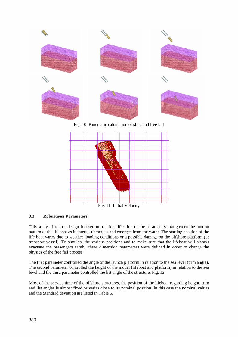
Using the kinematic simulator tool, it was possible to simulate the sliding of the boat on the ramp, -taking friction also into account- and to calculate the free fall of the lifeboat from the tip of the ramp up until a defined distance above the sea level, Fig. 10. At that point the model was stopped by a sensor entity that measures the distance from a specified point and stops the kinematic solver. The velocity components on that position were automatically calculated, converted and were applied on the model as initial conditions ( INTIAL_VELOCITY _GENERATION), Fig. 11.
380
Fig. 10: Kinematic calculation of slide and free fall
Fig. 11: Initial Velocity
3.2 Robustness Parameters This study of robust design focused on the identification of the parameters that govern the motion pattern of the lifeboat as it enters, submerges and emerges from the water. The starting position of the life boat varies due to weather, loading conditions or a possible damage on the offshore platform (or transport vessel). To simulate the various positions and to make sure that the lifeboat will always evacuate the passengers safely, three dimension parameters were defined in order to change the physics of the free fall process. The first parameter controlled the angle of the launch platform in relation to the sea level (trim angle). The second parameter controlled the height of the model (lifeboat and platform) in relation to the sea level and the third parameter controlled the list angle of the structure, Fig. 12. Most of the service time of the offshore structures, the position of the lifeboat regarding height, trim and list angles is almost fixed or varies close to its nominal position. In this case the nominal values and the Standard deviation are listed in Table 5.

381
Fig. 12: Robustness parameters a) Trim angle, b) Drop height, c) List angle
Table 5: Mean values and σ of Robustness input parameters
Parameter Mean value σ Height 36m 1.5 Trim angle 0° (35° launch platform to sea-level) 1.2 List angle 0° 1
These parameters however were not defined by deterministic values but as distribution of values since there is a statistical probability that affects which value appeared (distribution method: Normal). Following the Robust design optimization concept the target was to find an optimum solution for the lifeboat hull that is affected as less as possible from the stochastic parameters variation. 3.3 Shape optimization Parameters Morphing parameters were also introduced that controlled the shape of the lifeboat. Using the special entities of ANSA pre-processor, the Morphing Boxes, one parameter changed the shape of the “nose” of the vessel. Changing the shape of the nose altered the entry behaviour of the lifeboat, Fig. 13. A second morphing parameter was introduced to control the shape of the rear part of the keel of the vessel, Fig. 14. Both morphing parameters were added to examine the relation between the shape of the boat and the accelerations produced during the entry. The shape of both areas, front and rear, significantly affect the negative accelerations produced during the entry of the lifeboat to the water.

382
Fig. 13: Nose shape parameter
Fig. 14: Rear shape parameter These shape parameters were set up in order to minimize these accelerations, making sure the maximum CAR (Combined Acceleration Ratio) index values are below the limits set by the DNV standards.
Fig. 15: Motion pattern and dx distance

383
4. Post processing Using the Optimization tools of the µETA post- processor experiments that resulted in acceptable motion patterns were identified by means of time and distance from the starting position. For each experiment, the distance was measured at the time the COG of the lifeboat surfaced, in order to identify whether the motion pattern was acceptable. Nodal accelerations were also measured at strategically selected history nodes simulating the positions of the passenger seats.
Fig. 16: Local XYZ accelerations vs Time
The results for the acceleration of each history node were calculated for the “moving” local coordinate system of the seats. The maximum values for each ax, ay and az curves were identified and were used in the calculation for the CAR index value using Equation 1. These values were captured as responses and used for constraint and objective entities in the setup of the optimization process. 5. Robust Optimization The modeFRONTIER optimizer has been used in this problem which is able to couple with the ANSA pre-processor. The optimizer gives different values for the three stochastic parameters resulting in a new initial position of the lifeboat. The model’s shape is updated using morphing functionality by updating the discrete values for the two shape parameters. In order to feedback and update the Kinematic solver of this movement, the kinematic entities were also included in the morphing actions. This way, the kinematic solver ran for every different set of Height/Trim/List configuration, resulting in different initial conditions per experiment. A workflow has been created in modeFRONTIER in order to manage the Robust Optimization process. Nodes for ANSA, mETA and a shell node for the LS-DYNA Solver were defined and five input parameters were automatically created in the workflow, Fig. 17. The algorithm selected for this Robust Optimization case was the SIMPLEX. This algorithm provides fast conversion, is able to take into account discrete variables and constraints and does not require a large number of DoE initial experiments. The fact that we had a single objective also supported the selection of the SIMPLEX algorithm that led to a smaller number of total designs.

384
Fig. 17: Optimization Workflow in modeFRONTIER
Distribution and Standard deviation (Multi Objective Robust Design Optimization) properties were assigned to the three input variables that concerned the initial position of the lifeboat. Also the Normal distribution method was selected in order to model the uncertainties of these three input parameters (Trim_rotation, List_Rotation, Height), Fig. 17. Minimum and Maximum possible values were automatically input from ANSA while a value for the Standard deviation was manually added for these three variables.
Fig. 18: Robust design input variable settings
Responses from the postprocessor, regarding motion pattern/distance and the CAR (Combined Acceleration Ration) values for the occupants were defined and assigned as Constraint and Objective respectively. As per DNV standards, at the time the COG of the lifeboat surfaces after the entry face, measuring the distance covered, provides us with an indication whether the motion pattern was acceptable and the minimum distance between lifeboat and host structure is larger than 40 meters. The 99.97% of the distribution of the Distance dx from the source structure was constrained to a minimum value. The 99.97% of the CAR index distribution was also defined as a constraint to be less than 1 and the Objective was the minimization of the 99.97% of the CAR distribution, thus minimizing the accelerations on the human body.

385
Table 6: Robust Optimization Constraints and Objective Constraints 99.97% Distance from source Greater than 40 m 99.97% CAR Less than 1 Objective Minimizew CAR
6. Results The results focused on the accelerations developed during the entry of the lifeboat in the water. The acceleration values were calculated in the form of CAR (Combined Acceleration Ratio) index. The target was to prove the robustness of the design of the freefall configuration while minimizing the CAR index, thus minimizing the accelerations the passengers feel during the entry face. The preliminary results have shown some grouping of the designs in a scatter chart of CAR vs Total Distance from the host structure, Fig. 19. This is consistent with a robust design for the suggested optimization case and the dispersion is within acceptable range.
Fig. 19: CAR index vs Total Distance Scatter chart
Fig. 20: Probability Density Function

386
The standard deviation regarding CAR index is within an acceptable range while the 99.97% of CAR index values was less than 1 that was one of the constraints of the optimization problem, Fig. 20. Also the results show that there was a small gradual minimization of the 99.97% of the CAR index values, which suggests that the robust analysis coupled with the shape optimization of nose and rear shape of the life boat managed to decrease the acceleration values that the passengers undergo when the lifeboat enters the seawater. 7. Future work Due to the complexity and the great amount of parameters that affect the launch of the lifeboat, more work is required in order to have a complete overview of the process. The major external parameters that greatly affect all stages of the process, the wind and waves are going to be investigated and added to the robustness analysis. Stochastic design variables will be created controlling the various wind speed and wave height that are possible in the lifetime of an offshore structure. Furthermore utilizing the occupant safety tools included in ANSA, (dummy and seat positioning, seat belt tool) we will get much more accurate and detailed results regarding the accelerations on the human body and possible impact injuries of the occupant. References DNV (2010), Design of Free Fall Lifeboats, 1st Offshore Standard DNV-OSO-E406 MØRCH, H.J.; ENGER, S.; PERIC, M.; SCHRECK, E. (2008), Simulation of lifeboat launching under storm conditions, 6th Int. Conf. CFD in Oil & Gas, Metallurgical and Process Industries SINTEF/NTNU, Trondheim WANG, J.; CHEN, H. (2007) Fluid structure interaction for immersed bodies, 6th European LS-DYNA User’s Conf., pp.4.3-4.8 TOKURA, S. (2015), Validation of Fluid Analysis Capabilities in LS-DYNA Based on Experimental Result, 10th European LS-DYNA Conf., Würzburg LS-DYNA (2006), Keyword User’s Manual Version 971, Livermore Software Technology Corp., Livermore modeFRONTIER (2014), User Manual modeFRONTIERTM 2014, Esteco SpA 2014