design practice for soil stabilization in subsidence area
TRANSCRIPT

Design Practice For SoilStabilization in Subsidence
AreaBeecroft A. Shittu, P.E.
Supervising EngineerHouston Airport System
Planning/Design/Construction

Bush Intercontinental Airport
The IAH Master Planwill serve as an integral
planning and decision tool insupport of the short,
intermediate, and long-termdevelopment and operation
of IAH as defined in the 2006GBIAH Master Plan
(DMJM & RS&H AviationSept. 2006 Technical Report).
AirportMaster Plan
MasterDrainage
Plan

GBIAH MASTER PLAN

Vertical Datums• North American Vertical Datum of 1988 (NAVD 88)• National Geodetic Vertical Datum of 1929 (NGVD 29)
– 1973 Adjustment• IAH
– NGVD 1929, 1973 Adj.– NAVD 1988, 1991 Adj. (2001 Drainage Master Plan Update)– NAVD 1988, 2001 Adj. (2007 Drainage Master Plan Update)

Converting Elevation DataConverting Elevation Data
•• In 2001 DMPU used a uniform Adjustment from NGVD 1929, 1973In 2001 DMPU used a uniform Adjustment from NGVD 1929, 1973Adjustment to NAVD 1988, 1991 AdjustmentAdjustment to NAVD 1988, 1991 Adjustment
•• Adjust from NAVD 1988, 1991 Adjustment to NAVD 1988, 2001Adjust from NAVD 1988, 1991 Adjustment to NAVD 1988, 2001AdjustmentAdjustment–– National Geodetic SurveyNational Geodetic Survey–– TSARP Flood Plain Reference Mark SystemTSARP Flood Plain Reference Mark System–– IAH Survey Manual UpdateIAH Survey Manual Update

www.NGS.NOAA.GOV

Benchmarks with 1973 ElevationsBenchmarks with 1973 Elevations

Benchmarks with 2001 Elevations

1978-2001 Adjustment Map

GBIAH ADJUSTMENT MAP

PRESENTATION OUTLINE
Objective• Subgrade Characterization• Evaluation of Subgrade Stabilization on
Pavement Performance• Research in progress

TERMINAL & RUNWAY
• $1.6B program– 35 miles of runways, taxiways– 2.2M cu yds of PCC– 29M cu yds of earthwork
• Modern, parallel runway configuration• Massive earthmoving, construction, hydraulic,
environmental impact challenges
SUBGRADE STABILIZATION
Definition
The improvement of pertinent soilengineering properties by the addition ofadditives so that the soil can effectively serveits function in the construction and life of apavement

TECHNICAL OBJECTIVES Some recognized direct causes of
subgrade/subbase non-uniformity include– (1) Expansive soil
– (2) Non-uniform strength and stiffness due tovariable soil type, moisture content and density
– (3) Pumping and rutting
– (4) Cut/fill transitions
– (5) Poor grading.

REASONS TO STABILIZE
• IMPROVE ENGINEERING PROPERTIES OF IN-SITUSOILS (STRENGTH WATERPROOF)
• RECYCLE EXISTING PAVEMENTS/BASES• IMPROVE DURABILITY• REDUCE THICKNESS OF PAVEMENT• FACILITATE CONSTRUCTION

FAA COMPARATIVE ANALYSIS

SUBGRADE and SUBBASECHARACTERIZATION
• FAA thickness design procedure based on subgradeCBR.
• Current FAA thickness design procedure (based onLayered Elastic Analysis) uses CBR or modulus(estimated from CBR)
• E = 1500 * CBR (for CBR 2 to 200)


Subgrade and Subbase Characterization
• E –CBR relationship• Strong trend• Lot of scatter• Generally recognized that• For weak soils, CBR dependent on shear strength;• For strong soils, CBR dependent on bulk modulus

Subgrade and Subbase Characterization
The manner of the scatter in the modulus versus CBRcorrelation indicates that a strong combination of multipleunderlying characteristics determines the CBR ofmaterials at any given CBR value.
• From new FAA thickness design procedures, thecapability for measuring resilient modulus of soils willbecome more common.
• Resilient modulus, in combination with a measure ofstrength such as shear strength, could well displaceCBR as a means of characterizing subgrade soils.

Subgrade and Subbase Characterization
• Emphasis is placed on subgrade/subbase stiffness (i.e.,modulus of subgrade reaction, ks) for designing PCCpavement thickness
• Performance monitoring suggests that uniformity ofstiffness is the key for ensuring long-term performance.
• The subgrade/subbase should be uniform, with noabrupt changes in “degree of support” .
• Stabilization has a significant influence on the “stressintensity” and “deflection” of the pavement support.

Subgrade and Subbase Characterization
• Laboratory Testing –• Atterberg Limit (LL, PL, PI of soils)• Grain size analysis (hydrometer tests and sieve
analysis)• Modified Proctor Tests (moisture-density
relationship)• Unconfined compressive strength tests (shear
strength of cohesive soils)• Triaxial shear tests (shear strength parameters
for cohesionless soils)• Dynamic Triaxial Tests (resilient modulus and
permanent deformation behavior)

DESIGN FOR DIFFERENTIAL SETTLEMENT
RUNWAY 8L - 26R

RUNWAY 8L -26R
_________________________
17” Concrete Pavement
___________________________________________
2” Asphalt Bond Breaker
A____________________________________________________________________________ _____A
13” Econcrete
___________________________________________
8” Cement Flyash Sub -grade
___________________________________________
Compacted Embankment
___________________________________________
Subgrade
At Layer A -A (Elevation) Normal Stress = 20.70 psi; Normal Strain = 0.0000067
Shear Stress = 8.2 psi; Shear Strain = 0.0000049
Principal Stress = 22 psi; Principal Strain = 0.0000072
Displacement (Deflection) = 0.05 ”

DESIGN FOR DIFFERENTIAL SETTLEMENT
• To design for differential settlement in the areas where consolidationof the backfilled soil were yet to take place
• Dr. Dallas Little of Texas Transportation Institute• Did some finite element analysis.• This was done by modeling an abrupt (transition between the various
pits undergoing settlement. The finite element analysis showed thatthe effect of the settlement discontinuity is significant.
• It was decided to use a Stress Absorbing Membrane Interlayer (SAMI)to absorb some of the energy due to the differential settlements. SAMIwas added to the asphalt bond breaker in these areas.
• In addition two layers of reinforcing steel in the concrete pavement.This extra layer of steel at the bottom of the concrete pavement wouldhelp mitigate and arrest the cracks due to excessive tensile stressesin the event of differential settlement.

Reasons to Stabilize
Improve DurabilityReduce Thickness of PavementFacilitate Construction

SUBGRADE PROPERTIES Soil Type• – Heavy Clay• – Lean clay• – Silt• Soil Condition• – Wet• – Optimum• – Dry• Stabilization Agents• – Cement• – Lime• – Lime/Fly Ash• – Cement/Fly Ash

Stabilizer Selection
• Soil stabilization index system• Developed by jon epps for the corps of engineers


Flyash
• Most commonly used w/lime on silts• Pozzolanic• High quantities normally required

General Use• lime - high pi soils (usually >10)• Portland cement -pi 10-30• Asphalt -pi < 10 (sands)• Flyash – fine grained silts

Lime
Percent by weight - 2% for modification - 3-6% for stabilization

Cement
Percent by weight - 3-7% for coarse grained material - 6-15% for fine grained material

Cement Requirements

Percent Cement

Cement Curing Time

Water Absorption

Asphalt Requirements

Mix Designs
Perform Detailed Mix Design
Consider
- Workability- Strength- Durability- Volume Sensitivity
• Swelling, Shrinkage

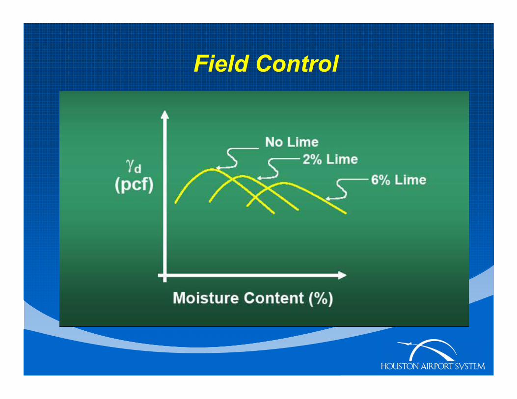
Field Control
• In – Place Density Usually Employed forQC.QA Purpose
• Density/ Moisture Relationship ofStabilized MaterialsChanges with Curing Time andStabilizer Content
Field Control

Field Control

Asphalt
Percent by weight - 2-4% for coarse grained material - 4-6% for fine grained material

SOUTH COMPLEX—RUNWAY 9-27 AND ASSOCIATED TAXIWAYS• 1
987 1,200 psi 8,280KPa• 1993 2,200 psi 15,180KPa• 1997 3,000 psi 20,700KPa• 2001 3,200 psi 22,080KPa• Long-term strength gain• Autogenous healing ofmicrocracks
BIAH South Complex LCF Base Course
05 0 0
1 0 0 01 5 0 02 0 0 02 5 0 03 0 0 03 5 0 04 0 0 0
Time
c o m p r e s s i v es t r e n g t h s
L i n e a r( c o m p r e s s i v es t r e ng t h s )

Research in progress

LCF TECHNOLOGYLCF Technology developed by Nai Yang
Pozzolanic base stabilization4 Airports used LCF base stabilization
Newark International Airport 1969Portland International Airport 1974 Zurich,
Switzerland, International Airport 1979Bush Intercontinental Airport 1986
Adil Godiwalla

Stabilization Methods forProblematic Silt Soils


REFERENCES LOUISIANA TRANSPORTATION RESEARCH CENTER FEDERAL AVIATION ADMINISTRATION
HOUSTON AIRPORT SYSTEM (MASTER PLAN)AMERICAN CONCRETE PAVEMENT ASSOCIATION

Thank You.Questions and Comments