design principles for smoke ventilation in enclosed … · installation of a viable smoke...
TRANSCRIPT
Building Research Establishment Report
Design principles for smoke ventilationin enclosed shopping centres
H P Morgan, BSc, CPhys, MInstP, AIFireE, MSFSE and J P Gardner*, BSc
*Colt International Ltd
Fire Research StationBuilding Research EstablishmentGarston, WatfordWD2 7JR
Prices for all available BRE publications can be obtained from: Construction Research Communications Ltd151 Rosebery AvenueLondon, EC1R 4QX Telephone0171 505 6622Facsimile 0171 505 6606E-mail [email protected]
BR 186 ISBN 0 85125 462 4
© Crown copyright 1990 First published 1990Reprinted with corrections 1991 Second reprint 1991Republished on CD-ROM 1997with permission of the Controllerof HMSO and the Building ResearchEstablishment, by Construction Research Communications Ltd
Anyone wishing to use the information given in this publication should satisfy themselves that it is not out of date, for example with reference to the Building Regulations
Applications to copy all or any part of this publication should be made to: Construction Research Communications Ltd, PO Box 202, Watford, Herts, WD2 7QG

Contents
Page
Foreword v
Introduction 1
Chapter 1 General principles 3
Chapter 2 Design procedure for the mall smoke control system 6
Smoke reservoirs 6
Design fire size 6
Single-storey malls 7
Two-storey malls with small voids 8
Two-storey malls with large voids 10
Multi-storey malls 14
Calculating smoke temperature 15
Mall sprinklers 17
Flowing layer depth 18
Local deepening 18
Inlet air 19
Minimum number of extract points 20
Natural ventilation - area required per reservoir 21
Powered ventilation 22
Chapter 3 Large shop opening onto a mall 23
Chapter 4 Some practical design considerations 25
Factors influencing the design fire 25
The effect of wind on the efficiency of a smoke ventilation system 25
False ceilings in the mall 25
The use of a plenum chamber above a false ceiling in a shop 26
Stores with internal voids 27
Sloping malls 27
Assessment of effective layer depth 27
Smoke flow in low narrow malls 27
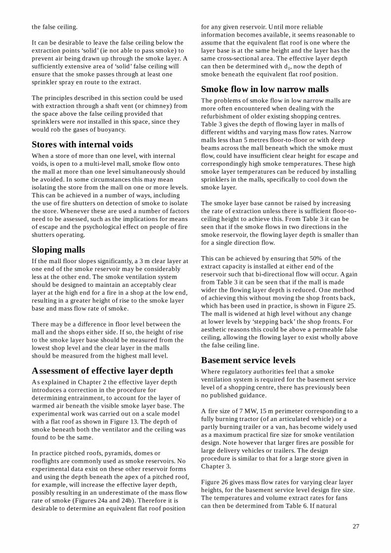
Basement service levels 27
Enclosed car parks 29
Smoke transfer ducts 29
Entrances within the smoke layer 30
Other situations 30
Chapter 5 Some operational factors 31
References 32
iii

Foreword
This Report has been prepared by the Fire Research Station of the Building ResearchEstablishment (BRE) and results from the latest scientific knowledge and practical experience insmoke movement and control. It is an update of Smoke control methods in enclosed shoppingcomplexes of one or more storeys: a design summary published in 1979, and is based uponpreliminary work carried out for BRE by Colt International Limited.
The Report takes into account the comments of a Liaison Committee consisting of industrial andgovernment representatives. The Fire Research Station is also grateful to the Society of Fire SafetyEngineers, the Institute of Fire Engineers and the UK Chapter of the Society of Fire ProtectionEngineers for providing detailed comments which have as far as possible been included.
The Fire Research Station acknowledges the assistance given by Colt International Limited in thepreparation of the final Report.
v
This Report is intended to assist designers of smokeventilation systems in enclosed shopping complexes.Most of the methods advocated are the outcome ofresearch into smoke control by smoke ventilation atthe Fire Research Station, but also take into accountthe recommendations1 of the Working Party on fireprecautions in town centre redevelopment, as well asexperience gained and ideas developed whilst theauthors and their colleagues have discussed manyproposed schemes with interested parties. The primarypurpose of this Report is to summarise the designadvice available from the Fire Research Station at thetime of its preparation, in a readily usable form. Assuch, the Report is neither a detailed engineeringmanual nor is it a scientific review article. Perhapsmost important of all, it is not a summary of thetotality of approaches possible. New methods such asthose based upon computational fluid dynamics, willbe developed as time passes and there will always bespecial cases where existing alternative methods can beadopted.
At peak times a shopping centre can be occupied bythousands of people, and some larger centres by morethan a hundred thousand. A typical centre maycomprise many individual shop units opening onto acommon mall. Although the individual units may beseparated from each other by a dividing wall of fire-resisting construction, usually the shop is either openfronted or only separated from the mall by a glass shopfront. This means that the public areas of the entirecentre can be effectively undivided.
Means of escape from within each shop unit will, ingeneral, be specified (eg BS 5588 Part 22) in the sameway as for shops which are not part of an enclosedcomplex. This means that escape from within the shopsis specified as if the mall were as much a place of safetyas the usual open-sky street. Unfortunately, the mall isa street with a roof, and so cannot be regarded as beingas inherently safe as an open-topped street. Peopleescaping from a shop into a mall will still need to travelalong the mall before exiting to a true place of safety. Itfollows that the mall constitutes an additional stage tothe escape route, which needs to be protected from theeffects of fire and smoke. Ideally, it should approachthe same level of safety as a street for as long as peopleneed to escape through it — even if smoke enters themall from the shop on fire. Details of means of escapeprovisions for the malls can be found elsewhere1.
A shopping complex is a public building and theoccupants will be a cross section of the communityincluding the elderly, children and the disabled. Theywill not necessarily be familiar with the building, orperhaps more importantly, with all the escape routesthat might be provided for them. In many types ofbuilding it is widely recognised that people will
Introduction
commonly try to escape by the same route they had used to enter the premises (see for example, Canter3).It follows that escape via the malls must be assumed,even where other exits are provided1. In this situation along evacuation period can be expected. A detectionand alarm system is required to give early warning of afire, and sprinklers are needed to control its spread.Statistics of fire deaths show that the majority offatalities are due to the effects of smoke.
The ideal option would be to prevent any smoke froma shop fire entering the mall at all. In the majority ofcases, it would either be very difficult or extremelyexpensive to fit a separate smoke extraction system toeach and every shop, however small1. Note that largeshops are, however, an exception to this rule and theprovision of smoke ventilation systems for such shopsis discussed in Chapter 3. Occasionally circumstancesdictate that smoke ventilation fitted to each shop unit,even small units, is the most viable option forprotecting part or all of a mall. (This can apply, forexample, when an old complex is being redeveloped,but the mall is too low and/or too narrow to allow theinstallation of a viable smoke ventilation system in themall itself). There have been several examples of this.Nevertheless it remains generally true that this optionis rarely found to be appropriate for most malls.
Occasionally, one still hears the suggestion that themall should be pressurised to prevent smoke movingfrom a shop into the mall. This is not usually a viableoption by itself where the opening between shop andmall is large (eg an open-fronted shop, or a shop whoseglazing has fallen away in whole or part). This isbecause the airspeed needed from mall into shop inorder to prevent the movement of smoky gases theother way through the same opening, can vary between1/2 and c. 2 ms-1 depending on fire size, gas temperatureetc. All of this air must be continuously removed fromwithin the shop unit in order to maintain the flow. Thequantities of air-handling plant required will exceedthe size of smoke ventilation systems for most typicalshop-front openings.
Where smoke from a fire in a single shop unit couldspread rapidly via the malls through the entire centre,a smoke ventilation system in the malls is essential toensure that escape is unhindered, by ensuring that anylarge quantities of thermally buoyant smoky gases canbe kept separate from (ie above) people who may stillbe using escape routes through the malls. Therefore,the role of a smoke ventilation system is principallyone of life safety. It should also be remembered,however, that firefighting becomes both difficult anddangerous in a smoke-logged mall. It follows that toassist the fire services, the smoke ventilation systemshould be capable of performing its design function fora period of time longer than that required for the
1
public to escape: so an immediate attack on the firecan be made after the arrival of the fire brigade.
Guidance on design principles for smoke ventilationsystems was summarised in a report by Morgan4
published in 1979. This was based on the knowledgeavailable at that time. Since then a great deal ofrelevant research has been carried out, which for themost part has confirmed the guidance given in theoriginal report, but has in some areas highlighted theneed to modify that guidance. A great deal of practicalexperience has been gained in designing such systems.Also in the intervening years, shopping centresthemselves have become larger and more intricate withmany open levels, interconnecting voids, sloping floorsand atrium features. These can result in a very complexpath of smoke flow from the shop in which the firestarts to the eventual point of extraction.
The purpose of this Report is to update the guidanceavailable in the earlier design summary4 to reflectthese changes, to assist designers of smoke controlsystems in enclosed shopping centres. As was the casewith the previous work, this Report only givesguidance in line with current knowledge and generallyaccepted practice. The guidance is based on results ofresearch where possible, but also on the cumulativeexperience of design features, required for regulatorypurposes, of many individual smoke ventilationproposals. Many of these design features have beenevolved over a number of years by consensus betweenregulatory authorities, developers and fire scientists,
2
rather than by specific research. Such advice has beenincluded in this Report with the intention of giving thefullest picture possible. It is therefore likely that someof this guidance will need to be modified in the future,as the results of continued research become available.
A Code of practice5 for enclosed shopping centres iscurrently being prepared by the British StandardsInstitution (BSI). The aim of this Report is to provideguidance only on design principles for smokeventilation and it is hoped to support the Code ratherthan pre-empt it. The Report cannot cover all theinfinite variations of shopping centre design. Instead itgives general principles for the design of efficientsystems, with simplified design procedures for an idealmodel of a shopping mall and then further guidance onfrequently encountered practical problems. Becausethe design procedures are of necessity simplified, theReport also gives their limitations so that, whennecessary, a more detailed design by specialists can becarried out.
A Code of practice for atrium buildings is also beingprepared by the BSI. An atrium can be defined as anyspace penetrating more than one storey of a buildingwhere the space is fully or partially covered. Most atriawithin shopping centres may be considered as part ofthe shopping mall and treated accordingly. Where atriahave mixed occupancies (eg shops and offices) thenreference should be made to the above document,when available, or specialist advice sought.

Smoke from a fire in a shop rises in a plume to theceiling. As the plume rises, air is entrained into it,increasing the volume of smoke and reducing itstemperature. The smoke spreads out underneath theceiling and forms a layer which deepens as the shopbegins to fill with smoke. As the layer deepens, there isless height for the plume of smoke to rise before itreaches the smoke layer. Less air is being entrained,with the result that the temperature is higher onreaching the smoke layer. As this continues, theincreasing smoke layer temperature at some point willoperate the sprinklers. The fire may shatter the shopfront glazing (if present) unless that glazing is fire-resistant. The smoke will then flow out of the shop intothe mall (Figure 1). The change of direction as thesmoke flows out of the shop front results in increasedmixing with the surrounding air.
There is so much mixing that, except close to the fireitself, the hot smoky gases can be regarded asconsisting entirely of warmed air, when calculatingflow. The quantity of smoke particles (and hence theoptical density and visibility through the smoky gases)produced in a fire, depends strongly on the nature ofthe burning material6.
The quantity of hot gases carrying these particles is,however, mainly dependent on the size and rate ofburning (related to the heat output per second) of thefire. Increasing the visibility through these gasesrequires their dilution with clean air, but improvingvisibility (and reducing toxicity) by dilution alone in amall to safe levels after smoke has entered, is not apractical proposition. One suggested safe level ofvisibility7 (about 8 metres — rather a short distance fora mall) would require the hot smoky gases to bediluted by a mass ratio possibly larger than 300, evenafter the gases leave the shop of origin. It follows thenthat hot smoky gases should always be kept spatiallyseparated from escaping people.
One can state as a general principle that air will mixinto a rising stream of hot smoky gases in large
Chapter 1General principles
quantities, but will not mix appreciably into ahorizontally flowing stream of hot smoky gases exceptunder special (and usually local) conditions.
Smoke flowing from the shop onto the mall will rise tothe mall ceiling (Figures 1 and 2). Air will mix into thesmoke as it rises. If no smoke control measures arepresent, the gases will then flow along the mall as aceiling layer (Figure 2a) at a speed8 typically between1 and 2 m/s.
This is faster than the probable escape speed ofpedestrians in a crowded mall9. When the smokereaches the end of the closed mall it will dip down to a low level and be drawn back towards the fire10
(Figure 2b).
If the end of the mall is open, even light winds blowinginto or across the opening will cause severe localdisturbance and mixing, and once again smoke at lowlevel will be drawn back towards the fire10 (Figure 2c).Hence a single-storey mall could become smokelogged within minutes. An unsprinklered fire in asingle-storey shopping centre in Wolverhampton11, isthought to have caused a 100-metre-long mall tobecome untenable within one minute. Similarly shorttimes can be expected to apply to the upper floors of amulti-storey mall. Since it is not usually practical toprevent smoke entering the mall, except for largershops, a mall smoke control system is necessary tocontrol and remove heat and smoke.
The Fire Research Station has extended the ideasdeveloped during its earlier work on the fire venting offactories12 to apply to malls8 in order to use thebuoyancy inherent in fire gases to keep those gasessafely above the heads of people in the malls (Figure3). There are three essential features of a smokeventilation system, without any one of which it will notfunction effectively:
1 There must be some means of forming a smokereservoir to prevent the lateral spread of smoke,
3
Figure 1 Smoke spread and main entrainment sitesin single and two-storey malls

Figure 2a Creation of a moving smoke layer beneath the ceilingof an unventilated mall, showing movement of the displaced air
Figure 2b Recirculation of smoke in an unventilated and closed mall
Figure 2c Mixing of smoke into the air being drawn into anopen-ended mall, caused by wind
Figure 3 Principles of system needed to contain smoke in awell-defined layer (section along mall)
which would result in excessive loss of buoyancy.This reservoir must be designed to contain thesmoke layer base well above head height. Generallyspeaking, malls with high ceilings or rooflights willallow a deeper smoke reservoir and hence a moreeffective smoke ventilation system than in low,narrow malls.
2 There must be extraction of smoke within thereservoir, to prevent the smoke layer building downbelow the design depth. This can be natural,
4
buoyancy driven ventilation or mechanicalextraction, depending on the circumstances. Therate of the exhaust must equal the rate at which thesmoke enters the reservoir from below.
3 Since the gases being extracted consist almostentirely of air that has mixed with the original firegases, fresh air must enter the mall to take its place.It must enter at a rate equal to the rate of extractionof smoke and at a low enough height not to mixprematurely with the smoke.

In a fire most of the important factors are timedependent: the time for a fire to grow from ignition tothe design fire size, time for the mall to smokelog andtime needed for evacuation. Currently there are noreliable data on fire growth rates in retail premises.Smoke filling times are known to be rapid but are notalways easily quantified. The time needed forevacuation is unknown but it could be considerablylonger than the 2.5 minutes escape time used to sizeexit widths to cope with the peak flow rates during thisevacuation period. There is considerable anecdotalevidence within the UK fire services supporting thisview.
These uncertainties lead to many problems indesigning a time dependent smoke ventilation system.The design principles given in this Report are basedinstead on steady state conditions. A design fire is usedwhich has a low probability of being exceeded, and thesmoke ventilation system is designed to remove themass flow rate of smoke necessary to maintain clearconditions in the mall for escape. Sprinklers in shopsare an essential part of the smoke ventilation design inorder to prevent the fire growing beyond the designfire size.
There are other essential factors that should be bornein mind when designing a smoke control system. Whenthe mall has more than one level, it is also necessary torestrict or channel smoke on the lower level in order torestrict entrainment into the plume rising through theupper level. Once the smoke has entered a ceilingreservoir it will flow towards the extraction points.Since this horizontal flow is driven by the gases’ ownbuoyancy, there will be a minimum depth for anyparticular combination of smoke temperature andmass flow rate. This is discussed in greater detail inChapter 2, but this minimum depth will set a limit tothe design for the smoke reservoir, which cannot beshallower.
The capacity of the extraction system depends mainlyon the height the gases have risen to the layer base,and not at all on the area of the floor or the volume ofthe space. Therefore a simple percentage rule fornatural venting, such as 3% of the floor area, or an airchange rate, such as six air changes per hour forpowered ventilation, are misleading.
5

Chapter 2Design procedures for the mall smoke control system
Figure 4 Smoke reservoir in mall with a ceiling heightgreater than that in shops (section across mall)
The following sections outline a general procedurewhich can be followed when designing the mall smokecontrol system. First plan the positions of the smokereservoirs, calculate the mass flow rate of smokeentering the reservoir, and either the ventilation areaof a natural ventilation system or the extract rate of apowered system to remove the same amount of smoke.These procedures have been developed from ‘idealisedmodels’ of shopping malls studied at the Fire ResearchStation. Commonly encountered variations arediscussed further in Chapter 4.
Smoke reservoirsNo smoke layer has a perfectly defined interface withthe colder, clearer air below; there is always a smallamount of cross mixing. This cross mixing has nosignificant effect on the quantity of smoke in ahorizontal ceiling layer but can cause progressive lossof visibility in the air beneath. This loss of visibilityoccurs more rapidly when:
• a ceiling layer is cool (indeed very cool gases will not persist as a layer)
• the hot smoke and the air beneath have a high relative velocity
• turbulence disturbs the interface
Heat is lost from the smoke layer by radiationdownwards and by radiation and conduction to thesurfaces of the reservoir. To prevent excessive heat lossthe size of an individual smoke reservoir within themall is usually taken to be limited to 1000 m2 (or 1300m2 if mechanical extraction is used as its efficiency isless susceptible to heat loss). This recommendationevolved during the early 1970s and is perhaps bestunderstood by noting that in many ‘industrial’ simpleundivided compartment applications of smokeventilation, it has long been the practice to limitreservoir areas to between 2000 m2 and 3000 m2.
In a mall, smoke from shops of up to 1000 m2 area (ifthe mall is naturally ventilated) or up to 1300 m2 (if themall has extract fans) can enter the mall reservoir,giving a total area affected by smoke similar to thelong-standing practice stated above. The maximumdistance between screens forming the boundary of thereservoir should be 60 m. This distancerecommendation follows earlier considerations1
(confirmed in this form by the Liaison Panel consultedin preparation of the present document), and derivesfrom concern over the distance people should beexpected to walk below a smoke layer while escaping.For complex geometries of smoke reservoirs specialistadvice should be sought.
6
The smoke reservoir can often be formed by thedownstand fascia of the shops, combined with screensat intervals along the mall (Figure 4). The fascias arethen necessary, not to prevent the smoke flowing intothe mall from a fire in the shop, but to prevent smokecontained in the mall reservoir flowing into the shopsadjoining the mall. If there are raised rooflights abovethe malls, these can often be utilised as smokereservoirs.
Although the height through which the smoke mayhave to rise to a ventilator installed at the top of a highrooflight may be greater than for lower malls, providedthat the smoke is allowed to build down to the samelevel, the mass flow rate of smoke entering thereservoir is no greater, but the deeper reservoir ofsmoke will produce a greater buoyancy pressure at theceiling.
The screens which form the smoke reservoir should bearranged so that smoke from a fire in any shop canonly flow into one reservoir.
Even with a smoke reservoir limited to 1000 m2,excessive cooling and/or downward mixing can occurin stagnant regions of the smoke layer. To prevent thisthe extraction outlets, be they natural or mechanical,should be distributed over the reservoir so as toprevent stagnant regions being formed. Potentiallystagnant regions of the smoke reservoir can sometimesbe avoided by using smoke transfer ducts (see Chapter 4).
Design fire sizeBefore any smoke ventilation system can be designedit is essential to determine a suitable size of fire, fordesign purposes. This fire size then forms the basis of asmoke ventilation system design.

Ideally the design fire should show the physical sizeand heat output of the fire increasing with time,allowing the growing threat to occupants to becalculated as time increases. Unfortunately there is noavailable research, at the time of preparing thisReport, which allows assessment of the probabilitydistribution describing the variation of fire growthcurves for retail areas. Clearly, one does not want an‘average’ fire for safety design, since typically half ofall fires would grow faster. It is much simpler to assessthe maximum size a fire can reasonably be expected toreach during the escape period, and to design thesystem to cope with that. Note that even here, thestatistical evidence is not strong (see for exampleMorgan and Chandler13) for shopping malls. Furtherresearch is currently in hand to improve this statisticalbasis.
It follows from the foregoing that there is a stronglysubjective element in assessing what fire size isacceptably infrequent for safety design purposes. A 12 m perimeter (3 m × 3 m) 5 MW sprinklercontrolled fire has become the accepted basis in theUK for a smoke ventilation system in a sprinkleredshopping centre1,4,8.
Some factors affecting the design fire size are discussedin Chapter 4. The design principles outlined in thisReport are based upon a 12 m perimeter 5 MW fire.Should a different design fire be considered forwhatever reasons, the equations, figures etc given inthis Report may no longer apply and advice should besought from experts. Other fire sizes have occasionallybeen specified by designers, for both sprinklered andunsprinklered shops. The problem of unsprinkleredshops has been discussed in more detail by Gardner14,who has shown the importance of considering‘flashover’ in such units and the consequent need toconsider potentially very large fires.
Single-storey mallsThe minimum height of the smoke layer base must be2.5 m from the mall floor to ensure safety, andpreferably at least 3 m in a single-storey mall (Figure 5).
Figure 5 Smoke ventilation in a single-storey mall
It may be necessary to raise the smoke layer baseabove this for practical reasons. This will result in anincreased mass flow rate of smoke due to theadditional entrainment, but as the smoke layer base ishigher, a greater degree of safety will have beenachieved. Shop fascias should extend below this height otherwise the layer base would be low enough to enterunaffected shops. Indeed, fascias serve no other usefulsmoke controlling function, except as part of aseparate smoke extraction system within a shop, or tocontain smoke from a very small fire.
Having established the clear layer height in the mall,the mass flow rate of smoke can then be calculated.Recent work by Hinkley15 has confirmed the rate ofentrainment of air into a plume of smoke rising abovea fire as:
M = 0.19 P Y 3/2 (1)
where M = mass flow rate of smoke entering the smoke layer within the shop (kg/s)
P = the perimeter of the fire (m)Y = the height from the base of the fire to
the smoke layer (m)
There is no information available to show howEquation 1 (or any current alternatives) should bemodified to allow for the effects of sprinkler-sprayinteractions. Consequently it is used here unmodified.
Experiments have shown16 that the smoke flowingfrom the shop onto the mall becomes turbulent withincreasing mixing of air. The mass flow rate of smokeentering the reservoir is approximately double theamount given by Equation 1, where Y is now theheight from the fire to the base of the mall smoke layer(Figure 5). Figure 6 shows the mass flow rate of smokygases entering the layer at different layer heights in asingle-storey mall. This can be calculated from:
M = 0.38 P Y 3/2 (2)
The Fire Research Station is currently studyingentrainment into smoke flow from compartments. Thepurpose of this work is to determine more accuratelythe influence of such factors as compartment openinggeometry, the presence of a downstand fascia andbalcony/downstand combinations. It follows thatEquation 2 may be superseded in due course.
If the clear layer in the mall is much higher than theshopfront opening, then the plume of smoke rising tothe smoke layer will be similar to a two-storeyshopping centre (Figure 7). Where this heightdifference (hr) between the shopfront opening and thesmoke layer base is more than 2 m (Figure 7) the massflow rate should be obtained using the procedure fortwo-storey shopping centres given later in this chapteron page 10.
7

8
Figure 6 Rate of production of hot smoky gases ina single-storey mall from a 5MW fire
Figure 7 Additional entrainment with the smoke basewell above the shop front opening
Two-storey malls with small voidsWhen a fire occurs on the lower level of a two-storeymall, a plume of smoke has further to rise beforeentering the smoke reservoir. This results in greaterentrainment of air, hence a larger quantity of smoke.The smoke layer on the upper level will then be coolerand less well defined. In this case the smoke layershould be not less than 3 m above the upper floor leveland preferably more than 3.5 m. Again, shop fasciasshould extend below this height otherwise the layerbase would be low enough to enter unaffected stores.
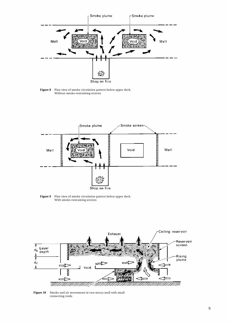
In a shopping centre which has small voids connectinglevels, smoke from a fire in a lower level shop will flowout of the shop and spread in a complicated horizontalcirculation pattern beneath the ceiling (ie beneath theupper deck) (Figure 8). Where smoke reaches the edgeof a void linking the two levels, some will flow over theedge producing an extensive plume above each void,rising through the upper level.
Air mixes into these plumes, resulting in extremelylarge quantities of very cool gas collecting in the upperlevel ceiling reservoir. This in turn reduces theefficiency of buoyancy-driven venting as well asincreasing downward mixing from the ceiling layer. Tominimise this mixing of air into the plume, smokescreens of at least 1.5 m depth17 (actuated by smokedetectors or as permanent features) should be hungbelow the lower level ceiling (ie below the upper deck)in order to restrict the lateral spread of smoke andensure that all the smoke from a fire passes throughonly one void (Figures 9 and 10). The approachoutlined in this section will only apply when the void issmall enough in relation to the mall, and the screensare arranged so that smoke can flow freely into thevoid around its perimeter in a ‘swirling’ pattern (Figure 9).
The perimeter of the rising plume, which stronglyaffects the rate of the mixing of air into the plume,then depends only on the size of the void. Experimentswith scale models17 suggest that the largest voidconsistent with this type of smoke control systemwould have a perimeter of between 35 and 45m.
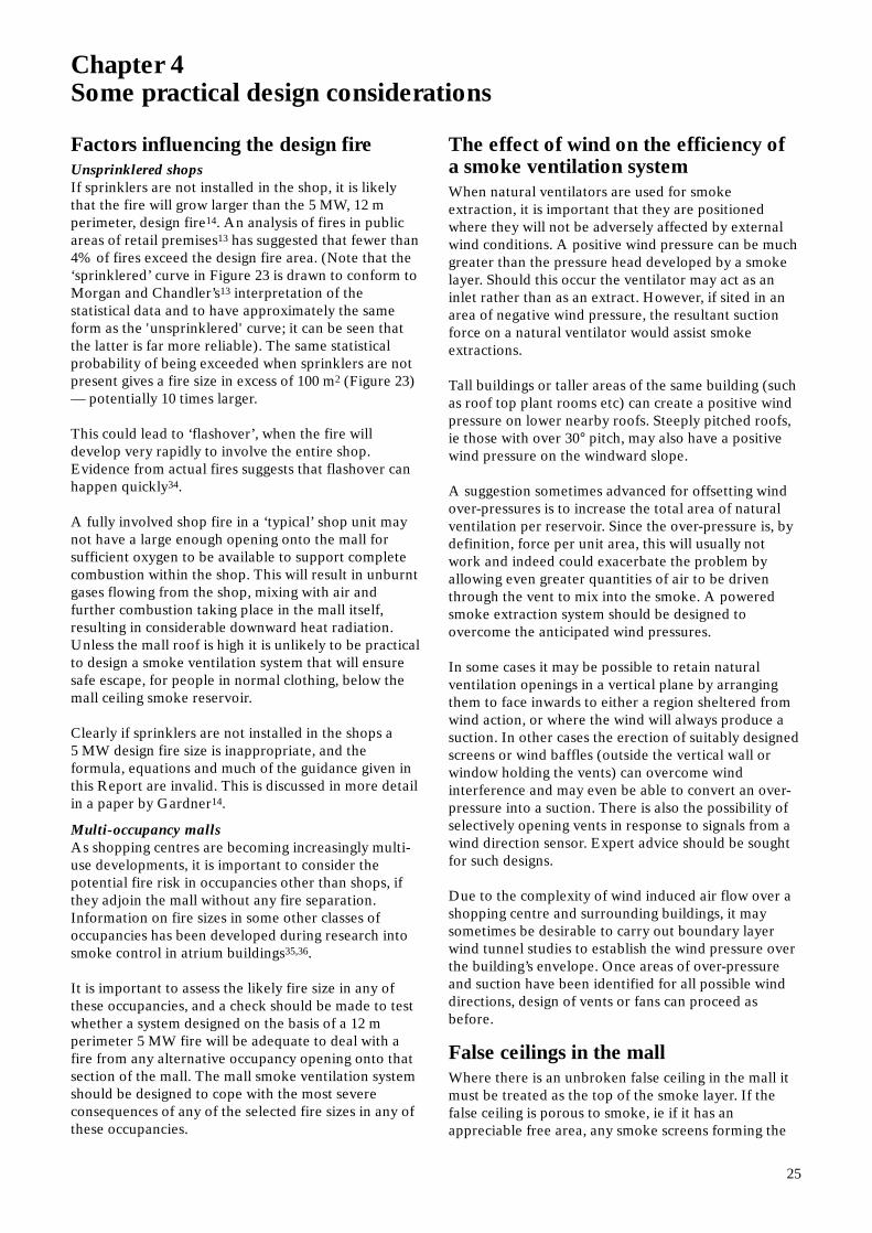
There are no adequate theories to relate the quantitiesof smoke entering the reservoirs, to the height fromthe upper floor to the smoke base. Figure 11 shows thevalues of the mass flow rate (M) entering the reservoirfor different heights of ceiling reservoir smoke baseabove the upper floor, and for three different sizes ofvoid (indicated by their respective perimeters), basedon the voids used in the scale-model experiments.Other void perimeters must be inferred byinterpolation.
Figure 11 applies to a 5 MW fire occurring in a shop onthe lower levels, and is derived from experiments on aone-tenth scale model17 representing a mall of 5 mfloor-to-floor height. Note that extrapolating too far
9
Figure 8 Plan view of smoke circulation pattern below upper deck.Without smoke-restraining screens
Figure 9 Plan view of smoke circulation pattern below upper deck.With smoke-restraining screens
Figure 10 Smoke and air movements in two-storey mall with smallconnecting voids
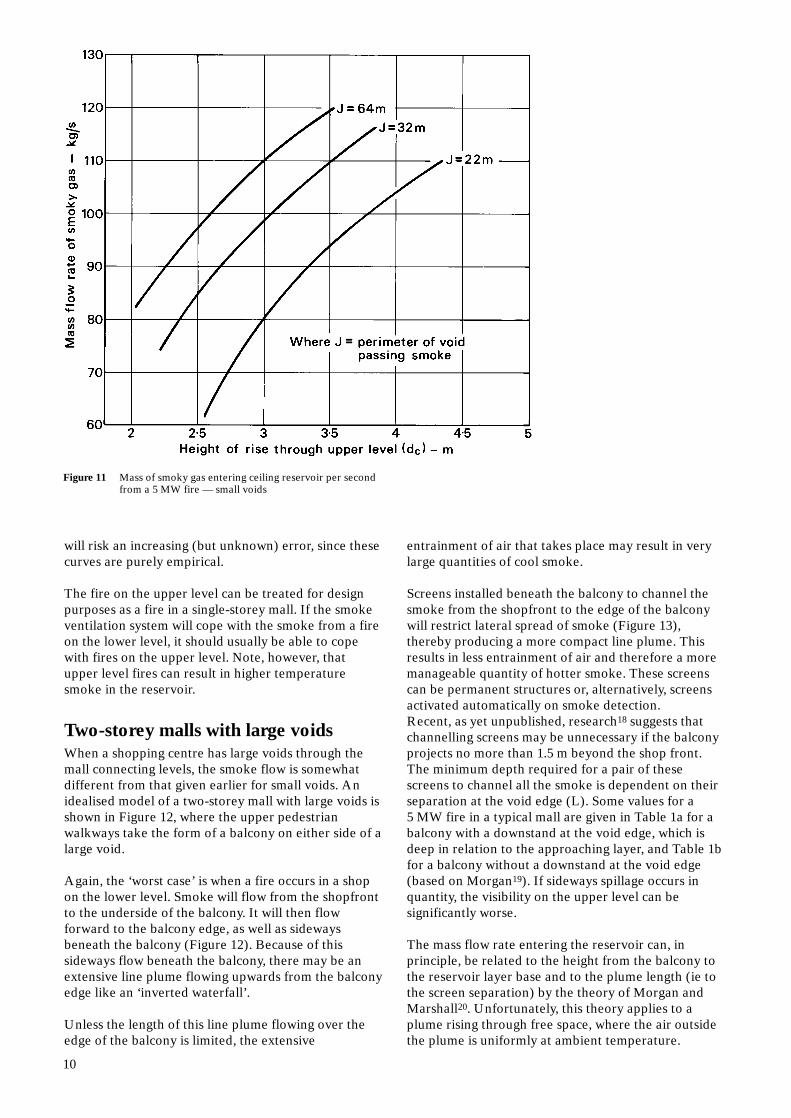
Figure 11 Mass of smoky gas entering ceiling reservoir per secondfrom a 5 MW fire — small voids
will risk an increasing (but unknown) error, since thesecurves are purely empirical.
The fire on the upper level can be treated for designpurposes as a fire in a single-storey mall. If the smokeventilation system will cope with the smoke from a fireon the lower level, it should usually be able to copewith fires on the upper level. Note, however, thatupper level fires can result in higher temperaturesmoke in the reservoir.
Two-storey malls with large voidsWhen a shopping centre has large voids through themall connecting levels, the smoke flow is somewhatdifferent from that given earlier for small voids. Anidealised model of a two-storey mall with large voids isshown in Figure 12, where the upper pedestrianwalkways take the form of a balcony on either side of alarge void.
Again, the ‘worst case’ is when a fire occurs in a shopon the lower level. Smoke will flow from the shopfrontto the underside of the balcony. It will then flowforward to the balcony edge, as well as sidewaysbeneath the balcony (Figure 12). Because of thissideways flow beneath the balcony, there may be anextensive line plume flowing upwards from the balconyedge like an ‘inverted waterfall’.
Unless the length of this line plume flowing over theedge of the balcony is limited, the extensive
10
entrainment of air that takes place may result in verylarge quantities of cool smoke.
Screens installed beneath the balcony to channel thesmoke from the shopfront to the edge of the balconywill restrict lateral spread of smoke (Figure 13),thereby producing a more compact line plume. Thisresults in less entrainment of air and therefore a moremanageable quantity of hotter smoke. These screenscan be permanent structures or, alternatively, screensactivated automatically on smoke detection.Recent, as yet unpublished, research18 suggests thatchannelling screens may be unnecessary if the balconyprojects no more than 1.5 m beyond the shop front.The minimum depth required for a pair of thesescreens to channel all the smoke is dependent on theirseparation at the void edge (L). Some values for a5 MW fire in a typical mall are given in Table 1a for abalcony with a downstand at the void edge, which isdeep in relation to the approaching layer, and Table 1bfor a balcony without a downstand at the void edge(based on Morgan19). If sideways spillage occurs inquantity, the visibility on the upper level can besignificantly worse.
The mass flow rate entering the reservoir can, inprinciple, be related to the height from the balcony tothe reservoir layer base and to the plume length (ie tothe screen separation) by the theory of Morgan andMarshall20. Unfortunately, this theory applies to aplume rising through free space, where the air outsidethe plume is uniformly at ambient temperature.

11
Figure 12 Smoke spread beneath a balcony producinga long line plume
The smoke layer in a mall ceiling reservoir does nothave a well defined base (especially in a two-storeymall where there might be a deep layer of cool smoke).Even below the nominal layer base (ie d1 below theceiling, Figure 13, which corresponds closely to thevisible layer base17), there is a temperature excessrelative to the temperature of the incoming air whichincreases with height (Figure 14).
To apply the theory20 to a calculation of the mass flowrates of smoke entering the reservoir, one mustintroduce a correction factor for the smoke layer depthin a reservoir. Experiments with flat roofed models21
have shown that for calculating plume entrainment, theeffective layer depth (d2) is 1.26 times the nominal andvisible layer depth (d1) which has been chosen forreasons of visibility and safety. In practice manyshopping malls have roofs which are not flat, and it isnecessary to assess the result of this on the effectivelayer depth. This is examined more closely in Chapter 4.
Results from such calculations for a number of valuesof channelling screen separation, are shown graphicallyin Figure 15. These results include an allowance forentrainment of air into the ends of the plume. Thiscorrection method follows that of Morgan andMarshall21, which supersedes their earlier approach20.
Once the height of the nominal layer base (h-d1) hasbeen chosen on safety grounds, and the channellingscreens separation L (and hence also channellingscreen depth using Tables 1a or 1b) has been chosen onpracticability grounds, (eg such that the screens contactthe walls separating the shop) then Figure 15 can beused to find the mass flow rate of smoke entering thereservoir.
It should be noted that once the height of the layerbase (h-d1) has been selected, d1 can be used instead ofd2 for greater simplicity in interpreting Figure 15 andin designing the consequent smoke extraction. Thisresults in an ‘overdesign’ of the extract capacity, which

Figure 13 The use of smoke-channelling screens to produce acompact rising plume
thus errs on the side of safety. In experiments values of(h-d2) as low as a full-scale equivalent 0.75 m wereobtained. For a very deep layer, one sometimes findsthat (h-d2) can sometimes be negative. Thiscorresponds to a plume moving downwards which isimpossible in this context and shows that the methodbreaks down under these conditions. It follows thatwherever (h-d2) is less than 0.75 m, it would be safe touse (h-d1) instead for estimating entrainment.
The results given in Figure 15 are representative oftypical shop/balcony geometries. In practice theshopfront geometry, presence or absence of a deepdownstand fascia and a balcony will affect the massflow rate of smoke. For example, many malls will havethe upper walkway set back above the shop units onthe storey below with no balcony projecting beyondthe lower shop front. In such designs the shop wallsthemselves act as channelling screens. Where such ashop has a downstand fascia, the plume’s rise (h-d2)
12
should be measured from the bottom of thedownstand. Figure 15 can again be used to estimate theentrainment into the plume, but a more precisecalculation for this case is feasible22.
Similarly, results given in Figure 15 are for a line plumerising through an upper level where air is entrained onboth sides. If the plume is rising against a verticalsurface (such as a wall or shopfront on the levelabove), then air will only be entrained into one side.Recent research work22,23 has enabled a more detailedanalysis of the fire compartment conditions andsubsequent plume entrainment to be carried out takinginto account these factors. This fire engineeringapproach is of necessity more complicated and needsindividual consideration.
An alternative method of calculating the entrainmentinto the line plume is due to Thomas24. This treats theplume in a 'far plume' approximation apparently rising

Table 1a Minimum depth of channelling screens— downstand at void edge
Note: The minimum depth is that below the lowest transverse obstacle
Screen separation Minimum screenat edge L depth
(m) (m)
4 2.76 2.48 2.2
10 2.114 1.8
Table 1 b Minimum depth of channelling screens— no downstand at void edge
Note: The minimum depth is that below thelowest transverse obstacle
Screen separation Minimum screenat edge L depth
(m) (m)
4 1.66 1.48 1.3
10 1.214 1.1
from a line source of zero thickness some distancebelow the void edge. The relevant formula is:
where M = mass flow of smoky gases passing height z (kg s-1)
ρ = density of warm gases at height z (kg m-3)Q = heat flux in gases (kW)L = length of void edge past which gases spill
(m)Cp = specific heat of air (kJ kg-1 K-1) T1 = absolute ambient temperature (K)∆ = empirical height of virtual source below
void edge (m)z = height above void edge (m)
gQL2 1/3(z + ∆) (3)M = 0.58ρ
ρCpT1
0.22 (z + 2∆) 2/3
× 1 + L
Morgan’s re-analysis25 of Law’s earlier paper26,concluding that the effective depth d2 of the reservoirlayer should be used when the plume rises within aclosed space such as a mall, should apply equally toThomas’s work. This means that z should be taken tobe (h-d2), as earlier in this section. Again fromMorgan25, one can take ∆ = 0.3 times the height of thecompartment (ie shop unit) opening, althoughcomparisons between Equation 3 and the modifiedform22 of Morgan and Marshall’s method20 suggest thatthe value of ∆ may be sensitive to the parameters ofthe horizontal flow approaching the void. In thiscontext it is noteworthy that Law26 derived a value of∆ = 0.67 times the height of the compartment based ondifferent experimental data.
It should be realised that the derivation of Equation 3limits its application to scenarios where smoky gasesissue directly from the compartment on fire, with abalcony projecting beyond. For two-storey mallsEquation 3 and Figure 15 should give broadly similar
13

Figure 14 A typical temperature profile for a reservoir layer
results, but under some circumstances significantdiscrepancies can occur because of the apparentvariability of ∆. Nevertheless, Equation 3 can be a veryuseful way of estimating entrainment for geometriesdeparting significantly from Figure 15.
Multi-storey mallsFrom the previous section it can be seen that when afire occurs in a ground floor shop and rises through anupper level, a very large quantity of smoke isproduced. If this is extended to a three-storey mall theresult is an impracticably large quantity of very coolsmoke. Therefore it is not usually possible to design apractical smoke ventilation system which allows smokefrom more than the top two levels of a multi-storeymall to rise up through the mall and maintain a clearlayer for escape on the upper level. The limiting factorhere is not the height to the top of the smoke reservoir,but the height of rise to the smoke layer base.
A multi-storey mall can instead be treated as a stack ofsingle-storey malls, with each level having a separatesmoke ventilation system. Clearly this technique canalso be used in a two-storey mall if so desired. Figures16 to 18 illustrate in schematic form a mall whoseupper floor (two levels only are shown in the figures) ispenetrated by voids which leave a considerable areafor pedestrians. On the lower level there is a large areasituated below this upper deck. If screens (activated bysmoke detectors or as permanent features) are hung
14
down from the void edges, the region below the upperdeck can be turned into a ceiling reservoir similar tothat of a single-storey mall, albeit a more complicatedgeometry.
This reservoir can then be provided with its ownsmoke extraction system. Other screens can bepositioned across the mall to limit the size of thisreservoir, as for a single-storey mall.
The screens around the voids will, in general, be fairlyclose to potential fire compartments (ie shops). Beingclose, smoke issuing from such a compartment willdeepen locally on meeting a transverse barrier. Thedepth of these screens should take into account localdeepening27 — see page 18. Smoke removed fromthese lower level reservoirs should usually be ducted tooutside the building but can be ducted into the ceilingreservoir of the top floor ( Figure 18). The mass flowrate of smoke exhaust for the top floor can becalculated as if it were a single-storey mall.
There will often be some small smoke spillages underthe void screens, which will contribute to a ‘fogging’ ofthe upper levels. This can be controlled by permittingsome ventilation of these upper levels to operate, toflush out this stray smoke. To minimise such spillagesand limit the amount of smoke below the ceiling layeron the affected level, it is desirable to simplify thegeometry of the ceiling reservoir where possible.The

Figure 15 Mass of smoke entering ceiling reservoir per second from a 5MW fire — large voids
void screens tend to split the smoke flow into separatestreams within the reservoir (Figure 16).
These streams can meet further along the reservoir, asshown. Such opposed smoke flows produce turbulenceand downward mixing of smoke into the air below. Itfollows that it is an advantage to keep a simplereservoir geometry. It is also important to provide thefull ‘flushing’ clean air inflow below the ceilingreservoir at the affected level.
A lesser amount of ‘flushing air flow’ is desirable onthe top level when lower reservoirs are vented to acommon top level reservoir (Figure 18). This can easilybe provided by increasing the smoke extraction fromthe top reservoir by 10% above that needed to removeall the smoke arriving from below.
Calculating smoke temperatureThe temperature rise of the smoke layer, aboveambient, is given in Table 2, for a 5 MW fire (ignoringany further cooling) and can be calculated from:
where Q = heat flow rate (kW)θ = temperature rise of the smoke layer
above ambient (°C)Cp = specific heat capacity of the gases
(kJ/kgK)M = mass flow rate of smoky gases (kg/s)
High smoke layer temperature will result in intenseheat radiation causing difficulties for people escaping
θ = Q (4)MCp
15

16
Figure 16 Schematic plan of multi-storey mall with a smoke reservoir on each level
Figure 17 Schematic section of a two-storey mall with a smoke reservoir on the lower level
Figure 18 Schematic section of a two-storey mall with lower smoke reservoir venting into the upper reservoir

Table 2 Volume flow rate and temperature of gases from a 5 MW fire(ignoring cooling)
Mass flow rate Temperature of gases Volume rate of extraction(Mass rate of extraction) above ambient (at maximum temperature)
kg/s °C m3/s
9 556 21.512 417 2415 333 2618 278 2924 208 3430 167 3936 139 4350 100 5565 77 6780 63 7995 53 91.5
110 45 103.5 130 38 120150 33 136
beneath the smoke layer in the mall. To reduce theintensity of heat radiation the smoke layertemperature in the malls should be less than 200°C. Ingeneral a higher clear layer beneath the smoke layerwill lead to more air being entrained into the risingsmoke plume and therefore lower smoketemperatures. If the height of the mall is restricted,then it may not be practical to increase the clear layerheight in order to reduce the smoke layer temperature,in which case consideration may be given to installingsprinklers into the malls specifically to reduce the smoke layer temperature by sprinkler cooling. This isdiscussed further in the following section.
Mall sprinklersSprinklers in shops are an essential part of the smokeventilation design in order to prevent a fire growingbeyond the design fire size. Sprinkler operation in themalls will lead to increased heat loss reducing thebuoyancy of smoke, which in turn can contribute to aprogressive loss of visibility under the smoky layer.However, gases sufficiently hot enough to set offsprinklers will remain initially as a thermally buoyantlayer under the ceiling.
When the fire occurs in a shop, operation of sprinklersin the mall will not assist in controlling it. If too manysprinklers operated in the malls sprinklers in the shopscould become less effective as the available watersupply approaches its limits.
Malls should be sprinklered if they contain sufficientcombustibles to support a fire larger than the designfire size of 5 MW, 12 m perimeter, during theiroperational lifetime. Note however that sprinklersinstalled at high level in a multi-storey mall areunlikely to operate unless the fire size reached is muchlarger than this.
Sprinkler cooling can be used in the malls to reducethe smoke layer temperature to below 200°C, abovewhich heat radiation from the layer is likely to impedeescape beneath.
A natural ventilation system relies on the buoyancy ofthe smoke for extraction, therefore if sprinkler coolingis underestimated, the use of unrealistically high smoketemperatures could lead to the system beingunderdesigned. Conversely a powered extract system,to a reasonable approximation, removes a fixedvolume of smoke irrespective of temperature.Therefore if the extent of sprinkler cooling isoverestimated the system could be underdesigned. Theheat lost from smoky gases to sprinklers in the mall iscurrently the subject of research although data suitablefor design application is not yet available.
An approximate calculation approach can be used, asfollows:
If the smoke passing a sprinkler is hotter than thesprinkler operating temperature that sprinkler willeventually be set off. The sprinkler spray will then coolthe smoke. If the smoke is still hot enough, the nextsprinkler will operate, cooling the smoke further. Astage will be reached when the smoke temperature isinsufficient to set off further sprinklers. The smokelayer temperature can thereafter simply be assumed tobe approximately equal to the sprinkler operatingtemperature if natural vents are used.
The cooling effect of sprinklers in the malls can beignored in determining the volume extract raterequired for fans. This will err on the side of safety.Alternatively this cooling and the consequentcontraction of the smoky gases can be approximatelyestimated on the basis of an average value between thesprinkler operating temperature and the calculated
17
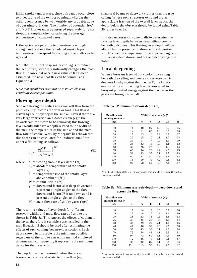
Table 3b Minimum reservoir depth — deep downstandacross the flow
* For bi-directional flow of smoky gases this should be twice the actual reservoir width
Mass flow rate Width of reservoir (m)*entering reservoir
(kg/s) 4 6 8 10 12 15
10 1.8 1.4 1.2 1.0 0.9 0.815 2.3 1.8 1.5 1.3 1.1 1.020 2.8 2.2 1.8 1.5 1.4 1.225 3.3 2.5 2.1 1.8 1.6 1.430 3.8 2.9 2.4 2.1 1.8 1.640 4.7 3.6 3.0 2.6 2.3 2.050 5.7 4.3 3.6 3.1 2.7 2.470 7.5 5.8 4.8 4.1 3.6 3.190 9.4 7.2 6.0 5.1 4.5 3.9
110 11.2 8.6 7.1 6.1 5.4 4.7130 13.1 10.0 8.2 7.1 6.3 5.4150 15 11.5 9.5 8.2 7.2 6.2
Table 3a Minimum reservoir depth (m)
* For bi-directional flow of smoky gases this should be twice the actual reservoir width
Mass flow rate Width of reservoir (m)*entering reservoir
(kg/s) 4 6 8 10 12 15
10 1.1 0.8 0.7 0.6 0.5 0.515 1.4 1.1 0.9 0.8 0.7 0.620 1.7 1.3 1.1 0.9 0.8 0.725 2.0 1.5 1.2 1.1 1.0 0.830 2.3 1.7 1.4 1.2 1.1 0.940 2.8 2.2 1.8 1.5 1.4 1.250 3.4 2.6 2.1 1.8 1.6 1.470 4.5 3.4 2.8 2.4 2.2 1.990 5.6 4.3 3.5 3.1 2.7 2.3
110 6.7 5.1 4.2 3.6 3.3 2.8130 7.8 6.0 4.9 4.2 3.8 3.2150 9.0 6.8 5.6 4.9 4.3 3.7
initial smoke temperature, since a fire may occur closeto at least one of the extract openings, whereas theother openings may be well outside any probable zoneof operating sprinklers. The number of potential ‘hot’and ‘cool’ intakes must be assessed separately for eachshopping complex when calculating the averagetemperature of extracted gases.
If the sprinkler operating temperature is set highenough and is above the calculated smoke layertemperature, then sprinkler cooling in the malls can beignored.
Note that the effect of sprinkler cooling is to reducethe heat flux Q without significantly changing the massflux. It follows that once a new value of θ has beenestimated, the new heat flux can be found usingEquation 4.
Note that sprinklers must not be installed close toventilator extract positions.
Flowing layer depthSmoke entering the ceiling reservoir will flow from thepoint of entry towards the vent or fans. This flow isdriven by the buoyancy of the smoke. Even if there is avery large ventilation area downstream (eg if thedownstream roof were to be removed) this flowinglayer would still have a depth related to the width ofthe mall, the temperature of the smoke and the massflow rate of smoke. Work by Morgan19 has shown thatthis depth can be calculated for unidirectional flowunder a flat ceiling, as follows:
where d1 = flowing smoke layer depth (m)Tc = absolute temperature of the smoke
layer (K)θ = temperature rise of the smoke layer
above ambient (°C)W = channel width (m)γ = downstand factor 36 if deep downstand
is present at right angles to the flow;downstand factor 78 if no downstand is present at right angles to the flow
M = mass flow rate of smoky gases (kg/s)
The resulting values of layer depth for differentreservoir widths and mass flow rates of smoke areshown in Table 3a. This ignores the effects of cooling inthe layer, therefore if sprinklers are installed in themall Equation 5 should be used after estimating theeffects of such cooling (see previous section). Eachdepth shown in this table is the minimum possibleregardless of the smoke extraction method employeddownstream: consequently it represents the minimumdepth for that reservoir.
The depth must be measured below the lowesttransverse downstand obstacle to the flow (eg
MTc 2/3(5)d1 =
γ θ1/2W
18
structural beams or ductwork) rather than the trueceiling. Where such structures exist and are anappreciable fraction of the overall layer depth, thedepth below the obstacle should be found using Table3b rather than 3a.
It is also necessary in some malls to determine theflowing layer depth between channelling screensbeneath balconies. This flowing layer depth will bealtered by the presence or absence of a downstandwhich is deep in comparison to the approaching layer.If there is a deep downstand at the balcony edge useTable 1a.
Local deepeningWhen a buoyant layer of hot smoke flows alongbeneath the ceiling and meets a transverse barrier itdeepens locally against that barrier27; the kineticenergy of the approaching layer is converted tobuoyant potential energy against the barrier as thegases are brought to a halt.

When designing a smoke ventilation system forshopping centres of more than one level, it is oftennecessary to control the path of smoke flow usingdownstand smoke curtains. These are typicallyinstalled around the edge of voids to prevent smokeflowing up through the voids. If the void edge is closeto the shop this local deepening could cause smoke tounder-spill the smoke curtain and flow up through thevoid, possibly affecting escape from other storeys.Clearly, the void edge screens must be deep enough tocontain not only the established layer, but also theadditional local deepening outside the shop unit onfire.
The extent of local deepening can be found fromFigure 19. The depth of the established layer (dm inFigure 19) in the mall immediately downstream of thelocal deepening must first be found using the designprocedure given in the preceding sections. Usually thismeans in the channel formed between the void edgescreen and the shop front. The additional depth ∆ dwcan then be found by inspection of Figure 19, allowingthe necessary minimum overall depth (dm + ∆ dw) ofthe void edge screen to be found. Alternatively it hasbeen shown28 that the formula given below can be used
Figure 19 Local deepening at a transverse barrier
to determine approximate values for local deepening:
where ∆ dw = additional deepening below the established smoke layer at the transverse barrier (m)
dm = established layer depth (m)w = distance between the shop front and
the transverse barrier (m)
Note that extrapolating too far will risk an increasing(but unknown) error, since equation 6 is a purelyempirical fit to the data and has no theoreticalderivation. Note also that Equation 6 only appliesstrictly to a 5 m high ceiling. Figure 19, on the otherhand, can readily be scaled.
Inlet airThere must be adequate replacement air for theefficient operation of a smoke ventilation system. Theratio of inlet area to extract area is used in thecalculation of natural ventilation area required toaccount for the effect of inlet restrictions on the
∆dw = 2(1 – logedm) (6)log
ew
19

efficiency of the system (see page 21). If doors arerequired to open for replacement air, an appropriateentry coefficient should be used. Natural vents inunaffected smoke zones can often be openedautomatically, and simultaneously with the main smokeventilation system extracting smoke, contribute to thetotal air inlet required. If a powered smoke extractsystem is used, smaller areas for inlet air may besufficient.
If the area available for inlet becomes too restricted,incoming air flow through escape doors may be at toohigh a velocity for easy escape. Studies at the BuildingResearch Establishment29 have shown that windsabove 5 m/s can cause discomfort to pedestrians. Suchair inflows through doors would hinder escapees andcould be dangerous since they might already bepredisposed to panic. It would perhaps be wise todesign a smoke ventilation system such that airvelocities through doors are less than 3 m/s.
A high relative velocity between the smoke layer andincoming air occurs when air is drawn in through aninlet of limited area and the resulting air stream (orjet) passes below the smoke layer immediately. Smokewill be drawn down into such a jet by the venturieffect17, causing a significant loss of visibility in thelower cold air regions; this can occur when doors areused for inlet air (Figure 20). It can be minimised byplacing screens defining the end of the reservoir atleast 3 m back from the air inlet, giving the inflow anincreased cross-section and a drop in velocity. Thismeasure also permits turbulence in the entering airstream (caused by external winds) to damp out before
20
Figure 20a Smoke from a buoyant ceiling layer mixing into ahigh velocity air inflow
Figure 20b Mixing is reduced by allowing the incoming air flowto slow before contacting the smoke layer
it can disturb the smoke/air interface and causeexcessive loss of visibility. If the layer base is designedat least 2 m above the top of the doors (or air inlets)there is no need to set back the reservoir screen17.
Any stagnant region in the cold clearer air beneath thesmoke layer would suffer from a steady accumulationof smoke. The fire and other major entrainment siteswill act as air pumps and cause air to flow from theinlets towards themselves. The air inlets shouldtherefore be chosen to ensure that these flows of coldair will flush through all areas of the malls below theceiling reservoir. Any smoke wisps that enter the lowerclearer air will thus be swept back into the main bodyof the hot smoke.
A fan-driven inlet air supply can give problems whenmechanical extraction is used (the building will usuallybe fairly well sealed in such circumstances). This isbecause the warmed air taken out will have a greatervolume than the inlet air. As the fire grows anddeclines, the mismatch in volume between the inlet airand the extracted fire-warmed air will also change.This can result in significant pressure differencesappearing across any doors on the escape routes. Forthis reason simple ‘push-pull’ systems should beavoided.
Minimum number of extract pointsThe beginning of this chapter outlined the importanceof distributing extraction points about a smokereservoir to prevent the formation of stagnant coolingregions. The number of extraction points within thereservoir is also important since, for any specified layerdepth, there is a maximum rate at which smoky gasescan enter any individual extract vent (be it natural,chimney, or mechanical). Any further attempt toincrease the extraction through that vent merely servesto draw air into the orifice from below the smoke layer.This is sometimes known as ‘plug-holing’. It followsthat, for efficient extraction, the number of extractpoints must be chosen to ensure that no air is drawn upin this way. Table 4, which is based on experimentalwork30 subsequently modified by Heselden31, lists theminimum numbers needed for different reservoirconditions and for a variety of mass flow rates beingextracted from the vents in the reservoir. Table 4strictly applies to vents which are small compared tothe layer depth below the vents.
If calculation is preferred to using Table 4, thefollowing apply at the critical point where air is aboutto be drawn into the openings31:
At an opening,
m = α (gd5 T1 θ/Tc2)1/2 (7)
where m = critical extract rate for efficient venting at one vent (kg s-1)
α = 1.3 for a vent near a wall (kg m-3)

Table 4 Minimum number of extraction points needed in asmoke reservoir
Note: In reading the above table, the first number is for extraction points wellaway from the walls, the second is for extraction points close to the walls
Total mass Depth of layer below extraction point (m)rate of extraction
(kg/s) 1 1.5 2 3 4 5 7 10
9 4–5 2–2 1–1 1–1 1–1 1–1 1–1 1–112 5–6 2–3 1–1 1–1 1–1 1–1 1–1 1–115 6–8 2–3 1–2 1–1 1–1 1–1 1–1 1–118 7–9 3–4 2–2 1–1 1–1 1–1 1–1 1–120 8–10 3–4 2–2 1–1 1–1 1–1 1–1 1–125 9–13 4–5 2–3 1–1 1–1 1–1 1–1 1–130 11–16 4–6 2–3 1–1 1–1 1–1 1–1 1–140 6–8 3–4 1–2 1–1 1–1 1–1 1–150 8–11 4–5 2–2 1–1 1–1 1–1 1–170 6–8 2–3 1–2 1–1 1–1 1–190 3–4 2–2 1–1 1–1 1–1110 4–5 2–3 1–2 1–1 1–1130 3–3 2–2 1–1 1–1150 3–4 2–3 1–1 1–1
or α = 1.8 for a vent distant from a wall (kg m-3)g = acceleration due to gravity (ms-2) d = depth of smoke layer below the vent (m) T1 = ambient absolute temperature (K) θ = excess temperature of smoke layer (°C)Tc = T1 + θ.
The required number of extract vents (N) is then givenby:
where M is the total extract rate required from the reservoir
Where very large or physically extensive vents are used(eg a long intake grill in the side of a horizontal duct)an alternative method is possible. For this case, Table3a can be used with the ‘width of reservoir’ being takenas the total horizontal accessible perimeter of all thevents within the reservoir (eg the total length of intakegrilles in the example above) and the ‘minimumreservoir depth’ corresponds to the depth of the smokelayer beneath the top edge of the intake orifice. Inpractice for a given mass flow rate and layer depth onecan use Table 3a or Equation 5 to find the minimumvalue of accessible perimeter.
Intermediate size intakes (ie where the vent size iscomparable to the layer depth) cannot be treated sosimply and it is recommended that Table 4 be usedsince it errs on the side of safety.
Natural ventilation — area requiredper reservoirA natural ventilation system uses the buoyancy of thesmoke to provide the driving force for extraction. The
N ≥ M (8)m
rate of extraction is largely dependent upon the depthand temperature of smoke. The advantage of a naturalventilation system is that it is very simple and reliable,and can cope with a wide range of fire conditions.Should for any reason the fire grow larger than thedesign fire size, a greater depth and temperature ofsmoke leads to an increased extraction rate, so to anextent a natural ventilation system has a self-compensating mechanism.
Care must be taken to ensure that natural ventilatorsare not sited in a position subject to positive windpressures (see Chapter 4). If smoke ventilation isrequired in such positions powered extraction must beused instead of natural vents. Note that natural ventsand powered extracts should never be used together inthe same reservoir.
Table 5 gives the minimum aerodynamic free area ofventilation required, ignoring the effect of any inletrestriction. To allow for the effect of limited fresh airinlets the following guide can be used:
If the inlet area for the whole mall is the same as thevent area for the reservoir given by Table 5, thisindicated vent area should be increased byapproximately 35%.
If the total inlet area is twice the reservoir vent area,the indicated vent area should be increased by 10%.
The precise relationship between the mass flow rateextracted, the vent area, the inlet area and the smokelayer is12:
M Tc2 + (Av Cv/AiCi)
2ToTc 1/2(9)AvCv =
ρo 2g d
bθ
cT
o
21

Table 5 The minimum total vent area (m2) needed in oneceiling reservoir (from Equation 9 with Cv = 0.6)
Note: Add on 10% if the total inlet area in the mall is twice the vent area.
Mass rate Smoke depth beneath vents (m)of extraction
(kg/s) 1.5 2 3 4 5 7 0
9 4.8 4.1 3.4 2.9 2.6 2.2 1.812 6.1 5.3 4.3 3.7 3.3 2.8 2.415 7.5 6.5 5.3 4.6 4.1 3.5 2.918 9.0 7.8 6.4 5.5 4.9 4.2 3.524 12.2 10.5 8.6 7.5 6.7 5.6 4.730 15.6 13.5 11.0 9.5 8.5 7.2 6.036 19.2 16.6 13.6 11.8 10.5 8.7 7.450 25 20 17.5 15.7 13.2 11.160 25 22.0 19.7 16.7 13.975 34 29 26 22 18.690 43 37 34 28 24110 57 49 44 37 31130 71 62 55 47 39150 87 75 67 57 48
whereAvCv = aerodynamic free area of natural
ventilation (m2)Av = measured throat area of ventilators for the
reservoir being considered (m2)Ai = total area of all inlets (m2)Cv = coefficient of discharge (usually between
0.5 and 0.7)Ci = entry coefficients for inlets (typically about
0.6)M = mass flow rate of smoke to be extracted (kg/s)ρ° = ambient air density (kg/m3)g = acceleration due to gravity (m/s2)db = depth of smoke beneath ventilator (m)θc = temperature rise of smoke layer above
ambient (°C)Tc = absolute temperature of smoke layer (K)To = absolute temperature of ambient air (K)
Natural ventilation can sometimes be enhanced byusing chimneys to increase the buoyant head of hotsmoke. However, a system of chimney vents can bedifficult to design. The flow resistance must be takeninto account. Typical values may be found in theCIBSE Guide32, but it should be noted thatunpublished experiments at FRS have shown the entrycoefficient to take on a value of approximately 0.7 (ascompared with the more usual value of 0.5 used inHEVAC calculations) for a sharp-edged opening indrawing gases from a relatively shallow buoyant layer.
A powered extract system should be used wherepositive wind pressures are likely to be a problem, orwhere it is necessary to extract smoke via an extensiveductwork system.
Powered ventilationA powered smoke extract system consists of fans andassociated ductwork designed to remove the mass flowrate of smoke entering the smoke reservoir, and to be
22
capable of withstanding the anticipated smoketemperatures.
The controls and wiring should of course be protected,to maintain the electrical supply to the fans during afire.
The mass flow rate of smoke determined from theprevious section can be converted to the correspondingvolume flow rate and temperature, using Table 2 (orthe following equation) for selection of the appropriatefans:
where V = volume flow rate of gases to be extracted from the smoke layer (m3/s)
V = M Tc (10)ρoTo
Add on 35% if the total air inlet area in the mall is equal to the vent area

Figure 21 Rate of production of hot smoky gases in astore from a 5MW fire
As outlined in Chapter 2, the preferred option for themajority of shops is to provide a common smokeventilation system in the malls unless the shops aregreater than 1000 m2 (if the mall is naturally vented) or1300 m2 (if the mall has powered extraction). Shopslarger than these sizes need additional measures toprotect the mall.
A smoke layer within a large shop will lose heat assmoke spreads throughout the store. This heat loss iscaused by the cooling action of the sprinkler spray andheat loss by conduction and radiation to the buildingstructure. Thus the cooling is related to the size of theshop. If there is too much heat loss, the effect in themall will be as if the mall reservoir itself were toolarge, since there will again be excessive downwardmixing and loss of visibility in the mall. To ensure safeconditions in the mall therefore, smoke from largestores must be prevented from flowing onto it. Toachieve this the store must be either isolated from themall or have its own smoke ventilation system. Fireshutters should only be used to isolate the store fromthe mall if there is no other practicable choice — and ifthe implications for means of escape and the possiblepsychological effect on escapees have been fully takeninto account.
This excessive cooling of smoke is thought only to beserious in stores over 1000 m2 in area (or 1300 m2 ifpowered extraction is used in the mall). If they are notisolated from the mall, such large stores should haveceiling reservoirs formed by similar methods to thosefor malls. Since no smoke is allowed to enter the mall,each reservoir can be limited to 2000 m2 (or 2600 m2 ifpowered extraction is used) to prevent excessivecooling, ie to the same maximum area as the combinedmaxima for the mall plus a small shop unit. Note thatany area less than 1000 m2 ‘left over’ from this internalsub-division, and adjacent to the mall, can then beventilated via the mall in the same way that a smallshop would be. The quantity of smoke entering theceiling reservoir within the shop is given by Equation1, and results for a 5 MW fire are shown graphically inFigure 21. Having determined the mass flow rate ofsmoke, the design procedure given for the mallventilation system in Chapter 2 can be used todetermine the extract capacity required within thestore. It should be noted that, provided smoke cannotenter the mall, the height of the smoke base in theshop need not be the same as it would be in the mall.When calculating the overall smoke layer temperaturethe procedure for mall sprinklers given on page 17should be used (but note that any individual intake orduct might be located immediately above any fire andthis should be taken into account when specifying the
Chapter 3Large shop opening onto a mall
temperature requirements for fans and ducts).
An alternative, particularly appropriate where thetotal width of openings between the store and the mallare restricted, is to provide large capacity ‘slit’extraction33 in the ceiling over the whole width of suchopenings, including doors, but not including fixed glasswindows (Figure 22). Such a system is likely to workbest with further extraction distributed within thestore, which may possibly be provided by the normalventilation extraction system, with the normalventilation input and recirculation of air being stopped.Whilst this system is designed to prevent cool smokeentering the mall, it will not necessarily maintain aclear layer within the store itself. The extraction shouldbe provided very close to the opening from acontinuous slit which may be situated in the plane of
23

the false ceiling. The extraction rate (V) can be foundfrom:
where W = total width of stores opening (m)Wm = width of stores opening onto the mall
(m)H = height of store opening (m)Vs = volume extract rate from store
ventilation system (m3/s)
3.45 0.74Vs (11)V =
W3.24 – Wm m3/s–1
HW2/3
24
Figure 22 Slit extraction
Chapter 4Some practical design considerations
Factors influencing the design fireUnsprinklered shopsIf sprinklers are not installed in the shop, it is likelythat the fire will grow larger than the 5 MW, 12 mperimeter, design fire14. An analysis of fires in publicareas of retail premises13 has suggested that fewer than4% of fires exceed the design fire area. (Note that the‘sprinklered’ curve in Figure 23 is drawn to conform toMorgan and Chandler’s13 interpretation of thestatistical data and to have approximately the sameform as the 'unsprinklered' curve; it can be seen thatthe latter is far more reliable). The same statisticalprobability of being exceeded when sprinklers are notpresent gives a fire size in excess of 100 m2 (Figure 23)— potentially 10 times larger.
This could lead to ‘flashover’, when the fire willdevelop very rapidly to involve the entire shop.Evidence from actual fires suggests that flashover canhappen quickly34.
A fully involved shop fire in a ‘typical’ shop unit maynot have a large enough opening onto the mall forsufficient oxygen to be available to support completecombustion within the shop. This will result in unburntgases flowing from the shop, mixing with air andfurther combustion taking place in the mall itself,resulting in considerable downward heat radiation.Unless the mall roof is high it is unlikely to be practicalto design a smoke ventilation system that will ensuresafe escape, for people in normal clothing, below themall ceiling smoke reservoir.
Clearly if sprinklers are not installed in the shops a5 MW design fire size is inappropriate, and theformula, equations and much of the guidance given inthis Report are invalid. This is discussed in more detailin a paper by Gardner14.
Multi-occupancy mallsAs shopping centres are becoming increasingly multi-use developments, it is important to consider thepotential fire risk in occupancies other than shops, ifthey adjoin the mall without any fire separation.Information on fire sizes in some other classes ofoccupancies has been developed during research intosmoke control in atrium buildings35,36.
It is important to assess the likely fire size in any ofthese occupancies, and a check should be made to testwhether a system designed on the basis of a 12 mperimeter 5 MW fire will be adequate to deal with afire from any alternative occupancy opening onto thatsection of the mall. The mall smoke ventilation systemshould be designed to cope with the most severeconsequences of any of the selected fire sizes in any ofthese occupancies.
The effect of wind on the efficiency ofa smoke ventilation systemWhen natural ventilators are used for smokeextraction, it is important that they are positionedwhere they will not be adversely affected by externalwind conditions. A positive wind pressure can be muchgreater than the pressure head developed by a smokelayer. Should this occur the ventilator may act as aninlet rather than as an extract. However, if sited in anarea of negative wind pressure, the resultant suctionforce on a natural ventilator would assist smokeextractions.
Tall buildings or taller areas of the same building (suchas roof top plant rooms etc) can create a positive windpressure on lower nearby roofs. Steeply pitched roofs,ie those with over 30° pitch, may also have a positivewind pressure on the windward slope.
A suggestion sometimes advanced for offsetting windover-pressures is to increase the total area of naturalventilation per reservoir. Since the over-pressure is, bydefinition, force per unit area, this will usually notwork and indeed could exacerbate the problem byallowing even greater quantities of air to be driventhrough the vent to mix into the smoke. A poweredsmoke extraction system should be designed toovercome the anticipated wind pressures.
In some cases it may be possible to retain naturalventilation openings in a vertical plane by arrangingthem to face inwards to either a region sheltered fromwind action, or where the wind will always produce asuction. In other cases the erection of suitably designedscreens or wind baffles (outside the vertical wall orwindow holding the vents) can overcome windinterference and may even be able to convert an over-pressure into a suction. There is also the possibility ofselectively opening vents in response to signals from awind direction sensor. Expert advice should be soughtfor such designs.
Due to the complexity of wind induced air flow over ashopping centre and surrounding buildings, it maysometimes be desirable to carry out boundary layerwind tunnel studies to establish the wind pressure overthe building’s envelope. Once areas of over-pressureand suction have been identified for all possible winddirections, design of vents or fans can proceed asbefore.
False ceilings in the mallWhere there is an unbroken false ceiling in the mall itmust be treated as the top of the smoke layer. If thefalse ceiling is porous to smoke, ie if it has anappreciable free area, any smoke screens forming the
25

Figure 23 Retail premises — horizontal firedamaged area
smoke reservoir must be continued above the ceiling.If the proportion of free area is large enough thereservoir and its screens may be totally above the falseceiling. The permeable ceiling ought not to interfereappreciably with the flow of smoke from the fire to thesmoke ventilation openings above the false ceiling.
It has been shown experimentally37 that a minimumfree area of 25% can be used as a ‘rule of thumb’ valuefor allowing safe escape. Cool smoke can sometimes beexpected to affect nearby shops but would notsignificantly hinder safe escape. Free areas of less than25% are possible in some circumstances; expert adviceshould be sought where this possibility is felt desirable.
The use of a plenum chamber above afalse ceiling in a shopSome designs have been seen in which the space abovea mainly solid false ceiling in a large store is used forthe extraction of air for normal ventilation purposes. Afan extracting air from this space (effectively a plenumchamber) reduces its pressure and so draws air fromthe store through a number of openings in the false
26
ceiling. In the event of a fire a fan of suitably largercapacity starts up and draws smoky gases into thechamber in a similar way. This system can of coursealso be used for malls.
A potentially valuable bonus of such a system is thatthe sprinklers which are normally required in the spaceabove the false ceiling will cool the smoky gases beforethey reach the fan.
The plenum chamber should not be larger in area thanits associated reservoir. Larger chambers should besubdivided by smoke screens that are the full height ofthe chamber and which extend downwards to form acomplete smoke reservoir below the false ceiling. Theminimum number of openings through the false ceilingrequired within a single subdivision can be found fromTable 4. The total area of such openings per reservoirshould be decided by consideration of the designpressure differences between chamber and smokelayer, and of the flow impedance of the openingsconcerned. A system of reasonably wide (perhaps oneor two metres) slots surrounding a region of falseceiling could perhaps be used instead of screens below
the false ceiling.
It can be desirable to leave the false ceiling below theextraction points ‘solid’ (ie not able to pass smoke) toprevent air being drawn up through the smoke layer. Asufficiently extensive area of ‘solid’ false ceiling willensure that the smoke passes through at least onesprinkler spray en route to the extract.
The principles described in this section could be usedwith extraction through a shaft vent (or chimney) fromthe space above the false ceiling provided thatsprinklers were not installed in this space, since theywould rob the gases of buoyancy.
Stores with internal voidsWhen a store of more than one level, with internalvoids, is open to a multi-level mall, smoke flow ontothe mall at more than one level simultaneously shouldbe avoided. In some circumstances this may meanisolating the store from the mall on one or more levels.This can be achieved in a number of ways, includingthe use of fire shutters on detection of smoke to isolatethe store. Whenever these are used a number of factorsneed to be assessed, such as the implications for meansof escape and the psychological effect on people of fireshutters operating.
Sloping mallsIf the mall floor slopes significantly, a 3 m clear layer atone end of the smoke reservoir may be considerablyless at the other end. The smoke ventilation systemshould be designed to maintain an acceptably clearlayer at the high end for a fire in a shop at the low end,resulting in a greater height of rise to the smoke layerbase and mass flow rate of smoke.
There may be a difference in floor level between themall and the shops either side. If so, the height of riseto the smoke layer base should be measured from thelowest shop level and the clear layer in the mallsshould be measured from the highest mall level.
Assessment of effective layer depthAs explained in Chapter 2 the effective layer depthintroduces a correction in the procedure fordetermining entrainment, to account for the layer ofwarmed air beneath the visible smoke layer base. Theexperimental work was carried out on a scale modelwith a flat roof as shown in Figure 13. The depth ofsmoke beneath both the ventilator and the ceiling wasfound to be the same.
In practice pitched roofs, pyramids, domes orrooflights are commonly used as smoke reservoirs. Noexperimental data exist on these other reservoir formsand using the depth beneath the apex of a pitched roof,for example, will increase the effective layer depth,possibly resulting in an underestimate of the mass flowrate of smoke (Figures 24a and 24b). Therefore it isdesirable to determine an equivalent flat roof position
for any given reservoir. Until more reliableinformation becomes available, it seems reasonable toassume that the equivalent flat roof is one where thelayer base is at the same height and the layer has thesame cross-sectional area. The effective layer depthcan then be determined with d1, now the depth ofsmoke beneath the equivalent flat roof position.
Smoke flow in low narrow mallsThe problems of smoke flow in low narrow malls aremore often encountered when dealing with therefurbishment of older existing shopping centres.Table 3 gives the depth of flowing layer in malls ofdifferent widths and varying mass flow rates. Narrowmalls less than 5 metres floor-to-floor or with deepbeams across the mall beneath which the smoke mustflow, could have insufficient clear height for escape andcorrespondingly high smoke temperatures. These highsmoke layer temperatures can be reduced by installing sprinklers in the malls, specifically to cool down thesmoke layer.
The smoke layer base cannot be raised by increasingthe rate of extraction unless there is sufficient floor-to-ceiling height to achieve this. From Table 3 it can beseen that if the smoke flows in two directions in thesmoke reservoir, the flowing layer depth is smaller thanfor a single direction flow.
This can be achieved by ensuring that 50% of theextract capacity is installed at either end of thereservoir such that bi-directional flow will occur. Againfrom Table 3 it can be seen that if the mall is madewider the flowing layer depth is reduced. One methodof achieving this without moving the shop fronts back,which has been used in practice, is shown in Figure 25.The mall is widened at high level without any changeat lower levels by ‘stepping back’ the shop fronts. Foraesthetic reasons this could be above a permeable falseceiling, allowing the flowing layer to exist wholly abovethe false ceiling line.
Basement service levelsWhere regulatory authorities feel that a smokeventilation system is required for the basement servicelevel of a shopping centre, there has previously beenno published guidance.
A fire size of 7 MW, 15 m perimeter corresponding to afully burning tractor (of an articulated vehicle) or apartly burning trailer or a van, has become widely usedas a maximum practical fire size for smoke ventilationdesign. Note however that larger fires are possible forlarge delivery vehicles or trailers. The designprocedure is similar to that for a large store given inChapter 3.
Figure 26 gives mass flow rates for varying clear layerheights, for the basement service level design fire size.The temperatures and volume extract rates for fanscan then be determined from Table 6. If natural
27

28
Figure 24a Assessment of effective layer depth from apex ofpitched roof
Figure 24b Assessment of effective layer depth from the equivalentflat roof position
Figure 25 Reducing the flowing smoke layer depth by wideningthe mall at high level
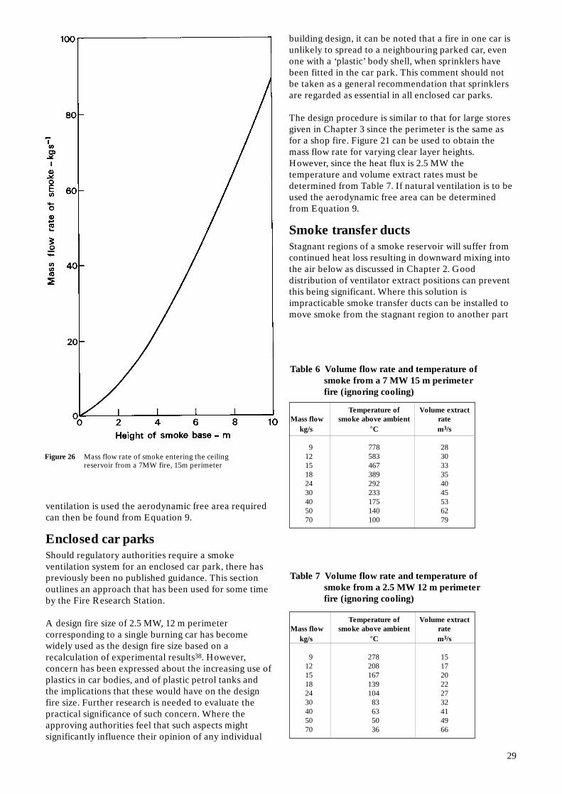
Table 6 Volume flow rate and temperature ofsmoke from a 7 MW 15 m perimeterfire (ignoring cooling)
Temperature of Volume extractMass flow smoke above ambient rate
kg/s °C m3/s
9 778 2812 583 3015 467 3318 389 3524 292 4030 233 4540 175 5350 140 6270 100 79
Table 7 Volume flow rate and temperature ofsmoke from a 2.5 MW 12 m perimeterfire (ignoring cooling)
Temperature of Volume extractMass flow smoke above ambient rate
kg/s °C m3/s
9 278 1512 208 1715 167 2018 139 2224 104 2730 83 3240 63 4150 50 4970 36 66
Figure 26 Mass flow rate of smoke entering the ceilingreservoir from a 7MW fire, 15m perimeter
ventilation is used the aerodynamic free area requiredcan then be found from Equation 9.
Enclosed car parksShould regulatory authorities require a smokeventilation system for an enclosed car park, there haspreviously been no published guidance. This sectionoutlines an approach that has been used for some timeby the Fire Research Station.
A design fire size of 2.5 MW, 12 m perimetercorresponding to a single burning car has becomewidely used as the design fire size based on arecalculation of experimental results38. However,concern has been expressed about the increasing use ofplastics in car bodies, and of plastic petrol tanks andthe implications that these would have on the designfire size. Further research is needed to evaluate thepractical significance of such concern. Where theapproving authorities feel that such aspects mightsignificantly influence their opinion of any individual
building design, it can be noted that a fire in one car isunlikely to spread to a neighbouring parked car, evenone with a ‘plastic’ body shell, when sprinklers havebeen fitted in the car park. This comment should notbe taken as a general recommendation that sprinklersare regarded as essential in all enclosed car parks.
The design procedure is similar to that for large storesgiven in Chapter 3 since the perimeter is the same asfor a shop fire. Figure 21 can be used to obtain themass flow rate for varying clear layer heights.However, since the heat flux is 2.5 MW thetemperature and volume extract rates must bedetermined from Table 7. If natural ventilation is to beused the aerodynamic free area can be determinedfrom Equation 9.
Smoke transfer ductsStagnant regions of a smoke reservoir will suffer fromcontinued heat loss resulting in downward mixing intothe air below as discussed in Chapter 2. Gooddistribution of ventilator extract positions can preventthis being significant. Where this solution isimpracticable smoke transfer ducts can be installed tomove smoke from the stagnant region to another part
29

Figure 27 Use of smoke transfer ducts in otherwise stagnant regions
of the smoke reservoir to rise with an existing flowtowards a vent or extract fan (Figure 27).
As a ‘rule of thumb’, if the reservoir continues morethan 3 times as deep beyond an extract opening as thereservoir is wide, then a smoke transfer duct may benecessary. A currently recommended value of theminimum extract rate is 4% of the smoke layer’s netflow or 1 m3/s, whichever is the greater.
Entrances within the smoke layerThere have been shopping centres designed withentrances within the smoke layer (eg from car parksabove the shopping levels). Any pedestrian area insidethese entrances and open to the mall needs to be smallenough to be evacuated quickly through smoke sealeddoors.
Other situationsThe possibilities for special features are by no meansexhausted by the above. Whenever another specialcase occurs that is not explicitly covered by thisReport, advice should be sought from experts.
30

All reservoir screens, smoke channelling screens andnatural vents that are not permanent features shouldoperate automatically, actuated by smoke detectors, asshould mechanical extract systems. Other types ofdetector are less useful since, at best, they have longerresponse times and many (eg fusible links) may notoperate at all. It is much easier to prevent smokespreading to escape routes than it is to clear suchroutes subsequently. If doors are to be relied on as airinlets, devices to open them automatically are needed.
When non-permanent automatic drop curtains areused as reservoir screens the gaps between curtainsshould be minimised. If a powered smoke extractsystem is installed, care should be taken to ensure thatsmoke leakage through gaps between curtains does notinadvertently activate adjacent powered extract zones.It can be an advantage to open all the natural ventsinstalled in a shopping centre, since those in zonesunaffected by smoke can contribute to the fresh airinflow. Wherever it is feared that wind pressures onvents to unaffected reservoirs may be much morenegative than on vents in a smoke-filled reservoir, it isrecommended that wind-tunnel studies and/or adetailed pressure analysis be carried out to evaluatethe effect on venting efficiency. When mechanicalextraction is used for a number of separate smokereservoirs, it would be better to operate the smokecontrol system individually by zones. Facilities formanual override should be installed to allow greaterflexibility in firefighting, testing and maintenance.
The normal ventilation systems fitted to many, if notmost, malls and shops blow air into the mall or shop at
Chapter 5Some operational factors
a high level, frequently where smoke would be flowing.This air would simply increase the quantity of smokethat has to be dealt with. Hence the normal ventilationinlet system should be automatically shut down whensmoke is detected.
If the smoke to be removed from a reservoir is too hotfor the ducting or for the fans, sprinklers or water jetscould be installed in a suitable part of the extractducting to cool the smoke. A temperature ratingquoted for many (but not all) smoke extract fans is tosurvive a temperature of 300°C for half an hour. Manyauthorities regard this time as sufficient for escapefrom most malls — but note that this should not beregarded as being universally true. All such criteriashould be agreed with the approving authorities. Allelectrical apparatus and power supply cables used inthese smoke ventilation systems should, of course, beprotected to ensure sustained operation in a fire. Cold smoke tests are sometimes used for theacceptance testing of smoke ventilation systems.Whilst this cold smoke can be used to operate thesmoke detection system and therefore activate all thecomponents of the smoke ventilation system, it shouldbe noted that since the smoke is cold it would not havethe buoyancy that smoke in a true fire condition wouldhave, and cannot therefore adequately test theventilation efficiency of the system.
Smoke ventilation systems should be regularly testedand adequately maintained.
31

References
1 Home Office and Scottish Home and HealthDepartment. Fire precautions in town centreredevelopment. Fire Prevention Guide 1. London,HMSO, 1972.
2 British Standards Institution. Fire precautions inthe design and construction of buildings. Code ofpractice for shops. British Standard BS 5588: Part2: 1985. London, BSI, 1985.
3 Canter D. Studies of human behaviour in fire:empirical results and their implications foreducation and design. Building ResearchEstablishment Report. Garston, BRE, 1985.
4 Morgan H P. Smoke control methods in enclosedshopping complexes of one or more storeys: adesign summary. Building Research EstablishmentReport. London, HMSO, 1979.
5 British Standards Institution. Fire precautions inthe design and construction of buildings. Part 10:Code of practice for enclosed shopping complexes.British Standard BS 5588: Part 10. London, BSI. Tobe published.
6 Heselden A J M. Fire problems of pedestrianprecincts. Part 1. The smoke production of variousmaterials. Fire Research Station Fire Research Note856, Borehamwood, BRE, 1971.
7 McGuire J H, Tamura G T and Wilson A G.Considerations in the design of smoke controlsystems in tall buildings. Proceedings of ASHRAESymposium on Fire Hazards in Buildings,San Francisco, January 1970.
8 Hinkley P L. Work by the Fire Research Stationon the control of smoke in covered shoppingcentres. Building Research Establishment CurrentPaper CP83/75, Borehamwood, BRE, 1975.
9 London Transport Board. Second Report of theOperational Research Team on the capacity offootways. Research Report 95.
10 Heselden A J M and Hinkley P L. Smoke travel inshopping malls. Experiments in co-operation withGlasgow Fire Brigade — Part 1. Fire ResearchStation Fire Research Note 832, Borehamwood,BRE, 1970.
11 Silcock A and Hinkley P L. Fire at Wulfrunshopping centre, Wolverhampton. Fire ResearchStation Fire Research Note 878, Borehamwood,BRE, 1971.
32
12 Thomas P H et al. Investigations into the flow ofhot gases in roof venting. Fire Research TechnicalPaper No 7, London, HMSO, 1963.
13 Morgan H P and Chandler S E. Fire sizes andsprinkler effectiveness in shopping complexes andretail premises. Fire Surveyor, 1981, 10 (5) 23–28.
14 Gardner J P. Unsprinklered shopping centres.Design fire sizes for smoke ventilation. FireSurveyor, 1988, 17 (6) 41-47.
15 Hinkley P L. Rates of production of hot gases inroof venting experiments. Fire Safety Journal,1986, 10 57–65.
16 Heselden A J M, Wraight H G H and Watts P R.Fire problems of pedestrian precincts. Part 2.Large-scale experiments with a shaft vent. FireResearch Station Fire Research Note 954,Borehamwood, BRE, 1971.
17 Morgan H P, Marshall N R and Goldstone B M.Smoke hazards in covered multi-level shoppingmalls: some studies using a model two-storey mall.Building Research Establishment Current PaperCP45/76, Borehamwood, BRE, 1976.
18 Hansell G O, Marshall N R and Morgan H P.Private communication. Fire Research Station1988.
19 Morgan H P. The horizontal flow of buoyant gasestoward an opening. Fire Safety Journal, 1986, 11,193–200.
20 Morgan H P and Marshall N R. Smoke hazards incovered, multi-level shopping malls: anexperimentally-based theory for smokeproduction. Building Research EstablishmentCurrent Paper CP48/75, Borehamwood, BRE,1975.
21 Morgan H P and Marshall N R. Smoke controlmeasures in covered two-storey shopping mallhaving balconies as pedestrian walkways. BuildingResearch Establishment Current Paper CP11/79,Borehamwood, BRE, 1979.
22 Morgan H P and Hansell G O. Atrium buildings:calculating smoke flows in atria for smoke controldesign. Fire Safety Journal, 1987, 12 (1) 9–35.
23 Hansell G O, Morgan H P and Marshall N. Smokeflow experiments in a model atrium: Part 2 plumeentrainment in the atrium. To be published.
24 Thomas P H. On the upward movement of smokeand related shopping mall problems. Fire SafetyJournal, 1987, 12 (3) 191–203.
25 Morgan H P. Comments on ‘A note on smokeplumes from fires in multi-level shopping malls’.Fire Safety Journal, 1987, 12 (1) 83–84.
26 Law M. A note on smoke plumes from fires inmulti-level shopping malls. Fire Safety Journal,1986, 10 197–202.
27 Morgan H P and Marshall N R. The depth of void-edge screens in shopping malls. Fire EngineersJournal, 1989, 48 (152) 7–9.
28 Hansell G O. Fire Engineers Journal, 1989, 48(152) 9.
29 Penwarden A D. Acceptable wind speeds in town.Building Research Establishment Current PaperCP1/74, Garston, BRE, 1974.
30 Spratt D and Heselden A J M. Efficient extractionof smoke from a thin layer under a ceiling. FireResearch Station Fire Research Note 1001,Borehamwood, BRE, 1974.
31 Heselden A J M. Private communication. FireResearch Station, 1976.
32 Chartered Institution of Building ServicesEngineers. CIBSE Guide, Volume C, 1986.
33 Marshall N R and Heselden A J M. Smoke controlin large stores opening onto enclosed shoppingmalls. Fire Surveyor, 1986, 15 (1) 18–22.
34 Morgan H P and Savage N P. A study of a largefire in a covered shopping complex: St John’sCentre 1977. Building Research EstablishmentCurrent Paper CP10/80, Borehamwood, BRE 1980.
35 Hansell G O and Morgan H P. Fire sizes in hotelbedrooms — implications for smoke controldesign. Fire Safety Journal, 1985, 8 (3) 177–186.
36 Morgan H P and Hansell G O. Fire sizes andsprinkler effectiveness in offices — implications forsmoke control design. Fire Safety Journal, 1985, 8(3) 187–198.
37 Marshall N R, Feng S Q and Morgan H P. Theinfluence of a perforated false ceiling on theperformance of smoke ventilation systems. FireSafety Journal, 1985, 8 (3) 227–237.
38 Butcher E G, Langdon-Thomas G J andBedford G K. Fire and car park buildings. FireResearch Station Fire Note 10, Borehamwood,BRE, 1968.
33

Liaison Panel
The preparation of the final report was undertaken with the assistance of a Liaison Panel whichconsisted of the following members, representing both industry and Government interests:
Department of the Environment, Construction DirectorateHome Office, Fire InspectorateScottish Development DepartmentColt International LimitedGradwood LimitedNuaire Limited
34

Also available from BRE
Smoke control in buildings: design principlesBRE Digest 396 £4.50Outlines the design principles for systems which will providesafe escape routes from buildings.
Fire spread in buildings BRE Information Paper IP21/84 £3.50This paper is concerned with the spread of fire in occupiedbuildings and its implications for safety of life. It makessuggestions on how problems are avoided.
Smoke spread within buildingsBRE Information Paper IP22/84 £3.50 Complementary to Fire spread in buildings, IP21/84, thispaper is concerned with smoke spread to areas beyond thesource, its implications for life safety and for propertydamage.
Fire safety in buildings Ref BR96 £16 BRE Report 1986 The author’s view of how Building Regulations and fireprotection measures relate to actual fires. The Reportmakes a number of suggestions for the improvement ofprotection measures and its legislation.
Aspects of fire precautions in buildingsRef BR137 £16 BRE Report 1988 This book introduces students and others to the passiveaspects of fire precautions—the measures taken andprotection provided in a building, for example, to minimisethe risk to occupants, contents and structure from anoutbreak of fire. It describes the nature of fire, structural fireprotection techniques and means of escape.
Selection of sprinklers for high rack storage inwarehouses BRE Information Paper IP5/88 £3.50 Demonstrates the likely benefits of a ‘fast-response’ solder-link sprinkler head for use in a warehouse. A ‘fast-response’solder-link sprinkler has been shown to provide effective in-rack protection for goods stored in high racks up to about10 m. The information will be useful to manufacturers, thoseconcerned with high rack storage, insurers and the fireauthorities.
Guidelines for the construction of fire-resistingstructural elements Ref BR128 £13 BRE Report 1988 This Report establishes guidelines for the fire resistance ofelements of structure. It includes tables of notional periodsof fire resistance based on current test data; it also makesrevisions to tables and text concerning concrete, masonryand timber included in the earlier 1982 edition.
ASKFRS Part 1 The scientific content Part 2 A programmer’s guide BRE Computer package AP46 £100.00 + £17.50 VAT An interactive computer program comprising a manual and511/40 disk, to help fire engineers quantify various firescenarios using common algebraic expressions and amaterials database. Part 1 provides ten types ofcalculation—Part 2 describes ASKFRS. The program iswritten in FORTRAN-77 and can be run on various VAXcomputers and IBM PCs.
Experimental programme to investigateinformative fire warning characteristics formotivating fast evacuation Ref BR172 £30 BRE Report 1990 Gives details of an experimental programme to evaluate therelative effectiveness of alarm bells, text messages,computer generated voice and graphics displays to motivateescape. The quantitative values of each, in promoting adecision to escape, are given together with the subjects’message assimilation times.
Psychological aspects of informative fire warningsystems Ref BR127 £9 BRE Report 1988 A summary of research using simulations of informative firewarning systems in a number of buildings, and how theinformation they carried, and training procedures, can mosteffectively promote rapid and safe evacuation in the eventof fire.
Studies of human behaviour in fire: empiricalresults and their implications for education anddesign Ref BR61 £11 BRE Report 1985 A model of human behaviour in fire is presented. Theimplications of the model and the findings of the variousstudies are discussed in relation to education, training,publicity, design and legislation. Essential reading for allthose involved in decision making in these fields.