design provisions for sodium inventory … documents... · for a loop type reactor heat exchangers...
TRANSCRIPT

DESIGN PROVISIONS FOR SODIUM INVENTORY CONTROL IN FBR
B. Anoop, S. Athmalingam, S. Raghupathy & P. Puthiyavinayagam
Indira Gandhi Centre for Atomic Research
Department of Atomic Energy
Kalpakkam-603102, India
First IAEA Workshop on Challenges for Coolants in Fast Spectrum System : Chemistry and Materials5 – 7 July 2017
CONTENTS
Sodium systems and inventory requirement
Regulation of inventory
Prevention and mitigation of sodium leak
INTRODUCTION
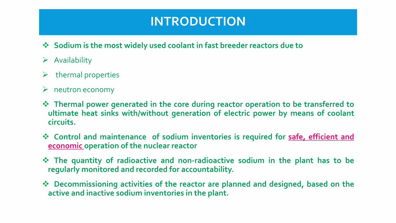
Sodium is the most widely used coolant in fast breeder reactors due to
Availability
thermal properties
neutron economy
Thermal power generated in the core during reactor operation to be transferred toultimate heat sinks with/without generation of electric power by means of coolantcircuits.
Control and maintenance of sodium inventories is required for safe, efficient andeconomic operation of the nuclear reactor
The quantity of radioactive and non-radioactive sodium in the plant has to beregularly monitored and recorded for accountability.
Decommissioning activities of the reactor are planned and designed, based on theactive and inactive sodium inventories in the plant.
COOLANT SYSTEMS FOR FBR
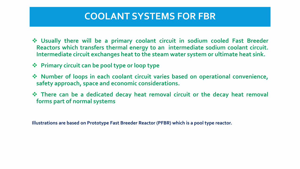
Usually there will be a primary coolant circuit in sodium cooled Fast BreederReactors which transfers thermal energy to an intermediate sodium coolant circuit.Intermediate circuit exchanges heat to the steam water system or ultimate heat sink.
Primary circuit can be pool type or loop type
Number of loops in each coolant circuit varies based on operational convenience,safety approach, space and economic considerations.
There can be a dedicated decay heat removal circuit or the decay heat removalforms part of normal systems
Illustrations are based on Prototype Fast Breeder Reactor (PFBR) which is a pool type reactor.
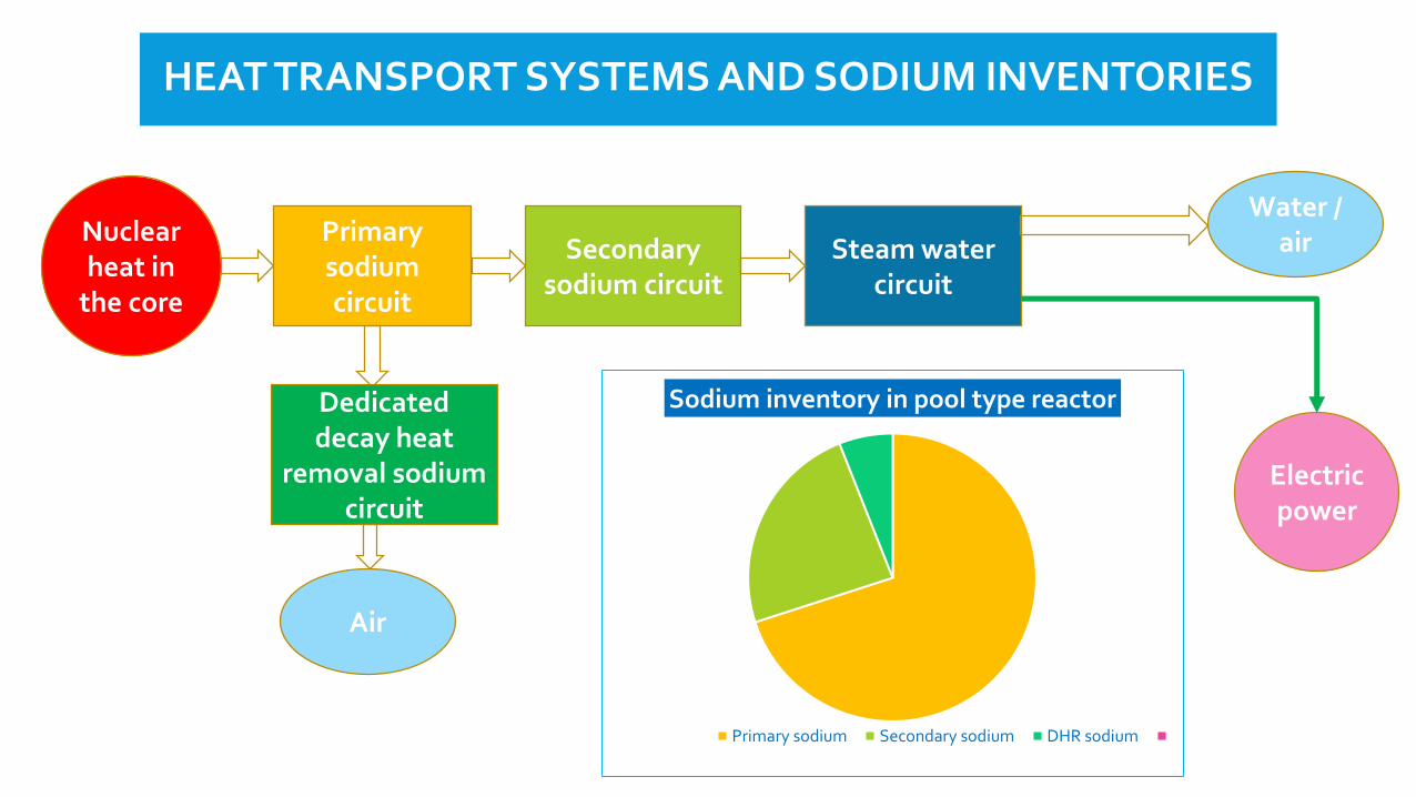
HEAT TRANSPORT SYSTEMS AND SODIUM INVENTORIES
Nuclear heat in
the core
Primary sodium circuit
Secondarysodium circuit
Steam water circuit
Water / air
Electric power
Dedicated decay heat
removal sodium circuit
Air
Sodium inventory in pool type reactor
Primary sodium Secondary sodium DHR sodium
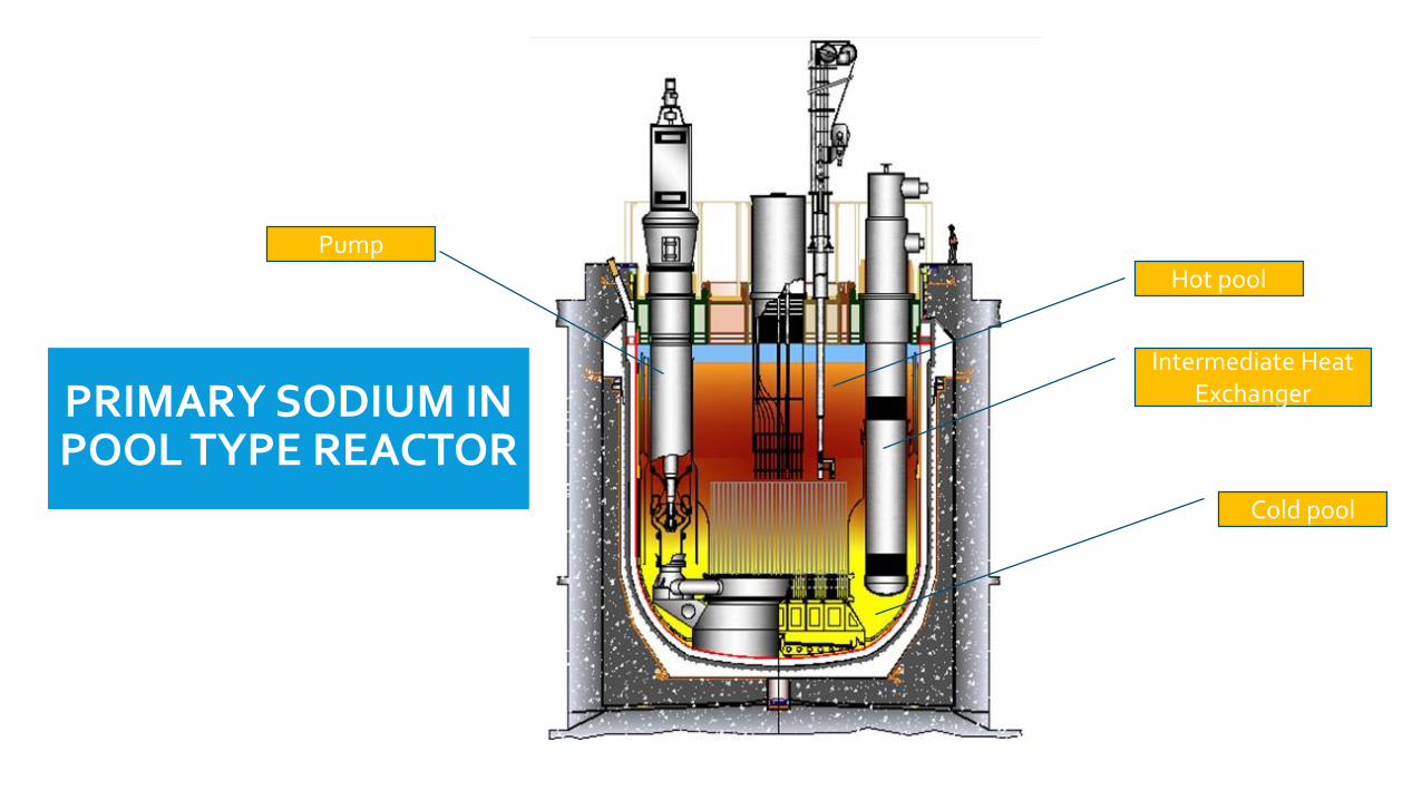
PRIMARY SODIUM IN POOL TYPE REACTOR
Intermediate Heat Exchanger
Cold pool
Pump
Hot pool

PRIMARY SODIUM CIRCUIT – SODIUM INVENTORY
For a pool type reactor : reactor core, intermediate heat exchanger (IHX), decay heatexchanger (DHX) and primary sodium pumps are immersed in primary sodium filled inmain vessel.
Height of the primary sodium in main vessel is decided by the height of inletwindows of the heat exchangers with margin to avoid gas entrainment.
Diameter of main vessel is decided by that required to accommodate all thecomponents of reactor assembly and heat transport systems.
Hence, sodium inventory in main vessel is decided by its diameter and height ofsodium pool.
For a loop type reactor heat exchangers and pumps are external to the reactor vesseland connected with piping. Sodium inventory is decided by volume of vessels, heatexchangers and piping.
Variations in bulk density of sodium under various operating conditions areconsidered in filling height of sodium in main vessel.
Sodium inventory in purification systems are added in total inventory filled.
SECONDARY SODIUM CIRCUIT – SODIUM INVENTORY
Sodium inventory in secondary sodium loop is governed by
Number of loops
Heat transfer capacity of the loop
Position of components in the loop
Inventory in auxiliary circuits like fill and drain, purification and SG Tube leakdetection
Sodium inventory in secondary circuit is decided by that filled incomponents and piping of these circuits and sodium level maintained in theconnected secondary sodium storage tanks to which sodium is drained.
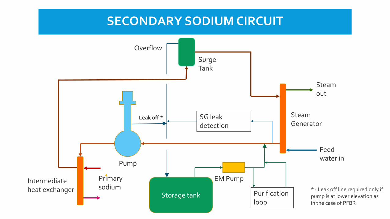
Storage tank Purification loop
SG leak detection
Feed water in
Steam out
Steam Generator
Surge Tank
Pump
Intermediate heat exchanger
Primary sodium
Leak off *
Overflow
EM Pump
SECONDARY SODIUM CIRCUIT
* : Leak off line required only if pump is at lower elevation as in the case of PFBR

DECAY HEAT REMOVAL CIRCUIT – SODIUM INVENTORY
There can be a dedicated decay heat removal (DHR) system or decay heatremoval can be performed by normal heat removal system
Multiple loops can be provided to enhance availability of the system
Capacity of each loop is decided by the maximum decay power to beremoved from the reactor assuming unavailability of one loop
Sodium inventory is governed by
Heat transfer capacity of the loop
Elevation difference between thermal centres in the loop in case of natural circulationloop
Inventory in auxiliary circuits like fill and drain & purification
Sodium inventory in DHR circuit is decided by that filled in components andpiping of the loops

Storage tank
Purification loop
Air out
Air Heat exchanger
Expansion Tank
Decay heat exchanger
Primary sodium
EM Pump
DECAY HEAT REMOVAL CIRCUIT
Air in
INVENTORY REGULATION : PRIMARY CIRCUIT
For pool type reactor : Continuous and discontinuous level probes in hot pooland cold pool. Three important levels in hot pool are
High level : To detect leak of secondary sodium / DHR loop sodium to primary sodium
Fill level : Used for initial filling of sodium in main vessel
Low level : Top of IHX window - Sodium level required for heat transfer
Low level in secondary sodium storage tank or DHR expansion tank will giveearly indication for leak through IHX or DHX.
Cold pool level probes gives alarm if level is below fuel subassembly top.
For loop type reactor, individual levels in reactor vessel, pump tank andstorage tank are monitored.

For secondary sodium loop of fixed volume, the highest level of sodium is the surgetank and overflow line is provided in surge tank to send excess sodium in the loop tothe storage tank.
Storage tank and the loop in connected during operation.
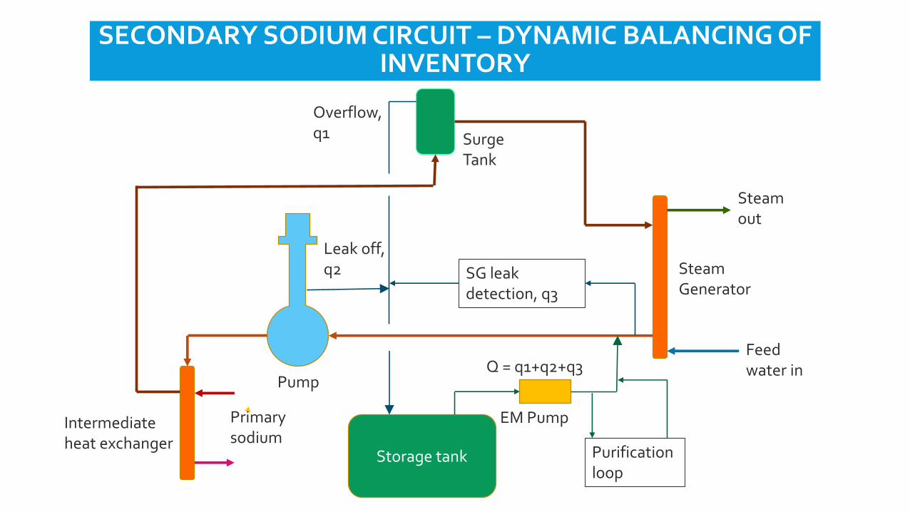
During operation of the secondary sodium circuit, there will be a continuous loss ofinventory from the loop to the storage tanks due to leak of flow through secondarysodium pump labyrinths if the pump is at lower elevation in the cold leg and smallsampling flow through SG leak detection system.
To make up the losses, sodium is continuously fed into the secondary sodium loopby an electromagnetic (EM) pump from the storage tank
For an effective control of inventory in secondary sodium loop, the EM pumpinjection rate is sufficiently excess to the total expected drain rate from the systemconsidering all states of operation and the excess sodium injected into the loop isreturned to the storage tank though the overflow pipeline of surge tank connecting tothe storage tank.
A small quantity of sodium remains in the secondary storage tank to enable sodiumcirculation through the fill and drain lines
SECONDARY SODIUM CIRCUIT – DYNAMIC BALANCING OF INVENTORY
Storage tank Purification loop
SG leak detection, q3
Feed water in
Steam out
Steam Generator
Surge Tank
Pump
Intermediate heat exchanger
Primary sodium
Q = q1+q2+q3
Leak off, q2
Overflow, q1
EM Pump
SECONDARY SODIUM CIRCUIT – DYNAMIC BALANCING OF INVENTORY

INVENTORY REGULATION : SECONDARY CIRCUIT
Mutual inductance type continuous level probes and discontinuous levelswitches are provided in the system tanks.
Surge tank is at the highest elevation in the system and level switches forhigh, normal and low levels are provided. In addition to the alarmannunciation, the high and low levels in surge tank will trip the secondarysodium pump.
Low and fill level switches are provided in storage tank and low level switchtrips secondary sodium main pump and the EM pump.
Any overall leak from the system is detected by continuous level probe in thestorage tank when sodium is below the set point.
Low and high level are provided in the pump tank. The discontinuous levelswitches give interlock to trip the sodium main pump.
INVENTORY REGULATION : DHR CIRCUIT
The sodium is filled in the loop up to the specified level in the expansion tank of the loop, which is situated at the highest elevation.
Once filled, the loop is isolated from the storage tank and sodium inventory in the loop is maintained.
Mutual inductance type continuous and discontinuous level probes in the expansion tank and storage tank. Discontinuous level switches indicate high level, fill level and low levels.
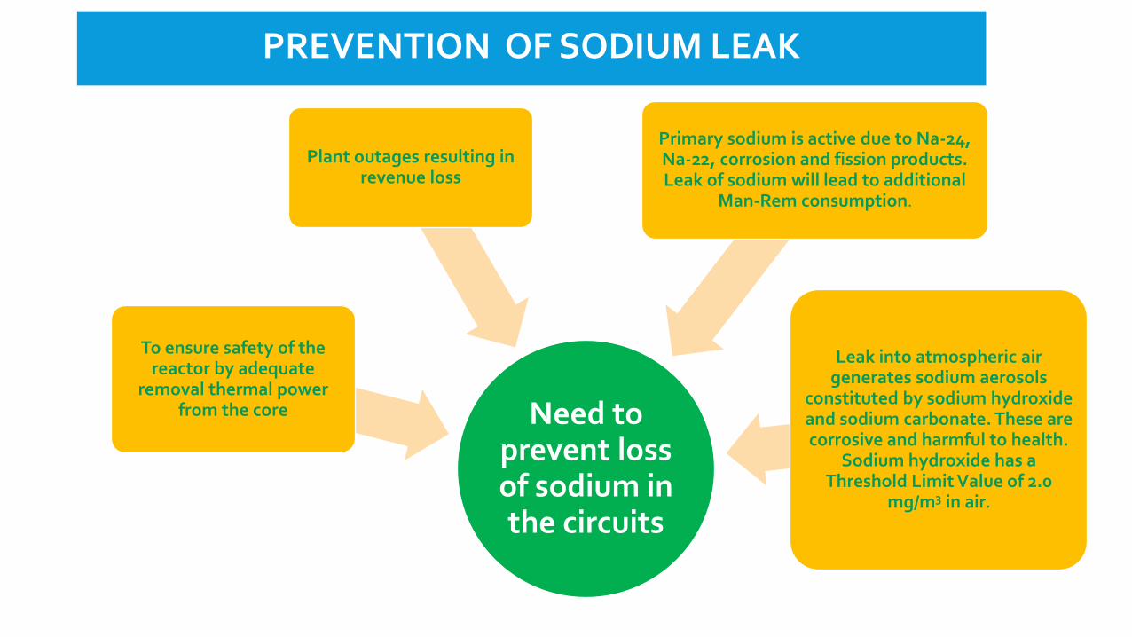
Need to prevent loss of sodium in the circuits
To ensure safety of the reactor by adequate
removal thermal power from the core
Plant outages resulting in revenue loss
Primary sodium is active due to Na-24, Na-22, corrosion and fission products. Leak of sodium will lead to additional
Man-Rem consumption.
Leak into atmospheric air generates sodium aerosols
constituted by sodium hydroxide and sodium carbonate. These are corrosive and harmful to health.
Sodium hydroxide has a Threshold Limit Value of 2.0
mg/m3 in air.
PREVENTION OF SODIUM LEAK

PROVISIONS TO PREVENT SODIUM LEAK
Stringent design and manufacturing procedures are followed for sodium systems of a fast breeder reactor.
Sodium systems important for safety are designed and manufactured according tohighest safety class as per stringent nuclear codes. Systems undergo detailed designanalysis.
Material of construction selected for sodium systems are based on wide experience andmaximum expected service conditions
Stringent specification for fabrication and erection of sodium systems with proper qualitycontrol, qualification of fabrication procedure, all welded construction, volumetric andsurface inspections, integrity testing, helium leak testing etc.
ENGINEERED FEATURES FOR MITIGATION OF LOSS OF INVENTORY
In a pool type reactor full inventory of primary sodium is in the reactor vesseland the core is always submerged in primary coolant.
A safety vessel around main vessel can be provided to contain the primarysodium in case of a leak for both pool type and loop type reactors.
The gap between safety vessel and main vessel is restricted such that even incase of a main vessel leak, the limited volume between main vessel & safetyvessel restricts fall in sodium level such that sodium circulation through heatexchangers are ensured.
For a loop type reactor, siphon break arrangement is provided in the pipingconnected to primary sodium in the reactor vessel. This will prevent drainingof sodium below a safe level in the reactor vessel.
ENGINEERED FEATURES FOR MITIGATION OF LOSS OF INVENTORY
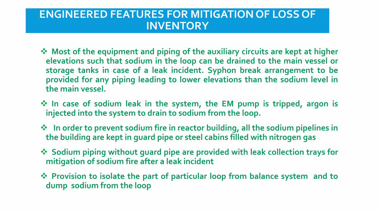
Most of the equipment and piping of the auxiliary circuits are kept at higherelevations such that sodium in the loop can be drained to the main vessel orstorage tanks in case of a leak incident. Syphon break arrangement to beprovided for any piping leading to lower elevations than the sodium level inthe main vessel.
In case of sodium leak in the system, the EM pump is tripped, argon isinjected into the system to drain to sodium from the loop.
In order to prevent sodium fire in reactor building, all the sodium pipelines inthe building are kept in guard pipe or steel cabins filled with nitrogen gas
Sodium piping without guard pipe are provided with leak collection trays formitigation of sodium fire after a leak incident
Provision to isolate the part of particular loop from balance system and todump sodium from the loop
LEAK DETECTION
System to be designed for an early detection and mitigation of sodium leakand loss of inventory.
Leak before break approach is followed in the design of large piping andcomponents to enable leak detection before catastrophic failure of the system
Sodium leak detectors required to be placed external to all sodium systempiping and components which gives alarm in the main control room as well aslocal control centres seeking urgent operator action
Diverse and redundant leak detectors based on different principles are used .
Spark plug leak detector
Mutual inductance leak detector
Wire type leak detector
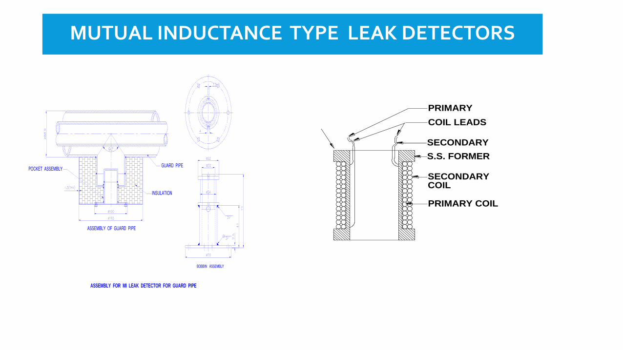
MUTUAL INDUCTANCE TYPE LEAK DETECTORS
ASSEMBLY FOR MI LEAK DETECTOR FOR GUARD PIPE
SECONDARY
S.S. FORMER
SECONDARY
PRIMARY COIL
COIL LEADS
COIL
PRIMARY
DOUBLE ENVELOPE
SODIUM PIPE
Py. & Sy. Windings
FIG.6: MUTUAL INDUCTANCE TYPE LEAK DETECTOR
2 METERS

WIRE TYPE LEAK DETECTORS
CERAMIC BEAD NICKEL WIRE
SS Binding
SS Pipe
Na Wire Type Leak
Detector
Heater Wire
Glass Wool
Insulation
Al. Cladding
Thermocouple
LEAK DETECTION
Sodium aerosol detector are provided near to the piping and components insteam generator buildings for leak detection.
Sodium leak in steam generators tubes will result in sodium water reaction.Continuous sampling of sodium at the outlet of all the Steam Generators isdone to detect hydrogen evolved due to any leak in SG tube bundle. Nickeltube detectors and Electrochemical hydrogen meters are used hydrogen insodium detection. Thermal conductivity detectors are used in cover gas forhydrogen detection at lower temperature.
Indirect methods like rise / fall in sodium level in the tanks will also help inleak detection.
Sodium leaking due to valve passing into storage tank for a normallyisolated loop will be detected by level rise in the tank.

SG TUBE LEAK DETECTOR – HYDROGEN IN SODIUM
ELECTRONICS
MILLI TORR
GAUGESTD H2
LEAK
SO
RP
TIO
N
PU
MP
SPUTTER
ION
PUMP
MHEATER
ELECTRO
CHEMICAL
HYDROGEN
METER
ECHM
ELECTRO-
NICS
EC
HM

MAKE UP FOR LOSS OF INVENTORY
Any significant sodium loss in the system due to leak will be replenishedfrom the reserve sodium storage.
Sodium loss due to that sticking on the components taken out formaintenance and spent subassemblies immersed in primary sodium to bereplenished periodically.
Additional quantity of sodium is filled in the DHR loop considering the loss of inventory through seat leakage of isolation valves to storage tank. The additional quantity is for operation between two fuel handling campaigns including the DHR period.
Make up is done by means of EM pumps or pressurization method from the storage tanks.
SUMMARY
Quantity of sodium in heat transport circuits decided by thermal power andsystem configuration
Effective heat removal from the core can be impaired due loss of sodiumfrom the heat transport sodium circuits which affects safety in operation ofthe reactor.
Redundant and diverse instrumentation have to be provided for monitoringsodium level and for leak detection
Engineered safety features for prevention and mitigation of leak
The sodium inventory control and accountability of radioactive and non-radioactive sodium is necessary for planning and design of decommissioningactivities of the plant after the service life.

THANK YOU FOR KIND ATTENTION