design specifications - academy pendulum sales
TRANSCRIPT

1
Revised as of 3/26/2011

2
Mark 2 Foucault pendulum
Index Page
General information ------------------------------------ 3 Specifications ------------------------------------------- 6 Tower Drawing ----------------------------------------- 7 Ball Drawing ------------------------------------------- 8 Mounting platform details --------------------------- 9 Typical floor mount ----------------------------------- 10 Typical hanging mount ------------------------------- 11 Typical wiring schematic ---------------------------- 12 Designers swing chart -------------------------------- 13 Notes ---------------------------------------------------- 14

3
Architectural specifications For the
Mark 2 Foucault Pendulum Kit by
Academy Pendulum Sales
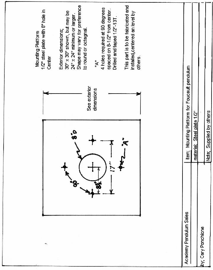
The Mark 2 Foucault Pendulum blends art and science into a stunning display. The 235lb mirror finished brass ball accents this display while swings slowly across the pit demonstrating the Earth’s rotation. APS pendulums are easy to install, and will give many years of service with little or no maintenance required. A small amount of electrical power is required to maintain continuous operation. Pendulum Kits; Each pendulum kit contains the following; 1, A 235lb. all brass ball with sculptured end caps. The lower cap contains an adjustable ½” brass pin which may be adjusted to knock down pins, or when replaced with a magnet can operate sensors in the floor. 2, A magnet drive system to keep the ball in motion. 3, An electronic control system to operate the magnet, and control the swing distance of the ball. The control system contains two parts. The control panel and the logic panel. 4, A safety device contains the cable and upper components should the cable suffer a catastrophic failure. (which has not occurred in the 50+ years of production.). 5, 2- 1/8” suspension cables. Included is 1 spare cable. 6, An installation tool used to set the ball onto the cable. 7, One 14”h x 10”w brass educational wall plaque with Walnut base. 8, Installation and owners manuals 9, Smoke shields to enclose the unit for fire safety. Prerequisites; To install a pendulum requires a few details be completed during the construction or remodeling of the building. A proper mounting platform (not supplied by APS) must be designed constructed and installed into the building. Some built in electrical requirements must be attended to for the control panel and logic panel to be installed. The mounting platform (mp); The mp is a ½” steel plate measuring 30” (either square, round or octagon in shape). It is to have an 8” hole in the center, and 4 drilled and tapped ½ x 13t holes placed 90 degrees apart on a 8 ½” radius from the center. The Pendulum requires a clear space of 42” directly above the center of the mounting platform for the adjusting bolt and cable. This mounting platform should be mounted solidly to the building, leveled and centered over the pit. The mp should be mounted to the building with the ability to support a 500lb. live load. It should be braced to eliminate the side torque generated by the balls 235lb. swinging mass at the swing distance of 5 degrees from center. Speed of the balls swing will depend on the length of the cable. The bottom of the mp may be sealed to a floor or ceiling (except for the center hole) to keep smoke from traveling upward as required by some city fire codes. (continued)

4
The pendulum base and tower have anti-draft shield to keep smoke from traveling through the pendulum itself. Electrical requirements; For ease of adjustments, the control panel should be mounted in an area where the onboard tone device may be turned on and heard while viewing the ball, or the cable. The control panel box measures 12”h x10”w x 4”d and may be supplied ahead of the pendulums arrival (upon request) with either surface or flush mount as required for your installation. Power requirements; 120VAC 60htz.at 100 watts is required at the control panel only. 1 or 2 additional conduits (depending on the electrical codes for your area) must be installed from the control panel box to the tower area. They should terminate in a “J” box located within 3ft. of the mounting platform. A 6’ length of ½” flexible conduit should be added to the ‘J” box with a ½”connector on the end of the flex cable. The wires should extend 12” beyond the fitting so a connection may be made to the logic panel box when installed. The logic panel is normally mounted onto the tower, but may be mounted remotely. Wiring between the control panel and the logic panel; See page 10 for typical wiring layout. From the control panel to the Logic panel require three color coded #14. wires plus a ground wire are required, and 1pr. shielded #18ga. A cable such as the Alpha brand # 2471 cable with a 600VAC insulation is a good choice, and my occupy the same conduit as the 120VAC in most installations, The #14 wires will conduct the 120VAC (which is switched and fused at the control panel) to the logic panel at the tower. The shielded pr. is for the timing control of the logic module. See Page 13 for remote mounting details. Pendulum magnet and suspension tower assembly; The assembled magnet and tower assy. measure 36”h x 18”w This unit is equipped with metal shields to aide in smoke and fire suppression. The magnet and mounting ring are supplied as an assembly, as is the tower cone. Note; In areas that sustain high temperatures such as glass skylights or hot attic spaces, the logic panel may be relocated up to 50’ away from the tower. Install 2 #14 thhn, and 2 shielded pairs between the logic panel and the tower. Swing specifications; The height will determine the period of time for the swing. It will also govern the distance of the swing. The Mark 2 pendulum has a maximum swing angle of 5 degrees from center, and a minimum swing angle of 2 degrees from center. To calculate the distance of swing multiply the height (in inches) times the tangent of the angle from center. For 5 degrees the tangent is .08745. to calculate for a 50’ pendulum (600”) you would have 600 x .08745= a radius of 52.49” x2 = diam. Of 105” total swing. An additional 12” for over swing, and 15” for the diameter of the ball. = 132” total swing to the outside of the ball. I suggest railings be at least 3’ from the ball to keep unwanted grabbing of the cable.

5
Installation information; The mounting platform and electrical should be installed during the construction phase. An average of 2 to 3 man days is required to assemble and complete the installation of the Foucault pendulum depending upon the difficulty of getting to the tower site. It will require 2 men to move the heavier components like the magnet and the ball. The ball in its crate weighs 290lbs. A special mounting fixture is supplied to aide in the installation of the ball. Installation Information Continued; Installation requires; assembly, leveling, centering, connecting wires, and adjusting controls on control panel. Shipping; The shipment will be 1 pallet of 4crates with a total weight of 640lbs. Shipping is class 70 freight, and is usually shipped by truck or sea. Limited Warranty; Each pendulum is set up and tested before crating. The parts in this product are warranted for a period of 1 year from the date of acceptance of the building, or (in completed buildings) from the date of first usage. The warranty covers parts and defects, but does not cover on site labor. Trouble shooting assistance by phone or Email is always free. Purchasing a Foucault Pendulum within the USA; It is always advisable to contact your seller early when considering the installation of a Foucault pendulum. With 30 years of experience our free consultation often proves helpful in making decisions on mountings, site access and accoutrements for the floor. Ordering a pendulum requires a purchase order accompanied by a down payment of 50% of the selling price and a signed and dated bid proposal. Bid proposals available on line at: <[email protected]> Buying a unit from stock may still require machining of the magnet bore to meet the swing specifications for your particular building dimensions. Allow at least 10 weeks for construction (after we receive the required dimensions for the machining), assembling, testing, and crating process. Shipping within the USA may require up to 2 weeks by truck. International shipping will require much longer due to customs etc. It is advisable or order at least 180 days in advance to insure delivery. International sales (Optional); An irrevocable letter of credit may be placed in a bank for the full amount of the sale including shipping and documentation fees. Or you can save money by send the full amount prior to shipping. Price and Availability; Please contact: at [email protected] for current pricing and availability. Special note : It is advisable to keep in contact prior to ordering a pendulum. Stock or prices may change. Pendulums are a limited production item, and orders can take up to 6 months to fill when stock is sold out. Only 6 pendulums are ordered for stock at a time. APS. welcomes architects to keep us informed with regards to status of a potential sale. It is also requested that the architects keep APS informed of any changes to pendulum swing dimensions, mountings platforms, and required accessibility to the tower.

6
Mark 2, Pendulum kit Specifications
Height: Minimum 20’ Maximum 100’ Swing: Minimum 2 degrees from Center plus 6” over swing (see chart on page 13) Maximum 5 degrees from Center plus 6” over swing Ball Diameter: 16” diameter Ball Weight: 235 lbs. Ball Material: Hollow cast brass, polished to mirror finish with solid brass End caps Suspension Cable: 1/8”- 7 x 19 stranded steel galvanized w/ welded ends Magnet & Tower Assembly Weight: 200 lbs. Overall Dimensions: Assembled Tower 18”diam. 35”h Power Requirements; 120 VAC. 60hz. 2 amp. Install disconnect as required or use dedicated breaker. Shipping Weight; 640 lbs. (ships class 70 frt) Shipping Size; 4 crates total including pallet 36 x 36 x 42H PLATFORM DIMENSIONS (platform not supplied with pendulum kit) 30” x 30” x ½” steel plate with an 8” hole in the center plus 4 threaded ½ x 13T holes at 8.5” radius from center, and 90 degrees apart . Mounted level and centered over pendulum pit. SPECIAL REQUIREMENTS
1) Minimum clearance above platform: 48” 2) Adequate means of access to tower site to install equipment
and for future servicing 3) Electronics temperature requirement; Max low32- high122
degree F.

7

8

10

11

12

13
Pit Diameter 1 degree
45 minutes 2 degrees 3 degrees 4 degrees 5 degrees
20’ cable 42.8” 47” 53” 61.5” 70” 25’ cable 46.5” 51.8” 59.2” 70” 80.5” 30’ cable 50.2” 56.58” 65.5” 78.3” 91” 35’ cable 53.9” 61.35” 71.7” 86.7” 101.5” 40’ cable 57.6” 66” 78” 95” 112” 45’ cable 61.3” 70.9” 84” 103.5” 122.5” 50’ cable 65” 75.6” 90.5” 112” 133” Calculations include 6” over swing each side plus 16” diameter of the ball. Calculations: Diameters are determined based on tangent x length of cable = ½ swing, multiplied by 2 for Total Swing plus 6” over swing on each side plus the balls diameter.
Notes