design standards manual - prod.sandia.gov · contents fmoc snl design standards manual rev 0...
TRANSCRIPT
Sandia National Laboratories is a multi-program laboratory managed and operated by Sandia Corporation, a wholly owned subsidiary of Lockheed Martin
Corporation, for the U.S. Department of Energy’s National Nuclear Security Administration under contract DE-AC04-94AL85000. SAND NO. 2014-XXXXP
Sandia National LaboratoriesFacilities Management and Operations CenterDesign Standards Manual
June 2014Revision 0MAN-004
Effective Date: mm/dd/yyyyReview Date: mm/dd/yyyy
SAND2014-15237R

ignatures
Approvals
FMOC SNL Design Standards Manual Rev 0MAN-004 June 2014 Page iii
Facilities Management and Operations Center (FMOC) controlled documents are routed for review usingthe corporate Laboratories Electronic Signature System (LESS). After being notified that required corrections to a controlled document have been incorporated, key FMOC reviewers indicate their approval electronically using LESS. Records of approval are stored in the FMOC Document Management and Publication Team's electronic repository.
Approvers of record as of this revision are as follows:
Name, RoleOrg name (do not use org number)
Date Approved: mm/dd/yyyy
Name, RoleOrg name (do not use org number)
Date Approved: mm/dd/yyyy
Name, RoleOrg name (do not use org number)
Date Approved: mm/dd/yyyy

Contents
FMOC SNL Design Standards Manual Rev 0MAN-004 June 2014 Page v
Table of Contents
Page
1.0 Introduction..................................................................................................1
1.1 Document Purpose.............................................................................................................. 1
1.2 Audience ............................................................................................................................. 2
1.3 References .......................................................................................................................... 2
1.4 Updates to This Manual....................................................................................................... 5
2.0 General Design Standards and Procedures ...................................................6
2.1 Introduction ........................................................................................................................ 6
2.2 Design Process .................................................................................................................... 6
2.3 Design Quality ..................................................................................................................... 7
2.4 General Requirements for Construction Drawing Files....................................................... 10
2.5 Construction Specifications ............................................................................................... 11
2.6 Miscellaneous Design Issues.............................................................................................. 12
2.7 Design Information and Calculations ................................................................................. 13
2.8 Energy Conservation and Sustainable Design Requirements .............................................. 14
2.9 Conceptual Design (Project Definition) Requirements........................................................ 19
2.10 Title I (Schematic Design) Requirements............................................................................ 19
2.11 Title II (Design Development) Requirements...................................................................... 22
2.12 Title III Requirements ........................................................................................................ 25
2.13 Required Document Quantities for Title I, II, and III ........................................................... 25
2.14 Quality Assurance.............................................................................................................. 27
2.15 Project Closeout ................................................................................................................ 29
2.16 Safety Requirements ......................................................................................................... 30
3.0 Civil Design..................................................................................................32
3.1 Introduction ...................................................................................................................... 32
3.2 Construction Drawings ...................................................................................................... 32
3.3 Site Modification and NEPA Review Processes................................................................... 35
3.4 Exterior Utilities................................................................................................................. 35
3.5 Site Work .......................................................................................................................... 42
3.6 Drainage Requirements..................................................................................................... 47
3.7 Surveying .......................................................................................................................... 56
Contents
FMOC SNL Design Standards Manual Rev 0MAN-004 June 2014 Page vi
4.0 Landscape Design .......................................................................................62
4.1 Purpose............................................................................................................................. 62
4.2 Landscape Construction Drawings and Specifications ........................................................ 62
4.3 Landscape Construction Drawings ..................................................................................... 62
4.4 Landscape Design Requirement......................................................................................... 63
4.5 Review Process.................................................................................................................. 63
4.6 Safety................................................................................................................................ 63
4.7 Accessibility Requirements ................................................................................................ 63
4.8 Landscape Design Goals .................................................................................................... 63
4.9 Existing Condition.............................................................................................................. 64
4.10 Landscape Design Considerations...................................................................................... 65
4.11 Hardscape and Parking Lot Design..................................................................................... 67
4.12 Damage Control and Mitigation......................................................................................... 68
4.13 Design Personnel............................................................................................................... 69
4.14 Irrigation Design Drawings and Review Process ................................................................. 69
4.15 Distribution Uniformity...................................................................................................... 70
4.16 Design Criteria................................................................................................................... 71
4.17 Irrigation System Source.................................................................................................... 72
4.18 Irrigation Equipment Selection – General .......................................................................... 72
4.19 Reclaimed Water Guidelines.............................................................................................. 76
4.20 Irrigation Scheduling.......................................................................................................... 77
4.21 Schedules, Charts, and Legend .......................................................................................... 77
5.0 Structural Design ........................................................................................78
5.1 Introduction ...................................................................................................................... 78
5.2 Design Requirements ........................................................................................................ 78
5.3 Construction Drawings ...................................................................................................... 83
6.0 Architectural Design....................................................................................84
6.1 Introduction ...................................................................................................................... 84
6.2 Architectural Construction Drawings and Specifications .................................................... 84
6.3 Architectural Design Requirements ................................................................................... 87
6.4 Architectural Calculation Requirements............................................................................. 99
6.5 Safety................................................................................................................................ 99
6.6 Accessibility Requirements .............................................................................................. 100
Contents
FMOC SNL Design Standards Manual Rev 0MAN-004 June 2014 Page vii
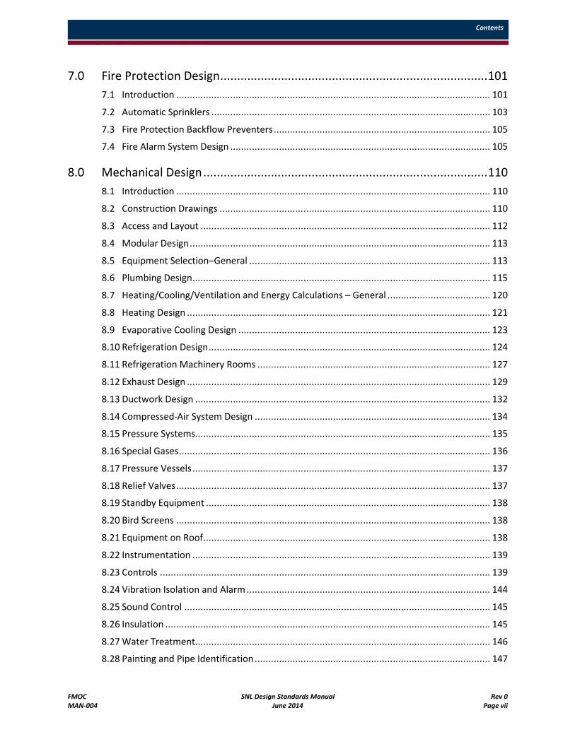
7.0 Fire Protection Design...............................................................................101
7.1 Introduction .................................................................................................................... 101
7.2 Automatic Sprinklers ....................................................................................................... 103
7.3 Fire Protection Backflow Preventers................................................................................ 105
7.4 Fire Alarm System Design ................................................................................................ 105
8.0 Mechanical Design....................................................................................110
8.1 Introduction .................................................................................................................... 110
8.2 Construction Drawings .................................................................................................... 110
8.3 Access and Layout ........................................................................................................... 112
8.4 Modular Design............................................................................................................... 113
8.5 Equipment Selection–General ......................................................................................... 113
8.6 Plumbing Design.............................................................................................................. 115
8.7 Heating/Cooling/Ventilation and Energy Calculations – General ...................................... 120
8.8 Heating Design ................................................................................................................ 121
8.9 Evaporative Cooling Design ............................................................................................. 123
8.10 Refrigeration Design........................................................................................................ 124
8.11 Refrigeration Machinery Rooms ...................................................................................... 127
8.12 Exhaust Design ................................................................................................................ 129
8.13 Ductwork Design ............................................................................................................. 132
8.14 Compressed-Air System Design ....................................................................................... 134
8.15 Pressure Systems............................................................................................................. 135
8.16 Special Gases................................................................................................................... 136
8.17 Pressure Vessels.............................................................................................................. 137
8.18 Relief Valves.................................................................................................................... 137
8.19 Standby Equipment ......................................................................................................... 138
8.20 Bird Screens .................................................................................................................... 138
8.21 Equipment on Roof.......................................................................................................... 138
8.22 Instrumentation .............................................................................................................. 139
8.23 Controls .......................................................................................................................... 139
8.24 Vibration Isolation and Alarm .......................................................................................... 144
8.25 Sound Control ................................................................................................................. 145
8.26 Insulation ........................................................................................................................ 145
8.27 Water Treatment............................................................................................................. 146
8.28 Painting and Pipe Identification ....................................................................................... 147
Contents
FMOC SNL Design Standards Manual Rev 0MAN-004 June 2014 Page viii
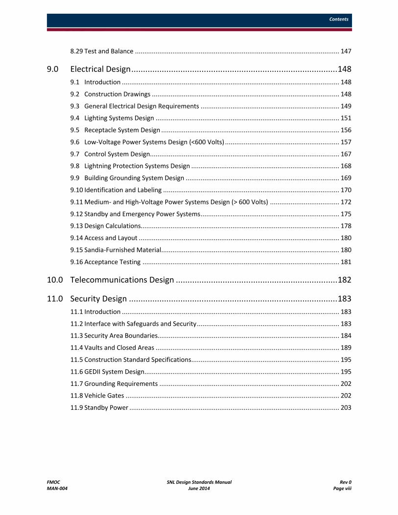
8.29 Test and Balance ............................................................................................................. 147
9.0 Electrical Design........................................................................................148
9.1 Introduction .................................................................................................................... 148
9.2 Construction Drawings .................................................................................................... 148
9.3 General Electrical Design Requirements .......................................................................... 149
9.4 Lighting Systems Design .................................................................................................. 151
9.5 Receptacle System Design ............................................................................................... 156
9.6 Low-Voltage Power Systems Design (<600 Volts) ............................................................. 157
9.7 Control System Design..................................................................................................... 167
9.8 Lightning Protection Systems Design ............................................................................... 168
9.9 Building Grounding System Design .................................................................................. 169
9.10 Identification and Labeling .............................................................................................. 170
9.11 Medium- and High-Voltage Power Systems Design (> 600 Volts) ..................................... 172
9.12 Standby and Emergency Power Systems.......................................................................... 175
9.13 Design Calculations.......................................................................................................... 178
9.14 Access and Layout ........................................................................................................... 180
9.15 Sandia-Furnished Material............................................................................................... 180
9.16 Acceptance Testing ......................................................................................................... 181
10.0 Telecommunications Design .....................................................................182
11.0 Security Design .........................................................................................183
11.1 Introduction .................................................................................................................... 183
11.2 Interface with Safeguards and Security............................................................................ 183
11.3 Security Area Boundaries................................................................................................. 184
11.4 Vaults and Closed Areas .................................................................................................. 189
11.5 Construction Standard Specifications............................................................................... 195
11.6 GEDII System Design........................................................................................................ 195
11.7 Grounding Requirements ................................................................................................ 202
11.8 Vehicle Gates .................................................................................................................. 202
11.9 Standby Power ................................................................................................................ 203
Contents
FMOC SNL Design Standards Manual Rev 0MAN-004 June 2014 Page ix
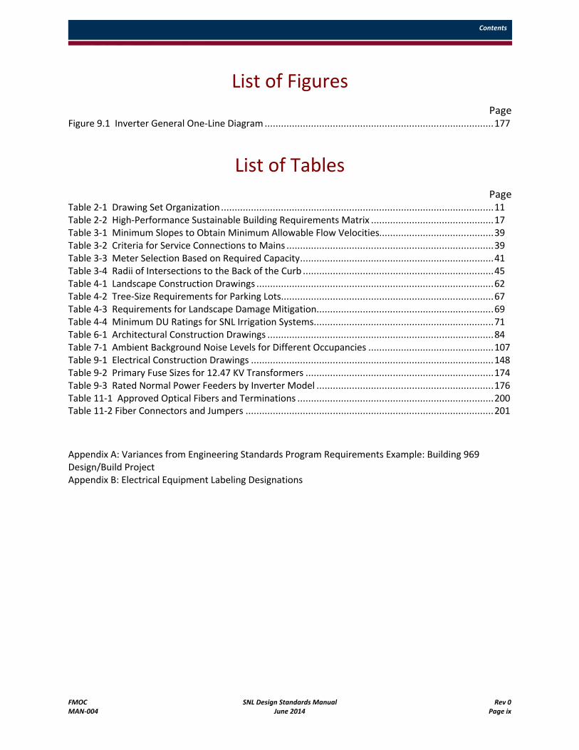
List of Figures
PageFigure 9.1 Inverter General One-Line Diagram ....................................................................................177
List of TablesPage
Table 2-1 Drawing Set Organization....................................................................................................11Table 2-2 High-Performance Sustainable Building Requirements Matrix .............................................17Table 3-1 Minimum Slopes to Obtain Minimum Allowable Flow Velocities..........................................39Table 3-2 Criteria for Service Connections to Mains ............................................................................39Table 3-3 Meter Selection Based on Required Capacity.......................................................................41Table 3-4 Radii of Intersections to the Back of the Curb ......................................................................45Table 4-1 Landscape Construction Drawings .......................................................................................62Table 4-2 Tree-Size Requirements for Parking Lots..............................................................................67Table 4-3 Requirements for Landscape Damage Mitigation.................................................................69Table 4-4 Minimum DU Ratings for SNL Irrigation Systems..................................................................71Table 6-1 Architectural Construction Drawings ...................................................................................84Table 7-1 Ambient Background Noise Levels for Different Occupancies ..............................................107Table 9-1 Electrical Construction Drawings .........................................................................................148Table 9-2 Primary Fuse Sizes for 12.47 KV Transformers .....................................................................174Table 9-3 Rated Normal Power Feeders by Inverter Model .................................................................176Table 11-1 Approved Optical Fibers and Terminations ........................................................................200Table 11-2 Fiber Connectors and Jumpers ...........................................................................................201
Appendix A: Variances from Engineering Standards Program Requirements Example: Building 969 Design/Build ProjectAppendix B: Electrical Equipment Labeling Designations
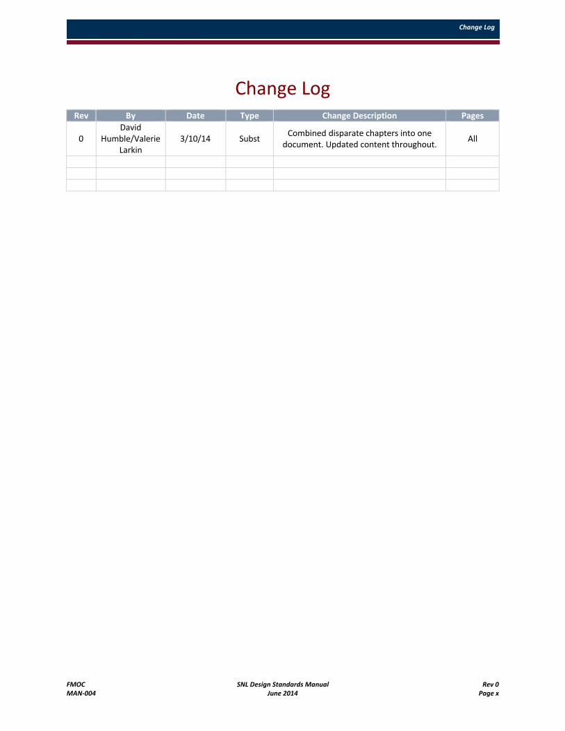
Change Log
FMOC SNL Design Standards Manual Rev 0MAN-004 June 2014 Page x
Change LogRev By Date Type Change Description Pages
0David
Humble/Valerie Larkin
3/10/14 SubstCombined disparate chapters into one
document. Updated content throughout.All
Acronyms
FMOC SNL Design Standards Manual Rev 0MAN-004 June 2014 Page xi
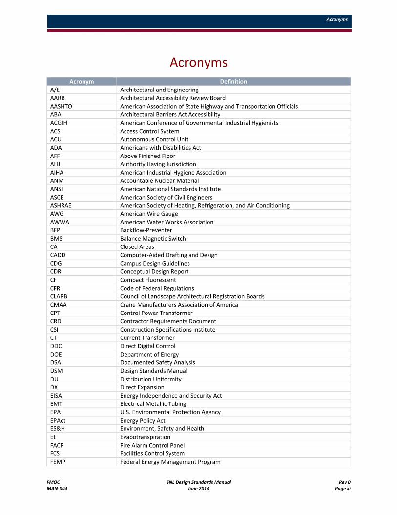
AcronymsAcronym Definition
A/E Architectural and Engineering
AARB Architectural Accessibility Review Board
AASHTO American Association of State Highway and Transportation Officials
ABA Architectural Barriers Act Accessibility
ACGIH American Conference of Governmental Industrial Hygienists
ACS Access Control System
ACU Autonomous Control Unit
ADA Americans with Disabilities Act
AFF Above Finished Floor
AHJ Authority Having Jurisdiction
AIHA American Industrial Hygiene Association
ANM Accountable Nuclear Material
ANSI American National Standards Institute
ASCE American Society of Civil Engineers
ASHRAE American Society of Heating, Refrigeration, and Air Conditioning AWG American Wire Gauge
AWWA American Water Works Association
BFP Backflow-Preventer
BMS Balance Magnetic Switch
CA Closed Areas
CADD Computer-Aided Drafting and Design
CDG Campus Design Guidelines
CDR Conceptual Design Report
CF Compact Fluorescent
CFR Code of Federal Regulations
CLARB Council of Landscape Architectural Registration Boards
CMAA Crane Manufacturers Association of America
CPT Control Power Transformer
CRD Contractor Requirements Document
CSI Construction Specifications Institute
CT Current Transformer
DDC Direct Digital Control
DOE Department of Energy DSA Documented Safety Analysis
DSM Design Standards Manual
DU Distribution Uniformity
DX Direct Expansion
EISA Energy Independence and Security Act
EMT Electrical Metallic Tubing
EPA U.S. Environmental Protection Agency
EPAct Energy Policy Act
ES&H Environment, Safety and Health
Et Evapotranspiration
FACP Fire Alarm Control Panel
FCS Facilities Control System
FEMP Federal Energy Management Program
Acronyms
FMOC SNL Design Standards Manual Rev 0MAN-004 June 2014 Page xii
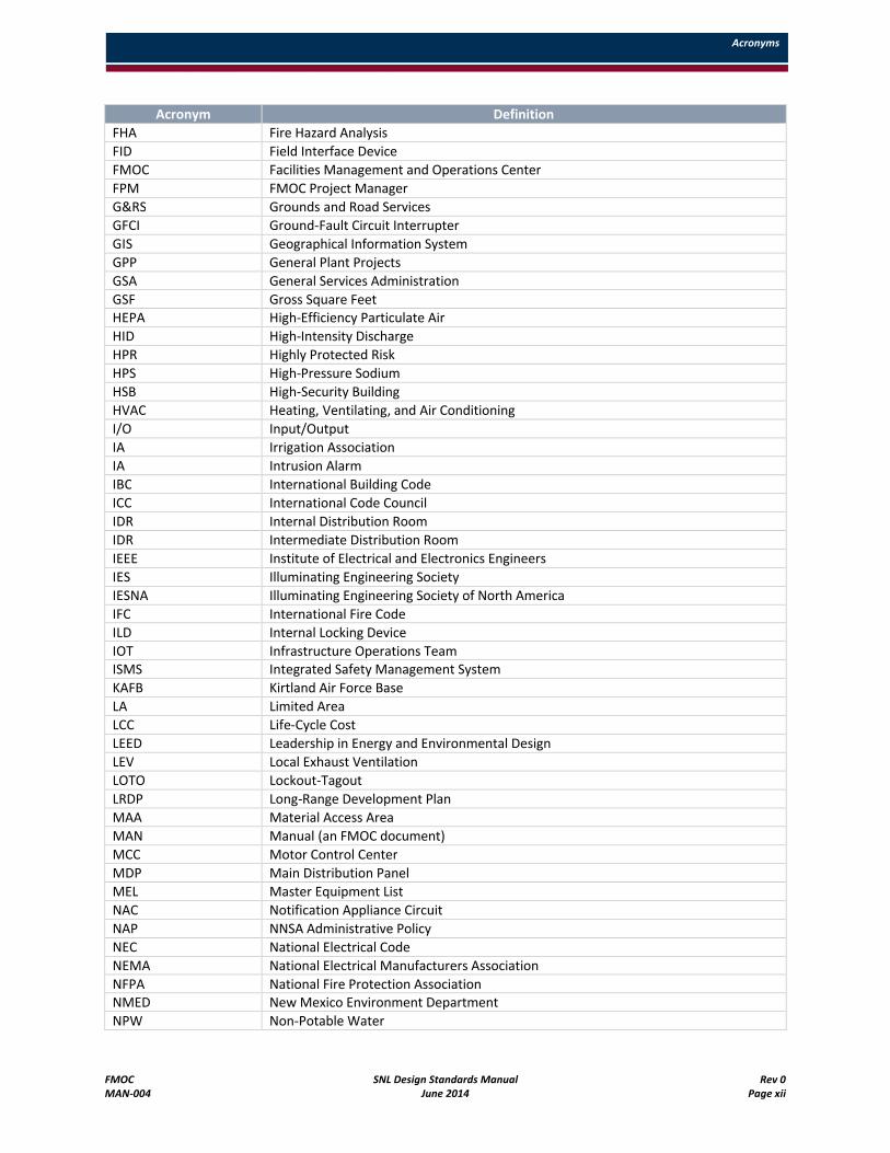
Acronym Definition
FHA Fire Hazard Analysis
FID Field Interface Device
FMOC Facilities Management and Operations Center
FPM FMOC Project Manager
G&RS Grounds and Road Services
GFCI Ground-Fault Circuit Interrupter
GIS Geographical Information System
GPP General Plant Projects
GSA General Services Administration
GSF Gross Square Feet HEPA High-Efficiency Particulate Air
HID High-Intensity Discharge
HPR Highly Protected Risk
HPS High-Pressure Sodium
HSB High-Security Building
HVAC Heating, Ventilating, and Air Conditioning
I/O Input/Output
IA Irrigation Association
IA Intrusion Alarm
IBC International Building Code
ICC International Code Council
IDR Internal Distribution Room
IDR Intermediate Distribution Room
IEEE Institute of Electrical and Electronics Engineers
IES Illuminating Engineering Society
IESNA Illuminating Engineering Society of North America
IFC International Fire Code
ILD Internal Locking Device
IOT Infrastructure Operations Team ISMS Integrated Safety Management System
KAFB Kirtland Air Force Base
LA Limited Area
LCC Life-Cycle Cost
LEED Leadership in Energy and Environmental Design
LEV Local Exhaust Ventilation
LOTO Lockout-Tagout
LRDP Long-Range Development Plan
MAA Material Access Area
MAN Manual (an FMOC document)
MCC Motor Control Center
MDP Main Distribution Panel
MEL Master Equipment List
NAC Notification Appliance Circuit
NAP NNSA Administrative Policy
NEC National Electrical Code
NEMA National Electrical Manufacturers Association
NFPA National Fire Protection Association NMED New Mexico Environment Department
NPW Non-Potable Water
Acronyms
FMOC SNL Design Standards Manual Rev 0MAN-004 June 2014 Page xiii
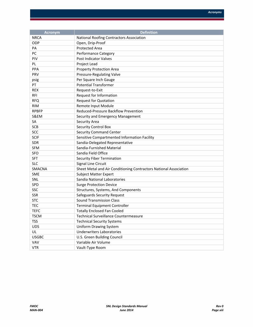
Acronym Definition
NRCA National Roofing Contractors Association
ODP Open, Drip-Proof
PA Protected Area
PC Performance Category
PIV Post Indicator Valves
PL Project Lead
PPA Property Protection Area
PRV Pressure-Regulating Valve
psig Per Square Inch Gauge
PT Potential Transformer REX Request-to-Exit
RFI Request for Information
RFQ Request for Quotation
RIM Remote Input Module
RPBFP Reduced-Pressure Backflow Prevention
S&EM Security and Emergency Management
SA Security Area
SCB Security Control Box
SCC Security Command Center
SCIF Sensitive Compartmented Information Facility
SDR Sandia-Delegated Representative
SFM Sandia-Furnished Material
SFO Sandia Field Office
SFT Security Fiber Termination
SLC Signal Line Circuit
SMACNA Sheet Metal and Air Conditioning Contractors National Association
SME Subject Matter Expert
SNL Sandia National Laboratories
SPD Surge Protection Device SSC Structures, Systems, And Components
SSR Safeguards Security Request
STC Sound Transmission Class
TEC Terminal Equipment Controller
TEFC Totally Enclosed Fan Cooled
TSCM Technical Surveillance Countermeasure
TSS Technical Security Systems
UDS Uniform Drawing System
UL Underwriters Laboratories
USGBC U.S. Green Building Council
VAV Variable Air Volume
VTR Vault-Type Room

Acronyms
FMOC SNL Design Standards Manual Rev 0MAN-004 June 2014 Page xiv
1.0 Introduction
FMOC SNL Design Standards Manual Rev 0MAN-004 June 2014 Page 1
1.0 Introduction
1.1 Document Purpose
At Sandia National Laboratories in New Mexico (SNL/NM), the design, construction, operation, and maintenance of facilities is guided by industry standards, a graded approach, and the systematic analysis of life cycle benefits received for costs incurred. The design of the physical plant must ensure that the facilities are "fit for use," and provide conditions that effectively, efficiently, and safely support current and future mission needs. In addition, SNL/NM applies sustainable design principles, using an integrated whole-building design approach, from site planning to facility design, construction, and operation to ensure building resource efficiency and the health and productivity of occupants. The safety and health of the workforce and the public, any possible effects on the environment, and compliance with building codes take precedence over project issues, such as performance, cost, and schedule.
These design standards generally apply to all disciplines on all SNL/NM projects. Architectural and engineering design must be both functional and cost-effective. Facility design must be tailored to fit its intended function, while emphasizing low-maintenance, energy-efficient, and energy-conscious design. Design facilities that can be maintained easily, with readily accessible equipment areas, low maintenance, and quality systems. To promote an orderly and efficient appearance, architectural features of new facilities must complement and enhance the existing architecture at the site. As an Architectural and Engineering (A/E) professional, you must advise the Project Manager when this approach is prohibitively expensive.
You are encouraged to use professional judgment and ingenuity to produce a coordinated interdisciplinary design that is cost-effective, easily contractible or buildable, high-performing, aesthetically pleasing, and compliant with applicable building codes. Close coordination and development of civil, landscape, structural, architectural, fire protection, mechanical, electrical, telecommunications, and security features is expected to ensure compatibility with planned functional equipment and to facilitate constructability. If portions of the design are subcontracted to specialists, delivery of the finished design documents must not be considered complete until the subcontracted portions are also submitted for review.
You must, along with support consultants, perform functional analyses and programming in developing design solutions. These solutions must reflect coordination of the competing functional, budgetary, and physical requirements for the project. During design phases, meetings between you and the SNL/NM Project Team to discuss and resolve design issues are required. These meetings are a normal part of the design process. For specific design-review requirements, see the project-specific Design Criteria.
In addition to the design requirements described in this manual, instructive information is provided to explain the sustainable building practice goals for design, construction, operation, and maintenance of SNL/NM facilities. Please notify SNL/NM personnel of design best practices not included in this manual,so they can be incorporated in future updates.
You must convey all documents describing work to the SNL/NM Project Manager in both hard copy and in an electronic format compatible with the SNL/NM-prescribed CADD and other software packages, and in accordance with a SNL/NM approved standard format. Print all hard copy versions of submitted documents (excluding drawings and renderings) double-sided when practical.

1.0 Introduction
FMOC SNL Design Standards Manual Rev 0MAN-004 June 2014 Page 2
1.2 Audience
The Facilities Management and Operations Center (FMOC) has written this Design Standards Manual for design professionals who perform work for SNL/NM. The contents of this manual represent institutional knowledge derived from FMOC design, construction management, operations, and maintenance. To be more efficient and effective in managing SNL/NM's extensive construction and drawing files, refer to this manual first for design work. The manual is directed to you as a competent design professional and is not intended to be a detailed design handbook.
The manual contains general requirements that apply to nonnuclear and nonexplosive facilities. For design and construction requirements for modifications to nuclear or explosive facilities, see the project-specific design requirements noted in the Design Criteria.
The criteria and standards presented in the manual are those determined to be the minimum acceptable values necessary to result in system designs having satisfactory functional characteristics, durability, and operational suitability. You must strive for the best design to suit the circumstances involved, and the designs must reflect sound professional judgment at all times. In addition, you must coordinate design efforts with other project discipline design team members for an integrated site design approach.
1.3 References
Unless otherwise noted, comply with the latest editions of the following references. The latest versions of FMOC construction specifications and standard drawings can be found on the FMOC Contractor Bid Documents and SNL Standard Specifications External Collaborative Network.
1.3.1 Department of Energy Directives
Follow these Department of Energy (DOE) guides, manuals, orders, and standards:
DOE Guide 430.1-1, Cost Estimating Guide
DOE Manual 473.1-1, Physical Protection Program Manual
DOE Order 413.3, Program and Project Management for the Acquisition of Capital Assets
DOE Order 414.1A, Quality Assurance
DOE Order 420.1B, Facility Safety and the Contractor Requirements Document
DOE Order 430.2B, Departmental Energy Renewable Energy, and Transportation Management
DOE Standard 1020-2002, Natural Phenomena Hazards Design and Evaluation Criteria for Department of Energy Facilities
DOE Standard 1021-93, Chg 1, Natural Phenomena Hazards Performance Categorization Guidelines for Structures, Systems, and Components
DOE Standard 1090-2004, Hoisting and Rigging
1.3.2 Code of Federal Regulations
Follow these titles, chapters, and lower-level designations in the Code of Federal Regulations (CFRs):
10 CFR 436, Subpart A, Methodology and Procedures for Life Cycle Cost Analysis
10 CFR 830, Nuclear Safety Management
1.0 Introduction
FMOC SNL Design Standards Manual Rev 0MAN-004 June 2014 Page 3
10 CFR 835 Subpart K, Occupational Radiation Protection Design and Control
10 CFR 851, Worker Safety and Health Program
29 CFR 1910, Occupational Safety and Health Standards
29 CFR 1926, Safety and Health Regulations for Construction
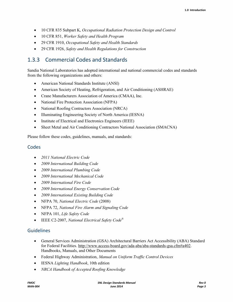
1.3.3 Commercial Codes and Standards
Sandia National Laboratories has adopted international and national commercial codes and standards from the following organizations and others:
American National Standards Institute (ANSI)
American Society of Heating, Refrigeration, and Air Conditioning (ASHRAE)
Crane Manufacturers Association of America (CMAA), Inc.
National Fire Protection Association (NFPA)
National Roofing Contractors Association (NRCA)
Illuminating Engineering Society of North America (IESNA)
Institute of Electrical and Electronics Engineers (IEEE)
Sheet Metal and Air Conditioning Contractors National Association (SMACNA)
Please follow these codes, guidelines, manuals, and standards:
Codes
2011 National Electric Code
2009 International Building Code
2009 International Plumbing Code
2009 International Mechanical Code
2009 International Fire Code
2009 International Energy Conservation Code
2009 International Existing Building Code
NFPA 70, National Electric Code (2008)
NFPA 72, National Fire Alarm and Signaling Code
NFPA 101, Life Safety Code
IEEE C2-2007, National Electrical Safety Code®
Guidelines
General Services Administration (GSA) Architectural Barriers Act Accessibility (ABA) Standard for Federal Facilities. http://www.access-board.gov/ada-aba/aba-standards-gsa.cfm#a402. Handbooks, Manuals, and Other Documents
Federal Highway Administration, Manual on Uniform Traffic Control Devices
IESNA Lighting Handbook, 10th edition
NRCA Handbook of Accepted Roofing Knowledge
1.0 Introduction
FMOC SNL Design Standards Manual Rev 0MAN-004 June 2014 Page 4
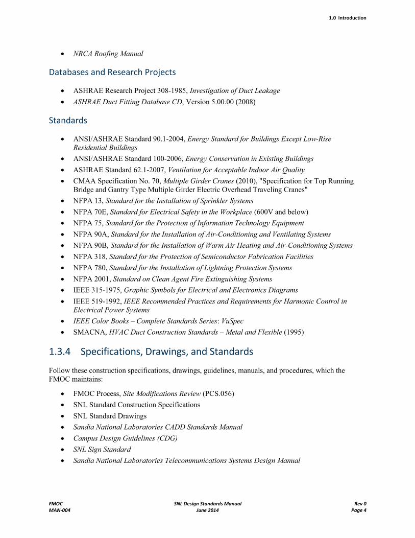
NRCA Roofing Manual
Databases and Research Projects
ASHRAE Research Project 308-1985, Investigation of Duct Leakage
ASHRAE Duct Fitting Database CD, Version 5.00.00 (2008)
Standards
ANSI/ASHRAE Standard 90.1-2004, Energy Standard for Buildings Except Low-Rise Residential Buildings
ANSI/ASHRAE Standard 100-2006, Energy Conservation in Existing Buildings
ASHRAE Standard 62.1-2007, Ventilation for Acceptable Indoor Air Quality
CMAA Specification No. 70, Multiple Girder Cranes (2010), "Specification for Top Running Bridge and Gantry Type Multiple Girder Electric Overhead Traveling Cranes"
NFPA 13, Standard for the Installation of Sprinkler Systems
NFPA 70E, Standard for Electrical Safety in the Workplace (600V and below)
NFPA 75, Standard for the Protection of Information Technology Equipment
NFPA 90A, Standard for the Installation of Air-Conditioning and Ventilating Systems
NFPA 90B, Standard for the Installation of Warm Air Heating and Air-Conditioning Systems
NFPA 318, Standard for the Protection of Semiconductor Fabrication Facilities
NFPA 780, Standard for the Installation of Lightning Protection Systems
NFPA 2001, Standard on Clean Agent Fire Extinguishing Systems
IEEE 315-1975, Graphic Symbols for Electrical and Electronics Diagrams
IEEE 519-1992, IEEE Recommended Practices and Requirements for Harmonic Control in Electrical Power Systems
IEEE Color Books – Complete Standards Series: VuSpec
SMACNA, HVAC Duct Construction Standards – Metal and Flexible (1995)
1.3.4 Specifications, Drawings, and Standards
Follow these construction specifications, drawings, guidelines, manuals, and procedures, which the FMOC maintains:
FMOC Process, Site Modifications Review (PCS.056)
SNL Standard Construction Specifications
SNL Standard Drawings
Sandia National Laboratories CADD Standards Manual
Campus Design Guidelines (CDG)
SNL Sign Standard
Sandia National Laboratories Telecommunications Systems Design Manual
1.0 Introduction
FMOC SNL Design Standards Manual Rev 0MAN-004 June 2014 Page 5
1.4 Updates to This Manual
As the industry standards and practices cited in this manual change, the FMOC will issue updates. The FMOC intends to revise the manual when changes are warranted. Consult the external SNL website for the current version.
2.0 General Design Standards and Procedures
FMOC SNL Design Standards Manual Rev 0MAN-004 June 2014 Page 6
2.0 General Design Standards and Procedures
2.1 Introduction
As a design professional or Architect/Engineer (A/E) doing work for Sandia National Laboratories (SNL), you are responsible for the final design of a project, according to the requirements in this Design Standards Manual, project-specific design criteria (when included), and additional contract documents. It is also your responsibility to provide a facility design that meets the required functions in the most cost-effective manner to satisfy current mission needs of SNL and provide flexibility, as requested, in meetingfuture mission needs.
You are responsible for compliance with State of New Mexico requirements for licensure as regulated by the New Mexico Board of Examiners for Architects, the New Mexico Board of Landscape Architects, and the New Mexico State Board of Licensure for Professional Engineers and Surveyors.
In accordance with the laws of the State of New Mexico, your design must comply with the 2009 International Building Code (IBC). The deliverable design package, including drawings, specifications, code footprint/analyses, and calculations must bear the seal, signature, and date of signature from the NewMexico licensed design professional responsible and in charge of design. Multidiscipline projects require multiple seals, signatures, and dates of signatures. Alterations to the design package (including the post-construction red-lines) that materially change the original design intent, and result in the production of new or changed documents, must be resealed. Amended construction documents must be maintained in accordance with IBC Chapter 1 provisions.
You are also responsible for following SNL standard specifications and standard drawings and verifying that the drawings match these standards.
2.2 Design Process
The Sandia National Laboratories New Mexico (SNL/NM) site uses an integrated whole building design approach on all new construction and major renovation projects. This design approach considers the interrelationships among building siting, design elements, energy and resource constraints, building systems, and building function, before predesign activities are initiated. To identify the effects these factors have on one another requires a multidisciplinary design and construction team consisting of Site Planners, Landscape Architects, Architects, Engineers, Contractors, Interior Designers, Lighting Designers, Building Owners, Occupants, Maintenance Personnel, and any other relevant stakeholders. Such a multidisciplinary team must be assembled prior to initiating design activities to ensure the coordination of individual design efforts and sharing of specialized expertise to achieve an integratedwhole-building design process.
This internal integrated SNL/NM project team generally consists of a SNL/NM Project Lead (PL) and primary discipline leads (civil, landscape, architect, structural, mechanical, electrical, controls, fire protection, security, telecommunications, building operations , and safety) assigned to each project.
You are responsible for determining all requirements necessary to create a comprehensive, functional, buildable, and code-compliant project design. Use resources, such as the Conceptual Design Report(CDR), design criteria, building systems summaries (available for major facilities from the Systems Engineer), this Design Standards Manual, and additional information gathered through the Title I "programming" exercise to determine solutions to design questions. During the initial phase of a project,
2.0 General Design Standards and Procedures
FMOC SNL Design Standards Manual Rev 0MAN-004 June 2014 Page 7
the CDR and design criteria are developed from an analysis of project requirements to establish functional and performance specifications and architectural design attributes. The development of the CDR and design criteria must align with the standards and methods of this Design Standards Manual. To ensure this alignment, initial design phase activities must also include the participation of the SNL/NM project team, as well as the facility owner, occupant, and maintenance representatives.
A working relationship is developed early in the design process between the A/E team and the SNL/NM project team to expedite the transfer of additional required information. You may be required to go directly to additional SNL/NM stakeholders to obtain additional design direction if the project team counterpart is not available. All correspondence and stakeholder interactions of this type must be documented and copied to the applicable SNL/NM project team members. The SNL/NM Project Leadmust provide an expanded list of all project stakeholders to you early in the design process.
2.3 Design Quality
Architectural and engineering design must be code-compliant, functional, and cost-effective. The designermust tailor the facility's design to fit its intended function using sustainable design principles, including but not limited to low maintenance, energy and water efficiency, material and resource conservation, and indoor environmental quality. The designer must design facilities that are easily maintained, with readily accessible equipment areas, low maintenance interior and exterior surfaces, and quality roofing systems. To promote an orderly and efficient appearance, architectural features of new facilities must complement and enhance existing architecture at the site.
Begin with informed assumptions and proceed to identify solutions. As problems gain more definition and as alternative solutions become more refined, use your professional judgment and ingenuity to produce a coordinated interdisciplinary design that is cost-effective, easily contractible, constructible, high-performing in energy efficiency, code-compliant, and aesthetically pleasing. Along with support consultants, perform functional analyses and programming in developing design solutions. These solutions reflect coordination of the competing functional, budgetary, and physical requirements for the project. Prior to and throughout the design process, meetings to establish, discuss, and resolve design issues are required. These meetings are a normal part of the design process and are critical to achieving a fully integrated, whole-building design. For specific design review requirements, see the project-specific design criteria.
Throughout the design process, conduct discipline coordination sessions to resolve conflicts about the use of building space. In the concept-definition phase and up to 30% design completion, mechanical rooms, electrical rooms, utility chases both intra-floor and inter-floor, and outdoor equipment, such as substations and cooling towers, are shown on the drawings. As equipment items are chosen up to 60% design completion, the drawings are refined to include feeder conduit and liquid piping runs, major ductwork runs, equipment locations on the utility room floor plans and outside, and general assignment of interstitial spaces above ceilings and in chases. At 90% design completion and with delivery of the final contractual design package, all discipline conflicts must be resolved, to include but not be limited to, the following:
Compliance of all design documents with applicable building codes
National Electrical Code (NEC) clearances and exit paths for electrical panel boards, switchgear, and drives
Access to air handlers and other HVAC equipment, including space to service filters, fan belts, motors, and bearings, and remove heat exchanger components
2.0 General Design Standards and Procedures
FMOC SNL Design Standards Manual Rev 0MAN-004 June 2014 Page 8
Clear space to open all access doors and panels fully, with the understanding that doors of one equipment item may swing into the clearance space of another when the second item does not require simultaneous access
Design of service lights, catwalks, and convenience receptacles in larger interstitial spaces where the room lighting and receptacles may be inadequate
Three-dimensional space assignment of the disciplines in interstitial spaces and chases
Structure-mounted pick points and dolly space for removal and replacement of major items, such as a large motor
Location of lighting fixtures so they are not blocked by other equipment and that they cast light into spaces that can be occupied and not, for instance, on top of a fume hood. This includes arrangement of fixtures in a lay-in ceiling to accommodate modular furniture and not just in a symmetrical pattern for an empty room.
Location of variable air volume (VAV) boxes such that they can be serviced easily
Location of electrical junction boxes for lighting, communications, alarms and access control, and other systems that could reasonably be expected to require periodic access during the life of the building, such that access to each item does not require dismantlement or outages of items not related to that discipline
Minimizing the location of major items within a closed area (formerly referred to as a vault-type room or VTR), such that they are not readily accessible for servicing, even when dedicated to that closed area
Location of outside equipment such that adjacent space use is compatible; for instance, not locating an air intake near a vehicle area, and not locating fire sprinkler and roof drains near pedestrian paths
Partitioning of building utility space separate from (but may be adjacent to) programmatic utility runs
Full design (route and spacing) of conduit and piping runs of 2 inches and larger, and restricted use of home-run designators to smaller terminal runs and branch circuits
Access means or choice of equipment items that afford ready servicing in lobbies, open stairwells, and other areas where ceiling height is multistory
Portions of a facility design that are subcontracted, such as site preparation, asbestos remediation, fire protection sprinkler design, and similar specialties, must be contracted for and delivered such that the contracted portion is incorporated into your deliverable package, so it may be considered by the Engineer or Architect with responsible charge, reviewed by the SNL project team, and integrated so that the subcontracted effort is a part of the whole as if it had not been subcontracted. For example, you must not set aside portions of the design work to be completed later and forward as a short-suspense submittal or shop drawing.
Construction projects at SNL occasionally affect structures, systems, and components (SSCs) that have been designated as Safety-Significant or Safety-Class. Safety SSCs are defined as those SSCs identified in the Documented Safety Analysis (DSA) for the facility as required by Title 10 of the Code of Federal Regulations (CFR) Section 830 (10 CFR 830), and are commonly found in nuclear facilities. New or modified Safety SSCs must be designed to readily facilitate all required functional testing.
2.3.1 Value Engineering
The designer is responsible for performing value engineering to determine the project component alternatives that satisfy the same basic function or set of functions at the optimum project cost. Value
2.0 General Design Standards and Procedures
FMOC SNL Design Standards Manual Rev 0MAN-004 June 2014 Page 9
engineering, which always includes, at a minimum, the SNL/NM project team, project owner, and occupants, follows a result-driven job plan consisting of the following phases:
Selection
Information
Creativity
Analysis
Development
Presentation
Implementation
Verification
Value engineering begins during the programming stage of the design and continues throughout the design process.
2.3.2 Life-Cycle Analysis
The Federal Energy Management Program (FEMP) established 10 CFR 436 to promote life cycle cost-effective investments in energy systems, water systems, and energy and water conservation measures for federal buildings. This life-cycle cost (LCC) methodology is a systematic analysis of relevant costs, excluding sunk costs, over a study period, relating initial costs to future costs by discounting future costs to current values.
Perform LCC analyses in the early phases of line-item projects and major projects to support value engineering and sustainable design. Life-cycle costing makes economic comparisons between systems similar in function and enables selection of the lowest LCC system.
Combining value engineering and life-cycle costing can potentially identify the best value alternative by comparing the first cost and life-cycle costs of each alternative. In this manner value engineering and life-cycle costing are both used during early project phases to develop an "equal playing field" for determining tradeoffs and making decisions to balance, among other criteria, environmental performance with total cost, reliability, safety, and functionality. This equal comparison enables sustainable development technologies and integration to be fully evaluated for overall performance.
An integrated project team approach is critical to achieving an integrated whole building design. Value engineering and LCC professionals should be included in the design team in the earliest-possible project phases. The framework for integrating value engineering and LCC into the design process is as follows:
Perform a requirements assessment to establish the parameters for sustainable development
Perform conceptual planning using macro-level value engineering and life-cycle costing (including energy modeling)
Conduct programming and budgeting activities
Perform design using complete value engineering and life-cycle costing evaluations
2.0 General Design Standards and Procedures
FMOC SNL Design Standards Manual Rev 0MAN-004 June 2014 Page 10
2.4 General Requirements for Construction Drawing Files
2.4.1 CADD Standards Manual
Facilities drawing files for SNL/NM must be created or modified to comply with the CADD Standards Manual. This manual contains specific information and files related to CADD requirements, standards, and processes. Exceptions to compliance requirements may be made as necessary to benefit the project, if approved by the SNL/NM Sandia-Delegated Representative (SDR), who is usually the Project Lead. No exceptions are allowed for final as-built files.
2.4.2 Locating Drawing Files
Because facilities at SNL/NM are continually being modified or extended, Facilities Engineering uses an active record drawing file system to represent those changes. Identification of the most up-to-date record drawing files that are affected by a particular project is part of the project design requirements. Half-scale hard copies and current, online, read-only access to numerous drawing files are available in the Facilities Engineering Library.
2.4.3 Requesting Drawing Files from the Drawing File System
The Facilities Management and Operations Center (FMOC) operates a closed drawing file system. Only authorized personnel with a valid user name and password may check out record drawing files. Off-site contractors are assigned an on-site CADD Technician as a point-of-contact for all files being checked in and out of the Facilities Document Management System.
2.4.4 Using Record Drawing Files
Modifications to existing facilities must be made by revising the record drawing files, unless otherwise directed. New drawings must be prepared if the existing record drawings are too crowded or obsolete. All plans, elevations, sections, details, and diagrams must be completed to sufficient size and detail to clearly and completely define the project for bidding and construction purposes.
Because the hard-copy drawings may be outdated, information used to interface or develop the design must be field verified.
2.4.5 Drawing Numbering System
Distinguishable types of project drawing plot files that are commonly (or are specified to be) created on separate drawing files must be numbered in a modified "Uniform Drawing System" numbering scheme as described in the CADD Standards Manual.
2.4.6 Standard Drawings
Standard drawings are used to facilitate the design process by providing typical details and templates for incorporation into design packages. Although all of the drawings are called standard drawings, there are actually three categories of standard drawings:
2.0 General Design Standards and Procedures
FMOC SNL Design Standards Manual Rev 0MAN-004 June 2014 Page 11
Standard Drawings: These drawings are to be used as-is for construction. No modifications to these drawings are required beyond project-specific title block additions.
Template Standard Drawings: These drawings are to be used as a starting point to create a new building or utility drawing that are be assigned its own unique number and filed as such.
Design Standard Drawings: These drawings are to be used for design calculations and conceptual design layout. These drawings are not be included in a construction set except for design-build projects.
Hard copies of standard drawings are located in the FMOC Engineering Library in 11" by 17" blue binders labeled "Active Standard Drawings." These drawings are not to be removed from the Library, though copies of the drawings may be made. All standard drawings are CADD vector files and are also available in Adobe Acrobat (.pdf) format. All A/Es on SNL/NM's distribution list should have electronic copies of the standard drawings. If electronic copies are required but not available in your system, request them from the SNL/NM Project Lead.
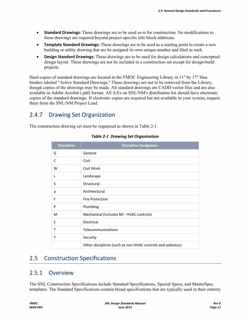
2.4.7 Drawing Set Organization
The construction drawing set must be organized as shown in Table 2-1.
Table 2-1 Drawing Set Organization
Discipline Discipline Designator
G General
C Civil
W Civil Work
L Landscape
S Structural
a Architectural
F Fire Protection
P Plumbing
M Mechanical (includes Mi - HVAC controls)
E Electrical
T Telecommunications
T Security
Other disciplines (such as non-HVAC controls and asbestos)
2.5 Construction Specifications
2.5.1 Overview
The SNL Construction Specifications include Standard Specifications, Special Specs, and MasterSpec templates. The Standard Specifications contain broad specifications that are typically used in their entirety
2.0 General Design Standards and Procedures
FMOC SNL Design Standards Manual Rev 0MAN-004 June 2014 Page 12
without modification. Project specific specifications are referred to as Special Specifications. The Master Specification templates are available to be edited to reflect project-specific applications.
2.5.2 Standard Specifications
Standard Specifications have been developed by SNL Architects and Engineers to establish a consistent building system throughout the SNL campus with a certain level of quality, energy efficiency, safety, security, and maintainability. You must become familiar with the specifications verify that they are applicable to their project or if modifications are required. If it is determined that a Standard Specification needs modifications for a specific project, you must consult with the SNL project team to discuss the extent of the changes.
Continuous improvement is a goal of the Standards Program and the design community is encouraged to submit ideas for improvement.
2.5.3 Special Specs
Special Specs are specifications developed for a particular project and only apply to that project. Special Specs are either a new specification or a modified Standard Specification. Special Specs must be written in accordance with the Construction Specifications Practice Guide published by the Construction Specifications Institute (CSI).
Special Specs may be considered as Standard Specification if submitted to the Standards Program as an improvement idea.
2.5.4 MasterSpec Templates
Master Specification Templates from MasterSpec (1994 and 2004 format) are available from the Standards Program that may be used to develop a new specification to be considered as a standard or as project-specific.
2.6 Miscellaneous Design Issues
2.6.1 Sandia-Furnished Material
You must identify all Sandia-Furnished Material (SFM) in the specifications and the construction contract and verify that the existing equipment is functional for the intended use in the design.
2.6.2 Installation of Customer Equipment
When installing equipment owned by the end-user customer, You must document all installation issues with the equipment, including size, weight, electrical, data communications, chilled water, exhaust, drains, serviceability, safety, and so on.
2.0 General Design Standards and Procedures
FMOC SNL Design Standards Manual Rev 0MAN-004 June 2014 Page 13
2.6.3 Descriptive Submittals
Projects submittals must be in accordance with SNL Standard Specification 01330, Submittal Procedures. Design professional must review all specifications to verify that the desired Descriptive Submittals are being requested and must list all necessary submittal requirements to ensure full project compliance.
2.6.4 Master Equipment List Update
When equipment items are removed or added to a building as part of a project, the design professional must provide information to SNL's Maintenance Planning Services to update the Master Equipment List (MEL) as appropriate. You must compare project equipment selections and/or removals during design to the MEL Update Notification form. This is especially important and applicable for equipment replacements, and remodels and renovations involving equipment replacements, as well as new construction projects. Advise the SNL/NM Project Lead (PL) or project team discipline lead, as applicable, of the scope of the project during design and provide the list of as-designed equipment to be provided/removed. The list becomes a part of the design package and is updated during construction, as necessary, by approved submittals or change orders.
2.6.5 Temporary Services
Prepare complete designs for all temporary service connections and installations required for theconstruction contractor's use of government-owned utilities. These designs are subject to requirements noted herein.
2.6.6 Site Access Requirements
Most areas at SNL/NM are subject to security and access regulations. To obtain access to the Project areas, you must submit a letter to the SDR identifying personnel needing access, company name or affiliation, and the anticipated dates and times of visits. Those who have an active U.S. Department of Energy (DOE) L or Q clearance are furnished temporary badges that permit access. All others are provided an escort while in a secure area. All personnel must have a badge, regardless of whether they are in secure areas or not. Contact the SDR at the beginning of the project for more details.
2.6.7 Tobacco-Free Campus Requirement
Sandia National Laboratories sites are completely tobacco-free campuses per corporate procedure HR100.4.10, Maintain a Tobacco-Free Environment; therefore, all facility designs must not include any provisions for smoking areas, smokeless tobacco use, tobacco vending, or similar features.
2.7 Design Information and Calculations
Design drawings for all disciplines must be accompanied by sufficient supporting calculations and system operating conditions to clearly convey assumptions, constraints, and how code requirements have been met. Additionally, design of chemical rooms, service/storage areas/yards, and/or other elements -including hazardous materials and life safety implications - must include relevant reference to codes-driven tables and calculations (and calculation sheets). Information and calculations must be provided with each submittal.
2.0 General Design Standards and Procedures
FMOC SNL Design Standards Manual Rev 0MAN-004 June 2014 Page 14
You must present design information and calculations on 8½-inch by 11-inch sheets with minimum half-inch margins on all sides, logically arranged, indexed, and bound in book form. Type or hand-letter all material, neatly arrange the sheets, and include the sources of all contents. Present the formulas used and clearly state all assumptions made. Present the following information on each sheet:
SNL/NM Project Number
Sheet Number
Subject
Building Number
Date
Include the following as supporting information:
System and subsystem flow diagrams, including operating conditions and parameters
Free-body diagrams
One-line schematic diagrams, including operating conditions and parameters
Utility system calculations, including operating conditions and parameters
SNL/NM-provided information and direction
When using computer-aided design systems to perform design calculations, also include:
The computer program name and version used.
Information on the building model or paradigm used by the software, so that an engineer unfamiliar with the program can understand the functions, limitations, and method of analysis used. The documentation must be sufficiently complete to allow an engineer to verify the method of data input and interpret the output calculation by hand. This requirement can be waived if the software is also in use at SNL/NM.
Identification of the free-body diagrams, one-line power diagrams, marked plans, flow diagrams, and sketches that are part of the design package, so that another Engineer can easily check for accuracy. This can be part of the calculations pages mentioned above.
A copy of the computer output. Retain a complete copy of input data, worksheets, discs, and other quality assurance records with the project file for possible audit purposes.
Spot-reviews or verifications of the computer output for accuracy and reasonableness.
If the building is a Moderate Hazard Facility, a separate Design Basis Document must be provided, describing all elements and systems of the building.
2.8 Energy Conservation and Sustainable Design Requirements
The goal of SNL is to create buildings and infrastructure that promote a healthful, resource-efficient, and productive working environment. To achieve this goal, all new buildings and renovation projects must be designed, constructed, and commissioned for operation using an integrated whole-building design approach and the latest sustainable building technologies. Every reasonable effort must be made to employ life-cycle cost-effective energy and water conservation concepts during design and construction based on the established value engineering concepts that ensure an appropriate balance between project cost, security, maintainability and facilities life-cycle costs.
2.0 General Design Standards and Procedures
FMOC SNL Design Standards Manual Rev 0MAN-004 June 2014 Page 15
Sandia National Laboratories is included in the list of federal agencies required by the Energy Policy Act of 2005 (Public Law 109-58) to incorporate the performance criteria used for ENERGY STAR®-qualified and FEMP-designated products into procurement contracts for energy consuming products and systems. These requirements must be included in all construction specifications and construction, renovation and service contracts.
To demonstrate a commitment to this goal, the following strategies, as confirmed by the responsible SNL/NM Project Lead, must be pursued for all project work at SNL/NM:
Assess opportunities from a whole-building approach to maximize energy and water conservation through comprehensive, integrated evaluations of all components, systems, and, as appropriate, processes.
Use life-cycle cost decision-making balanced with first cost constraints.
Commission equipment and controls in all new construction and renovation projects as an integrated effort during construction, to verify building system performance and functionality for the customers and for Facilities operations and maintenance.
Employ a broad range of advanced energy and water efficiency strategies, including but not limited to central plant optimization, airside supply and exhaust distribution optimization, energy recovery methods, lighting design optimization, and water use reduction measures.
Specify environmentally preferable construction materials and construction waste reduction methods.
Seek recognized certifications that demonstrate this philosophy, such as Leadership in Energy and Environmental Design (LEED), ENERGY STAR, and Green Building awards and certificates.
2.8.1 Sustainable Design, Guiding Principles, and LEED Certification
Sustainable or green-building design minimizes site disturbance, optimizes energy and water use, provides good indoor environmental quality, selects environmentally preferable building products, handles construction and demolition waste in a resource-conserving manner, and improves operations and maintenance.
Two references are commonly recognized as the standard for Sustainable Design and Development of Buildings and Infrastructure. The U.S. Green Building Council (USGBC) has developed the Leadership in Energy and Environmental Design (LEED) Green Building Rating System to evaluate life cycle environmental performance from a whole-building perspective. In addition, an interagency federal task force has developed a set of sustainable design and development principles, comparable to the LEED rating system, known as the Whole Building Design Guide. Both of these programs provide excellent information and should be referenced while conducting facility planning and design work for SNL/NM.Search the Internet for more information about these programs.
You must use sustainable design principles for work conducted at SNL/NM. Architectural and Engineering firms that market sustainable, energy-efficient design as part of their services must assist theFMOC in institutionalizing sustainable design efforts at SNL/NM.
All new buildings and major renovation projects must meet the High-Performance Sustainable Buildings Guidance which includes the Guiding Principles for Sustainable New Construction and Major Renovations (Guiding Principles) and LEED certification requirements. These are separate, but related,activities.
2.0 General Design Standards and Procedures
FMOC SNL Design Standards Manual Rev 0MAN-004 June 2014 Page 16
Submit a Sustainable Design Report during the design process that outlines the sustainable-design approach and demonstrates compliance with the both Guiding Principles and LEED certification requirements.
A Guiding Principles Subject Matter Expert (SME) is available at SNL/NM to assist the Project Lead in documenting compliance. Guiding Principles compliance is internally verified and tracked using the EPA web-based Portfolio Manager system.
In addition, all new buildings and major renovation projects must be certified as "green" buildings through the LEED rating system at the Gold level or higher. All new building and major renovation designs , must be scored using the LEED rating system, in anticipation of submission for certification as a green building. Actual LEED certification requires applicant buildings to satisfy a number of prerequisites and attain a certain number of credits. Once the LEED program prerequisites have been satisfied, applicant buildings are rated based on the number of credits achieved within the rating system. There are four levels of LEED certification: Certified, Silver, Gold, and Platinum (highest).
Sandia National Laboratories in New Mexico provides a LEED Accredited Professional (AP) to register and obtain certification. The certification process first requires registration of the building project with the USGBC to show intent to obtain LEED certification. The USGBC recommends registering early in the project, preferably during the schematic design phase. Following completion of construction activities, an application is submitted to the USGBC LEED Certification Manager. This application includes a narrative of the project, a LEED Scorecard, complete documentation per credit (tabbed) with cover sheets from the Application Template, and a certification fee. The application then goes through an administrative review, a technical review, followed by notification of LEED certification. The USGBC presents the project with a certificate and a metal LEED plaque indicating the certification level. The standard review timeline can take anywhere from eight weeks to several months. As a member of the USGBC in the government-owned, contractor-operated category, SNL/NM building projects are entitled to receive membership benefits and discounts on fee schedules relating to the registration, technical support, and certification process.
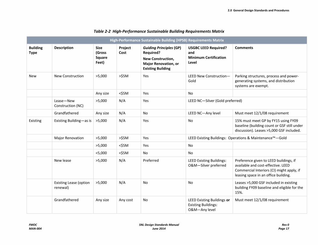
See Table 2-2 for additional requirements based on project type and size.
2.0 General Design Standards and Procedures
FMOC SNL Design Standards Manual Rev 0MAN-004 June 2014 Page 17
Table 2-2 High-Performance Sustainable Building Requirements Matrix
High-Performance Sustainable Building (HPSB) Requirements Matrix
BuildingType
Description Size(Gross Square Feet)
ProjectCost
Guiding Principles (GP) Required?
New Construction, Major Renovation, or Existing Building
USGBC LEED Required?andMinimum Certification Level
Comments
New New Construction >5,000 >$5M Yes LEED New Construction—Gold
Parking structures, process and power-generating systems, and distribution systems are exempt.
Any size <$5M Yes No
Lease—New Construction (NC)
>5,000 N/A Yes LEED NC—Silver (Gold preferred)
Grandfathered Any size N/A No LEED NC—Any level Must meet 12/1/08 requirement
Existing Existing Building—as is >5,000 N/A Yes No 15% must meet GP by FY15 using FY09 baseline (building count or GSF still under discussion). Leases >5,000 GSF included.
Major Renovation >5,000 >$5M Yes LEED Existing Buildings: Operations & Maintenance™—Gold
>5,000 <$5M Yes No
<5,000 <$5M No No
New lease >5,000 N/A Preferred LEED Existing Buildings: O&M—Silver preferred
Preference given to LEED buildings, if available and cost-effective. LEED Commercial Interiors (CI) might apply, if leasing space in an office building.
Existing Lease (option renewal)
>5,000 N/A No No Leases >5,000 GSF included in existing building FY09 baseline and eligible for the 15%.
Grandfathered Any size Any cost No LEED Existing Buildings orExisting Buildings: O&M—Any level
Must meet 12/1/08 requirement
2.0 General Design Standards and Procedures
FMOC SNL Design Standards Manual Rev 0MAN-004 June 2014 Page 18
2.8.2 Building Systems Commissioning
SNL/NM requires that all new construction and major renovation projects include building systems commissioning as a quality control measure. At a minimum, commissioning procedures verify and ensure that fundamental building elements and systems are designed, installed and calibrated to operate as intended. The following fundamental best-practice commissioning procedures must be followed:
Designate a commissioning authority, preferably during preliminary design
Document the operating parameters for each element and system included in the scope of commissioning
Create a commissioning plan that
- Integrates commissioning requirements into the contract documents
- Verifies adequacy of installation, functional performance, training, and manufacturer's documentation
- Documents the results upon completion of commissioning, with an action plan as necessary to ensure correction of any out-of-compliance condition
The Project Lead designates the commissioning team or commissioning authority for the project and ensures that appropriate budget for commissioning has been established, approximately 1.0 to 1.5% of construction cost.
2.8.3 Energy Service Meters
Each distinct building energy service must have a measurement system to accumulate a record or indicator reading of the overall amounts of the electricity and natural gas being delivered. Exception: A building of 5,000 gross square feet (GSF) or less in a complex of buildings may have its measurement system included with another building in the same complex. All required meters must be equipped with provisions to allow for remote reading throughout the SNL/NM Energy Metering System.
2.8.4 Energy Monitoring and Control Systems
All new permanent buildings greater than 5,000 square feet must have a Facilities Control System for interconnection with the SNL/NM Facilities Control System (FCS), unless specifically exempted by the project-specific design criteria, the SNL/NM Project Lead, or both.
2.8.5 Energy Policy Act of 2005 Requirements
According to the Energy Policy Act (EPAct) of 2005, new buildings must be designed to achieve energy-consumption levels approximately 30% below those of the 2004 ASHRAE standard on the International Energy Conservation Code, unless clearly demonstrated not to be LCC-effective. Similar reductions are required for major renovations of existing buildings. The exact energy-consumption goals for a particular building must be negotiated during the Title I and Conceptual Design activities, taking into account the building's mission, model, and programmatic equipment.
2.0 General Design Standards and Procedures
FMOC SNL Design Standards Manual Rev 0MAN-004 June 2014 Page 19
2.9 Conceptual Design (Project Definition) Requirements
If included in your contract, provide conceptual design (project definition) scope and deliverables including the following:
Updated functional and operational requirements documents
Space and equipment data sheets
Updated record drawings for Request for Quotation (RFQ) purposes
Site plans
Floor plans
Building elevations
Building sections
2.10 Title I (Schematic Design) Requirements
Provide Title I Quality Assurance Review deliverables (unless stated otherwise by design criteria) to include the following:
Design analysis (design narrative and calculations)
Drawing prints and files
Preliminary cost estimates
All additional requirements as defined in the project-specific design criteria
These Title I review requirements are described in the following sections.
2.10.1 Design Analysis
Present conceptual design analyses for the entire facility or portions thereof, including appropriate environmental or utility systems when required. The conceptual design analyses for alternate approaches to the job include the following:
Statement of purpose and function
Statement of factors considered and provided for
Economic justification
References of previous studies of record
In general, these analyses present the complete documentation of the facts that are considered when forming conclusions for alternate approaches.
After the analyses have been considered and a choice agreed on in conference with the SDR, complete the chosen conceptual analysis and submit it at Title I. At a minimum, it must contain the pertinent facts involved in the concept, the conclusions reached, along with the reasons for these conclusions, and the alternatives considered.
2.0 General Design Standards and Procedures
FMOC SNL Design Standards Manual Rev 0MAN-004 June 2014 Page 20
2.10.2 Drawings
The design criteria identify the specific requirements for determining percentage complete for each discipline prior to starting design. If not indicated, the Title I final submittal is approximately 30%complete for the entire project.
Civil
Complete drawing list, for example:
- Grading, drainage, and paving concept plan
- Utility location and connection point plan, including the following: Water (domestic, fire protection), sanitary sewer, power, communications, and gas (propane and natural gas, if available)
Reasonably complete site plan and removal plans
Utility plans
Grading plans
Preliminary utility profiles
Landscaping
Site plans
Details
Structural
Complete drawing list
Load requirements (design parameters)
Foundation and Framing Plans (70% complete)
Nontypical sections and detail cuts
Typical details
Elevations
- Braced frames
- Trusses
Architectural
Complete drawing list, for example:
- Code footprint
- Dimensioned floor plan
- Dimensioned building elevations
- Dimensioned building sections
- Typical exterior wall section
- Room finish schedule
2.0 General Design Standards and Procedures
FMOC SNL Design Standards Manual Rev 0MAN-004 June 2014 Page 21
Typical sections
Reasonably complete floor plans (defined as 70% to 80% complete)
Principal elevations
Fire Protection
Sprinkler layout plans
Fire alarm plans
Mechanical
Complete drawing list, for example:
- Heating, ventilating, and air conditioning (HVAC) systems: Evaluation and selection of systems and HVAC concept floor plan
- Plumbing and piping: Plumbing conceptual floor plan and compressed-air conceptual floor plan
Preliminary equipment list
Reasonably complete floor plans showing locations of major items of equipment, pipe and duct routing, air registers, and/or grills
Preliminary flow diagrams with major control items, shutoff valves, and tanks. When Facilities Control System monitoring and direct digital control is selected, show all necessary control sensors and the complete sequence of operation on the flow diagram.
Electrical
Complete drawing list, for example:
- One-line power diagram
- Lighting layout plan
- Power plans
- Lightning protection grounding plans
Preliminary lighting fixture layout
Preliminary receptacle layout
One-line power diagram, 90% complete
Other systems (location, size, and type of major components)
Telecommunications
Port location plan
Security
Sensor locations
Diagrams and details
2.0 General Design Standards and Procedures
FMOC SNL Design Standards Manual Rev 0MAN-004 June 2014 Page 22
2.10.3 Preliminary Cost Estimates
Preliminary Construction Cost Estimates are submitted along with the Title I package. Estimates must be prepared per requirements noted in DOE Order 430.1-1, Cost Estimating. Additional direction may be provided in the design criteria. Appropriate labor rates for use in the estimate must be confirmed with the project team, and procurement analysis (make or buy, design build) must be adequately addressed by the project team for use in the estimate.
2.11 Title II (Design Development) Requirements
Provide Title II Quality Assurance Review deliverables (100% complete) to include the following:
Drawings
Specifications
Design Analysis
Cost Estimate
Energy Conservation Report (as required by design criteria)
These Title II review requirements are described in the following subsections.
2.11.1 Drawings
Provide complete working-drawing prints and files, prepared in accordance with this manual, including all plans, elevations, sections, details, diagrams, and notes required to completely delineate the work.
Civil
Complete drawing list
Complete site plan and removal plans
Utility plans
Grading plans
Utility profiles
Communication duct bank section and typical details
Utility demand calculations and sizes
Landscaping
Site plans
Details
Structural
Complete drawing list
Updated load requirements (design parameters)
Foundation and framing plans
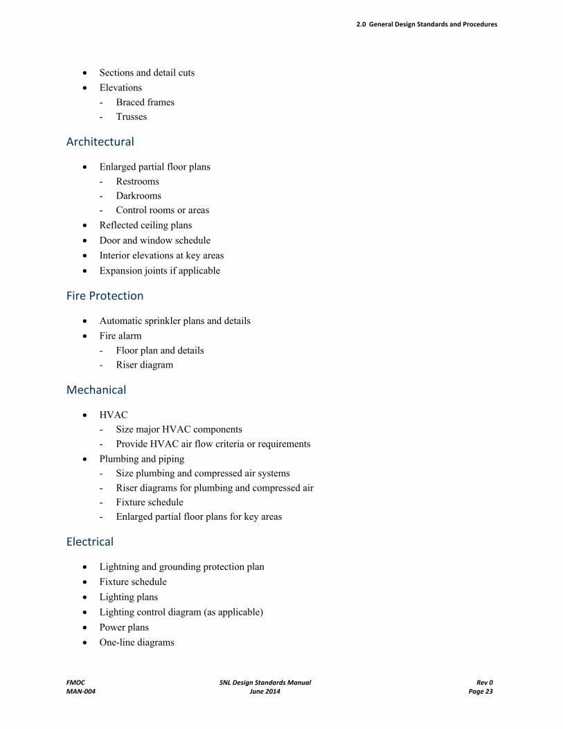
2.0 General Design Standards and Procedures
FMOC SNL Design Standards Manual Rev 0MAN-004 June 2014 Page 23
Sections and detail cuts
Elevations
- Braced frames
- Trusses
Architectural
Enlarged partial floor plans
- Restrooms
- Darkrooms
- Control rooms or areas
Reflected ceiling plans
Door and window schedule
Interior elevations at key areas
Expansion joints if applicable
Fire Protection
Automatic sprinkler plans and details
Fire alarm
- Floor plan and details
- Riser diagram
Mechanical
HVAC
- Size major HVAC components
- Provide HVAC air flow criteria or requirements
Plumbing and piping
- Size plumbing and compressed air systems
- Riser diagrams for plumbing and compressed air
- Fixture schedule
- Enlarged partial floor plans for key areas
Electrical
Lightning and grounding protection plan
Fixture schedule
Lighting plans
Lighting control diagram (as applicable)
Power plans
One-line diagrams
2.0 General Design Standards and Procedures
FMOC SNL Design Standards Manual Rev 0MAN-004 June 2014 Page 24
Detail drawings
Panel schedules
Updated calculations and coordination study
Telecommunications
All drawings listed in the Telecommunications Systems Design Manual can be accessed on the Standards Program website.
Security
Access control plans and details
Intrusion alarm plans and details
2.11.2 Specifications
Provide complete construction specifications prepared in accordance with the procedures in this manual.
2.11.3 Design Analysis
Provide final calculations with all background source material. This material must be neatly indexed and bound.
2.11.4 Cost Estimate
Submit the Final Construction Cost Estimate. The estimate must be prepared per the requirements noted in DOE Order 430.1-1, Cost Estimating. Additional direction may be provided in the design criteria. Youmust organize and segregate the estimate so that all exterior work is identified in a separate category. SFE must be included and identified as a separate category.
2.11.5 Energy Conservation Report
Submit a Final Energy Conservation Report (as required by design criteria) containing the results of energy consumption calculations for the base-case building and the results of the energy analysis and life-cycle cost analysis for any energy conservation alternatives. Deliver complete electronic files (Microsoft Word and Excel) and data files of computer calculations such that SNL/NM could achieve the same results.
2.11.6 Bid Support
Prior to award of construction contract, you must support the SNL/NM project team in the following areas:
Attendance at the prebid conference
Responses to bidders' requests for information (RFIs)
Correction of design errors or omissions in the form of prebid addendums
2.0 General Design Standards and Procedures
FMOC SNL Design Standards Manual Rev 0MAN-004 June 2014 Page 25
Possible review of certain elements of the construction proposals prior to Award of Contract
2.12 Title III Requirements
You must provide Title III services and deliverables (as noted in the contract) to include the following:
Responses to construction contractor RFIs
Review and approval of descriptive submittals
Updated electrical Coordination Study (if required; see 2.12.2)
Resolution of constructability change orders
On-site representation at the construction site
Attendance at construction progress meetings
Provide information for Safety Analysis Report
Site observations
You must create the following as-built documents as part of Title III services (as noted in the contract):
2.12.1 As-Built Drawings
Gather construction as-built notes from the General Contractor and incorporate these notes into the record CAD files.
2.12.2 Calculations
Update the calculations books with any changes required during the course of construction. If the submitted electrical power equipment is different from that which was specified and designed against, perform an updated Coordination Study based on the submitted equipment. If the submitted equipment cannot meet the coordination requirements, reject the submittals.
2.12.3 Correspondence
Deliver all communications and memos that contain pertinent final information to the SDR for record purposes. Organize the sheets in a chronological order of the life of the project.
2.12.4 Descriptive Submittals
Deliver to the SDR all descriptive submittals generated during Title III that were not available during Title II or earlier, such as shop drawings, catalog cuts, Material Safety Data Sheets, and materials information, such as sample boards and maintenance manuals. Organize the descriptive submittals in chronological order by discipline.
2.13 Required Document Quantities for Title I, II, and III
The number of documents to submit to Facilities Engineering for review at Title I and Title II, and for reference at Title III, varies according to project scope and customer organization involvement. In some
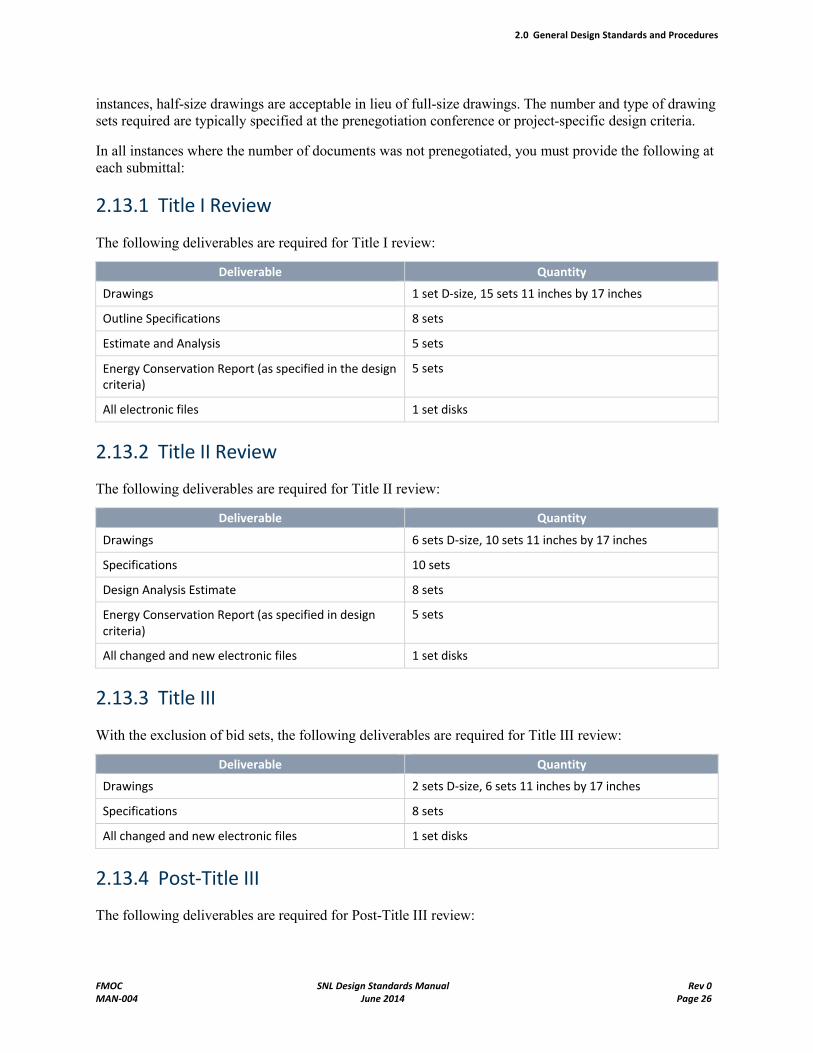
2.0 General Design Standards and Procedures
FMOC SNL Design Standards Manual Rev 0MAN-004 June 2014 Page 26
instances, half-size drawings are acceptable in lieu of full-size drawings. The number and type of drawing sets required are typically specified at the prenegotiation conference or project-specific design criteria.
In all instances where the number of documents was not prenegotiated, you must provide the following at each submittal:
2.13.1 Title I Review
The following deliverables are required for Title I review:
Deliverable Quantity
Drawings 1 set D-size, 15 sets 11 inches by 17 inches
Outline Specifications 8 sets
Estimate and Analysis 5 sets
Energy Conservation Report (as specified in the design criteria)
5 sets
All electronic files 1 set disks
2.13.2 Title II Review
The following deliverables are required for Title II review:
Deliverable Quantity
Drawings 6 sets D-size, 10 sets 11 inches by 17 inches
Specifications 10 sets
Design Analysis Estimate 8 sets
Energy Conservation Report (as specified in design criteria)
5 sets
All changed and new electronic files 1 set disks
2.13.3 Title III
With the exclusion of bid sets, the following deliverables are required for Title III review:
Deliverable Quantity
Drawings 2 sets D-size, 6 sets 11 inches by 17 inches
Specifications 8 sets
All changed and new electronic files 1 set disks
2.13.4 Post-Title III
The following deliverables are required for Post-Title III review:
2.0 General Design Standards and Procedures
FMOC SNL Design Standards Manual Rev 0MAN-004 June 2014 Page 27
Deliverable Quantity
Drawings, as-built 5 sets 11 inches by 17 inches, 1 set disks
All changed and new electronic files 1 set disks
Facilities Engineering returns Title I review marked-up documents for use during Title II. When submitting Title II, return the Title I markups to the SDR, who returns Title II markups for use in making final corrections to the bid documents. You must then return Title II markups along with original drawings for signoff by the SDR.
2.14 Quality Assurance
For each major project (typically line-item projects and above), the SNL/NM Project Lead is responsible for developing a Quality Assurance (QA) Plan as defined in the design criteria. The degree of risk identified in the project's Risk Assessment Plan determines the extent of the QA Plan. Typical elements of the plan include, but are not limited to, design documents review and control, construction documents review and control, construction tests and inspections, change order review and control, facility acceptance and transfer, and completed project documents distribution.
Personnel in the following disciplines, in addition to the customer, should be given the opportunity to review and comment in their areas of expertise for projects:
SNL/NM Project Lead
Building Management
Fire Protection
Safety, Industrial Hygiene, Radiation Protection, Asbestos/Lead Abatement
Architecture
Electrical and Structural Systems Engineering
Mechanical and Civil Systems Engineering
Elevators and Cranes/Hoists
Electrical Systems
Mechanical Systems
Building Mechanics, Facilities Control System
Roofing
Door Hardware
Landscaping, Irrigation, Roads
Custodial Services
Construction Inspection and Acceptance
Physical Security
Electronic Security
Telecommunications Operations
Loading Docks
Docks and Receiving Rooms
Mail Services
2.0 General Design Standards and Procedures
FMOC SNL Design Standards Manual Rev 0MAN-004 June 2014 Page 28
Hazardous and Solid Waste
ES&H Customer Support
Documentation of the quality assurance process is initiated and maintained by the SNL/NM Project Lead. You may be delegated to host part of the process as part of their task.
2.14.1 FMOC Quality Assurance Review Process
Line-item projects, general plant projects (GPPs), expense-funded projects with a construction budget of $250,000 or more, and specific projects with unique ES&H requirements require a multidisciplinary QA review including the customer as well as the applicable disciplines listed in the previous section. This review is typically performed during the development of the CDR and the design criteria, and with the submittal of the Title I (approximately 30% completion) and Title II (100% completion) designs. The intent of the review is to ensure that the required percent of the design is complete and compliant with all applicable codes and orders. The reviews should also confirm that the customer's requirements are satisfied in the most cost effective manner. This review does not relieve you of the required internal reviews prior to submitting your work to SNL/NM.
There are a number of ways to conduct an effective QA review, including the SNL/NM Project Leadsending the documents to all of the reviewers, providing the documents in a central location at designated times, holding a workshop with the reviewers to present the project and solicit comments, or a combination of these. The SNL/NM Project Lead determines the most effective method to conduct the reviews considering the project budget and schedule. In all instances the SNL/NM Project Lead provides notice to the reviewers of the impending review and sufficient amount of time for review.
2.14.2 Design Package Quality Assurance Review
The FMOC Design Package Quality Assurance Review Form (FDPQARF) is initiated by the SNL/NM Project Lead and delivered to the reviewers to record his or her comments. The reviewers must mark all comments on the FDPQARF because these sheets serve as the permanent record of the review. After reviewing comments, the SNL/NM Project Lead provides a written response back to the reviewer on all comments. Reviewers' comments that are adopted in their entirety are so noted on the FDPQARF. If a comment is not adopted or is adopted with exceptions, the SNL/NM Project Lead notes the action and the reason for exception on the FDPQARF or on an attached sheet, and returns it to the reviewer. The project design team meets with the reviewers, individually or as a group, as needed to discuss the comments or to resolve any disagreements.
After all comments have been reviewed, the SNL/NM Project Lead is responsible for resolving conflicting comments and consolidating the responses into a single electronic document to be returned to you.
2.14.3 QA Process and A/E Liability
The QA process is a tool to assist the project team in finding errors and omissions; however, the absence of comments on a specific issue from SNL/NM does not release you from fulfilling all contractual requirements.
2.0 General Design Standards and Procedures
FMOC SNL Design Standards Manual Rev 0MAN-004 June 2014 Page 29
2.15 Project Closeout
The SNL/NM Project Lead must participate in elements of project closeout. These elements include, but are not limited to, Facility Acceptance, Final Cost Report Process, Contracts Close-out and Contractor Evaluations, and Record files.
2.15.1 Facility Acceptance
The project design team must participate in the final construction walk through, preparation of as-built drawings, and completion of documentation.
2.15.2 Final Cost Report Process
This process establishes policies, procedures, responsibilities, and guidance for the preparation of line-item and general plant project Cost Reports. The Final Cost Report on a construction project should be completed as close to the date of beneficial occupancy as possible but not to exceed six months after the facility is in service. Beneficial occupancy occurs when a building or structure is occupied by the technical or administrative organization for which it was intended, although all equipment may not be installed.
Responsibilities of the SNL/NM Administrative Support Office
The following are the responsibilities of the SNL/NM Administrative Support Office:
Serve as the coordinator in gathering all the necessary information from the A/Es, the design engineers, the line organization, the financial system, and any others required for the timely preparation and issuance of Final Cost Reports on line-item and GPP construction projects.
Monitor the closing of all purchase orders related to projects that have been beneficially occupied.
Work with the SNL/NM Project Lead and design engineers to determine how purchase order costs should be aggregated to best fit the engineer's descriptive write-up for the Final Cost Report.
Work with the SNL/NM Project Lead and design engineers in preparation of their portion of the Final Cost Reports on Construction Projects. A list of all purchase orders applicable to the project along with the associated cost must be provided.
Provide the design engineers with suggested format and cost breakdown for their write-ups for Final Cost Reports. All Final Cost Reports are different. They cannot follow the same format used for constructing a new building. The Administrative Support Office has on file several Final Cost Reports that have been accepted by the DOE Sandia Field Office (DOE/SFO), and provide examples to use as a format guide.
Finalize preparation of the Final Cost Report and transmittal letter to DOE/SFO.
Responsibilities of SNL/NM Project Lead
The following are the responsibilities of the SNL/NM Project Lead:
Complete the Final Cost Reports with the assistance of the Systems Engineers.
2.0 General Design Standards and Procedures
FMOC SNL Design Standards Manual Rev 0MAN-004 June 2014 Page 30
Work with the line organizations and provide the Business Office with equipment write-ups and/or listings for equipment procured by them with line-item construction funds. The Administrative Support Office provides the purchase order listing for this exercise.
Provide explanations as to cost and schedule variances as compared to the original directive.
Verify the SNL project team has received all final project files.
Responsibilities of SNL/NM Line Organization
The line organization works with the SNL/NM Project Lead in providing the Administrative Support Office with equipment write-ups, listings of equipment procured by them with line-item construction funds, or both.
2.15.3 Contract Closeouts and Contractor Evaluations
The project team participates in the performance evaluation of A/E and construction contractors as shown on Standard Forms 1420, Construction Contracts, and 1421, Architect-Engineer.
2.15.4 Record Files
The SNL/NM project team participates in the handling of the project records, as directed by the SNL/NM Project Lead, for permanent retention by the following FMOC functions:
Maintenance Engineering
Systems Engineering Document Management
2.16 Safety Requirements
The SNL project team members, including Project Lead, operations leads, architects, engineers and other design professionals, must incorporate safety into all project designs to meet current OSHA 1910, 1926, and SNL's corporate requirements for fall protection. All safety related portions of a design, including design drawings, specifications, code footprint, and calculations, must bear the seal, signature, and date of a New Mexico-licensed design professional as required and regulated by the New Mexico Regulation and Licensing Department's professional discipline Boards.
2.16.1 Fall-Protection Design Requirements for Rooftop Parapets
All rooftop parapets must be 42" minimum above the finished roof surface to the top of the coping cap. Railings, tie-offs, or other means of fall protection must meet current OSHA and project team requirements.
2.16.2 Fall-Protection Design Requirements for Sloping Roofs
For all sloping roofs, fall-protection design must incorporate an engineered solution for tie-offs or railings and must meet current OSHA and project team requirements.
2.0 General Design Standards and Procedures
FMOC SNL Design Standards Manual Rev 0MAN-004 June 2014 Page 31
2.16.3 Other Fall-Protection Design Requirements
The design of all new buildings, additions, and renovations must include an engineered solution for skylights, roof-access hatches, roof-access ladders, or roof-access stairs that meets current OSHA and project team requirements.
3.0 Civil Design
FMOC SNL Design Standards Manual Rev 0MAN-004 June 2014 Page 32
3.0 Civil Design
3.1 Introduction
This chapter describes the criteria, standards, and regulations for designing civil systems at Sandia National Laboratories in New Mexico (SNL/NM). These are the minimum acceptable criteria and standards necessary to result in system designs with satisfactory functional characteristics, durability, and operational suitability. Strive for the best design to suit the circumstances involved, and make that design reflect sound professional judgment at all times. Coordinate efforts with team members from other project disciplines to support the integrated site design approach. (See Section 2.2 in Chapter 2, "General Design Standards and Procedures.")
The following minimum design standards apply to the civil work phase on all projects. For general requirements for all project phases, see Chapter 2, "General Design Standards and Procedures.”
3.2 Construction Drawings
This section describes the various drawings, maps, plans, and profiles required for designing civil systems at SNL/NM.
3.2.1 Area Map and Vicinity Map
Prepare a map to show a zoomed-out view of the project site in relation to its location on Kirtland Air Force Base (KAFB). The area map must have a scale of 1 inch = 1 mile or larger.
In addition to the area map, prepare a vicinity map to a maximum scale of 1 inch = 200 feet, or as otherwise directed by the Sandia Delegated Representative (SDR). Where applicable, show haul routes, disposal areas, recycle centers, stockpile locations, contractors' access gate, security checkpoints, major street names, and other pertinent information.
3.2.2 Plans and Profiles
Prepare plan and profile sheets for the following:
Water (domestic and fire protection), storm drain, sanitary sewer, gas, chilled water loops, and recycle/recovery loops
Electrical overhead and underground electrical conduit runs
Other large cables when pulled into long raceway runs
Road construction and paving improvements, including utilities within roadways
All duct banks and buried conduit
All service laterals
Profiles must have an expanded vertical scale and show the line continuous in profile with break lines to depict change in direction, if necessary. Run all stationing on plan and profile sheets from left to right regardless of the direction of the north arrow. Draw associated plan views to detail portions of the plan not adequately detailed on the plan portion of the plan and profile. Underground utility profiles must include the vertical locations of existing underground utilities to minimize conflicts.
3.0 Civil Design
FMOC SNL Design Standards Manual Rev 0MAN-004 June 2014 Page 33
Prepare plans, profiles, or cross-sections to describe paving improvements and extensive grading workadequately. Where appropriate, minor grading and shaping may be shown on a site plan by spot elevations in lieu of a profile.
3.2.3 Site Plans
Prepare site plans to a scale of 1 inch = 20 feet, unless otherwise noted in the design criteria, and orient the plans as listed in the SNL CADD Standards Manual. Show coordination relating to existing underground utilities, architectural features, mechanical equipment, electrical equipment, landscaping (including vegetation and irrigation lines), and other site features that might affect the project on all site plans to guide trenching and excavation. Accurately locate the existing underground utilities in the construction area.
Do not rely solely on SNL/NM Geographical Information System (GIS) mapping for accuracy. As a minimum, use the GIS maps along with a site visit to verify the accuracy of the information. Collect critical measurements during the site visit or secure the services of a surveyor.
3.2.4 Underground Utilities
Develop a plan to locate and document the depth of cover and dimensions of existing underground utilities where it is pertinent to do so along new utility routes and in areas to be excavated or graded. Provide utility locating methods and services as indicated in the project scope. Services may include potholing using vacuum excavation or ground-penetrating radar as required to properly design the project. Submit a copy of all utility pothole logs to Facilities Management and Operations Center (FMOC) Infrastructure Engineering. Request a copy of up-to-date existing site data files following the process outlined in the SNL CADD Standards Manual. Review current global positioning system (GPS) data in the area of the project to minimize subsurface utility investigation requirements.
Add the following note to the general notes section of the title sheet for projects that include existing underground utilities work:
CautionWhen Excavating
The locations of all underground utilities shown are approximate. The contractor must verify the horizontal and vertical location of all underground utilities prior to the start of construction. The contractor must not interfere with utility line operations and must coordinate all work affecting existing utilities with SNL/NM for each utility, and must notify the SNL/NM Construction Manager (CM) promptly of any problems or conflicts encountered. Further, the contractor must obtain an excavation permit prior to start of excavation. See the project specifications for other requirements.
3.2.5 Drawings Required for Construction
The following sections provide lists of drawings required for a typical project. To illustrate the scope of a project, an approximate list of the plans and drawings required is provided in the design criteria for each discipline. If a project does not have design criteria, see Chapter 2, "General Design Standards and Procedures," of this Design Standards Manual for information on drawing organization and arrangement of the overall construction drawings set. The CADD design files for all projects must conform to the requirements of the CADD Standards Manual. Infrastructure drawings and organization within the construction drawings set include, but are not limited to, the following:
3.0 Civil Design
FMOC SNL Design Standards Manual Rev 0MAN-004 June 2014 Page 34
1. Title Sheet: Include job title, project number, contract number, vicinity map, and index of drawings. If the index is extensive it may be placed on a separate Index of Drawings sheet.
2. Vicinity Map: Map showing a zoomed-out view of the project site in relation to its location on KAFB at a scale of 1 inch = 1 mile or larger (can be combined with Title Sheet or Site Plan for small jobs).
3. Site Layout Plan: Show general notes, limits of construction, fences, access, storage areas, street names, alignment of temporary fencing enclosing work areas, and other items needed to convey accurately this portion of the design to the contractor. Provide SNL/NM control monuments with ties to new construction, if a site survey is not provided in the design drawings.
4. Traffic Control Plan: Provide traffic control for pedestrian and vehicular traffic phased with the demolition and construction activities of the project.
5. Removal or Demolition Plan: Show all existing facilities and infrastructure to be removed and pertinent phasing. If required for modifications work, include a site survey.
6. Grading Plan: Show the buildings considered in the contract, the surrounding area, existing topography (including contours at an appropriate interval), and required elevations referenced to an existing benchmark. Show finished grading and existing grades to determine cut and fill. Show street centerlines properly referenced to the coordinate system. Show utilities, unless separate utility site plans are included in the set.
7. Drainage Plan: Show drainage basins, flow paths, rates, and finished contours unless submittedin a separate drainage report.
8. Exterior Utilities Plan: Show all existing and new utilities, including irrigation lines, where feasible. Include a legend for all existing and proposed utilities.
9. Plan and Profile Drawings: Provide plan and profile drawings for all utilities unless otherwise directed by the Infrastructure Engineer. Show the plan and profile of road construction, as well as survey data and the existing grade at centerline (not required for short access or service drives). Show the plan and profile of new utilities as well as existing and finished grades at centerline.
10. Detail Sheets and Area Plans: For road construction, show typical roadway cross-section, intersection plan with spot elevations as needed, turnouts, special paving area plans, pavement section details, and structure details. For utilities show all special connections, utility vaults, orother information that cannot be shown on the utility plans and profiles.
11. Cross-Section Sheets: For road construction, cut and fill cross-sections at specified stations when requested by the SDR.
12. Exterior Civil Details: Provide reference to standard details or show details for civil site work. All details must be labeled descriptively, and cross-referenced to the applicable plan drawings. See the CADD Standards Manual for additional CADD requirements.
13. Site Planting and Irrigation Plans and Details: Show all required information on separate sheets. Follow the advice in applicable sections of the Campus Design Guidelines (CDG) for SNL/NM.
3.0 Civil Design
FMOC SNL Design Standards Manual Rev 0MAN-004 June 2014 Page 35
3.3 Site Modification and NEPA Review Processes
All site modifications must follow FMOC process PCS.056, Site Modification Review. All utility connections must be submitted on a site plan to FMOC Infrastructure Engineering for approval.
Projects at SNL must give consideration to the environment early in the project planning stage. This consideration is documented through the National Environmental Protection Act (NEPA) module of the Integrated Safety Management System (ISMS). Specific SNL requirements for complying with NEPA regulations are found in corporate procedure ESH100.1.EP.2, Implement NEPA, Cultural Resources, and Historic Properties Requirements. Contact the Project Lead for additional guidance.
Construction activities within 100 feet of any monitoring well must be coordinated with the SNL/NM Groundwater Protection Program Project Lead. Soil-disturbing construction activities are prohibited with 50 feet of any monitoring well. Any borehole installation within half the distance from the ground surface to the uppermost occurrence of groundwater must be coordinated with the SNL/NM Groundwater Protection Program Project Lead.
3.4 Exterior Utilities
When designing exterior utilities, consider possible future extensions and utility demands. The SNL/NM project team provides direction to allow utilities to be sized to meet future demands. Size and terminate utility systems to accommodate future connections. In general, if expansion is planned, extend utilities to the edge of the site or to a point where connection can be made without damage or disruption to the utility or adjacent structures. Establish utility corridors with each utility having a defined location within the corridor to optimize land use and provide adequate utility separation. Consult with FMOC Infrastructure Engineering during conceptual design to ensure proper connections and sizing. The Infrastructure Engineer responsible for each system reviews and approves all connections to the system in the preliminary and final design phases.
3.4.1 Underground Water Lines
This subsection describes criteria and standards for the design of water distribution systems. It does not cover the criteria necessary for the design of major transmission lines, wells, pumping facilities, or reservoirs. The FMOC Infrastructure Engineering department must approve in advance any departure from the criteria.
All water lines and their connections to existing water lines must be designed and shown on a plan and profile drawing. Drawings must show all details, including required fittings and joint restraints.
Locate distribution lines in a utility corridor whenever possible.
All lines 6 inches or larger must be cement-lined ductile iron pipe in accordance with SNL/NM construction standard specifications and standard drawings. Use of PVC pipe is not allowed for lines 6inches or larger in diameter.
Size the water mains based on requirements from FMOC Infrastructure Engineering. Service laterals must be sized by the Design Engineer according to the code requirements for the facility. Branches off the main water line must have a gate valve in a valve box to isolate the building or facility from the main. Where possible, the potable water service is to be a branch off the fire service line, with its own gate valve in a yard box.
3.0 Civil Design
FMOC SNL Design Standards Manual Rev 0MAN-004 June 2014 Page 36
The minimum depth of cover over all water lines is 36 inches.
The trench for pipe installation must be similar to Type 4 as defined by American Water Works Association (AWWA) C600. Pipe must be bedded in 4 inches of sand, gravel, or crushed stone. Backfill must be compacted to the top of the pipe to approximately 80 percent Standard Proctor, American Association of State Highway and Transportation Officials (AASHTO) T-99.
Unless approved by FMOC Infrastructure Engineering, connections larger than 2 inches must be made by cutting the supply main and inserting a standard tee. The maximum allowable tap using a tapping saddle is 2 inches. When approved by FMOC Infrastructure Engineering for connections larger than 2 inches, tapping sleeves must be used. The size of the tapping sleeve is limited to one half of the nominal pipe diameter. Connections exceeding this requirement must be made by inserting a tee. See SNL Standard Specification 02665, Underground Water Lines for Domestic and Fire Protection Systems, for additional tapping requirements.
When the water main supply line is 8 inches or larger, the minimum size fire protection line is 8 inches for any sprinkler system supplying a building designed for Ordinary Hazard Group II or greater. Buildings, T-buildings, mobile offices, and trailers smaller than 10,000 square feet are exempt from the 8-inch-minimum fire line requirement.
Do not run fire protection mains under buildings, including temporary structures, such as mobile offices or trailers.
Locate post-indicator valves (PIVs) on fire protection lines no closer than 40 feet and no farther than 100 feet from the building. If this distance is not feasible, the FMOC Fire Protection Engineer can grant authority to locate PIVs at different distances. Post-indicator valve supervisory switches must be installed for all PIVs and connected to the building fire alarm system. The devices must be electrical; single-pole, double-throw, with normally closed contacts and include design that signals the controlled post-indicator valve is in other than a fully open position.
Three-way fire hydrants with a curb box valve must be provided within 50 feet of all fire department connections. Fire hydrant spacing must not exceed 300-foot intervals. The FMOC Infrastructure Engineering department determines fire hydrant spacing in remote areas and on transmission lines.
All pipes passing under railroad tracks must be encased in a protective metal sleeve, sized at least 2 inches larger in diameter than the water line. Support the pipe in the sleeve per manufacturer's instructions. Seal the ends of the sleeve with resilient caulking material or a preformed plastic boot.
Mechanically restrained joints must be designed and detailed on the construction drawings. See SNL/NM Standard Drawing WU5005STD.
The design of valves within the water system must conform to the following criteria:
Valve Spacing
- 2,600 feet maximum between inline valves for lines 16 inches and larger.
- 1,200 feet maximum between inline valves for lines 14 inches and smaller.
At the intersection of water lines, the distribution lines in all directions must be valved.
Fire hydrant legs from mains must be valved.
Valve Location: Avoid locating valves under parking spaces or locations where the valves mightbe inaccessible, in sidewalk ramps, and next to fences.
Valve Types
3.0 Civil Design
FMOC SNL Design Standards Manual Rev 0MAN-004 June 2014 Page 37
- Valves 12 inches and smaller must be gate valves.
- Valves 14 inches and larger must be butterfly valves.
Valve Sizing
- All valves must be the same size as the main lines.
Air-Relief Valves
- No air-relief valves or air-relief hydrants are required on lines 8 inches or smaller where there are services on the line. On distribution lines greater than 8 inches, sizing and location of air-relief hydrants must be coordinated with FMOC Infrastructure Engineering.
The SNL Project Lead notifies Environmental Programs and Assurance (4143) when a project at SNL/NM involves new construction or modification of the SNL/NM Water Distribution System. This notification allows SNL/NM to meet obligations related to Safe Drinking Water Act requirements for the operation and maintenance of a public water system on KAFB. Contact the SNL/NM FMOC Water System Engineer for additional guidance and information.
3.4.2 Sanitary Sewer
This subsection describes the criteria, standards, and regulations for the design of sanitary sewer systems. It does not cover the criteria necessary for design of major interceptor sewer, lift station, sewer line rehabilitation, or wastewater monitoring facilities.
3.4.2.1 Septic Tanks and Holding Tanks
If a sewer main is not economically feasible, install a holding tank. Do not design holding tanks for flows greater than 375 gallons per day. Holding tanks should be accessible and capable of supporting wheel, backfill, and other loads if buried.
Septic tanks and dry wells must not be used without the written consent of SNL/NM Environmental Operations.
3.4.2.2 Engineering Design Criteria
Design sanitary sewers to maintain velocities that provide self-cleaning action. See the table in Subsection3.4.2.4 for minimum slopes that provide minimum velocities. Avoid velocities above 10 feet per second because of possible long-term damage to the pipe. New facility sewer connections located several hundred feet from the existing system should provide capacity for future expansion. At all horizontal changes in the alignment, provide manholes in lines that are 8 inches or larger.
Ensure by visual inspection; drawing research; field survey, dye testing, or both; that plumbing connections are made to appropriate sanitary sewer piping. Do not make piping connections that result in the flow of the sanitary sewer to the storm drain system, and do not connect storm drains to sanitary sewers.
3.4.2.3 Manhole Criteria
Conform to these criteria for manholes:
Avoid locating manholes in natural or manmade drainage swales, curb lines, and parking lanes and spaces.
3.0 Civil Design
FMOC SNL Design Standards Manual Rev 0MAN-004 June 2014 Page 38
Standard minimum manhole depth is 6 feet, measured from the rim to invert. The FMOCInfrastructure Engineering must approve deviations.
The required inside diameter for a manhole is determined as follows:
- Minimum inside diameter is 4 feet.
- A minimum 9-inch-wide shelf must be provided on each side of each main line within the manhole.
- Where the main flow changes direction at a manhole, the manhole must be large enough so the centerline radius of curvature of the flow invert is larger than the pipe diameter.
Flow is not be permitted to change horizontal flow directions by more than 90 degrees in a manhole.
Invert elevations must be called out for each inlet and outlet at a manhole.
The drop across manholes is to be as follows:
- Where the main flow does not change direction at the manhole, the design must provide (1) A slope across the manhole at least equal to the average of the slopes of the incoming and outgoing lines, and (2) a minimum drop of 0.05 feet for lines 36 inches and smaller.
- Where the main flow changes direction at the manhole, the design must maintain the average of the slopes of the incoming and outgoing lines and compensate for the loss of velocity head caused by the turn. (1) The slope component must be equal to the average of the slopes of the incoming and outgoing lines times the diameter of the manhole. (2) The velocity head component must be determined using the following formula:
- hb=Kb(V2)/2g
- Where
- hb = required drop to compensate for loss of velocity head (feet)
- Kb bend coefficient; use 0.4 for 90 degree turn, 0.32 for 45 degree turn, and linear proportioning for other deflection angles (dimensionless)
- V = design velocity of incoming line based on design flow in feet/sec
- g = 32.17 feet/sec2
(1) The total drop required through the manhole is the sum of the slope component and velocity head component. (2) The minimum drop through a manhole must be 0.10 feet.
- Where flows converge at a manhole, the inverts should be designed to produce a smooth water surface at design flow with no backwater conditions in any of the incoming lines. Avoid excessive drops that cause turbulence.
- The use of drop connections to manholes (drop manholes) requires FMOC Infrastructure Engineering approval. Drop manholes must conform to SNL/NM standard drawings.
Drop manholes and other manholes with high potential for sulfide gas generation must be designed with corrosion-resistant coating, such as epoxy on interior walls, when directed by FMOC Infrastructure Engineering.
The maximum distance allowed between manholes is 450 feet.
When an interim line extension is to be built for a distance less than the reasonable spacing for a manhole installation, FMOC Infrastructure Engineering can allow installation of a "temporary,"8-inch diameter, end-of-line cleanout in lieu of a manhole. The design drawings for such installation must provide a design to the next anticipated, upstream manhole location, with line and manhole beyond the temporary cleanout depicted as "Future."
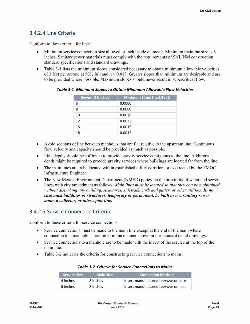
3.0 Civil Design
FMOC SNL Design Standards Manual Rev 0MAN-004 June 2014 Page 39
3.4.2.4 Line Criteria
Conform to these criteria for lines:
Minimum service connection size allowed: 4-inch inside diameter. Minimum mainline size is 6 inches. Sanitary sewer materials must comply with the requirements of SNL/NM construction standard specifications and standard drawings.
Table 3-1 lists the minimum slopes considered necessary to obtain minimum allowable velocities of 2 feet per second at 50% full and n = 0.013. Greater slopes than minimum are desirable and are to be provided where possible. Maximum slopes should never result in supercritical flow.
Table 3-1 Minimum Slopes to Obtain Minimum Allowable Flow Velocities
Sewer ID (inches) Minimum Slope (feet/foot)
6 0.0060
8 0.0060
10 0.0028
12 0.0022
15 0.0015
18 0.0012
Avoid sections of line between manholes that are flat relative to the upstream line. Continuous flow velocity and capacity should be provided as much as possible.
Line depths should be sufficient to provide gravity service contiguous to the line. Additional depth might be required to provide gravity services where buildings are located far from the line.
The main lines are to be located within established utility corridors or as directed by the FMOCInfrastructure Engineer.
The New Mexico Environment Department (NMED) policy on the proximity of water and sewer lines, with city amendment as follows: Main lines must be located so that they can be maintained without disturbing any building, structures, sidewalk, curb and gutter, or other utilities. In no case must buildings or structures, temporary or permanent, be built over a sanitary sewer main, a collector, or interceptor line.
3.4.2.5 Service Connection Criteria
Conform to these criteria for service connections:
Service connections must be made to the main line except at the end of the main where connection to a manhole is permitted in the manner shown in the standard detail drawings.
Service connections to a manhole are to be made with the invert of the service at the top of the main line.
Table 3-2 indicates the criteria for constructing service connections to mains.
Table 3-2 Criteria for Service Connections to Mains
Service Size Main Size Connection Method
4 inches 8 inches Insert manufactured tee/wye or core drill main and install saddle6 inches 8 inches Insert manufactured tee/wye or install manhole
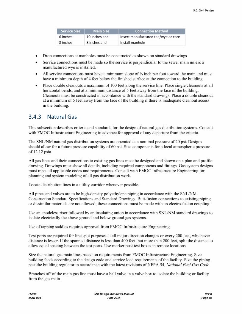
3.0 Civil Design
FMOC SNL Design Standards Manual Rev 0MAN-004 June 2014 Page 40
Service Size Main Size Connection Method
6 inches 10 inches and greater
Insert manufactured tee/wye or core drill main and install saddle8 inches 8 inches and
greaterInstall manhole
Drop connections at manholes must be constructed as shown on standard drawings.
Service connections must be made so the service is perpendicular to the sewer main unless a manufactured wye is installed.
All service connections must have a minimum slope of ¼ inch per foot toward the main and must have a minimum depth of 4 feet below the finished surface at the connection to the building.
Place double cleanouts a maximum of 100 feet along the service line. Place single cleanouts at all horizontal bends, and at a minimum distance of 5 feet away from the face of the building. Cleanouts must be constructed in accordance with the standard drawings. Place a double cleanout at a minimum of 5 feet away from the face of the building if there is inadequate cleanout access in the building.
3.4.3 Natural Gas
This subsection describes criteria and standards for the design of natural gas distribution systems. Consult with FMOC Infrastructure Engineering in advance for approval of any departure from the criteria.
The SNL/NM natural gas distribution systems are operated at a nominal pressure of 20 psi. Designs should allow for a future pressure capability of 60 psi. Size components for a local atmospheric pressure of 12.12 psia.
All gas lines and their connections to existing gas lines must be designed and shown on a plan and profile drawing. Drawings must show all details, including required components and fittings. Gas system designs must meet all applicable codes and requirements. Consult with FMOC Infrastructure Engineering for planning and system modeling of all gas distribution work.
Locate distribution lines in a utility corridor whenever possible.
All pipes and valves are to be high-density polyethylene piping in accordance with the SNL/NM Construction Standard Specifications and Standard Drawings. Butt-fusion connections to existing piping or dissimilar materials are not allowed; these connections must be made with an electro-fusion coupling.
Use an anodeless riser followed by an insulating union in accordance with SNL/NM standard drawings to isolate electrically the above ground and below ground gas systems.
Use of tapping saddles requires approval from FMOC Infrastructure Engineering.
Test ports are required for line spot purposes at all major direction changes or every 200 feet, whichever distance is lesser. If the spanned distance is less than 400 feet, but more than 200 feet, split the distance to allow equal spacing between the test ports. Use marker post test boxes in remote locations.
Size the natural gas main lines based on requirements from FMOC Infrastructure Engineering. Size building feeds according to the design code and service load requirements of the facility. Size the piping past the building regulator in accordance with the latest revisions of NFPA 54, National Fuel Gas Code.
Branches off of the main gas line must have a ball valve in a valve box to isolate the building or facility from the gas main.
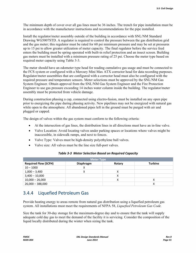
3.0 Civil Design
FMOC SNL Design Standards Manual Rev 0MAN-004 June 2014 Page 41
The minimum depth of cover over all gas lines must be 36 inches. The trench for pipe installation must be in accordance with the manufacturer instructions and recommendations for the pipe installed.
Install the regulator/meter assembly outside of the building in accordance with SNL/NM Standard Drawing WG5007STD. A regulator is required to control the pressure between the gas distribution grid and the gas meter; this regulator must be rated for 60 psi minimum pressure and may be set at pressures up to 15 psi to allow greater utilization of meter capacity. The final regulator before the service feed enters the building must be spring operated with built-in relief protection and an insect screen. Building gas meters must be installed with a minimum pressure rating of 25 psi. Choose the meter type based on required meter capacity using Table 3-3.
The meter should have an odometer type head for reading cumulative gas usage and must be connected to the FCS system or configured with a Mercury Mini Max ATX corrector head for data recording purposes. Regulator/meter assemblies that are configured with a corrector head must also be configured with the required pressure and temperature sensors. Meter selections must be approved by the SNL/NM Gas System Engineer. Obtain approval from the SNL/NM Gas System Engineer and the Fire Protection Engineer to use gas pressure exceeding 14 inches water column inside the building. The regulator/meter assembly must be protected from vehicle damage.
During construction phasing a cap, connected using electro-fusion, must be installed on any open pipe prior to energizing the pipe during phasing activity. New pipelines may not be energized with natural gas while open to the atmosphere. All abandoned pipes left in the ground must be purged with air and plugged or capped.
The design of valves within the gas system must conform to the following criteria:
At the intersection of gas lines, the distribution lines in all directions must have an in-line valve.
Valve Location: Avoid locating valves under parking spaces or locations where valves might be inaccessible, in sidewalk ramps, and next to fences.
Valve Type: Valves must be high-density polyethylene ball valves.
Valve size: All valves must be the line size full-port valves.
Table 3-3 Meter Selection Based on Required Capacity
Meter Type
Required Flow (SCFH) Diaphragm Rotary Turbine
10 – 1000 X
1,000 – 3,400 X X
3,400 – 10,000 X
10,000 – 26,000 X X
26,000 – 388,000 X
3.4.4 Liquefied Petroleum Gas
Provide heating energy to areas remote from natural gas distribution using a liquefied petroleum gas system. All installations must meet the requirements of NFPA 58, Liquefied Petroleum Gas Code.
Size the tank for 30-day storage for the maximum-degree day and to ensure that the tank will supply adequate cold day gas to meet the demand of the facility it is servicing. Consider the composition of the liquid locally distributed during the winter when sizing the tank.
3.0 Civil Design
FMOC SNL Design Standards Manual Rev 0MAN-004 June 2014 Page 42
Locate a regulator, relief valve, capacity gauge, and fill valve under a protective cover on the top of the tank. The exterior regulator must have an automatic shutdown device for excess flow conditions. Select line and regulator size to prevent freeze-up during cold weather usage. Specify an American Gas Association 100-percent shutoff safety pilot and appliance regulator on all appliances.
3.4.5 Storm Drains
Storm drain design must comply with the design portions of Chapter 22 of the City of Albuquerque Development Process Manual for a list of approved design guidance, SNL/NM Construction Standard Specifications and Standard Drawings). The technical guidance that applies includes the following sections:
Hydrology
Hydraulic Design
Channel Treatment Selection Guidelines
Design Grading and Erosion Control
Miscellaneous
See Section 3.6, "Drainage Requirements."
3.5 Site Work
3.5.1 Grading
Prepare a current topographic survey for all construction projects when grading or trenching is required. The topographic survey must be tied into the SNL/NM Survey Control Monuments for establishing x, y, and z (see Section 3.7, "Surveying"). Plan the facilities to fit the topography with a minimum of grading and to preserve the site character in an efficient and economical manner. Site grading must minimize site disturbance by emphasizing conservation of existing natural areas and restoration of previously damaged areas.
In the site grading design provide for adequate surface drainage and preservation of natural terrain by allowing a minimum of earth movement with the objective of balancing cut and fill. To prevent surface drainage from entering or ponding adjacent to the structure, place finished floor elevations with access penetrations sufficiently above the existing ground gradient or the roadway grade. Write an accompanying drainage report to prove these criteria (see Section 3.6, "Drainage Requirements.")
In the site grading design, take into account the need for safety and ease of personnel and vehicular access to the facility. Accessibility to facilities is required for physically handicapped persons in accordance with the ABA Accessibility Standard for Federal Facilities 2006 from the General Services Administration.Bus stops, bus stations, and rail stations are to follow the ADA Standards for Transportation Facilities2006 from the U.S. Department of Transportation.
Design the outside finished grade to slope away from the building at a 5-percent grade for the first 10 feet unless otherwise approved by FMOC Infrastructure Engineering. Extend the 5-percent grade to 20 or 30 feet in areas with highly expansive soil. When site conditions require the use of steep slopes near buildings, provide an area that is at least 6 feet wide at a 5-percent grade away from the building. Indicate these requirements on the grading plan with critical spot elevations and finished contours. When the adjacent outside grade is brought above the building floor level for energy conservation, aesthetic, or
3.0 Civil Design
FMOC SNL Design Standards Manual Rev 0MAN-004 June 2014 Page 43
economic reasons, design the outside finish grade to slope away from the building at a 20 percent minimum grade for at least 5 feet.
3.5.2 Fencing
Design fencing to provide the intended function, such as safety or security. Security fencing is required as a physical demarcation of a security area, for security of classified assets and government property, and to direct flow of personnel and vehicles through designated entry control points. Fencing must be designed in accordance with SNL/NM Construction Standard Specifications and Standard Drawings. Fire department access must be provided during construction and occupancy phases when designing temporary and permanent fencing.
Fences to be used for security purposes must be at least 8-feet high, with fabric a minimum of 11-gauge galvanized steel, and with mesh openings a maximum of 2 inches on each side. The fence must be topped by a minimum of 3 strands of barbed wire on single or double outriggers. Single outriggers must be angled outward from the security area. Double outriggers must be used at Protected Area boundaries. Security fencing must extend to within 2 inches of firm ground or extend below the surface, if the soil is unstable or subject to erosion.
Alternative security fencing is allowed with approval from Physical Security. Alternative fencing must meet the penetration resistance of the standard chain link security fencing. Drawings and calculations of penetration resistance for alternative fencing must be submitted for approval to Physical Security prior to contract acceptance.
Posts bracing and other structural members must be located on the inside of security fences. Wire ties must be of equal tensile strength as that of the fabric.
Locate security fencing with a clear zone along each side of the fence to facilitate intrusion detection and prevent bridging over the fence. Fence must be located a minimum of 20 feet from structures or assets located inside the security area and a minimum of 20 feet from structures located outside the security area. Landscaping must be designed such that plant growth does not impede visual assessment or allow bridging. Consult with a Physical Security representative for the latest standoff requirements.
3.5.3 Gates and Turnstiles
Location of turnstiles and motorized gates must be coordinated with FMOC Infrastructure Engineering to ensure adequate automated access control and other system support.
Use swinging gates for access through security fencing. Use swing gates in other fencing when possible. When rolling gates are required, use a system with an overhead support, if practical. If a cantilevered gate must be used, use a system with an enclosed top rail as a track. Avoid using rollers at grade because dust and water accumulations are a constant maintenance problem.
Gate hardware for security fencing must be brazed, peened, or welded to prevent removal.
Use turnstiles for pedestrian entry control points. A minimum of two single turnstiles and one bypass gate must be used at each entry location, unless within line of sight of another entry point. Tandem turnstiles must not be used because of safety and maintenance concerns.
Additional security fencing requirements, including temporary security fencing, are described in Chapter 11, "Security Design Standards," of this Design Standards Manual.
3.0 Civil Design
FMOC SNL Design Standards Manual Rev 0MAN-004 June 2014 Page 44
3.5.4 Sidewalks
Design sidewalks and walk gradients to provide safe and convenient access, egress, and circulation between facilities. Base the width of sidewalks on anticipated traffic, with a minimum width of 6 feet increasing in 2-foot increments. Sidewalks paralleling curbs in parking areas and those with high pedestrian use must have a minimum width of 6 feet of available walking area. All sidewalk widths must be consistent with ADA/ABA accessibility requirements (see Subsection 3.5.1, "Grading"). Install ramps where required to maintain accessible routes.
Integrate sidewalk design with drainage system and landscape design as much as possible to promote collection, conveyance, and infiltration of stormwater runoff generated from continuous, impervious sidewalk surfaces. In addition, prevent sidewalks from contributing to heat island effects by providing shade from landscaping or locating sidewalks in areas not subject to sustained sunlight. Refer to theCampus Design Guidelines for SNL/NM for more information and requirements on sidewalks and pedestrian path.
3.5.5 Dual Bicycle and Cart Paths
Bicycle and cart paths must be separated from pedestrian sidewalks. The paths must have a minimum width of 12 feet for two-way traffic and 8 feet for one-way traffic, a maximum longitudinal slope of 5%, and a maximum cross slope of 2%. See the Campus Design Guidelines for SNL/NM for further information.
3.5.6 Roads
The criteria for road design must be in accordance with AASHTO A Policy on Geometric Design of Highways and Streets, latest edition. When designing roads and associated drainage systems, take into account soil, geologic, topographic, and climatic conditions, including any special conditions, such as snow removal. Roadways must be designed to accommodate the maximum size of vehicles traveling through the area. During planning and design, carefully consider the timing of road construction, specifically for seasonal conditions. Flexible pavements and curb and gutter must be in accordance with approved standard drawings.
If required, perform studies to estimate the volume and character of traffic during both the construction and operating phases. Controlling vehicle speed within congested areas can permit the profile of roads to conform generally to the ground surface, which allows maximum use of adjacent areas and results in economical road construction costs. The FMOC Infrastructure Engineering department determines speed limits. Reserve sufficient corridor width for anticipated future expansion. Design and plan underground utilities and their construction to minimize interference with road construction and trench cuts in recently paved areas.
Integrate road design with drainage system and landscape design. Consider landscaping and other suitable means of harvesting runoff from roads to promote collection, conveyance, and infiltration into the soil.
For environmental protection, provide adequate drainage and soil stabilization for roads and construction areas. In addition, carefully maintain roadways, ditches, and drainage structures during construction.
Design of emergency vehicle access must conform to fire lane requirements defined in NFPA 1141, the International Fire Code (IFC), and the City of Albuquerque Fire Code, or as might be determined by the SNL Emergency Operations Center.
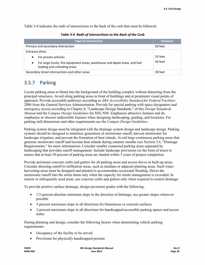
3.0 Civil Design
FMOC SNL Design Standards Manual Rev 0MAN-004 June 2014 Page 45
Table 3-4 indicates the radii of intersections to the back of the curb that must be followed.
Table 3-4 Radii of Intersections to the Back of the Curb
Type of Intersection Distance
Primary and secondary intersection 50 feet
Entrance drive:
For private vehicles
For large trucks, fire-equipment areas, warehouse and depot areas, and fuel loading and unloading areas
25 feet
50 feet
Secondary street intersections and other areas 30 feet
3.5.7 Parking
Locate parking areas to blend into the background of the building complex without detracting from the principal structures. Avoid siting parking areas in front of buildings and at prominent visual points of approach. Provide accessible pathways according to ABA Accessibility Standard for Federal Facilities2006 from the General Services Administration. Provide for special parking with space designators and emergency access according to Chapter 4, "Landscape Design Standards," of this Design Standards Manual and the Campus Design Guidelines for SNL/NM. Emphasize attractive features and de-emphasize or obscure undesirable features when designing landscaping, grading, and locations. For parking stall dimensions and other requirements see the Campus Design Guidelines.
Parking system design must be integrated with the drainage system design and landscape design. Parking systems should be designed to minimize generation of stormwater runoff, harvest stormwater for landscape irrigation, and prevent the formation of heat islands. Avoid large continuous parking areas that generate stormwater runoff and become heat islands during summer months (see Section 3.6, "Drainage Requirements," for more information). Consider smaller connected parking areas separated by landscaping that provides runoff management. Include landscape provisions (in the form of trees) to ensure that at least 30 percent of parking areas are shaded within 5 years of project completion.
Provide perimeter concrete curbs and gutters for all parking areas and access drives in built-up areas. Consider directing runoff to infiltration areas, such as medians or adjacent planting areas. Such water-harvesting areas must be designed and planted to accommodate occasional flooding. Direct the stormwater runoff into the storm drain only when the capacity for onsite management is exceeded. In remote or infrequently used areas, use concrete curbs and gutters only when required to control drainage.
To provide positive surface drainage, design pavement grades with the following:
1/2-percent absolute minimum slope in the direction of drainage; use greater slopes wherever possible
5-percent maximum slope in all directions for bituminous or concrete surfaces
2-percent maximum slope in all directions for handicapped-accessible parking spaces and access aisles
During planning and design, consider the following factors when determining vehicle parking requirements:
Occupancy of the facility to be served
Provisions for physically handicapped persons
3.0 Civil Design
FMOC SNL Design Standards Manual Rev 0MAN-004 June 2014 Page 46
Preferred parking for carpools and vanpools
Service vehicle and visitor parking needs
Single facility parking areas versus joint-use parking for adjacent facilities
Aesthetics (siting, landscaping)
Location of fire-protection devices (hydrants, pumper connections) and accessibility for emergency vehicles
Facilities for motorcycle and bicycle parking
Garbage truck access
Provisions for pedestrian traffic. Orientation of the parking rows should promote pedestrian travel in a manner that minimizes the need for pedestrians to cross through other parking rows to obtain access to pedestrians paths. Provide identifiable pedestrian routes parallel to vehicular traffic within the parking lot. Provide designated pedestrians paths at key points across rows when necessary to move pedestrians towards pedestrian paths leading from the parking area.
Provide painted parking stalls to the dimensions indicated in the Campus Design Guidelines. Avoid the use of parking bumpers.
Pedestrian walkways may also serve as curb stops. Concrete sidewalk must be 6 inches above parking lot grade, and must be of sufficient width to convey the anticipated number of pedestrians and provide for vehicle overhang with a minimum of 6 feet of available walking area.
Appropriate distance from perimeter fencing (see Chapter 11, "Security Design Standards.")
3.5.8 Landscaping
Provide landscaping according to the Campus Design Guidelines for SNL/NM and Chapter 4, "Landscape Design Standards," of this Design Standards Manual. Landscape development should enhance the overall exterior appearance of buildings while emphasizing low water usage, minimal maintenance, and native plant materials.
When choosing and locating species of trees, ensure, as much as possible, that they do not damage underground utility lines and adjacent surface facilities. Place landscaping so it does not interfere with maintenance and repair efforts.
Consider landscaping when designing energy-conservation solutions. Proper landscaping benefits include reducing solar radiation during cooling season, heat loss from wind, and heat loss during heating season. Use landscaping to provide shading on buildings, parking lots, roadways, walkways, and other heat-absorbing surfaces that can act as heat islands during summer months. Consider deciduous plant species near buildings that provide shading during summer months and allow solar heat gain during winter months.
Consider landscaping when developing drainage system designs. Integrate landscaping with stormwatermanagement to maximize onsite containment, conveyance, and infiltration of stormwater runoff. Use landscaping to minimize the generation of stormwater runoff and control erosion. Incorporate rainwater harvesting to replace (if possible) or supplement landscape irrigation requirements. Use high-efficiency irrigation systems for landscapes (drip systems, moisture sensors, weather database controllers). Landscaping should be included when designing parking lots, roadways, and other surfaces that generate stormwater runoff. See Section 3.6, "Drainage Requirements," for more information.
3.0 Civil Design
FMOC SNL Design Standards Manual Rev 0MAN-004 June 2014 Page 47
3.5.9 Removal of Utilities
Apply the following guidance when removing utilities from service or encountering abandoned utilities:
If an entire site is being cleared, remove the utility within the entire confines to be cleared. If the utility extends beyond that confine and crosses sidewalks and roadways, remove the portions inside the site and abandon in place those portions offsite.
If a roadway or sidewalk is cut open for construction work and an abandoned utility is exposed (or abandoned by that project), remove exposed portions.
If roadways or sidewalks that would otherwise not be cut would be cut to remove, then abandon in place.
Check the system configuration to see if there are advantages or disadvantages to either removal or abandonment. For example, if there is a short piece of steel gas pipe that could either be removed or abandoned, check to see if maintenance of cathodic protection on this section could be eliminated by taking out this short additional piece.
Minimize surface disturbance to the extent practical and ensure protection of adjacent natural or landscaped areas.
Remove all abandoned valves, and cap the mains or the service laterals at the fitting in the main.
3.6 Drainage Requirements
3.6.1 General Drainage Requirements
Section 3.6 of this Design Standards Manual applies only to SNL/NM.
A drainage plan is required for all development or redevelopment projects at SNL that must implement the stormwater runoff requirements of Section 438 of the Energy Independence and Security Act (EISA) as further explained in Subsection 3.6.2 of this Design Standards Manual. A drainage plan is also required for any project that has drainage improvements unless an exception is provided by FMOCInfrastructure Engineering. Design engineer is to consult with FMOC Infrastructure Engineering during the conceptual phase for drainage requirements. Some master drainage plan information for TechnicalAreas I, II, III, IV, and V is available for review upon request.
Design the drainage system layout to best meet the operational requirements of the facility and the requirements in this section. Design all new storm drain systems to convey a 100-year, 6-hour storm. The system should be economical and efficient while considering the following:
EISA requirements (3.6.2)
Flooding protection requirements (3.6.3)
Topography
Ultimate development of the drainage area
Outfall locations
Downstream capacities and effects on surrounding facilities
Coordination with underground utilities
National Pollutant Discharge Elimination System (3.6.4)
Hydrology (3.6.5)
3.0 Civil Design
FMOC SNL Design Standards Manual Rev 0MAN-004 June 2014 Page 48
Hydraulics (3.6.6)
Where applicable, drainage system design should promote infiltration into the soil by incorporating provisions for onsite collection, conveyance, and containment in coordination with the EISA requirements in Subsection 3.6.2. Consider integration of the drainage system design with other aspects of the facility design to limit the disruption of natural water flows by minimizing the generation of stormwater runoff, increasing onsite containment and infiltration of stormwater into the soil, and reducing contamination in stormwater that must be conveyed offsite. Drainage system design-integration measures that should be considered include, but are not limited to, the following:
Roof drainage: Incorporate roof drainage into the overall drainage system design. Refrain from integrating the roof system directly with the storm drain unless no other onsite containment method is feasible (see Subsection 6.3.3.8).
Landscaping: Incorporate landscaping features that collect, convey, contain, and promote infiltration of stormwater into the soil. Include rainwater harvesting (use of stormwater) in the irrigation design for landscaping when practical (see Subsection 3.5.8).
Parking, roadway, and sidewalk: Minimize impervious surfaces that generate stormwater runoff. Minimize the use of storm drain inlets, except to accommodate overflow from onsite containment capacity. Consider separating parking rows with landscaping that can collect, convey, contain, and infiltrate runoff into the soil (see Subsection 3.5.7).
Additional general storm drainage requirements include the following:
Discharge roof drains and fire protection system flows to the ground prior to flows entering into any storm drain system, unless otherwise directed. This allows visual inspection of the function of the roof drains and fire protection system. Provide appropriate erosion-protected flow paths for the roof leaders and fire flow discharge so surface materials remain within their planned confines. Crusher fines are not acceptable in any areas of concentrated flows. Use a concrete pad of appropriate size at fire flow and roof drain discharge points.
Keep pedestrian paths and points of entry free from water resulting from the roof leaders and fire flow discharge. Do not locate discharge points of roof leaders near building access points. Due to icing concerns, this is especially true for drainage on the north side of the building. Sidewalk drains may be used to convey water under sidewalks. If a sidewalk drain is used, extend it one foot beyond the edge of the pedestrian path (i.e., the sidewalk), except where this extension would cause greater problems such as along a parking area curb. Take great care in ensuring no tripping hazard results due to the sidewalk drain.
Design open channels and any possible detention/retention areas so the amount of sediment retained in the channel or area can be visually inspected with a permanent benchmark to signal the need for removal of sediment (e.g., cobbles, boulders, narrow valley gutter, concrete ribbon curb). Stabilize appropriately any open channels that are used. Crusher fines are not acceptable in any areas of concentrated flows.
Keep erosion from the landscape areas to a minimum using appropriate erosion control techniques.
Maintain proper distance between storm drainage concentration areas and existing manhole covers, valve boxes, etc. FMOC Infrastructure Engineering will evaluate those distances on a case-by-case basis.
Maintain proper distance between storm drainage concentration areas and utilities in the area to keep the utilities and the soils surrounding them protected from the adverse effects of the water. FMOC Infrastructure Engineering will evaluate those distances on a case-by-case basis.
3.0 Civil Design
FMOC SNL Design Standards Manual Rev 0MAN-004 June 2014 Page 49
3.6.2 Energy Independence and Security Act Requirements
All development projects or redevelopment projects at SNL with a footprint that exceeds 5,000 square feet must implement the stormwater runoff requirements of EISA Section 438 by following the guidance provided in the U.S. Environmental Protection Agency (EPA) document Technical Guidance on Implementing the Stormwater Runoff Requirements for Federal Projects under Section 438 of the Energy Independence and Security Act (referred to as "EPA Guidance") dated December 4, 2009. This document is available from the EPA website.
Section C on pages 9-11 of the EPA Guidance describes applicability and definitions because "footprint" in EPA terms does not mean just the building. While you must read all of the EPA Guidance to apply itcorrectly, Section C of the EPA Guidance described above is reprinted here in italic text:
C. Applicability and Definitions
Applicability
1. Who is a "Sponsor" of a project?
Section 438 applies to the "sponsor of any development or redevelopment project involving a Federal facility . . ." Section 438 requires that the "sponsor . . . shall use . . . strategies for the property to maintain or restore . . . the predevelopment hydrology. . ." The "sponsor" should generally be regarded as the federal department or agency that owns, operates, occupies or is the primary user of the facility and has initiated the development or redevelopment project. If the federal agency hires another entity to perform activities such as site construction or maintenance, the agency should nonetheless be regarded as the sponsor and be responsible to assure compliance with the requirements of Section 438. The agency sponsor is free to contract out various duties and responsibilities that are associated with achieving compliance.
2. What is a "Federal facility"?
Section 438 provides that its requirements apply to the "sponsor of any development or redevelopment project involving a Federal facility . . ." Section 401(8) of EISA states: "The term `Federal facility' means any building that is constructed, renovated, leased, or purchased in part or in whole for use by the Federal Government."
3. What is a "footprint"?
Section 438 applies to a federal facility "with a footprint that exceeds 5,000 square feet." For the purposes of this guidance, any project involving a federal facility that disturbs 5,000 square feet or more of ground area is covered by this guidance. Existing facilities that have an overall footprint of 5,000 square feet or greater that disturb less than 5,000 square feet of land area as part of any single development or redevelopment project are not subject to Section 438 requirements. Consistent with the purpose of Section 438 to preserve or restore pre-development hydrology, the term "footprint" includes all land areas that are disturbed as part of the project.
4. What is "the property"?
Section 438 provides that the project sponsor "shall use site planning, design, construction, and maintenance strategies for the property to maintain or restore, to the maximum extent technically feasible, the predevelopment hydrology of the property." This clause has been interpreted to mean that the land surrounding the project site is available to implement the appropriate GI/LID practices where optimal.
3.0 Civil Design
FMOC SNL Design Standards Manual Rev 0MAN-004 June 2014 Page 50
Although the performance requirements of EISA Section 438 apply only to the project footprint, the flexibility exists to use the entire federal property in implementing the stormwater strategies for the project.
Definitions
95th percentile rainfall event. The 95th percentile rainfall event represents a precipitation amount which 95 percent of all rainfall events for the period of record do not exceed. In more technical terms, the 95th percentile rainfall event is defined as the measured precipitation depth accumulated over a 24-hour period for the period of record that ranks as the 95th percentile rainfall depth based on the range of all daily event occurrences during this period.
The 24-hour period is typically defined as 12:00:00 a.m. to 11:59:59 p.m. In general, at least a 20-30 year period of rainfall record is recommended for such an analysis. This raw data is readily available and collected by most airports across the county. Small rainfall events that are 0.1 of an inch or less are excluded from the percentile analysis because this rainfall generally does not result in any measureable runoff due to absorption, interception and evaporation by permeable, impermeable and vegetated surfaces. Many stormwater modelers and hydrologists typically exclude rainfall events that are 0.1 inch or less from calculations of rainfall events of any storm from their modeling analyses of rainfall event frequencies. See, for example, the Center for Watershed Protection's Urban Subwatershed Restoration Manual 3 (available at www.cwp.org).
Federal facility. The term "federal facility" means any buildings that are constructed, renovated, leased, or purchased in part or in whole for use by the federal government as defined in Section 401(8) of the Energy Independence and Security Act.
Development or re-development. For the purposes of this provision this term applies to any action that results in the alteration of the landscape during construction of buildings or other infrastructure such as parking lots, roads, etc. (e.g., grading, removal of vegetation, soil compaction, etc.) such that the changes affect runoff volumes, rates, temperature, and duration of flow. Examples of projects that would fall under "re-development" include structures or other infrastructure that are being reconstructed or replaced and the landscape is altered. Typical patching or resurfacing of parking lots or other travel areas would not fall under this requirement.
Based on the EPA Guidance above, FMOC Infrastructure Engineering offers some general clarifying interpretations:
Site: The term "site" is defined to be the area of the development or redevelopment, such as a building and its developed surroundings. This should not be confused with the SNL New Mexico site or California site. The New Mexico and California sites are actually made up of many individually developed sites.
Laydown Yards: Laydown yards contiguous to the project footprint that disturb the land to such a level that it must be restored upon completion of the project are to be considered part of the project footprint. Laydown yards contiguous to the project footprint that do not disturb the land to such a level that restoration is required at the end of the project are not considered part of the project footprint. Laydown yards that are not contiguous to the project footprint are considered on a case-by-case basis.
Roadways and Parking Lots: General maintenance including, but not limited to, overlays, crack sealing, slurry sealing, pothole repair, and striping are not subject to the EPA Guidance. Typical patching or resurfacing of parking lots or other travel areas would not be subject to the EPA Guidance. Roadway or parking lot projects involving reconstruction of an existing roadway or parking lot, renovation of an existing roadway or parking lot, or construction of a new roadway or parking lot are assessed on a case-by-case basis using EPA Guidance definitions.
3.0 Civil Design
FMOC SNL Design Standards Manual Rev 0MAN-004 June 2014 Page 51
Existing Building Renovations: Existing building renovations where the renovation takes place wholly within the confines of the walls of an existing building are not considered part of the 5,000 square-foot project footprint limit. This is because work on top of concrete slab flooring in a building is interpreted to not disturb land. Laydown yards and external site work would be considered separately.
Examples of projects that must follow the EPA Guidance for the handling of runoff are as follows:
New building of 7,000 square feet with 10,000 square feet of disturbed area around the new building in site development and landscaping. Total disturbed: 17,000 square feet.
New building of 3,000 square feet with 1,000 square feet of disturbed area around the new building at the foundations and 2,000 square feet of a contiguous laydown yard that requires restoration. Total disturbed: 6,000 square feet.
Building addition of 6,000 square feet onto an existing building of any size with 200 square feet of disturbed area around the new building in site development. Total disturbed: 6,200 square feet.
Building renovation of 10,000 square feet wholly contained within the existing walls of the building with 6,000 square feet of disturbed area around the building in site renovation. Total disturbed: 6,000 square feet.
Complete parking lot renovation of 10,000 square feet. Renovation includes removal and replacement of pavement, minor or major regrading, and landscaping. Total disturbed: 10,000 square feet.
New electrical substation of 6,000 square feet including minor substation access. Total disturbed: 6,000 square feet.
Examples of projects that do not need to follow the EPA Guidance for the handling of runoff are as follows:
New building of 2,000 square feet with 2,000 square feet of disturbed area around the new building in site development and landscaping. Total disturbed: 4,000 square feet.
New building of 4,700 square feet with 200 square feet of disturbed area around the new building at the foundations. Total disturbed: 4,900 square feet.
Building addition of 3,000 square feet onto an existing building of any size with 200 square feet of disturbed area around the new building in site development. Total disturbed area: 3,200 square feet.
Complete parking lot overlay, crack seal, slurry seal, or any general maintenance of any size.
New electrical substation of 2,000 square feet including minor substation access.
3.6.2.1 EISA EPA Guidance Options
The EPA Guidance provides two options for handling runoff. Option 1 is the preferred option for new developments and for retrofitting existing facilities when required. Option 1 stipulates the retention of the runoff from a 95th Percentile Storm on the development site. The 95th Percentile Storm for the SNL/NM site is 1.00 inches. This calculation was per the EPA Guidance and was based upon 20 years of rainfall data from the Photovoltaics rain gauge.
In some cases Option 2 is a more reasonable approach to meeting the EPA Guidance. Option 2 may be used in lieu of Option 1 with the approval of FMOC Infrastructure Engineering. Option 2 requires calculation of the predevelopment runoff, calculation of the postdevelopment runoff, and retainment of the runoff volume difference. However, note that Option 2 predevelopment means before development of
3.0 Civil Design
FMOC SNL Design Standards Manual Rev 0MAN-004 June 2014 Page 52
any kind or what the ground cover would have been in the natural state for that particular area. The frequency storm (or rainfall depth/intensity) to use for these calculations is the closest frequency (such as 1 year, 2 years, or 5 years) at which no runoff leaves the site in the predevelopment condition. The duration storm to use is the time of concentration.
The amount retained under both options is based on the development site and not the overall contributing drainage area. In many cases drainage areas can be much larger than the development site. In these cases, the amount retained is calculated based on the development site only; however, the design of the site still needs design for the offsite flows to pass through the development site. This situation can mean that offsite flows pass through the development site’s primary retention system and then overflow or it can mean that the offsite flows pass around and through the development site in a separate system.
In some cases it is not feasible to route the runoff from the edges of a development site through a retention system. For example, it might not be feasible to route the runoff from a roadway edge sidewalk over to a site retention system. In those cases, the edge area is part of the calculations for sizing of the retention system even though the water does not route through it.
New Mexico state water law does not allow retention in excess of that calculated under Options 1 or 2 for projects at the SNL/NM site without approval from FMOC Infrastructure Engineering.
3.6.2.2 EISA Existing Facilities Versus New Developments
In some cases an existing facility is retrofitted to meet EPA Guidance. In those cases, there is only one difference between existing facilities and new developments that needs clarificationthe development site boundary. The development site boundary for existing facilities is to be the logical surrounding developed area used in support of the existing facility. Edges of adjacent roadways, fences, and sidewalks may all be used as existing development site boundary demarcations. When there are no easily determined demarcations, use the following:
Edge of existing developed area
Half the distance to an adjacent existing building or development
An existing parking area dedicated to a particular existing facility is considered part of the existing development site. An existing roadway that travels past the existing facility and serves many existing facilities is not considered part of the existing development site.
3.6.2.3 EISA Maximum Extent Technically Feasible
Section 438 of EISA and EPA Guidance state that stormwater management efforts are to be executed to the "maximum extent technically feasible." This can have a far-reaching meaning if left unclear. For the SNL New Mexico site, retention of water is not technically feasible in the following circumstances:
Utilities are under the areas available for retention
The retention area would cause a loss of use of a mission function
The retention area would create a safety hazard
Other circumstances unforeseen currently, but evaluated case-by-case
In cases where retention of the entire amount required is not technically feasible, as much stormwater as possible is to be retained.
3.0 Civil Design
FMOC SNL Design Standards Manual Rev 0MAN-004 June 2014 Page 53
3.6.2.4 EISA Retention Design Notes
Many retention methods can be applied. The following are meant as guides, not an exhaustive list:
Each development or redevelopment site should meet these SNL Design Manual requirements on its own site. There is no current plan for centralized retention or to use a retention banking system with a centralized retention location.
Each retention area must retain the required runoff in a safe, stabilized from erosion, and, where possible, multipurpose manner.
Each retention area must provide overflow with staged release to mimic, in a simple and general manner, the natural flow rates in excess of that retained.
Where possible, retention areas should be an integral part of the landscaping. Avoid large deep holes for retention. The retention areas used as part of the landscaping can be shallow and can be used to water the surrounding plants by flood irrigating.
Although permeable pavements can be useful, it is not a preferred method for reducing runoff because of the high maintenance required from needed periodic vacuuming. It is also not preferred because of the increased possibility of slips, trips, and falls from rough pavement surfaces. Permeable pavement is not to be used on roadways.
Underground storage is not a preferred method because of the large number of existing utilities, the high associated maintenance costs, and the fact that problems can be hidden from view.
Each retention area must also be placed a sufficient distance from a structure to ensure no adverse effects on the structure occur. Because this distance can vary from one development site to another, the Geotechnical Engineer responsible for the structure determines that distance with approval of FMOC Infrastructure Engineering. As a minimum, however, retained water is not allowed within 20 feet of a structural foundation.
Fifty percent of the volume of runoff that is captured from structure roofs and held for use is to be included in the total volume retained for the development site.
Where retention of stormwater will occur as part of the site’s stormwater system, the retained water is to easily percolate away within 24–48 hours and preferably less.
3.6.2.5 EISA Documentation
Provide documentation showing adherence to the EPA Guidance as part of the drainage plan for the particular site or project. Include the form FRM.206, Design Standards Manual Documentation Checklist Showing Adherence to EPA Guidance, in the drainage plan for the particular project. This form is available from the FMOC website in the Forms Locator.
3.6.3 Flooding Protection Requirements
All facilities are to be protected from flooding according to the Department of Energy Standard DOE-STD-1020-94, Natural Phenomena Hazards Design and Evaluation Criteria for Department of Energy Facilities, and all updates; a section of the standard is dedicated to flooding hazards. Finished floor elevations and other applicable facility elements are to be set or designed consistent with the requirements of the standard. Finished floor elevations are to be approved by FMOC Infrastructure Engineering. The flood protection requirements in the standard are based upon the Performance Category of the facility being designed. That Performance Category is to be obtained from the SNL Project Lead. As a reference, Performance Category 1 facilities are the least restrictive and are required to be protected from a 500-year-frequency storm event.
3.0 Civil Design
FMOC SNL Design Standards Manual Rev 0MAN-004 June 2014 Page 54
Flooding effects on existing adjacent and downstream facilities that are a result of the facility being designed are to be considered during the design process. Any increased flooding effects on existing adjacent and downstream facilities that are a result of the facility being designed are to be mitigated as part of the design and construction process. Mitigation is required if the existing adjacent and downstream facilities no longer meet the requirements of the standard or if the increase in the flooding effects reducesthe functionality of the existing adjacent and downstream facilities.
The design must meet the requirements of the City of Albuquerque's Development Process Manual(DPM), Section 22, "Drainage, Flood Control and Erosion Control." Whenever a conflict exists between the DPM and the standard, the more stringent of the two requirements applies. See Subsection 6.3.3.8, "Drainage," of this Design Standards Manual for all roof-drainage design requirements.
3.6.4 National Pollutant Discharge Elimination System Permitting
All construction sites that disturb an area of one acre or more are subject to National Pollutant Discharge Elimination System (NPDES) permitting requirements. Specifically, most construction projects fall under the jurisdiction of the most recent edition of the NPDES General Permit for Stormwater Discharges from Construction Activities. The permit is titled National Pollutant Discharge Elimination System General Permit for Discharges from Large and Small Construction Activities. To determine the applicability of NPDES permitting requirements, the disturbed area associated with a construction site is defined asfollows: "The physical location of the new facility with any utility extensions, haul roads, stockpile areas, staging areas, and any additional area disturbed by the construction."
The NPDES permit requires development of a Storm Water Pollution Prevention Plan (SWPPP). The SWPPP must meet the applicable requirements of the National Pollutant Discharge Elimination System General Permit for Discharges from Large and Small Construction Activities, including requirements listed in Part 3, "Storm Water Pollution Prevention Plans," and Part 8, "Standard Permit Conditions."
Additionally, Part 8, "Standard Permit Conditions," requires that a Sediment Control Plan (SCP) be developed and certified by a licensed Professional Engineer as part of the SWPPP. Review Part 8, "Standard Permit Conditions," C, Region 6 of the General Permit, for additional guidance and requirements. Determination of soil erosion and sediment control measures included in SWPPP are based on the nature of the construction activities and the characteristics of the construction site.
The SCP must include site-specific interim and permanent stabilization, managerial and structural solids, erosion- and sediment-control BMPs and other controls designed to prevent an increase in the sediment yield and flow velocity from preconstruction, undisturbed conditions. Erosion control techniques for interim stabilization may include silt fencing, bale barriers, earthen berms, swales with appropriate BMP at point of discharge, sediment ponds, stabilized entrances to the construction site; or other acceptable erosion control practices. Erosion control practices for permanent stabilization might include reseeding, final site grading, and permanent surface stabilization, such as paved surfaces, landscaping treatments, and graveled areas or other engineered solutions appropriate for permanent stabilization.
Small construction sites of one to five acres may be eligible for a waiver, if the requirements in NPDES permit Appendix D, "Small Construction Waivers and Instructions," can be met. Additional guidance related to NPDES permitting requirements can be found at the following web address:http://cfpub.epa.gov/npdes/stormwater/cgp.cfm
Develop the SWPPP and the SCP based on the requirements of the NPDES General Permit, and submit the documents to the SNL Project Lead for review and approval during the design phase of a project, or must determine if SNL is eligible for a waiver. The SNL PL must submit the final SWPPP to the Environmental Programs and Assurance (4143) for review and coordination of final approval. Upon
3.0 Civil Design
FMOC SNL Design Standards Manual Rev 0MAN-004 June 2014 Page 55
review and final approval of the SWPPP document 4143 coordinates the submittal of a Notice of Intent (NOI) to the Environmental Protection Agency. Both SNL and the construction contractor are required to submit NOIs. The permit does not become effective until seven days after the EPA posts the NOI on itswebsite.
Once the construction contract has been awarded, the contractor must adopt the SWPPP and SCP developed for the project as required. The contractor may elect to provide its own SWPPP and SCP, but this action must be approved by SNL, and the contractors' SWPPP must be developed to the same standard as the SWPPP developed for SNL/NM. Construction work must not commence prior to meeting all of the NPDES permit requirements. Further guidance on development of SWPPPs and SCPs can be obtained from the SNL PL or FMOC Infrastructure Engineering, as well as the EPA website.
3.6.5 Hydrology
The hydrology criteria used must comply with the City of Albuquerque's DPM, Section 22, "Drainage, Flood Control and Erosion Control." For the precipitation depth for a 500-year event, use the DPM's precipitation depth for a 100-year event multiplied by 1.28. Use the Precipitation Frequency Data Server found at the National Weather Service's Hydrometeorological Design Studies Center for establishing design frequencies for the DBFL that are not available through the DPM or this manual. For TechnicalAreas I, II, and IV, use the latitude and longitude for anywhere in Technical Area I in the Precipitation Frequency Data Server when needed; that is close enough. For other Technical Areas, use an approximate latitude and longitude for those locations. For example, a latitude and longitude for anywhere in Technical Area III may be used for any work within Technical Area III, Technical Area V, or the Coyote Test Field. Again, that is close enough.
3.6.6 Hydraulic Design of Closed Conduits and Open Channels
Design all storm-drainage systems per Section 3, "Hydraulic Design," in Chapter 22 of the City of Albuquerque's DPM. Storm-drainage systems include streets, storm drains, and open channels (borrow ditches, earth channels and armored channels). See Subsection 3.6.1 of this chapter of the Design Standards Manual for the design frequency and design storm requirements.
Show the flow (Q), velocity (V), hydraulic grade line (HGL), and, upon request, the energy grade line (EGL) on the construction drawings for all storm-drainage systems. Keep this information on the construction drawings, and file it with the construction set for reference.
3.6.6.1 Closed-Conduit Systems
Design closed-conduit systems (including pipe, box, or arch sections) as flowing full and, whenever possible, under pressure, unless otherwise approved by FMOC Infrastructure Engineering. When designing a proposed conduit for pressure condition, do not allow the hydraulic grade line to be higher than the ground or street surface at the design flow. Typically design lateral pipes entering a main line pipe storm drain to use standard precast wye fittings.
The minimum diameter of the main-line conduit must be 18 inches. The minimum slope for the main-line conduit must be 0.005 feet per foot, and the minimum flow velocity must be 3 feet per second during conveyance of the design flow. If warranted by existing circumstances, the main-line slope may be flatter than 0.005 feet per foot if approved by FMOC Infrastructure Engineering.
3.0 Civil Design
FMOC SNL Design Standards Manual Rev 0MAN-004 June 2014 Page 56
3.6.6.2 Open-Channel Systems
Construct open channels only in locations approved by the FMOC System Engineer responsible for storm drains. In general, to allow for the interception of surface flows, design all open channels with the tops of the walls or levees at or below the adjacent ground. For unlined open channels, the mean velocity mustnot exceed 3 feet per second. Determine maximum side slopes for the channel based on an accompanying soils report. In general, the side slopes should not exceed 3:1 (H:V).
When a storm drain outlets into a natural channel or unlined channel, provide an outlet structure to prevent erosion. The minimum requirements are a headwall and appropriate riprap including a wire-enclosed riprap blanket; however, the actual design should be based on the flow and velocities in accordance with the most recent version of the Albuquerque Metropolitan Arroyo Flood Control Authority (AMAFCA) Sediment and Erosion Design Guide.
3.6.6.3 Street Drainage
Street drainage is usually accomplished by the use of curbs, gutters, and curb inlets. Consider curb gaps in areas where roadside ditches are used. As a general rule, the streets should be clear during a 10-year storm and checked for adequate capacity during larger storms up to and including a 100-year event as defined in the City of Albuquerque DPM. Do not use inverted crown sections for streets without prior approval. Do not locate curb inlets in the radii of street intersections or where pedestrian traffic is most likely to occur.
3.7 Surveying
This section defines the types of surveying and established minimum requirements governing the performance of survey-related services by Registered Professional Surveyors performing work for SNL/NM.
The survey must be established in the New Mexico State Plane Central Zone (NAD 83) Coordinate System (NAVD 88) vertical datum. Surveys must be coordinated through FMOC Infrastructure Engineering. Surveying control data may be obtained from the FMOC Infrastructure Engineering department. The accuracy of the survey for construction, control, property, and topographic surveys must be consistent with importance of each survey. Where required by law (that is, applicable state statutes) control and property surveys at SNL/NM must be performed by, or under the direct supervision of a Professional Land Surveyor registered in the State of New Mexico. All survey mapping files must be submitted in Bentley MicroStation format (*.dgn) and be in accordance with the requirements outlined in the CADD Standards Manual, Chapter 7.
3.7.1 Types of Surveying
A. Boundary Surveying is the determination, description, portraying, measuring or monumentation of the boundaries of a tract of land. Other types of surveying, except as indicated, are not Boundary Surveying.
B. Topographic Surveying is the measurement and portrayal of the configuration of the ground and/or the location and description of objects thereon. It includes the plotting and description of property boundary monuments on a topographic map provided:
1. Only existing monuments found at the time of the survey are shown and no boundary monuments are set.
3.0 Civil Design
FMOC SNL Design Standards Manual Rev 0MAN-004 June 2014 Page 57
2. The following words are prominently shown on the topographic map: THIS IS NOT A BOUNDARY SURVEY. APPARENT PROPERTY CORNERS ARE SHOWN FOR ORIENTATION ONLY. BOUNDARY DATA SHOWN IS FROM PREVIOUS SURVEY REFERENCED HEREON.
C. Easement Surveying is the description, portrayal, or monumentation of easement(s) only.
D. Preparation of Legal Descriptions - The preparation of legal descriptions is a form of surveying and, other than the citing of a lot or parcel of a duly recorded plat, must be performed by a licensed professional surveyor.
E. Unclassified Surveying is surveying not defined above.
Dimensions means the direction, expressed as a bearing or an azimuth and the length of a survey line.
Easement means a right held by a person or an entity to make use of the land of another for a limited purpose.
Monument means an object intended to mark a property boundary.
Surveyor means a professional surveyor licensed under the New Mexico Engineering and Surveying Practice Act.
Tract or Lot means a parcel of land in separate ownership or a leasehold or set off for separate ownership or a leasehold.
3.7.2 Boundary Surveying
When doing Boundary Surveying, the surveyor shall be responsible for accomplishing all of the following:
A. Obtain a copy of the last recorded deed and, when available, a copy of the title search for the tract being surveyed.
B. Review all recorded plats and all plats known to and available to the surveyor that are germane to the tract being surveyed.
C. Make a site visit and inspect the subject property and look for evidence of existing monuments and for evidence of possession and usage.
D. Determine the relative location on the ground of all found existing monuments, which pertain to the survey using procedures, which achieve the minimum accuracy standards.
E. Tag found monuments that are accepted by the surveyor and pertain to the survey with a metal tag bearing the surveyor's registration number. Attach tag to the monument with a metal wire or strap. Monuments that have been set by a government agency and are clearly identified by the markings need not be tagged.
F. Set new monuments in at all corners of the tract being surveyed using procedures that achieve the minimum accuracy standards, unless a permanent monument already exists.
G. Follow the rules and procedures, except for the accuracy and monumentation standards, in the Manual of Surveying Instruction prepared by the United States Bureau of Land Management, if the tract being surveyed pertains to the United States survey of public lands in any way including the following:
1. Is a section or an aliquot part of a section.
2. Is a small holding claim, private claim, land grant, mining claim or any other tract described in the Manual of Surveying Instructions.
3.0 Civil Design
FMOC SNL Design Standards Manual Rev 0MAN-004 June 2014 Page 58
3. Has a boundary, which is a boundary of a tract described in Subsection G Paragraphs (1) or (2) above.
4. Prior surveys and physical evidence within and adjacent to the section being surveyed should be carefully considered as evidence of original corner locations.
H. Never move, remove, or obscure an existing monument unless it is first properly referenced and all dimensions necessary to preserve its location are reported on a plat.
I. Updating a Prior Survey – If an existing survey is updated for any reason, the surveyor shall comply with the minimum standards in effect at the time of the update unless the update is only to correct a minor scrivener's error. If the update is solely to bring the survey into compliance with the minimum standards and the location of the boundary has not changed, re-monumentation is not required unless the original monumentation was not in compliance with the minimum standards in effect at the time the original survey was performed.
J. Prepare a plat of the survey, unless the survey is only the re-monumentation of corners of a tract, shown on a plat of record, where some of the existing corners of the tract are recovered, whose measured dimensions on the ground are reasonably close to the record dimensions. The plat may contain as many sheets as required, which meet the size and material requirements of all applicable governing rules a regulations, and shall contain at least the following:
1. The name, address and registration number of the surveyor responsible for the survey.
2. A certificate followed by the dated signature and seal of the surveyor responsible for the survey stating that the surveyor conducted an actual survey on the ground and is responsible for the survey and that the survey and plat meet the Minimum Standards for Surveying in New Mexico. Only one surveyor's signature and seal shall appear on a plat. The following is an example of the minimum the surveyor should certify to:
"I, _________________________________, New Mexico Professional Surveyor No._______________, do hereby certify that this Boundary Survey Plat and the actual survey on the ground upon which it is based were performed by me or under my direct supervision; that I am responsible for this survey; that this survey meets the Minimum Standards for Surveying in New Mexico; and that it is true and correct to the best of my knowledge and belief.
__________________________, PS No._______________ Date_________________"
3. A title which shall include the county in which shall include at least the following:
a) The lot, block or tract number and subdivision or district name if the survey is within a subdivision or conservancy district.
b) The city, grant, small holding, mining or private claim, or similar area in which the survey is located.
c) If neither paragraph (a) nor (b) applies, then the section(s), township(s), and ranges(s) in which the survey is located. If the survey is not within a section, then the projected section(s) shall be stated and designated.
4. A north arrow, equivalent scale and graphic scale for each sheet of the main drawing.
5. The basis of bearings used in the survey shall be upon based on a procedure such as a solar observation or geodetic control stations or a line shown on a prior document and defined on the ground by existing monuments. The use of assumed bearings is prohibited.
6. A description of all documents used to determine the boundaries and to prepare the plat of survey. The recording information shall be stated. If the document is not of record, all information used for the document shall be shown on the plat.
7. The boundary being surveyed including the dimensions as measured on the ground and the record dimensions unless the two are equivalent in which case it shall be so stated; all
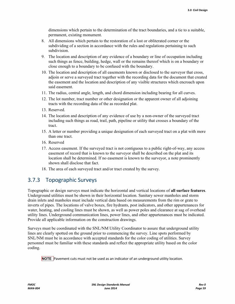
3.0 Civil Design
FMOC SNL Design Standards Manual Rev 0MAN-004 June 2014 Page 59
dimensions which pertain to the determination of the tract boundaries, and a tie to a suitable, permanent, existing monument.
8. All dimensions which pertain to the restoration of a lost or obliterated corner or the subdividing of a section in accordance with the rules and regulations pertaining to such subdivision.
9. The location and description of any evidence of a boundary or line of occupation including such things as fence, building, hedge, wall or the remains thereof which is on a boundary or close enough to a boundary to be confused with the boundary.
10. The location and description of all easements known or disclosed to the surveyor that cross, adjoin or serve a surveyed tract together with the recording data for the document that created the easement and the location and description of any visible structures which encroach upon said easement.
11. The radius, central angle, length, and chord dimension including bearing for all curves.
12. The lot number, tract number or other designation or the apparent owner of all adjoining tracts with the recording data of the as recorded plat.
13. Reserved.
14. The location and description of any evidence of use by a non-owner of the surveyed tract including such things as road, trail, path, pipeline or utility that crosses a boundary of the tract.
15. A letter or number providing a unique designation of each surveyed tract on a plat with more than one tract.
16. Reserved
17. Access easement. If the surveyed tract is not contiguous to a public right-of-way, any access easement of record that is known to the surveyor shall be described on the plat and its location shall be determined. If no easement is known to the surveyor, a note prominently shown shall disclose that fact.
18. The area of each surveyed tract and/or tract created by the survey.
3.7.3 Topographic Surveys
Topographic or design surveys must indicate the horizontal and vertical locations of all surface features. Underground utilities must be shown in their horizontal location. Sanitary sewer manholes and storm drain inlets and manholes must include vertical data based on measurements from the rim or grate to inverts of pipes. The locations of valve boxes, fire hydrants, post indicators, and other appurtenances for water, heating, and cooling lines must be shown, as well as power poles and clearance at sag of overhead utility lines. Underground communication lines, power lines, and other appurtenances must be indicated. Provide all applicable information on the construction drawings.
Surveys must be coordinated with the SNL/NM Utility Coordinator to assure that underground utility lines are clearly spotted on the ground prior to commencing the survey. Line spots performed by SNL/NM must be in accordance with accepted standards for the color coding of utilities. Survey personnel must be familiar with these standards and reflect the appropriate utility based on the color coding.
NOTE Pavement cuts must not be used as an indicator of an underground utility location.
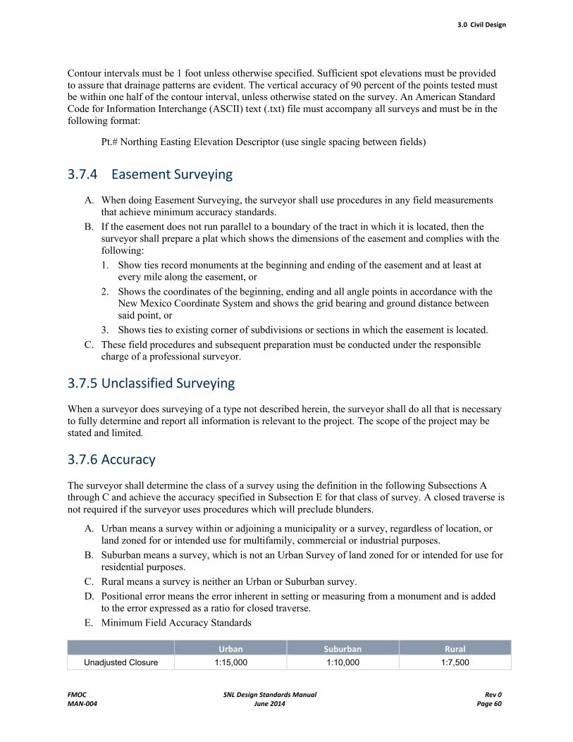
3.0 Civil Design
FMOC SNL Design Standards Manual Rev 0MAN-004 June 2014 Page 60
Contour intervals must be 1 foot unless otherwise specified. Sufficient spot elevations must be provided to assure that drainage patterns are evident. The vertical accuracy of 90 percent of the points tested must be within one half of the contour interval, unless otherwise stated on the survey. An American Standard Code for Information Interchange (ASCII) text (.txt) file must accompany all surveys and must be in the following format:
Pt.# Northing Easting Elevation Descriptor (use single spacing between fields)
3.7.4 Easement Surveying
A. When doing Easement Surveying, the surveyor shall use procedures in any field measurements that achieve minimum accuracy standards.
B. If the easement does not run parallel to a boundary of the tract in which it is located, then the surveyor shall prepare a plat which shows the dimensions of the easement and complies with the following:
1. Show ties record monuments at the beginning and ending of the easement and at least at every mile along the easement, or
2. Shows the coordinates of the beginning, ending and all angle points in accordance with the New Mexico Coordinate System and shows the grid bearing and ground distance between said point, or
3. Shows ties to existing corner of subdivisions or sections in which the easement is located.
C. These field procedures and subsequent preparation must be conducted under the responsible charge of a professional surveyor.
3.7.5 Unclassified Surveying
When a surveyor does surveying of a type not described herein, the surveyor shall do all that is necessary to fully determine and report all information is relevant to the project. The scope of the project may be stated and limited.
3.7.6 Accuracy
The surveyor shall determine the class of a survey using the definition in the following Subsections A through C and achieve the accuracy specified in Subsection E for that class of survey. A closed traverse is not required if the surveyor uses procedures which will preclude blunders.
A. Urban means a survey within or adjoining a municipality or a survey, regardless of location, or land zoned for or intended use for multifamily, commercial or industrial purposes.
B. Suburban means a survey, which is not an Urban Survey of land zoned for or intended for use for residential purposes.
C. Rural means a survey is neither an Urban or Suburban survey.
D. Positional error means the error inherent in setting or measuring from a monument and is added to the error expressed as a ratio for closed traverse.
E. Minimum Field Accuracy Standards
Urban Suburban Rural
Unadjusted Closure 1:15,000 1:10,000 1:7,500
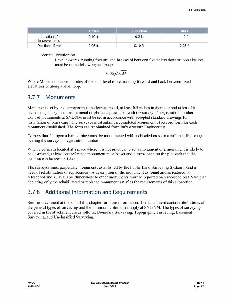
3.0 Civil Design
FMOC SNL Design Standards Manual Rev 0MAN-004 June 2014 Page 61
Urban Suburban Rural
Location of Improvements
0.10 ft. 0.2 ft. 1.0 ft.
Positional Error 0.05 ft. 0.10 ft. 0.25 ft.
Vertical PositioningLevel closures, running forward and backward between fixed elevations or loop closures, must be to the following accuracy:
Mft.05.0
Where M is the distance in miles of the total level route, running forward and back between fixed elevations or along a level loop.
3.7.7 Monuments
Monuments set by the surveyor must be ferrous metal, at least 0.5 inches in diameter and at least 16 inches long. They must bear a metal or plastic cap stamped with the surveyor's registration number. Control monuments at SNL/NM must be set in accordance with accepted standard drawings for installation of brass caps. The surveyor must submit a completed Monument of Record form for each monument established. The form can be obtained from Infrastructure Engineering.
Corners that fall upon a hard surface must be monumented with a chiseled cross or a nail in a disk or tag bearing the surveyor's registration number.
When a corner is located at a place where it is not practical to set a monument or a monument is likely to be destroyed, at least one reference monument must be set and dimensioned on the plat such that the location can be reestablished.
The surveyor must perpetuate monuments established by the Public Land Surveying System found in need of rehabilitation or replacement. A description of the monument as found and as restored or referenced and all available dimensions to other monuments must be reported on a recorded plat. Said plat depicting only the rehabilitated or replaced monument satisfies the requirements of this subsection.
3.7.8 Additional Information and Requirements
See the attachment at the end of this chapter for more information. The attachment contains definitions of the general types of surveying and the minimum criteria that apply at SNL/NM. The types of surveying covered in the attachment are as follows: Boundary Surveying, Topographic Surveying, Easement Surveying, and Unclassified Surveying.
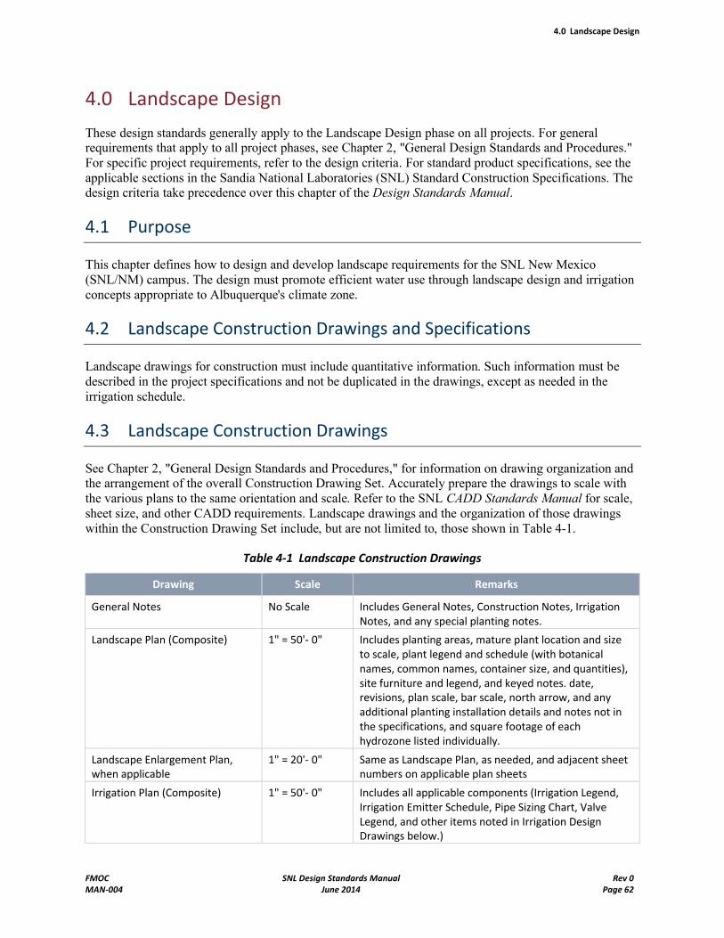
4.0 Landscape Design
FMOC SNL Design Standards Manual Rev 0MAN-004 June 2014 Page 62
4.0 Landscape Design
These design standards generally apply to the Landscape Design phase on all projects. For general requirements that apply to all project phases, see Chapter 2, "General Design Standards and Procedures." For specific project requirements, refer to the design criteria. For standard product specifications, see the applicable sections in the Sandia National Laboratories (SNL) Standard Construction Specifications. The design criteria take precedence over this chapter of the Design Standards Manual.
4.1 Purpose
This chapter defines how to design and develop landscape requirements for the SNL New Mexico (SNL/NM) campus. The design must promote efficient water use through landscape design and irrigation concepts appropriate to Albuquerque's climate zone.
4.2 Landscape Construction Drawings and Specifications
Landscape drawings for construction must include quantitative information. Such information must be described in the project specifications and not be duplicated in the drawings, except as needed in the irrigation schedule.
4.3 Landscape Construction Drawings
See Chapter 2, "General Design Standards and Procedures," for information on drawing organization and the arrangement of the overall Construction Drawing Set. Accurately prepare the drawings to scale with the various plans to the same orientation and scale. Refer to the SNL CADD Standards Manual for scale, sheet size, and other CADD requirements. Landscape drawings and the organization of those drawings within the Construction Drawing Set include, but are not limited to, those shown in Table 4-1.
Table 4-1 Landscape Construction Drawings
Drawing Scale Remarks
General Notes No Scale Includes General Notes, Construction Notes, Irrigation Notes, and any special planting notes.
Landscape Plan (Composite) 1" = 50'- 0" Includes planting areas, mature plant location and size to scale, plant legend and schedule (with botanical names, common names, container size, and quantities), site furniture and legend, and keyed notes. date, revisions, plan scale, bar scale, north arrow, and any additional planting installation details and notes not in the specifications, and square footage of each hydrozone listed individually.
Landscape Enlargement Plan, when applicable
1" = 20'- 0" Same as Landscape Plan, as needed, and adjacent sheet numbers on applicable plan sheets
Irrigation Plan (Composite) 1" = 50'- 0" Includes all applicable components (Irrigation Legend, Irrigation Emitter Schedule, Pipe Sizing Chart, Valve Legend, and other items noted in Irrigation Design Drawings below.)
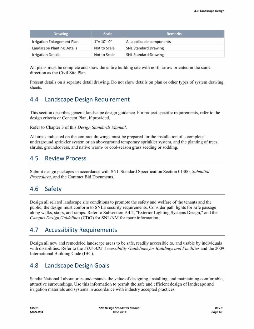
4.0 Landscape Design
FMOC SNL Design Standards Manual Rev 0MAN-004 June 2014 Page 63
Drawing Scale Remarks
Irrigation Enlargement Plan 1"= 10'- 0" All applicable components
Landscape Planting Details Not to Scale SNL Standard Drawing
Irrigation Details Not to Scale SNL Standard Drawing
All plans must be complete and show the entire building site with north arrow oriented in the same direction as the Civil Site Plan.
Present details on a separate detail drawing. Do not show details on plan or other types of system drawing sheets.
4.4 Landscape Design Requirement
This section describes general landscape design guidance. For project-specific requirements, refer to the design criteria or Concept Plan, if provided.
Refer to Chapter 3 of this Design Standards Manual.
All areas indicated on the contract drawings must be prepared for the installation of a complete underground sprinkler system or an aboveground temporary sprinkler system, and the planting of trees, shrubs, groundcovers, and native warm- or cool-season grass seeding or sodding.
4.5 Review Process
Submit design packages in accordance with SNL Standard Specification Section 01300, Submittal Procedures, and the Contract Bid Documents.
4.6 Safety
Design all related landscape site conditions to promote the safety and welfare of the tenants and the public; the design must conform to SNL's security requirements. Consider path lights for safe passage along walks, stairs, and ramps. Refer to Subsection 9.4.2, "Exterior Lighting Systems Design," and the Campus Design Guidelines (CDG) for SNL/NM for more information.
4.7 Accessibility Requirements
Design all new and remodeled landscape areas to be safe, readily accessible to, and usable by individuals with disabilities. Refer to the ADA-ABA Accessibility Guidelines for Buildings and Facilities and the 2009 International Building Code (IBC).
4.8 Landscape Design Goals
Sandia National Laboratories understands the value of designing, installing, and maintaining comfortable, attractive surroundings. Use this information to permit the safe and efficient design of landscape and irrigation materials and systems in accordance with industry accepted practices.
4.0 Landscape Design
FMOC SNL Design Standards Manual Rev 0MAN-004 June 2014 Page 64
The practice of landscape architecture and construction varies considerably depending on the geographic location, soil characteristics, and microclimate of a given area.
Sandia National Laboratories wants to create and maintain a campus-like atmosphere through the landscape surrounding its buildings and infrastructure. Landscape development should enhance the overall exterior appearance of buildings and related sites while serving as a link connecting buildings, pathways, and the various outdoors spaces of the SNL/NM campus. To achieve this campus atmosphere SNL is providing these design guidelines. The SNL Master Landscape Plan (Draft) has more information on goals and principles for exterior design at SNL, which must be understood and followed. These design guidelines should be used with the latest version of the Campus Design Guidelines
Design landscape improvements in accordance with the design criteria or Concept Plan (if provided) and the Campus Design Guidelines.
Landscape irrigation and water conservation are long-term requirements at SNL and provide a positive measure of efficiency in their actual performance when measured over time. Emphasize xeriscape principles to minimize maintenance and promote low water usage. This effort can be effective by using a variety of native plant material and grasses. Do not simply avoid the use of canopy shade trees. Shade trees can cool environments and make pedestrian areas more usable. Similarly, certain entry courts and the north sides of multistory buildings lend themselves to an oasis or high-mountain type of design that might not be xeric.
Capture storm water from roofs in storage tanks and site water infiltrated into the ground as assets to reduce site drainage runoff and storm drain costs and liabilities.
Consider landscaping when designing energy-conservation solutions. Landscaping design should reduce solar radiation during the growing season (summer) and heat loss from winter winds.
4.9 Existing Condition
Evaluate the project site and prepare plans showing all landscape features, including plant material and irrigation heads. Have department 4843, Grounds & Road Services (G&RS), activate the irrigation system to determine its operability. As a minimum, the design team, the G&RS Supervisor, and the SNL Landscape Architect/Site Horticulturalist, must use the geographical information system (GIS) maps during a site visit to verify the accuracy of information. Collect critical measurements during site visits. Existing drawings may be obtained from the SNL CADD Department (4825). The SNL Landscape Architect/Site Horticulturalist also has some hard copies of existing drawings.
Identify affected areas and potential areas lying outside the limits of construction, such as laydown areas, that might be affected and might need to be restored or revegetated as part of the construction.
Provide additional utility-location methods, such as line spotting, potholing, and excavation, as required to design the project properly. Refer to Chapter 3, "Civil Design," for more information.
Before designing any landscape or irrigation construction or renovation project, contact the SNL Staff Biologist for guidance about special provisions necessary to protect or minimize areas of expansion of wildlife, such as burrowing owls, migratory birds, and prairie dogs.
Contact the Staff Biologist at the following address:
Sandia National Laboratories Staff BiologistEnvironmental Programs Department
4.0 Landscape Design
FMOC SNL Design Standards Manual Rev 0MAN-004 June 2014 Page 65
Organization # 4143P.O. Box 5800, MS 730505-845-7711
4.10 Landscape Design Considerations
Plan and apply xeriscape design principles. These principles promote the use of native, well-adapted plant material and reduce maintenance and irrigation requirements. Consider landscape design concepts that incorporate functional water and energy conservation methods. Xeriscape installations can effectively address the valuable water resource proficiently and economically. In the larger design framework, uselow-impact design and development principles. See the Master Landscape Plan for more information.Consider the following areas:
Develop a Plan: Plan the landscape with regard for function, image, and quality. Evaluation factors must include the following:
Existing Conditions (preserve mature trees)
Views (enhance positive views)
Vehicular and Pedestrian Circulation (address safety and logical paths and clear visibility for pedestrians)
Quality of user experience (improve shading, cooling effects of canopy trees, wind-reduction opportunities)
Topography (stabilize steep slopes)
Soils (test soil to confirm suitable pH, electrical conductivity or EC, texture, exchangeable sodium percentage or ECP, and calcium carbonate or CaCO3. Also, recommend the addition of amendments to adjust for soil test deficiencies.)
Utilities (avoid underground utility locations)
Water Supply (employ existing piped or harvested and reclaimed water sources as part of the project)
Drainage (integrate run-off patterns, locate potential ponding areas, and incorporate into planting plans where feasible)
Security Requirements (observe line-of-sight and required setbacks)
Wildlife (preserve existing habitat and limit the growth of habitat)
Minimize Cool Season Turf Areas: Cool season sodded turf is discouraged at SNL and must only be added or replaced in areas where cool season sodded turf is desirable. Consider the use of warm season sodding or seeding.
Improve Soils: Soils can vary greatly over an installation or even over a job site. A soils analysis determines exactly what improvements might be required. Soils at SNL tend to be very compacted after construction, and ripping and loosening the soil is a significant need and should be considered a requirement unless otherwise noted.
Test Soils: Collect samples of soil in planting and seeding areas. Mix and submit a single composite sample to a recognized testing laboratory for evaluation of fertility. Testing must evaluate pH, base saturation percentage, ECP, EC, texture, and free lime. Sample turf and planting beds separately.
4.0 Landscape Design
FMOC SNL Design Standards Manual Rev 0MAN-004 June 2014 Page 66
Conserve Natural Resources: Conservation and protection of the natural resources at the site are important. Keep any disturbance of natural resources occurring during planting operations to a minimum. Consider harvesting existing plants and relocating them to other sites or containerizing and storing them for reuse on the site.
Select Water-Efficient Plants: Use water-efficient plants in appropriate settings. Less xeric plants may be used in oasis areas or in pedestrian or parking lot applications. Plants that require less water are readily available locally and in surrounding regions and states. Consider the use of rabbit- and prairie-dog resistant plant material.
Use Mulches Appropriately: Mulching with open voids (materials with no fines) provides protection and cover around plant material, reduces evaporation, reduces runoff, increases infiltration, cools soil temperatures, and reduces erosion. Crusher fines are not considered to provide these benefits. Trees not located within hardscape plantings (for example, within turf, dirt, or rock mulch areas) must be designed with wood mulch ring bases 4 times the diameter of the root ball to be planted.
Consider Storm Water Pollution Prevention Plans (SWPPPs): To allow SWPPPs to be closed by the end of a given project design, remnant dirt areas must be drill-seeded with native grasses, wildflowers, or both, and covered with a minimal layer of rock mulch. A temporary irrigation system must be installed to support the grasses and wildflowers until they are established with a minimal layer of rock mulch (not more than 2 inches).
Design for Maintenance: The design must aid in determining the required maintenance. Designing "smart" allows SNL to manage effectively and maintain its landscaping while using resources efficiently.
Consider Plant Placement Carefully: The placement of trees and shrubs in turf areas should be done with careful consideration of species, mature size, rooting habits and depths, and water requirements.
When trees are placed they must be mulched according to the guidelines provided above in "Use MulchesAppropriately." Do not locate shrubs in turf areas. Locate shrubs so the mature size footprint they produce does not extend into pedestrian or vehicle pathways or interfere with the site triangle/distance at roadway intersections or driveways.
Carefully consider the placement of trees in relation to facility structures and utilities. Undergroundutilities must be avoided by a minimum of 5 feet in any direction. In case of conflicts with utilities,contact the appropriate Systems Engineer to determine the correct setback of trees and shrubs from the utility in question. When considering planting trees in proximity to gas or sewer lines, plastic or herbicide impregnated root barriers must be considered and used where deemed necessary by the System Engineer.
Because of security issues and plant competition for water, shrub placement together with trees in parking lot islands is to be reviewed with the SNL Landscape Architect/Site Horticulturalist or the Grounds and Road Services Supervisor.
Canopy shade trees should be set back 5 feet from any paving, curb, or fixed object. Further, keep larger canopy trees 20 feet from any building edge. Smaller ornamental trees can be 10 to 15 feet from a structure and 5 feet from paving edges. Coordinate placement of canopy shade trees with roadway or pedestrian path lighting.
Design all landscapes so they do not impede visual assessment or allow bridging of any security fence. Specifically, no landscape plants or boulders must be installed within 10 feet of any security fence. See the Campus Design Guidelines for more information.
Use curbs or seat walls for shrub beds to reduce sand and trash from being blown into shrub beds.
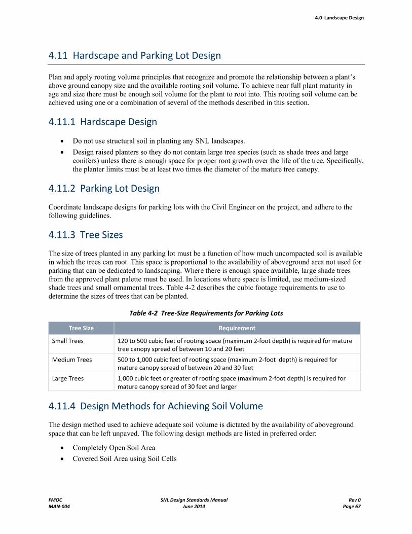
4.0 Landscape Design
FMOC SNL Design Standards Manual Rev 0MAN-004 June 2014 Page 67
4.11 Hardscape and Parking Lot Design
Plan and apply rooting volume principles that recognize and promote the relationship between a plant’s above ground canopy size and the available rooting soil volume. To achieve near full plant maturity in age and size there must be enough soil volume for the plant to root into. This rooting soil volume can be achieved using one or a combination of several of the methods described in this section.
4.11.1 Hardscape Design
Do not use structural soil in planting any SNL landscapes.
Design raised planters so they do not contain large tree species (such as shade trees and large conifers) unless there is enough space for proper root growth over the life of the tree. Specifically, the planter limits must be at least two times the diameter of the mature tree canopy.
4.11.2 Parking Lot Design
Coordinate landscape designs for parking lots with the Civil Engineer on the project, and adhere to the following guidelines.
4.11.3 Tree Sizes
The size of trees planted in any parking lot must be a function of how much uncompacted soil is available in which the trees can root. This space is proportional to the availability of aboveground area not used for parking that can be dedicated to landscaping. Where there is enough space available, large shade trees from the approved plant palette must be used. In locations where space is limited, use medium-sizedshade trees and small ornamental trees. Table 4-2 describes the cubic footage requirements to use to determine the sizes of trees that can be planted.
Table 4-2 Tree-Size Requirements for Parking Lots
Tree Size Requirement
Small Trees 120 to 500 cubic feet of rooting space (maximum 2-foot depth) is required for mature tree canopy spread of between 10 and 20 feet
Medium Trees 500 to 1,000 cubic feet of rooting space (maximum 2-foot depth) is required for mature canopy spread of between 20 and 30 feet
Large Trees 1,000 cubic feet or greater of rooting space (maximum 2-foot depth) is required for mature canopy spread of 30 feet and larger
4.11.4 Design Methods for Achieving Soil Volume
The design method used to achieve adequate soil volume is dictated by the availability of aboveground space that can be left unpaved. The following design methods are listed in preferred order:
Completely Open Soil Area
Covered Soil Area using Soil Cells

4.0 Landscape Design
FMOC SNL Design Standards Manual Rev 0MAN-004 June 2014 Page 68
4.11.5 Other Hardscape Tree Planting Designs
Coordinate landscape designs for pedestrian areas with the Civil Engineer on the project, and adhere to the guidelines listed below.
Designing tree and shrub plantings for pedestrian areas is dependent on the sidewalk width and the amount of space between permanent structures, such as buildings and utilities. Reference the Tree Space Design Matrix on page 9 of the Tree Space Design publication entitled "Growing the Trees Out of the Box," published by [email protected]. With this matrix use the following design methods:
Completely Open Soil Area
Covered Soil Area using Soil Cells
Covered Soil Area Connected to Green Space
Open Soil Connected to Green Space
4.11.6 Rain Water Harvesting
Use rainwater harvesting and retention. When possible, incorporate rainwater harvesting into parking lot design. Both passive and active systems may be designed. Promote a design that manages and integratesthe use of storm water into the landscape. Sandia National Laboratories encourages the capture of roof water, which is typically comparatively clean and disposed of at a single or few locations in a cistern. All rainwater harvesting designs must be done in accordance with the Grading and Drainage Plan and in accordance with SNL policy for the retention and detention of developed storm water flows.
Note that swales are used and function to evacuate and drain water. They can also lower adjacent water moisture. Swales are not a water conservation element by design. Providing small check dams, unpaved areas with minimum acceptable slopes or gradients, and shallow water ponding areas with flat bottoms coordinated with tree locations is encouraged. Reduce or eliminate site runoff, and use the rainfall for trees and shrubs.
Include a grading plan design indicating finished configurations and elevations of the landscape areas, including the height of graded slopes, impoundment areas, ponds, water-recharge zones, percent of slopes, general drainage patterns, pad elevations, and finished grade. Design grading and drainage to create onsite water harvesting wherever possible.
Any rainwater harvesting system that captures and stores water for release under pressure must be designed so that it is integrated into the Centralized Irrigation Control System (CICS) and uses a CICS-compatible flow meter.
4.12 Damage Control and Mitigation
Effective tree and landscape feature preservation must be integrated with the project design and site development. Formulate a plan to identify, limit, and remediate damage to the landscape relative to the proposed project site and its adjacencies by addressing the following Table 4-3 requirements:
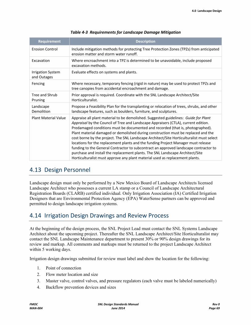
4.0 Landscape Design
FMOC SNL Design Standards Manual Rev 0MAN-004 June 2014 Page 69
Table 4-3 Requirements for Landscape Damage Mitigation
Requirement Description
Erosion Control Include mitigation methods for protecting Tree Protection Zones (TPZs) from anticipated erosion matter and storm water runoff.
Excavation Where encroachment into a TPZ is determined to be unavoidable, include proposed excavation methods.
Irrigation System and Outages
Evaluate effects on systems and plants.
Fencing Where necessary, temporary fencing (rigid in nature) may be used to protect TPZs and tree canopies from accidental encroachment and damage.
Tree and Shrub Pruning
Prior approval is required. Coordinate with the SNL Landscape Architect/Site Horticulturalist.
Landscape Demolition
Propose a Feasibility Plan for the transplanting or relocation of trees, shrubs, and other landscape features, such as boulders, furniture, and sculptures.
Plant Material Value Appraise all plant material to be demolished. Suggested guidelines: Guide for Plant Appraisal by the Council of Tree and Landscape Appraisers (CTLA), current edition. Predamaged conditions must be documented and recorded (that is, photographed). Plant material damaged or demolished during construction must be replaced and the cost borne by the project. The SNL Landscape Architect/Site Horticulturalist must select locations for the replacement plants and the funding Project Manager must release funding to the General Contractor to subcontract an approved landscape contractor to purchase and install the replacement plants. The SNL Landscape Architect/Site Horticulturalist must approve any plant material used as replacement plants.
4.13 Design Personnel
Landscape design must only be performed by a New Mexico Board of Landscape Architects licensed Landscape Architect who possesses a current LA stamp or a Council of Landscape Architectural Registration Boards (CLARB) certified individual. Only Irrigation Association (IA) Certified Irrigation Designers that are Environmental Protection Agency (EPA) WaterSense partners can be approved and permitted to design landscape irrigation systems.
4.14 Irrigation Design Drawings and Review Process
At the beginning of the design process, the SNL Project Lead must contact the SNL Systems Landscape Architect about the upcoming project. Thereafter the SNL Landscape Architect/Site Horticulturalist may contact the SNL Landscape Maintenance department to present 30% or 90% design drawings for itsreview and markup. All comments and markups must be returned to the project Landscape Architect within 5 working days.
Irrigation design drawings submitted for review must label and show the location for the following:
1. Point of connection
2. Flow meter location and size
3. Master valve, control valves, and pressure regulators (each valve must be labeled numerically)
4. Backflow prevention devices and sizes
4.0 Landscape Design
FMOC SNL Design Standards Manual Rev 0MAN-004 June 2014 Page 70
5. Mainline and lateral piping sizes
6. Isolation valves and quick coupler valves
7. Manual drain valves
8. Hose bibs and hydrants
9. Sprinklers, bubblers, drip emitters, filters, control wire routing and sizes, and controller
10. Power supply/electrical access
11. Date, revisions, legend, and scale
12. Irrigation installation details, notes, and specifications
13. Designer's name, address, telephone number, and certification or license number
In addition to the information listed above, Irrigation Plans must have a System Performance Information Chart in Microsoft Excel that gives the following information for each control valve:
1. Control valve number
2. Valve manufacturer, model number, and size
3. Irrigation head manufacturer and model number
4. Irrigation head nozzle size
5. Irrigation head radius and spacing
6. Irrigation head gallons per minute and per hour
7. Total gallons per minute/valve
8. Design operating pressure through the valve and at the head
9. Precipitation rate at the design operating pressure
10. Length of time required to operate the valve to apply .25 inches of water
On Leadership in Energy and Environmental Design (LEED)-rated projects, submit a water budget showing required reductions in water use from the baseline. Use the Blaney-Criddle formula for evapotranspiration (Et) rates.
All irrigation plans must state the existing static pressure at the meter or point of connection.
The following statement must appear on the face of each irrigation plan: At the time of final acceptance, the Contractor must demonstrate to the SNL Landscape Architect/Site Horticulturalist that the operating pressure at the head has been adjusted to match the specified design operating pressure for each valve.
4.15 Distribution Uniformity
Design and install each system such that its performance enhances distribution and emission uniformity and promotes the efficient use and protection of SNL water resources.
Conduct a distribution uniformity (DU) test using established IA landscape water-auditing guidelines using catch can tests that measure the actual amount of water applied to the target landscape on all irrigation system installations.
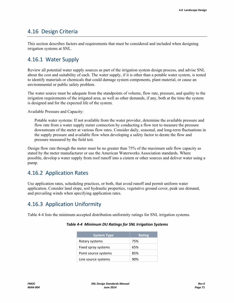
4.0 Landscape Design
FMOC SNL Design Standards Manual Rev 0MAN-004 June 2014 Page 71
4.16 Design Criteria
This section describes factors and requirements that must be considered and included when designing irrigation systems at SNL.
4.16.1 Water Supply
Review all potential water supply sources as part of the irrigation system design process, and advise SNL about the cost and suitability of each. The water supply, if it is other than a potable water system, is tested to identify materials or chemicals that could damage system components, plant material, or cause an environmental or public safety problem.
The water source must be adequate from the standpoints of volume, flow rate, pressure, and quality to the irrigation requirements of the irrigated area, as well as other demands, if any, both at the time the system is designed and for the expected life of the system.
Available Pressure and Capacity:
Potable water systems: If not available from the water provider, determine the available pressure and flow rate from a water supply meter connection by conducting a flow test to measure the pressure downstream of the meter at various flow rates. Consider daily, seasonal, and long-term fluctuations in the supply pressure and available flow when developing a safety factor to derate the flow and pressure measured by the field test.
Design flow rate through the meter must be no greater than 75% of the maximum safe flow capacity as stated by the meter manufacturer or use the American Waterworks Association standards. Where possible, develop a water supply from roof runoff into a cistern or other sources and deliver water using a pump.
4.16.2 Application Rates
Use application rates, scheduling practices, or both, that avoid runoff and permit uniform water application. Consider land slope, soil hydraulic properties, vegetative ground cover, peak use demand, and prevailing winds when specifying application rates.
4.16.3 Application Uniformity
Table 4-4 lists the minimum accepted distribution uniformity ratings for SNL irrigation systems.
Table 4-4 Minimum DU Ratings for SNL Irrigation Systems
System Type Rating
Rotary systems 75%
Fixed spray systems 65%
Point source systems 85%
Line source systems 90%
4.0 Landscape Design
FMOC SNL Design Standards Manual Rev 0MAN-004 June 2014 Page 72
The SNL Landscape Architect/Site Horticulturalist must commission the irrigation system as a whole. The commissioning must include an irrigation system audit with at least one representative valve (as recognized by IA nomenclature) from each zone type installed (drip, bubbler, fixed spray, or rotor) being audited and passing the minimum DU requirements listed above. Any zone not meeting the minimum target values must be redesigned, reconstructed, or both, until it meets the minimum target values. All zones of the same type that use the same emission devices (drip, bubbler, fixed spray, or rotor) as the failed zone must be audited and be required to meet the minimum DU values in Table 4-4.
4.16.4 Peak Water Use Requirements
The irrigation system must be capable of meeting the peak water use demand of turf and landscape areas. Estimate the peak water use requirement based on the plant species and local climate conditions. If using a cistern, estimate year-round flows. Any overhead spray irrigation system must have the capacity to apply water at a rate that satisfies the peak water demand of the fully mature landscape within 12 hours. If line size is a limiting factor, it must be addressed during the design phase.
4.16.5 System Zoning
Divide the irrigation system into zones based on the following considerations:
Available flow rate, water velocity, and pressure
Consistency with hydrozone concepts
Sprinkler heads with matched precipitation rates
Type of vegetation irrigated (such as turf, trees, or shrubs)
Consistency with microclimates (such as buildings, shaded areas, and reflective heat)
Elimination of mixed head types (such as bubblers and rotaries on the same zone)
Cultural use of the area (such as pedestrian walks and seating areas)
4.17 Irrigation System Source
The preferred source for landscape irrigation water is from building potable water systems. Coordinate with the Mechanical Designer for location and correct pressure of irrigation water needed for landscaping. Evaluation of alternate sources (harvested rainfall, cisterns, and so on) is encouraged. If alternate sources are used, include in the water budget if a LEED-rated project.
4.18 Irrigation Equipment Selection – General
Select equipment consistent with SNL's landscape requirements and central irrigation control system (CICS). Adjustments to manufacturer's altitude rating are required for SNL/NM altitude at 5,000 feet.
Select equipment, when available, that is labeled WaterSense by the EPA. The project Landscape Architect must consult the EPA WaterSense website to look for products that are labeled WaterSense.
Design sprinkler and bubbler irrigation systems to meet water requirements for individual plants at maturity.
4.0 Landscape Design
FMOC SNL Design Standards Manual Rev 0MAN-004 June 2014 Page 73
4.18.1 Controller
Select a controller capable of handling the required zones with a minimum of two additional spare zones. See the SNL Standard Specification 02812, Landscape Irrigation Systems.
Design as recommended in the Calsense Designers Guide available from Calsense, Inc. at (800) 573-8608 or locally from Ewing Irrigation at (505) 821-4441.
Ensure the irrigation system design incorporates CICS either with a new controller and flow meter installation or by using an existing controller and "tying" the new system into the existing one.
Projects that include construction of a new building must specify that the Calsense controller communicate using internal Ethernet modem back to central. The Calsense controller must be specified in the following manner: ET2000E - # of stations desired – EN – RRe – F.
4.18.2 Controller Enclosure
The preferred enclosure for the Calsense controller is the pedestal-mount heavy-duty stainless steel enclosure. When this option is not possible, installing the standard wall mount enclosure is acceptable.
4.18.3 Wiring
Refer to Standard Drawing LP5002, "Irrigation Details."
Show wire route and size on plan.
Install one extra wire to each valve in the same trench as the other zone wires.
4.18.4 Backflow Preventers
Backflow-preventers (BFPs) must be approved by SNL. Refer to Section 7.3, "Fire Protection Backflow Preventers," in this Design Standards Manual. Apply the devices in accordance with the City of Albuquerque Cross Connection Control Ordinance, Section 8.6.6 of this manual, and the following guidelines:
Double-check assemblies are not permitted for use on irrigation systems.
Wilkins backflow preventers must be specified. Pressure gauges with isolation valves should be installed in the inlet and outlet piping to the backflow preventer.
Backflow preventers may be installed in building's mechanical room.
4.18.5 Backflow Prevention Assembly Freeze Protection
The approved backflow prevention assembly enclosure must be a positively heated insulated enclosure.
If positive heat is not available, an approved Lexan enclosure may be used. Submittals must be provided through the usual channels for use of a Lexan enclosure.
4.0 Landscape Design
FMOC SNL Design Standards Manual Rev 0MAN-004 June 2014 Page 74
4.18.6 Pressure Regulating Valves
Provide an adjustable brass pressure-regulating valve (PRV) on all projects downstream of the point of connection and upstream of the backflow preventer. The PRV can be located in any position (for example, horizontal or vertical). Individual pressure regulators must be used on zones requiring low pressure (drip or low-flow bubblers).
4.18.7 Flow Meter
Flow meters must be used in all irrigation applications using the CICS. Consult with the SNL Landscape Architect/Site Horticulturalist about the use of a flow meter on any given irrigation system. This consultation must occur regardless of the water sourcepotable or nonpotable.
4.18.8 Master Valves
Normally closed master valves must be used on all irrigation systems.
4.18.9 Quick Coupler Valves
Quick-coupler valves must be installed as needed or a minimum of every 100 feet of mainline as per SNL Detail Drawing LP5002STD.DGN #14.
4.18.10 Drain Valves
Automatic drain valves are not acceptable. Use one manual drain valve in the low point of each lateral and mainline piping.
4.18.11 Piping
Construction Standard Specification 02812, Irrigation Systems, specifies materials, processes, and installation requirements for subgrade irrigation systems that apply as designated on the contract drawings.
All pipelines must be sized and routed to limit pressure variations, so the operating pressure at all points in the irrigation system is in the range required by the manufacturer for uniform water application.
As a safety factor against surge or water hammer, the working pressure must not exceed 72% of the pressure rating of the pipe with the pipeline water velocity limited to 5 feet per second.
Design the system with the appropriate size pipe to limit variations in operating pressure between the first and last emission devices (sprinklers, bubblers, drip) on a given zone to 20% or less.
4.18.12 Fittings
Male adapters must not be used to connect valves; use toe nipples instead.
4.0 Landscape Design
FMOC SNL Design Standards Manual Rev 0MAN-004 June 2014 Page 75
4.18.13 Multioutlet, Point Source, and Line Emitters, and Bubblers
As a general rule, all plant material must be designed using a multioutlet point source (MOED) emitter system. Only dense planting beds must be designed using a line source emitter system.
All trees and shrubs must be designed with drip/micro irrigation systems unless specified otherwise. The drip system for trees must use two ball valves to divide the system into sectionsone for the first 1 to 5 years of establishment and the second for 6 years and older of maturity. Reference Irrigation Detail Drawing LP5002STD.DGN #13.
Use pressure-compensating emission devices only in instances where elevation changes warrant them.
The location of drip emitters or bubblers is important in proper water distribution and in allowing the plant to mature fully. Evenly distribute emitters around the root ball at least 12 inches from the outside edge of the root ball.
Account for differences in plant Et rates by using different nozzle size emitters or using greater or fewer emitter numbers.
Group plants on a given zone according to type, size, and Et rates, for example, trees and shrubs should not be placed on the same valve.
4.18.14 Spray Heads
Design all spray head irrigation systems using Matched Precipitation Rate principles.
In turf areas, use a triangular-spaced spray head system when possible.
All fixed-spray sprinkler systems must be designed using in-head check valves and in-head pressure regulators.
All fixed-spray and bubbler irrigation systems must be designed with pressure-compensating devices.
Do not use spray irrigation heads when designing for areas less than 10 feet in any direction.
Space sprinklers to prevent overspray onto adjacent property, nonirrigated areas, walks, roadways, or structures. Heads must be located 8 inches from any hard surface.
Use a minimum 4-inch pop-up fixed spray head in all cool season turf areas. Use a minimum 6-inch pop-up fixed-spray head in all native or warm season turf areas.
Specify fixed-spray heads that have fixed-arc nozzles whenever possible. Adjustable-arc nozzles must be used only when odd arcs are required.
Provide fixed-spray heads connected to the same control valve with matched precipitation rates to guarantee application of water at the same rate.
Provide fixed spray heads with automatic flow shut-off devices in areas where damage from pedestrians or vehicles might occur.
4.0 Landscape Design
FMOC SNL Design Standards Manual Rev 0MAN-004 June 2014 Page 76
4.18.15 Rotary Sprinklers
Design all rotary spray head irrigation systems using Matched Precipitation Rate principles ensuring that the radius of throw is constant regardless of the arc.
Provide rotors that have the smallest practical radius to reduce wind drift.
Impact rotary heads are not acceptable for use.
A triangular-spaced spray head system is preferred for use in turf areas when possible.
All rotary-head sprinkler systems must be designed using in-head pressure regulators. In locations of changing elevations, the system must be designed using check valves at the base of each head to eliminate or reduce low-head drainage.
Locate rotor sprinklers 8 inches away from sidewalks, edges of paved areas, and adjacent walls, buildings or fences.
Use a minimum 4-inch pop-up rotary head in all cool season turf areas.
Use a minimum 12-inch pop-up rotary head in all warm season turf areas.
Provide rotors with automatic flow shut-off devices in areas where damage from pedestrians or vehicles may occur.
A triangular-spaced rotary head design must be applied to large turf areas where overthrow of the sprinklers is not a concern (no buildings or hard surfaces).
4.18.16 Miscellaneous Parts and Components
Refer to SNL Standard Specification Section 02812, Landscape Irrigation System, and Facilities Standard Drawings LP5001001STD and LP5001002STD for listing and additional irrigation equipment requirements. These requirements include the following:
Ball Valve
Electric Valve
Manual Drain Valve
4.19 Reclaimed Water Guidelines
When a project has reclaimed water available or is in an area that will have reclaimed water available as irrigation water, install the irrigation system using the industry standard purple color, pipes marked "Reclaimed Water – Do Not Drink," or both, valves boxes, and sprinkler heads.
Meter the backup potable water supply.
The backup supply water is only to be used in emergencies when reclaimed water is unavailable. Protect the backup water supply with the appropriate backflow prevention device. If a project is to be LEED-certified, include reclaimed water in the water budget.
Control valves using effluent water must not have an external manual bleed.
4.0 Landscape Design
FMOC SNL Design Standards Manual Rev 0MAN-004 June 2014 Page 77
4.20 Irrigation Scheduling
Proper irrigation scheduling applies the correct amount of water at the correct intervals for optimum growing conditions for plant material. A schedule must define the time of day, days of the week, and length of time a zone is operated to apply water.
Develop an irrigation schedule that accounts for the effects of temperature, plant species, soil types, precipitation rates, and microclimates. (Either the project Landscape Architect or Irrigation Designer develops this schedule.)
Base schedules must be developed for each zone/station/month for the first 12 months after installation. Use the following criteria to develop base schedules:
Runtimes per zone/station
Cycles per day
Days per week or frequency
Changes in irrigation frequency in response to changes in Et must be reflected by increasing or decreasing the frequencies rather than changing the length of the run time. These changes must be reflected on monthly schedules for an entire year.
When water application rates exceed soil infiltration rates, determine the run time before run-off occurs and incorporate this variable into the schedule.
The schedule must use the principles approved and used by the Irrigation Association in its Landscape Irrigation Auditor Program, and the LEED system, if applicable.
4.21 Schedules, Charts, and Legend
Schedules of equipment or plant material must be complete, well-organized, and representative of industry standards.
5.0 Structural Design
FMOC SNL Design Standards Manual Rev 0MAN-004 June 2014 Page 78
5.0 Structural Design
5.1 Introduction
The requirements of this Chapter apply to the structural phase of every applicable design project performed for Sandia National Laboratories New Mexico (SNL/NM).
The requirements of this Chapter apply to nuclear and non-nuclear facilities that have a Performance Category of PC-1 to PC-4 as determined by DOE-STD-1021-93. For all nuclear facilities and for all non-nuclear facilities of PC-3 or PC-4, this Chapter shall be supplemented with the requirements of an applicable project specific Design Criteria. Information contained in a project specific Design Criteria shall take precedence over the design requirements of this Chapter.
For all general requirements associated with the design phase of a project, see Chapter 2, General Design Standards and Procedures.
For all product specifications, see the Facilities Construction Standard Specifications.
5.2 Design Requirements
5.2.1 General
The following is an outline summary of the general structural requirements that the Engineer of Record (EOR) shall consider for each project design. At design completion, the EOR shall use two methods to document all applicable structural design information. The first method is to submit to SNL/NM the information required in Section 5.2.9 of this Chapter. The second method is to record the information on the General Structural Notes sheet of the project's construction drawings, which shall include the following details:
Brief narrative description of the building's substructure and superstructure
Brief narrative of all special structural features
Codes and Manuals used for design and construction
Building Type of Construction
Building Performance Category per DOE-STD-1021-93
Design loading criteria with detailed coefficients and factors
Geotechnical Report reference
Brief narrative of key geotechnical information used for design and construction
Outline specifications of construction materials and methods
Statement of Special Inspections required to verify construction complies with design
List of all mechanical/electrical/other equipment that has been seismically protected
Fall protection structural information
Identify load capacities for all conveying systems such as elevators, cranes, and hoists.
Schedules, Tables, Diagrams that enhance the presentation of the scope of work
List of computer files used for design, including archive location information
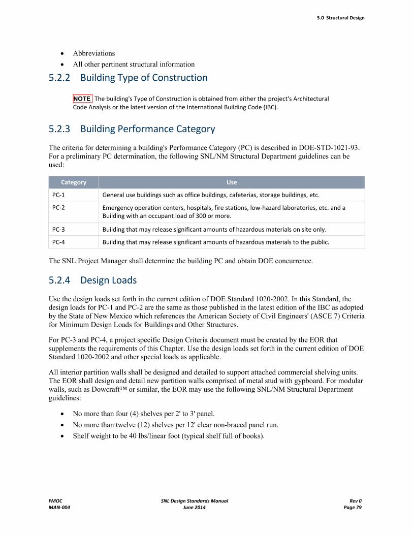
5.0 Structural Design
FMOC SNL Design Standards Manual Rev 0MAN-004 June 2014 Page 79
Abbreviations
All other pertinent structural information
5.2.2 Building Type of Construction
NOTE The building's Type of Construction is obtained from either the project's Architectural Code Analysis or the latest version of the International Building Code (IBC).
5.2.3 Building Performance Category
The criteria for determining a building's Performance Category (PC) is described in DOE-STD-1021-93. For a preliminary PC determination, the following SNL/NM Structural Department guidelines can be used:
Category Use
PC-1 General use buildings such as office buildings, cafeterias, storage buildings, etc.
PC-2 Emergency operation centers, hospitals, fire stations, low-hazard laboratories, etc. and a Building with an occupant load of 300 or more.
PC-3 Building that may release significant amounts of hazardous materials on site only.
PC-4 Building that may release significant amounts of hazardous materials to the public.
The SNL Project Manager shall determine the building PC and obtain DOE concurrence.
5.2.4 Design Loads
Use the design loads set forth in the current edition of DOE Standard 1020-2002. In this Standard, the design loads for PC-1 and PC-2 are the same as those published in the latest edition of the IBC as adopted by the State of New Mexico which references the American Society of Civil Engineers' (ASCE 7) Criteria for Minimum Design Loads for Buildings and Other Structures.
For PC-3 and PC-4, a project specific Design Criteria document must be created by the EOR that supplements the requirements of this Chapter. Use the design loads set forth in the current edition of DOE Standard 1020-2002 and other special loads as applicable.
All interior partition walls shall be designed and detailed to support attached commercial shelving units. The EOR shall design and detail new partition walls comprised of metal stud with gypboard. For modular walls, such as Dowcraft™ or similar, the EOR may use the following SNL/NM Structural Department guidelines:
No more than four (4) shelves per 2' to 3' panel.
No more than twelve (12) shelves per 12' clear non-braced panel run.
Shelf weight to be 40 lbs/linear foot (typical shelf full of books).
5.0 Structural Design
FMOC SNL Design Standards Manual Rev 0MAN-004 June 2014 Page 80
5.2.5 Geotechnical Information
The IBC utilizes the geotechnical Site Class for determining the Seismic Design Category for a specific project location. At SNL, there is a direct correlation between Site Class and Seismic Design Category. Site Class C yields Design Category C and Site Class D yields Design Category D. Establishing the proper Design Category makes a significant economic impact to the project because ASCE 7 requires seismic protection for systems and equipment in Category D but does not require seismic protection for systems and equipment in Category C, provided the IBC Importance Factor is 1.0. Thus, it is essential for the geotechnical engineer to accurately determine the Site Class for each SNL project site.
NOTE Seismic Design Category D shall be used if a geotechnical report is not available or if the project's Importance Factor is greater than 1.0.
5.2.6 Seismic Protection for Systems and Equipment
Seismic protection for systems and equipment shall be provided for all new buildings.
Seismic protection for systems and equipment in existing buildings shall be determined by the EOR based on the IBC criteria for Seismic Design Category and for the extent of renovation. The EOR may use a current SNL/NM Structural Department guideline that exempts existing buildings constructed before 1988 from the requirement of providing seismic protection for systems and equipment when minor renovations are performed. Contact SNL structural engineer for a comprehensive list of all potential exempt buildings.
When the EOR determines that seismic protection for systems and equipment is required, detailed design shall be accomplished by the following two phases:
Phase 1
This phase requires the EOR to design seismic protection for all major systems and equipment that normally must be considered in the design of the structure as a whole. Large and/or heavy systems and equipment with known weights and locations that are input criteria for the analysis and design of their supporting structures shall have their seismic protection designed concurrently. Anchorages that resist seismic overturning and sliding forces shall include, but not limited to, anchor bolts, vibration isolators, and multi-directional snubbers. Products that resist lateral and longitudinal seismic forces and/or accommodate building drift or other displacements shall include, but not limited to, sway braces, spacers, pipe sleeves, and flexible joints or couplings. The EOR shall clearly identify all the systems and equipment in the General Structural Notes that required special design and detailing. The EOR shall clearly detail all seismic protection within the project's construction drawings and is encouraged to edit SNL Standard Specification 13085 "Seismic Protection" to specify these special seismic protection products and/or special requirements. The EOR shall also identify required seismic bracing submittals on the SNL Descriptive Submittal Lists.
Phase 2
This phase requires the General Contractor (GC) to design seismic protection for 1) the fire protection system and 2) all other minor systems and equipment. Fire protection systems shall be designed according to NFPA 13 Specification Section 9.3. SNL Standard Specification 13085 "Seismic Protection" shall be the basis of seismic design for all the other minor systems and equipment. These two Specifications, plus
5.0 Structural Design
FMOC SNL Design Standards Manual Rev 0MAN-004 June 2014 Page 81
the seismic design criteria listed in the General Structural Notes by the EOR, will give the GC sufficient information to either contract the design and detailing of the seismic protection to a Registered Professional Engineer or to follow the seismic detailing as illustrated on the SNL Standard Drawings. These Standard Drawings graphically summarize the latest seismic protection requirements listed in the applicable codes and are usually included within the project's construction drawing package. Construction compliance with these Standard Drawings usually eliminates the need for a Registered Professional Engineer to design the seismic protection for minor systems and equipment.
5.2.7 Fall Protection Anchor Points
Fall protection anchor points for all new and existing buildings, for exterior and interior applications, shall be determined by the EOR based on project specific criteria and shall be in compliance with ANSI/ASSE Z359.1 Section 7.
For exterior roof-top applications, fall protection anchor points are not required for buildings with a continuous perimeter parapet or guardrail of at least 42" minimum height measured vertically from roof surface level nor where all serviceable equipment is a minimum of 15' from the edges of the roof.
For all other exterior and interior applications, fall protection anchor points shall be designed for project specific conditions. At SNL/NM, anchor points may be specifically required during the building construction phase or for the final operational phase. The EOR shall use the following SNL/NM Structural Department loading guidelines when designing and detailing fall protection anchor points:
Anchor points for fall protection in new structures shall be designed for an ultimate load capacity of 5000 lbs (3600 lbs service load) applied in any direction.
Anchor points for fall protection in existing structures shall be designed for an ultimate load capacity of 1800 lbs (1300 lbs service load) applied in any direction.
Temporary anchor points for fall restraint shall be designed for an ultimate load capacity of 800 lbs (575 lbs service load) applied in any direction.
5.2.8 Cranes, Monorails, and Hoists
Cranes, monorails, and hoists shall comply with the latest edition of CMAA 70 as applicable for the type of device. The EOR shall be responsible for coordinating the design and detailing of all cranes, monorails and hoists. The design shall address DOE-Standard-1090 and the following SNL/NM Structural Department guideline list of criteria and features, as applicable for the type of device:
Crane capacity
Crane class
Top running or under hung
Bridge crane clearances
Girder type
Bridge speeds
Bridge drive type
Hook height
Trolley speeds
Hoist class
5.0 Structural Design
FMOC SNL Design Standards Manual Rev 0MAN-004 June 2014 Page 82
Hoist lift
Hoist speeds
Pushbutton pendant stations
Other features that may need to be addressed include the following:
Effects to any existing building structural system (foundations, columns, etc.)
Remote control (radio)
Special Pendant Travel System
Pendant Retractor System
Personnel catwalk along the bridge
Ladder with platform to the catwalk
5.2.9 Elevators
Elevators shall be in compliance with the latest edition of ASME 17.1. The EOR shall be responsible for coordinating the design and detailing of all elevators. As a minimum, the EOR shall address the design criteria as described in Chapter 6 Architectural Design Standards Section 6.3.5.1 and also as contained in Construction Standard Specification 14240 Hydraulic Elevators.
5.2.10 Structural Calculation Requirements
At design completion, the EOR shall copy, neatly index and bind, and submit all structural calculations and related documentation required for and resulting from the project's structural design and detailing, to the SNL/NM Structural Department. This information will be archived in the SNL/NM Facilities' Library for permanent record.
In addition to the information summarized in the General Structural Notes, the submittal should capture information such as:
Project requirements, criteria sources, and references
Allowances for future loads
Working or ultimate stresses and factors of safety
Codes, manuals, special investigations, and reports used
Calculations with loading, shear, and moment diagrams
Computer input and output with forces and stresses tabulated
Explanations for assumptions used and conclusions drawn
Deflection calculations and tabulated results
Applicable expansion, contraction, and crack-control measures
Geotechnical report discussions
Alternative superstructure and substructure systems or materials considered
5.0 Structural Design
FMOC SNL Design Standards Manual Rev 0MAN-004 June 2014 Page 83
5.3 Construction Drawings
5.3.1 Structural Drawings
Accurately prepare structural drawings to scale with all plans at the same orientation and scale. Refer to the Facilities CADD Standards Manual for all CADD requirements.
Present sections, details, and/or other unique graphical presentations on separate drawing sheets.
5.3.2 Drawings Required for Building Construction
The following is an outline list of drawings required for the typical project. Additional drawings may be necessary. Arrange drawings in the order listed.
1. General Structural Notes Sheet: Describes the structural design intent of the project.
2. Foundation Plan(s): All structural work for the foundation and footing construction. Use the highest elevation of the major ground floor slab as the reference place for drawing the foundation plan.
3. Foundation Section(s): Detail(s) and Schedules: All structural work for the foundation and footing sections and details. All sections and details must be labeled descriptively, and cross-referenced to the applicable Plan drawings.
4. Framing Plan(s): All structural framing (including cold form steel framing) by floor (including roof) and general structural notes.
5. Framing Plan Section(s), Detail(s), and Schedules: All structural work for the framing plan requiring sections and details, which must be labeled descriptively and cross-referenced to the applicable Plan drawings.
6. Miscellaneous: Elevations (Braced Frames, etc.).
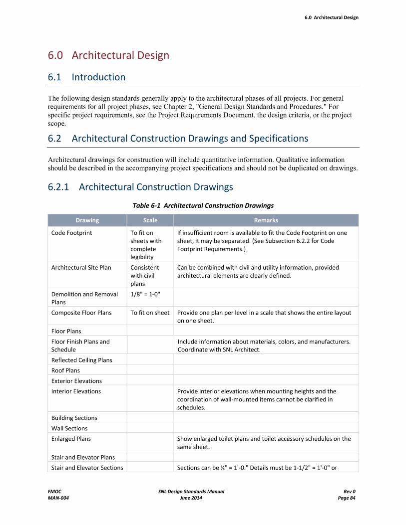
6.0 Architectural Design
FMOC SNL Design Standards Manual Rev 0MAN-004 June 2014 Page 84
6.0 Architectural Design
6.1 Introduction
The following design standards generally apply to the architectural phases of all projects. For general requirements for all project phases, see Chapter 2, "General Design Standards and Procedures." For specific project requirements, see the Project Requirements Document, the design criteria, or the project scope.
6.2 Architectural Construction Drawings and Specifications
Architectural drawings for construction will include quantitative information. Qualitative information should be described in the accompanying project specifications and should not be duplicated on drawings.
6.2.1 Architectural Construction Drawings
Table 6-1 Architectural Construction Drawings
Drawing Scale Remarks
Code Footprint To fit on sheets with complete legibility
If insufficient room is available to fit the Code Footprint on one sheet, it may be separated. (See Subsection 6.2.2 for Code Footprint Requirements.)
Architectural Site Plan Consistent with civil plans
Can be combined with civil and utility information, provided architectural elements are clearly defined.
Demolition and Removal Plans
1/8" = 1-0"
Composite Floor Plans To fit on sheet Provide one plan per level in a scale that shows the entire layout on one sheet.
Floor Plans
Floor Finish Plans and Schedule
Include information about materials, colors, and manufacturers. Coordinate with SNL Architect.
Reflected Ceiling Plans
Roof Plans
Exterior Elevations
Interior Elevations Provide interior elevations when mounting heights and the coordination of wall-mounted items cannot be clarified in schedules.
Building Sections
Wall Sections
Enlarged Plans Show enlarged toilet plans and toilet accessory schedules on the same sheet.
Stair and Elevator Plans
Stair and Elevator Sections Sections can be ¼" = 1'-0." Details must be 1-1/2" = 1'-0" or
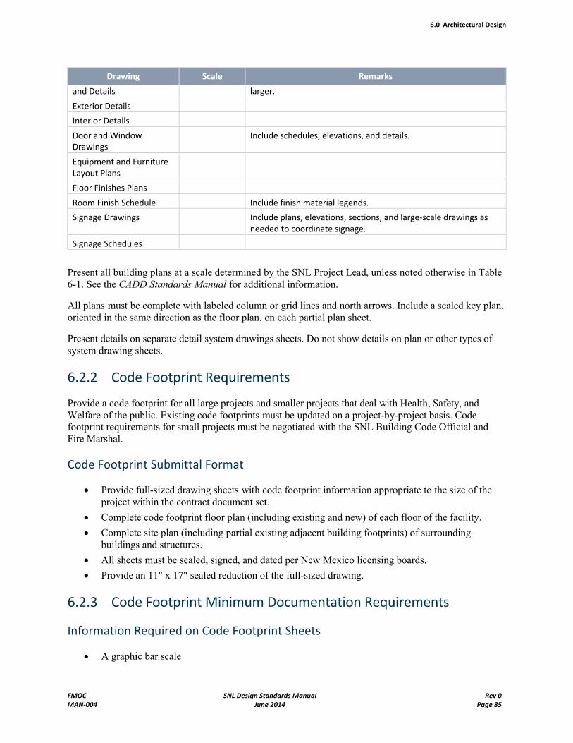
6.0 Architectural Design
FMOC SNL Design Standards Manual Rev 0MAN-004 June 2014 Page 85
Drawing Scale Remarks
and Details larger.
Exterior Details
Interior Details
Door and Window Drawings
Include schedules, elevations, and details.
Equipment and Furniture Layout Plans
Floor Finishes Plans
Room Finish Schedule Include finish material legends.
Signage Drawings Include plans, elevations, sections, and large-scale drawings as needed to coordinate signage.
Signage Schedules
Present all building plans at a scale determined by the SNL Project Lead, unless noted otherwise in Table 6-1. See the CADD Standards Manual for additional information.
All plans must be complete with labeled column or grid lines and north arrows. Include a scaled key plan, oriented in the same direction as the floor plan, on each partial plan sheet.
Present details on separate detail system drawings sheets. Do not show details on plan or other types of system drawing sheets.
6.2.2 Code Footprint Requirements
Provide a code footprint for all large projects and smaller projects that deal with Health, Safety, and Welfare of the public. Existing code footprints must be updated on a project-by-project basis. Code footprint requirements for small projects must be negotiated with the SNL Building Code Official andFire Marshal.
Code Footprint Submittal Format
Provide full-sized drawing sheets with code footprint information appropriate to the size of the project within the contract document set.
Complete code footprint floor plan (including existing and new) of each floor of the facility.
Complete site plan (including partial existing adjacent building footprints) of surrounding buildings and structures.
All sheets must be sealed, signed, and dated per New Mexico licensing boards.
Provide an 11" x 17" sealed reduction of the full-sized drawing.
6.2.3 Code Footprint Minimum Documentation Requirements
Information Required on Code Footprint Sheets
A graphic bar scale
6.0 Architectural Design
FMOC SNL Design Standards Manual Rev 0MAN-004 June 2014 Page 86
North arrow
All permanent partitions 5'-9" or taller
Each room numbered and labeled. (Keynoting or legends are not acceptable.)
Occupant load under the room name
Common path of travel liner notation with exiting count per exit
Identification of new construction, building additions, existing to remain, remodeled areas, and areas relocated
Stair and shaft enclosures with minimum fire-resistive openings allowed
Ramps, landings, and railings
The perimeter of all rated corridors with minimum fire-resistive openings allowed
Occupancy separations or protection from hazards
Fire-rated area separation walls
Separation of construction types
Required opening ratings
All horizontal exits or smoke partitions with opening ratings
Location of central fire alarm control panel and any remote annunciator panels
Fire department supply connections and access roads
Distances to property line
Distances to adjoining buildings when within 60 feet
Location of any anticipated future additions (dotted lines)
6.2.4 Minimum Information Required on Code Footprint Sheets
Indication of which codes the new construction work is designed to (IBC and family of codes and any additional DOE/SNL regulations specifically applicable to the building use).
Type of construction: New, addition, renovation, changes in use
Reason for submittal: New construction, new licensure, or plan of corrections
Location: Street name, Technical Area, SNL site
Customer information: Name, organization, office location, phone, facsimile number
Date of plan edition (or revision)
Name of local fire department (KAFB Fire Department)
Name of local building inspection department (when available)
Each portion of a building on each side on a compliant fire-resistive area separation
Walls, new or existing
Each occupancy group and type
Construction type
Total allowed area per floor
Actual floor area
Approximate grade elevation at each corner of the building and finish floor
Allowed stories and height limitations
6.0 Architectural Design
FMOC SNL Design Standards Manual Rev 0MAN-004 June 2014 Page 87
Actual height
Mixed-ratio calculations, as required
Structural fire protection ratings
Interior bearing walls
Exterior bearing walls
Exterior nonbearing walls
Structural framing information
Permanent partitions
Shaft enclosures
Floors
Roofs
Exterior openings
Proposed UL, FM, or other Fire-Assembly Numbers (if available)
Fire safety features including the following: Sprinklers, standpipes, fire alarms, and fire extinguishers
Smoke detectors, battery emergency lighting, exit lights, emergency power generators
Hood-Suppression Systems; any other special systems, fire lanes, disconnect switches
Locations and fire department connections
Accessible building and site features related to the Architectural Barriers Act
Plumbing fixture type and count
6.3 Architectural Design Requirements
The following information is general guidance. For project-specific requirements, see the design criteria.
6.3.1 Site Development
Site Furniture
See the Campus Design Guidelines (CDG) for Sandia National Laboratories New Mexico (SNL/NM) and SNL Standard Specification 12930, Site Furnishings.
Exterior Signage
See the Campus Design Guidelines and the Sign Standard for Exterior and Interior Signs.
Site Lighting
See Chapter 9, "Exterior Lighting Systems Design," and the Campus Design Guidelines.
6.0 Architectural Design
FMOC SNL Design Standards Manual Rev 0MAN-004 June 2014 Page 88
6.3.2 Building Subculture
Foundations
A dense concrete foundation with adequate control joints generally does not need to be waterproofed or dampproofed in locations where the groundwater level is significantly below the foundation. Grade the site to drain surface water away from the building. Protect masonry walls below grade against leakage by using suitable cement parging and bituminous coatings or membrane applications.
Perimeter Insulation
See SNL Standard Specification 07200, Building Insulation.
Waterproofing and Wall Vapor Retarders
See SNL Standard Specification 07200, Building Insulation.
6.3.3 Building Shell
Exterior Walls
Use lightweight materials for floors, walls, partitions, and other building components where consistent with programmatic or operating requirements, economic objectives, fire protection and other safety requirements, and where no overriding acoustical requirements exist.
If the wall is to act as a filler or curtain wall, the connections to the structure must be capable of allowing the structure to deflect and yet maintain structural and weather-resisting integrity.
For exposed exterior walls, consider masonry composite walls, insulated metal, or concrete panels and other prefabricated wall construction.
Where side-hill sites require use of concrete retaining walls, use these walls as building walls where practicable to achieve economy in construction.
Where the lower portion of exterior walls is subject to damage from vehicle traffic, material handling, or other activities, select a proper material and material thickness, or possibly provide a protective wainscot. Protect exposed insulation, light-metal construction, or frangible materials from activities that could cause damage.
Design story heights and bay sizes to accommodate coursing. Lay out masonry walls in even coursing to fit between beams, columns, and standard-size openings to minimize cutting of masonry units.
Exterior Finishes
In general, exterior finishes should be kept simple. Concrete walls should be left natural and unpainted, unless economical finishing methods can be employed or where aesthetics and operating considerations require finishing. When using color treatment on exterior walls, select colors to harmonize with the environment and natural setting. Limit the number of colors used for a building or complex and carefully
6.0 Architectural Design
FMOC SNL Design Standards Manual Rev 0MAN-004 June 2014 Page 89
select them to provide a dignified public image. Contact the SNL Architect for approval of color and material selections.
Expansion Control
Provide adequate control and expansion joints when poured concrete floors or concrete or masonry walls are used. In long walls, carefully design and locate control joints to confine the effects of total expansion and contraction. In addition, provide necessary bond beams and anchors to structural framing for masonry units, and provide flashing, bond breaks, and weep holes to minimize the potential for moisture buildup and cracking because of differential movement.
Provide joints across buildings larger than 200 feet in length and where buildings have a significant change in plan dimension. Provide joints that can accommodate thermal-, moisture-, and seismic-related movements. Structural expansion joints should extend from the roof to the foundation without offsets. Building expansion joints should not be less than 1-inch wide and should be designed to permit independent vertical and horizontal movements of the elements on either side of them.
Investigate manufacturers' research data and recommendations to realize optimum performance of various materials.
Joint Sealers
See SNL Standard Specification 07900, Joint Sealants.
Painting
See SNL Standard Specification 09900, Painting.
Waterproofing and Dampproofing
Protect masonry walls above grade against moisture penetration by means such as the following:
Adequately filled, compressed joints
Cement coatings
Lintel and sill flashing
Flashing or weather-break offsets at spandrels
Overlapping weather-breaks where masonry abuts columns and beams
Vapor Retarders and Insulation
In general, the "U" factors for insulation should meet the requirements set forth in the 2009 IECC. Where composite walls are used, consider the compatibility of the insulating and facing materials. Vapor barriers and fibrous insulation must be noncombustible or labeled by Underwriters Laboratories® (UL) as meeting a Flame Spread Rating of 25 or less and a Smoke Developed Value of 50 or less. For cavity walls, the use of treated (water-repellent), granular fill might be appropriate. Rigid-board insulation of cellular materials generally retains its insulating values longer than fibrous materials that are more vulnerable to moisture.
Foamed-plastic insulation in exterior walls must be separated from the interior of the building by 5/8-inch, type-X, fire-rated gypsum board, or an equivalent fire barrier.
6.0 Architectural Design
FMOC SNL Design Standards Manual Rev 0MAN-004 June 2014 Page 90
Vapor barriers might be required in buildings with high winter humidity loads. Use the barriers with insulation, and locate them to avoid condensation in the insulation.
Parapets
Tops of parapet walls must be capped with metal prefabricated roof specialty components.
Building Numbers
Provide building numbers on each major elevation as needed to be visible from approaching vehicles and pedestrians. Additional guidance for this section is in the Sign Standard for Exterior and Interior Signs.
Roof Construction
For single-sheet metal roof decking, specify a minimum thickness of 22 gauge unless otherwise required by Factory Mutual® (FM) or Class I roofs. Design the decking to limit deflection and protect the roofing from subsequent damage. Avoid using lightweight concrete over a metal deck.
Expansion Control
Expansion joints in the roof assembly (including the roof deck) must be placed in the same location as the building's structural expansion joints. The joints must extend across the entire width of the roof and must never terminate short of the roof edge or perimeter. The joints must be designed to accommodate contraction as well as expansion. Expansion joints should always be provided at the following locations:
Where expansion joints are provided in the structural system
Where steel framing, structural steel, or decking change direction
Where separate wings of L, U, T, or similar wings exist
Where the type of decking changes (steel to concrete)
Where additions are connected to existing buildings
Where movement between vertical walls and the roof deck might occur
Locate expansion joints at roof high points; water should drain in opposite directions from each side of the joint. Elevate the expansion joint above the highest expected level of water flow to prevent obstruction of water flow off a roof.
Decks, Slabs, and Sheathing
Coordinate design materials and methods with SNL Architect.
Vapor Retarders and Insulation
As a general guide, vapor retarders should be considered when both the outside average January temperature is below 40°F, and the expected interior winter relative humidity is 45 percent or greater. The building usage must be considered in determining the need for a vapor retarder.
If vapor retarders are used, they should be constructed of materials that are compatible with the other roof system components. The designer should pay particular attention to flashing details at edge seals and at all penetrations through the vapor retarder to ensure its moisture-tight integrity.
6.0 Architectural Design
FMOC SNL Design Standards Manual Rev 0MAN-004 June 2014 Page 91
Use only insulation approved for UL Class A and FM Class I roof construction on roofs. All roof insulation must comply with the NRCA Roofing Manual published by the National Roofing Contractors Association.
Roof insulation should be installed in two layers when thickness permits, with all joints offset between the upper and lower layers. Mechanical fasteners should be used over steel decks to attach the first layer of insulation. For concrete decks, the first layer should typically be hot asphalt mopped to the concrete. The second layer should be fully adhered to the first layer and generally have the higher insulation value. The long dimension of the insulation boards should be laid perpendicular to the flow of water.
Performance type specifications should be avoided when specifying any insulation since manufacturers'data may vary considerably. The designer should list the appropriate ASTM specification, the thickness requirement, and the C or R value for any insulation board to be used in roof construction.
Roof Covering
Roof membranes must be a 60-mil single-ply type of TPO or PVC depending on the roof construction and type of building. The SNL/NM Roofing Program Manager must provide guidance in deciding the type of membrane to be specified. In addition, SNL/NM construction standard specifications for each type of roof membrane must be provided and must be used in their entirety. Any modifications to the specifications must be brought to the attention of the assigned Engineering Standard Program Committee member. UL Class A ratings are required for all roof membranes.
Flashing
Membrane flashing materials must exhibit some degree of flexibility, be compatible with roofing membrane material, be resistant to traffic and natural damage, and be durable and weather-resistant. In general, they should be constructed with materials similar to those used in the construction of the roof membrane. Minimum heights of base flashings should be 8 inches.
Accessory metal should be used for covers, watersheds, or fascia, but typically should not be incorporated into the roofing membrane. Minimize direct contact of dissimilar metals to avoid electrolytic action.
Surface-mounted wall reglets are to be used in lieu of embedded types. Positive attachment using screws or bolts is required.
Drainage
Design and build all roofs to ensure positive, thorough drainage. The designer must make provisions for positive drainage per the NRCA guidelines. The structural framing, deck type, roof membrane, roof deflections, and building layout must all be considered in determining the necessary slope.
Locate drains at points of maximum deflection (that is, midspan) and not adjacent to columns, load-bearing walls, or any other structural member supported by the ground. If drains are required to be placed at columns or bearing walls, the slope of the roof must be increased to compensate for the minimum deflections at these locations. Roof drain spacing must not exceed 75 feet in any direction. After drain locations are selected and deflections computed, the designer must provide additional slope to ensure positive drainage. A minimum slope of 1/8 inch per foot should be added to the deflection computation. Structural decks that incorporate camber (precast concrete) must be considered in the design of the drainage slope system.
6.0 Architectural Design
FMOC SNL Design Standards Manual Rev 0MAN-004 June 2014 Page 92
Drains should be recessed (sumped) below the roof surface with sufficient insulation placed around the drains to prevent condensation. Drainage crickets should be provided between drains and on the high side of mechanical curbs. Provide roof drains with a minimum 4 inch-diameter pipe size in lieu of gutters and downspouts. Provide a secondary drainage system (overflow scupper) on all roofs with parapets or curbs. The secondary system must not be tied to the storm sewer and should drain to a highly visible area. The weight of retained water including that attributed to deflection of the roof because of the load of water below the bottom level of the overflow outlets must be included in the structural calculations. Roof drains, gutters, and downspouts should be equipped with metal strainers to prevent obstructions by debris. Use seamless, one-piece gutters, downspouts, and splash blocks as much as possible.
Mechanical Curbs and Penetrations
Every roofing penetration is a potential source of water entry. Roof life can be maximized and roof maintenance lessened by minimizing the amount of rooftop equipment and penetrations. Wherever possible, place building equipment within a penthouse or inside the building. Where possible, combine utilities below the deck.
Where rooftop equipment installation is unavoidable, use supporting frames with round legs of sufficient height above the roof to allow easy maintenance and replacement without alterations. Follow the guidelines provided by the NRCA. Curbs are to be positively attached to the structural deck and located away from low spots in the roof.
Adequate space should be provided among mechanical units, penetrations, and walls so roofing materials can be installed correctly. Locate conduits, pipes, and other utilities at least 12 inches apart where they pass through the roof, unless placed in a properly flashed curb opening. Base flashing should extend a minimum of 8 inches above the roofline. Coordinate all mechanical and electrical penetrations with the architectural roof drawings.
All penetration details require special attention. Every penetration should be addressed and appropriate flashing details specified rather than using typical details. Pitch pans or pockets are not acceptable. Use pipe boots or single-ply membrane flashings in general. Refer to the NRCA Roofing Manual and the SMACNA Architectural Sheet Metal Manual, or appropriate flashing details.
Protection and Maintenance
Provide wear-resistant roof walkways, compatible with the roof membrane material, from points of roof access to penthouse entrances and to all roof-mounted and roof-accessible equipment that requires routine inspection and servicing. Movement of heavy equipment across a roof can cause permanent structural deflections and should be avoided. Specify a crane to place equipment where possible.
Reroofing
Design all reroofing projects following the principles stated above. In general, if the insulation is wet or is suspected to be wet, a complete tear-off down to the structural deck is required. Locate and note all rooftop equipment on the plan drawings. Disconnect all equipment, utilities, and curbs, and raise to the proper height. Remove abandoned equipment from the roof.
Each reroofing project is unique. Discuss the design of the reroofing in detail with the SNL/NM Roofing Program Manager prior to any design.
6.0 Architectural Design
FMOC SNL Design Standards Manual Rev 0MAN-004 June 2014 Page 93
Openings
Skylights – Coordinate with the SNL Architect.
Hatches – Coordinate with the SNL Architect.
Fall Protection
See the requirements in Chapter 2 of this manual.
Canopies
Coordinate the design and requirements with the SNL Architect.
Exterior Openings
The design of external openings must respond to the internal functional needs of the building owners and users and also must respond to the guidelines of the SNL campus. The Campus Design Guidelines and the Long-Range Development Plan (LRDP) describe high-level principles to consider during design development. Circulation and Interaction, Parking, Safety, Security, Sustainability, Entrances and Approaches, Renovation and Historic Preservation are chapters in the CDG that provide guidance. Internal Destinations and Connections, Safety and Security, Surety (Architectural Surety®), and sustainability are guiding principles in the LRDP that guide the Project Manager and the design team. The location of entrances must relate to pedestrian corridors, public spaces, and parking access. Service entrances must relate to service corridors identified in the Master Plans for zone of the campus. Windows should be oriented toward view corridors, landscape areas, and pedestrian malls when possible. Windows should be oriented to respond to sun and shade, and to promote natural lighting into the building. The selection of materials to be used on all exterior openings must have sustainable characteristics and be energy-efficient.
Exterior entrances and exit ways must provide accessibility, must be designed to be safe, and must follow applicable building codes and life safety codes.
Exterior openings must provide appropriate security depending upon the needs of owners and users. Protect openings in exterior walls and roofs of buildings that are designated as a security area boundary or that are the boundary to an interior vault or vault-type room. Exterior openings larger than 96 square inches in area, larger than 6 inches in the smallest dimension (greater than 11 inches in diameter) require protection. Openings include, but are not limited to, roof hatches, skylights, doors, windows, ducts, crawlways, tunnels and sewers. (See Chapter 11 for additional requirements.)
Exterior openings, specifically windows, in older buildings should be replaced with energy-efficient products that retain the aesthetic intent of the original design. Brick buildings built in the 1950s are not on the registry of the State Historical Preservation Office (SHPO), but have historical significance to the campus, and it is desirable to preserve the design intent of exterior features when possible.
Windows
Design windows to respond to the High-Performance and Sustainable Buildings Guiding Principles. The selection of glazing must respond to the energy efficiency of the building in regard to orientation for solar gain and insulation to reduce energy consumption. Design windows to be of stock sizes and competitive
6.0 Architectural Design
FMOC SNL Design Standards Manual Rev 0MAN-004 June 2014 Page 94
design. Use the more economical industrial and energy-efficient types when practical. Select windows to fit masonry coursing and the specified building module.
All windows must be at a minimum double-pane insulating windows.
For windows without security grills that are larger than 96 square inches and below 18 feet above ground level, use burglar-resistant glass as one of the two window panes, and put all glazing stops on the inside of the building.
NOTE Vaults must be constructed without windows. Closed areas (formerly called vault-type rooms or VTRs) and security area boundaries must be constructed without windows unless absolutely necessary. Security requirements for windows and openings in vaults, closed areas, and security area boundaries are described in Chapter 11 of this manual.
Doors
Aluminum and glass storefront doors (medium- or wide-stile) may be used for main entrances. Other exterior doors are usually flush, hollow metal, minimum 16 gauge in 14-gauge metal frames. Interior doors are usually flush, hollow metal, minimum 18 gauge in 16- or 14-gauge metal frames. Provide vision panels in doors in high-traffic areas and at all doors that swing into common hallways, corridors, or circulation areas. Specify properly labeled UL doors for all fire doors. Solid-core wood doors in hollow metal frames may be used in some administrative areas.
Use heavy-duty steel, roll-up, sectional, and other vertical doors in shops, warehouses, and industrial buildings for equipment and vehicular access. These doors should be weather-stripped in the best manner possible. Give special attention to the attachment and bracing of tracks and guides to ensure proper operation and minimize maintenance. Bolt, rather than weld, all track attachments to the structure to allow for maintenance adjustment. Support doorframes rigidly to prevent cracking of adjacent finishes during normal use. For Security applications, see Chapter 11, "Security Design Standards."
Hardware
Ensure that all builder's hardware is utilitarian, economically competitive, and suitable for the required functions. Builder's hardware must also meet handicapped accessibility requirements. Hardware must be of durable grade and consistent with all appropriate SNL/NM standard specifications and the International Building Code.® Location of hardware must also meet handicapped accessibility requirements. Avoid using concealed door closers when possible.
Provide an automatic door operator or other form of handicapped accessible assistance at main entrances to new buildings. Exterior door hinges must be either nonremovable or fast-pin. Use fire-rated hardware at all fire-rated door assemblies. Do not use fusible link arms on fire door closers except when permitted by the fire protection engineer. Occasionally fire doors need to be held open, use electromagnetic hold-open devices actuated by the building fire alarm system.
To be compatible with Sandia National Laboratories/New Mexico (SNL/NM) master keying system, all locksets must use Sargent zero or 1-bitted, 6-pin cylinders. Levels of security are assigned to hardware by the SNL Security Lock and Key Program. Once the levels of security have been assigned to the hardware,keyways must be selected by the SNL/NM locksmith. Pushbutton combination locks must be used for administrative locks only and must include a Best small-format interchangeable core. See SNL Standard Specification 08710, Door Hardware, for hardware requirements.
Security-Type Locks
6.0 Architectural Design
FMOC SNL Design Standards Manual Rev 0MAN-004 June 2014 Page 95
The design of door and hardware systems in security areas must follow guidelines established by SNL Physical Security (see Chapter 11). Involve SNL Security Lock and Key service during the early design phase to determine whether any existing door hardware might be considered a security lock. Common applications that require security locks include Closed Areas (CA), Vault-Type Rooms (VTRs), High-Security Buildings (HSB), limited area boundaries, exterior doors, gates, and Internal Distribution Rooms (IDR). Other not-so-common applications that might be considered security locks exist. All security locks and keys must be accounted for at all times by Physical Security and must not be removed by any personnel except the Physical Security Locksmith. The hardware designer must provide notes within the construction documents instructing the contractor to contact SNL Security Lock and Key services before removing any doors that contain security hardware. The importance of proper accountability of security locks and cylinders must be conveyed to the general contractor. Refer to SNL Standard Specification 08710, Door Hardware, for information about contractor accountability and the "preliminary hardware submittal conference."
The standard hardware to be used on Closed Areas, VTRs, and other high-security applications is the LKM-7003 series by Lockmasters; it is the approved lockset that meets security requirements. This lockset is used with a spin-dial lock. There are three options for the design of doors within these spaces:
Option 1: On outward-swinging doors, provide the LKM 7003 series lockset.
Option 2: On inward-swinging doors, provide the LKM 7003 series lockset and one additional exit with standard door hardware on inside and blank face on exterior side.
Option 3: Provide alternative design approach, and request approval from the Site Fire Marshal if Option 1 or 2 is not feasible.
6.3.4 Interiors
Partitions
Provide fire-separation walls (occupancy separation type and area separation type) as required by the IBC and the National Fire Protection Association (NFPA) for separation of dissimilar occupancies or hazards, equipment rooms, stairwells, occupancy values, and as required to limit maximum floor areas.
Interior walls and partitions may be composed of materials similar to those used for exterior walls.Interior walls may also be prefabricated and either fire-resistant or noncombustible. Materials used for fire-separation walls must have the required UL-listed fire rating. On the floor plans, identify all walls (rated and nonrated) with a keyed note or a legend. Materials used for vault, closed area, and security area walls must meet the requirements in Chapter 11.
Specify that temporary interior construction barriers be covered with Type-X gypsum wallboard and painted to match existing wall surfaces when the barriers are intended to be in place for a significant amount of time, when the barriers are located in a highly visible area, or both.
Observe the following limitations:
Restrict the use of plaster to areas where the specific operation requires its use.
Paint masonry walls where required by occupancy; otherwise, leave unfinished. Paint or seal masonry walls in equipment rooms and utility chases.
Use 5/8-inch-thick Type-X gypsum wallboard throughout, with taped joints. For project-specificrequirements, see the Design Criteria or contact the Sandia Designated Representative (SDR).
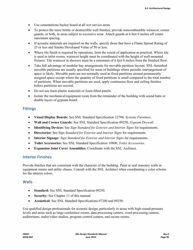
6.0 Architectural Design
FMOC SNL Design Standards Manual Rev 0MAN-004 June 2014 Page 96
Use cementations backer board at all wet service areas.
To protect the more brittle or destructible wall finishes, provide noncombustible wainscot, corner guards, or both, in areas subject to excessive wear. Attach guards at 6 feet 0 inches off center maximum spacing.
If acoustic materials are required on the walls, specify those that have a Flame Spread Rating of 25 or less and Smoke Developed Value of 50 or less.
Where tile finish is required by operations, limit the extent of application as practical. Where tile is used in toilet rooms, wainscot height must be coordinated with the height of wall-mounted fixtures. Tile wainscot in showers must be a minimum of 6 feet 0 inches from the finished floor.
Take full advantage of modular bay arrangements for movable partition layouts. SNL-furnished movable partitions are usually specified for areas of buildings where periodic rearrangement of space is likely. Movable parts are not normally used as fixed partitions around permanently assigned space except where the quantity of fixed partitions is small compared to the total number of partitions. When movable partitions are used, apply continuous floor and ceiling finishes before partitions are erected.
Do not use foam plastic materials or foam-filled panels.
Isolate the mechanical/equipment room from the remainder of the building with sound batts or double layers of gypsum board.
Fittings
Visual Display Boards: See SNL Standard Specification 12700, Systems Furniture.
Wall and Corner Guards: See SNL Standard Specification 09250, Gypsum Drywall.
Identifying Devices: See Sign Standard for Exterior and Interior Signs for requirements.
Directories: See Sign Standard for Exterior and Interior Signs for requirements.
Interior Signage: Sign Standard for Exterior and Interior Signs for requirements.
Toilet Accessories: See SNL Standard Specification 10800, Toilet Accessories.
Expansion Joint Cover Assemblies: Coordinate with the SNL Architect.
Interior Finishes
Provide finishes that are consistent with the character of the building. Paint or seal masonry walls in equipment rooms and utility chases. Consult with the SNL Architect when coordinating a color scheme for the interior colors.
Walls
Standard: See SNL Standard Specification 09250.
Security: See Chapter 11 of this manual.
Acoustical: See SNL Standard Specifications 07200 and 09250.
Use qualified design professionals for acoustic design, particularly in areas with high-sound-pressure levels and areas such as large conference rooms, data processing centers, word processing centers, auditoriums, audio/video studios, program control centers, and secure rooms.
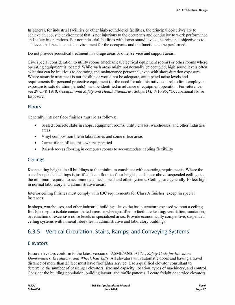
6.0 Architectural Design
FMOC SNL Design Standards Manual Rev 0MAN-004 June 2014 Page 97
In general, for industrial facilities or other high-sound-level facilities, the principal objectives are to achieve an acoustic environment that is not injurious to the occupants and conducive to work performance and safety in operations. For nonindustrial facilities with lower sound levels, the principal objective is to achieve a balanced acoustic environment for the occupants and the functions to be performed.
Do not provide acoustical treatment in storage areas or other service and support areas.
Give special consideration to utility rooms (mechanical/electrical equipment rooms) or other rooms where operating equipment is located. While such areas might not normally be occupied, high sound levels often exist that can be injurious to operating and maintenance personnel, even with short-duration exposure. Where acoustic treatment is not feasible or would not be adequate, anticipated noise levels and requirements for personal protective equipment (or the need for administrative control to limit employee exposure to safe duration periods) must be identified in advance of equipment operation. For reference, see 29 CFR 1910, Occupational Safety and Health Standards, Subpart G, 1910.95, "Occupational Noise Exposure."
Floors
Generally, interior floor finishes must be as follows:
Sealed concrete slabs in shops, equipment rooms, utility chases, warehouses, and other industrial areas
Vinyl composition tile in laboratories and some office areas
Carpet tile in office areas where specified
Raised-access flooring in computer rooms to accommodate cabling flexibility
Ceilings
Keep ceiling heights in all buildings to the minimum consistent with operating requirements. Where the use of suspended ceilings is justified, keep floor-to-floor heights, and space above suspended ceilings to the minimum required to accommodate mechanical and other systems. Ceilings are generally 10 feet high in normal laboratory and administrative areas.
Interior ceiling finishes must comply with IBC requirements for Class A finishes, except in special instances.
In shops, warehouses, and other industrial buildings, leave the basic structure exposed without a ceiling finish, except to isolate contaminated areas or where justified to facilitate heating, ventilation, sanitation, or reduction of excessive noise levels in specialized areas. Provide economically competitive, suspended ceiling systems with mineral fiber tiles in administrative and laboratory buildings.
6.3.5 Vertical Circulation, Stairs, Ramps, and Conveying Systems
Elevators
Ensure elevators conform to the latest version of ASME/ANSI A17.1, Safety Code for Elevators, Dumbwaiters, Escalators, and Wheelchair Lifts. All elevators with automatic doors and having a travel distance of more than 25 feet must have firefighter service. Use a qualified elevator consultant to determine the number of passenger elevators, size and capacity, location, types of machinery, and control. Consider the building population, building layout, and traffic patterns. Locate freight or service elevators
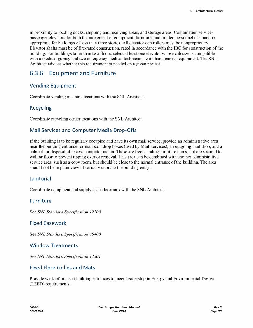
6.0 Architectural Design
FMOC SNL Design Standards Manual Rev 0MAN-004 June 2014 Page 98
in proximity to loading docks, shipping and receiving areas, and storage areas. Combination service-passenger elevators for both the movement of equipment, furniture, and limited personnel use may be appropriate for buildings of less than three stories. All elevator controllers must be nonproprietary.Elevator shafts must be of fire-rated construction, rated in accordance with the IBC for construction of the building. For buildings taller than two floors, select at least one elevator whose cab size is compatible with a medical gurney and two emergency medical technicians with hand-carried equipment. The SNL Architect advises whether this requirement is needed on a given project.
6.3.6 Equipment and Furniture
Vending Equipment
Coordinate vending machine locations with the SNL Architect.
Recycling
Coordinate recycling center locations with the SNL Architect.
Mail Services and Computer Media Drop-Offs
If the building is to be regularly occupied and have its own mail service, provide an administrative area near the building entrance for mail stop drop boxes (used by Mail Services), an outgoing mail drop, and a cabinet for disposal of excess computer media. These are free-standing furniture items, but are secured to wall or floor to prevent tipping over or removal. This area can be combined with another administrative service area, such as a copy room, but should be close to the normal entrance of the building. The area should not be in plain view of casual visitors to the building entry.
Janitorial
Coordinate equipment and supply space locations with the SNL Architect.
Furniture
See SNL Standard Specification 12700.
Fixed Casework
See SNL Standard Specification 06400.
Window Treatments
See SNL Standard Specification 12501.
Fixed Floor Grilles and Mats
Provide walk-off mats at building entrances to meet Leadership in Energy and Environmental Design (LEED) requirements.
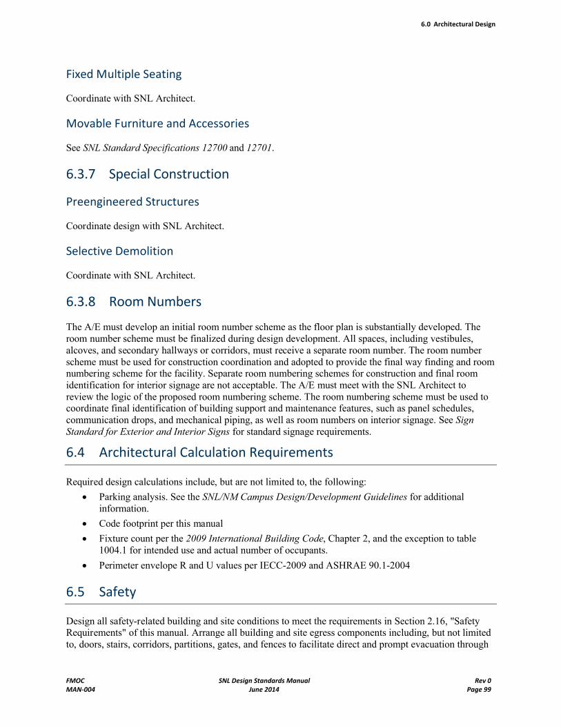
6.0 Architectural Design
FMOC SNL Design Standards Manual Rev 0MAN-004 June 2014 Page 99
Fixed Multiple Seating
Coordinate with SNL Architect.
Movable Furniture and Accessories
See SNL Standard Specifications 12700 and 12701.
6.3.7 Special Construction
Preengineered Structures
Coordinate design with SNL Architect.
Selective Demolition
Coordinate with SNL Architect.
6.3.8 Room Numbers
The A/E must develop an initial room number scheme as the floor plan is substantially developed. The room number scheme must be finalized during design development. All spaces, including vestibules, alcoves, and secondary hallways or corridors, must receive a separate room number. The room number scheme must be used for construction coordination and adopted to provide the final way finding and room numbering scheme for the facility. Separate room numbering schemes for construction and final room identification for interior signage are not acceptable. The A/E must meet with the SNL Architect to review the logic of the proposed room numbering scheme. The room numbering scheme must be used to coordinate final identification of building support and maintenance features, such as panel schedules, communication drops, and mechanical piping, as well as room numbers on interior signage. See Sign Standard for Exterior and Interior Signs for standard signage requirements.
6.4 Architectural Calculation Requirements
Required design calculations include, but are not limited to, the following:
Parking analysis. See the SNL/NM Campus Design/Development Guidelines for additional information.
Code footprint per this manual
Fixture count per the 2009 International Building Code, Chapter 2, and the exception to table 1004.1 for intended use and actual number of occupants.
Perimeter envelope R and U values per IECC-2009 and ASHRAE 90.1-2004
6.5 Safety
Design all safety-related building and site conditions to meet the requirements in Section 2.16, "Safety Requirements" of this manual. Arrange all building and site egress components including, but not limited to, doors, stairs, corridors, partitions, gates, and fences to facilitate direct and prompt evacuation through
6.0 Architectural Design
FMOC SNL Design Standards Manual Rev 0MAN-004 June 2014 Page 100
and away from the building in an emergency. All egress components must conform to the applicable requirements of the 2009 International Building Code, the 2009 International Existing Building Code,and the 2010 Americans with Disabilities Act and Architectural Barriers Act Accessibility Guidelines (ADA and ABAAG).
6.6 Accessibility Requirements
Design all new buildings, and all additions and renovations to existing facilities, to be safe and readily accessible to, and usable by, individuals with disabilities. Elements that require consideration include parking (refer to the Campus Design and Development Guidelines for quantity requirements), access routes or path of travel, signage, entrances and vestibules, ramps, landings, stairs, doors, restrooms, assembly spaces, water fountains, access control, telephones, elevators, and common-use spaces. The Americans with Disabilities Act and Architectural Barrier Act Accessibility Guidelines for Buildings and Facilities (ADA and ABAAG) have published guidance for design of these facilities. Buildings and sites at Sandia National Laboratories will follow "Part II: ABA Application and Scope," as stated in the preamble: The ABA covers facilities that are designed, built, altered, or leased with federal funds. The Architectural Accessibility Review Board (AARB) at SNL provides guidance on accessibility issues that require resolution because of interpretations or conflict of the Guidelines. The building design must also allow for safe egress of individuals with disabilities in an emergency. Provide Areas of Rescue Assistance as required by codes, accessibility guidelines, or as designated by the AARB.
7.0 Fire Protection Design
FMOC SNL Design Standards Manual Rev 0MAN-004 June 2014 Page 101
7.0 Fire Protection Design
7.1 Introduction
Sandia National Laboratories (SNL) is committed to protecting workers, the public, the environment, and property from fire and its related hazards through the execution of a comprehensive Corporate Fire Protection Program. SNL shall comply with the fire protection requirements as delineated to the Contractor via DOE Order 420.1B Contractor Requirements Document (CRD) and 10 CFR 851 and the referenced codes and standards therein. Other requirements may be added by the SFO Manager as the designated Authority Having Jurisdiction (AHJ) as defined in DOE O 420.1B and by the Corporate Fire Marshall. DOE implementation guidance and technical standards referenced in DOE O 420.1B are not mandatory but must be considered in conjunction with specific requirements.
The concepts of Highly Protected Risk and defense-in-depth will be applied in a risked-based approach to comply with contractual requirements, to achieve DOE fire safety objectives and mission success, and to drive continuous improvement. SNL will meet or exceed the minimum requirements established by the National Fire Protection Association (NFPA), model building codes, and DOE Order 420.1B requirements. Alternate methods that satisfy the requirements must be justified to ensure that an adequate level of safety commensurate with identified hazards is achieved, and the method shall be approved by the AHJ prior to its implementation.
7.1.1 New Construction and Modifications
Ensure all new construction complies with the national consensus industry standards and the model building codes applicable for the state or region supplemented in a graded manner per Corporate Procedure FAC100.3.3, Enforce Building Codes. All facility modifications shall be constructed to meet codes and standards in effect when the design criteria are approved, otherwise known as the Code of Record (COR). Provisions of subsequent editions of codes or standards (promulgated after the COR) will be met to the extent that they are explicitly stated to be applicable to existing facilities. Other provisions of updated codes and standards must be applied to existing facilities when a construction modification takes place or when a potential for immediate risk to life safety or health has been identified.
7.1.2 Highly Protected Risk Status
Provide a level of safety sufficient to fulfill the requirements of highly protected risk (HPR). HPR is a rating given to property that qualifies for insurance coverage by industrial insurance companies that limits their insurance underwriting to this best-protected class of risk. This level of safety is established by applying a graded approach and experience in the application of insurance industry standards to determine the appropriate HPR provisions. Refer to the FM Global Property Loss Prevention Datasheets for engineering guidelines.
7.1.3 Fire Hazard Analyses
A fire hazard analysis (FHA) shall be developed, using a graded approach, for all hazard category 1, 2, and 3 nuclear facilities, significant new facilities (as determined by the AHJ), and facilities that represent unique fire safety risks. This includes planned facilities and significant renovations to existing facilities.
7.0 Fire Protection Design
FMOC SNL Design Standards Manual Rev 0MAN-004 June 2014 Page 102
In accordance with the graded approach concept, the level of detail in the FHA is directly related to the complexity of the facility and the potential risk to the public and the facility operators.
The FHA process shall begin early in the design phase, be updated whenever significant changes occur within a fire area, and form the basis of the post-construction FHA. The FHA shall also support the conclusions of any Documented Safety Analysis (DSA) and its annual update.
Refer to PCD-049, Integrating Documented Safety Analyses and Fire Hazard Analyses, for more information.
7.1.4 Fire Protection Design
A comprehensive fire protection design for facilities and supporting systems shall be developed, implemented, and maintained (with appropriate oversight by a qualified fire protection engineer of plans, specifications, and testing of fire protection features) to include:
Insurance of a reliable and adequate supply of water for fire suppression.
Noncombustible construction materials for facilities exceeding the size limitations established in DOE-STD-1066-99.
Complete fire-rated construction and barriers, commensurate with the applicable codes and fire hazards, to isolate hazardous areas and minimize fire spread and loss potential consistent with limits as defined in DOE-STD-1066-99.
Automatic fire extinguishing systems throughout all significant facilities and in all facilities and areas with potential for loss of safety class systems (other than fire protection systems), significant life safety hazards, unacceptable program interruption, or fire loss potential in excess of limits defined by DOE-STD-1066-99.
Redundant fire protection systems in areas where safety class systems are vulnerable to fire damage, and no redundant safety capability exists outside of the fire area of interest or the maximum possible fire loss (MPFL) exceeds limits established by the AHJ.
In new facilities, redundant safety class systems (other than fire protection systems) must be located in separate fire areas.
A means (e.g., fire alarm or signaling system) to notify emergency responders and building occupants of a fire.
Emergency egress and illumination for safe facility evacuation in the event of fire as required by applicable codes or fire hazards analysis. Life safety provisions fall within the jurisdiction of 10 CFR Part 851 and DOE O 440.1B. Refer to DOE G 440.1- 8 for additional guidance. Additional or modified exiting requirements for toxic and explosive environments should be as determined by the appropriateauthorities defined within the above stated documents. In addition, for explosive environments, exits should reflect the criteria contained in the DOE ExplosivesSafety Manual (DOE M 440.1-1A).
Physical access and appropriate equipment that is accessible for effective fire department intervention (e.g., interior standpipe systems in multi-story or large, complex facilities).
A means to prevent the accidental release of significant quantities of contaminated products of combustion and firefighting water to the environment, such as ventilation control and filter systems, and curbs and dikes. Such features would only be necessary if required by the FHA or DSA in conjunction with other facility or site environmental protection measures.
7.0 Fire Protection Design
FMOC SNL Design Standards Manual Rev 0MAN-004 June 2014 Page 103
A means to address fire and related hazards that are unique to DOE and not addressed by industry codes and standards. Mitigation features may consist of isolation, segregation, or use of special fire control systems (water mist, clean agent, or other special suppression systems) as determined by the FHA.
Fire protection systems designed such that their inadvertent operation, inactivation, or failure of structural stability will not result in the loss of vital safety functions or inoperability of safety class systems as determined by the DSA.
7.2 Automatic Sprinklers
In some circumstances, the need for automatic sprinklers should be considered, despite the absence of explicit requirements, such as when the MPFL is below $3 million or other limits imposed by DOE. Some examples of situations where automatic sprinkler system may be warranted are:
Facilities that contain critical or long procurement time construction items;
A facility with high public visibility or sensitivity (as defined by the AHJ);
Electric power transformers with combustible contents that, if damaged, could result in an extended shut-down of the facilities they serve;
Facilities in which a fire could result in the accidental release of significant quantities of toxic or hazardous materials or emissions (based on engineering analysis);
Facilities that can be protected by extending automatic fire suppression systems from an adjacent protected facility or area at a low incremental cost;
Facilities in which a fire could damage more important adjacent facilities;
Facilities used to store hard to replace or irreplaceable records;
Facilities where required for protection of human life.
Automatic sprinklers are the preferred fire protection system and are required in the following locations:
Where required by the Building Codes,
All structures (including temporary or relocatable) over 5,000 square feet in size,
In all structures having a MPFL in excess of $3,000,000,
In all structures where the MPFL will affect a vital program longer than that specified as acceptable by the DOE, and
In all hazardous (Group H) occupancies.
Automatic fire sprinklers shall be provided throughout the building. Sprinkler system occupancy classification design density and system type shall be determined with guidance from the Fire Protection Engineering and Facilities Construction Standard Specification Section 15310.
The system shall be wet-pipe, unless otherwise specified. Design the system in accordance with Facilities Construction Standard Specification 15310, Automatic Sprinklers and Water Based Fire Protection Systems. The sprinkler system may be designed and installed by a licensed sprinkler contractor, or designed by an A/E firm with fire protection expertise and installed by a licensed contractor. The design shall be prepared by a New Mexico licensed designer in accordance with State of New Mexico requirements.
For new building design, the sprinkler piping system shall be a separate service entrance, and the riser shall contain an outside stem and yoke gate valve, an alarm check valve, plus a reduced-pressure
7.0 Fire Protection Design
FMOC SNL Design Standards Manual Rev 0MAN-004 June 2014 Page 104
backflow prevention (RPBFP). See Chapter 7.3, Fire Protection Backflow Preventers, for design requirements. Fire riser system and catastrophic drains to the exterior of the building shall be located such that the discharge does not normally flow onto sidewalks, parking areas, and similar areas. The intent is to prevent additional hazards from sudden discharges where people might gather, and to reduce accumulation of ice on walkways and roadways in freezing weather.
Provide a fire department connection for the building in an area accessible for the first response unit from Kirtland Air Force Base (KAFB) Fire Department. The fire department connection shall be located in close proximity to the main entrance or location of the Fire Alarm Panel, shall be approved by a New Mexico licensed designer in accordance with State of New Mexico, and shall be reviewed by SNL/NM Fire Protection Engineering. This will allow the first responding fire department apparatus to pull up to the front of the building, check the panel and connect to the Fire Department Connection if necessary.
The fire protection designer shall indicate the entire area to be sprinklered, and those areas that do not require sprinklers in accordance with the IBC. The fire protection designer shall also indicate the following:
Areas to be sprinklered
Occupancy classification (Refer to Table 1.04B, Construction Standard Specification Section 15310, Automatic Sprinkler and Water Based Fire Protection Systems.)
Sprinkler type
Design density
RPBFP (including drainage and control valves)
Water supply main size, location
Water supply data
Fire hydrant location and number
Lead-in size location and number
Post indicator valve(s) location and number
Riser location
Fire department connection location
Fire department access
Vehicular barriers
Standpipes
Place the words "Fire Protection" in the title block of the drawing. Develop the drawings in accordance with Facilities Construction Standard Specification 15310, Automatic Sprinklers and Water Based Fire Protection Systems.
Provide heating for sprinkler-protected spaces in lieu of providing anti-freeze systems. In unheated areas such as vehicular airlocks, airlocks, canopied areas, etc., a dry-pipe valve system should be specified.
For modular designs, arrange sprinklers in a repetitive pattern where possible. The sprinkler layout shall be approved by a New Mexico licensed designer in accordance with State of New Mexico requirements, and reviewed by the Sandia/NM Fire Protection Engineer during Title II.
Seismic protection for automatic sprinkler systems is required for all new systems. Consult with the Sandia/NM Fire Protection Engineer regarding modifications to existing systems. The installation guidelines for seismic protection in NFPA 13 shall be used. Where an alternative method (other than
7.0 Fire Protection Design
FMOC SNL Design Standards Manual Rev 0MAN-004 June 2014 Page 105
NFPA 13) of providing seismic protection of a sprinkler system is to be used, only UL Listed or FM Approved material shall be permitted. The alternative method shall have a design based on a dynamic seismic analysis certified by a registered Professional Engineer (PE) in the State of New Mexico.
Where future expansion is to be considered, sprinkler protection shall also be considered. Include a key plan to scale on the drawing to clearly show this situation. The piping size for planned expansions and additions will be established with the design of the sprinkler system for the immediate project. This guidance shall be provided in the project-specific Design Criteria.
Class I standpipes shall be installed in all structures having three levels or more above or below grade.
7.3 Fire Protection Backflow Preventers
Automatic fire sprinkler systems are provided with a cross-connection to the site potable water supply and require the installation of a backflow prevention device to protect the water supply from possible pollution and/or contamination hazards present within the fire sprinkler system.
Backflow prevention devices should be installed inside the facility. The fire sprinkler riser and backflow prevention device shall be located such that sufficient space is provided for testing and maintenance purposes (approximately 60 feet square). The fire sprinkler riser and backflow prevention device may be located in a dedicated riser room or in other suitable spaces (i.e., mechanical equipment rooms or under stairs) to reduce cost.
The A/E shall select the proper type of backflow prevention device based on the International Plumbing Code (IPC) and the guidance in this document. Standard Drawing Numbers FX5003STD, Alarm Valve, Air Gap Interior Details, and FX5004STD, Alarm Valve Piping, should be used, with the proper detail selected by the A/E for application. Reduced pressure backflow prevention devices installed inside of a facility require the installation of the Air Gap Drain Assembly to allow for diversion of catastrophic drain from backflow device in the event of its failure. Double check valve devices installed inside and outside of facilities, and reduced pressure devices installed outside of a facility do not require the air gap assemblies.
In some cases, sub-systems of automatic sprinkler systems may considered to be in the High Hazard category, while the remaining portion of the sprinkler system would fall into the Low Hazard category. For example, these sub-systems may be attached to part of a wet-pipe sprinkler system, and most commonly are the ‘anti-freeze' and foam-water sprinkler systems. The A/E should select a reduced-pressure backflow prevention device and place at the service entrance for the entire sprinkler system, in lieu of providing one type of backflow prevention device for the sub-system and another at the service entrance.
7.4 Fire Alarm System Design
7.4.1 System Description
Fire alarm signals are sent to the proprietary supervising station. This station utilizes a Digital Alarm Communicator Receiver (DACR) to receive alarms from Digital Alarm Communicator Transmitters (DACTs) located in fire alarm control panels. The DACTs communicate to the station DACR over primary/secondary dual telephone lines using Ademco Contact ID communication format. Only the fire alarm control panels specified in Construction Standard Specification Section 13852, "Intelligent Fire Alarm System," shall be installed in Sandia facilities.
7.0 Fire Protection Design
FMOC SNL Design Standards Manual Rev 0MAN-004 June 2014 Page 106
The A/E shall provide a fire alarm floor plan drawing showing the components listed in 7.4.6 and 7.4.7 to provide guidance to the designer of the fire alarm system shop drawings. The shop drawing design shall be prepared by personnel certified, as a minimum, NICET Fire Alarm Level III and factory trained and certified for the fire alarm system equipment being installed or modified.
7.4.2 References
The current edition of the following Construction Standard Specifications shall be utilized for the design and installation of fire alarm systems.
Section 13852, Intelligent Fire Alarm System
The latest revision of the following Standard Drawings shall be utilized for the fire alarm design requirements.
E-0006STD – Standard Symbols List and General Notes
FA7001STD – Fire Alarm Wiring Diagrams
FA7002STD – Notification Appliance Wiring Diagrams
7.4.3 Design Criteria for New Installations
All new fire alarm system installations shall be an addressable fire alarm system, a design/build installation performed by a qualified fire alarm installer per the requirements in Construction Standard Specification Section 13852, "Intelligent Fire Alarm System."
7.4.4 Design Criteria for Modifying Existing Installations
Modifications to an existing conventional fire alarm system shall be designed by the A/E per the design criteria in Construction Standard Specification, Section 13852 "Intelligent Fire Alarm System", Part 1.09"Modification to Existing Fire Alarm Systems."
When initiation devices are added to a conventional fire alarm system, the devices shall be divided into zones that allow emergency responders to quickly identify the location and device(s) in alarm. Devices that are located on different floors or in separate wings of a building shall not be placed on the same zone. Manual pull stations and heat detectors can share the same zone. Group smoke detectors on the same zone. Multiple duct smoke detectors can be installed on the same zone if they are installed on the same air-handling unit and in the same general area. Each water flow detection device shall have its own zone. Combine valve supervisory switches, including PIV tamper switch that is in the same general area for the same sprinkler riser on the same zone. Each control panel for miscellaneous systems shall be provided with a dedicated zone.
Modifications to the Signal Line Circuit (SLC) of an intelligent fire alarm system shall be a design/build installation performed by a qualified fire alarm installer for the fire alarm system in service. The requirements of Construction Standard Specification Section 13852, "Intelligent Fire Alarm System" apply to the design of the system modification.
Minor modifications to existing Notification Appliance Circuits (NAC), such as adding or relocating appliances, shall be designed by the A/E per Construction Standard Specification, Section 13851 13852 for intelligent fire alarm systems; and the requirements in Section 7.4.5 "Notification Appliances" of this Design Manual.
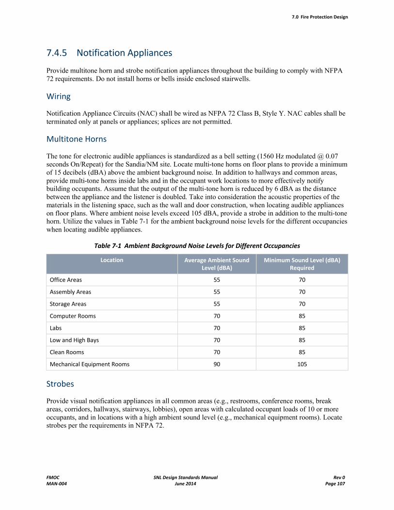
7.0 Fire Protection Design
FMOC SNL Design Standards Manual Rev 0MAN-004 June 2014 Page 107
7.4.5 Notification Appliances
Provide multitone horn and strobe notification appliances throughout the building to comply with NFPA 72 requirements. Do not install horns or bells inside enclosed stairwells.
Wiring
Notification Appliance Circuits (NAC) shall be wired as NFPA 72 Class B, Style Y. NAC cables shall be terminated only at panels or appliances; splices are not permitted.
Multitone Horns
The tone for electronic audible appliances is standardized as a bell setting (1560 Hz modulated @ 0.07seconds On/Repeat) for the Sandia/NM site. Locate multi-tone horns on floor plans to provide a minimum of 15 decibels (dBA) above the ambient background noise. In addition to hallways and common areas, provide multi-tone horns inside labs and in the occupant work locations to more effectively notify building occupants. Assume that the output of the multi-tone horn is reduced by 6 dBA as the distance between the appliance and the listener is doubled. Take into consideration the acoustic properties of the materials in the listening space, such as the wall and door construction, when locating audible appliances on floor plans. Where ambient noise levels exceed 105 dBA, provide a strobe in addition to the multi-tone horn. Utilize the values in Table 7-1 for the ambient background noise levels for the different occupancies when locating audible appliances.
Table 7-1 Ambient Background Noise Levels for Different Occupancies
Location Average Ambient Sound Level (dBA)
Minimum Sound Level (dBA) Required
Office Areas 55 70
Assembly Areas 55 70
Storage Areas 55 70
Computer Rooms 70 85
Labs 70 85
Low and High Bays 70 85
Clean Rooms 70 85
Mechanical Equipment Rooms 90 105
Strobes
Provide visual notification appliances in all common areas (e.g., restrooms, conference rooms, break areas, corridors, hallways, stairways, lobbies), open areas with calculated occupant loads of 10 or more occupants, and in locations with a high ambient sound level (e.g., mechanical equipment rooms). Locate strobes per the requirements in NFPA 72.
7.0 Fire Protection Design
FMOC SNL Design Standards Manual Rev 0MAN-004 June 2014 Page 108
Emergency Responder Multitone Horn/Strobe
At the main entrance(s) to the building, provide a weatherproof multitone horn/strobe appliance on the exterior wall of the building that is readily visible to emergency responders and Security patrols for signaling when the building fire alarm system is in an ALARM condition.
Zoning
The boundaries of notification appliance circuit zones shall be coincide with building outer walls, building fire or smoke compartment boundaries, floor separations, or other fire safety subdivision. NAC zones may contain any combination of multi-tone horns and strobes. Initially load each NAC zone with appliances that do not exceed 80 percent of the available NAC amperage to permit later addition of notification appliances to the circuit. For NAC appliances powered from the FACP, indicate on the floor plans the NAC output or zone number for each appliance (e.g., NAC1, Z-2). For NAC appliances powered from NAC power supplies, indicate on floor plans the power supply identifier and output number (e.g., PS1-4, PS2-1).
7.4.6 Drawing Requirements – Intelligent Fire Alarm System
For new intelligent fire alarm system designs, the A/E must provide fire alarm floor plans indicating the location of the following equipment:
Fire Alarm Control Panel
Fire suppression release panels
Air-sampling control system panels
HVAC control equipment/panels requiring interface with fire alarm system for equipment shutdown.
Smoke removal control panels requiring interface with fire alarm system for equipment activation.
Fire/smoke dampers requiring interface with fire alarm system.
Handicapped-accessible phones requiring interface with fire alarm system.
Fire doors requiring interface with fire alarm system to release (close) doors during an alarm event.
User equipment requiring interface with the fire alarm system.
Location of the automatic sprinkler system Post Indicator Valve.
The fire alarm installer will use these drawings to generate shop drawings for the design of a complete fire alarm design/build package.
The A/E shall provide panel schedules indicating the 120 VAC branch circuit supplying power to the FACP.
7.4.7 Drawing Requirements – Conventional Fire Alarm System
For modification to a conventional fire alarm system, provide plans indicating the location of the following equipment:
Fire Alarm Control Panel
7.0 Fire Protection Design
FMOC SNL Design Standards Manual Rev 0MAN-004 June 2014 Page 109
Annunciators
Initiation devices
Notification appliances
NAC power supplies
Fire safety function equipment requiring connection to fire alarm system (e.g., magnetic door holders, HVAC fan shutdown equipment, fire/smoke dampers, elevator recall/shutdown).
Ancillary panels (e.g., air sampling control panels, fire suppression release panels).
Post Indicator Valves and other equipment located outside building connected to fire alarm system.
Revise the existing floor plans and building riser elementary wiring diagrams as required to reflect the modifications being made to the conventional fire alarm system Initiation Device Circuits (IDCs) and Notification Appliance Circuits (NACs).
Provide panel schedules indicating the 120 VAC branch circuit supplying power to the FACP and NAC power supplies.
Utilize the guidance and requirements in the Facilities CADD Standards Manual and as specified elsewhere in this Design Manual for the preparation of the following drawings to delineate the fire alarm system design.
7.4.8 Calculations
Provide amperage load and voltage drop calculations for each Notification Appliance Circuit. The amperage load for each NAC shall not exceed 80 percent or the rated load to permit later notification appliance additions to the circuit.
7.4.9 Fire Alarm Systems in Temporary Structures
New fire alarm system installations in temporary structures (e.g., mobile offices, T-buildings) with occupants shall utilize an addressable fire alarm control panel designed and installed per the requirements in this section of the Design Manual and the Construction Standard Specification Section13852,"Intelligent Fire Alarm System." For occupied temporary structures that are not physically connected to other similar structures and have an occupant load of less than ten people, provide commercial-grade 120 VAC photoelectric smoke detectors with an audible base, spaced throughout the structure according to the manufacturers recommendations, to notify occupants to evacuate the structure. If the temporary structure(s) are located in close proximity to a permanent building containing a fire alarm system, install a fire alarm system in the temporary structure(s) and connect to the building fire alarm control panel.
7.4.10 Coordination with Sandia
Contact the designated Sandia Fire Protection Engineer to obtain a fire alarm control panel schedule detailing the system configuration when modifying an existing fire alarm system.
8.0 Mechanical Design
FMOC SNL Design Standards Manual Rev 0MAN-004 June 2014 Page 110
8.0 Mechanical Design
8.1 Introduction
The primary objective of these guidelines is to achieve consistency and accuracy in mechanical facilities engineering design through awareness and standardization. These guidelines are general in nature and shall be supplemented by the applicable codes, standards, and guides referenced in this manual. Specific conditions outlined in the project-specific Design Criteria take precedence over these design guidelines.
For general requirements associated with all phases of the project, see Chapter 2, General Design Standards and Procedures. For individual project requirements see the Design Criteria.
For standard product specifications, refer to the applicable section in the Facilities Construction Standard Specifications. Where manufacturers are specifically called out, the purpose is to indicate the desired features and associated level of quality.
As a minimum, all new construction shall conform to the International Code Council (ICC) group of codes. These building code requirements shall be supplemented in a graded manner with additional safety requirements associated with the identified facility hazards. Base design decisions on the lowest life cycle cost of the system.
8.2 Construction Drawings
8.2.1 Drawings Required
To illustrate the scope of a project, an approximate list of the plans and/or drawings required is presented in the Design Criteria for each discipline. Additional drawings may be suggested. Check the Facilities Standard Drawings for applicability to project. Refer to the Facilities CADD Standards Manual for specific CADD standards and processes. The following is a list of plans and/or drawings required for a typical job. (Note: Sandia/NM follows the Uniform Drawing System [UDS] for numbering drawings.) The UDS discipline designators are listed for common systems:
1. Exterior Utilities: Includes but is not necessarily limited to new and existing yard plans showing district steam, condensate return, exterior chilled water, natural gas, fuel oil, special waste disposal system, etc. Other utilities are listed in Chapter 3.2, Construction Drawings. The UDS discipline designators are ‘WG'-Natural Gas, ‘WM'-Steam & Condensate, ‘WH'-Chilled Water.
2. Plan and Profile: Drawings of new site utilities.
3. Interior Plumbing Layout: Show domestic hot and cold water, non-potable water, sewer, vents, drains, lab waste and vents, pressure drains, rainwater leader, and storm drains. Use an isometric diagram to show the sewer, vents, drains, and pressure drains. Use a separate isometric diagram to show the domestic hot and cold water.
4. Interior Gas and Process Gas Plan(s): Show compressed air, nitrogen, natural gas, vacuum, process gases, gas bottle racks, etc. Use a separate Piping Schematic drawing to show all gasses. The UDS discipline designator is ‘DJ'.
5. HVAC Piping Plan(s): Show heating water, pressurized steam and condensate return, tower water, fuel oil, chilled water, condensate drains, or other type of distribution system. In areas where the HVAC piping becomes involved, or where piping is overlaid on the plan, use above-
8.0 Mechanical Design
FMOC SNL Design Standards Manual Rev 0MAN-004 June 2014 Page 111
ceiling and below-ceiling plan(s), and use additional sections, details, or piping schematics for clarification. The UDS discipline designator is ‘MP'
6. Process Liquids Plan(s): Show de-ionized water, process chilled water, hydrochloric acid, process oil systems. In areas where piping becomes involved, or where piping is overlaid on the plan, use additional sections, details, or piping schematics for clarification. The UDS discipline designator is ‘DP'
7. HVAC and Exhaust Duct Plan(s): Show all air distribution, exhaust handling equipment, ductwork, hoods, diffusers, fittings drawn to scale and thoroughly dimensioned. Provide isometric and/or sectional details where the layout becomes complex. Provide separate HVAC and Exhaust Duct plans for extensive exhaust systems. The UDS discipline designators are ‘MP'-HVAC' and ‘MJ'-Exhaust.
8. Separate Roof Plan: Show all roof-mounted equipment, vents, special exhausts, catwalks, etc.
9. Flow Diagram: Schematically shows all heat-transfer processes involved. Show exhaust systems; indicate each source of exhaust, room number, design flow rates, riser flow rates, fan flow rates, dampers, and all other components.
10. Riser Diagram: Show all piping and air handling systems in buildings other than single- story buildings. Key each riser to the appropriate plan.
11. Detail Drawings: Drawings for the above items, showing sections and details. Do not present details and sections on the plan sheets. Include details of security barriers (mesh or rigid bars) installed in ductwork.
12. Control Drawings: Create Control Plans Drawings, Diagrams, Sequence of Operations, Panel Details, Equipment List, and Ladder Diagrams. Group the entire set of controls drawings together in a separate discipline with the UDS designator ‘MI'. On plan drawings, show the location of each item of control equipment, a scale of 1/8 inch per foot or smaller is suggested for most areas of buildings to allow better coordination of the various items in the system drawings. Scales of ½ or ¾ inch per foot may be required in congested equipment rooms. Provide schematic diagrams referring to all control functions and actions. The control diagram shall show control components on a flow diagram with the control piping or wiring in heavy gauge lines. In addition, show the associated heat transfer items such as fans, ductwork, dampers, pumps, coils, pipes, and valves, in light gauge lines such that the total system operation can be determined from the diagram. Provide Sequence of Operations that fully describes the operation of all controlled systems in all modes of operation. (See Chapter 8.23, Controls, for further guidance on controls definition.) Create a layout schedule of panel control devices using an Excel spreadsheet as a format. (See FCS Standard drawing MI5001STD for further guidance.) Because the Facilities Control System (FCS) is unique, the required drawings are listed with the system description. Criteria listed above, applicable to the FCS components, will hold. For reference, utilize FCS Standard drawings; MI5001STD, MI6001STD, MI6002STD. See Chapter 8.23.1, Facilities Control Systems, for additional information for FCS.
13. Equipment Symbols and Schedules: Group these together on a special drawing(s) rather than scattering them throughout the set. Start the equipment schedules in the upper left hand corner of the drawing. Use Sandia/NM standard format and symbols. Do not duplicate numbers.
8.2.2 Piping Drawings
Generally, one-line drawings are satisfactory for designating piping. In certain instances where piping is complex and crowded with other piping or equipment, to-scale, two-line drawings are required to
8.0 Mechanical Design
FMOC SNL Design Standards Manual Rev 0MAN-004 June 2014 Page 112
ascertain that all items will fit without interference (for example, the rising screw on an outside screw and yoke must have adequate clearance when the valve is open). Provide pipe elevations and/or sections for pipes that cross in the plan view.
8.2.3 Schedules
Where the same information is repeated several times, provide a complete, well-arranged schedule (for example, traps and coils could be put in one schedule, complete with capacities, pressure drops, temperatures, etc.). Group schedules together on a drawing(s) adjacent to the equipment list sheet(s) rather than scattering them throughout the set of drawings. Use a standard, sequentially numbered symbol for each item. When scheduled items share a common description, a letter can be appended to the symbol number (e.g. 15a, 15b, 15c, etc.)
8.3 Access and Layout
8.3.1 General Requirements
In general, provide approximately 8 percent of the gross area of the building to house mechanical equipment (fans, compressors, chillers, pumps, electric motor control center, etc.). This area will allow for installation and maintenance of equipment. The following guidelines should be followed for the mechanical equipment room:
The aspect ratio of the room should not exceed 3 to 1
Indicate tube pulling space for boilers, chillers, and heat exchangers
Verify that equipment can be installed during construction
Provide access to remove equipment that has a relatively high rate of failure
Where feasible, do not install piping or ductwork below 7 feet above the finished floor where passage is required.
Indicate coil removal and filter access space for air handler units.
Locate items needing periodic repair, adjustment, or lubrication where they can be accessed from a standing position. Lay out equipment rooms to allow for 36 inches of clear floor and aisle space around all major equipment. Arrange or provide space so tube bundles can be withdrawn or major items of equipment can be replaced without repiping or relocating other equipment. Where necessary, provide areaways and/or removable wall panels for access. Anticipate and eliminate head-bumping or tripping hazards. On the structural drawings, accurately detail and locate sleeves through walls and floors. Field welding or cutting structural steel is forbidden. Lay out manholes so personnel can exit quickly. Where possible, locate a manhole cover over the ladder.
Size and ventilate workspaces to provide adequate working conditions for maintenance personnel. Clearly state mounting heights for wall-hung items, or provide elevations of crowded walls, particularly where electrical and structural items are also involved. Arrange pipes in pipe space/chases to allow a mechanic to conveniently get into the pipe space and work on a section or part of the piping.
Inform the architectural and structural designers of all ladders, catwalks, access doors, and special structural equipment needed for the proper maintenance of mechanical equipment.
8.0 Mechanical Design
FMOC SNL Design Standards Manual Rev 0MAN-004 June 2014 Page 113
The space above suspended ceilings shall be adequate to run ductwork and piping. Normally allow a 3-foot-minimum clearance from the top of light fixtures to the bottom of construction for the installation of ductwork and piping.
Provide a minimum 6-foot-edge clearance for roof-mounted equipment unless pipe guardrails are provided.
Provide access doors to gypsum board ceilings and other restricted spaces where mechanical equipment is located.
8.3.2 Security Requirements
All Security Area and VTR boundaries must have consistent penetration resistance. Openings in the boundary of such areas must be protected to DOE Order requirements. Examples of such openings are heating, ventilating, and air conditioning ducts, air intakes, exhaust fans or ducts; and doors, crawlways, tunneled areaways, and sewers.
Where the mechanical designer is responsible for the design and placement of such items, communicate the information to other responsible consultants who will take the necessary electrical or structural steps to ensure compliance with security requirements. Ensure that these steps have not introduced excessive resistance or other problems into the original design. Recalculate and modify as required. See Chapter 11 for specific requirements.
8.4 Modular Design
Design mechanical systems in the most flexible manner possible, since changing programs and occupants result in changing needs. Do not oversize systems dramatically. Arrange diffusers, registers, sprinkler heads, and other semi-permanent features on the module system for future flexibility of walls and partitions. Contact the Sandia/NM systems architect for additional information on the module system.
8.5 Equipment Selection–General
Because the selection of mechanical equipment is involved, provide copies of calculations and standard or actual conditions used for the selection of all mechanical equipment, even when following the manufacturer's procedures. Make adjustments to manufacturer's altitude rating as required for the Sandia/New Mexico altitude of 5,500 feet. Comply with ASHRAE Std. 90.1, Energy Standard for Buildings Except Low-Rise Residential Buildings, for minimum equipment efficiencies.
A brief but complete description of equipment shall appear on the equipment list drawings. The designer shall locate and describe one manufacturer's model that meets design requirements. Present the manufacturer's complete catalog number and all rating and performance information. Generalities in selection are unacceptable. Provide additional special specifications to equipment schedules to more fully describe complicated equipment. Use performance specifications that will ensure a quality product. Key mechanical item numbers to the plans and elevation drawings.
A partial load schedule, in 10-percent steps, will be established, and the manufacturer's actual performance data shall be listed for all variable-capacity, heat-transfer equipment.
All equipment assemblies requiring line electrical power shall have a local power disconnecting means rated for the service. Refer to paragraph 9.3.5 for requirements.
8.0 Mechanical Design
FMOC SNL Design Standards Manual Rev 0MAN-004 June 2014 Page 114
Whenever mechanical equipment is specified as a complete unit with electrical components such as motors, VFCs, disconnects, lighting and wiring, the associated electrical specifications shall be referenced to insure that these components meet those specifications as well.
8.5.1 Air-Handling Units
Fans and blowers for cooling and heating equipment are generally large-diameter, low-speed, low-horsepower (HP) and capable of maintaining the required system static pressure. Air-foil fan blades are preferred but backward inclined may be acceptable. Select and specify extra-heavy-duty, long-life bearings (minimum 50,000 hours) from standard bearing manufacturer charts provided by the fan manufacturer for the maximum published speed and HP rating of the fan. Select load-limiting (backward curved) wheels whenever practicable. High-velocity systems are discouraged, but if used, select fans that minimize surging and air noise. Present calculations, including temperature and altitude corrections. Select fans to operate on a stable portion of the curve. Discourage the use of small-diameter, long shaft fans except in small packaged equipment.
8.5.2 Motors
The minimum energy efficiency requirements for all single-speed, National Electrical Manufacturers Association (NEMA) Design B induction motors having nominal speeds of 1200, 1800, or 3600 rpm with open, drip-proof (ODP), or totally enclosed fan cooled (TEFC) enclosures, 1 HP or more shall comply with the requirements of table 10.2 of ASHRAE 90.1-1999 (matches NEMA Standard MG 1-1998). Motors for driven systems greater than 5 HP that operate for long periods of time (>3600 hours/year) may justify efficiencies which exceed the minimum requirements ("premium efficiency motors") and should be evaluated for simple payback on new or retrofit installations.
Annual savings (S) = 0.746*BHP*$/kWh*annual hours operation* [(100/effA) – (100/effB)], where effB is the efficiency (percent) of the higher efficiency motor.
An electric motor should be considered as always being connected to a driven machine, with specific operating characteristics, which dictate the starting and running load of the motor. As such, the motor selection is based on many factors, including the requirements of the driven equipment, service conditions, motor efficiency, power factor and initial cost. The driven system efficiency is the combination of the efficiencies of all the components of the system, e.g., the fan efficiency, the power transmission (belts), the air distribution system, and the motor controllers (such as Variable-Frequency Controllers [VFCs]).
Provide 3-phase motors for 1 HP and above. Provide across-the-line starters on smaller motors, and reduced voltage, auto-transformer, or other inrush, current-limiting, starter types on motors greater than 25 HP, or where system capacity or mechanical requirements indicate the need on smaller motor applications. Select motors with a sufficient rating for the duty they are to perform and not to exceed their continuous HP rating, including service factor, when the driven equipment is operating at its greatest HP. Coordinate starting and running characteristics with the driven machine and the motor control equipment. Motor enclosures shall be ODP for indoors dry locations and totally enclosed or totally enclosed fan-cooled for outdoor or wet locations, except where special conditions require otherwise.
Single-phase motors 1/8 HP and smaller shall be shaded-pole or permanent split capacitor; those larger than 1/8 HP shall be capacitor-start. Polyphase motors shall comply with NEMA Design B, unless other characteristics are required by the driven machine or the speed controller. Design motors for continuous service at 104°F (40°C) ambient temperature. Motors shall operate at full capacity, with a voltage
8.0 Mechanical Design
FMOC SNL Design Standards Manual Rev 0MAN-004 June 2014 Page 115
variation of plus or minus 10 percent of the nameplate voltage. Consider high-efficiency and premium-efficiency motors where loading and continual use may result in significant energy savings.
Consider VFCrs where motor speed requirements vary widely during normal operation. Solid-state, variable-frequency units are recommended for smaller HP motors. In all cases, select the motor in accordance with the drive manufacturer's recommendations to ensure a coordinated system and to avoid damage to the motor. In particular, induction motors driven by a VFC shall have provisions for rotor shaft grounding and VFC output filtering so as to prevent bearing fluting from inductive buildup and discharge.
8.5.3 Pumps
Where circulating pumps are used in open systems such as cooling towers, install a suitable straining device (basket-type for base-mounted pumps) in suction lines and provide for easy removal to allow for cleaning. Connect all circulating pumps to the piping system through flexible couplings. Never connect a 90-degree elbow directly to the suction opening of any pump.
8.5.4 Air Filters
Air handlers shall be designed to accept bag type filters. Preferred size for filters is 24 inches x 24 inches x 15 inches deep, and the preferred media is fiberglass. Filter frame assemblies shall be specified such that there will be no leakage around the filters or filter bank. Farr Type 8 front-loading filter frames or Farr 3P Glide/Pack side loading frames, or equal, should be specified. Cartridge filters and slide rack frames are permitted in fan coil units and small roof top air handler units. Filter banks shall be sized for no greater than 500 feet per minute face velocity.
General office area and light lab air handling equipment will use 50 percent efficient bag filters. Process, manufacturing, and special use area filter efficiencies will be determined by the project need. Air filters shall be rated either as Class 1 or Class 2 in accordance with UL900 Standard for Safety Air Filter Units and NFPA 90A.
Use only Class 1 filters in clean room applications. Nuclear Grade HEPA filters shall be listed under UL 586, Standard for Safety Test Performance of High Efficiency Particular Filter Units.
8.5.5 Humidifiers
Avoid humidifiers using a standing water reservoir. Equip all humidifiers with a drain-down, bleed-off, and overflow. Humidifiers supplied with non-potable water shall have a demineralizer tank installed to reduce scale build-up.
8.6 Plumbing Design
8.6.1 Design Conditions
Water main pressure is 60 to 110 pounds per square inch gauge (psig). Maximum water pressure varies depending on the location within the site. Consult with the systems engineer for design water pressures. Natural gas main pressure is 20 psig.
Flush valves shall have a 25-psig-minimum residual pressure; all other fixtures shall have a residual pressure of 15 psig minimum.
8.0 Mechanical Design
FMOC SNL Design Standards Manual Rev 0MAN-004 June 2014 Page 116
Water velocities shall not exceed 10 feet per second.
8.6.2 Potable versus Non-potable Water Connections
Supply Potable Water:
To all plumbing fixtures except for fixtures located within a fume hood.
To evaporative coolers and air washers, and provide an air gap between the supply and the flood rim.
To landscaped (trees, lawns, shrubs, etc.) areas, and provide a vacuum breaker after the last valve (do not install shutoff valves downstream of a vacuum breaker).
To eyewash and safety showers.
To dishwashers and ice machines, and provide an air gap.
To sinks with hose connections, yard hydrants, and hose bibbs. Provide with vacuum breakers.
Supply Non-Potable Water:
To fume hoods
To de-ionizing or de-mineralizing water systems
To any connections provided in laboratory space for future use.
To make-up water connections to circulated water systems.
Always consider the use of a distributed Non-Potable Water (NPW) system for multiple users as opposed to a Backflow Preventer (BFP) at each point of use. Make the decision based on life cycle cost. Refer to Chapter 7.3, Fire Protection Backflow Preventers, for backflow prevention requirements.
Provide signs at fume hood faucets and any outlet on the non-potable water system stating: "Danger –Non-potable Water."
8.6.3 Calculations Required
Hot and cold water systems:
Demands in fixture units or gallons per minute
Pipe sizing
Shock absorber sizing
Water heater storage capacity sizing
Hot water expansion tanks.
For buildings with 50 or more occupants, base the selection of domestic water heaters on an economic balance of the maximum daily demand, the maximum hourly demand, the first cost and operation cost, and the availability and cost of fuel.
Sewer, vents, and drain lines:
Load capacities (fixture units) to determine sizing
Absorption rates for drain fields and seepage pits established by actual field percolation tests.
Gas supply system:
8.0 Mechanical Design
FMOC SNL Design Standards Manual Rev 0MAN-004 June 2014 Page 117
Capacity used to size from tables in International Fuel Gas Code. (See Chapter 3 for exterior gas piping.)
Roof drains and piping:
Rainfall rates (Sandia/NM=2 inches per hour)
Flow rates
Pipe sizing.
Backflow Preventers:
Sizing shall account for the head loss through the device at typical flow rates not to exceed 7.5 feet per second through the device.
8.6.4 Piping Materials and Labeling
Refer to Facilities Construction Standard Specification Sections 15051, Piping Systems, and 15401, Plumbing.
For selection of drainage piping in buildings that use corrosive chemicals, coordinate with the user to determine what corrosive chemicals will be drained, the temperature range of the effluent, and the amount of their dilution. Consult the Sandia Materials group or Environment, Safety, and Health when a possibility exists for a combination of corrosive chemicals to go into drains, and to determine the need for a neutralizing tank as a substitute for, or in addition to, corrosive drainage piping.
Construction Standard Specification 15401 specifies materials and installation requirements for "Laboratory/Process/Acid Waste and Vent systems that apply to systems so designated on the drawings. While no single material is capable of handling every chemical, the specification is based on either Polypropylene or PVDF with electric fusion joints. These materials are capable of withstanding corrosion from the widest number of chemicals but they may not be satisfactory for all conditions. The mechanical designer shall determine the appropriate material to be used based on the chemicals and their concentration, pressures and temperatures, system life and cost.
Identify piping with self-adhesive labels. Refer to Facilities Construction Standard Specification Section 15050, Basic Mechanical Materials and Methods.
8.6.5 Plumbing Fixtures
Standard plumbing fixtures (toilets, drinking fountains, sinks, etc.) are listed in Facilities Construction Standard Specification Section 15401, Plumbing. The designer shall specify special laboratory fixtures to meet customer's requirements. Flushometer valves for urinals and water closets shall be specified as Sloan or Zurn without exceptions.
8.6.6 Backflow Preventers
Design Conditions
Backflow prevention (BFP) assemblies are required to prevent cross-connection contamination between potable water systems and non-potable, potentially polluted, or potentially contaminated systems, such as drainage systems, soil lines, and chemical lines.
8.0 Mechanical Design
FMOC SNL Design Standards Manual Rev 0MAN-004 June 2014 Page 118
BFP assemblies are required to be approved by Sandia/NM and the Foundation for Cross-Connection Control and Hydraulic Research, University of California, and the International Association of Mechanical and Plumbing Officials.
Keep the number of BFP assemblies to a minimum through connection of non-potables on a common system.
Apply the devices in accordance with the following general guidelines:
Atmospheric vacuum breakers must be installed on the discharge side of the last shutoff valve and a minimum of 6 inches above the highest overflow level.
Vacuum breakers must be installed a minimum of 12 inches above the highest piping or outlet downstream of the device and must not be used where backpressure may occur. Discharge pressure should be maintained above 5 psig at all times.
Double check-valve backflow preventer may be used if there is a possibility of backpressure, or if a low or nontoxic hazard exists.
Use a reduced-pressure double check valve if there is a possibility of back pressure and a toxic hazard exists.
Installation for the above backflow preventers shall provide the following:
Positive drain for all discharges to an appropriate point with positive air gaps, as required
Easy accessibility for testing and maintenance
Protection from freezing
Proper support when necessary
Provisions for excessive pressure or thermal expansion downstream
Placement between 12 inches and 60 inches above finished floor level.
Configure the device to provide protection for high-hazard service with necessary check valve, relief valve, test cock, and isolation valve to conform to all codes having jurisdiction.
Refer to Chapter 7.3, Fire Protection Backflow Preventers, for sprinkler system backflow prevention requirements.
8.6.7 Calculations Required
Sizing shall account for the head loss through the device at typical flow rates not to exceed 7.5 feet per second through the device.
8.6.8 Plumbing–General
Provide building water pressure regulators for any building where the water system pressure is over 80 psig.
Provide building water flow meters for all facilities. Where possible, specify a meter which can report through the FCS system and provide a communication dataway to the device.
Provide suitable facilities for emergency quick drenching or flushing of the eyes and body in workplaces where occupants may be exposed to injurious, corrosive material. For all installations, involve the
8.0 Mechanical Design
FMOC SNL Design Standards Manual Rev 0MAN-004 June 2014 Page 119
occupants' organization's Industrial Hygienist in selecting the type and location(s) for emergency eyewash and shower equipment. Generally, these will be:
Positioned 100 feet or less from the hazard,
Located in accessible areas that can be reached in 10 seconds or less,
Labeled with a highly visible sign, and
Illuminated with proper lighting (coordinate with electrical designer).
All eyewashes and safety showers shall meet the American National Standards Institute (ANSI) Z358.1 standard requirements. Hand-held drench hoses may provide support for emergency shower and eyewash units, but shall not replace them. Due to the infrequent of use of safety showers, floor drains generally are not required. Showers can be tested with a curtain and bucket. Unless water is supplied directly from outdoors, tempered supply water also is not required. Refer to Facilities Construction Standard Specification Section 15401, Plumbing.
Water lines with solenoid valves, flush valves, or other quick-closing devices should be fitted with an accessible, valved and sealed shock chamber to absorb water hammer. Lengths of pipe that are capped to form air chambers are unacceptable.
Install wall hydrants 18 inches above grade on each major outside building surface, not to exceed 100 feet apart. Do not cast hydrants into masonry. Incorporate a vacuum breaker at each wall hydrant. Locate hydrants to insure that they will not be subject to freezing.
Do not cast any piping within the structure into concrete, except cast-iron sewers.
For future extension show service piping such as gas, compressed air, and domestic water (where applicable), with plugged tees instead of elbows. Provide isolation valves for ease of isolating sections of piping for future modifications without the need to shut down most of the system.
Plumbing accommodations in government facilities shall conform to 28 Code of Federal Regulation, Part 36, Nondiscrimination on the Basis of Disability by Public Accommodations in Commercial Facilities. See Chapter 6.7, Accessibility Requirements, for further information.
Install a minimum of one floor drain per room in toilet rooms, darkrooms, janitor closets, and equipment rooms. Install adequate floor sinks, wherever needed, to take indirect wastes. Provide steam and valve pits with a French drain, 2 feet in diameter by 5 feet deep, filled with 1/2- to 1-inch clean, graded gravel. Coordinate with the structural drawings to ensure that floors are pitched downward toward all floor drains. Floor drain gratings shall be of heavy-duty construction and made from nonferrous material. Floor drain bodies shall be galvanized. Trapped floor receptacles shall be primed. Do not specify trap primers that rely on pressure fluctuations in the piping to activate the primer. Timed solenoid valves have been the most useful device for priming traps.
Do not connect floor drains to the storm drain system. The design team shall ensure by visual inspection, drawing search, and/or dye testing that plumbing connections are made to appropriate sanitary sewer piping. Do not make piping connection that would result in the flow of non-storm water to the storm drain system. Storm water is defined as those flows that result from atmospheric precipitation which have not been confined in any way (see Sandia/NM Environment, Safety and Health (ES&H) Manual). Consider the use of "water harvesting" for the discharge of roof drains on new facilities. Refer to Section 3.6 –Drainage Requirements.
8.0 Mechanical Design
FMOC SNL Design Standards Manual Rev 0MAN-004 June 2014 Page 120
Detail roof drains in cross section and incorporate a suitable removable strainer or gravel guard, seepage pan, and clamping device. Connect the roof drains to the storm drainage system. Insulate roof drain piping in ceiling spaces.
Space sewer cleanouts to grade no further than 50 feet in buildings. Terminate each branch run in a full-size cleanout. Show sewer cleanouts on both the plan and isometric drawings. Locate cleanouts so a power-driven snake can be used without the need to relocate.
Make extensive use of re-venting, where practicable, to minimize roof penetrations. Hubless cast-iron pipe and fittings are acceptable above grade.
8.7 Heating/Cooling/Ventilation and Energy Calculations – General
Heating and cooling load calculations and energy and economic analysis shall be performed using Trane Trace 700 software. Analysis shall be performed early in the conceptual stages of the design to evaluate system size and compare alternatives. The analysis should also be performed for the as-designed conditions reflecting the construction, layout, and system configuration. Analysis of alternatives shall be based on life cycle cost analysis and consider first cost, maintenance, and energy cost as well as the project budget. The latest utility cost shall be obtained from the system engineering organization.
Provide ventilation to all occupied spaces to meet the requirements of ASHRAE Standard 62 ‘Ventilation for Acceptable Indoor Air Quality' latest addendum. Describe in the design analysis the procedures used and the necessary controls to meet the requirements.
Calculations shall be submitted as a part of the Design Analysis that include the following:
Narrative – Describing the type of construction, alternatives analyzed, assumptions for internal loads, airflows, construction, and schedules and supporting documentation.
Drawings, sketches and schematics – Fully describe the zoning layout, system configuration, and construction types as referred to in the program.
Reports – Provide the reports necessary to document the design decisions.
Archive Files - FILENAME.TRC – The project file that contains all the information you entered into the program, including project, weather, room, system, zone, and load parameter information and any Project Templates that you used for entering room information. It also contains the results of the design calculations. LIBRARY.DB (optional) - The library database that contains all the information from the libraries that the program uses (Weather, Schedules, Construction Types, Glass Types, Materials, Internal and Airflow Loads, and Shading), plus all of the Global Templates.
NOTE You only need to archive this database if your project file uses "custom" library members, e.g. a library member that you created.
Provide calculations to support the ventilation levels the system and individual spaces.
8.0 Mechanical Design
FMOC SNL Design Standards Manual Rev 0MAN-004 June 2014 Page 121
8.8 Heating Design
8.8.1 Design Conditions
Unless otherwise specified in the Design Criteria, use the tabulated weather data tables in the American Society of Heating, Refrigeration, and Air Conditioning (ASHRAE) Fundamentals volume per the following: Laboratory Occupancy 99 percent column, Personnel Comfort 97.5 percent column for outdoor temperatures.
Infiltration, except where exceeded by ventilation, should be taken into account by using the air-change method outlined in the ASHRAE guide. Pressurize all structures to approximately 0.03 inches of water to minimize infiltration, except where noted in the Mechanical Design Criteria. The minimum outside air required to provide ventilation for each zone shall be in accordance with the latest edition of ASHRAE Standard 62. Include an additional air allowance for pickup when sizing boilers and converters. Systems shall not be additionally oversized unless otherwise noted in the Design Criteria.
Do not take credit for the heating contribution of light fixtures when sizing heating equipment for buildings that will be partially occupied during nonwork hours. Full credit will be taken for buildings that are occupied during working hours only.
In Tech Area I at Sandia/NM, use district steam only when life-cycle cost effective considering complete Steam Plant shut-down by the year 2012. In general, systems should be planned to migrate to decentralized hot water boilers. Use gas fired hot water boilers as the primary source of heat for new and renovated buildings. Provide proper zoning so areas will not overheat as the result of winter sun and/or interior room heat that affects only part of a zone.
Design heating water systems with 180°F maximum supply temperature and a 20-40°F drop.
Provide a design for all piping supports for above- and below-grade steam, condensate, and hot water piping. Include in the design the locations of supports, support details, and specifications for piping restraints, piping guides, expansion loops, and expansion compensation devices. Piping outside the Steam Plant (building 605) shall be designed and constructed to meet ANSI B31.3, Process Piping. Piping within the Steam Plant shall be designed to meet ANSI B31.1 Power Piping.
8.8.2 Calculations Required
Heating Systems
Heat loss by rooms, zones, and buildings
Capacity of the distribution systems
Heat-generating and heat-transfer equipment
Hydronic calculations
Pump sizing
Fan sizing
Thermal expansion of steam, condensate, and hot water piping
8.0 Mechanical Design
FMOC SNL Design Standards Manual Rev 0MAN-004 June 2014 Page 122
Fouling Factors
Present calculations to show the effects of fouling factors on either side of heat-exchange surfaces.
8.8.3 Piping Materials
Refer to Facilities Construction Standard Specification Section 15051, Piping Systems.
8.8.4 Heating System – General
Where possible, install local gas fired hydronic heating systems.
Size steel boilers by matching the net Steel Boiler Institute output ratings, corrected for altitude, with the calculated heat loss for the structure. Use net IBR ratings (Institute of Boiler and Radiation Manufacturers on Hydronics Institute) for cast-iron boilers or 30 percent allowance for pickup on other types of boilers and converters.
Boiler selection shall be by life-cycle cost and shall include the significantly different life expectancy and efficiencies of boiler types. Estimates of seasonal efficiency shall consider the effect of type of control, (on/off, high/low/off, fully modulating), number of boilers, and oversizing. Leave spare floor space for future expansion.
Use an outdoor reset water temperature control through the FCS to provide hot water supply temperatures according to outside air conditions without overheating.
In heating water systems, the control scheme shall cause the heating water pumps to operate only when there is a call for heating and to shut down during unoccupied hours. See Chapter 8.23, Controls.
Design all large heating water distribution systems that use a two-pipe, reverse-return primary system. In large buildings, give consideration to a primary and secondary system.
For water treatment requirements for heating water systems refer to the Water Treatment section later in this chapter.
Air vents on exposed hot water lines over 7 feet above the floor shall consist of ¼-inch copper tubing extended down to a petcock located 7 feet above the floor. Vents on hot water lines above ceilings need not extend below the ceiling.
Show flow-limiting devices and isolating valves for each use point. Size the piping so a minimum use of balancing valves will be required. Diverting tees are acceptable, provided the drop in main temperature is taken into account. Make extensive use of insertion test plugs to assist in balancing. Install flow meters or other flow measuring devices to indicate rate of flow in each system and zone. Use flow meters on small systems up to 10 gallons per minute. Use Delta P venturi fittings (less meter) on larger systems. Use a pumped coil for freeze protection on outside air applications.
Give special attention to wind pressure in warm air distribution systems, noting that severe winds are experienced at Sandia/NM. Incorporate features or zoning so the major portion of air will travel to the upwind side of the structure where it is needed most.
Gas-fired heaters shall have double wall vents and 100-percent stainless steel heat exchangers when 100-percent outdoor makeup air is used. Combustion air is not to be taken from the occupied space. Direct-fired makeup air handler units shall not be used without approval of the systems engineer. Direct-fired
8.0 Mechanical Design
FMOC SNL Design Standards Manual Rev 0MAN-004 June 2014 Page 123
makeup units should not be used for makeup air to a chiller plant due to the possibility of vented refrigerant reacting in the gas flame.
Provide electric duct heaters, where required, with a manual and automatic reset, high-limit control, and a differential pressure switch (or other flow sensing device). Stage electric heaters.
8.8.5 Air Emissions Permits
In accordance with Section 17B-Air Permits of the Sandia/NM ES&H manual, fossil fuel-fired equipment will require an air permit for Bernalillo County before construction can begin if one or more of the following conditions exist:
Potential emissions of a regulated air contaminant greater than 2,000 pounds per year
Potential emissions of a regulated air contaminant greater than 10 pounds per hour
Emissions from fossil fuel (e.g., natural gas, Diesel)-fired boilers.
As soon as the mechanical designer has designed the heating system, selected equipment, and determined that any of these conditions are met, the Sandia/NM Project Manager shall be notified of the potential need for an air permit and provided with the specifications of the fossil fuel-fired equipment. Contact the Environmental Programs & Assurance department for questions concerning air emissions and additional details. Obtaining a permit may take up to 180 days.
8.8.6 Boiler Controls
All boilers less that 12.5 MMBTU/hr. input rating shall meet the requirements of ASME CSD-1, ‘Controls and Safety Devices for Automatically Fired Boilers'. Boilers 12.5 MMBTU/hr. and larger shall meet the requirements of NFPA 85.
8.9 Evaporative Cooling Design
8.9.1 Design Conditions
Applications to be considered are as a supplemental source of cooling for office and lab applications; and, should be considered as primary cooling for warehouses, shops not requiring close (plus or minus 5°F) temperature controls, nonresidential-size kitchens, makeup air ventilation units, and mechanical equipment spaces.
Spray pumps shall be located outside of the air stream when used in process exhaust systems and for any air handling system requiring 24-hour, 7-day-per-week operation.
Specify indoor design dry bulb temperatures for spaces air conditioned by adiabatic cooling systems by project-specific criteria. Operating efficiency for adiabatic cooling equipment shall be a minimum of 70 percent. Base the system-installed capacity on the conditioned space peak design cooling load. Do not use an arbitrary air-change rate for design airflow. State adiabatic cooler specifications in terms of air capacity, the entering ambient dry and wet bulb temperatures, and leaving dry bulb temperature.
When evaporative coolers are installed as supplemental cooling in an air handler unit, they should be installed downstream from the chilled water coil and controlled to operate as a first stage of cooling whenever the outside air dew point is below the highest allowable space dew point. The chilled water
8.0 Mechanical Design
FMOC SNL Design Standards Manual Rev 0MAN-004 June 2014 Page 124
valve would then be modulated to maintain the required supply air set point. This setup will allow the use of warmer chilled water temperatures, more frequent use plate & frame heat exchangers, and more efficient operation of chillers.
Consider air duct design, number, and location of coolers, and reliefs of the higher rate of air supply (for two-speed fan operation) to the atmosphere to ensure a satisfactory operating system. Also, consider multi-stage indirect evaporative cooling systems.
8.9.2 Calculations Required
Heat gains by rooms, zones, and building
Capacity of distribution systems
Psychrometric analysis (trace process on chart corrected for altitude)
Heat dissipating equipment.
8.9.3 General
Specify drip-pad coolers on small installations where the use of fan curves is not required in the design. Specify high-efficiency rigid media coolers with stainless steel water sumps on medium and large size systems and where fan curves are needed in the design.
For energy conservation, specify the lightest color available from the manufacturer for the exterior finish coat of the cabinet.
Specify two-speed motors on all fans serving evaporative cooling equipment.
Detail a bleed, overflow, and drain on the piping diagram for each piece of evaporative equipment. Set the bleed amount for 1 gallon per minute per 1,000 cubic feet per minute of air flow. Arrange overflow and drains so fan suction does not empty a trap and thereby allow sewer gases to be pulled into the system. Inactive traps shall not evaporate the water seal with the same result. Discharge the bleed line to a sanitary sewer.
Detail a system for thoroughly draining (without the use of tools) supply-water piping that is subject to freezing. Include a slide damper in the design of small evaporative units. Install a spare set of guideways on the duct or other similar structure to provide for summer storage of the slide damper. When larger units are included and motor-operated dampers are used, the slide damper guideway is installed upstream of the evaporative section. Provide access doors to facilitate working on the evaporative media, the pumps, motors, etc.
8.10 Refrigeration Design
8.10.1 System Selection
Unless specified otherwise in the Design Criteria, analyze all options for providing cooling for new facilities and renovations to existing facilities to determine the option with the lowest life cycle cost. Fully consider impacts to energy efficiency, reliability, flexibility, and maintainability. A number of campus type chilled water distribution systems exist within the tech areas that should be looked at for a source of cooling. The choice of direct expansion (DX) vs. local chilled water vs. campus chilled water systems should be reviewed with the systems engineer during the design phase to insure the system meets Sandia's
8.0 Mechanical Design
FMOC SNL Design Standards Manual Rev 0MAN-004 June 2014 Page 125
long term needs. In all cases avoid the use of small local DX equipment within a building (other than MO and T-buildings) due to high maintenance requirements.
Refer to the Master Chilled Water Plan for the campus chilled water loops. The Campus Chilled Water Loops include:
Tech Area 1 Central Chilled Water System (850/894/890)
Tech Area 1 South Chilled Water System (823)
Tech Area 1 Southeast Chilled Water System (899/726)
Tech Area 1 East Chilled Water System (858N/870)
Tech Area 1 North Chilled Water System
Tech Area 4 Chilled Water System
Connecting to an existing chilled water system is the preferred method for providing cooling if system capacity is available and the distance to run chilled water does not make the life cycle cost unfavorable. Chilled water systems have advantages of higher efficiency, lower maintenance, flexibility to adapt to local cooling loads as facilities are modified, and they can be a source of cooling if a process chilled water system is required. Before connecting to a campus chilled water loop consult with the systems engineer to determine if capacity is available, the type of connection to use, the expected supply water temperature, the temperature difference to design for, and pumping pressure requirements. Supply the systems engineer with annual cooling load profiles and peak design loads for current and future estimated requirements. Most chilled water systems are of the variable flow type requiring VFCs on the pumps and 2-way control valves at the coils. Provide BTU meters for monitoring water flows and cooling loads for each building.
8.10.2 Design Conditions
For calculating building cooling loads, unless otherwise specified in the Design Criteria, use the tabulated weather data tables in the ASHRAE Fundamental Volume per the following: Laboratory Occupancy 0.4 percent dry bulb and 0.4 percent wet bulb column; Personnel Comfort 1 percent dry bulb and 2 percent wet bulb column. Size cooling towers and air-cooled condensers for the maximum actual conditions to which they are subjected.
Unless otherwise mentioned in the criteria, inside design conditions for personnel comfort shall be the 1 percent outdoor design dry bulb conditions, 72°F dry bulb. Comply with ASHRAE 90.1 for sizing of equipment and component. Present other indoor temperatures and humidities that are required for process or sensitive equipment in the Design Criteria. Present complete room-by-room and zone-by-zone heat-gain calculations. In general, pressurize all structures to minimize infiltration.
8.10.3 Calculations Required
Heat gain by rooms, zones, and building.
Capacity of the distribution systems
Heat-dissipating equipment
Hydraulic calculations
Psychrometric analysis (trace process on a chart corrected for altitude)
8.0 Mechanical Design
FMOC SNL Design Standards Manual Rev 0MAN-004 June 2014 Page 126
Compliance within the Code Footprint to the International Building, Mechanical, Plumbing and Fuel Gas Codes for refrigerant quantity limits, as well as any need for a machinery room.
Calculations for normal and emergency ventilation rates of machinery rooms within the design analysis document.
Provide within the Code footprint compliance with the IBC, IMC, IPC, and IFGC for refrigerant quantity limits and any need for a machinery room. Provide calculations for normal and emergency ventilation rates of machinery rooms within the Design Analysis document.
Calculations for sizing chillers and supply-air quantities shall take into consideration both space and building electrical loads. The electrical loads are obtained from the electrical designer, who will determine loading from the electrical drawings and partial loading from the energy schedule in the Design Criteria. Modify the laboratory equipment portion of the full-load quantities to actual loading values by an appropriate diversity factor. Consult Sandia/NM Facilities Engineering to determine this factor. The equipment shall not be sized for future additional capacity or redundancy unless indicated in the Design Criteria.
8.10.4 Piping Materials
Refer to Facilities Construction Standard Specification Section 15183, Refrigeration Systems.
8.10.5 Refrigeration System—General
Show detailed provisions for draining condensed moisture from the cooling coils to a floor drain. Pay special attention to showing how the moisture is collected as it comes off the coil.
For built-up systems, use a control diagram to describe the appropriate safety, temperature, and pressure controls. Each reciprocating compressor shall have a high- and low-pressure cutout, low-oil-pressure cutout, and low-temperature cutout (to prevent freezing of tubes in water chillers). Where capacity reduction is needed at low loads to prevent short cycling, use automatic unloaders and/or properly staged multiple smaller compressors. Where possible, avoid using energy-wasting hot gas bypass designs. Install a time delay to prevent short cycling.
Fit compressors that are 5 hp and greater with an elapsed running time meter.
Heat rejection devices such as air-cooled condensers are preferred, except where size and equipment dictate the use of cooling towers. Select air-cooled condensers at least one size larger than determined bycalculations, with corrections for altitude when the condenser is installed on roofs that experience high temperatures. Specify cabinets for air-cooled condensers with the lightest color available from standard manufacture. Specify a minimum ground clearance of 12 inches for condensers over 3 tons installed on grade. Smaller condensers should be installed on concrete pads or rails at least six inches above grade. Specify hail guards for all exposed condenser coils. Unless required by space or cost restrictions, locate air-cooled condensers away from direct sun exposure and where they will be suitable for operation at low ambient conditions. Pay attention to oil return and where equipment must operate in cold weather. Provisions must be made to guard against low-head pressures and backslugging of liquid (low ambient protection). Where short-cycling or capacity reduction can become a problem provide several smaller compressors. To prevent freeze-up and extend the life of the cooling towers, provide a sump tank on cooling towers being used for year-round cooling. Include an automatic condenser water temperature control to maintain optimum refrigeration equipment operating efficiency. Specify cooling towers constructed of fire-resistant materials.
8.0 Mechanical Design
FMOC SNL Design Standards Manual Rev 0MAN-004 June 2014 Page 127
Air-to-air heat pumps are permitted for T-buildings or mobile offices only or to transfer energy within a building.
Design medium to large chilled water systems using either a two-pipe, reverse-return flow, or oversized mains and with a 10-15°F temperature differential. When a primary-secondary system is designed, additional circulators are required on each secondary loop. Consider variable flow systems with variable speed pumping in systems over 100 tons. In constant flow systems, install flow controllers and heat exchange devices (coils, etc.) in each zone. Although balancing valves are generally not necessary in variable flow systems, they can be useful for troubleshooting problems later. Use Bell and Gossett circuit setters on small systems up to 10 gallons per minute. Minimize the use of balancing valves in variable flow systems.
Refer to Chapter 8.28.2 for water treatment requirements for chilled water piping.
Air vents on exposed chilled water lines over 7 feet above the floor shall consist of ¼-inch copper tubing extending down to a petcock located 7 feet above the floor. Vents on chilled water lines above ceilings do not need extending down to below the ceiling.
Specify Air Conditioning and Refrigeration Institute certified water coils. Size coils for 500 feet per minute maximum face velocity.
Two-way water control valves are preferred over three-way valves, except that a minimum number of three-way valves shall be used to provide the minimum flow needed for chillers. Use series and parallel pumps with automatic controls to limit the valve differential head increase to twice the initial head. Systems with lower heads (60 to 70 feet) shall use parallel arrangement. Systems with higher heads shall use a series arrangement.
Wherever possible, include economy cycle provisions in the system.
Choose refrigeration equipment to comply with the minimum coefficient of performance ratings as listed in ASHRAE Standard 90.1. New equipment should be limited to using refrigerants classified A1 or B1 by ASHRAE Standard 34 and either hydrofluorocarbons or hydrochlorofluorocarbons. Typical refrigerants meeting these requirements are R-22, R-123, and R-134a.
Design refrigeration systems to meet the requirements of the International Mechanical Code.
8.11 Refrigeration Machinery Rooms
When a refrigeration machinery room is required design the room to meet the requirements of the IMC and related sections of the IFC.
8.11.1 Architectural Requirements
The mechanical designer shall insure that the architectural requirements for a machinery room are met the by the design team. Pay particular attention to the following issues:
Tight construction to prevent migration of vapors to others parts of the building.
Tight fitting doors opening outward with self-closing devises if they open into the building.
Adequate number of exits located to ensure freedom for persons to escape in an emergency.
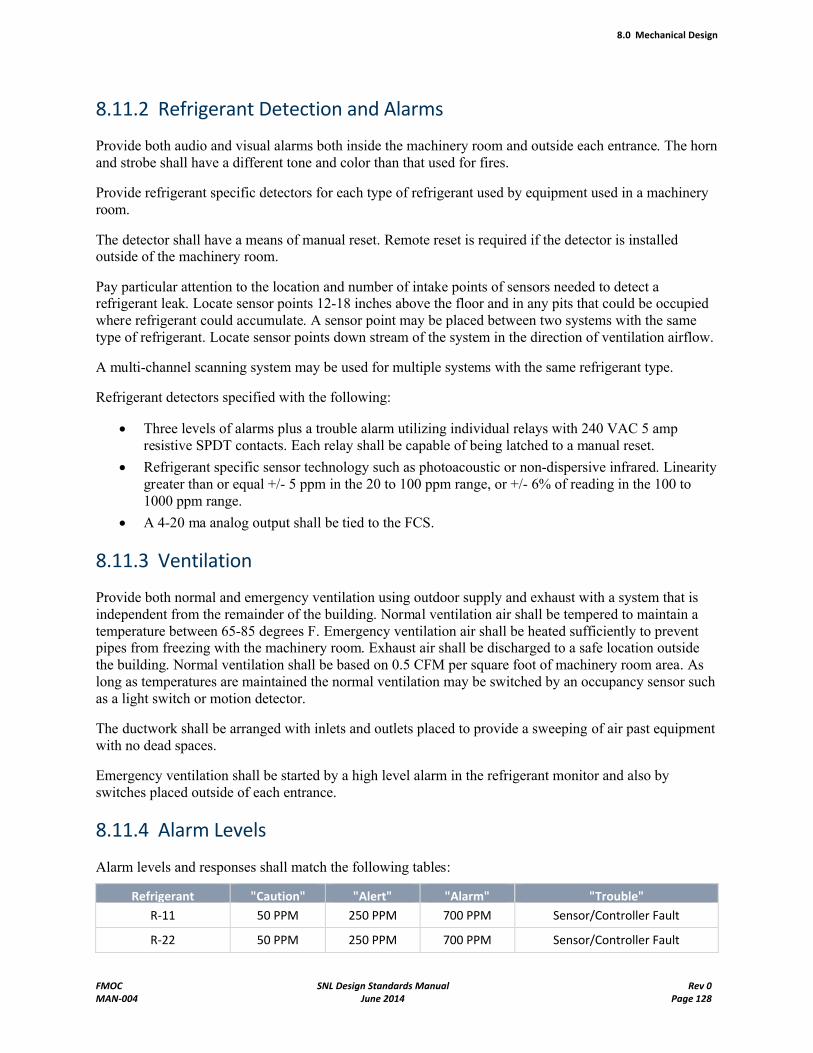
8.0 Mechanical Design
FMOC SNL Design Standards Manual Rev 0MAN-004 June 2014 Page 128
8.11.2 Refrigerant Detection and Alarms
Provide both audio and visual alarms both inside the machinery room and outside each entrance. The horn and strobe shall have a different tone and color than that used for fires.
Provide refrigerant specific detectors for each type of refrigerant used by equipment used in a machinery room.
The detector shall have a means of manual reset. Remote reset is required if the detector is installed outside of the machinery room.
Pay particular attention to the location and number of intake points of sensors needed to detect a refrigerant leak. Locate sensor points 12-18 inches above the floor and in any pits that could be occupied where refrigerant could accumulate. A sensor point may be placed between two systems with the same type of refrigerant. Locate sensor points down stream of the system in the direction of ventilation airflow.
A multi-channel scanning system may be used for multiple systems with the same refrigerant type.
Refrigerant detectors specified with the following:
Three levels of alarms plus a trouble alarm utilizing individual relays with 240 VAC 5 amp resistive SPDT contacts. Each relay shall be capable of being latched to a manual reset.
Refrigerant specific sensor technology such as photoacoustic or non-dispersive infrared. Linearity greater than or equal +/- 5 ppm in the 20 to 100 ppm range, or +/- 6% of reading in the 100 to 1000 ppm range.
A 4-20 ma analog output shall be tied to the FCS.
8.11.3 Ventilation
Provide both normal and emergency ventilation using outdoor supply and exhaust with a system that is independent from the remainder of the building. Normal ventilation air shall be tempered to maintain a temperature between 65-85 degrees F. Emergency ventilation air shall be heated sufficiently to prevent pipes from freezing with the machinery room. Exhaust air shall be discharged to a safe location outside the building. Normal ventilation shall be based on 0.5 CFM per square foot of machinery room area. As long as temperatures are maintained the normal ventilation may be switched by an occupancy sensor such as a light switch or motion detector.
The ductwork shall be arranged with inlets and outlets placed to provide a sweeping of air past equipment with no dead spaces.
Emergency ventilation shall be started by a high level alarm in the refrigerant monitor and also by switches placed outside of each entrance.
8.11.4 Alarm Levels
Alarm levels and responses shall match the following tables:
Refrigerant "Caution" "Alert" "Alarm" "Trouble"
R-11 50 PPM 250 PPM 700 PPM Sensor/Controller Fault
R-22 50 PPM 250 PPM 700 PPM Sensor/Controller Fault
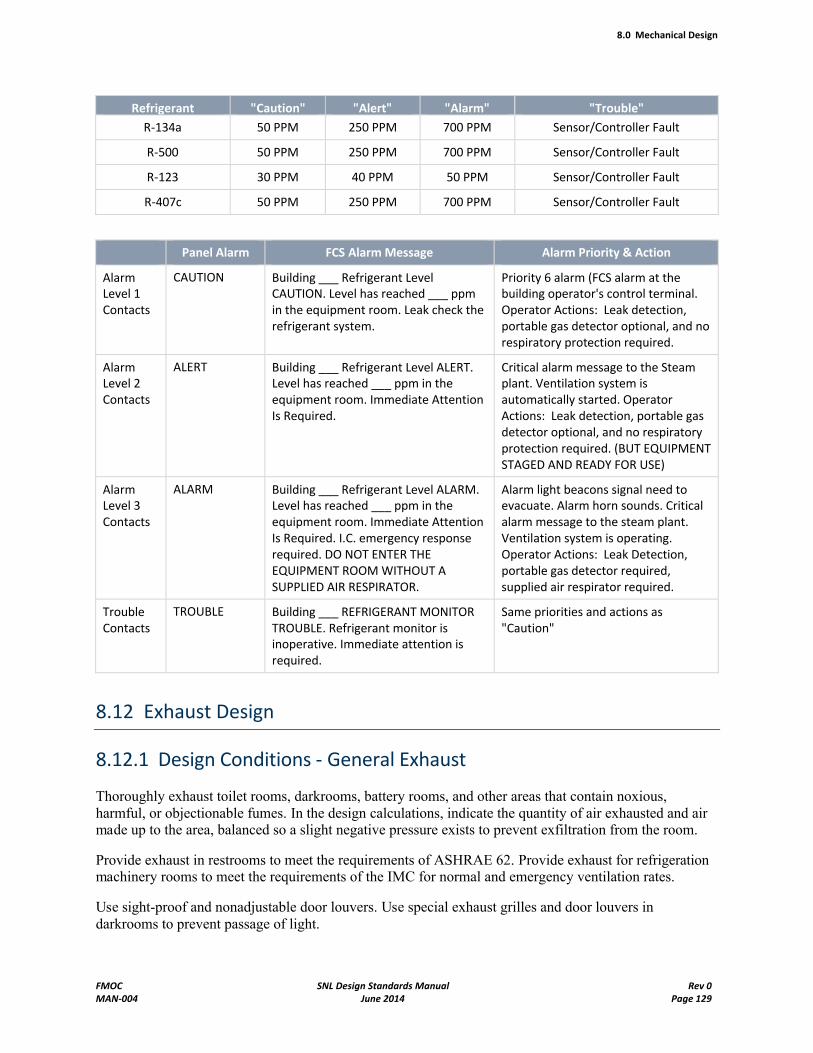
8.0 Mechanical Design
FMOC SNL Design Standards Manual Rev 0MAN-004 June 2014 Page 129
Refrigerant "Caution" "Alert" "Alarm" "Trouble"
R-134a 50 PPM 250 PPM 700 PPM Sensor/Controller Fault
R-500 50 PPM 250 PPM 700 PPM Sensor/Controller Fault
R-123 30 PPM 40 PPM 50 PPM Sensor/Controller Fault
R-407c 50 PPM 250 PPM 700 PPM Sensor/Controller Fault
Panel Alarm FCS Alarm Message Alarm Priority & Action
Alarm Level 1 Contacts
CAUTION Building ___ Refrigerant Level CAUTION. Level has reached ___ ppm in the equipment room. Leak check the refrigerant system.
Priority 6 alarm (FCS alarm at the building operator's control terminal. Operator Actions: Leak detection, portable gas detector optional, and no respiratory protection required.
Alarm Level 2 Contacts
ALERT Building ___ Refrigerant Level ALERT. Level has reached ___ ppm in the equipment room. Immediate Attention Is Required.
Critical alarm message to the Steam plant. Ventilation system is automatically started. Operator Actions: Leak detection, portable gas detector optional, and no respiratory protection required. (BUT EQUIPMENT STAGED AND READY FOR USE)
Alarm Level 3 Contacts
ALARM Building ___ Refrigerant Level ALARM. Level has reached ___ ppm in the equipment room. Immediate Attention Is Required. I.C. emergency response required. DO NOT ENTER THE EQUIPMENT ROOM WITHOUT A SUPPLIED AIR RESPIRATOR.
Alarm light beacons signal need to evacuate. Alarm horn sounds. Critical alarm message to the steam plant. Ventilation system is operating. Operator Actions: Leak Detection, portable gas detector required, supplied air respirator required.
Trouble Contacts
TROUBLE Building ___ REFRIGERANT MONITOR TROUBLE. Refrigerant monitor is inoperative. Immediate attention is required.
Same priorities and actions as "Caution"
8.12 Exhaust Design
8.12.1 Design Conditions - General Exhaust
Thoroughly exhaust toilet rooms, darkrooms, battery rooms, and other areas that contain noxious, harmful, or objectionable fumes. In the design calculations, indicate the quantity of air exhausted and air made up to the area, balanced so a slight negative pressure exists to prevent exfiltration from the room.
Provide exhaust in restrooms to meet the requirements of ASHRAE 62. Provide exhaust for refrigeration machinery rooms to meet the requirements of the IMC for normal and emergency ventilation rates.
Use sight-proof and nonadjustable door louvers. Use special exhaust grilles and door louvers in darkrooms to prevent passage of light.
8.0 Mechanical Design
FMOC SNL Design Standards Manual Rev 0MAN-004 June 2014 Page 130
8.12.2 Design Conditions - Local Exhaust Ventilation
Local exhaust ventilation (LEV) is preferred over dilution ventilation for controlling hazardous vapors, gases, and particles. The Local Exhaust Ventilation Program is managed by the Industrial Hygiene Department (10327). Industrial hygienists are assigned to Customer Support Teams (CSTs) who support Sandia/NM line organizations requesting work, and are knowledgeable about the operation and conditions of exposure. They are an essential source of information during the design of the LEV system. The CST shall be consulted in the planning stages of any new LEV/High-Efficiency Particulate Air (HEPA) filtration system or upon request to modify any existing LEV/HEPA system. Refer to the ES&H manual (Chapter 6, Section P) for additional information about LEV systems.
Clearly define the source of all exhaust air, and provide clean, tempered air into the space to replace exhaust air. The designer shall assist the line organization and Industrial Hygiene in the selection of exhaust hoods and controls for each application, and the exhaust system for which the hoods are to be used.
Design hoods, and calculate exhaust requirements based on similar applications found in "Specific Operations" of the latest edition of the American Conference of Governmental Industrial Hygienists' (ACGIH) Industrial Ventilation Manual or Sandia/NM's Mechanical Standard Drawings. All "non-standard" LEV designs require an Industrial Hygiene review. Non-standard is defined as a design that does not appear in common reference text such as the Industrial Ventilation Manual. LEV systems must be installed per manufacturer instructions, the requirements/guidelines identified in American Industrial Hygiene Association (AIHA)/American National Standards Institute (ANSI) Laboratory Ventilation Z9.5, the ACGIH Industrial Ventilation Manual, and good engineering practices for systems intended for worker health and safety, as defined by Sandia National Laboratories Facilities and Industrial Hygiene.
The location of the fume hood within a space can have an impact on the effectiveness of the exhaust equipment. The mechanical designer shall provide guidance to architectural designers on layout requirements for fume hoods. Locate fume hood faces 10 feet or more from the closest air supply or exhaust point, but not in or along normal traffic routes. A fume hood should not be located where room air currents greater than 50 linear feet per minute will disrupt uniform air entrance at the hood face.
Fume hood face velocity depends on the capture containment requirements of the hazard, room supply air distribution, traffic past the hood, and the amount and location of equipment in the hood. Fume hood full-open-area face velocity settings can be between 80 and 100 feet per minute, depending on the quality of supply air distribution, the level of hazard, and the quality of the fume hood. Generally, a face velocity of 100 feet per minute is satisfactory if the quality of supply air distribution is adequate, traffic past the hood is low, and there is no equipment in the hood closer than 6 inches to the hood's face. Regulated carcinogens and radiological hoods require higher face velocities.
All fume hoods require an airflow indicator: a simple vanometer, differential pressure gauge, or a morecomplex Variable Air Volume (VAV) control system. Coordinate with the Sandia/NM line organization to determine which device to use, and whether to order it with the hood or install it during construction.
Systems handling particles require that minimum transport velocities be maintained throughout the system. Although systems handling vapors and gases have no minimum duct velocity criteria, duct velocities of 2000-3000 feet per minute usually result in a good balance between initial and operating cost. Use round ducts for exhaust systems whenever possible. Round ducts resist collapse, provide better aerosol transport, seal easier, and use less metal than rectangular ducts.
8.0 Mechanical Design
FMOC SNL Design Standards Manual Rev 0MAN-004 June 2014 Page 131
Provide separate exhaust systems for process exhausting of incompatible hazardous fumes, gases, etc. Specify the type of duct material and coatings to use throughout the system, compatible with the material being exhausted. Consult with Industrial Hygiene when unsure of how chemicals will react.
Calculate exhaust requirements for closed-type glove boxes for 50 cubic feet per minute (minimum) per glove box.
Exhaust vacuum-pump-oil mist to the outside, or to the building exhaust system.
HEPA systems used in radiological applications shall be installed per manufacturer instructions, the requirements/guidelines identified in the DOE Nuclear Air Cleaning Handbook DOE-HDBK-1169, and the Code on Nuclear Air and Gas Treatment American Society of Mechanical Engineers ASME AG-1, and good engineering practices for systems intended for worker health and safety, as defined by Sandia National Laboratories Facilities and Industrial Hygiene.
Exhaust system flow schematics shall be prepared for all systems with multiple exhaust hoods. Existing flow schematics shall be modified to reflect all changes made to exhaust systems. Schematics shall indicate each source of exhaust, room number, type of hood, design flow rates, riser flow rates, fan flow rates, dampers, filters, and all other components of the exhaust system.
8.12.3 Exhaust Fans
Calculate the total pressure requirements for sizing exhaust fans. Account for system effect losses, and lay out the supply and exhaust connections to fans to reduce the system effect losses as much as practical.
Roof exhausters for general room exhaust shall be all aluminum, roof-mounted, curb-type, and centrifugal, with an integral weather cover, bird screen, back-draft damper, and roof disconnect. Mount the motor outside the air stream. Direct connection is preferred.
Specify the following operating conditions (altitude = 5500 feet) for roof-type exhaust fans:
Air quantity
Static pressure
Motor hp and rpm
Fan wheel size
Exhaust fans that serve acid, corrosive, or other fume hoods shall be utility-type, and epoxy-coated. Discharge fumes vertically upward at an exit velocity of 3000 feet/minute at a location and height sufficient to prevent re-entry of hazardous fumes. Extend exhaust stacks at least 10 feet above roof level or air intakes that are within 50 feet. Do not install a weather cap on stacks that discharge hazardous chemicals. Final determination of exhaust stack height shall be based on the ASHRAE Handbook of Fundamentals, "Airflow Around Buildings," to effectively dissipate effluent.
Coordinate design with structural and electrical designers to ensure proper stack support and lightning protection.
8.0 Mechanical Design
FMOC SNL Design Standards Manual Rev 0MAN-004 June 2014 Page 132
8.13 Ductwork Design
8.13.1 Design Conditions
Unless otherwise mentioned in the Design Criteria, design supply ductwork using the static-regain or equal friction method to ensure that design quantities of air will reach final outlets in the system. Examples of static-regain and equal friction system design are outlined in the ASHRAE Handbook of Fundamentals and the Carrier Corporation Design Manual.
Design return-air and exhaust systems in accordance with principles of equal pressure drop. This method ensures that proper air quantities will be returned from even the most remote opening. (Every path of air being removed from a particular area or room shall have the same pressure drop back to the fan inlet.) Coordinate ductwork layout with the structural designer to minimize penetrations through firewalls and fire-rated partitions. At these penetrations, fire and smoke dampers and access doors are required.
Specify that Duct Coordination Drawings be submitted on larger and more complicated system as per Standard Construction Spcecification15810 "Ductwork" Section 1.03, 'Submittals', when the design drawings cannot adequately show all the possible interferences.
Consider the requirement for a return air fan when return duct resistance exceeds 0.25 inches of water.
Duct run distances shall be as short as possible. Size the runs on the critical pressure path for minimum practical pressure.
Select diffusers for their ability to quickly mix supply air with room air introducing a maximum of supply air with a minimum throw. Ensure that airflow does not short circuit from the supply diffuser to the return-air openings. Avoid using combination air supply and return diffusers.
During design, select the throw from each diffuser so the throw is 90 percent of the distance from the diffuser to the nearest wall or other obstruction. In the case of diffusers with a downward vertical air pattern, select the throw to terminate above breathing level.
Provide means for balancing the air systems. Devices shall include but are not limited to dampers, flow measuring stations, temperature and pressure test connections, gauges, and flow sensors. Provide permanently installed devices on major equipment. Air monitoring devices shall be multi-point devices that can continuously measure total and static pressure.
Coordinate ductwork layout with Physical Security to minimize the number and size of ductwork penetrations through vaults, vault-type rooms and designated security areas. The penetrations larger than 96 square inches in diameter and larger than 6 inches in the smallest dimension (greater than 11 inches in diameter) require barriers or alarms. (See Chapter 11 for security barrier requirements).
8.13.2 Calculations Required
Present calculations for the design of all air-handling duct systems:
Duct sizing
Fan sizing
Size dampers that admit outside air by pressure drop, rather than face velocity. Calculate the largest drop from a return air register, then make the damper drop an equal value
8.0 Mechanical Design
FMOC SNL Design Standards Manual Rev 0MAN-004 June 2014 Page 133
Noise criteria (noise criteria curves).
8.13.3 Ductwork-General
Refer to Facilities Construction Standard Specification Section 15810, Ductwork, for sheet metal gauges, materials, equipment, and methods to be used, and the construction of ductwork.
Draw ductwork to scale (single-line diagrams are not acceptable). Thoroughly dimension the drawings. Clearly show register size, equipment list number, cubic feet per minute, pressure drop, and throw. Show all turning vanes in elbows, transitions, duct liners, and air proportioning vanes. Show the detail of all security barriers installed at vault, vault-type room and security area boundaries.
Diffuser size, cubic feet per minute, and throw should appear on plan drawings for each type and size of diffuser. Refer to diffusers with volume controls affixed to the upstream side as registers. A diffuser or return-air device with no volume control may be referred to as a grille. Identify noise criteria ratings in equipment lists.
Install access covers on both sides of heat-exchange devices in ducts. Ensure adequacy for complete cleaning and servicing.
A plenum ceiling return may be used where feasible.
Install fire dampers in all ductwork passing through firewalls, between floors, and where dictated by code requirements. Provide all fire dampers with standard commercial and catalog-listed access doors. For duct areas smaller than 1 sq. ft. provide a removable section of duct to fully access the fire damper.
Install security barriers in all ductwork greater than 96 square inches passing through security area boundaries. Inspection ports shall be installed for future audit verification of security barrier installations. Contact Physical Security (4243) for ductwork in which design or conditions do not allow for inspection ports. See Chapter 11 for security barrier requirements.
List the required duct pressure classification required for each duct segment on the schematic drawings. Unless otherwise stated on the drawings, Specification 15810 Ductwork, will require the following pressure classifications:
From the fan to the VAV box – 4" w.g. positive
Downstream of the VAV box – 1" w.g. positive
Return air – 1" w.g. positive or negative
Lab exhaust – 4" w.g. negative
Restroom and general exhaust – 2" w.g. negative
For pressures less than negative 4" w.g. or greater than positive 10" w.g., and for highly corrosive exhaust, ductwork shall be constructed to SMACNA Round Industrial Duct Construction Standards of SMACNA Rectangular Duct Construction Standards. In these situations the designer is required to specify other operating criteria for the contractor to use in applying the standard such as materials, joint type, exterior loads, maintenance loads, corrosive environment.
Provide duct support details for ducts located on the exterior of the building and for all equipment.
Fire and smoke dampers shall be specified for "Dynamic Closure" in a fire event to shut off against airflow at a minimum of 2375 FPM and 4 in.wg. for horizontal or vertical flow.
8.0 Mechanical Design
FMOC SNL Design Standards Manual Rev 0MAN-004 June 2014 Page 134
For large and more complicated jobs, the designer, in accordance with Specification 15810 Ductwork, may request shop drawings, duct reinforcement information, and hanger details. This additional information must be requested through the submittal list.
8.14 Compressed-Air System Design
8.14.1 Design Conditions
Normal Shop and Controls – Pressure: 125 psig.
Laboratory and Special Use – Determine the pressure based on equipment requirements.
8.14.2 Calculations Required
Capacity and pressure drops
Storage capacity
Percent of running time for the compressor selected.
8.14.3 Piping Materials
Refer to Facilities Construction Standard Specification Section 15051, Piping Systems.
8.14.4 Equipment
For normal shop and control air applications, the compressor shall be a two-stage, air-cooled, pressure-lubricated, motor-driven, tank-mounted unit. For units above 15 hp, a water-cooled model is indicated and a separate vertical air receiver is preferred. The compressor shall be capable of delivering rated cubic feet per minute of free air at the design altitude. Laboratory applications may require clean, dry compressed air from oil free rotary screw or rotary lobe compressors or oil lubricated rotary compressors with high efficiency oil removal filters and dryers.
The receiver shall be ASME National Board registered, rated, and certified, and stamped for 200-psig working pressure. In extended distribution systems, show auxiliary receivers at remote points. Receiver tanks between 18 and 36 inches in diameter shall have two 4- by 6-inch handholes at each end of the shell. Tanks over 36 inches in diameter shall have a 12- by 16-inch manhole. Install air receivers so all drains, handholes, and manholes are easily accessible. Show details of tank support.
Install ASME-approved relief valves, preferably on the receiver or at the output of the compressor. Set for the rated working pressure of the most vulnerable portion of the system, that is, the receivers. These relief valves shall be 3/4-inch National Pipe Thread or larger and have an outside lifting lever. Relieving capacity shall be larger than the compressor displacement.
Systems 5 hp and greater shall be provided with an elapsed-run time meter.
When two or more compressors are installed, install a means to efficiently operate the compressed air system.
Gauges on receivers shall have a range equal to 1-1/2 times the safety valve setting.
8.0 Mechanical Design
FMOC SNL Design Standards Manual Rev 0MAN-004 June 2014 Page 135
8.14.5 Compressed-Air System-General
Size the distribution system to provide extra storage capacity at times of maximum demand and to provide for possible future expansion of the system. Show valved drip legs at low points in the system.
Install a refrigerant air dryer for air compressors 5 hp and greater. If available year-round, run chilled water through an after-cooler. If chilled water is not available, use a self-contained refrigerant dryer. Use a float trap to remove any condensed material above a drip leg before the material enters the receiver. Drain the low point in the receiver with a timer operated solenoid valve
The first 4 feet of service line from the tank of a tank-mounted air compressor shall be reinforced braided flex connections. Install larger, water-cooled models having separate tanks with lengths of flexible metal hose in two planes, one of which is installed between the compressor and the aftercooler and parallel to the compressor crankshaft.
Wherever possible, large air compressors should take their air from outside the building through a suitable oil filter.
8.15 Pressure Systems
8.15.1 General
Sandia defines a pressure system as an assembly of pressure-containing components typically consisting of pressure vessels, piping, valves, pumps, instruments, etc., which are capable of maintaining fluid (liquid or solid) at a pressure different than atmospheric. This definition is intentionally broad to include the variety of systems with both positive pressures and vacuums that can present hazards to individuals and facilities.
The Sandia facilities organization is responsible for designing a wide variety of pressure systems that ultimately are owned, operated, and maintained by either the facilities organization or a line organization.
In an effort to provide a safe environment for pressure related applications Sandia has instituted a Pressure Safety Program that contains policies for all designers, installers, and operators of pressure systems. The mechanical designer of a pressure system is responsible for meeting the requirements of the Pressure Safety Program as contained in the Pressure Safety Manual. The program and manual are located at psi.sandia.gov:
8.15.2 Minimizing Risk and Exposure
The design shall consider the following techniques to achieve minimal risk and exposure to the hazards of pressure systems:
1. Identify all hazards and consequences.
2. Minimize pressure and volume.
3. Use recognized standards.
4. Design conservatively
5. Use materials with predictably safe failure modes. Brittle materials sometimes fail unpredictably.
6. Demonstrate structural integrity by overpressure test.
7. Operate within the original design intent.
8.0 Mechanical Design
FMOC SNL Design Standards Manual Rev 0MAN-004 June 2014 Page 136
8. Provide backup protection.
9. Use proven hardware.
10. Use protective shields.
11. Use tiedowns.
12. Go "remote."
8.15.3 Pressure Limitations
The mechanical designer shall review the pressure limitations of all components and their relationship to the following levels of pressure:
System Operating Pressure
Set Pressure and Opening Range of Relief Devices
Maximum Allowable Working Pressure (MAWP)
Overpressure Test Pressure
Predicted Failure Pressure
Sandia Facilities Standard Construction Specifications have been developed to meet the requirements of the Pressure Safety Program for their intended systems. The designed shall consider the limitations of each standard specification before selecting it to use for a new system or modifications to an existing system. When any new system will operate outside the range of the standard specifications the designer shall either modify the standard specifications or create a new specification that incorporates all of the requirements and intent of the Pressure Safety Program.
8.15.4 Data Package
A data package is required for all pressure systems. It contains information on the system description/hazards and contains ratings, materials of construction, and documents the configuration of the system. For most facilities owned systems the requirements of the data package are contained in the facilities drawings, specifications, and component submittals and no additional effort is required to prepare the package. For systems owned by a line organization the designer shall assist the owner in preparing the data package by forwarding drawings, specifications, and submittals to the owner upon completion of the project.
8.16 Special Gases
See the Design Criteria for design conditions and required calculation.
All compressed-gas cylinder valve outlet and inlet connections shall conform to the standard of the Compressed Gas Association Standard V-1.
Provide gas cylinder wall racks for gas cylinders at all manifold and storage locations.
8.0 Mechanical Design
FMOC SNL Design Standards Manual Rev 0MAN-004 June 2014 Page 137
8.17 Pressure Vessels
8.17.1 Design Conditions
All vessels shall conform to the ASME Code, including Section VIII, Division I. All vessels shall be ASME National Board certified, registered, and stamped, and meet the impact requirements of UG-84 with no exceptions. Include the requirement for ASME Form U-1A, Manufacturer's Data Report for Pressure Vessels, in the list of required descriptive submittals. Pressure vessels shall be fully described in the equipment list. Include the statement, "No ASTM A-515, ASME SA-515-type steel will be used in the fabrication of this vessel," in the description and specifications.
8.17.2 Calculations Required
Present calculations on the sizing of all portions of the pressure vessels, including connections and fasteners.
8.17.3 Pressure Vessel–General
The pressure vessel detail drawing shall show all construction and installation dimensions and sizes. Provide a 2-inch plugged opening in the center of the head at each end of vessels under 18 inches in diameter. Use openings for inspection purposes only. Locate inspection openings for clear access. Maintain at least a 24-inch clearance in front of all access holes. Pressure vessels between 18 and 36 inches in diameter will have two 4- by 6-inch handholes at each end of the shell. Tanks over 36 inches in diameter will have a 12- by 16-inch manhole. Show the tank support structure on the pressure vessel detail.
Provide suitable taps for a thermometer well, a pressure gauge, and a relief valve in addition to taps required for service connections. Provide a 3/4-inch minimum tap at the low point to facilitate complete gravity drainage of the vessel. Details of the tank shall show locations and sizes of all openings.
8.17.4 Above-Ground Storage Tanks for Flammable and Combustible Liquids
Above-ground storage tanks for flammable and combustible liquids shall be installed in accordance with the International Building Code (IBC), the International Fire Code (IFC) and NFPA 30. All plans concerning the installation or use of above ground storage tanks shall be submitted to Sandia/NM Fire Protection Engineering for review prior to installation.
8.18 Relief Valves
8.18.1 Design Conditions
Without exception, size the relief valve(s) to relieve the unregulated capacity of the PRV, burner, pump, and compressor or prime mover, with no more pressure accumulation than the appropriate code recommends. Factory set the PRVs at the pressure rating of the piece of equipment having the lowest working pressure for that section of the system. All relief valves shall be 3/4-inch minimum pipe size and
8.0 Mechanical Design
FMOC SNL Design Standards Manual Rev 0MAN-004 June 2014 Page 138
have an external lifting lever. Set the temperature and pressure relief valve on domestic hot water systems for 125 psig and 210°F.
Because the unregulated capacity of devices manufactured by different companies may vary, do not callout the size of the relief valves on the drawings unless it is known beyond doubt (that is, existing installed equipment or Sandia/NM-furnished equipment).
From the manufacturer's regularly published ratings, report the unregulated capacity for a given device as unregulated capacity. The highest ratings shown in standard capacity tables are usually not unregulated and shall not be treated as such. Where the issue is in doubt, a letter from the manufacturer (not the local agent) is required.
In the case of steam-fired equipment, assume that a tube could break and the control valve could simultaneously deliver unregulated flow. Provide the water side with a relief valve sized to relieve the unregulated capacity of the steam control valve. A relief valve sized only for the capacity of the heat-transfer surface is not acceptable.
8.18.2 Calculations Required
Present relief valve calculations to show the maximum amount of medium in question to be released.
8.18.3 Relief Valves—General
Provide each steam, compressed air, compressed-gas, hot water, or hydraulic system with ASME National Board certified, registered, and stamped relief valves. Pipe the discharge from a steam relief valve to the outside in a manner that will protect passers-by when it discharges. Pipe liquid effluent from other relief valves to the nearest floor drain or floor sink through an air gap two pipe diameters of the supply inlet, but in no case less than 1 inch. Ensure that relief valves are not obstructed or prevented from discharging by other equipment.
8.19 Standby Equipment
Only when indicated in the Design Criteria (which defines design requirements for the specific project), install tower, chilled, and heating water pumps in pairs with suitable valving so one pump can be turned on within minutes while the other pump is taken off-line for repairs.
8.20 Bird Screens
Provide all exterior building mechanical and equipment penetrations with a 1/2-inch-mesh, galvanized bird screen. Provide insect screens to areas that handle food, service equipment, or do not have filters to stop insects. Locate screens so they can be easily changed or cleaned.
8.21 Equipment on Roof
It is preferable to locate air intakes and exhausts on roofs and orient them to minimize adverse wind effects. All outside intakes should be at least 15 feet from flues, sewer vents, and exhausts. Where air intakes or exhausts are located on walls or less than 2 feet above the roof peak, prepare detailed wind-
8.0 Mechanical Design
FMOC SNL Design Standards Manual Rev 0MAN-004 June 2014 Page 139
pressure calculations and show the discharge of air at the various wind velocities. Thoroughly detail stacks and vents to show flashing and counter flashing.
If a curb other than those shown on standard detail drawings is used, then curb details shall appear on the architectural sheets. Set up items not suitable for curb mounting at a minimum of 18 inches above the roof surface on an angle-iron stand with steel-pipe legs (per architectural standard drawings) so reroofing can be done under them. Extend the stand's legs to the structural members and flash with flexible pipe boots or single-ply flashings where appropriate.
Provide walkway pads on the roof leading from the access door to mechanical equipment that requires regular service. Whenever mechanical equipment is roof-mounted, call out permanent access ladders leading to the roof, except where security measures dictate otherwise. Locate water-using equipment so
Over-spray will not be a problem
Equipment can be readily drained, will not freeze up, and can be easily worked on
No short-circuiting of air will occur.
Provide at least a 6-foot clearance between roof-mounted equipment and the edge of the roof, or provide suitable pipe-rail guards.
The mechanical designer is responsible for transmitting accurate information concerning size, weight, and dynamic loadings associated with roof-mounted mechanical equipment to the structural designer.
8.22 Instrumentation
Drawings shall indicate self-sealing test plugs, pressure gauges, thermometers, flowmeters, draft gauges, thermometer wells, and other instrumentation so equipment performance can be evaluated withoutshutting the equipment down or resorting to portable instrumentation when installing necessary instruments. Instruments shall measure temperatures and pressure drops in and out of heat-exchange devices using in-line installed self-sealing test plugs. In addition, install a diaphragm-actuated, dial-type gauge to measure (in inches of water) the drop across all filter banks and fans, with the possible exception of fans in small packaged units. Supply outdoor units with weather shields. Use bimetal dial type thermometers for mounting in thermowells in the piping. Mount remote-bulb thermometers on a centrally located panel together with remote-bulb or sensing controllers. Show instrumentation on the flow schematics and details.
Remote monitoring and alarm instrumentation is done by an FCS. See Chapter 8.23.1, Facilities Control Systems.
8.23 Controls
8.23.1 Facilities Control Systems (FCS)
Sandia/NM uses a Landis & Siemens System 600 FCS with direct digital control, to monitor and control HVAC systems in the buildings. This FCS shall be included in the design of all facilities greater than 10,000 square feet, unless otherwise specified by Sandia/NM. Because of the unique design of this control system, all of the information pertaining to this system is provided below.
8.0 Mechanical Design
FMOC SNL Design Standards Manual Rev 0MAN-004 June 2014 Page 140
Specifications and Design Guidelines
The mechanical engineer issues the control discipline specifications. The following documents should be obtained before starting the control design:
Project – Specific Design Criteria
Facilities Construction Standard Specification Section 13943, Facilities Control Systems
Sandia/NM Standard Drawings: MI5001STD, MI6001STD, MI6002STD
Monitoring
HVAC systems are monitored by a system of digital and analog sensors located throughout equipment rooms and at selected locations in the building. The sensors are connected through a system of conduits and wires to field interface devices (FIDs). Critical alarm conditions are also reported at the existing reader/printer in the Central Steam Plant, which is continuously monitored. These alarm points are selected by Facilities Systems Engineering with input from Facilities Operations and Maintenance.
Control
Control of HVAC systems is by start-stop functions and direct digital control (DDC) generated by the FIDs and host computer, unless the HVAC application (for example, fan coil unit) warrants conventional electronic controllers. Analog output control signals will be programmed into the FIDs and connected to the various damper operators, valve operators, motor starters, etc., by a system of conduit and wires. Drawings shall contain complete sequences of control for each system (cooling, heating, exhaust, domestic hot water, smoke removal, solar, etc.). The relay contacts in the FIDs are rated at 5 amps at 250 VAC. Smoke detectors and freeze-stats should be hard wired to fan motors.
Smoke Removal and Fire Functions
The FCS does not respond to smoke, fire, or sprinkler water flow alarms unless the sequence of operations designates that a unit, such as a supply fan, which is already controlled by the FCS, change its mode of operation. When this is a requirement, provide a contact closure from the Fire Alarm Control Panel (FACP) or Signal Line Circuit (SLC) control module that alerts the FID to the situation. If additional requirements must be met, such as starting smoke removal fans (functions that are not controlled by the FID), then these requirements will have to be accomplished by other control means, such as a relay that operates off an FACP or SLC control module contact.
When packaged air handler units are provided with smoke detectors, the detectors shall meet the requirements of Standard Specification 13852 (Intelligent Fire Alarm Systems)
System Definition and Presentation
The following drawings are required to define and illustrate the monitoring and control systems described above. Sample drawings of each type are available upon request from FCS Office, Mechanical Systems Engineering Department, and may be used to illustrate the desired format, symbols, etc. The samples shall not be considered as standards and reused as such. The only formats that should be regarded as standard are the FID layout drawing and the point numbering scheme, both of which are available from the FCS Office. The mechanical engineer shall develop a full set to be used in construction.
8.0 Mechanical Design
FMOC SNL Design Standards Manual Rev 0MAN-004 June 2014 Page 141
Flow Diagram and Sequence of Operation Sheets
Develop these drawings in two phases. The first submission shall provide the flow diagram of the intended system configuration, the proposed sequence of operation, and the DDC point selection. This set defines the base system for approval. After this basic approach has been accepted, then the monitoring and alarm points will be selected by Facilities Engineering. After the complete point selection is accepted, the remaining FCS drawings will be developed.
Field Interface Devices Layout Sheets
These drawings illustrate the layout and termination of input and output field connections in the FID cabinets. Twenty-five percent capacity of each point type shall be reserved in the panels.
Point List and Definition Sheets: Input/Output (I/O) Summary
These drawings provide a compilation of the total points selected and show point nameplate data, reference drawings, device symbol and number, and device range (established by the designer).
Component Location Plan
These floor plans shall locate all components in a system (for example, FIDs, sensors, actuators for dampers, valves, motor starters, etc.) and the conduit that interconnect the items. A scale of 1/8 inch per foot or smaller is suggested to allow better coordination of the various items in the system. Keep all FID cabinets a minimum of 5 feet (1.5 meters) away from power sources greater than 100 kVA and any Variable Frequency Controllers.
Conduit Schedules
These sheets present the coordination of the wires contained in conduits between sensors and FIDs.
Control Ladder Diagrams
Provide ladder diagrams for each piece of equipment energized/de-energized by the FCS.
Equipment List
These drawings list only the equipment or components peculiar to the control discipline. Identify the items in a similar manner as other items but with a number enclosed in a diamond. Include the full specifications for ordering. Specify sensors that are totally compatible with the Landis and Siemens System and that are field-calibratable. There are, however, many vendor sources to provide competition for bidding. A sample listing of sensors of high reliability and performance, that still ensures competitive selection, can be obtained from the Facilities FCS Department.
The intent of the design procedures just presented is to develop a complete set of contract documents so the contractor will furnish and install sensors, conduit and wire, pneumatic damper and valve operators, and tubing field locations to the FID panels. The contractor installs the FID cabinets and internal components and connects the wiring and pneumatic tubing. Reference Facilities Construction Standard Specification Section 13943, Facilities Control Systems, for the complete set of requirements.
8.0 Mechanical Design
FMOC SNL Design Standards Manual Rev 0MAN-004 June 2014 Page 142
Sandia/NM furnishes the following:
FID cabinets and all internal components, and instructions on how to terminate the wires and tubing. Plant Control Center personnel install the majority of the internal components
All required programming and loading at points listed in the I/O summary into the host computer to implement the sequence of operation delineated on the drawings
Downloading of programs into the FID and assisting the contractor with commissioning of the complete monitoring and controls system for the building.
8.23.2 Pneumatic, Electric, Electronic Controls
The use of pneumatic controls shall be avoided on future projects whenever other types of controls are available to perform satisfactorily and safely.
Thoroughly detail temperature, humidity, pressure change, action, and type of each controller. Where pneumatic systems are used, consider the entire effective range on industrial controllers.
Completely describe the step-by-step sequence of operation for each device in the control system (whether electric, electronic, or pneumatic) on the drawings, rather than in the specifications. Show the pneumatic pressures for both ends of the throttling range that correspond to temperatures on the drawings. In every instance, specify a pressure gauge at each unit of a pneumatic system. No air gauges are required where thermostats are flush-mounted with concealed connecting tubing.
Where FCS does not provide the control function, set up the control system around electronic or direct digital controllers that can be provided by a single supplier, and identify each item of equipment with the current product number. On the mechanical equipment list, show those items with an electrical connection. Provide a device description, range, set point, differential, contact rating, product number, etc., on the equipment list.
Equip pneumatic control systems with an automatic refrigeration air dryer, a compressed air prefilter, and an oil coalescing filter installed in the system's supply line to ensure dry and clean control air. Provide an automatic low-limit bypass to bypass air around the dryer in the event of a freeze-up.
Do not install pneumatic controls outside or in other unheated locations. Use electric actuators wherever control equipment may be exposed to sub-freezing weather.
Designs for building additions should be compatible with the original building system.
Where FCS sensing and control is not utilized, use a combination heating/cooling thermostat in preference to separate heating and cooling thermostats in a given area. Use 7-day programmable auto-changeover thermostats wherever possible.
In addition to detailed wiring diagrams that may appear on the electrical drawings, include a functional diagram on the mechanical drawings for all systems to show the entire sequence and general scheme of operation and all set points. Superimpose the functional diagram on a flow diagram of the heat transfer process.
See Chapter 8.23.1 for Facilities Control Systems requirements. Where FCS does not provide the control function, see Chapter 9.7, Control System Design, for the control drawings required on electrical control systems.
8.0 Mechanical Design
FMOC SNL Design Standards Manual Rev 0MAN-004 June 2014 Page 143
Size control valves with consideration to operate at system pressures and with flow and pressure drop clearly indicated.
Refer to Facilities Construction Standard Specification Section 13943, Facilities Control Systems, for additional information.
8.23.3 Controls for Non-FCS Buildings
Install the following special controls for energy conservation in small-sized buildings (less than 10,000 square feet) that do not merit FCS involvement. If a nearby building has an FCS installed, connect the small size building to the nearby FCS and use the FCS in lieu of the programmable time switch mentioned below.
Equip smaller buildings with a programmable thermostat that provides night temperature setback and disables cooling during unoccupied hours.
Buildings with central systems shall have the following special automatic controls:
A 7-day programmable time switch with a bypass switch to shut down the following:
Noncritical exhaust system
Heating water circulating pump and steam coil
Supply fans
Return-relief and noncritical exhaust fans
Building air conditioning equipment, such as chilled water circulating pumps or air conditioning condensers and compressors
Domestic hot water circulating pumps
Outside air dampers (close).
Provide the following to protect the building during extreme outside low temperatures:
Thermostat located in a sensitive place in the building that will restart the following when the interior temperatures drop below 55°F
Supply fans, if the building does not have perimeter heating
Heating water circulating pump and steam coils.
Time-delay relay for fast warm-up to turn on the following if the building low-temperature thermostat has not reacted. (Provide a bypass switch around the timer.)
Supply fans
Heating water circulating pumps, steam coil during winter season, or air conditioner and chilled water pump during summer
Bypass the hot water reset control from the normal heating schedule.
Additional features to reinstate the building to normal operating status at the beginning of the work period per the following:
Startup of domestic heating water circulating pump
Startup of noncritical exhaust fans
8.0 Mechanical Design
FMOC SNL Design Standards Manual Rev 0MAN-004 June 2014 Page 144
Opening of dampers to the normal, mixed, and outside control position
Restart of the return-relief fans.
8.24 Vibration Isolation and Alarm
8.24.1 Design Conditions
Select rotating equipment to vibration levels measured in any plane on the bearing cap (in the installed and operating condition) in accordance with Construction Standard Specification 15200, Vibration Limits and Control.
Show large supply fans, compressors, utility exhausters, and other rotating and reciprocating equipment mounted on vibration isolating bases incorporating springs, so 90 percent of the lowest disturbing frequency is isolated from the structure. Indicate in the equipment list the type of isolation that is to be supplied. Add special instructions for the equipment manufacturer to provide a coordinated isolation system.
Isolate mechanical equipment that has extremely high noise or vibration levels, including the distribution piping, on springs to minimize the transmission of vibration or noise into the building components and occupied spaces.
Connect an alarm signal to the FCS at the same location where special vibration switches are installed to shut down equipment.
8.24.2 Calculations Required
Provide written evidence of how isolation was selected for equipment installations that produce vibration or noise in usual ranges. Installation of equipment that produces extremely high levels of noise or vibration requires the following calculations:
Static deflection
Fundamental natural frequencies of machine mounting system.
8.24.3 General
Provide raised concrete pads isolated from the building structure with elastomer-bonded glass fiber material under all major items of equipment, pumps, etc. It is the responsibility of the mechanical designer to transmit this information to the structural designer so it can be shown on the structural drawings.
Make the final attachment of ductwork to fans with inorganic flexible connections. Use weatherproof connections when exposed to the weather. Flame-retardant flexible connections are generally recommended. Use noncombustible connections on piping that contains flammables. Use flexibleconnections to connect building piping to air compressors (see Chapter 8.15, Compressed-Air System Design).
Connect refrigeration piping to compressors with refrigerant pressure-rated flexible metallic sections, oriented parallel to the crank shaft.
8.0 Mechanical Design
FMOC SNL Design Standards Manual Rev 0MAN-004 June 2014 Page 145
Make final connections of fluid piping to pumps, towers, and other vibrating machinery with suitable flexible connections, such as "Resistoflex" bellows. Provide adequate anchoring of piping next to flexible connections.
Use spring-loaded pipe hangers when necessary to prevent vibration and sound transmission.
Add notes to the description in the equipment list to instruct the vendor of noise or vibration-producing equipment in excess of 5 hp. The vendor shall certify that the equipment and its supporting structures have been balanced statically and dynamically and that they are free from natural frequencies within 30 percent of its operating speeds.
Detail mounting frames where required (for example, roofs). Do not indicate overall dimensions. Relate the size to the equipment being supplied to obtain a coordinated system.
8.25 Sound Control
8.25.1 Design Conditions
Unless otherwise noted in the Design Criteria, establish design goals according to good engineering practice and the ASHRAE Guide and Data Book tables of design goals for sound control.
8.25.2 General
Minimize noise transmission throughout the structure. Establish that noise generated from outdoor equipment will not disturb neighbors or indoor occupants.
Select fans, or other equipment that radiate directly into an occupied area, that are quiet enough to meet ASHRAE noise criteria curves for the occupancy. Select diffusers and grilles with sufficiently low velocity to provide a noise level that meets the ASHRAE noise criteria curve for the occupancy.
Design or select sound attenuating devices as required to meet the ASHRAE noise criteria curve for the occupancy.
8.26 Insulation
8.26.1 Calculations Required
Specify insulation for ducts, piping, and heat-producing equipment where economic operating cost savings will offset the cost of the insulation within its life expectancy. Assume that the life expectancy of insulation is not more than 20 years for laboratory and administrative applications. Insulation is usually required when the following conditions occur:
When the heat loss or gain of the ductwork or piping, without insulation, increases the energy requirements of the building.
When condensation can occur on the surface of the ductwork or piping. This is possible when the ambient dew point temperature is lower than the air or fluid temperature in the duct or pipe.
8.0 Mechanical Design
FMOC SNL Design Standards Manual Rev 0MAN-004 June 2014 Page 146
Calculate the insulation thickness necessary to prevent condensation on piping where domestic cold water or chilled water lines with 65°F or cooler water runs through spaces where the pipe temperature could be below the dew-point. Comply with ASHRAE Standard 90.1.
8.26.2 Insulation Materials
Refer to Facilities Construction Standard Specification Sections 15081, Duct Insulation, and 15083, Pipe and Equipment Insulation.
8.26.3 Insulation – General
In no case specify or accept a combustible-type insulator or duct liner.
8.27 Water Treatment
8.27.1 Open Recirculating Systems
All cooling towers and fluid coolers shall have a water treatment system installed. Install Schedule 80 PVC piping such that a sample line is taken from the tower water supply line, to a conductivity controller, and returned to the tower water return line. Provide chemical injection points downstream of the controller. Check valves shall be installed on either side of these chemical injection points on a vertical section of pipe so as to protect the controller and chemical feed tanks from reverse flow conditions. Minimize the use of pure chemical feed lines, when feasible to do so. The controllers, sensors and injection pumps shall be Sandia/NM furnished and contractor installed. Each system shall have:
Sized make-up and bleed lines and valves
Flow meters installed on both the makeup and bleed lines. These shall be pulsing-type flow meters, with an acceptable operating range. Where possible, the flow meters will be tied into the FCS.
Conductivity controller(s) and associated flow switch(es) installed, but not calibrated.
Provisions for the injection of biocide and scale/corrosion inhibitor chemicals downstream of controller by providing tie-ins for future installation of chemical feed lines (typically 3/8" or ½" lines).
Sufficient footprint and wall space for tanks, flow meters, controller(s), and sample line.
Sample line at controller.
Contact Sandia/NM systems engineer responsible for water treatment for further details of open, recirculating water treatment systems.
8.27.2 Chilled and Hot Water Closed Loops
Make provisions for the periodic injection of corrosion-inhibiting and biocide chemicals on closed loop systems. Install chemical pot feeder with sufficient clearance to pour in 5-gallon drum of chemical. Standard chemical pot feeder shall be stainless steel with a 0.5-micron polypropylene bag filter, operating pressure up to 150 psig, operating temperature up to 200oF, 40-gpm maximum flow and 3-psi pressure drop. Feeder shall be piped to the nearest floor drain. Consult Sandia/NM Standard Drawing
8.0 Mechanical Design
FMOC SNL Design Standards Manual Rev 0MAN-004 June 2014 Page 147
MP5013STD, "By-Pass Feeder," and the Sandia/NM Systems Engineer responsible for water treatment for further details of closed loop water treatment systems.
8.28 Painting and Pipe Identification
8.28.1 General
Where practical, specify a factory finish for all mechanical equipment. Paint all other mechanical items except in the equipment rooms. See Facilities Construction Standard Specification Section 09900, Painting.
After painting is complete, thoroughly identify all piping with appropriate Brady self-adhesive labels. Ensure that the mechanical contractor understands that he or she is responsible for the accuracy of labeling and the direction of flow.
8.28.2 Underground Utilities
Mark the location of all underground utilities with a continuous identifying tape buried in the pipe trench above the pipe. Refer to Facilities Construction Standard Specification Section 02200, Earthwork. In addition, mount utility marker posts with painted descriptive titles over underground utility lines in remote areas.
For utilities installed in remote locations, specify underground utility markers per Standard Drawing WU5006STD, Utility Markers for Buried Pipe and Cable.
8.29 Test and Balance
The mechanical designer is responsible for determining the extent of Test and Balance that is necessary to prove that systems and equipment are operating as intended. Normally the Test and Balance service is provided by a Test and Balance agency hired by Sandia/NM and working jointly with the construction contractor as specified in Construction Standard Specification 15901 – System Component Checkout and Balance. The designer is responsible for reviewing the final report to determine if the design intent will be achieved and for providing options on how to correct deficiencies.
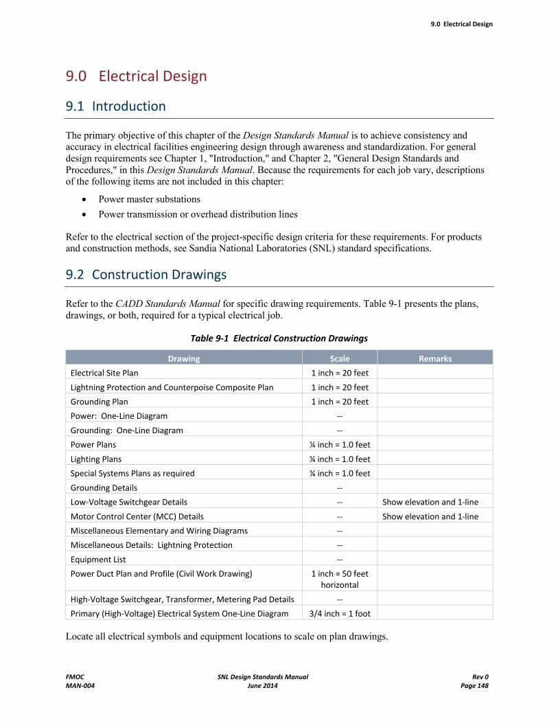
9.0 Electrical Design
FMOC SNL Design Standards Manual Rev 0MAN-004 June 2014 Page 148
9.0 Electrical Design
9.1 Introduction
The primary objective of this chapter of the Design Standards Manual is to achieve consistency and accuracy in electrical facilities engineering design through awareness and standardization. For general design requirements see Chapter 1, "Introduction," and Chapter 2, "General Design Standards and Procedures," in this Design Standards Manual. Because the requirements for each job vary, descriptions of the following items are not included in this chapter:
Power master substations
Power transmission or overhead distribution lines
Refer to the electrical section of the project-specific design criteria for these requirements. For products and construction methods, see Sandia National Laboratories (SNL) standard specifications.
9.2 Construction Drawings
Refer to the CADD Standards Manual for specific drawing requirements. Table 9-1 presents the plans, drawings, or both, required for a typical electrical job.
Table 9-1 Electrical Construction Drawings
Drawing Scale Remarks
Electrical Site Plan 1 inch = 20 feet
Lightning Protection and Counterpoise Composite Plan 1 inch = 20 feet
Grounding Plan 1 inch = 20 feet
Power: One-Line Diagram --
Grounding: One-Line Diagram --
Power Plans ¼ inch = 1.0 feet
Lighting Plans ¼ inch = 1.0 feet
Special Systems Plans as required ¼ inch = 1.0 feet
Grounding Details --
Low-Voltage Switchgear Details -- Show elevation and 1-line
Motor Control Center (MCC) Details -- Show elevation and 1-line
Miscellaneous Elementary and Wiring Diagrams --
Miscellaneous Details: Lightning Protection --
Equipment List --
Power Duct Plan and Profile (Civil Work Drawing) 1 inch = 50 feet horizontal
High-Voltage Switchgear, Transformer, Metering Pad Details --
Primary (High-Voltage) Electrical System One-Line Diagram 3/4 inch = 1 foot
Locate all electrical symbols and equipment locations to scale on plan drawings.
9.0 Electrical Design
FMOC SNL Design Standards Manual Rev 0MAN-004 June 2014 Page 149
9.3 General Electrical Design Requirements
9.3.1 Code Conflicts
Resolve code conflicts by using the more-stringent applicable portion of conflicting codes unless SNL New Mexico (SNL/NM) grants a written waiver.
Use the list of standard symbols shown on SNL Standard Drawing E-0006STD, and include the drawing in the construction package.
Add other symbols not shown as needed.
Keep abbreviations to a minimum.
Use only standard technical abbreviations from the American National Standards Institute (ANSI) and IEEE on all drawings.
9.3.2 Wiring
Wiring must be in electrical metallic tubing (EMT), wireways, or other approved raceways.
Connections to building equipment that can be moved by hand for access and servicing must be connected to building wireways by flexible metal conduit of sufficient length to permit the required movement without disconnecting the wiring.
Branch circuit conductors must be minimum 12 AWG and must be copper, type THHN/THWN, unless otherwise noted.
Control wiring must be minimum 14 AWG, stranded.
Reduced-size neutrals are prohibited without prior and specific SNL/NM approval.
Run equipment-grounding conduit sized per the National Electrical Code (NEC) with all power and control circuits over 50 volts.
Terminal branch circuit wiring to receptacles and lights in a NEMA 1 environment may be a manufactured metal-clad cable assembly, such as MC cable. When used, it must run vertically and be concealed in walls or above accessible ceilings. It must not be used where surface-mounted conduit is required. The minimum conductor size is 12 AWG THHN with ground, with conductor jacket colors matching SNL's standard voltage/phase colors. See SNL Standard Drawing E-0006STD.
9.3.3 Circuiting
Home runs for receptacle, power, and lighting may be indicated with an arrowhead, panel/terminal cabinet number, and circuit/terminal block number. This method may be used for branch circuits and terminal loads; all feeders and conduit 2 inches or larger must have designed runs designated on the drawings.
Identify the conduit size and the numbers and types of conductors it contains.
For typical circuits, this information may be listed by general note. For example, "All conductors are 12 AWG THHN/THWN in ½-inch conduit unless otherwise noted."
Use of MC and AC cable is restricted to exposed runs of terminal branch circuits, such as to receptacles and light switches. These types of cable may be run concealed only vertically and from junction boxes visible above ceilings where the use of the cable can be seen. These types of
9.0 Electrical Design
FMOC SNL Design Standards Manual Rev 0MAN-004 June 2014 Page 150
cable may be used as short jumpers to connect modular furniture panels to the building when the manufacturers have no similar cable assembly, and may be run in Dowcraft and similar modular wall sections.
All horizontal runs concealed in walls must be in EMT as a minimum protection.
Individual circuits between light fixtures and to light switches may be indicated by showing switch letter and circuit number at each fixture.
Show exterior conduits running to or from a building on electrical and civil work (exterior utilities) site plans.
Circuitry must run overhead; do not run in slab, and avoid under slab when possible.
Group 120V branch circuitry into multiple ABC sets, with a shared ground and individual neutrals where possible. Identify each neutral with a color stripe that is the same as the phase color it supports. Multiple circuit sets must originate from adjacent ABC circuit breakers. If all loads are single-phase, such as through three-phase whips supplying modular furniture, the adjacent breakers must also be three 1 circuits; however, if neutrals must be shared, a single multipole circuit breaker must remove power from all phases returning through that neutral. Calculations must show whether a shared neutral must be upsized (superneutral).
Group circuit home runs where feasible, derated as required, and show on drawings. Do not leave the derating calculation up to the construction contractor.
9.3.4 Exclusions
The following practices are excluded unless specifically approved by Sandia National Laboratories/New Mexico (SNL/NM):
Welding or cutting of structural steel for electrical systems
Installing busway systems
Using cable tray systems for power cables
Installing underfloor duct systems
9.3.5 Other Requirements
Size all junction and pull boxes shown on drawings.
A mounting detail is not necessary for small devices normally mounted on a wall; a simple statement about the mounting height is sufficient.
Prepare elevations and details to show the mounting method for all other equipment, such as large transformers and large control cabinets.
Specify that all floor-mounted electrical equipment be installed on a 3½" housekeeping pad.
Indicate all fire-barrier penetrations on electrical plan drawings.
Specify that openings around electrical penetrations through fire-resistance-rated walls, partitions, floors and ceilings are to be firestopped to maintain the fire-resistance rating.
Specify the method of sealing openings on electrical plan drawings, and coordinate all sealants used with the Architectural Designer.
In general, equipment specified must meet the energy-efficiency requirements of 10 CFR 436, Subpart A.
9.0 Electrical Design
FMOC SNL Design Standards Manual Rev 0MAN-004 June 2014 Page 151
Provide a telecommunications drop for metering at service entrance electrical equipment rooms that are 100 square feet or larger. Provide an additional telecommunications drop adjacent to a Facilities Control System (FCS) cabinet, preferably in an equipment room. See Chapter 10, "Telecommunications Design Standards," in this Design Standards Manual for details.
Make adjustments to manufacturer's altitude rating as required for the altitude of 5,500 feet above mean sea level at the SNL/NM campus.
Provide a separate and local disconnecting means for mechanical equipment requiring line electrical power. The disconnecting means must be separate from the equipment, but may be mounted on it, and must be operable without any disassembly or opening of the equipment accesscovers. It must have provisions for lockout-tagout (LOTO), and must be rated for the service and location, including any motors in the equipment. In addition to those disconnecting means required by NFPA 70, SNL's requirement includes, but is not limited to, fan-coil units, variable-air-volume boxes, lighting fixtures, damper and valve actuators, small exhaust fans, and the like. The branch-circuit circuit breaker servicing the assembly must not be used to satisfy this requirement. Coordinate the requirements for this disconnect with the assigned SNL Electrical Systems Engineer.
Install electrical sources of 50 volts or greater for a terminal equipment controller (TEC) in a separate NEMA 1 enclosure with a line side disconnect.
Install a maximum of 5 TECs per disconnect or 24-volt power circuit. Reference FCS drawing MI5001STD.
Refer to SNL Standard Specification 16001, Electrical Work, part 2.06, for information about motor disconnects and safety switches.
Junction boxes, disconnect switches, separately enclosed gear, and similar equipment designed for outdoor use must be specified as NEMA 3, 3S, or 4. The intent is to prevent the entry of water and windblown soil.
9.4 Lighting Systems Design
This section describes the philosophy, required performance and features, and prohibited features and equipment for interior and exterior lighting systems design.
9.4.1 Interior Lighting Systems Design
SNL Standard Specifications
16501, Fluorescent Luminaires
16514, High-Intensity Discharge (HID) Luminaires
SNL Standard Drawings
N/A
System Drawings
Locate lighting fixtures on reflected ceiling plans (EL-series drawings).
9.0 Electrical Design
FMOC SNL Design Standards Manual Rev 0MAN-004 June 2014 Page 152
Design Philosophy
This section strives to provide adequate, comfortable, and reliable indoor illumination levels for tasks without over-lighting the workspace and wasting energy, and in a manner that can be serviced regularly without extraordinary maintenance procedures or equipment.
The preferred indoor general lighting fixture is the straight, 3500K 48-inch F32T8 lamp as described in SNL Standard Specification 16501, Fluorescent Luminaires. The 24-inch F17T8 lamp is to be used in 2-by-2 fixtures. When ceiling height, equipment clearances, or both, dictate, certain high-output and MHID fixtures may be authorized indoors, but only in the following situations:
In fixtures where the lamp is shielded from direct view
In high bays where the lamp is some distance from the observer and
With specific approval of the SNL Lighting Committee
If the lighted area contains small rooms enclosed by fixed partitions, is occupied by fixed structures or equipment, or both, follow a nonsymmetrical pattern according to the Illuminating Engineering Society (IES) Lighting Handbook, using the recommended practice for office lighting. If the lighted area is a large bay and a suggested layout is not present in the electrical design criteria, use a modular system, so a bay or sectional area can be cut into equal sections without disturbing the fixture pattern.
Use natural or daylighting as much as possible, both for energy management and for architectural esthetics. Provide lighting controls that react to the presence of sufficient daylight contribution to the workspace. Take advantage of task lighting over specified work stations and of daylighting in spaces with skylights or exterior windows. Aggressively design energy management and lighting controls to sense occupancy, time of day, ambient conditions, master controller inputs, or other conditions, so energy is conserved and maintenance intervals lengthened when full lighting is not needed. Realize that building residents might conserve lighting in areas for which they are personally responsible, but may not do so in common spaces. No space is too insignificant for occupancy sensors or other automatic lighting controls.
Maintenance of fixtures, such as cleaning and replacing lamps and ballasts, is one of the most important design considerations and can override architectural considerations when life cycle cost is considered. Do not locate fixtures where they cannot be safely reached by ladders or lamp snatcher poles. Do not permit other disciplines to occupy space below the fixture-mounting planes. Ensure that fixtures are placed in areas that do not conflict with air diffuser patterns, sprinkler heads, and other utilities above the ceilings. Coordinate with Mechanical if heat-removal fixtures are anticipated. Do not specify exotic or expensive lamps and components when standard equipment can be used without sacrificing adequate performance. If special access or handling equipment is needed to service luminaires, specify this information as part of the project design. Proactively determine the programmatic use of the space, and do not locate fixtures where later installation of programmatic equipment might block fixture access. If this cannot be avoided or fully anticipated during the design phase, provide alternative access, such as catwalks.
Present or describe a fixture mounting detail for every fixture, using standard drawing details wherever possible. In areas that may be subject to vibration (for example, equipment rooms and rooms near large motors), evaluate the need for a suitable adhesive for all nuts and screwed fittings involved in the fixture mounting. Proper seismic bracing must be supplied for all fixture types. For lay-in fixtures connected by flexible conduit, the use of type BX, AC, or MC cable is permitted in lieu of flexible conduit and separate conductors, except the cable assembly must have an integral, insulated green ground, and the wire gauge of the circuit must not be reduced.
9.0 Electrical Design
FMOC SNL Design Standards Manual Rev 0MAN-004 June 2014 Page 153
Where night lights are required, or where inverter-powered emergency fixtures are part of the general illumination layout, connect these lights to the inverter's normally on output. Where possible architecturally, provide dedicated emergency fixtures, so they are not required as part of the general illumination and connect these lights to the inverter's normally off output. Be sure that the sum of the power requirements for the normally on and off circuits do not exceed the inverter's rating. Identify allinverter-powered fixtures with a SNL-furnished label visible from the floor.
NOTE High-intensity discharge fixtures may not be placed on an inverter circuit unless specifically required by the design criteria and equipped with a quartz restrike unit. Most emergency lights should be fluorescent.
As noted in Section 9.15, inverters are typically Sandia-Furnished Material and are placed into operation by SNL. Specify that all final connections to the inverter be made with flexible conduit. Install a dual-channel digital communication control circuit from each inverter to the nearest FID cabinet. The cables must be two Belden 88442-002 with red jacket. The final connections at the FID cabinet are completed by SNL/NM. Refer to Subsection 9.6.10 for blue circuit connection requirements to emergency light fixtures. Refer to the High-Lites website for the current specification sheet for the inverter models SNL currently buys. Provide an input circuit that is rated, protected, and coordinated at 125% to 135% of the inverter's rated maximum current.
Self-ballasted compact fluorescent (CF) lamps of 17 to 26 watts may be used in fixtures that normally would use an A-19 incandescent lamp, base up or horizontal. Separately ballasted CF lamps of 9 to 26 watts may be used in downlights, sconces, bollards, pathway markers, and similar accent fixtures where the mounting provisions permit ready access to both the lamp and the ballast.
When two discrete illumination levels are wanted from a 3- or 4-lamp fluorescent fixture, the use of Advance VEL-4P32-2LS ballast and one switch are preferred in lieu of two ballasts and two switched conductors. When a continuously variable illumination range is wanted, use in-line dimmers and ballasts where the circuit to be dimmed can be held to 1,000 watts or fewer. Where this is not practicable, such as in theater-style conference rooms, use 0- to 10-volt ballasts and master dimming controllers. Apply a maintenance warning label, if the controller's 10-volt power is provided from other than the main lighting circuits being dimmed.
Required Performance and Features
Provide these average illumination levels in the following spaces, measured at the work surface with all fixtures at full brightness, 15% variance permissible:
- 20 footcandles (fc) in halls at floor level, with 1 fc for night emergency egress
- 30 fc at floor level in occupied warehouses, dropping to 10 fc when unoccupied, except that any requirement for vertical illumination in the design criteria takes precedence over this general requirement
- 30 fc in conference rooms, lobbies, and informal meeting centers
- 35 fc in small offices with indirect lighting and furniture-mounted task lighting, but measured with the task lighting off
- 45 fc in general offices; maintain 3:1 ratio between general and task lighting
- 60 fc in light laboratories
Allow for sunlight contribution in windowed offices, but do not automatically turn all lights completely off in an occupied sunlit office.
9.0 Electrical Design
FMOC SNL Design Standards Manual Rev 0MAN-004 June 2014 Page 154
Occupancy sensor time delay for fluorescent lights must be 30 to 45 minutes to reduce lamp-ignition events.
Design maximum power consumption not to exceed the following levels, excluding special-purpose rooms and offices for the visually handicapped:
- 1.7 watts/square foot for light laboratories
- 1.3 watts/square foot for general offices
- 1.0 watts/square foot for industrial high bays
- 1.0 watts/square foot for storage areas, conference rooms, and low bays
- 0.6 watts/square foot for corridors and stairwells
Color rendition index (CRI) for general interior lighting must be 75% or better.
Prohibited Features and Equipment
The following features and equipment are prohibited:
Incandescent lamps and fixtures, except for HID restrike units, low-voltage MR fixtures used for display highlighting, or where an incandescent spectrum is specifically required by the design criteria
F96T12, F96T12HO, F96T12VHO, F40T12, F34T12, and F54T5HO lamps and fixtures
T12U6 or U8, T8U3, and circular fluorescent lamps and fixtures
Compact fluorescent lamps over 26 watts, unless the fixture provides adequate cooling
Downlights with CFs mounted horizontally high in the can close to an unvented reflector
Downlights or other fixtures with ballasts not accessible from the lamp opening, when used in a hard ceiling
Fixtures where the lamps are very close together and luminaire efficiency is thereby reduced, unless specifically required by the design criteria
Fixtures with specular egg-crate grids (use low-iridescent diffuse silver models)
Preheat magnetic ballasts
Rapid-start or program-start ballasts, unless specifically required by the design criteria
Any rapid-start ballast that fails to turn off heater power after lamp ignition
High-pressure sodium (HPS) or other "nonwhite" lighting inside a regularly occupied building, unless specifically required by the design criteria
Self-powered battery life safety fixtures, except where an inverter is not available
High-intensity discharge fixtures on an inverter circuit
9.4.2 Exterior Lighting Systems Design
SNL Standard Specifications
16514, High-Intensity Discharge (HID) Luminaires
16521, Exterior Lighting Units
9.0 Electrical Design
FMOC SNL Design Standards Manual Rev 0MAN-004 June 2014 Page 155
SNL Standard Drawings
WJ5010STD, Exterior Lighting Details
WJ6001STD, Exterior Lighting Equipment Schedule
System Drawings
Locate fixtures not mounted on buildings on civil work (exterior utilities) site plans (WJ-series drawings)
Local Regulations and Requirements
New Mexico Statute 74-12-1, The Night Sky Protection Act
Albuquerque (NM) Ordinance 14-16-3-9, Area Lighting Regulations
Design must consist of HPS "shoebox" full-cutoff light fixtures on round, steel, tapered poles that meet the standards of the American Association of State Highway and Transportation Officials. Pole height and lamp wattage are determined by the size of the area to be illuminated and must consist of equipment specified in the Exterior Lighting Equipment Schedule. Standard lamp wattages allowed for exterior lights are 250-, 400-, and 1,000-watt. Exterior lighting design must also follow the provisions of The Night Sky Protection Act.
If solar-powered light fixtures are used, contact the Facilities Exterior Lighting Systems Engineer to specify the fixtures.
Exterior building lighting must be switched by an integral, individual photocell with an override switch accessible to qualified maintenance personnel. Alternatively, the building's exterior lighting circuits may be controlled by a common photocell and contactor or by the Facilities Control System. The preferred fixture for exterior doors is the 50- to 70-watt MHID wall-pack with lamp shield, polycarbonate lens, and a body color that coordinates with the building's color scheme. For walkway illumination, a bollard 50- to 70-watt MHID fixture with lamp shield and polycarbonate lens can be used (maximum height of 5 feet, otherwise design must be the HPS shoebox fixture with round, tapered, steel pole as indicated above). When the fixture must be mounted low and close to personnel so the MHID fixture's brightness is objectionable, and when MHID illumination levels are not required architecturally or by Security, a similar compact fluorescent fixture may be used.
Coordinate exterior lighting and pole-mounted lighting with the Facilities Electrical Systems Engineering department. If applicable, the Safeguards and Security department might have additional requirements for minimum illumination levels and for maximum illumination variance between fixtures as needed for intruder assessments. Technical Area I perimeter security lighting must be 277v and connected to one ofthe perimeter lighting circuits, PGTL-1 and PGTL-2, unless voltage drop calculations prohibit.
A photoelectric controller and contactor are normally used for security systems in remote areas and for fixtures not connected to PGTL-1 or -2. Provide a maintenance handoff-auto switch in an enclosure rated for outdoor use per Subsection 9.3.5.
Provide these average illumination levels in the areas shown, measured at grade with all fixtures at full brightness, zero sky contribution, 15% variance permissible:
5 fc at building entrances, with 1 fc for night emergency egress
9.0 Electrical Design
FMOC SNL Design Standards Manual Rev 0MAN-004 June 2014 Page 156
2 fc at gates and perimeter fences where security assessment is an issue; maintain 4:1 ratio between maxima and minima
1 fc in parking lots; maintain 4:1 ratio between maxima and minima
¼ fc along illuminated roadways, with 2 fc at major intersections
9.5 Receptacle System Design
SNL Standard Specifications
16001, Electrical Work
SNL Standard Drawings
E-0006STD, Electrical Standard Symbol List/General Notes
System Drawings
Locate on power plan (EP-series drawings)
Design the receptacle system per the following minimum requirements:
Outlets are preferred to be wired vertically in and on walls; do not run circuits horizontally within walls except for terminal branch circuits to 120-volt receptacle circuits of 20 amps maximum. See also Subsection 9.3.3, "Circuiting."
Flush-mount outlets in areas such as lobbies, conference rooms, user hallways and office spaces.
Surface-mount outlets in areas including user labs, manufacturing spaces, equipment chases, and electrical or mechanical rooms.
Provide dedicated outlets for janitorial equipment in hallways and aisles a maximum of 50 feet apart; mount at 36 inches above finished floor (AFF), and segregate from other receptacles.
Provide ground-fault circuit interrupter (GFCI)-protected general-purpose outlets in electrical and mechanical rooms.
Provide general-purpose outlets outside each external door; outlets must be GFCI-protected and equipped with a cover that retains its weather-resistant quality with cords plugged in.
Provide rooftop maintenance outlets per NEC; outlets must be weatherproof and GFCI-protected.
For new construction, do not provide outlets within 6 feet of the vertical axis of emergency showers and eyewash stations. For modifications, remove, relocate, or both, outlets that fall within 6 feet of new emergency showers and eyewash stations.
Ground-fault circuit interrupter protection is required on all 120-volt, 15- and 20-amp receptacles located within 6 feet of sinks, water fountains, vending machines, and any equipment holding a pool of water and connected to building plumbing as required by the NEC; such protection is not required for bottled-water coolers and similar free-standing equipment.
Additional Considerations
In buildings where electric personnel vehicles (GEM carts) are assigned, provide one dedicated 120-volt 20-amp GFCI-protected simplex receptacle per cart station on the exterior of the building at cart parking
9.0 Electrical Design
FMOC SNL Design Standards Manual Rev 0MAN-004 June 2014 Page 157
locations. Provide a weather cover, so the receptacle meets NEMA weatherproofing standards with or without the cart-charger cord plugged in. Carts draw 8 to 13 amps at the maximum charge rate.
Where the building is expected to have wall-mounted television sets connected to the SNL Video Network, provide a duplex receptacle high on the wall (96"AFF nominal) at the television's location. This circuit need not be dedicated. The duplex receptacle is required for the television and for its fiber-optic modem.
Where the building is expected to have wall-mounted Tone Alert Radios, provide a simplex receptacle high on the wall (72" to 96"AFF nominal) at the device location. The radio need not be on a dedicated circuit. If the building is to have a central public address (PA) system, consider locating a single Tone Alert Radio at the PA chassis and connecting its output through the PA system as an economy measure. Note that the Tone Alert Radios themselves must be mounted nominally at 72" AFF, so their controls are within reach.
Where the building is expected to have special and Twist-Lock single- and multiphase receptacles, select receptacles from NEMA configuration families L5, L6, L7, L21, and L22. Wiring service to the j-box on which these receptacles are mounted must include a neutral and ground, regardless of whether the receptacles require these conductors. Multiphase receptacles rated for more than 50 amps per phase should be of the pin-and-sleeve type, with a sleeve length sufficient to conceal the pins during make-and-break operation, and provided with a 15 back box and hub for surface mounting.
9.6 Low-Voltage Power Systems Design (<600 Volts)
9.6.1 General
This section describes general power requirements for low-voltage systems (those having fewer than 600 volts).
9.6.2 Metering
SNL Standard Specifications
N/A
SNL Standard Drawings
EI6004STD (previously 105732/01), Metering Equipment List
EI7011STD (previously 105733/E01), Metering Connection Point Wiring Diagram
EI5001STD (previously 105731/E01), Metering Circuit Monitor Enclosure and Details
System Drawings
Show Current Transformer (CT), Potential Transformer (PT), and meter connections, also indicate CT and PT ratios on one-line diagrams.
For indoor installation, locate meter, communication circuit connection points, and termination points on power plans.
9.0 Electrical Design
FMOC SNL Design Standards Manual Rev 0MAN-004 June 2014 Page 158
For outdoor installations, locate meter, communication circuit connections, and termination points on civil work (exterior utilities) plans.
For metering specific to the building or facility, place details on EI-series drawings.
Electric metering is provided at all building service entrances and at disconnecting means downstream of the service entrances, as necessary to separately meter building and process loads. General requirements for electric service entrance metering are described in Chapter 2 of this Design Standards Manual in Subsection 2.8.6, "Energy Service Meters."
When metering at switchboards or switchgear and panelboards, the meters must, where feasible, be supplied by the original equipment manufacturer and installed in the equipment, as specified below. For other metering locations or equipment, the meter location and enclosure are as specified by SNL/NM.
The Square D PowerLogic CM3250 circuit monitor is specified for all new metering installations, as well as for retrofitting, when an existing CM2000-series meter is to be replaced.
If the CM3250 is specified as part of a new installation, the following equipment is required:
- CM3250 – Meter (includes standard mounting bracket)
- CMDVF – VF Display with OCI port (includes 12-foot cable)
- CM3LA – Mounting adapter (may replace standard mounting bracket, depending on where meter is to be located in equipment)
- MCTAS-485 – Terminator (one required per daisy chain)
If the CM3250 is to be retrofitted into an existing CM2000-series meter opening, the following equipment is required:
- CM3250 – Meter (includes standard mounting bracket)
- CMDVF – VF Display with OCI port (includes 12-foot cable)
- CM3MA – Mounting adapter kit (consists of a blank mounting panel for VF display and CM3LA mounting adapter)
- MCTAS-485 – Terminator (one required per daisy chain)
For low-voltage (120/208V and 277/480V) service-entrance installations, a 4-wire, wye-connected, 3-PT, 3-CT metering configuration is used. On medium-voltage (>600V) systems, a 3-wire, delta-connected, 2-PT, 2-CT configuration is used. Reference the manufacturer's installation manual for detailed connection and other information pertinent to the CM3250.
The installation includes properly sized CTs, CT shorting blocks, PT/VT fuse blocks, and other standard hardware and wiring necessary to install the meter per the manufacturer's recommendations, and as constrained by this document.
For CM3250 installations of 600V or fewer, no PTs are required for voltage conversion. When required, PTs are selected to transform the line-neutral (4-wire installations) or line-line (3-wire installations) primary voltage to 120V. The voltage or PT primary connection is made on the line side of the service-entrance disconnect.
Metering CTs should be sized for the full load current of the metered transformer, or the bus rating of the metered equipment, whichever is larger. Select CTs to reduce the rated primary current to 5 amps. The CTs may be located on either side of the service entrance disconnect.
A RS-485 communications circuit or other dataway specified by the Systems Engineer is extended from the meters to the nearest telephone terminal cabinet or Intermediate Distribution Room (IDR). Where several meters are being installed in the same facility, meters are interconnected locally using an RS-485 data circuit, and a single communications home run is
9.0 Electrical Design
FMOC SNL Design Standards Manual Rev 0MAN-004 June 2014 Page 159
extended from the telephone terminal cabinet or IDR to the nearest meter. The communications circuit is terminated per the manufacturer's specifications.
9.6.3 Panelboards
SNL Standard Specifications
16440, Electrical Panelboards
SNL Standard Drawings
ES7001STD, Standard Grounding One-Line Diagram
ES7002STD, Grounding One-Line Diagram
System Drawings
Locate on power plan (EP-series drawings).
Provide completed panel schedules using SNL's current Microsoft Excel template.
Panelboards must be designed as follows:
Locate indoors where possible. Avoid outdoor or rooftop locations.
When outdoor location is necessary, specify a NEMA enclosure rated for outdoor use per Subsection 9.3.5.
Locate in hallways and dedicated electrical rooms or closets where possible; avoid user spaces.
Flush-mount only in areas such as user hallways and office spaces. When flush-mounted, provide spare conduits, skirting, or other provisions to facilitate future modifications.
Surface-mount in all other areas, including user labs, manufacturing spaces, equipment chases, and electrical or mechanical rooms.
Panelboards located in areas accessible to users must be designed to have less than 10,000A available fault-duty current.
Panelboards with greater than 10,000A available fault-duty current must be located in electrical rooms or closets or mechanical or electrical spaces accessible only to qualified personnel.
Multiple section panels are not permitted. Where it is necessary to have more than 42 circuits in a lighting or appliance panelboard in the same location, use additional, separately circuited panelboards.
Avoid subfeed or dual-feed lugs.
Avoid individually mounted subfeed circuit breakers.
Main circuit breakers are to be sized according to NEC 450.3 (A) for any location. If a larger breaker is installed, the appropriate trip plug must be installed as well. It is not permitted for the trip settings to be dialed-down to meet the intent of this section.
Panelboard naming and labeling conventions must follow this scheme:
FSVnnn where
- F = Building floor number or letter, such as B, 1, 2, P
- S = Load-serviced letter, where B=Building and P=Process
9.0 Electrical Design
FMOC SNL Design Standards Manual Rev 0MAN-004 June 2014 Page 160
- V = Voltage, where H=277/480v and L=120/208v or 120/240v
- N = Sequence number within this building and on this floor
The panel schedule file naming convention must follow this expanded scheme:
NNN_FSVnnn.xls where
- NNN_ = Building number and trailing underline (no spaces in file name)
- FSVnnn = as above
- .xls = Microsoft Excel file name extension, lowercase
Install SNL-provided arc-flash hazard data label on the cover.
Oversize neutrals only when required per harmonic analysis. See Subsection 9.13.7 for guidelines on harmonic analyses calculations.
Design panelboards with size and number of single-, double-, or three-pole circuit breakers required, and show on SNL schedule templates. When multipole breakers are scheduled with no further qualifications, provide same with a single operating handle. When multipole breakers are specifically called out as handle-tied single-pole breakers, provide same listed for such use. Single-handle multipole breakers must not be substituted for handle-tie requirements.
Design new panelboards so approximately 20% of the panel capacity is spare, both in connected load and in unused, installed circuit breakers or unpopulated spaces.
9.6.4 Low-Voltage Switchgear and Switchboards
SNL Standard Specifications
Provide a construction Special Spec for each new installation.
SNL Standard Drawings
ES7001STD, Standard Grounding One-Line Diagram
ES7002STD, Grounding One-Line Diagram
ES7003STD, Grounding One-Line Diagram for Outdoor Services
System Drawings
Locate on power plan (EP-series drawings).
Detail on one-line diagram, include all loads, circuit numbering and spaces.
Provide elevation showing all circuit breaker locations and circuit numbering.
Provide additional details, schedules, or other information on drawings as necessary for construction.
Low-voltage switchgear and switchboards must be as follows:
Locate indoors where possible; avoid outdoor locations.
Locate in dedicated electrical rooms accessible only to qualified personnel.
Make front-accessible where possible, except service-entrance equipment.
9.0 Electrical Design
FMOC SNL Design Standards Manual Rev 0MAN-004 June 2014 Page 161
For service-entrance equipment, provide rear access when possible.
Copper main bus; 100% capacity full length.
Copper neutral bus, if required; 100% capacity full length.
Copper ground bus; full length.
Main and feeder circuit breakers arranged for compression connectors.
All circuit breakers must be NEMA construction.
All circuit breakers must have provisions for lockout/tagout (LOTO).
All circuit breakers must include electronic interchangeable trip with adjustable LTPU, LTD, STPU, STD, and INST functions. When required, provide integral GFPU and GFD functions.
When ground fault is required, provide two-level protection (main and feeders).
Provide service-entrance label when required.
Provide minimum 25 % spare capacity.
Provide minimum 1 spare circuit breaker of each frame size (excluding main) used.
Provide future bus extension and dedicated space for at least one future section.
Provide integral Square D Power Logic metering located on the line side of the main (see Subsection 9.6.2 for more information on metering).
Provide integral surge protection device (SPD) to meet requirements of NFPA 780, when required.
Where draw-out circuit breakers are specified, provide manufacturer's overhead lifting device suitable for all circuit breaker sizes and locations.
Provide manufacturer's test kit for all circuit breaker types and functions used.
All circuit breakers larger than 200 amps must be tested.
Main circuit breakers are to be sized according to NEC 450.3 (A) for any location. If a larger breaker is installed, the appropriate trip plug must be installed. It is not permitted for the trip settings to be dialed-down to meet the intent of this article.
Switchboard naming must follow a similar scheme as for panelboards, except the sequence number must include the letters _SWBnnn.
Install SNL-provided arc-flash hazard data label on the cover.
Oversize neutrals must be used only when required per harmonic analysis. See Subsection 9.13.7 for guidelines on harmonic analyses calculations.
9.6.5 One-Line Power Diagram
SNL Standard Specifications
N/A
SNL Standard Drawings
E-0006STD, Electrical Standard Symbol List/General Notes
E-0007STD, Electrical One-Line/Wiring Diagram Symbols
9.0 Electrical Design
FMOC SNL Design Standards Manual Rev 0MAN-004 June 2014 Page 162
System Drawings
Develop or add to one-line diagram drawing (EP-series drawings) as noted below.
Starting at the top of the drawing with the building transformers, show all pertinent electrical equipment down to the panelboard level. This equipment includes switchboard/switchgear, panelboards, MCCs, generators, transfer switches, uninterruptible power supplies, and inverter systems.
For transformers, note kVA size, primary and secondary voltages, phasing (building service entrance only), and impedance. Show the distribution switchboard and switchgear in "expanded" form. On the drawing detail the main breaker, tie breaker, feeder breakers, spare breakers, CTs, PTs, and meter. Note switchboard rated amperage, voltage, and short-circuit capability. Include frame and trip size of all breakers in the gear.
Note service entrance, feeder wire and conduit sizes.
For larger buildings, additional one-line diagram drawings may be required. If the building uses motor control centers (MCCs), separate one-line diagrams may be required. When MCCs are necessary, provide them in "expanded" form. Drawings should be called "MCC One-Line Diagram" and be numbered sequentially with the main one-line diagram. Indicate starter and breaker sizes, bus tap sizes, wire, and conduit size ending with each motor or other load. If the building has a large standby power system or blue system, provide an "expanded" one-line diagram of this system also.
In general, use the following guidelines:
If a building transformer is not associated directly with the building, start the one-line diagram with the largest distribution panelboard.
If all details can be shown on one sheet, it is allowable to use "expanded" details on all necessary equipment.
Place the highest-voltage lines at the top of the drawing with successively lower voltages placed downward.
Use standard symbols listed on SNL Standard Drawing E-0007STD and in ANSI standards.
All "expanded" gear must be shown with a dashed outline. All singular items must be shown with solid outlines.
Draw circuits in the most direct and logical sequence. Draw lines between symbols either vertically or horizontally with a minimum of line crossing.
Note panelboards and major equipment locations (Column D4, NE Equipment Room, and so on). Try to group equipment on drawings by physical locations.
To avoid clutter, do not put specialty symbols and construction notes on the one-line diagram. Grounding, controls, metering, and miscellaneous details should all be on separate drawings.
9.6.6 Low-Voltage Dry Transformers
SNL Standard Specifications
Provide construction Special Spec or specify on drawings and equipment lists.
9.0 Electrical Design
FMOC SNL Design Standards Manual Rev 0MAN-004 June 2014 Page 163
SNL Standard Drawings
N/A
System Drawings
Locate on power plan (EP-series drawings).
Provide additional elevation or mounting details as required for construction.
Low-voltage dry transformers must be as follows:
Locate indoors where possible; avoid outdoor locations.
Energy-efficient; meeting NEMA TP-1 and DOE minimum efficiency standards.
Specify transformer to include +2/-4 at 2.5 percent taps.
Transformers located in areas accessible to users must be designed to produce less than 10,000A available short-circuit current.
Transformers allowing more than 10,000A available short-circuit current must be located in electrical rooms, closets, or mechanical or electrical spaces accessible only to qualified personnel.
When a panelboard fed from a dry transformer cannot be installed in sufficient proximity to its associated transformer to allow the secondary conductors to be protected per Section 240.21(C)(2) of the National Electrical Code (“10-foot rule”), an enclosed circuit breaker installed adjacent to the transformer must be used. Fused safety switches must not be used for this purpose.
The sizing of step-down or step-up dry transformers must consider the current or expected normal and harmonic loading. The decision to use "K" transformers is based on harmonic analyses of the connected and forecast load. See Subsection 9.13.7 for guidelines on harmonic analyses calculations.
9.6.7 Motors
SNL Standard Specifications
16001, Electrical Work
16269, Variable-Frequency Controllers
SNL Standard Drawings
E-0006STD, Electrical Standard Symbol List/General Notes
System Drawings
Locate on power plan (EP-series drawings)
Motors that are controlled by across-the-line motor starters and are 25 HP or larger must include power-factor-correction capacitors at the motor starter to achieve 95% power factor. Motors controlled by VFCs are excluded from the power-factor-correction requirement.
9.0 Electrical Design
FMOC SNL Design Standards Manual Rev 0MAN-004 June 2014 Page 164
Specify motors per Chapter 8, Subsection 8.5.2 of this Design Standards Manual. Nominal voltages for motors not a part of programmatic equipment must be as follows, unless unique and specific design considerations require otherwise and are stated on the drawings:
Fractional-horsepower, single-phase – 120v
1 to 5 horsepower, three-phase – 208v preferred, 480v permitted
5 to 150 horsepower, three-phase – 480v
Above 150 horsepower – 4,160v preferred, 480v permitted. Equipment with motors of this size and larger must be specified by a construction Special Spec.
See SNL Standard Specifications 16001, Electrical Work, and 16269, Variable-Frequency Controllers, for additional motor requirements. In particular, induction motors driven by a VFC must have provision for rotor shaft grounding and VFC output filtering to prevent bearing fluting from inductive buildup and discharge. Motors expected to operate continuously or nearly so should be specified as premium efficiency types.
9.6.8 Motor Control Centers
SNL Standard Specifications
Provide a construction Special Spec for each new installation.
SNL Standard Drawings
N/A
System Drawings
Locate on power plan (EP-series drawings).
Detail on one-line diagram, include all loads, circuit numbering, and spaces.
Provide elevation showing all starter locations and circuit numbering.
Provide additional details, schedules, or other information on drawings as needed for construction.
Motor control centers (MCCs) must be as follows:
Locate MCCs indoors where possible; avoid outdoor locations.
Locate MCCs in dedicated electrical rooms accessible only to qualified personnel.
Make front-accessible where possible.
Use copper main bus; 100% capacity full length, minimum 600A.
Use copper neutral bus, if required; 100% capacity full length.
Use copper ground bus; full length.
Wire MCCs for NEMA Class I, Type B.
Starters must be combination type with motor circuit protector, contactor, and LOTO provisions.
Circuit protectors, contactors, overload blocks, and all accessories must be of NEMA construction.
9.0 Electrical Design
FMOC SNL Design Standards Manual Rev 0MAN-004 June 2014 Page 165
Starters must include overload reset button, red and green LED pilot lightsred for run mode and green for stop. Pilot-light assemblies must be supplied with removable lenses allowing lamps to be replaced from controller exterior.
Provide HOA in cover; minimum 2-N/O and 2-N/C auxiliary contacts and individual control power transformer (CPT) if above 150V to ground.
A control power transformer, if required, must be sized for 100 VA extra capacity and include 2 primary and 1 secondary fuses for 120V control.
Avoid circuit breakers only in MCCs; instead, feed from a power panel.
Do not mount panelboards or associated transformers in MCCs.
Do not mount VFCs in MCCs; VFCs must be individually mounted at controlled motor.
Provide future bus extension and dedicated space for at least one future section.
To avoid introduction of foreign materials, all gaps on the top of the MCC between MCC sections and between sheet metal parts must be smaller than 0.0625" (1/16"). This may be met by design or by the addition of closure strips firmly attached to one side of a gap.
Provide minimum 25% spare amperage capacity.
Typically, provide 10% spare buckets for each size provided.
Motor control center naming must follow a scheme similar to that for panelboards, except the sequence number must include the letters _MCCnnn.
9.6.9 Individual Motor Starters
SNL Standard Specifications
16269, Variable-Frequency Controllers
For non-VFC starters, provide specifications on drawings.
SNL Standard Drawings
N/A
System Drawings
Locate on power plan (EP-series drawings)
Individual motor starters (non-VFC) must be as follows:
- Locate indoors where possible; avoid outdoor locations.
- Starters must be combination type with motor circuit protector, contactor, and LOTO provisions.
- Circuit protectors, contactors, overload blocks, and all accessories must be of NEMA construction.
- Starters must include overload reset button, red and green LED pilot lightsred for run mode and green for stop.
- Provide HOA in cover; minimum 2-N/O and 2-N/C auxiliary contacts and individual CPT if above 150V to ground.
9.0 Electrical Design
FMOC SNL Design Standards Manual Rev 0MAN-004 June 2014 Page 166
- A control power transformer, if required, must be sized for 100 VA extra capacity and include 2 primary fuses and 1 secondary fuse for 120V control.
The use of "intelligent" starters or other control devices that operate by a remote or on-board microprocessor must be plainly identified, along with provision for communications dataways necessary to support the proper programming, operation, and monitoring of the device by the FCS, process control equipment, or both.
Variable frequency controllers must be as follows:
Locate indoors where possible; avoid outdoor locations.
Typically VFCs are only installed when requested by the Mechanical Engineer.
Contrary to previous requirements, a manual by-pass is not usually required on a VFC. A by-pass should only be specified after discussing the requirements with the Mechanical Engineer.
Do not install VFCs closer than 5 feet to an FID cabinet for heat protection.
The use of "intelligent" VFCs that operate by a remote or on-board microprocessor must be plainly identified, along with provision for communications dataways needed to support the proper programming, operation, and monitoring of the device by the FCS, process control equipment, or both. This addresses control and monitor features separate from the simpler 4-20ma or pneumatic circuit that commands VFC motor speed. See SNL Standard Specification 16269, Variable-Frequency Controllers, for VFC requirements.
9.6.10 Blue (Maintenance) Circuit System
SNL Standard Specifications
N/A
SNL Standard Drawings
N/A
System Drawings
Locate on power plan (EP-series drawings).
Detail on one-line diagram.
Provide a blue circuit in (1) multiple story structures, unless otherwise noted, (2) in Sensitive Compartmented Information Facility (SCIF) areas, and (3) where specified in the design criteria. The blue circuit is a dedicated receptacle and lighting circuit used by Facilities maintenance personnel during scheduled preventive maintenance power outages and during unscheduled outages to provide lighting and receptacle power in key areas. The blue circuit reduces the setup time to provide temporary lighting and power for tools to perform maintenance activities.
Provide one duplex receptacle in each electrical room, maintenance area, penthouse, equipment chase, hallway, or similar area containing panelboards, transformers, or VFCs. Provide one duplex receptacle inside each SCIF area or closed area (formerly called vault-type room) containing panelboards, transformers, or VFCs. In large areas receptacles must be spaced a maximum of 50 feet apart. Provide blue-colored receptacles, and paint associated outlet boxes blue; do not paint receptacles.
9.0 Electrical Design
FMOC SNL Design Standards Manual Rev 0MAN-004 June 2014 Page 167
Provide lighting powered by the blue circuit in each stairwell, electrical room, maintenance area, penthouse, equipment chase, hallway, or similar area (if not provided by an emergency lighting inverter circuit). Paint or otherwise mark lighting fixture as being on the blue circuit system.
A portable external generator provides power to the blue circuit. Provide a 100A, 208Y/120V, 3-phase, 5-wire, pin-and-sleeve receptacle rated for NEMA weatherproof standards with or without the generator feeder cable plugged in, located on the outside of the building in a location easily accessible by a vehicle for connection to the generator. Provide a 100A, 208Y/120V, 3-phase, 4-wire panelboard in the building main electrical equipment room. Paint the panelboard blue to identify panel as being part of blue circuit system. Completely isolate the blue circuit from regular and emergency or standby power circuits. The blue circuit must not share raceway systems with other electrical systems within the building.
9.7 Control System Design
SNL Standard Specifications
16001, Electrical Work
SNL Standard Drawings
E-0006STD, Electrical Standard Symbol List/General Notes
E-0007STD, Electrical One-Line/Wiring Diagram Symbols
System Drawings
Show on control (EI- or MI-series drawings) or power plans (EP-series drawings) as detailed in this section.
9.7.1 General
Control systems include, but are not limited to, the following:
Laser interlocks
Facilities Control System (FCS)
Motor control other than HVAC controlled by FCS
For interior lighting controls, see Subsection 9.4.1, "Interior Lighting Systems Design."
9.7.2 HVAC and Facilities Control Systems
Electrical and Mechanical Designers are jointly responsible for HVAC controls:
Prepare elementary diagrams per Subsection 9.7.3.
Refer to Subsection 8.22.2 for FCS details.
Coordinate electrical equipment noted in the mechanical plans.
9.0 Electrical Design
FMOC SNL Design Standards Manual Rev 0MAN-004 June 2014 Page 168
9.7.3 Elementary Control Diagrams
Use a ladder layout when preparing elementary control diagrams. Simple power wiring and control circuits (for example, those that use only one simple control switch or a normal light switch) are exempt from these requirements.
9.7.4 Sequence of Operations
On simple control systems, the sequence of operations shown on the mechanical drawings suffices, if the elementary control diagram is properly cross-referenced.
Always present a sequence of operations on the electrical drawings for other than simple control systems and for control systems involving only electrical apparatus.
Begin the sequence with the system turned off, carry it through each operational step, and explain the operation of each component throughout its normal operating conditions.
9.7.5 Symbols
Use the symbols shown on electrical standard drawings E-0006STD and E-0007STD for elementary diagrams. If components are required that are not included on this drawing, use symbols included in ANSI Y32.2, Graphic Symbols for Electrical and Electronics Diagrams.
9.7.6 Control Wiring Conduit Layout—All Systems
If possible, show control plans on power plan drawings. If not workable, create a separate set of control plans.
9.7.7 Laser Interlock Systems
Contact the Laser Safety Officer in the ES&H Customer Support Teams (3127), for the latest laser-safety requirements.
9.8 Lightning Protection Systems Design
SNL Standard Specifications
13100, Lightning Protection
16289, Surge-Protection Devices
16742, Intrabuilding Telecommunications System
SNL Standard Drawings
N/A
9.0 Electrical Design
FMOC SNL Design Standards Manual Rev 0MAN-004 June 2014 Page 169
System Drawings
Show components on Lightning Protection and Counterpoise Composite Plan.
Draw details as required.
Show lightning protection system connection to the building counterpoise system.
Show lightning protection and ground systems and details on ES-series drawings.
Lightning protection systems are provided when directed by the design criteria or the Facilities Fire Protection Engineer and Electrical System Engineer. Lightning protection systems must be designed to conform to the nationally recognized standards listed in SNL Standard Specification 13100, Lightning Protection.
Surge-Protection Devices
Surge-protection devices (SPDs) must be installed in the following cases:
At the service entrance of each metallic power line, signal line, or communication line conductor entering the protected structure
At all points where a conductor leaves the protected structure to supply an unprotected structure, if the length of the conductor is more than 100 feet. If less than 100 feet, protection is assumed to be provided by the service entrance SPD.
At all points where a conductor leaves the protected structure to supply an unprotected exterior pole-mounted device, including but not limited to, lighting fixtures, cameras, warning beacons, and antennae
In the following cases SPDs must comply with the indicated specifications and standards:
Those SPDs associated with FMOC electrical service entrances and feeders and their installation must comply with SNL Standard Specification 16289.
Those SPDs associated with data and telephone communication service entrances and their installation must comply with SNL Standard Specification 16742.
Those SPDs associated with data system facility entrances (including, but not limited to, CATV, alarm, and antenna systems, and their installation) must comply with NFPA 780.
9.9 Building Grounding System Design
SNL Standard Specifications
13100, Lightning Protection
16001, Electrical Work
SNL Standard Drawings
ES7001STD, Standard Grounding One-Line Diagram
ES7002STD, Grounding One-Line Diagram
ES7003STD, Grounding One-Line Diagram for Outdoor Services
9.0 Electrical Design
FMOC SNL Design Standards Manual Rev 0MAN-004 June 2014 Page 170
System Drawings
Grounding plans
Grounding one-line diagram
Grounding details
Grounding plans and grounding details to be placed on ES-series drawings
The drawings must show interconnection of the following:
All metal systems of the building, such as the following:
- Interior and exterior water system
- Metal ductwork
- Building steel
- Lightning protection system
- Made electrodes
- Building foundation rebar
Where in the electrical system bonding is required
Where the grounding electrode system connects into the rest of the grounding system
Any other special requirements for the building grounding system (that is, static or signal grounds)
The size of all required grounding conductors (grounding electrode conductor, equipment grounding conductors, and main bounding jumpers)
The design must address the NEC as a minimum requirement, and must address other factors when designing the system, such as 60 Hz grounds, harmonics, shielding, signal and data grounds, and lengths of grounding conductors to ground.
For outdoor services that are not associated with a building, reference Standard Drawing ES7003STD, Grounding One-Line Diagram for Outdoor Services, for grounding requirements
Given that the purpose of the insulated equipment grounding conductor is to conduct fault currents back to their point of origin; therefore, all separately derived systems (excluding a building's service entrance equipment) must have an equipment grounding conductor run from the source of the separately derived system through the distribution and control equipment to the loads. The equipment grounding conductor must be bonded to the grounded circuit conductor (neutral) at the source of the separately derived system. Refer to Standard Grounding Drawings.
Where a lightning protection system is required, provide a ground counterpoise per SNL Standard Specification 13100. Where a lightning protection system is not required, provide grounding per the NEC and SNL Standard Specification 16001.
9.10 Identification and Labeling
SNL Standard Specifications
16001, Electrical Work
9.0 Electrical Design
FMOC SNL Design Standards Manual Rev 0MAN-004 June 2014 Page 171
SNL Standard Drawings
E-0006STD, Electrical Standard Symbol List/General Notes
E-0011STD, Sample Electrical Equipment Schedule
WP5021STD, Example Feeder Labeling
WU5006STD, Utility Markers for Buried Pipe and Cable
System Drawings
Numerous
9.10.1 General
To ensure a minimum standard of quality, identify devices, fittings, fixtures, and equipment on equipment list drawings with their electrical sizes, ratings, manufacturers, and catalog numbers. This level of identification is not necessary for items such as panelboards, where complete specifications are written.
Identify motor starters on the motor control schedule. Identify all equipment by using standard symbols and equipment schedules. In addition to the items already mentioned, the schedule should include information to help the contractor obtain the equipment and materials intended by the design.
Specify nameplates on all control items used on the job. Specify each nameplate either on the motor schedule or on the equipment list. Each nameplate identifies the system and the function of that device to the system.
9.10.2 Electrical Equipment Labeling Designations
The labeling for all panelboards, switchboards, motor control centers, and switchgear must have a consistent nomenclature and circuit designation to provide a basis for systematic identification of components in the field. This requirement also applies to control stations, transfer switches, and equipment of communications and auxiliary systems. See the labeling instructions in Attachment 9.
9.10.3 Electrical Equipment Labels
Labels are required on each unit of equipment, including the central or master unit of each system. This requirement includes power, lighting, telecommunications, signal, and alarm systems, unless units are specified with their own self-explanatory identification.
Refer to Standard Symbols List drawings E-0006STD, Electrical Standard Symbol List/General Notes, and E-0011STD, Sample Electrical Equipment Schedule. Equipment installed as part of a "blue" circuit must consist of the following:
Receptacles must have the required circuit and panel identification, as well as blue-colored faceplates.
Lighting fixtures (typically industrial fluorescent fixtures) must have a blue identifier, such as a blue ballast pan cover or a blue adhesive sticker, identifying the fixture as being part of the "blue" circuit system.
9.0 Electrical Design
FMOC SNL Design Standards Manual Rev 0MAN-004 June 2014 Page 172
9.10.4 Wiring Device Identification
On the plan view, identify each device, its corresponding source, and the circuit number accompanying it. For example, in "BBH1-1" the BBH1 represents the panel name, 1 represents the circuit number.
9.10.5 Wiring Device Labeling
Labeling of wiring devices must comply with CSI MasterSpec 16075-5, Section 3.1-A through D.
9.10.6 Conductor Identification
All conductors must be identified with the source the conductor is fed from and circuit number information. Refer to CSI MasterSpec 16000-1.
Multiple power or lighting circuits in the same enclosure: Identify each conductor with source, voltage, circuit number, and phase.
9.10.7 Conductor Labeling
Refer to CSI MasterSpec 16000-1.
9.10.8 Conductor Color Coding
Color-coding of power circuit and secondary-phase conductors to be as noted in the panel schedules andon standard drawing E-0006STD, Electrical Standard Symbol List/General Notes.
9.11 Medium- and High-Voltage Power Systems Design (> 600 Volts)
9.11.1 Underground Distribution Systems
SNL Standard Specifications
02584, Underground Ducts and Utility Structures
16124, Medium-Voltage Cable
16310, 15kV Metal-Enclosed Stand-up or Padmounted Switchgear
16401, Electrical Distribution System, Aerial
16475, Primary System Safety Requirements
SNL Standard Drawings
WP1001STD, Power Manhole Plan and Section
WP3004STD, Power Manhole Details
WP3005STD, Power Manhole Construction Details
WP5004STD, Typical Concrete Encased Duct
WP5019STD, S&C Switchgear Configuration and Clearance
9.0 Electrical Design
FMOC SNL Design Standards Manual Rev 0MAN-004 June 2014 Page 173
WP5020STD, S&C Padmount Switchgear Details
WP5024STD, Duct to Conduit Installation Detail
WP6010STD, S&C Padmount Equipment List and Details
WP9001STD, Power Manhole Cable Connections
System Drawings
Show plan views and equipment pads on civil work drawings and site utility/electrical plan (WP-series drawings).
Show profiles on civil work (power) drawings.
Develop or modify manhole drawings depicting cable routing (provided by SNL/NM).
Include primary electrical system one-line diagram (provided by SNL/NM).
Power manhole drawings and primary electrical system one-line drawings are provided by SNL/NM. Submit design modifications to the one-line diagrams or manhole drawings, in Portable Document Format (.pdf) format, to the SNL CADD Operator. The SNL CADD Operator then incorporates the changes to the one-line or manhole drawings and submits them to the A/E to be included in the design package. Allow a two-week turnaround from the time design modifications have been submitted to the SNL CADD Operator. Refer to the CADD Standards Manual on procedures for requesting CADD files.
All medium- and high-voltage (more than 600V) designs must be coordinated with the Facilities High-Voltage Operations Engineer or Technologist.
Technical Areas I and IV are fed by a looped underground 12.47 kV distribution system. The existing distribution system consists of electrical manholes and duct banks, and S&C padmounted switchgear. Facilities standard drawings WP1001STD, WP3004STD, WP3005STD, and WP9001STD show manhole, duct bank, and termination details that must be followed in the design of any addition to the existing 12.47 kV distribution system. Facilities standard drawings WP5019STD, WP5020STD, and WP6010STD show the S&C details and clearances that must be followed. The installation of PMH switchgear other than a PMH-5, PMH-10, and PMH-19 requires prior approval by the Facilities Systems Engineer.
Primary electrical service within Technical Areas I, II, and IV must be at 12.47 kV with each looped circuit consisting of 3-#4/0 CU shielded, EPR-type MV-90 or MV-105, 220 mil, 133% insulation, and 1-#2 THWN, 600V ground. Each end of the 12.47 kV circuit within a manhole must be terminated with a 600 AMP nonload-break T-splice as shown on standard drawing WP9001STD. The integrity of the loop underground configuration must be maintained by installing at a minimum two 5-inch PVC concrete-encased conduit from the nearest electric manhole. Cable management must be depicted using power manhole drawings, duct bank, and switchgear details. Radial feeds to transformers must be sized in accordance with the maximum ampacity of the transformer.
Technical Areas III and V are fed by a looped underground 4.16 kV distribution system. The distribution system consists primarily of one 3-inch or 4-inch duct bank and underground and aboveground pull boxes. Standard drawing WP5004STD shows the duct bank details that must be followed in the design of duct banks.
Primary electrical service within Technical Areas III and V must be 4.16 kV with the circuit within the loop consisting of 3#2/0 CU shielded, EPR-type MV-90 or MV-105, 115 mil, 133% insulation and 1-#4 THWN, 600V ground. The loop underground configuration must be maintained by installing one 3-inch or 4-inch PVC concrete-encased conduit from the nearest S&C switchgear. Termination from an underground or aboveground pull boxes requires prior approval from SNL/NM.
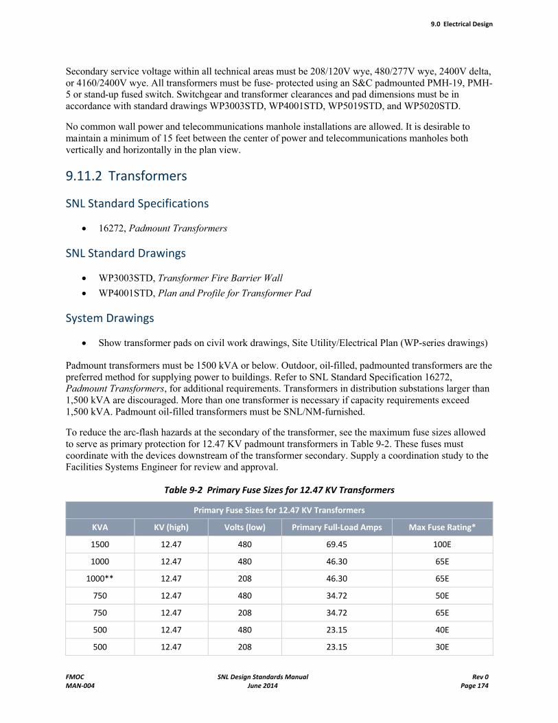
9.0 Electrical Design
FMOC SNL Design Standards Manual Rev 0MAN-004 June 2014 Page 174
Secondary service voltage within all technical areas must be 208/120V wye, 480/277V wye, 2400V delta, or 4160/2400V wye. All transformers must be fuse- protected using an S&C padmounted PMH-19, PMH-5 or stand-up fused switch. Switchgear and transformer clearances and pad dimensions must be in accordance with standard drawings WP3003STD, WP4001STD, WP5019STD, and WP5020STD.
No common wall power and telecommunications manhole installations are allowed. It is desirable to maintain a minimum of 15 feet between the center of power and telecommunications manholes both vertically and horizontally in the plan view.
9.11.2 Transformers
SNL Standard Specifications
16272, Padmount Transformers
SNL Standard Drawings
WP3003STD, Transformer Fire Barrier Wall
WP4001STD, Plan and Profile for Transformer Pad
System Drawings
Show transformer pads on civil work drawings, Site Utility/Electrical Plan (WP-series drawings)
Padmount transformers must be 1500 kVA or below. Outdoor, oil-filled, padmounted transformers are the preferred method for supplying power to buildings. Refer to SNL Standard Specification 16272, Padmount Transformers, for additional requirements. Transformers in distribution substations larger than 1,500 kVA are discouraged. More than one transformer is necessary if capacity requirements exceed 1,500 kVA. Padmount oil-filled transformers must be SNL/NM-furnished.
To reduce the arc-flash hazards at the secondary of the transformer, see the maximum fuse sizes allowed to serve as primary protection for 12.47 KV padmount transformers in Table 9-2. These fuses must coordinate with the devices downstream of the transformer secondary. Supply a coordination study to the Facilities Systems Engineer for review and approval.
Table 9-2 Primary Fuse Sizes for 12.47 KV Transformers
Primary Fuse Sizes for 12.47 KV Transformers
KVA KV (high) Volts (low) Primary Full-Load Amps Max Fuse Rating*
1500 12.47 480 69.45 100E
1000 12.47 480 46.30 65E
1000** 12.47 208 46.30 65E
750 12.47 480 34.72 50E
750 12.47 208 34.72 65E
500 12.47 480 23.15 40E
500 12.47 208 23.15 30E
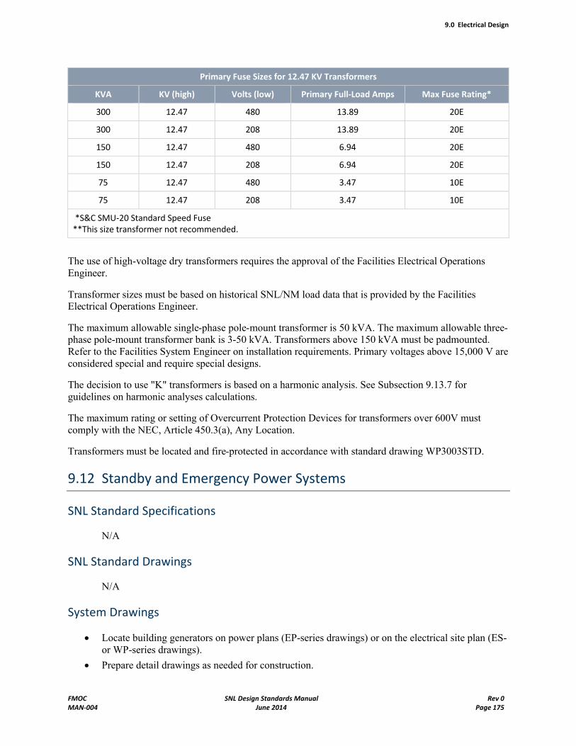
9.0 Electrical Design
FMOC SNL Design Standards Manual Rev 0MAN-004 June 2014 Page 175
Primary Fuse Sizes for 12.47 KV Transformers
KVA KV (high) Volts (low) Primary Full-Load Amps Max Fuse Rating*
300 12.47 480 13.89 20E
300 12.47 208 13.89 20E
150 12.47 480 6.94 20E
150 12.47 208 6.94 20E
75 12.47 480 3.47 10E
75 12.47 208 3.47 10E
*S&C SMU-20 Standard Speed Fuse**This size transformer not recommended.
The use of high-voltage dry transformers requires the approval of the Facilities Electrical Operations Engineer.
Transformer sizes must be based on historical SNL/NM load data that is provided by the Facilities Electrical Operations Engineer.
The maximum allowable single-phase pole-mount transformer is 50 kVA. The maximum allowable three-phase pole-mount transformer bank is 3-50 kVA. Transformers above 150 kVA must be padmounted. Refer to the Facilities System Engineer on installation requirements. Primary voltages above 15,000 V are considered special and require special designs.
The decision to use "K" transformers is based on a harmonic analysis. See Subsection 9.13.7 for guidelines on harmonic analyses calculations.
The maximum rating or setting of Overcurrent Protection Devices for transformers over 600V must comply with the NEC, Article 450.3(a), Any Location.
Transformers must be located and fire-protected in accordance with standard drawing WP3003STD.
9.12 Standby and Emergency Power Systems
SNL Standard Specifications
N/A
SNL Standard Drawings
N/A
System Drawings
Locate building generators on power plans (EP-series drawings) or on the electrical site plan (ES-or WP-series drawings).
Prepare detail drawings as needed for construction.
9.0 Electrical Design
FMOC SNL Design Standards Manual Rev 0MAN-004 June 2014 Page 176
Locate transfer switches, inverters, and feeders on power plan.
Show transfer switches and identify equipment fed from emergency power system on the one-line diagram.
9.12.1 Standby Power
Standby power for Technical Area I is typically provided from the medium-voltage standby generator system. Standby power for all other sites is typically provided by a dedicated diesel generator set. If standby power is determined to be required for an SNL/NM facility, conduct a preliminary standby load study for presentation to the SNL/NM Infrastructure Operations Team (IOT) by the assigned Facilities Electrical System Engineer. The IOT then determines the appropriate source of standby power for the proposed standby power loads.
9.12.2 Emergency Power
Emergency power requirements for all facilities are provided by the facility in question, or by a central utility building (CUB) serving a facility complex. If emergency power is determined to be required, conduct a preliminary emergency load study for presentation to the assigned Facilities Electrical System Engineer who determines the appropriate source of emergency power for the proposed facility. Any new standby or emergency generator systems are to have diesel engines as the prime mover and load banks rated for 100% of the generator output. Once the decision has been made to install a standby or emergency generator system, contact SNL Environmental Management for assistance in obtaining a permit from the U.S. Air Force and the city of Albuquerque. Obtaining a permit may be an extended process.
Automatic transfer switches for standby and emergency power systems must be four-pole switches. For emergency power systems, the automatic transfer switches must have bypass and isolation switches. For standby power systems, evaluate and recommend the need for isolation and bypass switches.
9.12.3 Emergency Lighting Power
Provide inverters for all facilities requiring emergency and egress lighting, except for very small buildings more economically served by battery-powered emergency and egress lights. Inverters are provided by SNL as SFE from the High-Lites product line. Provide the luminaires, space, housekeeping pads, normal power circuits, and distribution circuits required to accommodate the inverters. Design the terminal connections to the inverters with flexible conduit to facilitate inverter servicing. Provide the rated normal power feeders for the respective inverter models shown in Table 9-3.
Table 9-3 Rated Normal Power Feeders by Inverter Model
Inverter Model Full-Load Circuit Rating
1.5 kVA, 120v: HCI-1500-A-P-CTS-OTR-FB-081704 16 amp 20amp
1.5 kVA, 277v: HCI-1500-R-P-CTS-OTR-FB-081704 7 amp 15amp
4.8 kVA, 120v: HCI-4800-A-P-CTS-OTR-FB-012908 50 amp 60amp
4.8 kVA, 277v: HCI-4800-R-P-CTS-OTR-FB-012908 22 amp 30amp
All models must be supplied with battery packs with 48-volt segmentation.
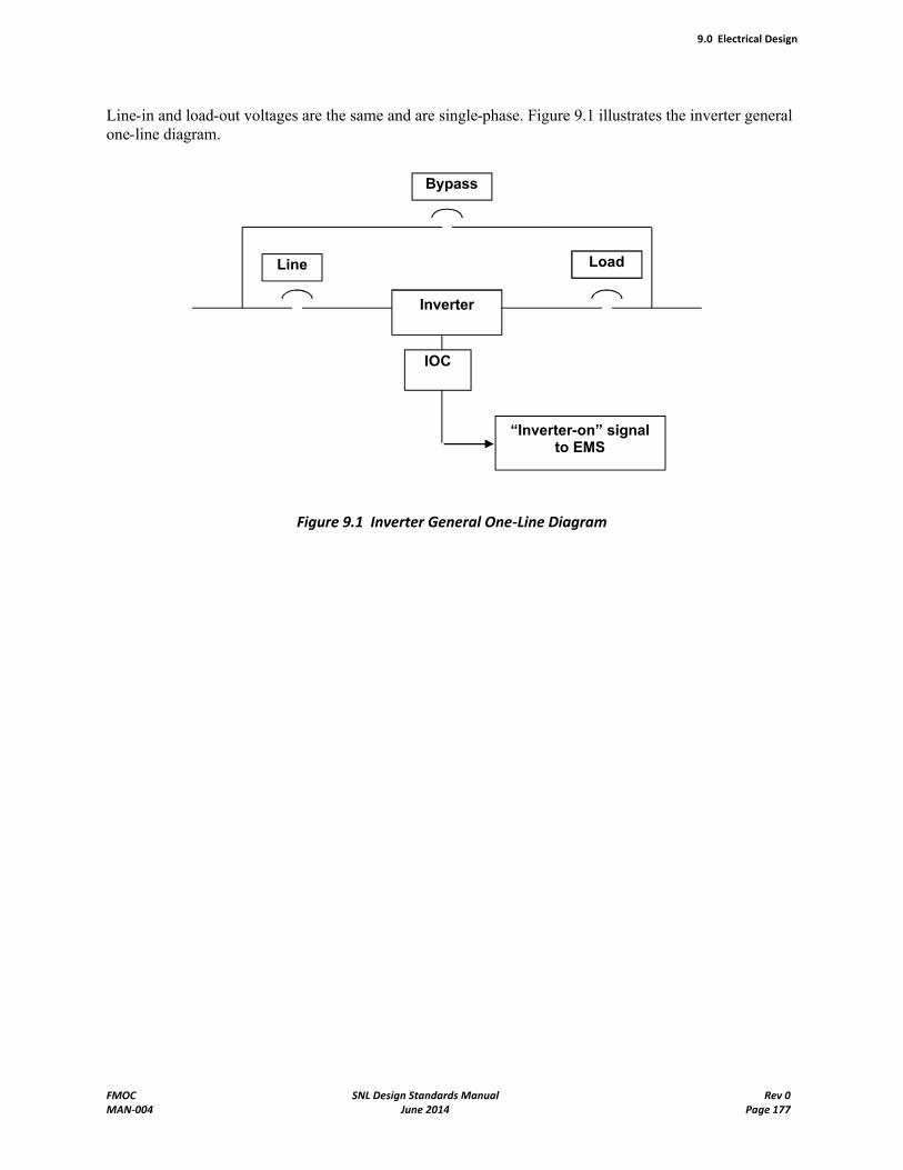
9.0 Electrical Design
FMOC SNL Design Standards Manual Rev 0MAN-004 June 2014 Page 177
Line-in and load-out voltages are the same and are single-phase. Figure 9.1 illustrates the inverter general one-line diagram.
Figure 9.1 Inverter General One-Line Diagram
Inverter
Line
Bypass
Load
“Inverter-on” signal to EMS
IOC
9.0 Electrical Design
FMOC SNL Design Standards Manual Rev 0MAN-004 June 2014 Page 178
9.13 Design Calculations
9.13.1 General
Present all electrical calculations using the guidelines in this section. Provide two 8½-inch by 11-inch, three-hole-bound reports that contain all electrical calculations, time-coordination curves, and protective device settings with final drawing submittal. Provide one-line diagrams and all electronic files with all calculations. During construction support services, before approving any submittal, update calculations based on contractor submittal. Provide a complete set of calculations to the contractor (via RFI process) upon request. Ensure that the manufacturer’s catalog data on the affected protective devices show they have adequate fault current interrupting capacity for the available short circuit current. These calculations should be made available in electronic format to SNL immediately upon request.
9.13.2 Voltage-Drop Calculations
Prepare a complete set of voltage-drop calculations. When both normal and standby primary feeders serve a facility, provide calculations for both feeders. The preferred calculation method is the SKM Systems Analysis Dapper software program.
The maximum allowable steady state voltage drop must not exceed 5% total for building wiring.
The maximum allowable transient voltage drop must not exceed 15% at the utilization equipment. If a problem is identified, notify the assigned Facilities System Engineer for resolution.
Design the standard voltage profile for regulated power distribution systems to comply with ANSI/IEEE Standard 141-1993 (Red Book) or the latest edition.
Calculate voltage drops for the longest-branch circuit to include the drop in feeders, subfeeders, and transformers back to the first bus with automatic regulation (usually the primary master unit substation). Do not use a building transformer to correct secondary voltage drops. Set transformer voltage taps to nominal voltage values under no-load conditions.
Unless loading can actually be predicted, assume the full load for all branch circuits as that limited by the maximum load on the conductors by these standards, applicable codes, or both. The power factor for future loading is considered to be the same as when designed.
9.13.3 Short-Circuit and Arc-Flash Calculations
Prepare a complete set of short-circuit, breaker coordination, and arc-flash calculations. When both normal and standby primary feeders serve a facility, provide calculations for both. The preferred fault-duty calculation method must be SKM Systems Analysis Dapper and Captor software programs. Obtain specific building SKM files as the starting point and update with new project information (when available).
Calculations must consider both bolted three-phase and single-phase-to-ground fault current on secondary systems. State the base MVA or KVA available at the fault. Arc-flash calculations must include the calorie levels, PPE requirements, hazard categories, and boundary dimensions for all equipment that may be serviced or used for troubleshooting while energized. The calculations must include the data necessary
9.0 Electrical Design
FMOC SNL Design Standards Manual Rev 0MAN-004 June 2014 Page 179
to completely execute the information and warning label to be applied to the equipment covers as shown on SNL Standard Drawing E-0006STD.
Prepare protective device coordination graphs that demonstrate that the protective devices are properly coordinated for interrupting faults. Prepare these graphs for all new or modified primary and secondary systems. Also, verify existing equipment settings and provide calculations from new equipment through existing equipment to the service entrance. Curve plots from the software program Captor are an acceptable alternative.
The design must include the use of S&C, SMU-20, 12.47 kV, E-type, standard-speed fuses in 15 kV S&C padmount or stand-up switchgear, unless approved otherwise by the Facilities Systems Engineer.
Additionally, present the manufacturer's catalog data on the affected protective devices to show they have adequate fault-current interrupting capacity for the available short-circuit current.
9.13.4 Wire-Pulling Calculations
When new ducts are required for primary power system (>600V), submit a set of calculations showing the maximum tension placed on the cables during pulling and the maximum allowable tension the cables can withstand. Calculate also, from a pressure standpoint, the force exerted in each elbow or bend during pulling and the radius of each bend. The minimum radius for electrical duct banks is 3 feet. Calculations must be performed in both directions with resultants indicating either direction of pull is allowable. Indicate the resultant radii on the plans, plus the pulling instructions that are required for the method and direction.
9.13.5 Lighting Calculations
Calculate the horizontal illumination levels for each room using the zonal-cavity method described in the Illuminating Engineering Society (IES) Lighting Handbook. Similar-sized rooms may be reported under a single spreadsheet calculation when the illumination level does not vary more than 5% to 10% across the group of rooms. When intense point sources, such as MHID lights, are used for indoor lighting, perform an additional spot check for hot spots and uniformity using the point-by-point method.
Constants, such as lumen output per lamp, fixture efficiency, maintenance factor, or coefficient of utilization, must be shown with the source of the constants identified, such as a product cut sheet. In most cases, the maintenance factors should be chosen on the basis of a medium-intensity maintenance program, full-rated voltage applied, no temperature derating, and a 5% tolerance for lamp burnout. Coordinate expected wall, ceiling, and floor reflectance with architectural finishes, and explain significant excursions from the 80/50/20% standard.
Calculate the vertical illumination level for those rooms and spaces where adequate illumination on walls, display cases and boards, or shelves is important to the mission of the room.
Calculate the visual comfort probability in the manner described in the IES Lighting Handbook for all rooms in excess of 40 feet in length and width, or when directed by the electrical design criteria. Where other than "white light" (low CRI, or significantly off 3,500°K) is used, calculate the human eye response to the spectrum provided, and provide the equivalent effective illumination level had "white light" been used.
Specify the operating point of adjustable automatic switching controllers, such as at what ambient conditions the controllers are to function both on and off. Include delay times and sensitivity settings for
9.0 Electrical Design
FMOC SNL Design Standards Manual Rev 0MAN-004 June 2014 Page 180
occupancy sensors, ambient light levels for daylight-harvesting controls, timer settings, and Facilities Control System interconnections.
Use the point-to-point method to develop isolux curves for design of parking, ground, flood, or perimeter fence lighting systems to design the required horizontal footcandle levels and uniformities at ground level. Submit the isolux curves as part of the design package.
Options for calculations include commercial software programs explained in the IES Lighting Handbook. Identify the program used by trade name and version number.
9.13.6 Exterior Lighting Calculations
Use isolux curves to design ground or fence lighting systems to obtain the required minimum footcandle level, horizontal, at ground level. Submit the isolux curves used for cross-checking.
9.13.7 Harmonic Analyses Calculations
Prepare harmonic study calculations when a significant amount of harmonic (nonlinear) load is added to the distribution or building power system. A harmonic study is also required when the new load exceeds the recommended voltage or current distortion levels as allowed by IEEE Standard 519-1992, IEEE Recommended Practices and Requirements for Harmonic Control in Electrical Power Systems.
The design must include a system that limits the voltage and current distortion at the point of common coupling per the limits recommended by IEEE 519-1992. SNL/NM provides the existing power system information.
The results of the harmonic study dictate when additional harmonic correction measures are required.
9.14 Access and Layout
Electrical equipment must be accessible for periodic maintenance, repair, and replacement. This accessibility includes consideration of NEC 110.26 clearances; paths of entry and egress to and from the clearance space; and the types of maintenance, repair, and replacement that might be needed over the useful life of the equipment.
Anticipate and eliminate head-bumping and tripping hazards.
Locate lighting fixtures so access for relamping and repair activities is maintained.
Prepare elevations of crowded walls, particularly where the mechanical and structural equipment used for the maintenance of electrical equipment is located.
Coordinate information on electrical drawings with structural drawings, so sleeves through walls and floors are accurately detailed and specified.
Coordinate with mechanical and HVAC drawings, so each system properly fits into common spaces.
9.15 Sandia-Furnished Material
Unless specifically indicated in the electrical design criteria, SNL/NM furnishes the following equipment:
Emergency light system inverter

9.0 Electrical Design
FMOC SNL Design Standards Manual Rev 0MAN-004 June 2014 Page 181
S&C switchgear
Oil-filled padmounted transformers (primary >600 volts)
9.16 Acceptance Testing
Acceptance testing is required on all new electrical equipment prior to energizing it and placing it into service. Testing must be performed by a third-party testing firm, meeting all qualifications stated in the latest edition of the ANSI/InterNational Electrical Testing Association (NETA) document, ANSI/NETA Standard for Acceptance Testing Specifications for Electrical Power Equipment and Systems. Also, all acceptance testing must be performed in accordance with the latest edition of ANSI/NETA Standard for Acceptance Testing Specifications for Electrical Power Equipment and Systems.

10.0 Telecommunications Design
FMOC SNL Design Standards Manual Rev 0MAN-004 June 2014 Page 182
10.0 Telecommunications Design
Design the telecommunications systems per the separate Telecommunications Systems Design Manual, as available in its most current revision date on Sandia's Engineering Standards website.
Note that the Telecommunications Systems Design Manual applies only to the building's telecommunications equipment and its performance. References in that Manual are made to numerous building systems such as HVAC and power, and provide the performance requirements for those systems as they affect telecommunications. However, such building systems remain under the responsibility of the FMOC, and adequate design for access, compatibility with other building systems, and similar requirements listed in the FMOC Design Standards Manual must be provided. In the event that different requirements for such building equipment are identified between the two Manuals, the FMOC Design Standards Manual shall take precedence.
Ownership of this Chapter of the Design Manual rests in Sandia department 9334, Network Systems Design and Implementation, and department 9335, Corporate Computing Infrastructure and Support Operations. Contact Mike Schalip, (505) 844-6789, mail stop 0788, [email protected], for network engineering support. Contact Patrick Manke, (505) 844-6792, mail stop 0832, [email protected], for telecommunications engineering support. Contact the Telecommunications Trouble Desk, (505) 845-8509, for all other questions.
11.0 Security Design
FMOC SNL Design Standards Manual Rev 0MAN-004 June 2014 Page 183
11.0 Security Design
NOTE Unless specifically stated, the names of the organizations, teams, projects, program, and job titles described in this chapter should be assumed to be internal entities at Sandia National Laboratories in New Mexico (SNL/NM).
11.1 Introduction
This chapter of the Design Standards Manual (DSM) provides guidance to ensure that appropriate physical security considerations are included in the design of new facilities. It describes security construction requirements that must addressed during the design and construction phases of any project. This chapter is co-owned by both Physical Security and Technical Security Systems (TSS) with final approval resting with the Cognizant Security Authority (Center 4200 Director).
11.2 Interface with Safeguards and Security
According to Facilities Management and Operations Center (FMOC) procedure FAC100.3.1, ConductMajor Renovation Projects, security system modifications, no matter how small, must be coordinated with Center 4200 (Security and Emergency Management or S&EM) through the Safeguards Security Request (SSR) process in Maximo. Additionally, as described in ISS100.3.1, Report Personnel Security Information; Security Incidents; and Waste, Fraud, and Abuse, unauthorized modifications to security components, infrastructure, or systems, including unscheduled power outages, are DOE-reportable security incidents.
As part of the SSR process, S&EM Managers review and then approve or deny changes to add, modify, or remove security features to any area, building, room, or structure. In turn, the Technical Security Change Control Board is responsible for reviewing and then approving or denying changes to the security alarm system at SNL/NM. Approved projects receive a formal SSR work authorization response package that authorizes security resources to be involved in a project. As part of the package, an S&EM Project Lead is assigned as the central point of contact for all project-related coordination. The S&EM Project Lead, in most cases, is a member of TSS or Physical Security. The S&EM Project Lead forms an integrated S&EM Project Team to work with the FMOC Project Manager (FPM). All communications and requests should go through the S&EM Project Lead, who then directs the appropriate team member.
For an authorized project, FPM, contractors, and employees must do the following:
Communicate with and through the assigned S&EM Project Lead for additional design and coordination information.
Consult with the S&EM Project Lead for intrusion alarm (IA) sensor layout inside a Closed Area.
Request, through the S&EM Project Lead, the current approved equipment list from the TSS Representative for each project. Do not use lists from past projects, since the approved equipment list is updated regularly. The TSS Representative selects and specifies the approved equipment for each project.
Participate in design reviews and coordinate changes as follows:
- Review the designs with the assigned S&EM Project Lead and S&EM Team upon the completion of the Title II design.
11.0 Security Design
FMOC SNL Design Standards Manual Rev 0MAN-004 June 2014 Page 184
- Formally document each design change recommended by the S&EM Project Lead and S&EM Team as accepted or rejected.
- Formally document the final acceptance of the design as directed by the SNL/NM FPM and the S&EM Project Lead: Provide a complete set of as-built drawings to the S&EM Project Lead and S&EM Team (1) upon completion of the design for new work, removals, or the relocation of any component; and (2) as construction Change Orders modify the original design.
11.3 Security Area Boundaries
11.3.1 Design Philosophy
Security Areas (SAs) are used to protect safeguards and security interests and government property. The SAs described in this subsection are Property Protection Areas (PPAs) and Limited Areas (LAs). Designs for other SAs, such as Protected Areas (PAs) and Material Access Areas (MAAs), are not common and require close coordination with the S&EM Center; therefore, PAs and MAAs are not covered in this manual.
This section identifies specific SA design standards to ensure the areas meet the requirements of several DOE and NNSA policies. As part of the overall security system, additions and modifications to an SA must be coordinated with the S&EM Center through the SSR process prior to design. S&EM management determines whether the security system can support the proposal.
11.3.2 Security Area Stand-off
When designing new facilities, FMOC Systems Engineers and external architectural and engineering (A/E) Engineers and Designers must consider the 30-meter stand-off distance imposed by DOE Manual (M) 470.4-1 Change 1, Safeguards and Security Program Planning and Management (for SECON 3). If this stand-off distance cannot be met for either limited space or per customer request, contact Physical Security for further guidance.
11.3.3 Sound Attenuation Properties for Classified Areas
Buildings, offices, and conference rooms where classified discussions may occur must be designed to meet the following graded Sound Transmission Class (STC) ratings:
Classified Work/Discussion Area – Minimum STC of 35. These areas consist primarily of office spaces where classified discussions occur on an infrequent basis and are not amplified.
Classified Meeting/Discussion Area – Minimum STC of 40. These areas consist primarily of office spaces that accommodate small meetings, classified discussions on a frequent basis, or employ the use of a speaker phone.
Classified Auditorium/Conference Room – Minimum STC of 50. These areas consist primarily of conference facilities or meeting areas designed to accommodate numerous classified discussions or rely on sound amplification for speakers or presenters.
Although instrumented testing can determine precise values, STC values are typically measured subjectively at a standoff distance of one half the distance from the area perimeter to an adjacent wall or at 6 feet, whichever is less.
11.0 Security Design
FMOC SNL Design Standards Manual Rev 0MAN-004 June 2014 Page 185
11.3.4 PPA Boundary
General Requirements
Property Protection Areas are created for the following security interests or activities:
Nuclear materials requiring safeguards controls or special accounting procedures (Category IV special nuclear materials or SNM)
Property of significant monetary value (contents greater than $5M)
Site-identified essential facilities
C4 (command and control, computing, communications) facilities
Facilities containing property inherently dangerous to others
Facilities storing arms, ammunition, or explosives
Facilities housing hazardous material meeting certain conditions (Contact Physical Security for further information.)
NOTE If such a facility is located within a fenced compound, preference is given to extending the PPA boundary to the compound perimeter, except where contraindicated because of operational requirements or undue expense.
Property Protection Areas are established to protect government-owned property against damage, destruction, and theft. Barriers and associated access controls must be installed to control public access.
Barrier design must control, impede, or deny access to an SA. The barrier may include fences and building perimeters. Although fences are not required for PPAs, three-strand barbed wire fences are often used in outlying open areas; however, standard fencing equal to LA fence requirements is appropriate for protection of personnel and government property. Contact the assigned Physical Security representative for facility characterization and PPA barrier requirements.
Temporary fencing for PPA boundaries must be installed when the fencing is affected by construction activities; however, temporary fencing must comply with the protection goals and operational requirements established for the affected PPA. Physical Security must conduct a design review for all temporary fences.
Signage
All signs must be in compliance with the Sign Standard for Interior/Exterior/Civil/Regulatory/Physical Security Signs.
The following signs must be posted as described:
"No Trespassing" signs at PPAs boundaries along the following:
- Building, turnstile, and gate entrances
- External building walls without an entrance, at least one per wall
- Fence or boundary, at least every 200 feet
"Prohibited Articles" signs at PPA boundary gates, turnstiles, and main entrances to buildings.
11.0 Security Design
FMOC SNL Design Standards Manual Rev 0MAN-004 June 2014 Page 186
"Video Surveillance" signs (if installed) at PPA boundary gates, turnstiles, and main entrances to buildings.
"Atomic Weapons and SNM Rewards Act" signs at gates, turnstiles, and main entrances to buildings.
11.3.5 LA Boundary
General Requirements
Permanent LAs at SNL are established for the following security interests or activities:
Use, processing, or storage of Category III Accountable Nuclear Material (ANM)
Protection of classified matter
Permanent physical barriers must be installed to identify the boundary of an LA. Physical barriers must beinstalled to deter unauthorized access. Barriers must be designed to direct the flow of personnel and vehicular traffic through designated entry control points. Additionally, designs must ensure that overhead utilities do not pass into the LA without physical protection, and elevators that penetrate the LA must beprovided with an Access Control System (ACS).
Fenced LA Boundaries
Fences must be installed in accordance with the standard specifications and drawings described in Chapter 3, "Civil Design Standards." Fences must be installed as follows:
For standard security fence fabric, use a 2-inch-square or smaller mesh of No. 11 American wire gauge (AWG) galvanized steel or heavier steel wire.
- Use wire ties to fasten fence fabric to poles. The ties must be of equal tensile strength to that of the fence fabric. The use of aluminum ties or fence fabric is prohibited.
- Seek approval to use alternative fencing materials. Alternative materials may be approved for use in lieu of the standard security fencing; however, the penetration resistance must be the same or greater than the resistance of the standard security fence. Contact the S&EM Project Lead and request a consultation with the Physical Security representative prior to using nonapproved alternative fencing. Alternative fencing materials must be approved by the Cognizant Security Authority prior to use.
Ensure overall fence height, excluding outriggers and barbed wire or barbed tape coil topping, is at least 7 feet. See Chapter 3, "Civil Design Standards," for details.
Install the fence no less than 20 feet from the building or security interest being protected. If this distance is not possible, contact the Physical Security representative. During the consultation, the representative determines supplementary protective measures that must be applied, such as extending the fence height.
Establish a 10-foot clear zone along each side of the security fence to facilitate intrusion detection and assessment.
Landscaping or utilities cannot be installed within 10 feet of either side of the security area fence.This requirement ensures the clear zones are clear of vegetation, equipment, and other objects that could impede observation or facilitate bridging. If this is not possible, contact the S&EM Project Lead and request a consultation with the Physical Security representative.
Install fence posts, bracing, and other structural members on the high-security side of the fence.
11.0 Security Design
FMOC SNL Design Standards Manual Rev 0MAN-004 June 2014 Page 187
Install the fence so the bottom of the fence is no greater than 2 inches from firm ground. If the soil is unstable or subject to erosion, extend the fence below the surface.
Ensure vertical gaps do not exceed 6 inches in width at any point, from the ground to the top of the fence, where the fencing meets gates, turnstiles, or other structures constituting the LA boundary.
Secure the gate hardware by brazing, peening, welding, or applying an epoxy that prevents removal of hardware accessible from outside the security area.
Stabilize surfaces in areas where loose sand, shifting soils, or surface waters could cause erosion.
- Suspend additional fencing from the lower rail of the main fence for elevation changes and depressions that can be stabilized, but cannot be leveled.
- Provide concrete curbs, sills, or a similar type of anchoring device extending below ground level if surface stabilization is impossible or impractical.
- Block areas subject to water flow under security fencing with wire or metal bars that not only provide for the passage of floodwater, but also a penetration delay equal to that of the security fence.
The following signs must be posted on the LA fencing:
"No Trespassing" signs at all entrances and every 200 feet along the fence, if the LA boundary is not within a posted PPA boundary.
"Prohibited/Controlled Article" signs at main entrances.
"Video Surveillance" signs (if applicable) at main entrances.
"Atomic Weapons and SNM Rewards Act" signs at main entrances.
Proposals for using temporary fencing must be coordinated with the S&EM Project Lead and Physical Security representative to ensure the fencing complies with the SAs protection goals and operational requirements. Proposals for temporary fencing must be reviewed and authorized by Physical Security.The Physical Security representative must also conduct a design review for all temporary fencing projects.
Turnstiles
The FMOC (4800) takes responsibility for gates and turnstiles and their designs and locations. Turnstiles must be designed and integrated into the security area boundary in a manner that prevents its use as a climbing aid to breach the perimeter. For a turnstile, specify the following:
Two, full-height, single security turnstiles configured side by side to allow both entry and exit from an area.
Turnstile equipment from the standard drawing.
A security bypass gate at all turnstile locations.
All proposed turnstile locations must be coordinated with the assigned S&EM Project Lead and S&EMTeam.
Buildings as the LA Boundary
Most standard building materials, as specified in Chapter 3, "Civil Design Standards," and Chapter 6, "Architectural Design Standards," meet security requirements when selected and designed for penetration
11.0 Security Design
FMOC SNL Design Standards Manual Rev 0MAN-004 June 2014 Page 188
resistance to and evidence of unauthorized entry into the LA. All LAs must meet the following additional design requirements:
Walls
- Extend from the true floor to the structural ceiling.
- Use insert-type panels that cannot be removed from outside the LA without showing visual evidence of tampering.
Doors
- For doors constructed with transparent glazing material, offer penetration resistance to and evidence of unauthorized entry into the area.
- For doors that allow potential visual access to classified, install a sight baffle.
- For storefront-type doors, ensure the door is capable of retrofit with the electric strike as required for the ACS.
- For doors with external hinges outside of the LA, ensure the door hinges have nonremovable hinges/pins.
- For outward-swinging doors, if it is possible to manipulate the door latch, install a latch guard. Ensure the latch cannot be removed from the outside.
- Install an astragal or mullion along the full length of the door where doors are used in pairs.Ensure the astragals or mullions are reinforced and not removable from outside the LA.
- Ensure emergency and evacuation exits do not include hardware that allows access from outside the LA.
- For doors with an emergency panic device, ensure panic bars cannot be “dogged down.” These are normally considered fire-rated panic devices.
- Do not use magnetic locks because of conflicts between fire code and security requirements.
Windows
- Ensure windows are fixed (nonoperable) and panes cannot be removed from the outside in LA boundaries.
- For windows that allow potential visual access to classified, install a sight baffle over the window.
Openings
- Ensure all openings greater than 96 square inches and greater than 6 inches at its smallest dimension (or circular openings greater than an 11-inch diameter) that penetrate the LA boundary (for example, ductwork and utility chases), are protected. Use physical protection with 18-gauge (or greater) expanded metal or ½-inch rigid steel bars, welded vertically and horizontally 6 inch on center, to provide the necessary barrier delay.
- If barriers cannot be installed, protect the opening with IA sensors.
- If the opening is movable, protect the opening with IA sensors.
Signage
Post the following signs on buildings that are part of an LA boundary:
- "No Trespassing" signs at all entrances and at least one sign on each side of the building without an entrance, if the LA boundary is not within a posted PPA boundary.
- "Prohibited and Controlled Article" signs at main entrances.
11.0 Security Design
FMOC SNL Design Standards Manual Rev 0MAN-004 June 2014 Page 189
- "Video Surveillance" signs (if applicable) at main entrances.
- "Atomic Weapons and SNM Rewards Act" signs at main entrances, if the LA boundary is not within a posted PPA boundary.
11.3.6 Security Area Entry Point Lighting
Lighting at Security Area entry points must meet the following requirements:
It must enable assessment of unauthorized activities, persons, or both, at pedestrian and vehicular entrances and allow examination of DOE security badges and inspections of personnel, hand-carried items, packages, and vehicles.
It must be positioned so PF personnel are not spotlighted, blinded, or silhouetted by lights. The lighting placement and design should enhance, not minimize, PF night-vision capabilities.
11.4 Vaults and Closed Areas
11.4.1 Design Philosophy
Vaults and Closed Areas are used to store safeguards and security interests and located within an LA.This section describes vault and Closed Area design standards, so they meet DOE requirements. Except where otherwise stated, the term "Closed Area" includes vaults. Since DOE requirements often change and affect existing installations, these standards were developed to provide the most cost-effective implementation for the life cycle of a vault or Closed Area. Any proposed designs that do not conform to these design standards must be approved by the S&EM Center through the SSR process. Because of an effort to reduce the numbers of vaults and Closed Areas at SNL/NM, requests for new vaults and Closed Areas must have sufficient approved justification.
11.4.2 Vault Construction
Vault construction standards must comply with Federal Standard 832, Construction Methods and Materials for Vaults. Vaults must be constructed to meet construction requirements in NNSA Administrative Policy (NAP) 70.2, Physical Protection, Chapter IX, "Secure Storage." A vault is apenetration-resistant, windowless enclosure that has doors, walls, floor, and roof/ceiling designed and constructed to significantly delay penetration from forced entry and equipped with IDS devices on openings allowing access. The material thickness must be determined by the requirement for forcible entry-delay times for the S&EM interests stored within, but must not be less than the delay time provided by a minimum 8-inch-thick reinforced concrete poured in place, with a minimum 28-day compressive reinforced strength of 2,500 pounds per square inch.
If 8-inch-thick reinforced concrete is not used, vault designs and calculations must be constructed to meet an equivalent penetration delay. TSS must approve the alternate design and associated delay calculations.Rooms that do not meet the equivalency requirement must be installed per Closed Area construction requirements.
A vault door and frame must meet the highest level of penetration resistance of the General Services Administration (GSA). The lock on the door must be a minimum of a GSA-approved lock. Vault doors protecting classified matter must have a lock that meets Federal Specification FF-L-2740A, "Locks, Combination." Kaba Mas X-08™ or X-09™ combination locks are the only locks that meet these requirements. Locks must be installed by the SNL-designated locksmith. The Lockmasters, Inc.
11.0 Security Design
FMOC SNL Design Standards Manual Rev 0MAN-004 June 2014 Page 190
LKM7003, "Life Safety Exit Device," is the only DOE-approved device that can be installed with the X-09. If the LKM7003 is not installed, establish administrative controls for the activation of the "Life Safety Pin" on the XO-series locks that meet requirements in NFPA 101, Life Safety Code.
Vault doors protecting unclassified weapons or ammunition may use either an approved combination lock, internal locking device (ILD), or padlock. Combination locks protecting weapons and ammunition must meet the requirement of Underwriters Laboratories (UL) Standard, UL 768, "Combination Locks,"Group 1 or Federal Specification, FF-L-2937, "Combination Lock, Mechanical." If using an ILD or padlock, contact Physical Security for further guidance and specifications.
Install a balance magnetic switch (BMS) on all doors and openings that allow access to or egress from vaults that alarm at the Security Command Center (SCC).
Vaults equipped with automated access control must have the override lock rekeyed to a Level III lock by the SNL-designated locksmith.
Vaults are constructed with only one entry door unless additional doors are needed to meet requirements in NFPA 101, Life Safety Code. However, the locking hardware on the egress or service doors must still meet the lock and penetration delay requirements.
11.4.3 Closed Area Construction
Closed Areas must be constructed to meet the construction requirements in NAP 70.2, Physical Protection, Chapter IX, "Secure Storage." A Closed Area is an area that meets the requirements of NAP 70.2, Physical Protection, for safeguarding classified matter, a security interest, or both, that, because of size, nature, or operational necessity, cannot be adequately protected by the normal safeguards or stored during nonworking hours in approved containers. A BMS and volumetric coverage must be used on each door or engineered opening to allow detection of attempted or actual unauthorized access. Historically, DOE requirements for Closed Areas were established for storage of classified matter and not necessarily for human occupancy; therefore, optimum construction is for small windowless enclosures that are of substantial construction and without penetrations greater than 96 square inches. Closed Areas differ from vaults in that intrusion-detection coverage is required to detect penetrations through engineered openings (those openings designed and constructed to allow access to storage locations [for example, a door]).
Closed Area construction must offer substantial resistance to unauthorized entry into the area. The Closed Area design must consider the types and configuration of classified matter or assets that may be stored within the Closed Area throughout its use. Tradeoffs may be made between the physical features of the Closed Areas and the sensor coverage; however, the initial sensor coverage design may not address all future Closed Area configurations nor easily address future changes in requirements.
The perimeter walls, floors, and ceiling must be permanently constructed and attached to one another. All construction must provide visual evidence of unauthorized penetration. The following standards are required for all new construction, modifications, and repairs of existing areas:
Walls
Except as allowed, the walls must be windowless and constructed of brick, concrete, or corrugated metal, optimizing the usable wall space within the Closed Area. Storage of and the potential future storage of classified matter on or near the wall requires either an adequate physical barrier or intrusion detection between the asset and the wall consistent with that required to remove or compromise the asset.
11.0 Security Design
FMOC SNL Design Standards Manual Rev 0MAN-004 June 2014 Page 191
Walls must be constructed to extend from the true floor to true ceiling. For more information, see also the design information on "Ceilings and Floors."
Wall design must minimize the number of penetrations. Incorporate supplemental barriers if any penetrations are greater than 96 square inches (or 6 inches on one side). For more information, see "Other Openings/Penetrations."
Ceilings and Floors
When a false ceiling is required below the true ceiling or roof pan, the false ceiling must be constructed of material offering resistance to and detection of unauthorized entry. Wire mesh or other nonopaque material offering similar resistance to, and evidence of, unauthorized entry into the area may be used if visual access to classified matter is not a factor. If visual access is a factor, all windows, which might reasonably afford visual surveillance of personnel, documents, materials, or activities within the facility, shall be made opaque or equipped with blinds, drapes, or other coverings to preclude such visual surveillance. For a visual access area that cannot be equipped with blinds or other coverings, then barriers shall be installed to provide protection against unauthorized visual observation.
Acoustic lay-in (suspended) ceilings may be installed below the true ceiling. Because of the resulting interstitial space, the Technical Security Systems Representative must evaluate the protected asset and penetrations to determine if sensor coverage is required, and may require sensors within the interstitial space.
Alternatively, a suspended ceiling with ceiling tile clips may be installed. If ceiling tile clips are used, a minimum of four clips must be installed per ceiling tile. The clips must be installed from the interior of the area, and each clip must be mounted to preclude surreptitious entry. Penetrations greater than 96 square inches through the clipped ceiling must be protected by securing to the ceiling grid or to a supplemental barrier.
When wall barriers do not extend to the true ceiling and a false ceiling is created, the false ceiling must be reinforced with wire mesh or 18-gauge expanded metal to serve as the true ceiling. Or, the ceiling tiles must be secured using another appropriate method (for example, clips or caulking).
Ceiling tiles must not span Closed Area boundary walls. Design of suspended ceilings must ensure ceiling tiles at walls are large enough for tile clip installation. For modifications to existing Closed Areas with tiles that do not have a support grid, four tile clips must be installed, if the tile is large enough. Additional clips must be required in the following circumstances:
Three sides have supports; use two clips on one side.
Two sides have supports; use two clips per side, and install two clips as close to the wall as possible.
A tile is not large enough for four clips; install as many clips as possible. Apply adhesive caulk between the tile and the support on the sides without clips.
Access, or raised, flooring may be installed above the true floor to allow for computer or other cabling.Because of the resulting interstitial space, the Technical Security Systems Representative must evaluate the protected asset and the protection of penetrations to determine if sensor coverage is required within the interstitial space. When the interstitial space is greater than 6 inches between the false floor or ceiling, the Closed Area program must use the following criteria to determine if alarming is required:
Open storage (covered/shielded)
11.0 Security Design
FMOC SNL Design Standards Manual Rev 0MAN-004 June 2014 Page 192
Classified discussions (intermittent, not scheduled)
No access to adjacent uncontrolled space
If any or all of the above apply, no alarms are required in the interstitial space. This includes Technical Surveillance Countermeasure (TSCM) considerations. The protected interests are considered when not installing sensors between the true floor or ceiling and the false floor or ceiling.
Doors
Specify a solid-core wood door (minimum 1.75-inch thick) or a metal door of substantial construction.The doors for a Closed Area must be installed as follows:
Install only one entry door at the entry control point.
Install an X-08 or X-09 combination lock with the Lockmasters Inc. LKM7003 "Life Safety Exit Device" on the entry door. The LKM7003 is the only DOE-approved device that can be installed with the X-09. If the LKM7003 is not installed, establish administrative controls for the activation of the "Life Safety Pin" on the XO-series locks that meet requirements in NFPA 101, Life Safety Code. The LKM should be configured so that the doors swing outward only.
Aligned and installed without gaps or openings on any side.
For paired doors, install overlap molding (astragal) for the length of the doors where the doors meet.
Secure windows, service panels, door louvers or baffle plates, or similar openings with 18-gauge expanded metal fastened securely on the inside of the Closed Area.
A Closed Area must be designed with the minimum number of service and emergency egress portals.During the renovation of an existing Closed Area, remove any unnecessary doors. For new construction of a Closed Area with an asset that is or might be visually classified, windows are not allowed. For renovations, replace any doors having windows with solid doors. At a minimum, install a sight baffle (for example, blinds or shades) over the windows.
Minimize the use of other egress or service doors. Egress or service doors, without the X-08 or X-09 combination lock, may have an electric strike for automated entry, but must have substantial locking hardware accessible only from inside the Closed Area. Install egress doors only as required by NFPA 101, Life Safety Code. Install service doors and roll-up doors only when operationally required and approved by Physical Security.
Closed Area doors must be equipped with eyebolts, which must be used for the application of security seals, as required. The eyebolts must be as follows:
1-inch long with a minimum 0.4375-inch opening and 2.25-inch rod
Compliant with the fire ratings of the door or frame
Mounted on doors approximately 1.5 inch from the edge
- For single doors, one welded onto the door and one on the door frame, such that either bolt cannot be rotated. Mount one eyebolt vertically (with a 90 degree angle between the twoeyebolts) and no more than 2.5-inch center-to-center from the other eyebolt.
- For double doors, mount one eyebolt horizontally and the other eyebolt vertically, with 54 inches (±3 inches) above the finished floor.
Welded on the door frame and located in the center of the molding horizontal to the floor. Ensure the eyebolts cannot be rotated.

11.0 Security Design
FMOC SNL Design Standards Manual Rev 0MAN-004 June 2014 Page 193
- For single doors, weld an eyebolt on the door and another on the door frame.
- For double doors, weld one eyebolt to each door.
Sealing Closed Area Doors
Closed Areas are designed with a minimum number of service and emergency egress portals. They have egress doors as required by life safety codes. Service doors and roll-up doors exist within Closed Areas only when operationally required and approved by Technical SecuritySystems.
Fire Protection: An exit door may be sealed as long as the required common path of travel of 100feet is not exceeded, and it is permitted to be blocked by the International Building Code (IBC).The sealed door must have a "no exit" sign posted above the door to notify the occupants that the door is not operational.
In areas used or occupied as a high-hazard operation (Groups H-1, H-2, and H-3), the common path of egress travel must not exceed 25-feet.
In areas used or occupied as a high-hazard operation (Groups H-4 and H-5), a single exit is permitted with a maximum occupant load of 10 persons.
In areas used or occupied as an office, storage or utility, and miscellaneous operation (Groups B, S, and U), a single exit is permitted with a maximum occupant load of 29 persons.
Securing Metal Doors
For inward-swinging doors:
Tack-weld a 5-inch bead (length of the hinge) at each hinge on the inside of the door.
Tack-weld a 5-inch bead on the opening side, one above and one below the latch on the inside of the door.
For outward-swinging doors:
Tack-weld a 5-inch bead (length of the hinge) at each hinge on the outside of the door.
Tack-weld a 5-inch bead on the nonhinged side of door, one above and one below the latch on the outside of the door.
NOTE Paint the welds to match the color of the door.
Securing Wood Doors
Use a metal cross bar with 3/8 minimum bolts anchored to wall. The cross bar must be 1” x 3/16” minimum thickness and installed on the inside of door.
Door Locks and Door Hardware
Closed Area doors must have locks that meet Federal Specification, FF-L-2740A , "Locks, Combination." Only the Kaba Mas X-08 or X-09 combination locks meet this requirement. Locks must beinstalled by the SNL-designated locksmith.
11.0 Security Design
FMOC SNL Design Standards Manual Rev 0MAN-004 June 2014 Page 194
Heavy-duty builder's hardware must be used and securely fastened to preclude surreptitious removal and to ensure visual evidence of tampering. Nonremovable pin (NRP) hinges must be installed on Closed Area hardware accessible from outside the area. The NRP hinges must be pinned, brazed, or spot-welded to preclude removal.
Deadbolts with an interior handle-operated release or other locking mechanisms must be of heavy-duty builder's hardware and meet requirements in NFPA 101, Life Safety Code.
Only approved panic hardware (for example, the LKM7003) must be linked to the spin-dial lock. Panic hardware or lever latch sets on emergency doors must be operable only from the inside and must not have exterior hardware.
When automated access control with an electric strike is installed, the door locking mechanism mustinclude an appropriate Security Level III lock installed by the SNL-designated locksmith.
Roll-Up Doors
The use of roll-up doors must be limited to Closed Areas that require the movement of large items in and out of the Closed Area. Closed Areas must not be constructed at existing locations with roll-up doors, unless the door is replaced with a hard wall or is required for the Closed Area mission. Roll-up doors must be as follows:
A minimum of 26-gauge galvanized steel, interlocked together to form a continuous curtain with interior and exterior polypropylene wear strip for the full height of the door.
Equipped with a bulb astragal and bottom weather strip on the bottom bar of the door to ensure closure and fit along the floor. The bottom bar of the door may be made of reinforced aluminum.
Equipped with two 10-gauge (minimum) slide locks, one on each side, that lock from the interior of the Closed Area.
Equipped only with an interior roll-up door electric operator, including controls. See Chapter 6, "Architectural Design Standards"; Section 6.3, "Architectural Design Requirements";Section 6.3.4, "Interiors"; and Section 6.3.4.3, "Doors," for more information.
Windows
As much as possible, windows must not be used in Closed Area designs. Windows that open must not be used in new construction designs. Windows must meet the following requirements:
For renovations in which a window opens, the window must have either 0.5-inch rigid steel bars, welded vertically and horizontally 6 inches on center, or minimum 18-gauge expanded metal installed, such that the barrier cannot be removed from outside the area of protection.
Window frames must be securely anchored in the walls, or installed in fixed (nonoperable) frames, such that the panes cannot be removed from outside the area under protection.
When the Closed Area stores visually classified assets, install visual baffles, such as blinds or shades on windows.
Other Openings and Penetrations
Openings greater than 96 square inches and greater than 6 inches at the smallest dimension, (greater than an 11-inch diameter) must be protected. Use a minimum 18-gauge expanded metal or 0.5-inch rigid steel
11.0 Security Design
FMOC SNL Design Standards Manual Rev 0MAN-004 June 2014 Page 195
bars, welded vertically and horizontally 6 inches on center, to provide the necessary barrier delay. If barriers cannot be installed, intrusion detection must be provided to protect the opening.
Circular openings greater than 11-inches in diameter must be protected by minimum 18-gauge expanded metal or 0.5-inch rigid steel bars, welded vertically and horizontally 6 inches on center, to provide the necessary barrier delay. If barriers cannot be installed, intrusion detection must be provided to protect the opening.
Air supply and return ducts must be installed such that an adversary cannot crawl into the Closed Area undetected. (See also Chapter 8, "Mechanical Design Standards," Section 8.3, "Access and Layout,"Section 8.3.2, "Security Requirements.") Openings and penetrations must meet the following requirements:
Equip duct penetrations with barriers installed at the Closed Area boundary for penetrations larger than 96 square inches in area and more than 6 inches in the smallest dimension or greater than an 11-inch diameter. Ensure penetrations (for example, lights, diffusers, and air return grids) are secured to the ceiling brackets or tiles or have a supplemental barrier installed.
Penetrations less than 96 square inches or less than an 11-inch diameter are acceptable without additional protection.
If standard physical options are not possible to protect a penetration, contact the Technical Security Systems Representative to obtain approval for the installation of intrusion-detection sensors.
11.5 Construction Standard Specifications
When making any changes to the security system, review the follow specifications and drawings for general guidance and an overall understanding of how the system is constructed:
Construction Standard Specifications
- 16720, Intrusion Alarm System
- 16725, Access and Entry Control
- 16742, Intra-Building Telecommunications System (for optical-fiber media only)
TSS standard drawings
Contractors and employees must request access to sections 16720 and 16725 from the Facilities Project Manager and demonstrate need-to-know (NTK) for this material. To request access to restricted S&EMspecifications and drawings, contact the SSPC. Once access is granted to these items, contractors and employees must implement the appropriate levels of protection in accordance with corporate process IM100.2, Manage and Protect Information, and corporate procedure IM100.2.5, Identify and Protect Unclassified Information.
11.6 GEDII System Design
Systems Engineers in FMOC and external architectural and engineering (A/E) Engineers and Designers generally must limit a design to the following:
Equipment and cabling as specified by TSS-approved equipment list, TSS-approved standards, and/or the SSPC
Selecting, specifying, and laying out cabinets and boxes per TSS requirements
11.0 Security Design
FMOC SNL Design Standards Manual Rev 0MAN-004 June 2014 Page 196
Selecting, sizing, and laying out raceways (conduits) per TSS standard cable callouts
Selecting and specifying cables (media) that are to be pulled in
Identifying and providing dedicated 120VAC circuits as needed to power equipment
In addition, system engineers and A/E engineers must ensure that any optical-fiber media specified on any project is terminated, tested, and certified in accordance with SNL Standard Specification, 16742, Intra-Building Telecommunications System.
Furthermore, Systems Engineers and A/E Engineers must consult and gain approval for the system configuration with the SSPC and S&EM Team at each step in a design process. The SSPC and S&EMTeam provide technical oversight and ensure that only approved equipment and materials are selected and properly installed. Equipment substitutions and "or equal to" specifications are not allowed.
11.6.1 Autonomous Control Unit Cabinet
An Autonomous Control Unit (ACU) cabinet can manage up to 10 alarm points (for example, motion sensors and emergency exit doors with BMS sensors) that may be home-run to and terminated in the cabinet. An ACU can also handle a total of 16 devices (for example, readers and Remote Input Module or RIM cabinets), but no more than 8 RIMs. If an additional ACU is needed to handle the sensors and devices in a Closed Area, mount the ACU inside the Closed Area.
Specify the following for the ACU cabinet:
30- x 24- x 6-inch NEMA 1 cabinet (Hoffman catalog number A30N24ALP or an appropriate outdoor cabinet from the current TSS equipment list)
4-inch square junction box with a NEMA 5-20R 20A (120VAC, double duplex receptacle) in the lower-left corner of the ACU cabinet
2-inch conduit between the ACU cabinet and its associated interface cabinet
Two 2-inch conduits between the ACU and its associated 6- x 6- x 48-inch NEMA 1 gutter
1-inch conduit between the ACU and its associated door strike power supply cabinet, as necessary
Install the ACU cabinet as follows:
Review the TSS standards for the orientation of these cabinets.
Install the cabinet in the area selected by the TSS Representative.
Identify a dedicated NEMA 5-20A (120VAC) circuit for the ACU.
Install a tamper switch to be connected to the security system.
Place all exterior doors on one port and all interior doors on the second port in the ACU, where possible. This configuration assists in troubleshooting and maintenance.
Install the reader loops in a serial string. Do not use a "star" configurations or loop back to the ACU.
Lock the cabinet with a Level IV (administrative) lock. The TSS Representative provides the lock.
11.0 Security Design
FMOC SNL Design Standards Manual Rev 0MAN-004 June 2014 Page 197
11.6.2 Remote Input Module Cabinet
Install the Remote Input Module (RIM) cabinet as follows:
Install a RIM cabinet for buildings or Closed Areas that require more than 10 sensors. Each RIM can handle an additional 16 alarm points. Although each ACU can handle a total of 16 devices (for example, readers and RIMs), add no more than 8 RIMs to an ACU.
Select the installation location for RIMs to keep their cable lengths from the sensors to a minimum; this requirement most likely entails mounting the RIM remotely from the ACU.Locations near emergency exit doors are preferred. Mount the RIMs and ACUs in an easily accessible location that meets National Electrical Code (NEC) requirements and allow for system maintenance.
In a Closed Area, install a RIM for every 16 sensors after the first 10.
ADA Doors
Technical Security Systems interfaces the security system with Americans with Disabilities Act (ADA) doors, if possible. The TSS does not install, design, maintain, repair, or troubleshoot any ADA equipment, other than the interface with the security system. A Systems Engineer or A/E Designer coordinates ADA door designs with the SSPC and S&EM Team as early as possible to ensure compatibility and suitability. The security system controls access and ADA functions for a single door.
Install the ADA door installed as follows:
Review the "Automatic Door Operator Button Placement" requirement in the FMOC Architectural Accessibility Requirements for a typical layout.
Design, specify, and install ADA automatic door opener interface, including any needed power supply or dedicate electrical circuit, per the ADA requirements and guidance from the SSPC andS&EM Team.
For an ADA door design that calls for a set of doors separated by a vestibule, install two sets of ADA pushbuttons in the vestibule area. In this configuration, the security system only interfaces with the exterior door. The interior door is operated by the pushbuttons. If space is too limited to meet this requirement, do not attempt to change the configuration to install the doors. Instead, use a single ADA door without a vestibule.
11.6.3 Interface Cabinet
For the interface cabinet, specify the following:
14- x 12- x 12-inch NEMA 1 cabinet (Hoffman catalog number A14N124 [for indoor application only])
2-inch conduit between the interface cabinet and the ACU
¾-inch conduit between the interface cabinet and the Security Fiber Termination (SFT) cabinet in the Intermediate Distribution Room (IDR). This conduit requires a 6-fiber, interior Systimax TeraSPEED (5200 006A WRYL) riser cable and an alarm cable from an ACU to a tamper switch in the SFT cabinet. Only one conduit between the SFT and the interface cabinet needs the alarm cable. For a building with more than 1 ACU, use the closest ACU.
11.0 Security Design
FMOC SNL Design Standards Manual Rev 0MAN-004 June 2014 Page 198
Install the interface cabinet as follows:
Mount the interface cabinet adjacent to the ACU cabinet.
Mount the interface cabinet outside of the Closed Area on a wall adjacent to the ACU.
Install a tamper switch. Connect the switch to the system at an alarm point (which is available in the ACU) with a “C” cable in the 2-inch conduit connected to the ACU. The 2-inch conduit also requires a minimum of three CAT 6 cables and one power cable between the ACU and the interface cabinet.
Lock the interface cabinet with an administrative (Level IV) lock. The TSS Representativeprovides the lock.
11.6.4 SFT Cabinet
For the IDR wall-mounted SFT cabinet, specify the appropriate-sized cabinet with a hasp and staple for padlocking:
20- x 20- x 8-inch NEMA 12 cabinet (Hoffman A202008LP). This cabinet accommodates up to 24 fiber terminations and requires one LIU and one vertical trough.
30- x 20- x 8-inch NEMA 12 cabinet (Hoffman A302008LP). This cabinet accommodates up to 48 fiber terminations and requires two LIUs and two vertical troughs.
36- x 24- x 8-inch NEMA 12 cabinet (Hoffman A362408LP). This cabinet accommodates up to 72 fiber terminations and requires three LIUs and three vertical troughs.
Install the SFT cabinet as follows:
Install a single alarm cable, running it to an ACU in the interface cabinet. The cabinet is tampered. Review the TSS standards for details on the NEMA cabinet sizes, troughs, and LIUs.
Instruct the installation contractor to terminate, test, and certify the dedicated 12-fiber (or larger) Systimax TeraSPEED outdoor trunk fiber-optic cable (5024 012A WXBK) entering the cabinet to the current telecommunication standards.
11.6.5 Security Control Box Cabinet
The Security Control Box (SCB) is a locked, tampered cabinet. For the SCB cabinet, specify the appropriate cabinet:
For indoor, semi-flush applications, 12- x 12- x 6-inch NEMA 1 cabinet (Hoffman A12N126).Fire-rated wall blocking of semi-flush cabinets may be required. All semi-flush applications must be in compliance with International Building Code (IBC), Section 712 3.2.
For indoor, surface-mount applications, 12- x 12- x 4-inch NEMA 1 cabinet (Hoffman A12N124).
Install the SCB cabinet as follows:
Install an SCB at all door and hatch locations, and mount it on the secure side of the door.
Secure the SCB with a tamper switch mounted inside the cabinet.
Make conduit penetrations into the SCB cabinet in approved locations. (Review the TSS construction standard for more information.)
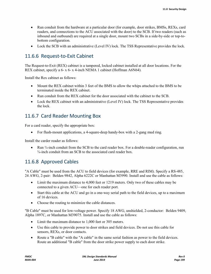
11.0 Security Design
FMOC SNL Design Standards Manual Rev 0MAN-004 June 2014 Page 199
Run conduit from the hardware at a particular door (for example, door strikes, BMSs, REXs, card readers, and connections to the ACU associated with the door) to the SCB. If two readers (such asinbound and outbound) are required at a single door, mount two SCBs in a side-by-side or top-to-bottom configuration.
Lock the SCB with an administrative (Level IV) lock. The TSS Representative provides the lock.
11.6.6 Request-to-Exit Cabinet
The Request-to-Exit (REX) cabinet is a tampered, locked cabinet installed at all door locations. For the REX cabinet, specify a 6- x 6- x 4-inch NEMA 1 cabinet (Hoffman A6N64).
Install the Rex cabinet as follows:
Mount the REX cabinet within 3 feet of the BMS to allow the whips attached to the BMS to be terminated inside the REX cabinet.
Run conduit from the REX cabinet for the door associated with the cabinet to the SCB.
Lock the REX cabinet with an administrative (Level IV) lock. The TSS Representative providesthe lock.
11.6.7 Card Reader Mounting Box
For a card reader, specify the appropriate box:
For flush-mount applications, a 4-square-deep handy-box with a 2-gang mud ring.
Install the carder reader as follows:
Run ¾-inch conduit from the SCB to the card reader box. For a double-reader configuration, run ¾-inch conduit from an SCB to the associated card reader box.
11.6.8 Approved Cables
"A Cable" must be used from the ACU to field devices (for example, RRE and RIM). Specify a RS-485, 24 AWG, 2-pair: Belden 9842, Alpha 6222C or Manhattan M3990. Install and use the cable as follows:
Limit the maximum distance to 4,000 feet or 1219 meters. Only two of these cables may be connected to a given ACUone for each reader port.
Start this cable at the ACU and go in a one-way serial path to the field devices, up to a maximum of 16 devices.
Choose the routing to minimize the cable distances.
"B Cable" must be used for low-voltage power. Specify 18 AWG, unshielded, 2-conductor: Belden 9409, Alpha 1897C, or Manhattan M39075. Install and use the cable as follows:
Limit the maximum distance to 1,000 feet or 305 meters.
Use this cable to provide power to door strikes and field devices. Do not use this cable for sensors, REXs, or door contacts.
Route a "B cable" with the "A cable" in the same serial fashion as power to the field devices.Route an additional "B cable" from the door strike power supply to each door strike.
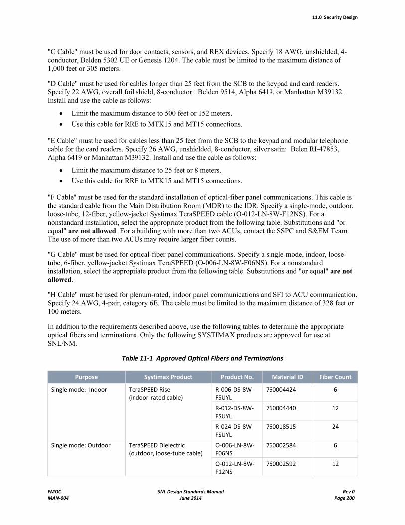
11.0 Security Design
FMOC SNL Design Standards Manual Rev 0MAN-004 June 2014 Page 200
"C Cable" must be used for door contacts, sensors, and REX devices. Specify 18 AWG, unshielded, 4-conductor, Belden 5302 UE or Genesis 1204. The cable must be limited to the maximum distance of 1,000 feet or 305 meters.
"D Cable" must be used for cables longer than 25 feet from the SCB to the keypad and card readers.Specify 22 AWG, overall foil shield, 8-conductor: Belden 9514, Alpha 6419, or Manhattan M39132.Install and use the cable as follows:
Limit the maximum distance to 500 feet or 152 meters.
Use this cable for RRE to MTK15 and MT15 connections.
"E Cable" must be used for cables less than 25 feet from the SCB to the keypad and modular telephone cable for the card readers. Specify 26 AWG, unshielded, 8-conductor, silver satin: Belen RI-47853, Alpha 6419 or Manhattan M39132. Install and use the cable as follows:
Limit the maximum distance to 25 feet or 8 meters.
Use this cable for RRE to MTK15 and MT15 connections.
"F Cable" must be used for the standard installation of optical-fiber panel communications. This cable is the standard cable from the Main Distribution Room (MDR) to the IDR. Specify a single-mode, outdoor, loose-tube, 12-fiber, yellow-jacket Systimax TeraSPEED cable (O-012-LN-8W-F12NS). For a nonstandard installation, select the appropriate product from the following table. Substitutions and "or equal" are not allowed. For a building with more than two ACUs, contact the SSPC and S&EM Team.The use of more than two ACUs may require larger fiber counts.
"G Cable" must be used for optical-fiber panel communications. Specify a single-mode, indoor, loose-tube, 6-fiber, yellow-jacket Systimax TeraSPEED (O-006-LN-8W-F06NS). For a nonstandard installation, select the appropriate product from the following table. Substitutions and "or equal" are not allowed.
"H Cable" must be used for plenum-rated, indoor panel communications and SFI to ACU communication.Specify 24 AWG, 4-pair, category 6E. The cable must be limited to the maximum distance of 328 feet or 100 meters.
In addition to the requirements described above, use the following tables to determine the appropriate optical fibers and terminations. Only the following SYSTIMAX products are approved for use at SNL/NM.
Table 11-1 Approved Optical Fibers and Terminations
Purpose Systimax Product Product No. Material ID Fiber Count
Single mode: Indoor TeraSPEED Rise (indoor-rated cable)
R-006-DS-8W-FSUYL
760004424 6
R-012-DS-8W-FSUYL
760004440 12
R-024-DS-8W-FSUYL
760018515 24
Single mode: Outdoor TeraSPEED Dielectric (outdoor, loose-tube cable)
O-006-LN-8W-F06NS
760002584 6
O-012-LN-8W-F12NS
760002592 12
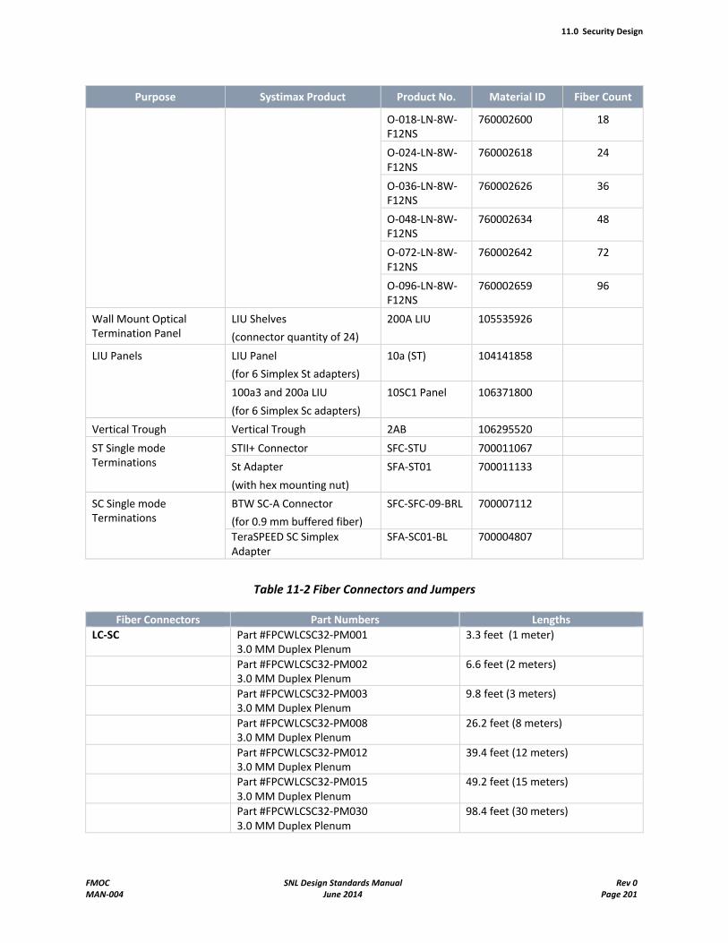
11.0 Security Design
FMOC SNL Design Standards Manual Rev 0MAN-004 June 2014 Page 201
Purpose Systimax Product Product No. Material ID Fiber Count
O-018-LN-8W-F12NS
760002600 18
O-024-LN-8W-F12NS
760002618 24
O-036-LN-8W-F12NS
760002626 36
O-048-LN-8W-F12NS
760002634 48
O-072-LN-8W-F12NS
760002642 72
O-096-LN-8W-F12NS
760002659 96
Wall Mount Optical Termination Panel
LIU Shelves
(connector quantity of 24)
200A LIU 105535926
LIU Panels LIU Panel
(for 6 Simplex St adapters)
10a (ST) 104141858
100a3 and 200a LIU
(for 6 Simplex Sc adapters)
10SC1 Panel 106371800
Vertical Trough Vertical Trough 2AB 106295520
ST Single mode Terminations
STII+ Connector SFC-STU 700011067
St Adapter
(with hex mounting nut)
SFA-ST01 700011133
SC Single mode Terminations
BTW SC-A Connector
(for 0.9 mm buffered fiber)
SFC-SFC-09-BRL 700007112
TeraSPEED SC Simplex Adapter
SFA-SC01-BL 700004807
Table 11-2 Fiber Connectors and Jumpers
Fiber Connectors Part Numbers Lengths
LC-SC Part #FPCWLCSC32-PM0013.0 MM Duplex Plenum
3.3 feet (1 meter)
Part #FPCWLCSC32-PM0023.0 MM Duplex Plenum
6.6 feet (2 meters)
Part #FPCWLCSC32-PM0033.0 MM Duplex Plenum
9.8 feet (3 meters)
Part #FPCWLCSC32-PM0083.0 MM Duplex Plenum
26.2 feet (8 meters)
Part #FPCWLCSC32-PM0123.0 MM Duplex Plenum
39.4 feet (12 meters)
Part #FPCWLCSC32-PM0153.0 MM Duplex Plenum
49.2 feet (15 meters)
Part #FPCWLCSC32-PM0303.0 MM Duplex Plenum
98.4 feet (30 meters)
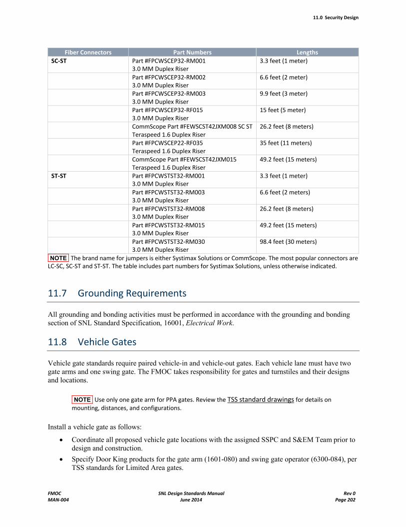
11.0 Security Design
FMOC SNL Design Standards Manual Rev 0MAN-004 June 2014 Page 202
Fiber Connectors Part Numbers Lengths
SC-ST Part #FPCWSCEP32-RM0013.0 MM Duplex Riser
3.3 feet (1 meter)
Part #FPCWSCEP32-RM0023.0 MM Duplex Riser
6.6 feet (2 meter)
Part #FPCWSCEP32-RM0033.0 MM Duplex Riser
9.9 feet (3 meter)
Part #FPCWSCEP32-RF0153.0 MM Duplex Riser
15 feet (5 meter)
CommScope Part #FEWSCST42JXM008 SC ST Teraspeed 1.6 Duplex Riser
26.2 feet (8 meters)
Part #FPCWSCEP22-RF035Teraspeed 1.6 Duplex Riser
35 feet (11 meters)
CommScope Part #FEWSCST42JXM015Teraspeed 1.6 Duplex Riser
49.2 feet (15 meters)
ST-ST Part #FPCWSTST32-RM0013.0 MM Duplex Riser
3.3 feet (1 meter)
Part #FPCWSTST32-RM0033.0 MM Duplex Riser
6.6 feet (2 meters)
Part #FPCWSTST32-RM0083.0 MM Duplex Riser
26.2 feet (8 meters)
Part #FPCWSTST32-RM0153.0 MM Duplex Riser
49.2 feet (15 meters)
Part #FPCWSTST32-RM0303.0 MM Duplex Riser
98.4 feet (30 meters)
NOTE The brand name for jumpers is either Systimax Solutions or CommScope. The most popular connectors are LC-SC, SC-ST and ST-ST. The table includes part numbers for Systimax Solutions, unless otherwise indicated.
11.7 Grounding Requirements
All grounding and bonding activities must be performed in accordance with the grounding and bonding section of SNL Standard Specification, 16001, Electrical Work.
11.8 Vehicle Gates
Vehicle gate standards require paired vehicle-in and vehicle-out gates. Each vehicle lane must have two gate arms and one swing gate. The FMOC takes responsibility for gates and turnstiles and their designsand locations.
NOTE Use only one gate arm for PPA gates. Review the TSS standard drawings for details on mounting, distances, and configurations.
Install a vehicle gate as follows:
Coordinate all proposed vehicle gate locations with the assigned SSPC and S&EM Team prior to design and construction.
Specify Door King products for the gate arm (1601-080) and swing gate operator (6300-084), per TSS standards for Limited Area gates.
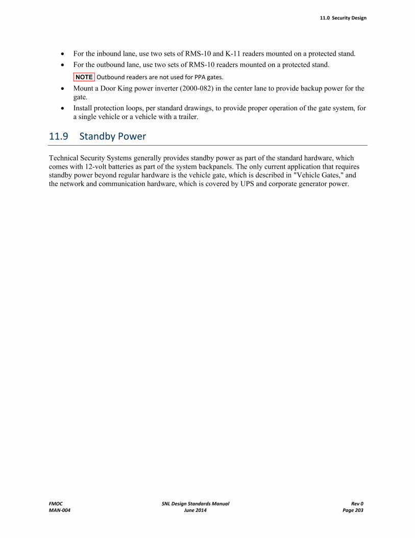
11.0 Security Design
FMOC SNL Design Standards Manual Rev 0MAN-004 June 2014 Page 203
For the inbound lane, use two sets of RMS-10 and K-11 readers mounted on a protected stand.
For the outbound lane, use two sets of RMS-10 readers mounted on a protected stand.
NOTE Outbound readers are not used for PPA gates.
Mount a Door King power inverter (2000-082) in the center lane to provide backup power for the gate.
Install protection loops, per standard drawings, to provide proper operation of the gate system, for a single vehicle or a vehicle with a trailer.
11.9 Standby Power
Technical Security Systems generally provides standby power as part of the standard hardware, which comes with 12-volt batteries as part of the system backpanels. The only current application that requires standby power beyond regular hardware is the vehicle gate, which is described in "Vehicle Gates," and the network and communication hardware, which is covered by UPS and corporate generator power.
Appendix A: Variances from Engineering Standards Program Requirements
Example: Building 969 Design/Build Project
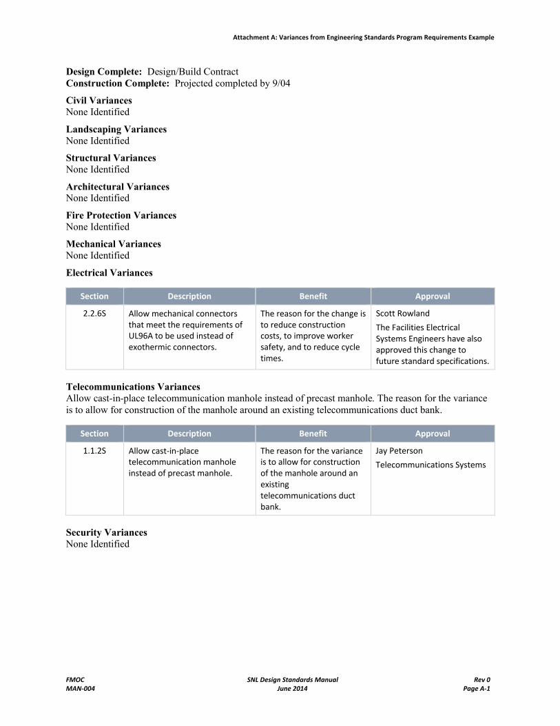
Attachment A: Variances from Engineering Standards Program Requirements Example
FMOC SNL Design Standards Manual Rev 0MAN-004 June 2014 Page A-1
Design Complete: Design/Build ContractConstruction Complete: Projected completed by 9/04
Civil VariancesNone Identified
Landscaping VariancesNone Identified
Structural VariancesNone Identified
Architectural VariancesNone Identified
Fire Protection VariancesNone Identified
Mechanical VariancesNone Identified
Electrical Variances
Section Description Benefit Approval
2.2.6S Allow mechanical connectors that meet the requirements of UL96A to be used instead of exothermic connectors.
The reason for the change is to reduce construction costs, to improve worker safety, and to reduce cycle times.
Scott Rowland
The Facilities Electrical Systems Engineers have also approved this change to future standard specifications.
Telecommunications VariancesAllow cast-in-place telecommunication manhole instead of precast manhole. The reason for the variance is to allow for construction of the manhole around an existing telecommunications duct bank.
Section Description Benefit Approval
1.1.2S Allow cast-in-place telecommunication manhole instead of precast manhole.
The reason for the variance is to allow for construction of the manhole around an existing telecommunications duct bank.
Jay Peterson
Telecommunications Systems
Security VariancesNone Identified

Appendix B: Electrical Equipment Labeling Designations
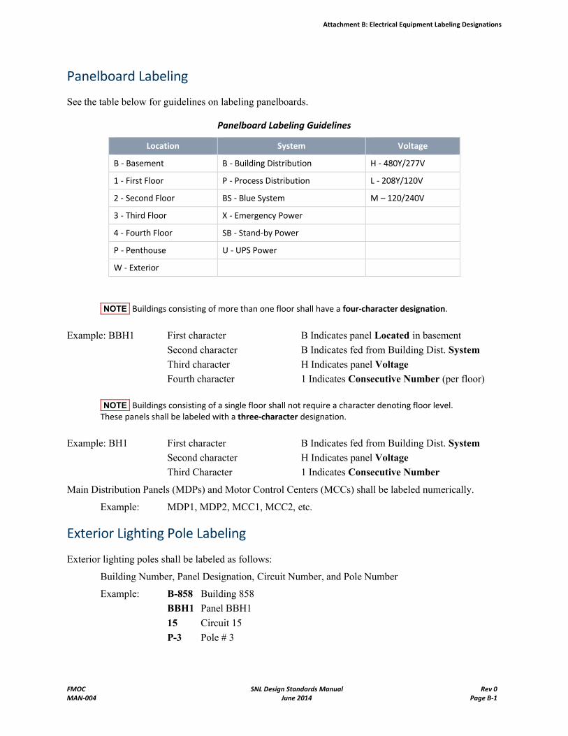
Attachment B: Electrical Equipment Labeling Designations
FMOC SNL Design Standards Manual Rev 0MAN-004 June 2014 Page B-1
Panelboard Labeling
See the table below for guidelines on labeling panelboards.
Panelboard Labeling Guidelines
Location System Voltage
B - Basement B - Building Distribution H - 480Y/277V
1 - First Floor P - Process Distribution L - 208Y/120V
2 - Second Floor BS - Blue System M – 120/240V
3 - Third Floor X - Emergency Power
4 - Fourth Floor SB - Stand-by Power
P - Penthouse U - UPS Power
W - Exterior
NOTE Buildings consisting of more than one floor shall have a four-character designation.
Example: BBH1 First character B Indicates panel Located in basement
Second character B Indicates fed from Building Dist. System
Third character H Indicates panel Voltage
Fourth character 1 Indicates Consecutive Number (per floor)
NOTE Buildings consisting of a single floor shall not require a character denoting floor level. These panels shall be labeled with a three-character designation.
Example: BH1 First character B Indicates fed from Building Dist. System
Second character H Indicates panel Voltage
Third Character 1 Indicates Consecutive Number
Main Distribution Panels (MDPs) and Motor Control Centers (MCCs) shall be labeled numerically.
Example: MDP1, MDP2, MCC1, MCC2, etc.
Exterior Lighting Pole Labeling
Exterior lighting poles shall be labeled as follows:
Building Number, Panel Designation, Circuit Number, and Pole Number
Example: B-858 Building 858
BBH1 Panel BBH1
15 Circuit 15
P-3 Pole # 3
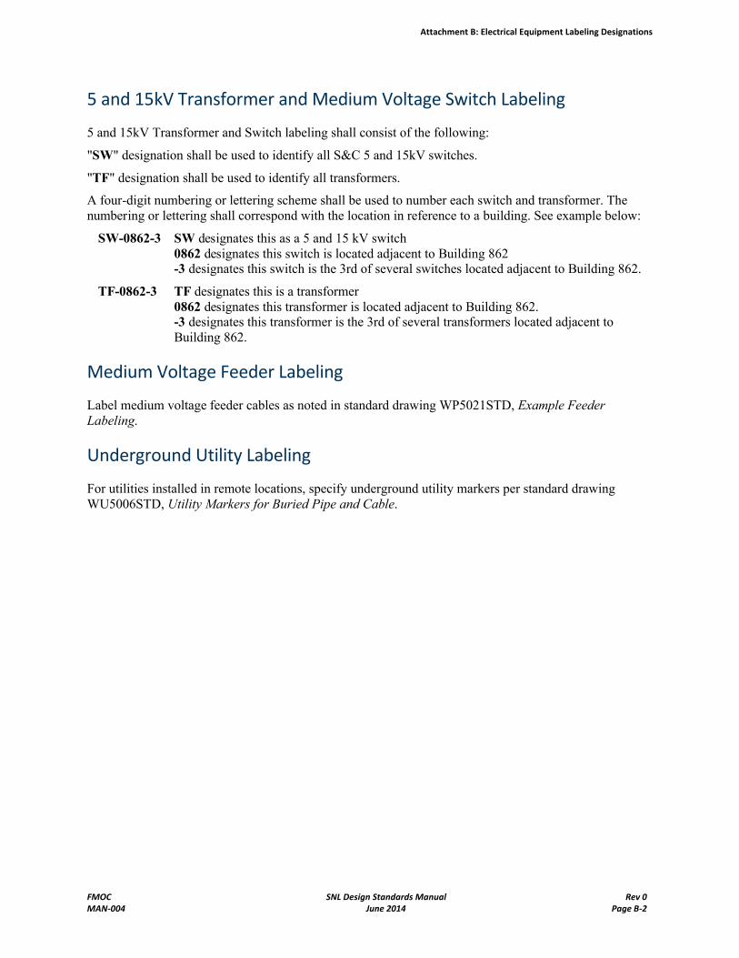
Attachment B: Electrical Equipment Labeling Designations
FMOC SNL Design Standards Manual Rev 0MAN-004 June 2014 Page B-2
5 and 15kV Transformer and Medium Voltage Switch Labeling
5 and 15kV Transformer and Switch labeling shall consist of the following:
"SW" designation shall be used to identify all S&C 5 and 15kV switches.
"TF" designation shall be used to identify all transformers.
A four-digit numbering or lettering scheme shall be used to number each switch and transformer. The numbering or lettering shall correspond with the location in reference to a building. See example below:
SW-0862-3 SW designates this as a 5 and 15 kV switch0862 designates this switch is located adjacent to Building 862-3 designates this switch is the 3rd of several switches located adjacent to Building 862.
TF-0862-3 TF designates this is a transformer0862 designates this transformer is located adjacent to Building 862.-3 designates this transformer is the 3rd of several transformers located adjacent to Building 862.
Medium Voltage Feeder Labeling
Label medium voltage feeder cables as noted in standard drawing WP5021STD, Example Feeder Labeling.
Underground Utility Labeling
For utilities installed in remote locations, specify underground utility markers per standard drawing WU5006STD, Utility Markers for Buried Pipe and Cable.