design tools for squeezing ground conditions in hard rock ...the magnitude of deformations that are...
TRANSCRIPT

Deep Mining 2017: Eighth International Conference on Deep and High Stress Mining – J Wesseloo (ed.) © 2017 Australian Centre for Geomechanics, Perth, ISBN 978-0-9924810-6-3
Deep Mining 2017, Perth, Australia 693
Design tools for squeezing ground conditions in hard rock mines
J Hadjigeorgiou University of Toronto, Canada
E Karampinos University of Toronto, Canada
Abstract Squeezing ground conditions are encountered in several underground rock mines. This paper addresses the selection of appropriate engineering tools that can be used for the prediction of squeezing and investigates the relative performance of different ground support options.
A clear distinction is made between squeezing as a result of weak rock or shear failure and structurally defined buckling failure of the rock mass. A critical assessment is made of available empirical tools with particular emphasis on their limitations.
The second part of the paper addresses issues with the use of numerical models and, in particular, the choice of numerical models that capture the prevalent mechanisms. A case study is presented whereby different reinforcement elements are used to control large deformations in mining drives. The paper provides a path forward to assessing the potential performance of new reinforcement elements at the same mine site.
Keywords: squeezing ground, ground support, empirical design, numerical modelling
1 Introduction Squeezing ground conditions refer to large convergence of excavations occurring during excavation and that may continue over time. These conditions are encountered in both tunnelling and in mining drives in poor quality or weak rock but also in structurally defined rock masses.
The choice and economics of ground support, however, is quite different between tunnelling and mining excavations. In tunnelling, where the tolerance for deformation is low, it is more easily justified to invest in ground support that can be more effective such as steel arches or ductile tunnel linings with yielding elements (Barla & Barla 2008; Schubert 2008), although they are more expensive. There are further options in the choice of excavation method and the use of ring liner support.
The magnitude of deformations that are acceptable for drifts can be high. Mining drives often remain in operation even after significant deformation has occurred, provided they can still allow the movement of mining equipment. In certain cases, the deformation can be in excess of 40% wall to wall strain (Karampinos et al. 2015b). An effective support strategy in hard rock mines should aim to control rather than arrest the deformation. A review of the support practices at mines operating under squeezing conditions in Australian and Canadian hard rock mines has been provided by Sandy et al. (2007), and Potvin and Hadjigeorgiou (2008). As mining operations progress deeper, squeezing becomes an increasing problem in underground hard rock mines. The large deformations resulting from these phenomena have significant repercussions in the ground support of the underground excavations. The implications often include the need of additional support and extensive rehabilitation work to keep the mine drives in operation.
A distinction is made between conditions where the rock mass deforms and fails in a uniform way, and in deep hard rock mines where squeezing is often controlled by structures and high stress. This results in non-uniform deformations and a buckling failure mechanism.
This paper investigates the available engineering tools that can be used for the assessment of the anticipated level of squeezing in hard rock mines and the design of ground support in such conditions. Emphasis is made
https://papers.acg.uwa.edu.au/p/1704_47_Hadjigeorgiou/
Design tools for squeezing ground conditions in hard rock mines J Hadjigeorgiou and E Karampinos
694 Deep Mining 2017, Perth, Australia
on the mechanics of the phenomena and the limitations of the available tools for different failure mechanisms. This includes empirical, analytical and numerical tools that can capture the squeezing mechanisms. The performance of different reinforcement strategies under squeezing conditions in hard rock mines is examined. A three-dimensional (3D) distinct element model that captures the squeezing mechanism at the LaRonde mine is used as an example to model explicitly reinforcement elements and examine the impact of different reinforcement strategies.
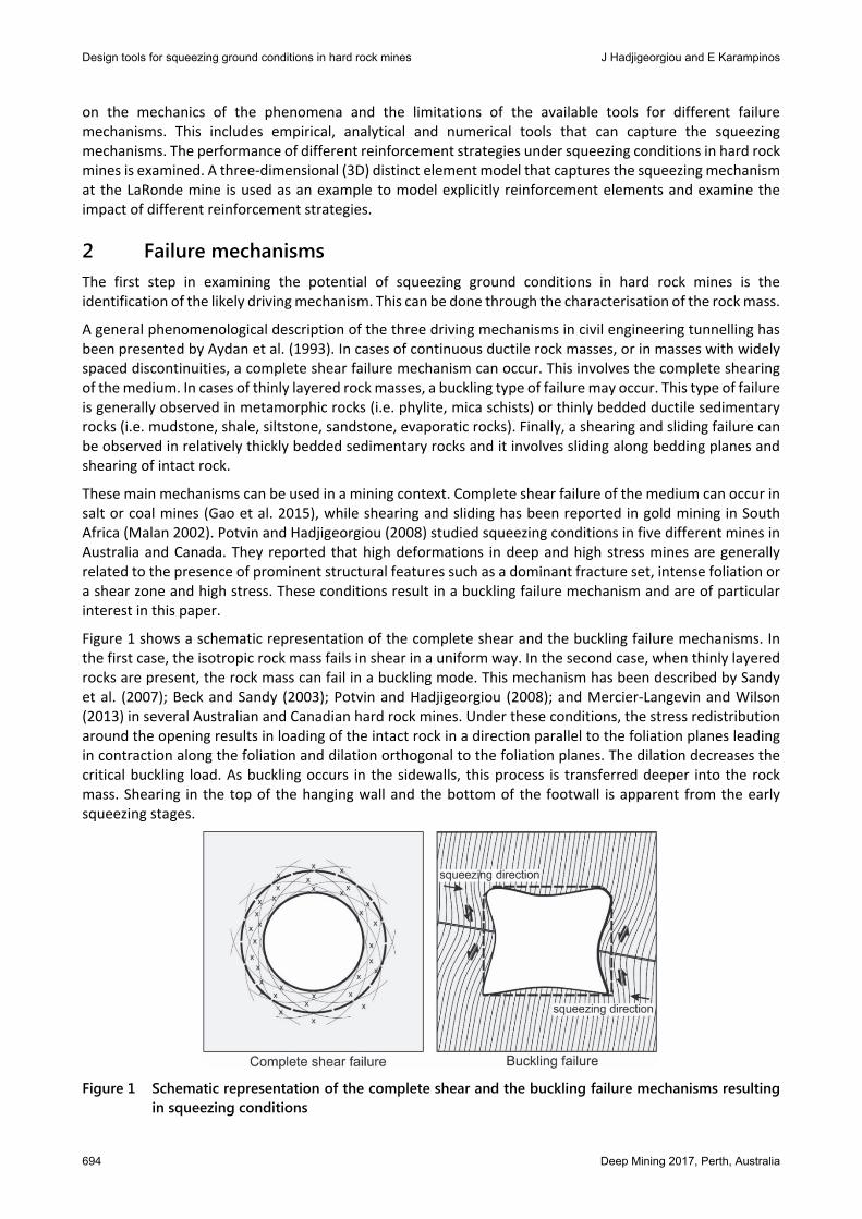
2 Failure mechanisms The first step in examining the potential of squeezing ground conditions in hard rock mines is the identification of the likely driving mechanism. This can be done through the characterisation of the rock mass.
A general phenomenological description of the three driving mechanisms in civil engineering tunnelling has been presented by Aydan et al. (1993). In cases of continuous ductile rock masses, or in masses with widely spaced discontinuities, a complete shear failure mechanism can occur. This involves the complete shearing of the medium. In cases of thinly layered rock masses, a buckling type of failure may occur. This type of failure is generally observed in metamorphic rocks (i.e. phylite, mica schists) or thinly bedded ductile sedimentary rocks (i.e. mudstone, shale, siltstone, sandstone, evaporatic rocks). Finally, a shearing and sliding failure can be observed in relatively thickly bedded sedimentary rocks and it involves sliding along bedding planes and shearing of intact rock.
These main mechanisms can be used in a mining context. Complete shear failure of the medium can occur in salt or coal mines (Gao et al. 2015), while shearing and sliding has been reported in gold mining in South Africa (Malan 2002). Potvin and Hadjigeorgiou (2008) studied squeezing conditions in five different mines in Australia and Canada. They reported that high deformations in deep and high stress mines are generally related to the presence of prominent structural features such as a dominant fracture set, intense foliation or a shear zone and high stress. These conditions result in a buckling failure mechanism and are of particular interest in this paper.
Figure 1 shows a schematic representation of the complete shear and the buckling failure mechanisms. In the first case, the isotropic rock mass fails in shear in a uniform way. In the second case, when thinly layered rocks are present, the rock mass can fail in a buckling mode. This mechanism has been described by Sandy et al. (2007); Beck and Sandy (2003); Potvin and Hadjigeorgiou (2008); and Mercier-Langevin and Wilson (2013) in several Australian and Canadian hard rock mines. Under these conditions, the stress redistribution around the opening results in loading of the intact rock in a direction parallel to the foliation planes leading in contraction along the foliation and dilation orthogonal to the foliation planes. The dilation decreases the critical buckling load. As buckling occurs in the sidewalls, this process is transferred deeper into the rock mass. Shearing in the top of the hanging wall and the bottom of the footwall is apparent from the early squeezing stages.
Figure 1 Schematic representation of the complete shear and the buckling failure mechanisms resulting
in squeezing conditions

Ground support
Deep Mining 2017, Perth, Australia 695
The squeezing conditions in hard rock mines can be studied through analytical, empirical or numerical methods. While the analytical methods are limited to ideal situations, empirical and numerical tools can provide essential information for the design of excavations in squeezing ground conditions.
3 Empirical guidelines Empirical guidelines or design tools aim to use past experience from other sites for preliminary assessment. These tools, however, should be used with caution. Their applicability is dependent on identifying the driving failure mechanism that is linked to the specific guidelines. Once a potential failure mechanism is identified, empirical tools can be used to assess the anticipated level of squeezing. The quality of predictions is restricted by the similarity of the ground conditions to cases in the database.
3.1 Shear failure mechanism Rock mass classification systems, such as RMR (Bieniawski 1989) and Q (Barton et al. 1974) are often used for zoning purposes identifying areas of weak rock. In this respect, they provide easy to use practical tools that are used for both civil and mining. A common limitation of most rock mass classification systems, however, is the assumption of an isotropic material behaviour. Of the two systems, Q makes specific reference to squeezing conditions which are treated as plastic flow of incompetent rock under high pressure and are accounted for in the Stress Reduction Factor (SRF) (Barton et al. 1974). It does not take into account the anisotropy and the orientation of the structures. There are several references on the use of the Q-system in tunnelling, including Singh et al. (1992) that suggested that squeezing in tunnels can occur when = 350 where H is the overburden in (m).
In a mining context, it should be remembered that in the constitutive database of the Q-system there were only limited case studies of tunnels reporting squeezing problems. Furthermore, civil engineering structures constitute the majority of case studies in the database. The RMR system has similar limitations, although it has been used as a design tool for determining the unsupported span for mining drives in weak rock (Sandbak and Rai 2013). There are no support guidelines directly derived from the RMR system for mining applications.
The selection of a support systems matching rock mass conditions relies on design charts such as that proposed by Grimstad and Barton (1993). The limitation of this approach for mining drives and for squeezing conditions have been discussed by Potvin and Hadjigeorgiou (2016). The RMR system is not directly linked to support recommendations and quite often there is a tendency to convert to the Q-system to make use of its support design charts. This conversion approach, however, is likely to introduce interpretation errors at the extreme conditions.
3.2 Buckling failure mechanism Once buckling is recognised as a potential failure mechanism due to the presence of thinly layered rock masses, the anticipated level of squeezing can be identified using empirical tools. The impact of structures should be taken into account.
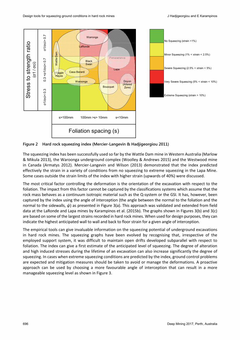
Mercier-Langevin and Hadjigeorgiou (2011) presented a ‘Hard Rock Squeezing Index’ for underground mines based on case studies from mining operations in Australia and Canada. This index can provide a first indication for the potential of squeezing and the long term strain level based on ranges for the foliation spacing and the stress to strength ratio as shown in Figure 2.
Design tools for squeezing ground conditions in hard rock mines J Hadjigeorgiou and E Karampinos
696 Deep Mining 2017, Perth, Australia
Figure 2 Hard rock squeezing index (Mercier-Langevin & Hadjigeorgiou 2011)
The squeezing index has been successfully used so far by the Wattle Dam mine in Western Australia (Marlow & Mikula 2013), the Waroonga underground complex (Woolley & Andrews 2015) and the Westwood mine in Canada (Armatys 2012). Mercier-Langevin and Wilson (2013) demonstrated that the index predicted effectively the strain in a variety of conditions from no squeezing to extreme squeezing in the Lapa Mine. Some cases outside the strain limits of the index with higher strain (upwards of 40%) were discussed.
The most critical factor controlling the deformation is the orientation of the excavation with respect to the foliation. The impact from this factor cannot be captured by the classifications systems which assume that the rock mass behaves as a continuum isotropic material such as the Q-system or the GSI. It has, however, been captured by the index using the angle of interception (the angle between the normal to the foliation and the normal to the sidewalls, ψ) as presented in Figure 3(a). This approach was validated and extended from field data at the LaRonde and Lapa mines by Karampinos et al. (2015b). The graphs shown in Figures 3(b) and 3(c) are based on some of the largest strains recorded in hard rock mines. When used for design purposes, they can indicate the highest anticipated wall to wall and back to floor strain for a given angle of interception.
The empirical tools can give invaluable information on the squeezing potential of underground excavations in hard rock mines. The squeezing graphs have been evolved by recognising that, irrespective of the employed support system, it was difficult to maintain open drifts developed subparallel with respect to foliation. The index can give a first estimate of the anticipated level of squeezing. The degree of alteration and high induced stresses during the lifetime of an excavation can also increase significantly the degree of squeezing. In cases when extreme squeezing conditions are predicted by the index, ground control problems are expected and mitigation measures should be taken to avoid or manage the deformations. A proactive approach can be used by choosing a more favourable angle of interception that can result in a more manageable squeezing level as shown in Figure 3.
No Squeezing (strain <1%)
Minor Squeezing (1% < strain < 2.5%)
Severe Squeezing (2.5% < strain < 5%)
Very Severe Squeezing (5% < strain < 10%)
Extreme Squeezing (strain > 10%)
100mm >s> 10mm s<10mm
Foliation spacing (s)
Stre
ss to
stre
ngth
ratio
(σ1
/ σci
)
σ1/σ
ci>
0.7
0.3
<σ1/σc
i< 0
.7σ1
/σci
< 0.
3
s>100mm
LaRonde
PerseveranceBlack Swan
Waroonga
Maggie Hayes
Lapa
Bousquet
Doyon (Altered Zone)
Wat
tle D
am
Casa Berardi
Warronga

Ground support
Deep Mining 2017, Perth, Australia 697
(a)
(b) (c)
Figure 3 Influence of the angle of interception on resulting strain: (a) squeezing index (Mercier-Langevin & Hadjigeorgiou 2011); (b) total wall-to-wall strain; and, (c) total back-to-floor strain
While changes in the orientation of development can be an effective strategy in mining under squeezing conditions, certain mining methods allow limited flexibility in such modifications. For cases when large deformations cannot be avoided, reactive mitigation measures can be adopted to control the excessive deformation. These measures are based on the use of an appropriate support strategy for the anticipated level of squeezing. Numerical modelling investigations can be used to examine different scenarios including the impact of different reinforcement strategies.
4 Analytical models
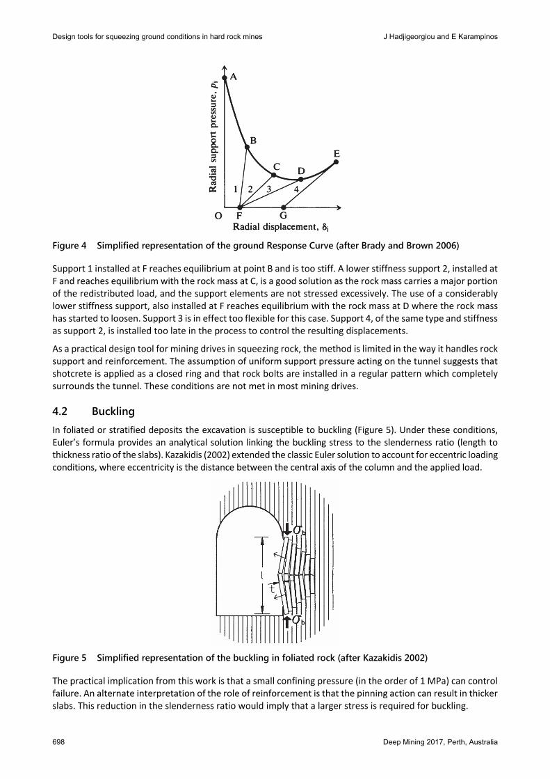
4.1 Ground reaction curves The Ground Reaction Curve or Ground Response method provides an excellent 2D tool to illustrate the rock support interaction in tunnels. The applicability of the method is limited to circular excavations in homogeneous isotropic rock masses. The method has been extended by Brown et al. (1983) to account for complex constitutive models. A simplified representation of the impact of the time and type of installation in controlling the time dependent deformations has been provided by Brady and Brown (2006) and is reproduced in Figure 4 where the required support line is given by ABCDE.
Design tools for squeezing ground conditions in hard rock mines J Hadjigeorgiou and E Karampinos
698 Deep Mining 2017, Perth, Australia
Figure 4 Simplified representation of the ground Response Curve (after Brady and Brown 2006)
Support 1 installed at F reaches equilibrium at point B and is too stiff. A lower stiffness support 2, installed at F and reaches equilibrium with the rock mass at C, is a good solution as the rock mass carries a major portion of the redistributed load, and the support elements are not stressed excessively. The use of a considerably lower stiffness support, also installed at F reaches equilibrium with the rock mass at D where the rock mass has started to loosen. Support 3 is in effect too flexible for this case. Support 4, of the same type and stiffness as support 2, is installed too late in the process to control the resulting displacements.
As a practical design tool for mining drives in squeezing rock, the method is limited in the way it handles rock support and reinforcement. The assumption of uniform support pressure acting on the tunnel suggests that shotcrete is applied as a closed ring and that rock bolts are installed in a regular pattern which completely surrounds the tunnel. These conditions are not met in most mining drives.
4.2 Buckling In foliated or stratified deposits the excavation is susceptible to buckling (Figure 5). Under these conditions, Euler’s formula provides an analytical solution linking the buckling stress to the slenderness ratio (length to thickness ratio of the slabs). Kazakidis (2002) extended the classic Euler solution to account for eccentric loading conditions, where eccentricity is the distance between the central axis of the column and the applied load.
Figure 5 Simplified representation of the buckling in foliated rock (after Kazakidis 2002)
The practical implication from this work is that a small confining pressure (in the order of 1 MPa) can control failure. An alternate interpretation of the role of reinforcement is that the pinning action can result in thicker slabs. This reduction in the slenderness ratio would imply that a larger stress is required for buckling.
Ground support
Deep Mining 2017, Perth, Australia 699
5 Numerical modelling Numerical modelling is a valuable tool for the simulation of the in situ rock mass behaviour under different conditions. Numerical methods can represent the rock mass either as a continuum or as a discontinuum medium. The choice of the appropriate modelling technique depends on the governing rock mass failure mechanism. In practice it is necessary to make several trade-offs between model complexity, sophistication, calibration requirements and running time.
5.1 Shear failure mechanism If the controlling mechanism is shear failure, the deformation of underground excavations can be simulated using finite element and finite difference methods. These methods can provide a relatively fast design assessment with an implicit or explicit representation of the role of fractures and can incorporate the impact of support.
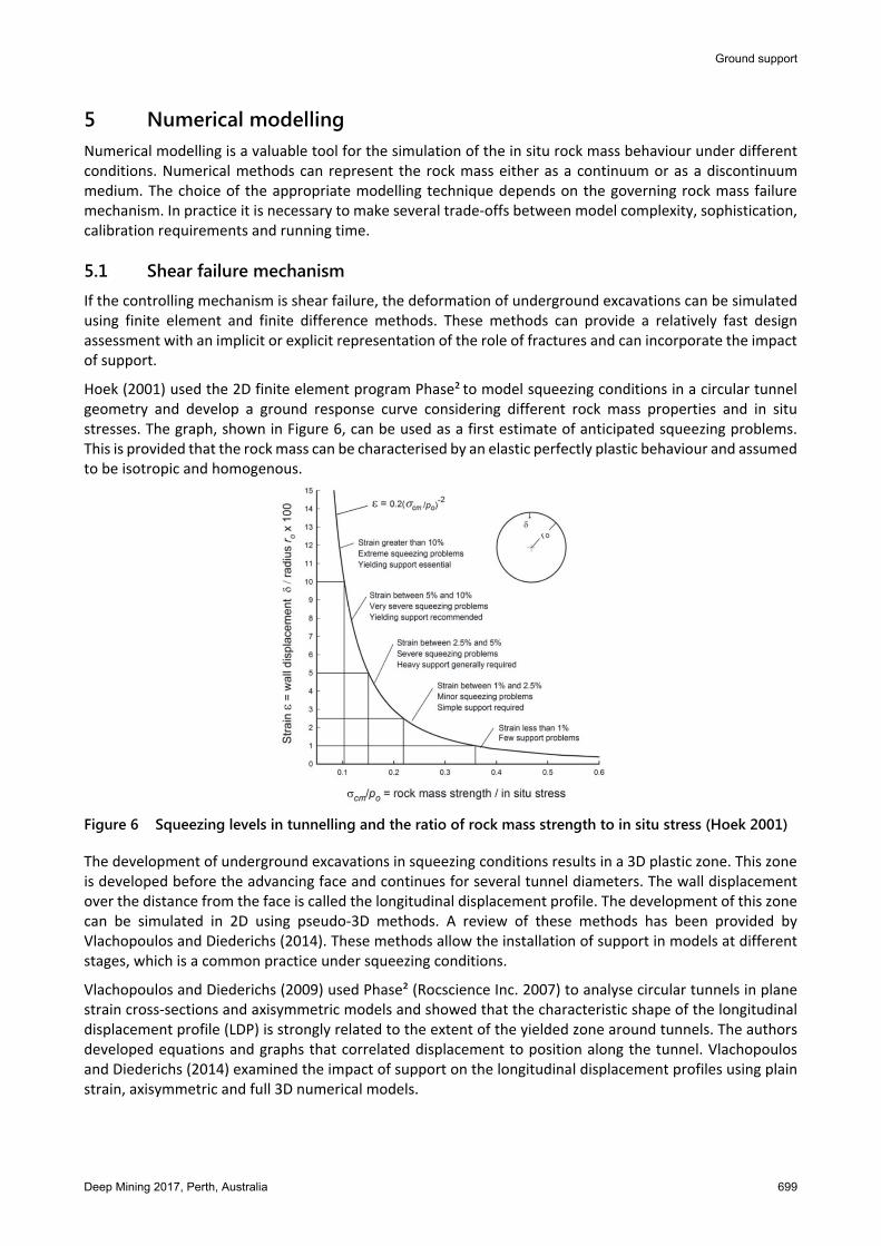
Hoek (2001) used the 2D finite element program Phase² to model squeezing conditions in a circular tunnel geometry and develop a ground response curve considering different rock mass properties and in situ stresses. The graph, shown in Figure 6, can be used as a first estimate of anticipated squeezing problems. This is provided that the rock mass can be characterised by an elastic perfectly plastic behaviour and assumed to be isotropic and homogenous.
Figure 6 Squeezing levels in tunnelling and the ratio of rock mass strength to in situ stress (Hoek 2001)
The development of underground excavations in squeezing conditions results in a 3D plastic zone. This zone is developed before the advancing face and continues for several tunnel diameters. The wall displacement over the distance from the face is called the longitudinal displacement profile. The development of this zone can be simulated in 2D using pseudo-3D methods. A review of these methods has been provided by Vlachopoulos and Diederichs (2014). These methods allow the installation of support in models at different stages, which is a common practice under squeezing conditions.
Vlachopoulos and Diederichs (2009) used Phase² (Rocscience Inc. 2007) to analyse circular tunnels in plane strain cross-sections and axisymmetric models and showed that the characteristic shape of the longitudinal displacement profile (LDP) is strongly related to the extent of the yielded zone around tunnels. The authors developed equations and graphs that correlated displacement to position along the tunnel. Vlachopoulos and Diederichs (2014) examined the impact of support on the longitudinal displacement profiles using plain strain, axisymmetric and full 3D numerical models.

Design tools for squeezing ground conditions in hard rock mines J Hadjigeorgiou and E Karampinos
700 Deep Mining 2017, Perth, Australia
The role of reinforcement and support using 3D continuum stress analysis models has been addressed by several authors in tunnelling, Perman et al. (2007); Vlachopoulos et al. (2013); Zhao et al. (2014). In a mining context, Vakili et al. (2013) used FLAC3D (Itasca Consulting Group Inc 2012) to investigate the impact of the time of installation of cable bolting and fibrecrete, as secondary support, on the effectiveness of a ground support system. These types of numerical experiments are useful to understand the interaction between different parameters. Beck et al. (2010) used a 3D finite element approach to capture the resulting deformations and the influence of reinforcement in a caving mine.
Continuum models cannot capture the observed squeezing mechanism driven by the presence of geological structures. An explicit representation of foliation in continuum finite difference and finite element models, following extensive calibration can result in an improved representation of the squeezing mechanism in hard rock mines. Continuum methods cannot reproduce the non-linear anisotropic behaviour of thinly layered rock masses to high stresses and excavations. They may simulate similar deformation levels to those measured in the field. They cannot, however, allow any block rotation or relative movement of blocks and cannot capture the buckling mechanism.
5.2 Buckling failure mechanism Continuum models, although used to model large deformations in underground mines, cannot capture the buckling mechanism. This is only possible by using discontinuum models that can explicitly simulate the rotation of rock blocks, the dilation of the fractures and the detachment of rock blocks from their initial positions. Karampinos et al. (2015a) used the 3D distinct element method (DEM) 3DEC version 5 (Itasca Consulting Group Inc 2013) to simulate the buckling mechanism at the LaRonde and Lapa mines in Canada (Figure 7). The extent of joint slip, and plastic zones around the opening indicated a direction of squeezing normal to the foliation planes. The numerical model showed slip of the foliation in the top of the hanging wall and the bottom of the footwall. This is consistent with field observations by Sandy et al. (2007), and Potvin and Hadjigeorgiou (2008). The dilation of the foliation planes in the sidewalls was simulated as well as the contraction in the back and the floor due to the stress redistribution.
Figure 7 Modelled squeezing conditions in LaRonde (Karampinos et al. 2015a)
Ground support
Deep Mining 2017, Perth, Australia 701
At the present time, the development of a 3D advancing face cannot be reproduced using a 3D model due to computational and time constraints. The progressive stress redistribution and displacement can be captured through a pseudo-3D approach. The progressive reduction of the forces acting at the boundaries of the excavation by a reduction factor (r) through a series of modelling steps overcame the limitations in modelling the development of the drift (Karampinos et al. 2015a). For r = 1 the face is considered to be ahead of the modelled section. As r reduces, the face approaches and overpasses the modelled section. At the last modelling step (r = 0) the face has no influence on the modelled section.
6 Ground support strategies
6.1 Design based on experience The selection of ground support systems for squeezing conditions in mining drives is more often than not, a reactive process. As the level of squeezing increases mines are forced to explore different alternatives that can mitigate the resulting deformations. Potvin and Hadjigeorgiou (2008) reviewed the support practices at mines operating under squeezing rock conditions from Australian and Canadian hard rock mines. A common thread is the introduction of yielding elements as part of the strategy. A difference in the two countries is the higher use of fibre reinforced shotcrete in Australian mines, with Canadian mines using mesh.
As the level of deformation increases shotcrete is too stiff and cracks. In these circumstances several mines opt to use mesh over shotcrete. At the same time, certain mines advocate the use of shotcrete overlain with mesh and covered by another layer of shotcrete. This is a very expensive option.
A strategy that appears to be successful is finding an optimal time of installation of secondary support. The merits of this approach are supported by the Ground Reaction Curve theory and can be visualised by numerical models. Practical benefits have been reported by Turcotte (2010) who reported a reduction of rehabilitation costs by the delayed use of hybrid bolts as secondary support.
6.2 Numerical modelling Several stress analysis packages allow for the introduction of reinforcement and support elements. This, however, adds a further degree of complexity into the models and results in longer execution times. As a model becomes more sophisticated then the calibration process is invariably longer. This is further compounded in the need for appropriate reinforcement and support elements to be used in the numerical models as well as having access to the necessary input data. The necessary tools, time commitment and level of expertise to undertake these tasks are not likely to be available at the mine site.
Section 6.2.1 provides a case study on the use of numerical models that capture the influence of different reinforcement options and time of installation at a mine experiencing structurally controlled squeezing. The case study is based on data and current ground support strategies at the LaRonde Mine. Section 6.2.2 is an example of forward modelling, whereby the calibrated models are used to predict the influence of using different reinforcement elements in the ground support system.
6.2.1 Modelling the role of reinforcement
The reinforcement strategy at LaRonde, for drifts developed subparallel to the foliation, is comprised of Ø22 mm, 1.9 m and 2.3 m long rebars for the back and Ø39 mm, 2 m long friction rock stabilisers (FRS) in the walls. Secondary reinforcement is installed in the sidewalls at 12 m behind the face comprised of 2 m long hybrid bolts. The hybrid bolt is a 1.9 m long (Ø22 mm) rebar installed in a 2 m long FRS (Ø39 mm). Its use as a secondary support strategy has been justified by reducing, significantly, the required rehabilitation under squeezing conditions (Turcotte 2010).
Karampinos et al. (2016) expanded on the 3D distinct element model that captured the buckling mechanism at LaRonde by introducing reinforcement elements. The performance of reinforcement was simulated explicitly using global reinforcement elements (Itasca Consulting Group Inc 2013). The mechanical properties

Design tools for squeezing ground conditions in hard rock mines J Hadjigeorgiou and E Karampinos
702 Deep Mining 2017, Perth, Australia
assigned to the global reinforcement elements were based on in situ pull tests and suppliers data. The elements take into account the plastic deformation in the rock mass in which the bonding between the rock bolts and the rock may fail in shear. Each element is divided into a number of segments with nodal points located at the end of each segment. Each node is associated with a finite difference zone for the calculation of the shear forces between the element and the zones. The axial stiffness is controlled by the cross-sectional area and the Young’s modulus of the bolt. The shear behaviour is simulated as a spring-slider system between the nodes.
The reinforcement was introduced to the model at different deformation stages to simulate the installation sequence used at LaRonde. Two cases were examined. In case 1, rebars were installed in the back and FRS in the sidewalls after the numerical equilibrium at stage r = 0.45. Hybrid bolts were subsequently installed after the numerical equilibrium at r = 0.2 and the reduction factor was reduced down to zero. The cable bolts were installed following secondary support and before the reduction factor was zero. The modelled displacement at the stage when each reinforcement was installed is shown in Figure 8.
Figure 8 Modelled displacement at the installation stage of each rock bolt for the examined cases (after
Karampinos et al. 2016)
6.2.2 Predictive modelling on the performance of new reinforcement elements
Following the calibration of the reinforcement models it is possible to explore different reinforcement options. In effect, the numerical models provide the means to investigate different options. This is particularly useful as new rock bolts become available. An example of this was an investigation into the use of the D-Bolt as a potential replacement of the hybrid bolt in the reinforcement sequence. A similar process was followed in the use of the D-bolt in the model as before, and the input properties were based on in situ pull test at LaRonde complemented by manufacturer’s data. D-Bolts were introduced to the model at r = 0.2 instead of hybrid bolts.
The performance of the reinforcement elements and the modelled displacement at the last modelling stage (r = 0) are shown in Figure 9. The plots show that, in both cases, the axial load in the back reached the yielding load (185 kN) but did not fail, while the bonds between the bolts and the blocks remained intact. The FRS in the sidewalls slipped under the excessive load in both cases. The hybrid bolts in case 1 slipped in a similar way as the FRS. However, they carried a higher axial load than the FRS, as expected. The D-Bolts in case 2, carried a higher axial load than the hybrid bolts. The D-Bolt was stretched between the anchor points. The anchor points remained intact while the part of the bolt between these points slipped.

Ground support
Deep Mining 2017, Perth, Australia 703
(a)
(b)
Figure 9 Impact of different reinforcement strategies on the modelled displacement using yielding bolts: (a) hybrid bolts in the sidewalls; and, (b) D-Bolts in the sidewalls
These numerical investigations demonstrated that the introduction of hybrid bolts in the support system had a significant impact on the overall displacement reducing the displacement by 18%. This was supported by the field data and observations. In the calibrated numerical model it was shown that the D-Bolt can carry higher loads than the hybrid bolt. Replacing the hybrid bolt by the D-Bolt, as secondary support, resulted in

Design tools for squeezing ground conditions in hard rock mines J Hadjigeorgiou and E Karampinos
704 Deep Mining 2017, Perth, Australia
more than 5% further reduction in displacement. If this trend is observed in the field this has significant implications on the use of the D-Bolt. This allows confidence in moving to the next stage in the introduction of new reinforcement elements, which is well defined field trials.
7 Conclusion This paper has provided an overview of the available tools in the analysis and design of mining drives under squeezing ground conditions. It has classified these tools based on their ability to simulate two distinct types of squeezing mechanisms. A further distinction was made based on tools capable of anticipating the expected level of squeezing in a mining drive and the ones that address their type of reinforcement and sequence of installation to best manage the anticipated large deformations.
Finally, a case study has been presented of the use of discontinuous 3D models that capture the performance of the reinforcement strategies at an underground hard rock mine. Of interest is the use of these calibrated models to investigate the behaviour of other reinforcement elements under the same ground conditions. This is a valuable tool in evaluating new reinforcement strategies and deciding on further field trials.
Acknowledgement The authors would like to acknowledge the financial support of Agnico Eagle Mines and the Natural Science and Engineering Research Council of Canada. The technical input of Pascal Turcotte, Marie-Michèle Drolet, Frederic Mercier-Langevin and Jim Hazard, at different stages of this work, is gratefully acknowledged.
References Armatys, M 2012, Modification des classifications géomécaniques pour les massifs rocheux schisteux, Mémoire de maîtris, École
Polytechnique de Montréal, Montreal. Aydan, Ö, Akagi, T & Kawamoto, T 1993, ‘The squeezing potential of rocks around tunnels; theory and prediction’, Rock Mechanics
and Rock Engineering, vol. 26, no. 12, pp. 137–163. Barla, GB & Barla, M 2008, ‘Innovative tunnelling construction methods in squeezing rock’, in P Boca (ed.), What Future for the
Infrastructure? Innovation & Sustainable Development, Patron Editore, Bologna, pp. 103–119. Barton, N, Lien, R & Lunde, J 1974, ‘Engineering classification of rock masses for the design of tunnel support’, Rock Mechanics and
Rock Engineering, vol. 6, no. 4, pp. 189–236. Beck, D, Kassbohm, S & Putzar, G 2010, ‘Multi-scale simulation of ground support designs for extreme tunnel closure’, in Y Potvin
(ed.), Proceedings of the Second International Symposium on Block and Sublevel Caving, Australian Centre for Geomechanics, Perth, pp. 146–160.
Beck, DA & Sandy, MP 2003, ‘Mine sequencing for high recovery in Western Australian mines’, in MD Kuruppu & PA Lilly (eds), Proceedings of the 12th International Symposium on Mine Planning and Equipment Selection, The Australasian Institution of Mining and Metallurgy, Carlton South, pp. 38–46.
Bieniawski, ZT 1989, ‘Engineering Rock Mass Classifications’, John Wiley & Sons, New York, pp. 251. Brady, B & Brown, E 2006, ‘Rock Mechanics for underground mining’, 3rd edn, Springer. Brown, E, Bray, J, Ladanyi, B & Hoek, E 1983, ‘Characteristic line calculations for rock tunnels’, Journal of Geotechnical Engineering
Division, American Society of Civil Engineers, vol. 109, pp. 15–39. Gao, F, Stead, D & Kang, H 2015, ‘Numerical simulation of squeezing failure in a coal mine roadway due to mining-induced stresses’,
Rock Mechanics and Rock Engineering, vol. 48, no. 4, pp. 1635–1645. Grimstad, E & Barton, N 1993, ‘Updating of the Q-system for NMT’, Proceedings of International Symposium on Sprayed
Concrete-Modern Use of Wet Mix Sprayed Concrete for Underground Support, 18–21 October, Fagernes, Oslo, Norwegian Concrete Association.
Hoek, E 2001, ‘Big tunnels in bad rock’, Journal of Geotechnical and Geoenvironmental Engineering, vol. 127, no. 9, pp. 726–740. Itasca Consulting Group Inc 2012, FLAC3D — Fast Lagrangian Analysis of Continua, software, version 5.0, Itasca Consulting Group Inc,
Minnesota. Itasca Consulting Group Inc 2013, 3DEC − Theory and Background, Itasca Consulting Group Inc, Minnesota. Karampinos, E, Hadjigeorgiou, J, Hazzard, J & Turcotte, P 2015a, ‘Discrete element modelling of the buckling phenomenon in deep
hard rock mines’, International Journal of Rock Mechanics and Mining Sciences, vol. 80, pp. 346–356. Karampinos, E, Hadjigeorgiou, J & Turcotte, P 2016. ‘Discrete element modelling of the influence of reinforcement in structurally
controlled squeezing mechanisms in a hard rock mine’, Rock Mechanics and Rock Engineering. Karampinos, E, Hadjigeorgiou, J, Turcotte, P & Mercier-Langevin, F 2015b, ‘Large-scale deformation in underground hard-rock mines’,
Journal of the Southern African Institute of Mining and Metallurgy, vol. 115, no. 7, pp. 645–652.
Ground support
Deep Mining 2017, Perth, Australia 705
Kazakidis, VN 2002, ‘Confinement effects and energy balance analyses for buckling failure under eccentric loading conditions’, Rock Mechanics and Rock Engineering, vol. 35, no. 2, pp. 115–126.
Malan, D 2002, ‘Manuel Rocha medal recipient simulating the time-dependent behaviour of excavations in hard rock’, Rock Mechanics and Rock Engineering, vol. 35, no. 4, pp. 225–254.
Marlow, P & Mikula, PA 2013, ‘Shotcrete ribs and cemented rock fill ground control methods for stoping in weak squeezing rock at Wattle Dam Gold Mine’, in B Brady & Y Potvin (eds), Proceedings of the Seventh International Symposium on Ground Support in Mining and Underground Construction, Australian Centre for Geomechanics, Perth pp. 133–148.
Mercier-Langevin, F & Hadjigeorgiou, J 2011, ‘Towards a better understanding of squeezing potential in hard rock mines’, Mining Technology, vol. 120, no. 1, pp. 36–44.
Mercier-Langevin, F & Wilson, D 2013, ‘Lapa mine – ground control practices in extreme squeezing ground’, in B Brady & Y Potvin (eds.), Proceedings of the Seventh International Symposium on Ground Support in Mining and Underground Construction, Australian Centre for Geomechanics, Perth, pp. 119–132.
Perman, F, Sjoberg, J, Olofsson, O & Rosengren, L 2007, ‘Numerical analyses of shotcrete reinforcement’, Proceedings of the 11th Congress of the International Society for Rock Mechanics, International Society for Rock Mechancis, Lisboa.
Potvin, Y & Hadjigeorgiou, J 2008, ‘Ground support strategies to control large deformations in mining excavations’, Journal of the South African Institute of Mining & Metallurgy, vol. 108, no. 7, pp. 397–404.
Potvin, Y & Hadjigeorgiou, J 2016, 'Selection of Ground Support for Mining Drives based on the Q-System', in E Nordlund, TH Jones & A Eitzenberger (eds), Proceedings of the Eighth International Symposium on Ground Support in Mining and Underground Construction, 12–14 September 2016, Luleå, Sweden, Luleå University of Technology, Luleå, pp. 16.
Rocscience Inc. 2007, PHASE2, 2D finite element software, Rocscience Inc., Toronto, www.rocscience.com Sandbak, L & Rai, A 2013, ‘Ground support strategies at the turquoise ridge joint venture, Nevada’, Rock Mechanics and Rock
Engineering, vol. 46, no. 3, pp. 437–454. Sandy, MP, Gibson, W & Gaudreau, D 2007, ‘Canadian and Australian ground support practices in high deformation environments’,
in Y Potvin, J Hadjigeorgiou & D Stacey (eds), Challenges in Deep and High Stress Mining, Australian Centre for Geomechanics, Australian Centre for Geomechanics, Perth, pp. 297–311.
Schubert, W 2008, ‘Design of ductile tunnel linings’, Proceedings of the 42nd US Rock Mechanics Symposium, American Rock Mechanics Association, Alexandria, paper ARMA 08-146.
Singh, B, Jethwa, JL, Dube, AK & Singh, B 1992, ‘Correlation between observed support pressure and rock mass quality’, Tunnelling and Underground Space Technology, vol. 7, no. 1, pp. 59–74.
Turcotte, P 2010, ‘Field behaviour of hybrid bolt at LaRonde Mine’, in M Van Sint Jan & Y Potvin (eds.), Proceedings of the Fifth International Seminar on Deep and High Stress Mining, Australian Centre for Geomechanics, Perth, pp. 309–319.
Vakili, A, Sandy, M, Mathews, M & Rodda, B 2013, ‘Ground support design under highly stresses conditions’, in B Brady & Y Potvin (eds.), Proceedings of the Seventh International Symposium on Ground Support in Mining and Underground Construction, Australian Centre for Geomechanics, Perth, pp. 551–564.
Vlachopoulos, N & Diederichs, M 2009, ‘Improved longitudinal displacement profiles for convergence confinement analysis of deep tunnels’, Rock Mechanics and Rock Engineering, vol. 42, no. 2, pp. 131–146.
Vlachopoulos, N, Diederichs, M, Marinos, V & Marinos, P 2013, ‘Tunnel behaviour associated with the weak Alpine rock masses of the Driskos Twin Tunnel system, Egnatia Odos Highway’, Canadian Geotechnical Journal, vol. 50, no. 1, pp. 91–120.
Vlachopoulos, N & Diederichs, M 2014, ‘Appropriate uses and practical limitations of 2D numerical analysis of tunnels and tunnel support response’, Geotechnical and Geological Engineering, vol. 32, no. 2, pp. 469–488.
Woolley, C & Andrews, P 2015, ‘Short-term solutions to squeezing ground at Agnew Gold Mine, Western Australia’, in Y Potvin (ed.), Proceedings of the International Seminar on Underground Design Methods 2015, Australian Centre for Geomechanics, Perth, pp. 199–214.
Zhao, K, Janutolo, M, Barla, G & Chen, G 2014, ‘3D simulation of TBM excavation in brittle rock associated with fault zones: The Brenner Exploratory Tunnel case’, Engineering Geology, vol. 181, pp. 93–111.

Design tools for squeezing ground conditions in hard rock mines J Hadjigeorgiou and E Karampinos
706 Deep Mining 2017, Perth, Australia