design validation through testing of a double-tube...
TRANSCRIPT
399 International Journal of Control Theory and Applications
Design Validation through Testing of a Double-tube Counter-flowheat Exchanger
Design Validation through Testing of a Double-tube Counter-flowheatExchanger
Oruganti Yaga Dutta, T. Therisa and B. Nageswara Rao*
Departmentof MechanicalEngineering, K LUniversity, Green Fields, Vaddeswaram, Guntur-522502, IndiaE-mails: [email protected]; [email protected]
Abstract: To examine the validity of empirical relations for design, a comparative study is made considering the testdata of a double-tube counter-flow heat exchanger. The outlet temperatures of the cold and hot fluids in the heatexchangerhave beenevaluated directly by adoptingeffectivenessmethod.The overall heat transfer coefficientis evaluatedconsidering the dimensions and material properties of tubes, properties of hot and cold fluids, inlet temperatures,mass-flow rates and the fouling factors.The estimates of outlet temperatures are matching well with measured ones.This study confirms the validation of empirical relations for use in the design as well as in the performance evaluationof double-tube counter-flow heat exchangers in service.Keywords: Double-tube counter-flow heat exchanger; effectiveness; friction factor; inlet and outlet temperatures;massflow rate; Nusselt number; overall heat transfer coefficient;Prandtl number; Reynolds number.
1. INTRODUCTION
Heat exchangers are classified according to transfer process, construction, flow arrangement (viz.,parallel flow,counter flow, single-pass cross flow and multi-pass cross flow.), surface compactness, number of fluids and heattransfer mechanisms [1]. They have been developed for use in the steam power plants, chemical processingplants, heating and air conditioning in buildings, household refrigerators, car radiators, radiators for space vehiclesand so on. The design of heat exchangers involves cost, size, weight and economic considerations [2]. In steamand chemical power plants, cost of heat exchanger is the main concern, whereas, the size and weight are thedominant factors in radiators. High efficiency gasket plate heat exchangers (PHE) are also being used in freecooling, cooling tower isolation, water heaters, waste heat recovery, heat pump isolation and thermal (ice) storagesystems. These are cost effective, simple and compact in size, which can be cleaned easily and no extra spacerequirement for dismantling.The heat exchanger life assessment system has been developed to estimate theultrasonic immersion length for conversion to the corrosion depth inside cooling water/air fin type tubes [3].Heat exchangers are of expendable type having limited life, which are usually designed for 10 years. Fouling isthe most common problem that is very difficult to identify. It is preferred to have the maximum flow rate withincreased turbulence within the channel to retard the rate of fouling. It is well known fact that the actual designof heat exchangers is involved when compared to the heat transfer analysis alone due to cost, weight, size and
International Journal of Control Theory and Applications 400
Oruganti Yaga Dutta, T. Therisa and B. Nageswara Rao
economic considerations [4].Experiments have been performed by several researchers and examined the performanceof heat exchangers utilizing various empirical relations for friction factor and Nusselt number [5-8].
The computational fluid dynamics (CFD) codes in use are FLUENT, CFX, STAR CD, FIDAP, ADINA,CFD2000 and PHOENICS [9]. Compared to the correlation based methods, the use of CFD in heat exchangerdesign is limited due to the requirement of large amounts of computer power, computer memory and computationaltime [10-12]. The CFD developmental activities are progressing rapidly to become an integral part of all designprocesses. However, there is a need for comparison of CFD simulations with experimental data due to lack ofuniversally applicable boundary conditions and turbulent models [13-16] and design validation through testingis unavoidable.
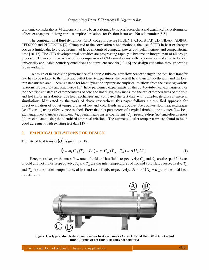
To design or to assess the performance of a double-tube counter-flow heat exchanger, the total heat transferrate has to be related to the inlet and outlet fluid temperatures, the overall heat transfer coefficient, and the heattransfer surface area. There is a need for identifying the appropriate empirical relations from the existing variousrelations. Potrascioiu and Radulescu [17] have performed experiments on the double-tube heat exchangers. Forthe specified constant inlet temperatures of cold and hot fluids, they measured the outlet temperatures of the coldand hot fluids in a double-tube heat exchanger and compared the test data with complex iterative numericalsimulations. Motivated by the work of above researchers, this paper follows a simplified approach fordirect evaluation of outlet temperatures of hot and cold fluids in a double-tube counter-flow heat exchanger(see Figure 1) using effectivenessmethod. From the inlet parameters of a typical double-tube counter-flow heatexchanger, heat transfer coefficient (h), overall heat transfer coefficient (Um), pressure drop (�P) and effectiveness(�) are evaluated using the identified empirical relations. The estimated outlet temperatures are found to be ingood agreement with existing test data [17].
2. EMPIRICAL RELATIONS FOR DESIGN
The rate of heat transfer � �Q� is given by [18],
ln)()( TUATTCmTTCmQ mtcicopcchohiphh ������� (1)
Here, mc and mh are the mass flow rates of cold and hot fluids respectively; Cpc and Cph are the specific heatsof cold and hot fluids respectively; Thi and Tci are the inlet temperatures of hot and cold fluids respectively; Tho
and Tco are the outlet temperatures of hot and cold fluids respectively; )( oot dDLA �� � , is the total heat
transfer area.
Figure 1: A typical double-tube counter-flow heat exchanger (A) Inlet of cold fluid; (B) Outlet of hotfluid; (C)Inlet of hot fluid; (D) Outlet of cold fluid
401 International Journal of Control Theory and Applications
Design Validation through Testing of a Double-tube Counter-flowheat Exchanger
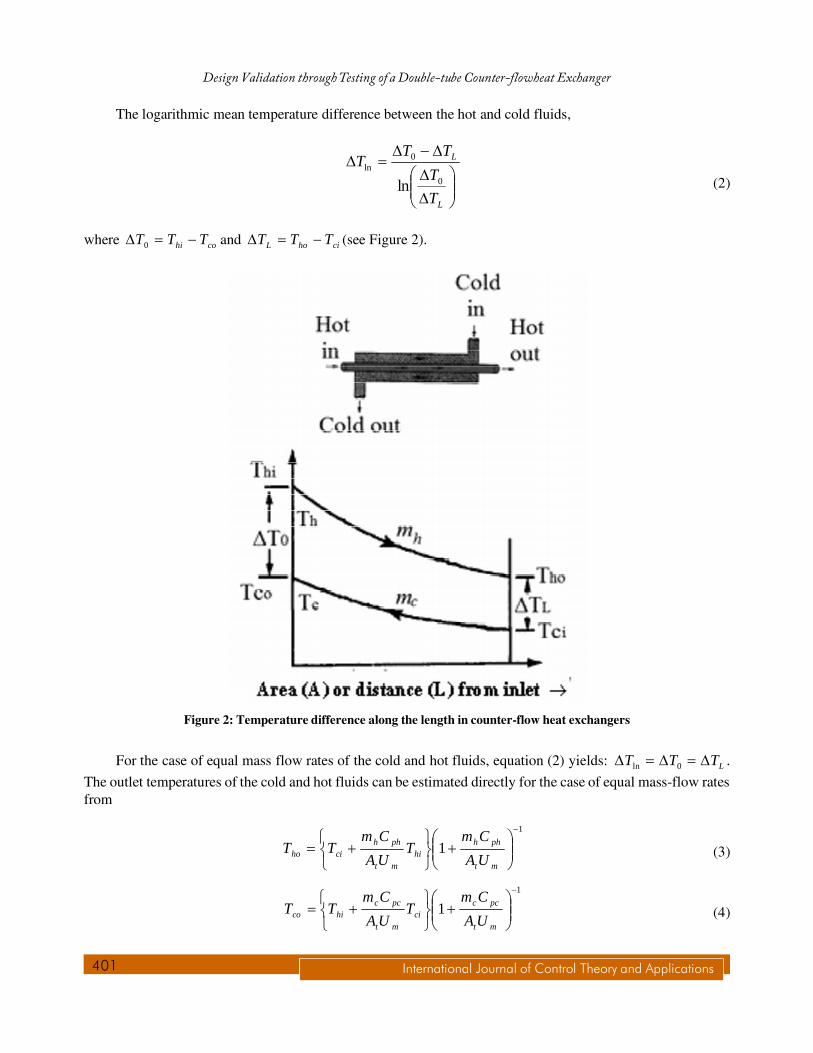
The logarithmic mean temperature difference between the hot and cold fluids,
���
����
������
��
L
L
T
T
TTT
0
0ln
ln (2)
where cohi TTT ��� 0 and cihoL TTT ��� (see Figure 2).
Figure 2: Temperature difference along the length in counter-flow heat exchangers
For the case of equal mass flow rates of the cold and hot fluids, equation (2) yields: LTTT ����� 0ln .
The outlet temperatures of the cold and hot fluids can be estimated directly for the case of equal mass-flow ratesfrom
1
1�
���
����
��
���
���
��mt
phhhi
mt
phhciho UA
CmT
UA
CmTT (3)
1
1�
���
����
��
���
���
��mt
pccci
mt
pcchico UA
CmT
UA
CmTT (4)
International Journal of Control Theory and Applications 402
Oruganti Yaga Dutta, T. Therisa and B. Nageswara Rao
The overall heat transfer coefficient (Um) can be obtained from
ofo
i
oo
i
fio
ii
o
m hR
d
dd
d
Rd
hd
d
U
1ln
2
1����
�
����
����
� , (5)
in which di and do are the inner and outer diameters of the inner tube respectively; WKmR fi /000172.0 2� and
WKmR fo /000352.0 2� are the fouling resistances corresponding to inner and outer tubes; KmW ../52�� is
the thermal conductivity of the tube material (AISI 316 Stainless steel) [19]; i
fhi d
Nuh
�� and
e
fco D
Nuh
��
are the heat transfer coefficients for hot and cold fluids respectively. The equivalent diameter, o
oie d
dDD
22 �� .
Di is the inner diameter of the outer tube. The Nusselt numbers hNu and cNu corresponding to the hot and cold
fluids are obtained from
� �1Pr3037.122
PrRe
���
f
fNu (6)
Defining the average velocity,ch
hmh A
mu
��
� and the cross-sectional area, 2
4 ic dA�
� , the Reynolds number
for hot side fluid, i
himh
d
mdu
���� �4
Re �� . Similarly, definingthe hydraulic diameter, oih dDD �� , average
velocity, cc
cmc A
mu
��
� and the cross-sectional area, � �22
4 oic dDA ���
, the Reynolds number for cold side
fluid, �� hmc Du
�Re . The friction factor (f), for hot and cold fluids:Re
16�f for Re<2000 and
� � 23Reln56.1 ���f for Re>2000. The Prandtl number (Pr) is at film temperature.
In order to simplify the complex iterative evaluation procedure for the outlet temperatures of the cold and
hot fluids, the effectiveness � �� is defined as the ratio of actual heat transfer rate � �Q� to the maximum possible
heat transfer rate � �maxQ� , which can be written as [20-24]
� �� � � �
� �� � � �cihip
cicopcc
cihip
hohiphh
TTmC
TTCm
TTmC
TTCm
Q
Q
�
��
�
���
minminmax�
�� (7)
From equation (7), one can write
403 International Journal of Control Theory and Applications
Design Validation through Testing of a Double-tube Counter-flowheat Exchanger
� �� �cihi
phh
p
hiho TTCm
mCTT ��� min� (8)
� �� �cihi
pcc
p
cico TTCm
mCTT ��� min� (9)
Here (mCp)min is the smaller of mhCph and mcCpc for the hot and cold fluids.
Using equations (8) and (9), one can find
� �� �cihi
pcc
pTT
Cm
mCT �
���
�
���
���� min
0 1�
(10)
� �� �cihi
phh
p
L TTCm
mCT �
���
�
���
���� min1�
(11)
From Ref. [18], it is noted that � �mtL UMA
T
T��
��
exp0
(12)
Using equations (10) and (11) in equation (12), one gets the effectiveness,
��
���
��
��� �
�
���
phh
mt
pcCp
mt
Cm
UMA
CmmC
UMA
)exp(1)(
)exp(1
min
� ;
phhpcc CmCmM
11�� (13)
The effectiveness � �� in equation (13) is defined in terms of the parameters tA , mU , phhCm and pccCm ,
which can be found easily for the specified inlet temperatures of the hot and cold fluids. Later on, the outlettemperature of the hot and cold fluids can be determined directly using equations (8) and (9).
The pressure drop � �hP� and � �cP� in hot and cold fluid tubes are evaluated from [19]
24
2mh
hpi
h
uN
d
LfP
��� (14)
24
2mc
hph
c
uN
D
LfP
��� (15)
L is the length of the heat exchanger (m) and the number of hair pins, hpN =1. It should be noted
that the friction factor (f) should be evaluated corresponding to the Reynolds number (Re) of hot and cold sidefluids.

International Journal of Control Theory and Applications 404
Oruganti Yaga Dutta, T. Therisa and B. Nageswara Rao
3. ANALYSIS
A double-tube heat exchanger (see Figure 1) consists of a tube placed concentrically inside another tube of alarger diameter with appropriate fittings to direct the flow of one fluid through inner tube, and the other throughthe annular space. The double-tube heat exchangers are being used for sensible heating or cooling of processfluids in small heat transfer areas. Potrascioiu and Radulescu [17] have performed experiments on the double-tube heat exchangers for the specified constant inlet temperatures of cold and hot fluids and measured the outlettemperatures of the cold and hot fluids. They have compared the experimental data with their numerical simulationsand claimed that their model can be used for designing industrial double-tube heat exchangers in the refineries.Their mathematical model contains an equation of the heat balance associated to hot and cold fluids, mass-flow
rates, inlet and unknown outlet temperatures. They also equated the rate of heat transfer � �Q� with the product of
the overall heat transfer coefficient � �mU , total heat transfer area � �tA and the Logarithmic Mean Temperature
Difference � �lnT� . They have obtained two equations for the unknown outlet temperatures of the cold and hot
fluids which are non-linear in nature and solved them through an iterative process.Two case studies have beenmade and compared their numerical simulations with the measured outlet temperatures of cold and hot fluids. Incase-I, tests are conducted maintaining constant inlet temperatures of cold fluid and varying inlet temperaturesof the hot fluid. In case-II, tests are conducted maintaining constant inlet temperatures of the hot fluid andvarying inlet temperatures of the cold fluid.
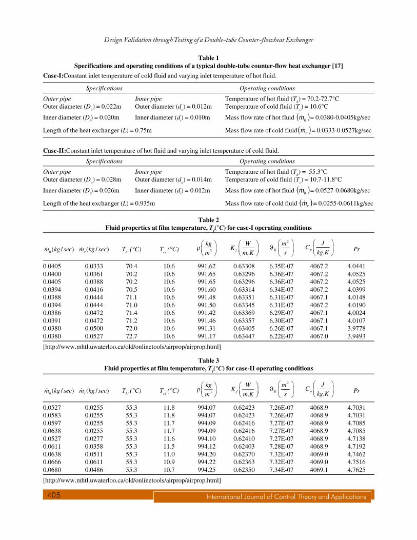
The heat exchanger has four ports, two for inlet and two for outlet of the hot and cold fluids. For thespecifications andoperating conditions of a typical double-tube counter-flow heat exchanger in Table 1, the fluid
properties at film temperature ��
���
� ��
2hici
f
TTT are generated for hot and cold fluids and presented in Tables 2
and 3. From the geometrical and fluid properties, mass flow rate and inlet temperature of hot and cold fluids, one
can find the maximum possible heat transfer rate � �maxQ� , the Reynolds number (Re), and the Prandtl number
(Pr). The friction factor (f) corresponding to the Reynolds number, Re (Re < 2000 for laminar flow regime,whereas for the turbulent flow regime, Re> 2000) is evaluated. Estimating the heat transfer coefficientshi and
hofor hot and cold fluids, the overall heat transfer coefficient is calculated from equation (5). The effectiveness � �� is
found from equation (13). The outlet temperature of the hot and cold fluids is estimated from equations (8) and(9).
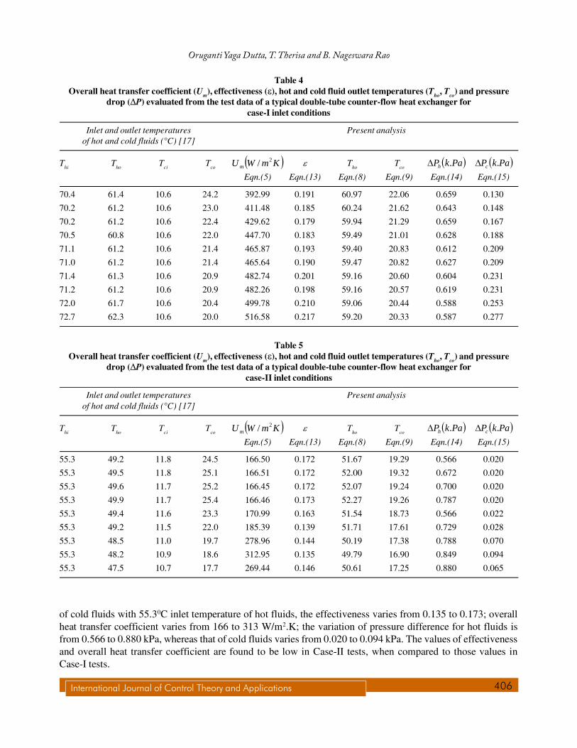
Tables 4 and 5give the measured inlet and outlet temperatures of hot and cold fluids, estimated outlet
temperatures, overall heat transfer coefficients � �mU , effectiveness � �� and pressure drop � �P� . The present
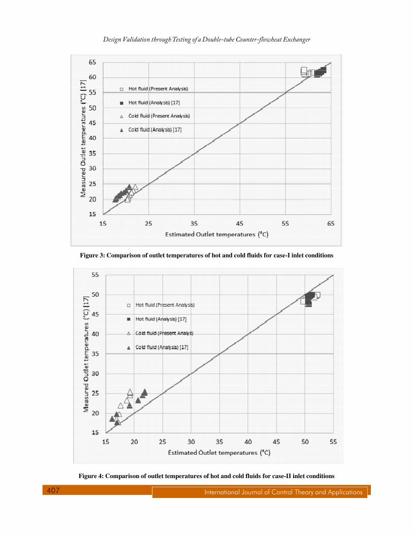
analysis results (in Tables 4 and 5) show a good comparison of measured and estimated outlet temperatures ofthe hot and cold fluids.Figures 3 and 4 show the comparison of measured and estimated outlet temperatures ofthe cold and hot fluids. Regarding the variation of temperatures of hot and cold fluids in the counter-flow heatexchangers (in which the hot and cold fluids enter from opposite ends as in Figure-2), the inlet temperature of thehot fluid (Thi) is higher than the inlet temperature of the cold fluid (Tci), whereas the outlet temperature of the coldfluid (Tco) increases and that of the hot fluid (Tho) decreases for both case-I and Case-II tests [see Tables 4 and 5].The present analysis results are found to be close to the test resultsof the outlet temperature of hot and cold fluids[17], when compared to those of Ref. [17] from the complex iterative numerical simulations.In Case-I tests forthe specified mass flow rates and the range of inlet temperature of hot fluids with 10.60C inlet temperature ofcold fluids, the effectiveness varies from 0.179 to 0.217; overall heat transfer coefficient varies from393 to 517W/m2.K; the variation of pressure difference for hot fluids is from 0.587 to 0.659 kPa, whereas that of cold fluidsvaries from 0.188 to 0.277 kPa.In Case-II tests for the specified mass flow rates and the range of inlet temperature
405 International Journal of Control Theory and Applications
Design Validation through Testing of a Double-tube Counter-flowheat Exchanger
Table 1Specifications and operating conditions of a typical double-tube counter-flow heat exchanger [17]
Case-I:Constant inlet temperature of cold fluid and varying inlet temperature of hot fluid.
Specifications Operating conditions
Outer pipe Inner pipe Temperature of hot fluid (Th) = 70.2-72.7°COuter diameter (Do) = 0.022m Outer diameter (do) = 0.012m Temperature of cold fluid (Tc) = 10.6°C
Inner diameter (Di) = 0.020m Inner diameter (di) = 0.010m Mass flow rate of hot fluid � �hm� = 0.0380-0.0405kg/sec
Length of the heat exchanger (L) = 0.75m Mass flow rate of cold fluid � �cm� = 0.0333-0.0527kg/sec
Case-II:Constant inlet temperature of hot fluid and varying inlet temperature of cold fluid.
Specifications Operating conditions
Outer pipe Inner pipe Temperature of hot fluid (Th) = 55.3°COuter diameter (Do) = 0.028m Outer diameter (do) = 0.014m Temperature of cold fluid (Tc) = 10.7-11.8°C
Inner diameter (Di) = 0.026m Inner diameter (di) = 0.012m Mass flow rate of hot fluid � �hm� = 0.0527-0.0680kg/sec
Length of the heat exchanger (L) = 0.935m Mass flow rate of cold fluid � �cm� = 0.0255-0.0611kg/sec
Table 2Fluid properties at film temperature, Tf(°C) for case-I operating conditions
( / )hm kg sec� ( / )cm kg sec� Thi (°C) Tci (°C) 3
kg
m� ��� �� � ,f
WK
m K� �� �� �
2
K
m
s
� �� � �
� � .p
JC
kg K
� �� �� �
Pr
0.0405 0.0333 70.4 10.6 991.62 0.63308 6.35E-07 4067.2 4.04410.0400 0.0361 70.2 10.6 991.65 0.63296 6.36E-07 4067.2 4.05250.0405 0.0388 70.2 10.6 991.65 0.63296 6.36E-07 4067.2 4.05250.0394 0.0416 70.5 10.6 991.60 0.63314 6.34E-07 4067.2 4.03990.0388 0.0444 71.1 10.6 991.48 0.63351 6.31E-07 4067.1 4.01480.0394 0.0444 71.0 10.6 991.50 0.63345 6.31E-07 4067.2 4.01900.0386 0.0472 71.4 10.6 991.42 0.63369 6.29E-07 4067.1 4.00240.0391 0.0472 71.2 10.6 991.46 0.63357 6.30E-07 4067.1 4.01070.0380 0.0500 72.0 10.6 991.31 0.63405 6.26E-07 4067.1 3.97780.0380 0.0527 72.7 10.6 991.17 0.63447 6.22E-07 4067.0 3.9493
[http://www.mhtl.uwaterloo.ca/old/onlinetools/airprop/airprop.html]
Table 3Fluid properties at film temperature, Tf(°C) for case-II operating conditions
( / )hm kg sec� ( / )cm kg sec� Thi (°C) Tci (°C) 3
kg
m� ��� �� � .f
WK
m K� �� �� �
2
K
m
s
� �� � �
� � .p
JC
kg K
� �� �� �
Pr
0.0527 0.0255 55.3 11.8 994.07 0.62423 7.26E-07 4068.9 4.70310.0583 0.0255 55.3 11.8 994.07 0.62423 7.26E-07 4068.9 4.70310.0597 0.0255 55.3 11.7 994.09 0.62416 7.27E-07 4068.9 4.70850.0638 0.0255 55.3 11.7 994.09 0.62416 7.27E-07 4068.9 4.70850.0527 0.0277 55.3 11.6 994.10 0.62410 7.27E-07 4068.9 4.71380.0611 0.0358 55.3 11.5 994.12 0.62403 7.28E-07 4068.9 4.71920.0638 0.0511 55.3 11.0 994.20 0.62370 7.32E-07 4069.0 4.74620.0666 0.0611 55.3 10.9 994.22 0.62363 7.32E-07 4069.0 4.75160.0680 0.0486 55.3 10.7 994.25 0.62350 7.34E-07 4069.1 4.7625
[http://www.mhtl.uwaterloo.ca/old/onlinetools/airprop/airprop.html]
International Journal of Control Theory and Applications 406
Oruganti Yaga Dutta, T. Therisa and B. Nageswara Rao
Table 4Overall heat transfer coefficient (Um), effectiveness ( ), hot and cold fluid outlet temperatures (Tho, Tco) and pressure
drop ( P) evaluated from the test data of a typical double-tube counter-flow heat exchanger forcase-I inlet conditions
Inlet and outlet temperatures Present analysisof hot and cold fluids (°C) [17]
Thi Tho Tci Tco � �KmWU m2/ � Tho Tco
� �PakPh .� � �PakPc .�Eqn.(5) Eqn.(13) Eqn.(8) Eqn.(9) Eqn.(14) Eqn.(15)
70.4 61.4 10.6 24.2 392.99 0.191 60.97 22.06 0.659 0.130
70.2 61.2 10.6 23.0 411.48 0.185 60.24 21.62 0.643 0.148
70.2 61.2 10.6 22.4 429.62 0.179 59.94 21.29 0.659 0.167
70.5 60.8 10.6 22.0 447.70 0.183 59.49 21.01 0.628 0.188
71.1 61.2 10.6 21.4 465.87 0.193 59.40 20.83 0.612 0.209
71.0 61.2 10.6 21.4 465.64 0.190 59.47 20.82 0.627 0.209
71.4 61.3 10.6 20.9 482.74 0.201 59.16 20.60 0.604 0.231
71.2 61.2 10.6 20.9 482.26 0.198 59.16 20.57 0.619 0.231
72.0 61.7 10.6 20.4 499.78 0.210 59.06 20.44 0.588 0.253
72.7 62.3 10.6 20.0 516.58 0.217 59.20 20.33 0.587 0.277
Table 5Overall heat transfer coefficient (Um), effectiveness ( ), hot and cold fluid outlet temperatures (Tho, Tco) and pressure
drop ( P) evaluated from the test data of a typical double-tube counter-flow heat exchanger forcase-II inlet conditions
Inlet and outlet temperatures Present analysisof hot and cold fluids (°C) [17]
Thi Tho Tci Tco � �KmWU m2/ � Tho Tco
� �PakPh .� � �PakPc .�Eqn.(5) Eqn.(13) Eqn.(8) Eqn.(9) Eqn.(14) Eqn.(15)
55.3 49.2 11.8 24.5 166.50 0.172 51.67 19.29 0.566 0.020
55.3 49.5 11.8 25.1 166.51 0.172 52.00 19.32 0.672 0.020
55.3 49.6 11.7 25.2 166.45 0.172 52.07 19.24 0.700 0.020
55.3 49.9 11.7 25.4 166.46 0.173 52.27 19.26 0.787 0.020
55.3 49.4 11.6 23.3 170.99 0.163 51.54 18.73 0.566 0.022
55.3 49.2 11.5 22.0 185.39 0.139 51.71 17.61 0.729 0.028
55.3 48.5 11.0 19.7 278.96 0.144 50.19 17.38 0.788 0.070
55.3 48.2 10.9 18.6 312.95 0.135 49.79 16.90 0.849 0.094
55.3 47.5 10.7 17.7 269.44 0.146 50.61 17.25 0.880 0.065
of cold fluids with 55.30C inlet temperature of hot fluids, the effectiveness varies from 0.135 to 0.173; overallheat transfer coefficient varies from 166 to 313 W/m2.K; the variation of pressure difference for hot fluids isfrom 0.566 to 0.880 kPa, whereas that of cold fluids varies from 0.020 to 0.094 kPa. The values of effectivenessand overall heat transfer coefficient are found to be low in Case-II tests, when compared to those values inCase-I tests.
407 International Journal of Control Theory and Applications
Design Validation through Testing of a Double-tube Counter-flowheat Exchanger
Figure 3: Comparison of outlet temperatures of hot and cold fluids for case-I inlet conditions
Figure 4: Comparison of outlet temperatures of hot and cold fluids for case-II inlet conditions
International Journal of Control Theory and Applications 408
Oruganti Yaga Dutta, T. Therisa and B. Nageswara Rao
4. CONCLUDING REMARKS
Appropriate empirical relations are identified for assessing the efficacy of the double-tube counter-flow heatexchanger through comparison of test data. Effectiveness method is used for direct evaluation of the outlettemperatures of the hot and cold fluids in the heat exchanger. The empirical relations are useful in the design aswell as in the performance evaluation of double-tube counter-flow heat exchangers in service.Future work is
directed towards the selection of optimum input parameters such as mass flow rates of hot and cold fluids � �ch mm , ;
inlet temperatures of hot and cold fluids � �cihi TT , to achieve maximum heat transfer rate � �Q� and minimum
pressure drop � �P� by adopting the Taguchi method [25-27] and performing minimum number of experiments.
REFERENCES
[1] R. K. Shah, “Heat Exchangers”, in Encyclopedia of Energy Technology and the Environment, edited by A. Bisio and S. G.Boots, pp. 1651-1670, John Wiley & Sons, New York, 1994.
[2] N. H. Afgan and E. U. Schlunder, “Heat Exchangers: Design and Theory”, McGraw-Hill Book Company, New York,1974.
[3] T. Friebel, M. Stockmann and R. Haber,”Heat exchanger fouling detection and lifetime estimation by regression”, Proceedingsof the Second Int. Conf. on Intelligent Control Systems and Signal Processing, Istanbul, Turkey (2009).
[4] M.Necati Ozisik, “Basic Heat Transfer”, McGraw-Hill, Inc. (1997).
[5] D. Chisholm andA. S.Wanniarachchi, “Mal-distribution in single-pass mixed-channel plate heat exchangers”, in CompactHeat Exchangers for Power and Process Industries, HTD-Vol. 201, ASME, New York, 1992.
[6] A. C. Talik, L.S. Fletcher, N.K. Anand and L. W. Swanson, “Heat transfer and pressure drop characteristics of a plate heatexchanger using a propylene-glycol/water mixture as the working fluid”, Proceedings of30th National. Heat TransferConference, Vol. 12, HTD- Vol. 314, ASME New York, 1995.
[7] A. Muley andR. M.Manglik, “Experimental investigation of heat transfer enhancement in a PHE with â=60° chevronplates”, in Heat and Mass Transfer, Tata McGraw-Hill, New Delhi, India (1995), p. 737.
[8] H. Martin, “A theoretical approach to predict the performance of chevron type plate heat exchangers”, Chem. Eng. Prog.,Vol. 35, pp. 301-310 (1996).
[9] E. Ozden, I. Tari, “Shell side CFD analysis of a small shell-and-tube heat exchanger”, Energy Conversion & Management,Vol. 51, pp. 1004-1014 (2010).
[10] S. Jain, A. Joshi, P. K. Bansal, “A new approach to numerical simulation of small sized plate heat exchangers with chevronplates”, Journal of Heat Transfer, vol. 129, pp. 291-297 (2007).
[11] B. Sunden, “Computational heat transfer in heat exchangers”, Heat Transfer Engineering, vol.28, pp. 895–897 (2007)
[12] B. Sunden, “Computational fluid dynamics in research and design of heat exchangers”, Heat Transfer Engineering, vol.28,pp. 898–910 (2007)
[13] X.H. Han, L.Q. Cui, S.J. Chen, G. M. Chen and Q. Wang, “A numerical and experimental study of chevron, corrugated-plate heat exchangers”, Communications in Heat &Mass Transfer, vol. 37, pp.1008-1014 (2010).
[14] M. M. Aslam Bhutta, N. Hayat,M. H. Bashir, A. R. Khan, K. N. Ahmad and S. Khan, “CFD applications in various heatexchangers design: A review”, Applied Thermal Engineering, vol.32, pp. 1-12 (2012).
[15] I. A. Stogiannis, S. V. Paras, O. P. Arsenyeva and P. O. Kapustenko, “CFD modelling of hydrodynamics and heat transferin Channels of a PHE”,Chemical Engineering Transactions, vol.35 (2013).
[16] Jan Skocilasand Ievgen Palaziuk, “CFD simulation of the heat transfer process in a chevron plate heat exchanger using theSST turbulence model”,Acta Polytechnica, vol.55, No.4, pp. 267–274 (2015)
[17] C. Patrascioiu and S. Radulescu, Modeling and simulation of the doubletube heatexchanger case studies. In: Advances inFluid Mechanics, Heat and Mass Transfer, pp 35–41 (2012).
409 International Journal of Control Theory and Applications
Design Validation through Testing of a Double-tube Counter-flowheat Exchanger
[18] M.Necati Ozisik, “Basic Heat Transfer”, McGraw-Hill, Inc. (1997).
[19] S. Kakac, H. Liu and A. Pramuanjaorenkj, “Heat Exchangers: Selection, Rating and Thermal Design”, Third Edition, CRCPress, FL, USA (2012).
[20] B. Sahin, Y. Ust, I. Teke and H.H. Erdem, “Performance analysis and optimization of heat exchangers: a new thermoeconomicapproach”, Appl Therm Eng, Vol.30, pp.104-109 (2010).
[21] Rafal Laskowski, “The black box model of a double-tube counter-flow heat exchanger”, Heat Mass Transfer, Vol.51,pp.1111-1119 (2015).
[22] R.K. Shah and D.P. Sekulic, “Fundamentals of Heat Exchanger Design”, John Wiley & Sons, New York (2003).
[23] Y.A. Cengel, “Heat and Mass Transfer”, McGraw-Hill, New York (2007).
[24] F.P. Incropera, D.P. Dewitt, T.L. Bergman, and A.S. Lavine, “Principles of Heat and Mass Transfer”, Seventh Edition,Wiley India Pvt. Ltd., New Delhi, India (2015).
[25] J. Singaravelu, D. Jeya kumar and B. Nageswara Rao, “Taguchi’s approach for reliability and safety assessments of stageseparation process of a multistage launch vehicle”, Reliability Engineering and Safety, vol.94, pp.1526-1541 (2009).
[26] J. Singaravelu, D. Jeya kumar and B. Nageswara Rao, “Rigid body separation dynamics on large strapon boosters ofmultistage launch vehicles”, In: Advances in Engineering Research, volume 1 (Editor: Victoria M. Petrova), pp.153-193,Nova Science Publishers, Inc. (2011).
[27] J. Singaravelu, D. Jeya kumar and B. Nageswara Rao, “Reliability and safety assessments of the satellite separation processof a typical launch vehicle”, Journal of Defense Modeling and Simulation: Applications, Methodology, Technology, vol.9,No. 4, pp. 369-382 (2011).