designation:c1063-11b designation: c1063 - 12a2).pdfthis document is not an astm standard and is...
TRANSCRIPT

This document is not an ASTM standard and is intended only to provide the user of an ASTM standard an indication of what changes have been made to the previous version. Because it may not be technically possible to adequately depict all changes accurately, ASTM recommends that users consult prior editions as appropriate. In all cases only the current version of the standard as published by ASTM is to be considered the official document.
Designation:C1063-11b Designation: C1063 - 12a
Standard Specification for Installation of Lathing and Furring to Receive Interior and Exterior Portland Cement-Based Plaster
1
This standard is issued under the fixed designation C1063; the number immediately following the designation indicates the year of
original adoption or, in the case of revision, the year of last revision. A number in parentheses indicates the year of last reapproval. A
superscript epsilon (´) indicates an editorial change since the last revision or reapproval.
This standard has been approved for use by agencies of the Department of Defense.
1. Scope*
1.1 This specification covers the minimum requirements for lathing and furring for the application of exterior and interior portland cement-based plaster as in Specification C926 or Specification C841.
1.2 Where a fire resistance rating is required for plastered assemblies and constructions, details of construction shall be i n
accordance with reports of fire tests of assemblies that have met the requirements of the fire rating imposed.
1.3 Where a specific degree of sound control is required for plastered assemblies and constructions, details of construction shall be
in accordance with official reports of tests conducted in recognized testing laboratories in accordance with the applicable
requirements of Test Method E90. 1.4 The values stated in inch-pound units are to be regarded as standard. The values given in parentheses are mathematical
conversions to SI units that are provided for information only and are not considered standard.
2. Referenced Documents
2.1 ASTM Standards:2
A641/A641M Specification for ZincCoated (Galvanized) Carbon Steel Wire
A653/A653M Specification for Steel Sheet, Zinc-Coated (Galvanized) or Zinc-Iron Alloy-Coated (Galvannealed) by the
Hot-Dip Process B69 Specification for Rolled Zinc
B221 Specification for Aluminum and Aluminum-Alloy Extruded Bars, Rods, Wire, Profiles, and Tubes
C11 Terminology Relating to Gypsum and Related Building Materials and Systems C841 Specification for Installation of Interior Lathing and Furring C847 Specification for Metal Lath
C926 Specification for Application of Portland Cement-Based Plaster
C933 Specification for Welded Wire Lath
C954 Specification for Steel Drill Screws for the Application of Gypsum Panel Products or Metal Plaster Bases to Steel Studs
from 0.033 in. (0.84 mm) to 0.112 in. (2.84 mm) in Thickness
C1002 Specification for Steel Self-Piercing Tapping Screws for the Application of Gypsum Panel Products or Metal Plaster
Bases to Wood Studs or Steel Studs C1032 Specification for Woven Wire Plaster Base D1784 Specification for Rigid Poly(Vinyl Chloride) (PVC) Compounds and Chlorinated Poly(Vinyl Chloride) (CPVC)
Compounds
D4216 Specification for Rigid Poly(Vinyl Chloride) (PVC) and Related PVC and Chlorinated Poly(Vinyl Chloride) (CPVC) Building Products Compounds
E90 Test Method for Laboratory Measurement of Airborne Sound Transmission Loss of Building Partitions and Elements
3. Terminology
3.1 Definitions—For definitions relating to Ceilings and Walls, see Terminology C11. 3.2 Definitions of Terms Specific to This Standard:
1 This specification is under the jurisdiction of ASTM Committee C11 on Gypsum and Related Building Materials and Systems and is the direct responsibility of
Subcommittee C11.03 on Specifications for the Application of Gypsum and Other Products in Assemblies.
Current edition approved Dec. 1, 2011.April 15, 2012. Published JanuaryMay 2012. Originally approved in 1986. Last previous edition approved in 2011 as C1063 - 11ab.
DOI: 10.1520/C1063-11B.10.1520/C1063-12A. 2 For referenced ASTM standards, visit the ASTM website, www.astm.org, or contact ASTM Customer Service at [email protected]. For Annual Book of ASTM Standards
volume information, refer to the standard’s Document Summary page on the ASTM website.
*A Summary of Changes section appears at the end of this standard.
Copyright (C) ASTM International, 100 Barr Harbor Drive, P.O. box C-700 West Conshohocken, Pennsylvania 19428-2959, United States
Copyright by ASTM Int'l (all rights reserved) 1

C1063 - 12a
3.2.1 barrier wall, n—type of wall system that is intended to block or interrupt the movement of water to the interior.
3.2.2 building enclosure, n—system of building assemblies and materials designed and installed in such a manner as to provide a barrier between different environments.
3.2.3 control joint, n—a joint that accommodates movement of plaster shrinkage and curing along predetermined, usually straight, lines.
3.2.4 drainage plane, n—surface between the back of the cladding and the front of the water barrier which resists liquid moisture infiltration and provides for gravitational flow to a collection or exhaust location.
3.2.5 drainage space, n—volumetric area that allows the gravitational flow of liquid moisture to a collection or exhaust location.
3.2.6 drainage wall, n—a wall system in which the cladding provides a substantial barrier to water intrusion, and which also
incorporates a concealed water resistive barrier over which drainage will occur. 3.2.7 expansion joint, n—a joint that accommodates movement beyond plaster shrinkage and curing.
NOTE 1—For design consideration of control and expansion joints, see Annex A2.3.1.2 of Specification C926.
3.2.8 framing member, n—studs, joist, runners (track), bridging, bracing, and related accessories manufactured or supplied in wood or light gauge steel.
3.2.9 hangers, n—wires or steel rods or straps used to support main runners for suspended ceilings beneath floor or roof
constructions. 3.2.10 inserts, n—devices embedded in concrete structural members to provide a loop or opening for attachment of hangers.
3.2.11 saddle tie, n—see Figs. 1 and 2.
3.2.12 self-furring, adj—a metal plaster base manufactured with evenly-spaced indentations that hold the body of the lath
approximately 1⁄4 in. (6.4 mm) away from solid surfaces to which it is applied.
3.2.13 water barrier, n—a material that prevents the infiltration of liquid moisture through the building enclosure system.
3.2.14 water barrier system, n—a combination of water barrier assemblies that prevent the infiltration of liquid moisture through the building enclosure system and facilitates its gravitational flow to a collection or exhaust location.
4. Delivery of Materials
4.1 All materials shall be delivered in the original packages, containers, or bundles bearing the brand-name and manufacturer’s (or supplier’s) identification.
5. Storage of Materials
5.1 All materials shall be kept dry. Materials shall be stacked off the ground, supported on a level platform, and protected from the
weather and surface contamination. 5.2 Materials shall be neatly stacked with care taken to avoid damage to edges, ends, or surfaces.
5.3 Paper backed metal plaster bases shall be handled carefully in delivery, storage, and erection to prevent punc turing or removal of paper.
6. Materials
6.1 Metal Plaster Bases: 6.1.1 Expanded Metal Lath—Specification C847, galvanized.
6.1.2 Wire Laths:
6.1.2.1 Welded Wire Lath—Specification C933.
6.1.2.2 Woven Wire Lath—Specification C1032.
6.1.2.3 Paper Backed Plaster Bases—Specification C847.
FIG. 1 Saddle Tie
Copyright by ASTM Int'l (all rights reserved)

C1063 - 12a FIG. 2 Saddle Tie
6.2 Accessories:
6.2.1 General—All accessories shall have perforated or expanded flanges or clips shaped to permit complete embedment in the
plaster, to provide means for accurate alignment, and to secure attachment of the accessory to the underlying surface. Accessories shall
be designed to receive application of the specified plaster thickness.
6.2.2 Accessories shall be fabricated from Zinc Alloy (99 % pure zinc), galvanized (zinc coated) steel, rigid PVC or CPVC
plastic, or anodized aluminum alloy. See Specification B221. (See Table 1 for minimum allowable thicknesses).
NOTE 2—The selection of an appropriate type of material for accessories shall be determined by applicable surrounding climatic and environmental
conditions specific to the project location, such as salt air, industrial pollution, high moisture, or humidity.
6.2.3 Steel—Specification A653/A653M and shall have a G60 coating.
6.2.4 PVC Plastic—Specification D1784 or D4216.
6.2.5 Zinc Alloy—Specification B69, 99 % pure zinc.
6.2.6 Thickness of base material shall be as shown in Table 1.
6.2.7 Cornerite—1.75 lb/yd2(0.059 kg/m
2), galvanized expanded metal lath, galvanized, 1.7 lb/yd
2(0.057 kg/m
2) galvanized woven
or welded wire fabric of 0.0410 in. (1.04 mm) wire. When shaped for angle reinforcing, it shall have outstanding flanges (legs) of not
less than 2 in. (51 mm).
6.3 Channels—Shall be cold-formed from steel with minimum 33 000 psi (228 MPa) yield strength and 0.0538 in. (1.37 mm)
minimum bare steel thickness. Channel shall have a protective coating conforming to Specification A653/A653M-G60, or have a
protective coating with an equivalent corrosion resistance for exterior applications, or shall be coated with a rust inhibitive paint, for
interior applications, and shall have the following minimum weights in pounds per 1000 linear feet (kg/m).
Sizes, in. (mm) Weight, lb/1000 ft (kg/m) Flange Width, in. (mm) 3⁄4 (19) 277 (0.412) 1⁄2 (13)
11⁄2 (38) 414 (0.616) 1⁄2 (13)
2 (51) 506 (0.753) 1⁄2 (13)
21⁄2 (64) 597 (0.888) 1⁄2 (13)
NOTE 3—Channels used in areas subject to corrosive action of salt air shall be hot-dipped galvanized, G60 coating.
6.3.1 External Corner Reinforcement —Expanded lath, welded wire, or woven wire mesh bent to approximately 90° used to reinforce portland cement stucco at external corners. This accessory shall be fully embedded in the stucco.
6.3.2 Weep Screed—Accessory used to terminate portland cement based stucco at the bottom of exterior framed walls. This
accessory shall have a sloped, solid, or perforated, ground or screed flange to facilitate the removal of moisture from the wall cavity and
a vertical attachment flange not less than 31⁄2 in. (89 mm) long.
6.4 Wire—As specified in Specification A641/A641M with a Class I zinc coated (galvanized), soft temper steel. Wire diameters (uncoated) specified herein correspond with United States Steel Wire Gauge numbers as follows:
TABLE 1 Minimum Thickness of Accessories
Base Material, in. (mm) Accessory
Steel Zinc Alloy P.V.C.
Corner Beads 0.0172(0.44) 0.0207(0.53) 0.035(0.89)
Casing Beads 0.0172(0.44) 0.0207(0.53) 0.035(0.89)
Weep Screeds 0.0172(0.44) 0.0207(0.53) 0.050(1.27)
Control Joints 0.0172(0.44) 0.018(0.46) 0.050(1.27)
Copyright by ASTM Int'l (all rights reserved) 3

C1063 - 12a
Wire Gauge Diameter (in.)
(US Steel Wire Gauge) mm
No. 20 0.0348 .88
No. 19 0.0410 1.04
No. 18 0.0475 1.21
No. 17 0.0540 1.37
No. 16 0.0625 1.59
No. 14 0.0800 2.03
No. 13 0.0915 2.32
No. 12 0.1055 2.68
No. 11 0.1205 3.06
No. 10 0.1350 3.43
No. 9 0.1483 3.77
No. 8 0.1620 4.12
6.5 Rod and Strap Hangers—Mild steel, zinc or cadmium plated, or protected with a rust-inhibiting paint.
6.6 Clips—Form from steel wire, Specification A641/A641M zinc-coated (galvanized), Specification A641/A641M or steel sheet, Specification A653/A653M, depending on use and manufacturer’s requirements.
6.7 Fasteners:
6.7.1 Nails—For attaching metal plaster bases to wood supports, 0.1205-in. 11 gauge (3.06-mm) diameter, 7⁄16-in. (11.1-mm) head,
barbed, galvanized roofing nails or galvanized common nails. 6.7.1.1 Nails for attaching metal plaster bases to solid substrates shall be not less than
3⁄4 in. (19 mm) long.
6.7.2 Screws for attaching metal plaster base shall be fabricated in accordance with either Specification C954 or C1002 and shall
have a 7⁄16 in. (11.1 mm) diameter pan wafer head and a 0.120 in. (3.0 mm) diameter shank. Screws used for attachment to metal
framing members shall be self-drilling and self-tapping. Screws used for attachment to wood framing members shall be
sharp-point.
7. Installation
7.1 Workmanship—Metal furring and lathing shall be erected so that the finished plaster surfaces are true to line (allowable tolerance of
1⁄4 in. [6.4 mm] in 10 ft [3.05 m]), level, plumb, square, or curved as required to receive the specified plaster thickness.
7.2 Hangers and Inserts:
7.2.1 Hangers shall be of ample length and shall conform to the requirements of Table 2 both as to size and maximum area to
be supported, except as modified in this section.
7.2.2 When 1 by 3⁄16-in. (25 by 4.8-mm) flat inserts and hangers are used,
7⁄16-in. (11.1-mm) diameter holes shall be provided on the
center line at the lower end of the insert and upper end of the hanger to permit the attachment of the hanger to the insert. The edge of
the holes in both the inserts and the hangers shall be not less than 3⁄8 in. (9.5 mm) from the ends.
7.2.3 In concrete, hangers shall be attached to inserts embedded in the concrete or to other attachment devices designed for this purpose and able to develop full strength of the hanger.
7.2.4 Flat, steel hangers shall be bolted to 1 by 3⁄16-in. (25 by 4.8-mm) inserts with
3⁄8-in. (9.5-mm) diameter round-head stove
bolts. (See Fig. 3.)
7.2.5 The nuts of the bolts shall be drawn up tight.
NOTE 4—Hangers required to withstand upward wind pressures shall be of a type to resist compression. Struts of formed channels shall be permitted.
7.3 Installation of Hangers for Suspended Ceilings Under Wood Constructions—Hangers shall be attached to supports by any of the
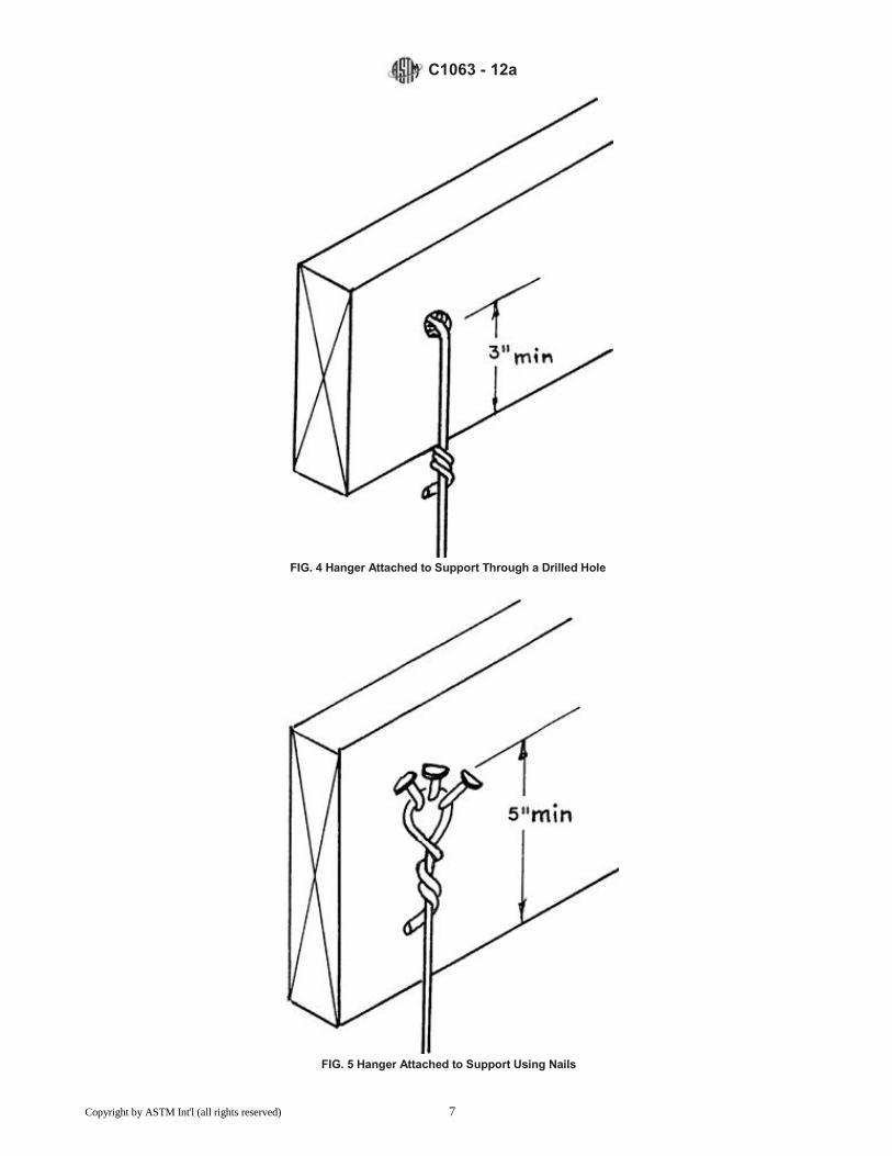
following methods: 7.3.1 A hole shall be drilled through the wood member not less than 3 in. (76 mm) above the bottom with the upper end of the wire
hanger passed through the hole and twisted three times around itself. See Fig. 4.
7.3.2 Three 12d nails shall be driven, on a downward slant, into the sides of the wood member with not less than 11⁄4 in. (31.8
mm) penetration and not less than 5 in. (127 mm) from the bottom edges, and not more than 36 in. (914 mm) on the center with the
upper end of the wire hanger wrapped around the nails and twisted three times around itself. See Fig. 5.
7.3.3 A loop shall be formed in the upper end of the wire hanger and secured to the wood member by four 11⁄2-in. (38.1-mm), not
less than 9 gauge, 0.1483-in. (3.77-mm) diameter wire staples driven horizontally or on a downward slant into the sides of the wood
members, three near the upper end of the loop and the fourth to fasten the loose end. See Fig. 6. 7.3.4 Where supports for flooring are thicker than 1
1⁄2 in. (38.1 mm) and are spaced more than 4 ft (1.2 m) on center, 1
1⁄2
in. (38.1-mm) No. 1/0 (0.3065 in.) (7.78 mm) eye screws, or equivalent, spaced not more than 3 ft (0.9 m) on centers shall be
screwed into the flooring supports with the upper end of the wire hanger inserted through the eye screws and twisted three times
around itself.
7.3.5 Two holes shall be drilled in the upper end of the flat hangers and nailed to the sides of the wood members with 12d nails
driven through the holes and clinched. Nails shall be not less than 3 in. (76 mm) above the bottom edge of the framing member.
See Fig. 7. 7.4 Attachment of Hangers to Main Runners:
7.4.1 Wire hangers shall be saddle-tied to the runners. See Fig. 1.
7.4.2 Smooth or threaded rod hangers shall be fastened to the runners with special attachments appropriate to the design.
Copyright by ASTM Int'l (all rights reserved)

C1063 - 12a
TABLE 2 Allowable Support or Hanger Wire Spacing ft-in. (mm) and Cold-Rolled Channel Main Runner Spans, ft-in. (mm)1-10
NOTE—1 in. = 25.4 mm; 1 ft2 = 0.093 m
2
Uniform Load = 12 psf (0.479 kPa)
Member Size, in. Member Weight,
(mm) lb/1000 ft (kg/m) Span Condition9,10 Member Spacing, in. (mm)
24 (610) 36 (914) 48 (1220) 60 (1520) 72 (1830)
Allowable Hanger Wire or Support Spacing, ft-in. (mm)
11⁄2 414 Single 3-6 (1070) 3-1 (940) 2-9 (840) 2-9 (790) 2-5 (740)
(38.1) (0.615) 2 or More 4-11 (1500) 4-2 (1270) 3-7 (1090) 3-2 (970) 2-11 (890)
2 506 Single 3-9 (1140) 3-3 (990) 3-0 (910) 2-9 (840) 2-8 (810)
(50.8) (0.753) 2 or More 5-2 (1570) 4-6 (1370) 4-1 (1240) 3-10 (1170) 3-7 (1090)
21⁄2 597 Single 3-11 (1190) 3-5 (1040) 3-2 (970) 2-11 (890) 2-9 (840)
(63.5) (0.888) 2 or More 5-5 (1650) 4-9 (1450) 4-4 (1320) 4.0(1220) 3-10 (1170)
Uniform Load = 15 psf (0.287 kPa)
Member Size, in. Member Weight,
(mm) lb/1000 ft (kg/m) Span Condition9,10 Member Spacing, in. (mm)
24 (610) 36 (914) 48 (1220) 60 (1520) 72 (1830)
11⁄2 414 Single 3-3 (990) 2-10 (860) 2-7 (790) 2-4 (710) 2-2 (660)
(38.1) (0.616) 2 or More 4-6 (1370) 3-8 (1120) 3-2 (970) 2-10 (860) 2-7 (790)
2 506 Single 3-6 (1070) 3-1 (940) 2-10 (880) 2-7 (790) 2-5 (740)
(50.8) (0.753) 2 or More 4-10 (1470) 4-3 (1300) 3-10 (1170) 3-6 (1070) 3-3 (990)
21⁄2 597 Single 3-8 (1120) 3-3 (990) 2-11 (890) 2-9 (840) 2-7 (790)
(63.5) (0.888) 2 or More 5-0 (1520) 4-5 (1350) 4-0 (1220) 3.9(1140) 3-6 (1070)
Allowable Spans Notes: 1 Bare metal thickness of cold-rolled main runners shall be not less than 0.0538 in. (1.367 mm).
2 Inside corner radii shall not be greater than 1⁄8 in. (3.19 mm).
3 Spans based on upper flange of main runners laterally unbraced.
4 Maximum deflection limited to 1/360 of the span length.
5 Steel yield stress, Fy, shall be not less than 33 000 psi (228 MPa).
6 Uniform load 12 psf (dry density) shall be used for portland cement plaster ceilings with plaster thicknesses up to 7⁄8 in. (22 mm) and 15 psf shall be used for ceil-
ings with plaster thicknesses over 7⁄8 in. (22 mm) and not more than 1-1⁄4 in. (32 mm). 7 “2 or More” spans refers to two or more continuous, equal spans.
8 For the “2 or More” span condition, listed spans represent the center-to-center distance between adjacent supports.
9 These tables are designed for dead loads. Specific conditions such as exterior installations in high wind areas require additional engineering.
10 Where uplift resistance is required for suspended ceilings to resist negative forces, the architect or engineer of record shall select the method to be used.
7.4.3 The lower ends of flat hangers shall be bolted to the main runners, or bent tightly around the runners and carried up and
above the runners and bolt to the main part of the hanger. Bolts shall be 3⁄8-in. (9.5-mm) diameter, round-head stove bolts. See Fig.
3.
7.5 Installation of Main Runners:
7.5.1 Minimum sizes and maximum spans and spacings of main runners for the various spans between hangers or other supports
shall be in accordance with the requirements of Table 2.
7.5.2 A clearance of not less than 1 in. (25 mm) shall be maintained between the ends of the main runners and the abutting masonry or the concrete walls, partitions, and columns. Where special conditions require that main runners let into abutting masonry or concrete construction, within such constructions maintain a clearance of not less than 1 in. (25 mm) from the ends and not less than
1⁄4 in. (6.4 mm) from the tops and sides of the runners.
7.5.3 A main runner shall be located within 6 in. (152 mm) of the paralleling walls to support the ends of the cross furring. The ends of main runners shall be supported by hangers located not more than 6 in. (152 mm) from the ends.
7.5.4 Where main runners are spliced, the ends shall be overlapped not less than 12 in. (305 mm) with flanges of channels
interlocked and securely tied near each end of the splice with double loops of 0.0625 in. (1.59 mm) or double loops of twin strands of
0.0475-in. (1.21-mm) galvanized wire. However, when the splice occurs at an expansion/control joint, the channel shall be nested
and loosely tied to hold together but still allow movement.
7.5.5 Hanger wires shall hang straight down. If an obstacle prevents this, a trapeze type device shall be used to allow hanger wires to hang straight.
7.6 Installation of Cross Furring:
7.6.1 Minimum size and maximum spans and spacings of various types of cross furring for various spans between main runners
and supports shall conform to the requirements of Table 2.
7.6.2 Cross furring shall be saddle-tied to main runners with 0.0625-in. 16 gauge (1.59-mm) galvanized wire, or a double strand of 0.0475-in. 18 gauge (1.21-mm) galvanized wire or with special galvanized clips, or equivalent attachments. (See Fig. 2.)
7.6.3 Where cross furring members are spliced, the ends shall be overlapped not less than 8 in. (203 mm), with flanges of
channels interlocked, and securely tied near each end of the splice with double loops of 0.0625-in. 16 gauge (1.59-mm) galvanized wire
or twin strands of 0.0475-in. 18 gauge (1.21-mm) galvanized wire. 7.6.4 Cross furring shall not come into contact with abutting masonry or reinforced concrete walls or partitions except, where
Copyright by ASTM Int'l (all rights reserved) 5

C1063 - 12a
FIG. 3 Flat Hanger Attached to Main Runner Using Round-Head Stove Bolt
special conditions require that cross furring be let into abutting masonry or concrete construction, the applicable provisions of 7.5.2
shall apply.
7.6.5 Main runners and cross running shall be interrupted at control (expansion) joints. However, when the splice occurs at an
expansion/control joint, the channel shall be nested and loosely tied to hold together but still allow movement. 7.7 Metal Furring for Walls:
7.7.1 Attachments for furring shall be concrete nails driven securely into concrete or into masonry joints, short pieces of 3⁄4-in. (19.1-
mm) channels used as anchors driven into masonry joints, or other devices specifically designed as spacer elements, spaced horizontally
not more than 2 ft (0.6 m) on centers. They shall be spaced vertically in accordance with horizontal stiffener spacing so that they project from the face of the wall in order for ties to be made.
7.7.2 Horizontal stiffeners shall be not less than 3⁄4 in. (19.5-mm) cold-rolled channels, spaced not to exceed 54 in. (1372 mm)
on centers vertically, with the lower and upper channels not more than 6 in. (152 mm) from the ends of vertical members and not less
than 1
⁄4 in. (6.4 mm) clear from the wall face, securely tied to attachments with three loops of galvanized, soft-annealed wire, or
equivalent devices. Approved furring is not prohibited from use in this application. 7.7.3 Vertical members shall be not less than
3⁄4 in. (19.5-mm) cold-rolled channels in accordance with the requirements of
Table 3. Vertical members shall be saddle-tied to horizontal stiffeners with three loops of 0.0475-in. (1.21-mm) galvanized soft-annealed wire, or equivalent devices, at each crossing, and securely anchored to the floor and ceiling constructions. Where furring is
not in contact with the wall, channel braces shall be installed between horizontal stiffeners and the wall, spaced horizontally not more than 2 ft (600 mm) on centers.
7.7.4 Where dampproofing has been damaged during installation of attachments, the dampproofing shall be repaired with the same material before proceeding with the installation of the furring.
7.8 Lapping of Metal Plaster Bases:
7.8.1 Side laps of metal plaster bases shall be secured to framing members. They shall be tied between supports with 0.0475-in.
(1.21-mm) wire at intervals not more than 9 in. (229 mm).
7.8.2 Metal lath shall be lapped 1⁄2 in. (12.7 mm) at the sides, or nest the edge ribs. Wire lath shall be lapped one mesh at the
sides and the ends. Lap metal lath 1 in. (25 mm) at ends. Where end laps occur between the framing members, the ends of the
sheets of all metal plaster bases shall be laced or wire tied with 0.0475-in. (1.21-mm) galvanized, annealed steel wire.
7.8.3 Where metal plaster base with backing is used, the vertical and horizontal lap joints shall be backing on backing and metal
on metal.
Copyright by ASTM Int'l (all rights reserved) 6
C1063 - 12a
FIG. 4 Hanger Attached to Support Through a Drilled Hole
FIG. 5 Hanger Attached to Support Using Nails
Copyright by ASTM Int'l (all rights reserved) 7

C1063 - 12a
FIG. 6 Hanger Attached to Support Using Staples
7.8.3.1 Backing shall be lapped not less than 2 in. (50 mm). On walls, the backing shall be lapped so water will flow to the
exterior. Backing shall not be placed between plaster base (lath) and flanges of accessories. Metal lath to metal flange contact shall be
required to ensure that flanges are mechanically locked together.
7.9 Spacing of Attachments for Metal Plaster Bases—Attachments for securing metal plaster bases to framing members shall be spaced not more than 7 in. (178 mm) apart for diamond mesh and flat rib laths and at each rib for
3⁄8 in. (9.5-mm) rib lath.
7.10 Application of Metal Plaster Bases: 7.10.1 General:
7.10.1.1Metal7.10.1.1 Metal plaster bases shall be furred away from vertical supports or solid surfaces at least 1
⁄4 in. Self furring
lath meets furring requirements; except, furring of expanded metal lath is not required on supports having a bearing surface of 15⁄8
in. or less.
7.10.1.2 The spacing of framing members for the type and weight of metal plaster base used shall conform to the requirements of Table 3. Metal plaster bases shall be attached to framing members at not more than 7 in. (178 mm) on center, along framing members except for
3⁄8-in. (9.5-mm) rib metal lath that shall be attached at each rib. Attachment penetrations between the framing members shall
be avoided (see A1.1).
7.10.1.3 Lath shall be applied with the long dimension at right angles to the supports, unless otherwise specified. 7.10.1.4 Ends of adjoining plaster bases shall be staggered.
7.10.1.5 Lath shall not be continuous through control joints but shall be stopped and tied at each side.
7.10.1.6 Where furred or suspended ceilings butt into or are penetrated by columns, walls, beams, or other elements, the edges
and ends of the ceiling lath shall be terminated at the horizontal internal angles with a casing bead, control joint, or similar device
designed to keep the edges and ends of the ceiling lath and plaster free of the adjoining vertically oriented, or penetrating elements.
Cornerite shall not be used at these locations. A clearance of not less than 3⁄8 in. (9.5 mm) shall be maintained between the bead
and all such elements.
7.10.1.7 Where load bearing walls or partitions butt into structural walls, columns, or floor or roof slabs, the sides or ends of the wall or partition lath shall be terminated at the internal angles with a casing bead, expansion/control joint, or similar device
designed to keep the sides and ends of the wall or partition lath free of the adjoining elements. Cornerite shall not be used at these internal angles. A clearance of not less than
3⁄8 in. (9.5 mm) shall be maintained from all abutting walls, columns, or other vertical
elements. 7.10.2 Attachments for Metal Plaster Bases to Wood Framing Members:
Copyright by ASTM Int'l (all rights reserved) 8

C1063 - 12a
FIG. 7 Flat Hanger Attached to Support Using Nails
TABLE 3 Types and Weights of Metal Plaster Bases and Corresponding Maximum Permissible Spacing of Supports
Maximum Permissible Spacing of Supports Center to Center, in. (mm)
Type of Metal Plaster Base Minimum Weight of Metal Plaster Base, lb/yd2(kg/m
2) Walls (Partitions) Ceilings
Wood Studs or FurringSolid PartitionsASteel Studs or FurringWood or Concrete Metal
U.S. Nominal Weights:
Diamond MeshB
2.5(1.4) 16(406)C
16(406) 16(406)C
12(305) 12(305)
3.4(1.8) 16(406)C
16(406) 16(406)C
16(406) 16(406)
Flat Rib 2.75(1.5) 16(406) 16(406) 16(406) 16(406) 16(406)
3.4(1.8) 19(482) 24(610) 19(482) 19(482) 19(482)
Flat Rib (large opening) 1.8(0.95) 24(610) 24(610) 24(610) 16(406) 16(406) 3⁄8 in. Rib 3.4(1.8) 24(610) N/A
D 24(610) 24(610) 24(610)
4.0(2.1) 24(610) N/A 24(610) 24(610) 24(610) 3⁄4 in. Rib 5.4(2.9) 24(610) N/A 24(610) 36(914) 36(914)
Welded WireB
1.14(0.62) 16(406) 16(406) 16(406) 16(406) 16(406)
1.95(1.1) 24(610) 24(610) 24(610) 24(610) 24(610)
Woven WireB
1.4(0.6) 24(610) 16(406) 16(406) 24(610) 16(406)
Canadian Nominal Weights:
Diamond MeshB
2.5(1.4) 16(406) 12(305) 12(305) 12(305) 12(305)
3.0(1.6) 16(406) 12(305) 12(305) 12(305) 12(305)
3.4(1.8) 16(406) 16(406) 16(406) 16(406) 16(406)
Flat Rib 2.5(1.4) 16(406) 12(305) 12(305) 12(305) 12(305)
3.0(1.6) 16(406) 16(406) 16(406) 16(406) 131⁄2 (343) 3⁄8 in. Rib 3.0(1.6) 19(482) N/A 16(406) 16(406) 16(406)
3.5(1.9) 24(610) N/A 19(482) 19(482) 19(482)
4.0(2.1) 24(610) N/A 24(610) 24(610) 24(610)
A Where plywood is used for sheathing, a minimum of 1⁄8 in. (3.2 mm) separation shall be provided between adjoining sheets to allow for expansion.
B Metal plaster bases shall be furred away from vertical supports or solid surfaces at least 1⁄4 in. Self-furring lath meets furring requirements; except, furring of expanded
metal lath is not required on supports having a bearing surface of 15⁄8 in. or less. C These spacings are based on unsheathed walls. Where self-furring lath is placed over sheathing or a solid surface, the permissible spacing of supports shall be no
more than 24 in. (610 mm). D Not applicable.
7.10.2.1 Lath shall be attached to framing members with attachments spaced not more than 7 in. (178 mm) on centers along supports.
Copyright by ASTM Int'l (all rights reserved) 9

C1063 - 12a TABLE 4 Spans and Spacing of Cold-Rolled Channel Cross- Furring Members
A, B, C, D, E, F
Design Load, Allowable Span,
12 psf (575 Pa) Main Runners or Supports
Ft-in. (mm)
Member Depth Spacing, in. (mm) Simple Span Two or More SpansG,H
3⁄4 (19) 13.5 (343) 2-9 (840) 3-5 (1040)
16 (406) 2-7 (790) 3-3 (990)
19 (483) 2-7 (740) 3-0 (910)
24 (610) 2-3 (690) 2-10 (860)
11⁄2 (38) 13.5 (343) 4-6 (1370) 5-8 (1730)
16 (406) 4-3 (1300) 5-5 (1650)
19 (483) 4-0 (1220) 5-1 (1550)
24 (610) 3-8 (1120) 4-9 (1450) A Bare metal thickness of cold-rolled members shall not be less than 0.0538 in.
(1.367 mm). B Inside corner radii shall not be greater than 1⁄8 in. (3.17 mm).
C Spans based on upper flange of cross-furring laterally unbraced.
D Maximum deflection limited to 1⁄360
th of span length unbraced.
E Steel yield stress, Fy, shall not be less than 33 000 psi (228 MPa).
F Tabulated spans apply only to cross-furring with webs oriented vertically.
G “Two or more” spans refers to two or more continuous, equal spans.
H For the “two or more” span conditions, listed spans represent the center-to-
center distance between adjacent supports.
7.10.2.2 Diamond-mesh expanded metal lath, flat-rib expanded metal lath, and wire lath shall be attached to horizontal wood
framing members with 11⁄2-in. (38.1-mm) roofing nails driven flush with the plaster base and attached to vertical wood framing
members with 6d common nails, or 1-in. (25-mm) roofing nails driven to a penetration of not less than 3⁄4 in. (19.1 mm), or 1-in.
(25-mm) wire staples driven flush with the plaster base. Staples shall have crowns not less than 3
⁄4 in. (19.05 mm) and shall engage
not less than three strands of lath and penetrate the wood framing members not less than 3⁄4 in. (19.05 mm). When metal lath is
applied over sheathing, use fasteners that will penetrate the structural members not less than 3⁄4 in. (19 mm).
7.10.2.3 Expanded 3⁄8 in. (9.5 mm) rib lath shall be attached to horizontal and vertical wood framing members with nails or
staples to provide not less than 13⁄4-in. (44.5-mm) penetration into horizontal wood framing members, and
3⁄4-in. (19.1-mm)
penetration into vertical wood framing members.
7.10.2.4 Common nails shall be bent over to engage not less than three strands of lath, or be bent over a rib when rib lath is installed.
7.10.2.5 Screws used to attach metal plaster base to horizontal and vertical wood framing members shall penetrate not less than 5⁄8 in. (15.9 mm) into the member when the lath is installed and shall engage not less than three strands of lath. When installing
rib lath, the screw shall pass through, but not deform, the rib. 7.10.3 Attachments for Metal Plaster Bases to Metal Framing Members:
7.10.3.1 Except as described in 7.10.3.2, all metal plaster bases shall be securely attached to metal framing members with
0.0475-in. 18 gauge (1.21-mm) wire ties, clips or by other means of attachment which afford carrying strength and resistance to
corrosion equal to or superior to that of the wire. 7.10.3.2 Rib metal lath shall be attached to open-web steel joists by single ties of galvanized, annealed steel wire, not less than
0.0475 in. (1.21 mm), with the ends of each tie twisted together 11⁄2 times.
7.10.3.3 Screws used to attach metal plaster base to metal framing members shall project not less than 3⁄8 in. (9.5 mm) through
the metal framing member when the lath is installed and shall engage not less than three strands of lath. When installing rib lath, the screw shall pass through, but not deform, the rib.
7.10.4 Attachments for Metal Plaster Bases to Concrete Joists—Rib metal lath shall be attached to concrete joists by loops of 0.0800-in. (2.03-mm) galvanized, annealed steel wire, with the ends of each loop twisted together.
7.10.5 Metal plaster bases shall be attached to masonry or concrete with power or powder actuated fasteners or a combination
of power or powder actuated fasteners and hardened concrete stub nails. One power or powder actuated fastener shall be located
at each corner and one at the mid point of the long dimension adjacent to the edge of the metal plaster base sheet. The balance
of the sheet shall be fastened with power or powder actuated fasteners or hardened concrete stub nails. The fasteners shall be
installed in rows not more than 16 in. (406 mm) on center and spaced vertically along each row not more 7 in. (178 mm) on center.
All fasteners shall be corrosion resistant and shall be not less than 3⁄4 in. (19 mm) long, with heads not less than
3⁄8 in. (9.5 mm)
wide.
7.11 Application of Accessories :
7.11.1 General—All metal accessories shall be installed in such a manner than flanges and clips provided for their attachment are
completely embedded in the plaster.
7.11.1.1 Accessories shall be attached to substrate in such a manner as to ensure proper alignment during application of plaster.
Flanges of accessories shall be secured at not more than 7 in. (178 mm) intervals along supports. 7.11.2 Corner Beads—Corner beads shall be installed to protect all external corners and to establish grounds.
Copyright by ASTM Int'l (all rights reserved)

C1063 - 12a
7.11.2.1 External Corner Reinforcement —External corner reinforcement shall be installed to reinforce all external corners where
corner bead is not used. Where no external corner reinforcement or corner bead is used, lath shall be furred out and carried around
corners not less than one support on frame construction.
7.11.3 Casing Beads—Nonload-bearing members shall be isolated from load-bearing members, and all penetrating elements,
with casing beads or other suitable means, to avoid transfer of structural loads, and to separate from dissimilar materials.
7.11.4 Control Joints-General—Control joints shall be formed by using a single prefabricated member or fabricated by
installing casing beads back to back with a flexible barrier membrane behind the casing beads. The separation spacing shall be not
less than 1⁄8 in. (3.2 mm) or as required by the anticipated thermal exposure range and shall be in conformance with 7.10.1.5.
7.11.4.1 Control Joints—Control (expansion and contraction) joints shall be installed in walls to delineate areas not more than 144
ft2(13.4 m
2) and to delineate areas not more than 100 ft
2(9.30 m
2) for all horizontal applications, that is, ceilings, curves, or angle type
structures.
7.11.4.2 The distance between control joints shall not exceed 18 ft (5.5 m) in either direction or a length-to-width ratio of 21⁄2 to 1.
A control joint shall be installed where the ceiling framing or furring changes direction.
7.11.4.3 A control joint shall be installed where an expansion joint occurs in the base exterior wall.
7.11.4.4 Wall or partition height door frames shall be considered as control joints.
7.11.5 Foundation Weep Screed—Foundation weep screed shall be installed at the bottom of all steel or wood framed exterior walls
to receive lath and plaster. Place the bottom edge of the foundation weep screed not less than 1 in. (25 mm) below the joint formed by
the foundation and framing. The nose of the screed shall be placed not less than 4 in. (102 mm) above raw earth or 2 in. (51 mm)
above paved surfaces. The weather resistive barrier and lath shall entirely cover the vertical attachment flange and terminate at the
top edge of the nose or ground flange.
8. Keywords
8.1 ceiling; expansion control joints; lath; plaster; screed; suspended ceiling; walls
ANNEX
(Mandatory Information)
A1. GENERAL INFORMATION
A1.1 All wood-based sheathing shall be installed with a minimum 1⁄8-in. (3.2-mm) gap around all panel edges and between
openings for doors and windows.
NOTE A1.1—This 1⁄8-in. (3.2-mm) gap is intended to accommodate expansion. Linear expansion that is not accommodated by an expansion gap can
cause stress on the stucco membrane resulting in stucco cracks.
Copyright by ASTM Int'l (all rights reserved) 11

C1063 - 12a
A1.2 Expansion Joints shall be used to accommodate some degree of movement in the stucco membrane caused by movement of
the building or its components to minimize damage to the stucco and weather resistive barrier. Control Joints shall be installed to
minimize stress due to stucco curing and drying shrinkage and minor movement, along predetermined, usually straight lines and as a
screed to aid in stucco thickness control.
SUMMARY OF CHANGES
Committee C11 has identified the location of selected changes to this specification since the last issue, C1063 - 11ab, that may impact the use of this specification. (Approved Dec. 1, 2011)April 15, 2012.)
(1)Added 7.10.1.1 and renumbered subsequent sections. ) Revised 7.10.1.2 and added the term water barrier to the terminology section.
ASTM International takes no position respecting the validity of any patent rights asserted in connection with any item mentioned in this standard. Users of this standard are expressly advised that determination of the validity of any such patent rights, and the risk of infringement of such rights, are entirely their own responsibility.
This standard is subject to revision at any time by the responsible technical committee and must be reviewed every five years and if
not revised, either reapproved or withdrawn. Your comments are invited either for revision of this standard or for additional standards and
should be addressed to ASTM International Headquarters. Your comments will receive careful consideration at a meeting of the
responsible technical committee, which you may attend. If you feel that your comments have not received a fair hearing you should
make your views known to the ASTM Committee on Standards, at the address shown below.
This standard is copyrighted by ASTM International, 100 Barr Harbor Drive, PO Box C700, West Conshohocken, PA 19428-2959,
United States. Individual reprints (single or multiple copies) of this standard may be obtained by contacting ASTM at the above
address or at 610-832-9585 (phone), 610-832-9555 (fax), or [email protected] (e-mail); or through the ASTM website
(www.astm.org). Permission rights to photocopy the standard may also be secured from the ASTM website (www.astm.org/
COPYRIGHT/).
Copyright by ASTM Int'l (all rights reserved) 12