designer, manufacturer and distributor · designer, manufacturer, and distributor ... electric,...
TRANSCRIPT

DESIGNER, MANUFACTURER AND DISTRIBUTOR
MAINTENANCE BOOKLETEN
An ISO 9001-certifi ed site for the design, marketing and distribution of bikes
EN

DESIGNER, MANUFACTURER, AND DISTRIBUTOR
The CYCLEUROPE Group is the designer, manufacturer and distributor of all-purpose bikes and electric bikes.The Group owns the following brands: Bianchi, Gitane, Puch, DBS, Monark, Crescent, Kildemoes, Everton and has a license for Peugeot. Cycleurope offers a large collection aimed at all types of users: Electric, City, Trekking, Mountain Bike, Hybrid Bike, Racing, Fitness, and Junior.
The Cycleurope Group is headquartered in Romilly-sur-Seine (10), France, where it
Thank you for putting your trust in us.The standard relevant to your bike is indicated on your bike:
Find our brands and the list of retailers at: www.cycleurope.fr
has a R&D site, laboratory, and production facility. This site is the electric bike R&D center of competence for the entire Group. Market leader and postal service partner for a number of years, Cycleurope is constantly innovating to meet the challenges of mobility.
Cycleurope also has its own retail chain, VELO & OXYGEN.
Cycleurope is present in more than 50 coun-tries, has 3 production facilities in Europe and markets more than one million bikes.
ISO 4210:2014 - C City and hybrid bike
ISO 4210:2014 - M Mountain bike
ISO 4210:2014 - R Racing bike
ISO 4210: 2014 - Y Bike for young adults
ISO 8098: 2014 Bike for young children
EN 15194 Electric bikes
EN 16054 cat 1 BMX for cyclists whose the weight is less than or equal to 45 kg
EN 16054 cat 2 BMX for cyclists whose the weight is greater than 45 kg
EN
38

This booklet was designed to help you fully enjoy your bike. We urge you to read it carefully, as it will guide you through the periodic checks to be carried out and help you perform basic maintenance on your bike. If you have any questions on bike operation and maintenance, do not hesitate to consult your nearest retailer.
LIABILITYThe bike owner is liable for any incidents that may occur as a result of failure to observe the instructions in this booklet. If you have any questions on maintenance or safety operations, please contact your retailer, who will perform these operations according to best practices.
AFTER-SALES AND MANTENANCE SERVICEYour Cycleurope retailer can be trusted for all maintenance and repair operations, or the provision of spare parts.When replacing components, you must use
Danger / For your safety Indicates basic safety regulations and standards. Not observing these regulations can lead to accidents, falls, and injury to the user.
Danger / For your safety Use of your bike outside of these normal conditions can be dangerous. The user assumes full responsibility for any potential accidents and injuries that may be suffered by the user or third parties under such circumstances. Cycleurope shall not be liable for uses that do not comply with the structural features of its bikes.
Warning / ImportantIndicates important technical warnings, which should be strictly followed for your bike to be used correctly.
Please read this booklet carefully so that you can enjoy your bike and ride it in complete safety.
The information contained in this booklet should be considered as guidelines to ensure safe operation but it does not substitute the safety regulations and laws in force.
original parts to preserve the performance and reliability of the bike. This operation must be performed by your approved retailer.The maintenance and replacement of acces-sories and spare parts provided and installed by the bike manufacturer must be performed by a qualifi ed professional in line with the manufacturer's recommendations.
1 FOREWARD
LEGEND:
EN
39

Carefully read all of the warnings and any notes in this booklet before using your bike. Keep this booklet near the bike so that it can be referenced at any time. Make this booklet available to anyone else who may use your bike.The product and its use must comply with the regulations in force.
► For safe use, wearing an approved helmet as well as protective and/or refl ective gear is recommended.► Wear a (refl ective) safety vest when riding in rural areas at night or during the day when visibility is poor.► Never ride without lights at night or in bad weather, so as to remain visible to other road users.► Wear visible clothing or refl ective elements so that you can be seen in time by other road users.► Wear shoes with solid and non-slip soles.► Do not wear loose clothing around the knees that could get caught around the wheels.► Wear protective clothing such as hard-wearing shoes and gloves.► Respect the requirements of the national regulations in force when the bike is to be used on a public road (lights, signaling and bell, for example).
Danger / Safety regulation For safety purposes, always use original parts for the critical components.
Warning / ImportantCertain countries insist that the bike is delivered "ready to ride". In this case, if some of your bike's components are not assembled, please contact your approved retailer.
If legislation permits the marketing of partial-ly assembled bikes, the components that are delivered unassembled must be assembled in line with the manufacturer's instructions provided with the product.
► Always ride with two hands on the handlebars.► Do not use headsets or headphones to listen to audio recordings or music. Do not use the telephone.► In wet weather, where visibility and grip are reduced, braking distances are extended, and the user must adapt their speed and anticipate braking.► Do not use your bike under the infl uence of alcohol, medication, or illegal substances.
2
2.1
2.2
SAFETY ADVICE
Basic safety advice
For your safety
EN
40

► Ensure that the child learns and under-stands the rules for safely and responsibly using the bike in any environment.► Ensure that the child is properly trained in how to use a children's bike, particularly concerning the safe use of the brake system.► The legal guardian is responsible for the child's safety and any potential damage
Warning / ImportantNever install or remove the stabilizers by removing other parts of the bike (for example, the wheel locking nuts). Never use the bike with just one stabilizer. Use the bike with stabilizers on fl at ground.
caused by the child. Regularly ensure that the bike is correctly adjusted to the child's size.► The stabilizers must be installed and adjusted by a qualifi ed professional.
2.3 For the attention of parents and legal guardians
EN
41

Saddle
luggage carrier
Seatpost
Light Rim
Stand
Light
Pedal
ArcBrake leverHandlebar grips
Chain
Dynamo front hub
► City bike and hybrid bike (trekking / hybrid)
Bikes designed to be used on public roads and paved paths (roads, cycle tracks and paths). These bikes are not designed for off-road use or for competitions but should be used mainly as a mode of transport or for recreational purposes. They have a saddle height of at least 635 mm.
3 TYPES OF USE
EN
42

Saddle
Rim
Seatpost clamp
Brake disk
Brake caliper
Frame
Tire
Suspension fork
Radius
Chain
Shock absorber
Brake lever
Dérailleur gears
Seatpost
► Mountain bike
Bikes designed to be used both on and off-road. They are fitted with an adequately strength-ened frame, and more specifically, have broad spike tires and a wide gear ratio. They have a saddle height of at least 635 mm.
Warning / ImportantOff-road use is understood to be normal and reasonable use of the bike on land that can be qualifi ed as all-terrain. This excludes any extreme off-road use, for example, competitions, down hill, freestyle, etc.Cycleurope reminds you that the user is fully liable for any damages, both physi-cal and material, sustained by the user or any third parties as a result of technical defects in your bike or any of its components under such conditions.
EN
43

Cogset�
Steeringblock
Brake leverGear
changer
Saddle
Front dérailleur
Brake caliper
Frame
Crankset
Arc
Stem
Rear dérailleur
Seatpost
► Racing bike
These bikes are designed to be used by beginners at high speed on public roads. They are not intended for use in regulated competitions. They have a saddle height of at least 635 mm. These bikes are not designed for off-road use.
EN
44

Tire
Brake lever
Frame
Brake
Basket
Fork
Handle grips
Stabilizer Pedal
► Bike for young children
Bikes designed to be used on public roads by young adults weighing less than 40 kg. The saddle height is between 635 mm and 750 mm.
Stem
Pedal
Frame
Tire
Fork
Brake
Rim
Handle grips
Rear dérailleur
Crankset
Freewheel
Saddle
Saddle
Seatpost clamp
Mudguard
Seatpost
Chain protector
► Bike for young adults
Bikes have a maximum saddle height between 435 mm and 635 mm (typical cyclist weight: 30 kg).
EN
45

Tire
Mudguard
Saddle
Battery
Baggage holder
Display
Front light
Stand
Frame
Motor
Cable bundle
► Electric bikes
EN
Bikes that are fitted with pedals and an auxiliary electric motor and that are only propelled forward via this auxiliary electric motor.
46

Brake lever
Chain
Brake
Crankset
Hub
RadiusFreewheel
Handlebar
Tire
Fork
Stem
Rim
Handle grips Saddle
Frame
Seatpost
► BMX
Bikes intended for use on all types of terrain, such as roads, cycle tracks, and ramps, and designed and equipped for activities such as acrobatic tricks, but excluding regulated compe-titions. The saddle can be adjusted to give a minimum saddle height that is greater than or equal to 435 mm.There are two BMX categories:a) BMX category 1, designed for cyclists whose weight is lower than or equal to 45 kg;b) BMX category 2, designed for cyclists whose weight is greater than 45 kg.It does not apply to BMX bikes used in regulated competitions.
Warning / ImportantCycleurope is not liable in the event of improper use.
EN
47

To determine your saddle height, sit on the bike, put your heel on the pedal in the low position, crank parallel to the seatpost. When your leg is straight, the saddle height is correct (fi g. A).
4.2 - 1: Adjusting the height
Insert the seatpost (A) into the saddle tube (B). Adjust the height of the saddle tube depending on the user's body type, but without exceeding the minimum insertion mark on the the saddle tube. For some mountain bikes and racing biles, you can adjust the length of the integrated seatpost (ISP).Once the desired height is obtained, re-tighten the screw (C) to the torque indicated on the clamp, or if it is not present, the torque indicated in the recommended torque tightening values table (page 20).
When pedaling, the knee will be slightly bent. (fi g. B).
4
4.1
4.2
PREPARATION FOR USE
Adjusting the bike to your height
Adjusting the saddle
EN
Warning / ImportantFor your safety, the saddle must not be extended beyond the marking indicated on the seatpost.The saddle can be adjusted to give a saddle height that is greater than or equal to 635 mm.
Note: Bikes for young childrenThe saddle can be adjusted to give a saddle height that is greater than 435 mm and less than or equal to 635 mm.
H: maximum saddle height1: minimum depth mark for inserting the seat-post into the frame 2: ground
A
C
B
48

4.2 - 2: Longitudinal adjustment (pushing back the saddle)
4.2 - 3: Protecting the springs under the saddle
4.2 - 4: Suspended seatpost
EN
Warning / ImportantSuspended seatposts are usually adjusted according to the weight of the user. They must be removed to carry out this adjustment. To perform this operation, please always consult a qualifi ed professional.
Loosen the nut (G). Slide the saddle on the carriage (K) to obtain the desired position.Check the horizontalness of the saddle and that it is correctly aligned with the bike.Tighten the nut (G). Refer to the RECOMMENDED TORQUE TIGHTENING VALUES section if there are no manufacturer's instructions.The carriage (L) must be fully fi tted onto the seatpost and the min-max markings of the saddle carriage position must be respected.
Danger / Safety regulation Ensure that the coil springs under the saddle are protected before mounting a child's seat to prevent fi ngers becoming jammed.
4.3. Adjusting the arc and stem (handlebar)
The handlebar is comprised of an arc and a stem. Adjustments to handlebar height depend on the type of bike and type of path. Changing the height of the handlebar influ-ences the seating position of the bike.There are mainly two types of stem:
► quill stem, which locks inside the head tube with an expander.
► stem called "ahead set", held by the clamps on the outside of the head tube.
4.3 - 1: Adjusting a quill stem (fi g.1)
► Loosen the screw of the expander (A) 2 turns counter clockwise using an Allen key.
► Lightly tap the screw with a mallet to release the corner of the expander.
► Adjust the quill stem to the desired height, without exceeding the minimum insertion mark.
► Tighten the screw of the expander, check-
ing that the handlebar is perpendicular to the front wheel. If the screw is too tight, it can break. This is very dangerous to your safety and can result in injury and damage to the bike.
► Use the torque value indicated on the stem or, if it is not present, the value indicated in the RECOMMENDED TORQUE TIGHTENING VALUES table.
49

EN
4.3 - 2: Adjusting a stem with the "Ahead set" system
4.3 - 3: Adjusting the position and direction of the handlebar
4.3 - 4: Adjusting the tilt of adjustable stems
This stem is directly fitted on the pivot of the fork. It must be in direct contact with the upper part of the headset. For any potential adjustment to the height of the stem, please see your Cycleurope retailer.
Follow these steps to align the handlebar with the front wheel:
► Loosen the screws on the front part of the stem, turning them counter clockwise using an Allen key.
► Turn the handlebar to the desired position. The handlebar must be placed exactly in the
Some types of handlebar stems allow for the handlebar to be tilted. The tightening screws to set the handlebar tilt can be found on the
middle of the stem.
► Re-tighten the screws, turning them clockwise using an Allen key (for the torque value, refer to the RECOMMENDED TORQUE TIGHTENING VALUES section).
side of the joint, or on the lower or upper part of the stem. There are also models with addi-tional locking catches or alignment screws.
Danger / Safety regulation Be aware of the insertion limit (B) of the quill stem. For your safety, the quill stem must not extend beyond the minimum insertion mark on the tube.
Fig. 1
Warning / ImportantThis is a safety device. For any potential adjustment, please see your Cycleurope retailer.
50

EN
After adjusting your stem to its maximum height (view 1), always check that the "MINI INSERT" inscription does not appear above the steering nut by lifting the plug "A".
Warning / ImportantEnsure that the minimum insertion mark of the quill stem is not visible.
Warning / ImportantUse of any type of aerodynamic extension on the handlebar can have a negative infl uence on the response time of the cyclist when braking or on bends.
4.3 - 5: Stems with steering cover
If the bike is fitted with suspensions, they can be adjusted by measuring the sinking of the shock absorber and/or fork. The shock
absorber setting depends on the weight of the cyclist and the use of the bike.
Warning / ImportantThe suspension fork and shock absorbers must never be disassembled by the user. This operation must be performed by a qualifi ed expert.
4.4 Adjusting the suspensions
51

EN
Warning / ImportantThe good condition of wearable parts such as the rims, brakes, tires, steering, and transmission must be checked by the user before each use and regularly checked, maintained, and adjusted by a qualifi ed professional in line with the manufacturer's recommendations.Ensure that the wheel nuts are correctly tightened, the lighting and signaling system (front and rear) is working, the seatpost, saddle, and stem are correctly positioned and tightened, the bell works, and all of the attachments are correctly tightened. Please refer to the relevant sections for more information on these points.
Warning / ImportantFor composite (carbon) componentsSpecifi c precautions must be taken for all operations on carbon components (assem-bly, maintenance, transport, etc.). All carbon components must be regularly and care-fully inspected, particularly after a fall or an accident, in order to detect any potential signs of a crack, deformation, wear, etc. If in doubt, contact your Cycleurope retailer.
Note:Carbon components must never be subjected to strong temperature variations, as they may break and result in the user falling off the bike.
Warning / ImportantAs with any mechanical component, a bike is subject to heavy constraints and wear. Different materials and components can react differently to wear or fatigue. If the intended lifespan for a component is exceeded, it can break in a single stroke, which could then lead to cyclist injuries. Cracks, scratches, and discolorations in areas subject to heavy constraints indicate that the component has exceeded its lifespan and must be replaced.Consequently, periodic checks of all bike components by a qualifi ed professional are recommended, more specifi cally the frame, fork, and suspension attachments (if present).
POINTS TO CHECKBefore each use Condition of the rims/degree of wear on the sides if rim brakes are present
Quick release and tightening of wheel nuts
Front and rear brakes
Tires: wear, pressure
Operation of the lighting and
signaling system
Bolt tightness
4.5 Checks before use
52

EN
operations involving screw and nut assembliesFor all assembly operations, appropriate wrenches must be used and the recommended torque tightening not exceeded.It is important to respect the correct torque tightening values for the bike attachment systems – nuts, bolts, screws. Too low, and the attachment may not remain tight. To high, and the screw could be damaged, stretched, warped, or broken. In this case, as with others, an incorrect torque value can lead to the failure of a component and you risk losing control of the bike and falling off.During tightening or loosening, if the threads appear damaged, the screw or nut must be replaced.If you notice a difference between the manufacturer's recommendations for a component and those found in this manual, please ask your retailer.
Recommended torque tightening values for attachment systemsUsing a torque wrench calibrated to tighten the important components of your bike is recom-mended. Refer to the manufacturer's recommendations or, if not present, follow the recom-mendations below:
* Using a mounting paste on the carbon is recommended
Tightening carbon fi ber parts
Screw assembly Torque tightening
Crank, steel 30 Nm
Crank, aluminum 40 Nm
Pedals 40 Nm
Front wheel axle nut 25 Nm
Rear wheel axle nut 40 Nm
Stem expander 8 Nm
Aheadset stem locking screw 9 Nm
M8 seatpost locking screw 20 Nm
M6 seatpost locking screw 14 Nm
Seatpost attachment lock 20 Nm
Brake blocks 6 Nm
Dynamo support 10 Nm
Seatpost clamp for carbon frame 5 Nm*
Bottle holder on carbon frame 2 Nm
Screw assembly Torque tightening
Lock collar screw of the front dérailleur 3 Nm*
Fastening screw of the shift lever 3 Nm*
Fastening screw of the brake lever 3 Nm*
Handlebar-stem fl ange 5 Nm*
Stem fastener on the fork pivot 4 Nm*
53

EN
* Using a mounting paste on the carbon is recommended
Standard torque tightening for screw assemblies
Types of screws Marking of screws
8.8 10.9 12.9
M4 2.7 Nm 3.8 Nm 4.6 Nm
M5 5.5 Nm 8.0 Nm 9.5 Nm
M6 9.5 Nm 13.0 Nm 16.0 Nm
M8 23 Nm 32.0 Nm 39.0 Nm
M10 46 Nm 64.0 Nm 77.0 Nm
Screw assembly Types of screws
Maximum torque tightening
Seat clamp, not tightened M5 4 Nm*
Seat clamp, not tightened M6 5.5 Nm*
Dérailleur screw eyelet M10 x 1 8 Nm*
Bottle holder M5 4 Nm*
To ensure that the handlebar, stem, saddle and seatpost, wheels, and aerodynamic extensions or other parts are correctly fi tted, it is recommended that you use appropriate wrenches and apply a clamping strength in line with the specifi c torque tightening value of each of the components from the different
types of bikes highlighted by the manufactur-er in the manual that comes with the product or that is engraved directly on the compo-nent. Failing this, using the torque tightening values in this booklet is recommended.If in doubt, contact your retailer.
54
EN
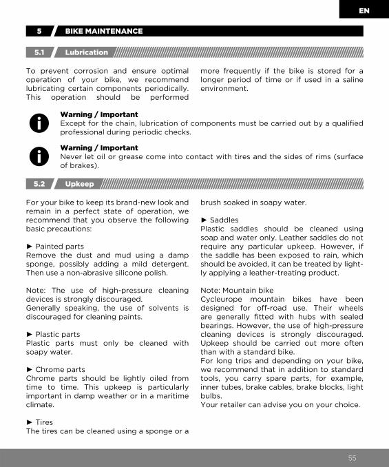
Warning / ImportantExcept for the chain, lubrication of components must be carried out by a qualifi ed professional during periodic checks.
Warning / ImportantNever let oil or grease come into contact with tires and the sides of rims (surface of brakes).
5 BIKE MAINTENANCE
To prevent corrosion and ensure optimal operation of your bike, we recommend lubricating certain components periodically. This operation should be performed
For your bike to keep its brand-new look and remain in a perfect state of operation, we recommend that you observe the following basic precautions:
► Painted partsRemove the dust and mud using a damp sponge, possibly adding a mild detergent. Then use a non-abrasive silicone polish.
Note: The use of high-pressure cleaning devices is strongly discouraged.Generally speaking, the use of solvents is discouraged for cleaning paints.
► Plastic partsPlastic parts must only be cleaned with soapy water.
► Chrome partsChrome parts should be lightly oiled from time to time. This upkeep is particularly important in damp weather or in a maritime climate.
► TiresThe tires can be cleaned using a sponge or a
more frequently if the bike is stored for a longer period of time or if used in a saline environment.
brush soaked in soapy water.
► SaddlesPlastic saddles should be cleaned using soap and water only. Leather saddles do not require any particular upkeep. However, if the saddle has been exposed to rain, which should be avoided, it can be treated by light-ly applying a leather-treating product.
Note: Mountain bikeCycleurope mountain bikes have been designed for off-road use. Their wheels are generally fi tted with hubs with sealed bearings. However, the use of high-pressure cleaning devices is strongly discouraged. Upkeep should be carried out more often than with a standard bike.For long trips and depending on your bike, we recommend that in addition to standard tools, you carry spare parts, for example, inner tubes, brake cables, brake blocks, light bulbs.Your retailer can advise you on your choice.
5.1
5.2
Lubrication
Upkeep
55
EN
Warning / ImportantLong-term storageIf your bike will be out of use for a period of time, we recommend storing it in a dry place, preferably hung up so as not to damage the tires.
Composite materialsEnsure that you do not expose your bike to high temperatures in a confi ned envi-ronment if it has components made of composite materials, as you risk altering the quality of these components.
6 OPERATING AND ADJUSTING THE BRAKES
The front brake is controlled by the left brake lever.The rear brake is controlled by the right brake lever (unless there are specifi c regula-tions governing certain countries, such as the United Kingdom, Japan, etc.)The brakes are the cyclist's main safety component. They must be checked before each use and regularly maintained and adjusted. The casings must not be subjected to closed trajectory angles, so that the cables slide with the minimum friction.Damaged, frayed, and rusted cables must be changed immediately.If the cable is handled, the torque to be applied is 5 to 7 N.m (cable tightened on
caliper).These adjustments should be made by a qualifi ed professional.If friction components are replaced in the brake system, using original parts guaran-tees that your bike maintains its high perfor-mance. This operation must be performed by a qualifi ed expert.
In wet weather, where visibility and grip are reduced, braking distances are extended, and the user must adapt their speed and anticipate braking.
5.3 Storing the bike
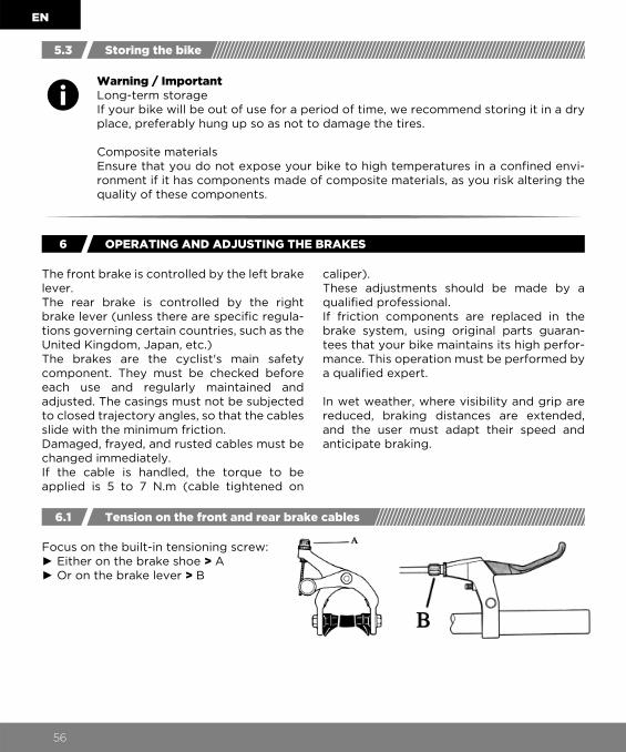
6.1 Tension on the front and rear brake cables
Focus on the built-in tensioning screw:► Either on the brake shoe > A► Or on the brake lever > B
56

EN
6.2
6.3
Adjusting the brake blocks
Replacing the brake blocks
► Align the blocks with the rim: fi g. A► The block must be tilted slightly according to the rotation direction of the wheel: fi g. B► The amount of space between the blocks and the rim must be 3 to 4 mm: fi g. C► The blocks must never touch the tires.
The blocks and brake linings are wearable parts. To ensure your bike's ideal braking performance, regularly check for wear on the blocks, on each caliper.If the rubber is completely worn, always replace both blocks at the same time.Note: If the original blocks do not have tread,
even when new, replace them when the rubber block is only3 mm from the metal bracket.
Fig. B
Fig. C
Fig. A
Remove the block to be replaced, using a wrench to loosen the fastening nut and washer.If your brakes are fitted with stops, keep them to reuse on reassembly.Determine whether your replacement blocks are "common" or "directional".Note: Directional brake blocks must be mounted facing the correct way, as the design and structure are different at each end.
Fastening screw and nut
Warning / ImportantFor all operations on the brake system, we recommend that you see your Cycleurope retailer, who is qualifi ed to perform these operations.
Warning / ImportantSpecifi c brake blocks are required on carbon rims. Please consult your approved Cycleurope retailer, who will advise you.
57

EN
6.4
6.5
Roller brake
Mechanical and hydraulic disc brakes
The roller brakes require little maintenance, since the body of the brake is located inside the hub. However, it is a wearable part. The
There are two types of disc brakes: hydraulic and mechanical. The pads must be replaced periodically.
After each adjustment, perform a brake test by pushing the bike forcefully and pulling the
inner lining must be replaced periodically. This operation must be performed by your repairman.
brake lever. Only use the bike if the brakes are working correctly.
Warning / ImportantThe roller brakes will heat up quickly if pressure is applied for a long period. The braking power is reduced and the brake can stop completely. Adapt your riding style.
Warning / ImportantWe advise you to consult your approved retailer for the assembly, replacing, and upkeep of your disc brakes.
Warning: the braking distance is increased in wet weather.
Warning / ImportantAt the end of braking, the discs and calipers can become very hot and can therefore cause serious burns if touched. After braking, wait 30 minutes before touching the brake disc or caliper.
Warning / ImportantTo prevent any chance of an accident, the brake discs should be adjusted by a specialist retailer.
Warning / ImportantNever touch moving brake discs with your fi ngers during assembly, disassembly, and maintenance on the bike, as this could lead to serious injury.
Warning / ImportantEnsure that the brake discs remain clean and that they do not have any trace of oil.They should be cleaned regularly with a degreasing product to ensure consistent braking.
Warning / ImportantAs this is a delicate operation on a safety component, please consult a qualifi ed professional.
6.5 - 1: Adjusting the brake discs (rotors)
58

EN
Warning / ImportantRegularly check the wear on your bike's brake pads.Ensure that the brake pads remain clean and that they do not have any trace of oil.Before each use, check the sealing on hoses and connectors.Stop using the bike immediately if there is a loss of liquid from the brake system and have a qualifi ed professional carry out the necessary repairs before using the bike again.If you use the bike despite the fl uid loss, the brake system may suddenly cease to work.
6.5 - 2: Bleeding the hydraulic brakes
6.5 - 3: Backpedal brake
The brake oil must be replaced once a year, or more often if the bike is used intensively, or the brake system could become damaged.
The brake is activated when the user pedals backwards. The chain actually activates the brake. That's why you should ensure that the
This operation requires special tools and must be performed by your approved retailer.
chain tension is correct and that it cannot derail.
Warning / ImportantTo optimize the braking performance of a backpedal system, the pedal must be in a horizontal position (not with one pedal on top and the other below).Be careful on long descents. Use the front brake too, as the effi ciency of the back-pedal brake can be reduced by the intense heat generated by a prolonged descent. Finally, always let a backpedal brake cool down before touching it.
59

EN
Warning / ImportantThe chain is a wearable part. A worn chain could break and lead to a fall. Always have a qualifi ed professional replace worn chains before using the bike again.
7 TRANSMISSION
If your bike has a dérailleur, the chain is auto-matically tensioned.For single-speed bikes or bikes with built-in gear change in the hub, the chain tension must be checked periodically. An incorrectly tensioned chain could lead to derailment and a fall. A chain that is too tight will damage the bike.For correct operation, the central part of the chain must have a distance of 10 mm sepa-rating the sprocket from the pedal during vertical movement.
The tensioning and adjustment of all other types of transmission must be carried out by a qualifi ed professional.
The front and rear dérailleurs allow you to shift gears easily.
After a certain period of time, the controls should be adjusted, as they are subjected to normal decline.The dérailleurs can be adjusted using two screws (A and B), which limit the extreme positions of the dérailleurs. Turn the two adjustment screws so that all of the gears shift, without the chain being released from the freewheel or chainrings.
7.1
7.2
Tensioning and adjusting the chain or any other type of transmission
Adjusting the front and rear dérailleurs
60

EN
Warning / ImportantAny adjustments to the dérailleur should be performed by a qualifi ed professional.
Warning / ImportantFor optimal use of the manual or automatic gear shift system, do not shift when your bike is stationary. The dérailleur must only be activated when pedaling, by applying a reduced and constant pressure on the pedals.Never turn the pedals in the opposite direction to pedaling.
Warning / ImportantAvoid crossing the chain (chain positioned on large sprocket and large chainring or chain positioned on small sprocket and small chain-ring). If the chain is crossed, it could come into contact with the front dérailleur.
The wheel enables the cable tension to be adjusted and a correct indexation (gear shift at each notch) to be obtained.
7.3
7.4
Adjusting the linked rear dérailleur
Advised combinations
61

EN
8 WHEELS
Warning / ImportantLock pins are usually present on the feet of the fork. It is therefore necessary to unscrew the quick release nut to its maximum. Removing the pins on the feet of the fork is strictly prohibited.
The quick release mechanisms are designed to be manually enabled. Never use tools to open or close the mechanism as this will damage it.To tighten or loosen the axle, you should use the adjusting nut and not the quick release lever.If the lever can be manipulated using minimal manual pressure, it means that it is not tight enough. The adjusting nut should therefore be re-tightened.During each adjustment, check that the front
Removing the front wheel ► Disconnect the brake caliper cable.► Pull the quick release lever (A) to bring it from position 2 to position 1.► Release the front wheel.
REMOVAL
Quick release wheels:
wheel is correctly centered in relation to the front fork and the centering of the rear wheel between the two bases and the rear fork.Remember to reconnect the brake cables, if necessary.
For any other adjustment to the quick release mechanisms (if the bike has them), use the method set out or contact a qualifi ed professional.
8.1 Removing and refi tting the wheels
62

EN
Warning / ImportantFor bikes with lock pin washers, ensure that the catch is correctly positioned in the hole on the fork.
Warning / ImportantThe quick release mechanisms are intended to hold the wheel onto the bike. The wheel must be correctly fi tted and tightened on the entire fork/frame assembly, otherwise it could detach and lead to serious accidents, cyclist injuries and damage to the bike. It is important to strictly follow the instructions each time you remove and refi t the wheels. Before using your bike, check that the quick release mecha-nisms are correctly tightened. Not performing these checks carries a serious risk to cyclists.To prevent burns, the quick release mechanism for the wheel must be located on the side opposite the brake disc.
Warning / ImportantIf you have any doubts or questions concerning operations on your quick release system, please contact your approved retailer.
Refitting the front wheel ► Position the wheel axle to the bottom of the fork feet; lever (A) open, in position 1.► Tighten the nut (E) until the wheel axle is held between the feet of the front fork while the wheel is suspended off the ground.► Close the lever (A) to position 2; when the lever is closed, it must sit parallel to the front fork and be slightly tilted towards the fork. Closing the lever requires substantial manual pressure of at least 12 daN (approximately 12 kg). Otherwise, tighten the nut further (E). Never use a hammer or other tools to return the lever to position 2, as this could damage the quick release mechanism.► If the lever can be manipulated using mini-mal manual pressure, it means that it is not tight enough. The nut should therefore be tightened further.
Refitting the rear wheel► Position the chain on the small sprocket.► Slot the wheel into the feet of the frame.► Carry out the same adjustments as set out
above.► Check that the rear wheel is correctly centered between the two bases.
► Check that the wheel is correctly centered in relation to the front fork.► Reconnect the brake cable.
REFITTING
63

EN
These axles function as quick release mechanisms.
Carry out the same steps as set out above using an appropriate wrench to loosen and tighten the wheel locking nuts on the fork
Some electric bike models are fi tted with a motor in the hub of the front or rear wheel. To ensure that the assembly is held together
We recommend having the lateral displace-ment, vertical displacement, and spoke
Regularly check the condition and pressure of your tires.Refer to the infl ation information on the sides
of the tires. This information is in PSI or in bars.
or frame. After refi tting the wheels, the nuts must be tightened to the correct torque.
properly, lock pin washers are positioned on each side of the hub (see photos below).
tension regularly checked by your retailer.
Wheels fi tted with quick release thru-axles
Wheels without quick release
If the wheel has a motor on the hub
Danger / Safety regulation Always ensure that these lock washers are correctly positioned before using your electric bike.For any maintenance operation, we recommend that you consult your Cycleurope retailer.
8.2
8.3
Spoke tension
Tire pressure and assembly
Warning / ImportantWheels fi tted with a roller brake, backpedal, hub gear: as the removal/refi tting of these wheels is a delicate operation, we recommend consulting a qualifi ed professional.
64

EN
Below are some equivalents:7.0 bar = 100 PSI 4.0 bar = 56 PSI6.0 bar = 90 PSI 3.0 bar = 43 PSI4.5 bar = 65 PSI 2.0 bar = 28 PSI
The tires as well as the hoses must be replaced when the tire tread is worn or deformed, cracked, or cut. A good running surface and good infl ation are essential to
For bikes that are fi tted with tubular tires, bonding these tires requires certain specifi -cations and a precise method of operation.
As with all wearable parts, the rims must be checked regularly. If you fi nd an anomaly (abnormal wear or potential damage), have your bike checked by a qualifi ed profession-al. If your rims have wear indicators, check these and replace the rim when necessary. Bikes that are fi tted with brakes built into the surface of the rim on the brake system
ensuring correct handling and good braking, and for limiting the risk of puncture.
We recommend that you consult your quali-fi ed repairman.
are subject to wear on the wall of the rim on the braking surface. We recommend regular-ly examining the rims to prevent accidents caused by a broken rim. The purpose is to ensure that the rim has no signs of wear or cracks. A reminder sticker is affi xed to the relevant rims.
Danger / Safety regulation As with all composite components, particular care should be taken with rims made from composite materials. They must not be exposed to high temperatures as they could break and cause the rider to fall off. The brake blocks used on the rim must be compatible with the material. Before each use, carry out a thorough check of the surface of the rim and look for any potential cracks, breaks, signs of wear, etc. If in doubt, do not use this component and contact your Cycleurope retailer.
8.4
8.5
Bonding technique
Rim maintenance
Warning / ImportantSome tires have a rolling direction depending on the orientation of the tread, which is usually indicated by an arrow on the side. Please follow this direction when fi tting.
Warning / ImportantWhen changing the tire, please follow the original dimensions so as not to change the minimum normative distances with the frame, fork, mud guards, attachments, and pedals.
65

EN
9 THE PEDALS
To avoid breaking the cages, ensure the pedals are correctly installed.Using an appropriate wrench, screw the pedal marked R into the right crank, turning it clockwise (fi g. A).
This type of pedal requires adapted shoes. Ask your retailer for a demonstration on how to use and adjust them.
Although toe-clips can help cyclists develop more power with each turn of the pedals, they can be diffi cult to use and can cause an accident.Cyclists who do not have experience with toe-clips are strongly encouraged to train without tightening the straps before using the bike on the road.
Screw the pedal marked L into the left crank, turning it counter clockwise (fi g. B). Always use the correct wrench.
Torque tightening of pedals: 35 to 40 N.m.
Generally, the pedal axis must be located directly below the ball of the foot. This position is easily obtained with the toe-clips which must, however, be adapted to the cyclist's shoe size.
9.1
9.2
9.3
Fitting the pedals
Automatic pedals
Toe-clip
Fig. A Fig. B
Warning / ImportantAfter fi tting the toe-clips to the pedals, ensure that they do not interfere with the rotation of the front wheel. Some pedal types are designed to only be used with toe-clips. It is dangerous to use such pedals without toe-clips.The toe-clips must not cover any part of the pedal refl ectors.For your safety, practice putting your feet into and out of the toe-clips.
66
EN
10 LIGHTING
There are three lighting systems:► generator,► dynamo hub lighting,► battery lighting.
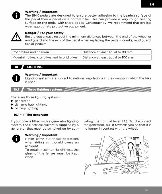
If your bike is fi tted with a generator lighting system, the electrical current is supplied by a generator that must be switched on by acti-
vating the control lever (A). To disconnect the generator, pull it towards you so that it is no longer in contact with the wheel.
10.1 Three lighting systems
Warning / ImportantThe BMX pedals are designed to ensure better adhesion to the bearing surface of the pedal than a pedal on a normal bike. This can provide a very rough bearing surface on the pedal with sharp edges. Consequently, we recommend that cyclists wear appropriate protective equipment.
Warning / ImportantLighting systems are subject to national regulations in the country in which the bike is used.
Warning / ImportantNever carry out these operations when riding as it could cause an accident.To obtain maximum brightness, the glass of the lenses must be kept clean.
Road bikes and children Distance at least equal to 89 mm
Mountain bikes, city bikes and hybrid bikes Distance at least equal to 100 mm
10.1 - 1: The generator
Danger / For your safety Ensure you always respect the minimum distances between the end of the wheel or mud guard and the axis of the pedal when replacing the pedals, cranks, mud guard, tire or pedals:
67

EN
A dynamo hub is a power generator in the hub of the front wheel. The current is gener-ated by turning the wheel, at which point friction is created between the wheel and the dynamo. It enables powerful lighting at low speeds.
There are also lighting systems that are battery operated. They can be built into a fi xed or removable lighting system. This system has the advantage of not creating
► For the batteries: when the red wear indicator illuminates, replace the batteries: 2 alkaline batteries, 1.5 Volts type LR14. The fi tting direction of the batteries is indicated
Adjust the angle of your headlight so that the center of the beam meets the fl oor 10 meters away.
This warning applies to BMX
friction, and thus loss of performance. On the other hand, its battery life is limited to the lifespan of the batteries.
on the bulb holder and on the inner strip. ► For the bulbs: you must use this type of bulb: 2.4 Volts 0.5 A Type: Krypton.
Warning / ImportantFor your safety, always check that the pegs are compatible with your bike before mounting them.
10.1 - 2: Operating a dynamo hub lighting system
10.1 - 3: Battery lighting
10.2
10.3
Adjusting the front light
Replacing the batteries and bulbs
11 PEG
68

EN
The maximum total permitted weight for the cyclist plus baggage must not exceed the
The total permitted weight for the cyclist and baggage must not exceed the maximum
manufacturer's recommendations, namely:
permitted weight (see table above) minus the weight of the bike.
12
13
MAXIMUM TOTAL PERMITTED WEIGHT
UNMOUNTED ACCESSORIES
Danger / For your safety
► Do not carry passengers.
► Do not carry baggage that will unbalance the bike or reduce visibility.
► Most "city" and "travel" bikes are fi tted with baggage holders. These baggage holders comply with standard ISO 11243 and can carry quite signifi cant loads, follow-ing construction and assembly.The maximum permissible load should not exceed the weight indicated on the baggage holder. Please remember that a loaded baggage holder considerably changes the way you ride.
► It is prohibited to fi t a trailer to the baggage holder.Your bike has been designed and built for use by a single person. Cycleurope shall not be liable where the bike is used simultaneously by several people, or when the baggage holder is overloaded.
Danger / For your safety It is essential to follow the assembly instructions provided with the accessory. It is important to respect the torque tightening values. These accessories must be approved and must respect the laws and traffi c regulations in force and be adapted to the bike. Do not hesitate to consult your Cycleurope retailer.
Type of bike Maximum permitted weight(bike + cyclist + baggage)
Mountain bike 100 kg
Hybrid bike 100 kg
Racing 100 kg
Urban/City 100 kg
Electric bike 120 kg
Young adults, 20’’ 55 kg
Young children, 16’’ 45 kg
Young children, 14’’ 33 kg
BMX Category 1 65 kg
BMX Category 2 100 kg
69

EN
13.1
13.2
Unmounted baggage holder
Child seat
Danger / For your safety Not all bikes are suitable for a baggage holder. Do not hesitate to consult your Cycleurope retailer. Never fi t the baggage holder to the seatpost. Avoid overloading the baggage holder as it could fall off and break the components.
Danger / For your safety Our bikes fi tted with baggage holders are compatible with child seats. However, the type of child seat that can be fi tted on the bike depends on the maximum permitted weight indicated on the baggage holder.For both your safety and that of your passenger, we ask that you respect the following assemblies:
Baggage holder acceptsa maximum load of 25 kg
Baggage holder acceptsa maximum load of 27 kg
Only child seats with an attachment to the saddle tube are permitted.
Option of fi tting a child seat directly to the baggage holder (on the condi-tion that the child seat attachment is compatible with the baggage holder).
The front baggage holder must be fi tted to the fork or front axle. They change the stability of your bike. Always carry out checks before riding on a public road.
70

13.3 Trailer
Danger / For your safety A child seat can signifi cantly change the stability of your bike. It is prohibited to affi x a child seat directly to the seatpost of the bike. Under no circumstances must any part of the child's body or clothing (laces, seat belts, etc.) come into contact with any of the bike's moving parts, as this could injure the child or cause an accident. It is recommended that the child seat is fi tted to bikes equipped with protected mud guards to prevent the child from inserting their feet or hands into the spokes of the bike. The same applies to coil springs under the saddle: it is very important to cover them completely to prevent the child's fi ngers from becoming trapped. Check that the seat complies with EC standard EN 14344.
Danger / For your safety Ensure that the trailer assembly is compatible with your bike. Do not hesitate to consult your Cycleurope retailer. It is also down to the correct assembly of the coupling. A trailer changes the stability of your bike. Always carry out checks before riding on a public road. Always respect the maximum permitted loads. Children under 16 years old are not permitted to ride with a trailer.
EN
71

WARRANTY TERMS AND CONDITIONS
Legal warranty: In accordance with the law, CYCLEUROPE INDUSTRIES is liable for any hidden defects in a product marketed by CYCLEUROPE INDUSTRIES under the terms and conditions of article 1641 and in line with the Civil Code.
Contractual warranty: • DURATION AND CONTENT OF THE WARRANTYCYCLEUROPE INDUSTRIES is liable for the correct manufacture of its Products and agrees to repair or replace the defective part caused by a manufacturing defect or labor defect (except for normal wear on a part). The duration of the warranty as of the date indicated on the purchase invoice is: • 5 years for rigid steel, aluminum, or carbon frames (except toys), • 2 years for mountain bike suspension forks and frames, • 2 years for paint and decorations on frames and forks, • 2 years for collapsible frames, • 2 years for electrical components on electric bikes • On third-party components, the applicable duration is according to the manu-facturer.
The spare part used will either be equivalent to the faulty part or of a newer generation, depending on the evolution of products. Work carried out under the warranty shall not affect the duration of the warranty unless other-wise provided for by law.This warranty is given only to the purchaser whose name is on the purchase invoice and is not transferable.
• CONDITIONS FOR IMPLEMENTING THE WARRANTYHowever, this warranty is only valid if regular maintenance or upkeep at least once a year has been carried out by a professional in accordance with the recommendations of the user manual.To implement the warranty, the purchas-er must contact the retailer or any workshop in the network appointed by CYCLEUROPE INDUSTRIES.Thus, warranty operations can be carried out by the entire CYCLEUROPE INDUSTRIES network, regardless of country or place of purchase.The warranty can only be implemented for bikes which are presented complete, in accordance with the original specifi cations, and accompa-nied by their purchase invoice.
• THE WARRANTY DOES NOT COVER: - Damage caused by improper or defective maintenance and by repairs, alter-ations or replacements of parts on the bike carried out by non-professionals. - Damage caused by negligence, defect or poor maintenance (lubrication, adjust-ments etc., as indicated in the user manual), overloading, even temporary, user inexperience, or poor transport conditions, that are not in accordance with the conditions outlined in the user manual. - Bikes used in competitions. - Rust. - Wear parts, i.e.:Dérailleur cables and casings, cables and brake linings, transmission elements (chainring, sprocket, chain, etc.), tape/pads for handlebars, hydraulic oils and lubricants, rims, brake pads, batteries and light bulbs, tires and inner tubes, saddles. - The development of colors over time. - Damage caused by a supervisory defect or, more generally, failure to comply with the instructions and recommendations given in the user manual.
The warranty and liability of CYCLEUROPE INDUSTRIES is strictly limited to the cost of the part in question and does not cover any direct, indirect, material or immaterial damage.The purchaser undertakes, for their part, to take all necessary precautionary measures to limit its damage as well as those of CYCLEUROPE INDUSTRIES.
The bikes defi ned by CYCLEUROPE as being used for professional use are guaranteed for two years plus labor (except wear parts). The warranty will not apply to bikes in the consumer range that are used for professional purposes.
EN
72