designing a protocol agnostic rule engine for a cross
TRANSCRIPT
OLLI HOLMALA
DESIGNING A PROTOCOL AGNOSTIC RULE ENGINE FOR A CROSS-DOMAIN
SOLUTION
Faculty of Information Technology and Communication
Sciences Master of Science Thesis
05/2019
i
ABSTRACT
Olli Holmala: Designing a Protocol Agnostic Rule Engine for a Cross-Domain Solution Master of Science Thesis Tampere University Software Engineering 05/2019
Data protection is an ever-growing concern for businesses and consumers. Industries are digital-izing their business processes at a rapid rate with business transactions increasingly taking place in the digital domain. Particularly in the context of sensitive information it is critical that information be available only to those whom it concerns. Any information access by unauthorized individuals (i.e. data leakage) can cause irreparable harm to the reputation of the company responsible for safekeeping the leaked information.
Communication between software applications that contain varying degrees of sensitive infor-mation poses additional challenges for data protection. A security level difference between two applications may result in incompatibility, as data from one domain may not be suitable for another domain. In practice, the only manner of enabling communication between the two domains is filtering out transmitted data from the first domain that is inappropriate for the second domain. Manual filtration of data can prove a tedious and persistent undertaking, therefore automation of the filtering process can prove to be an attractive alternative. A cross-domain solution (CDS) is a software application placed between two security domains of differing security levels that auto-mates data leakage prevention.
The purpose of this thesis was to design a protocol agnostic rule engine for a cross-domain solution. A rule engine provides customizability for the filtering logic of the CDS, so that its users can dynamically determine what to filter. As the communicating applications can transmit data using a variety of protocols, the objective was that the rule engine would function in a similar manner regardless of the chosen protocol.
The design of the engine was based on the architecture of existing business rule engines. Comparing the existing rule engines revealed their commonalities, differences and best practices. These practices were then customized and applied to the rule engine of this thesis.
Additionally, the input and output of the CDS was demonstrated with two example protocols that the CDS supports: ASTERIX and the HLA. The structure of both protocols was examined in order to provide a better understanding of the type of data the CDS processes. Furthermore, comparison of similarities and differences revealed the challenges with achieving protocol agnos-ticism.
The rule engine was designed using the C4 model for architecture design. Architecture was illustrated with diagrams at multiple levels of abstraction, beginning at the system context level and ending with the component level. The design was constrained by a set of both business and regulatory requirements, which the resulting implementation adequately fulfilled. Ultimately, the resulting implementation was able to perform filtering operations on both example protocols in a protocol agnostic manner.
Keywords: cross-domain solution, rule engine, protocol agnosticism The originality of this thesis has been checked using the Turnitin OriginalityCheck service.

PREFACE
Writing this thesis has been one the greatest challenges of my university career. Balanc-
ing my time between work and thesis writing was not always easy but thankfully I was
able to manage it with a regular writing schedule and with the help of my supervisors.
I feel like I have learned a lot during my thesis writing process, both on the context of the
thesis and academic writing in general. In the fall of 2018, I was mostly ignorant on the
topics of this thesis. Now I am more informed, yet the learning process continues, as
there is still much to learn.
I would like to thank Marko Latvala for his guidance during the thesis writing process and
for steering me in the right direction whenever I attempted to veer out of scope. Marko
helped me keep to the agreed upon schedule and was patient with me whenever I fal-
tered. Additionally, I want to thank prof. Kari Systä for helping me mold the text into an
academic format and for devoting so much of his time to instructing me in my thesis
writing. Whenever I needed help, Kari was always there to provide it, and for that I am
thankful. Finally, I would like to thank my family and friends for their support.
Tampere, 2 May 2019
Olli Holmala

CONTENTS
1. INTRODUCTION .................................................................................................. 1 2. CROSS-DOMAIN SOLUTION ............................................................................... 4
2.1 Conceptual Overview ........................................................................... 4
2.2 Security Models and Practices ............................................................. 6
2.2.1 OSI model ..................................................................................... 6
2.2.2 Defense-in-depth .......................................................................... 8
2.2.3 Bell-LaPadula model ..................................................................... 8
2.2.4 Biba model .................................................................................... 9
2.3 Finnish Regulatory Guidelines ........................................................... 10
2.3.1 Unidirectional solutions ............................................................... 11
2.3.2 Content filtering solutions ............................................................ 12
2.3.3 Other solutions ............................................................................ 13
3. RULE ENGINES ................................................................................................. 14 3.1 What is a Rule Engine? ...................................................................... 14
3.2 Purpose of Rule Engines ................................................................... 16
3.3 Implementations of Business Rule Engines ....................................... 17
3.3.1 Drools ......................................................................................... 17
3.3.2 Jess ............................................................................................ 18
3.3.3 Easy Rules.................................................................................. 19
3.4 Evaluation of Rule Engines and Rule Syntax ..................................... 19
4. COMMUNICATION PROTOCOLS ...................................................................... 21 4.1 ASTERIX ........................................................................................... 21
4.2 HLA .................................................................................................... 24
4.3 Comparison of Chosen Protocols ....................................................... 26
5. ARCHITECTURE OF THE SOLUTION ............................................................... 28 5.1 Requirements..................................................................................... 28
5.2 Context .............................................................................................. 30
5.3 Containers ......................................................................................... 31
5.4 Components ...................................................................................... 35
6. RESULTS AND CONSTRAINTS......................................................................... 41 6.1 Evaluation of Rule Engine Implementation ......................................... 41
6.1.1 Meeting Business Requirements ................................................. 41
6.1.2 Application of Security Models .................................................... 42
6.1.3 Fulfilling TRAFICOM guidelines .................................................. 42
6.1.4 Protocol Agnosticism .................................................................. 43
6.1.5 The Rule Engine in Practice ........................................................ 43
6.2 Constraints of the Rule Engine ........................................................... 44
7. CONCLUSIONS .................................................................................................. 46 REFERENCES....................................................................................................... 47
LIST OF SYMBOLS AND ABBREVIATIONS
ADCCP Advanced Data Communication Control Protocol AMG ASTERIX Maintenance Group API Application Programming Interface ASTERIX All-purpose structured EUROCONTROL surveillance information
exchange CAT Data Category CDS Cross-Domain Solution DIS Distributed Interactive Simulation DoS Denial of Service DRL Drools Rule Language DSL Digital Subscriber Line FOM Federation Object model FSPEC Field Specification FTP File Transfer Protocol FX Field Extension HDLC High-Level Data Link Control HLA Higher-Level Architecture HTTP Hypertext Transfer Protocol I/O Input-output IDE Integrated Development Environment IEEE Institute of Electrical and Electronics Engineers IP Internet Protocol ISDN Integrated Services Digital Network JSR Java Specification Request KIE Knowledge Is Everything KVM Keyboard, Video Monitor and Mouse LEN Length Indicator LHS Left hand side MAC Mandatory Access Control MLS Multi-level solution MPEG Moving Picture Experts Group MVEL MVFLEX Expression Language NAT Network Address Translation NetBIOS Net Basic Input/Output System OMT Object Model Template OS Operating System OSI Open Systems Interconnection POJO Plain Old Java Object PPP Point-to-Point Protocol REP Field Repetition Indicator RPR Real-time Platform-level Reference RTI Run-time Infrastructure SAC System Area Code SIC System Identification Code SISO Simulation Interoperability Standards Organization SMTP Simple Mail Transfer Protocol SOM Simulation Object Model ST Suojaustaso SQL Standard Query Language TCP Transmission Control Protocol TRAFICOM Finnish Transport and Communications Agency UAP User Application Profile

UDP User Datagram Protocol USB Universal Serial Bus XML Extensible Markup Language YAML YAML Ain’t Markup Language
1
1. INTRODUCTION
One of the most persistent problems of our time is the protection of sensitive information
from unwanted observers, a phenomenon conceptually known as information security.
Techniques for protecting information are numerous and commonly focus on protecting
data content, e.g. by cryptographic means, or on restricting access to the data itself. In
the latter approach, information is grouped by sensitivity level, which is a metric of the
potential for harm should the information be exposed to hostile or malicious parties. Sen-
sitive information is often assigned a classification or security level, which determines
who may access and manipulate that information.
When it comes to particularly sensitive information, such as classified military infor-
mation, data transfer between organizations requires a plethora of safety precautions to
protect from intruders. It is common practice to separate classified data from unauthor-
ized viewers by safeguarding it in a security domain. Traditionally a security domain has
meant a physically isolated space, such as a locked or guarded room. In the digital age
however, security domains have moved to the virtual space, and are often restricted to
computer networks of varying degrees of isolation. Similar to its traditional implementa-
tion, a virtual security domain (e.g. a single computer network) is assigned a security
level. In military organizations, the security level is determined by the classification level
of the domain. Nevertheless, security and classification domains are not merely re-
stricted to militaries, as government organizations and even corporations also utilize
them in the protection of private information and trade secrets.
Providing that the proper precautions have been taken, storing data in an isolated
security domain can prove a relatively secure solution. Nonetheless, the utility of data
that is restricted to a single domain is limited. Thus, it is paramount that data be able to
move between domains. Cross-domain data transfer poses its own set of challenges. As
domains can belong to differing security levels, the party responsible for data transfer
must be able to reliably prevent the leakage of restricted data from one domain to an-
other. In order for two organizations of differing classification levels to interact with one
another, information must be filtered so that data from the higher-level domain is stripped
of information unsuitable for the lower domain. Moreover, data must be validated to en-
sure that malicious or otherwise malformed data does not reach either domain. These
tasks are the central responsibilities of a cross-domain solution (CDS).
A cross-domain solution is a component placed between two domains. All traffic
passes through the cross-domain solution. Ideally, the CDS ensures that data confiden-
tiality and data integrity are not compromised. In addition to acting as a filter for data
traffic, a CDS also has the potential to mutate the content of messages. Most commonly
this functionality is used to strip confidential information from forwarded messages. Mu-
tability also has implications for completely disassembling and reassembling the mes-
sage itself or even for adding new information. Depending on a message’s structure,
2
mutation functionality can have a vast array of applications, which can be entirely de-
pendent on the context within which the CDS operates.
To combat the potential for variability of both message content and program flow, a
rule engine will be introduced into the CDS. The purpose of this thesis is to attempt to
implement a rule engine software component into the cross-domain solution. The rule
engine will empower users of the CDS with the ability to configure filtering logic to their
specific needs. Users can be expected to operate in various contexts and therefore utilize
a multitude of different communication protocols. Consequently, the rule engine’s imple-
mentation must be generic, so that it functions irrespective of communication protocol.
By ensuring that the rule engine is protocol agnostic, more supported protocols can eas-
ily be added to the CDS, leading to more potential users and thus better scalability.
In addition to protocol agnostic functionality, the engine must adhere to Finnish regu-
latory guidelines for CDSs, as well as business requirements set for the rule engine.
While the regulatory guidelines focus on information security, the business requirements
determine how the rule engine should operate. The objective of the rule engine design
of this thesis is to fulfill primary regulatory and business requirements, as well as achieve
protocol agnosticism.
Initial protocol agnostic functionality for the rule engine requires support for two proto-
cols supported already by the CDS. The first is the High-Level Architecture (HLA), a
protocol for communication of distributed simulation data. The second implemented pro-
tocol is the All Purpose Structured Eurocontrol Surveillance Information Exchange,
known as ASTERIX, a protocol used by the aviation industry.
As the focus of this thesis is the rule engine component, the scope will be limited to
its functionality. Any supporting components will be described at a level that provides the
necessary context for the rule engine but will otherwise be regarded as outside of scope.
Pertaining to the rule engine, the thesis will strive to answer the following research ques-
tions:
How should the rule engine be designed in light of the business requirements and
regulatory guidelines?
How can the commonalities of the supported protocols be leveraged to achieve
protocol agnosticism for the rule engine?
What are the best practices of rule engines that should be applied in the design
of this thesis?
Given the set of research questions, the structure of this thesis is the following. Firstly,
the cross-domain solution will be defined at a conceptual level to provide an understand-
ing on its purpose, its potential implementations and its requirements. The conceptual
overview will be complemented with supporting theoretical models from the literature, to
provide a rudimentary understanding of the security and network principles the solution
should adhere to. This will be followed by an outline of the guidelines imposed by the
Finnish Transport and Communications Agency (TRAFICOM), which are based on the
models provided in its preceding chapter.
Once the theoretical background and regulatory guidelines have been established, an
introduction to the literature for rule engines will be presented, along with the problems
associated with creating a generic rule engine. Following the section on rule engines,

3
the structure of both ASTERIX and HLA will be expounded upon, as they will be utilized
in assessing the generalizing capabilities of the final product. Both protocols additionally
serve as examples of the type of content the CDS will be required to process.
Finally, the protocol comparison will be succeeded by the requirements of the archi-
tecture design along with a description of the design itself. After the architecture design,
the resulting product is analyzed to determine how well it fulfills its central responsibilities.
The conclusion will recount how well the project succeeded and provide a brief glimpse
into its future.
Implementation effort and scope will be constrained by the deadlines of the CDS soft-
ware project. The project itself is being implemented for and funded by Insta DefSec Oy
and the writer of this thesis is an employee in the CDS software team.

4
2. CROSS-DOMAIN SOLUTION
This chapter outlines the characteristics of a cross-domain solution. The purpose of this
chapter is to introduce cross-domain solutions along with the guidelines placed for them
by Finnish authorities. The following conceptual overview provides a general introduction
to cross-domain solutions by describing their architecture and by providing example im-
plementations. The conceptual overview is followed by several models that function as
the theoretical background for the regulatory guidelines of the cross-domain solution.
Finally, the chapter closes with a description of the guidelines set by the Finnish
Transport and Communications Agency, which introduce the regulatory requirements for
the solution.
2.1 Conceptual Overview
The primary purpose of a cross-domain solution is to enable the secure transfer of infor-
mation between two domains of differing classification or security levels. A typical appli-
cation of CDS involves data transfer between a higher level of security clearance to a
domain of lower clearance. Although, it is often applied across military domains, a CDS
has applications in security sensitive industries. In this thesis, the rule engine will be
designed for both military and civilian applications, where data is transferred between
domains of differing classification or security level. Any references to multiple security
domains in this thesis will implicitly assume that they are of differing security or classifi-
cation level.
Figure 1. Architecture of a cross-domain solution.
The techniques for implementing a CDS are numerous and can be evaluated from mul-
tiple perspectives. For example, Smith (2015) groups cross-domain solutions into three
types: Access, Transfer and Multi-level. The distinction between the implementations
comes from the restrictions placed on data flow between domains.
An access solution allows for “read-only” access to data between two domains. Data
flow between domains is restricted to ensure that data does not “leak” outside of its do-
main. In addition, data between domains is intended to ideally be as mutually exclusive

5
as possible, although in practice mutual exclusivity is almost unattainable. Access solu-
tions can rely on different forms of hardware segmentation of security domains to com-
plement software safeguards.
Hardware segmentation can, for example, be implemented with techniques such as
Keyboard, Video monitor and Mouse (KVM) switching or periods processing. With KVM
switching, the user is able to access multiple security domains, although one at a time.
The keyboard, monitor and mouse of the user are attached to a KVM switch, which can
be linked to a single computer at a time. Computers are connected to one security do-
main at a time, therefore whenever the user switches computers, he also switches do-
mains. The less common periods processing method is a time-based solution, whereby
the security domain (i.e. the network) periodically shifts classification level at regular in-
tervals. Before a classification shift occurs, all data in the domain is sanitized for com-
patibility with the new classification level.
Moreover, hardware segmentation can be simulated via virtualization techniques, in
which one virtualized domain interacts with another virtual or physical domain. Virtual
machines running on a physical machine can belong to a lower classification level than
the host machine, even though the machine’s operator may be able to access both do-
mains.
Transfer solutions permit the transfer of data from one domain to another. The chal-
lenge with allowing data transfer is respecting the classification level of the data itself, so
that data transfer from high to low classification does not result in leakage of classified
material. Data transfer can also be limited by the direction of data flow, as a solution can
be either unidirectional or bidirectional. Unidirectional data transfer provides better secu-
rity for the system, whereas bidirectionality enables better flexibility between domains. In
practice, transfer solutions range from a simple air gap solution, in which data is trans-
ferred via USB-media, to a data diode (see section 2.3.1 below), where data is trans-
ferred via a connection that is unidirectional at the physical layer (e.g. via a unidirectional
fiber-optic cable). Transfer solution implementations vary in their level of automation,
both in terms of transfer itself, in addition to any data validation.
A multi-level solution (MLS), according to Smith, essentially solves the need for CDS.
Instead of having multiple single layer systems, each in its own security domain and
interacting with one another, Smith suggests the correct course of action is to unify the
systems into one security domain. The premise is that “[t]he solution uses trusted label-
ing and integrated Mandatory Access Control (MAC) schema to parse data according to
user credentials and clearance in order to authenticate read and right privileges”, thereby
eliminating the need for cross-domain solutions between systems. However, even Smith
admits that, although the solution would be ideal, it may prove too expensive to imple-
ment in practice.
A majority of cross-domain solutions are access or transfer solutions. As security do-
mains may not necessarily even belong to the same organization, an MLS under one
single domain can be considered impractical. The CDS of this thesis will be required to
operate as a separate component between software programs of differing classification
level and communication protocol, therefore the solution will be a transfer solution. From
an architectural perspective, the focus will be on the bidirectional guard.

6
Figure 2. A bidirectional and unidirectional CDS.
A bidirectional guard consists of a server, placed between two domains and connected
to both domains by two data diodes each. The guard’s task is to perform content inspec-
tion on all data flow to and from any one domain. This ensures that the data entering
either domain has undergone data validation and data filtration. The unidirectionality of
data diodes hinders attempts by potential attackers in retrieving data from a classified
domain.
The guard itself, placed between the domains, contains the business logic of the so-
lution itself. The main responsibilities it fulfills are:
Data validation
Data filtration
Logging of activity
In data validation, the integrity of the data is verified, to assure that structure of the
data is acceptable. Data filtration on the other hand is one of the most central functions
of a CDS, as it prevents sensitive data from reaching unrestricted or unauthorized secu-
rity domains. Filtration can include the partial manipulation of data, such that only por-
tions of data are removed or manipulated to allow for lower classification levels. Finally,
data traffic and other activity logging ensures accountability of the system and traceability
of errors.
2.2 Security Models and Practices
The requirements of the CDS will be based on several key security and networking con-
cepts that must be adhered to and understood in order to provide a secure solution.
Furthermore, these models are referenced in the relevant documentation on CDSs and
their regulation in Finland.
2.2.1 OSI model
The Open Systems Interconnection (OSI) model is a high-level model for conceptualizing
network layers. The model is divided into seven layers, beginning with the lowest layer,

7
the physical layer, and ending with the application layer (Briscoe 2000). Implementations
of many security models must often be applied on multiple network layers. Additionally,
the Finnish regulatory guidelines set for CDSs reference the OSI model several times.
Figure 3. The Open Systems Interconnection model.
Layer 1: The physical layer is the lowest layer in the model, consisting of the physical
devices that are responsible for data input-output (I/O) of a system in the network. The
responsibilities of devices belonging to the physical layer include the reception of un-
structured raw data, conversion of that data for use at higher layers, and transmission of
data.
Layer 2: The data link layer consists of the linkages between nodes in a network. The
main responsibility of the layer is allocation of the physical media for transfer of data. For
example, protocols such as PPP, HDLC and ADCCP all belong to the data link layer.
Layer 3: Known as the network layer, layer three enables data to flow in the network.
Its main function is packet forwarding and routing between nodes in the network. The
most prominent example belonging to layer three is the Internet Protocol (IP).
Layer 4: Also known as the transport layer, this layer hosts the functions used for
transferring data across the network. While the network layer is responsible for the main-
taining of connections on a network, the transport layer is responsible quality of service
problems such as flow control, segmentation and error control. The most common ex-
amples of transport layer protocols are the Transmission Control Protocol (TCP) and
User Datagram Protocol (UDP).
Layer 5: The session layer controls connections between two nodes. Its main respon-
sibilities include the opening and closing of sessions and other management tasks and
the layer permits full-duplex, half-duplex and simplex operations.

8
Layer 6: The presentation layer processes data as it arrives from the network into a
format that is usable for applications. Typical tasks assigned to the presentation layer
are encryption, compression and, most importantly, serialization.
Layer 7: The final layer, known as the application layer, is the end-user facing layer.
It includes protocols such as the File Transfer Protocol (FTP) and Simple Mail Transfer
Protocol (SMTP).
Understanding the OSI model is critical in order to understand the requirements for
secure data transfer. Furthermore, the concept of OSI model is central to many common
security policies built around defense-in-depth, which relies on a layered architecture.
The rule engine of this thesis will be an application layer implementation.
2.2.2 Defense-in-depth
Defense-in-depth is a security model for protecting critical infrastructure such as nuclear
reactors (USNRC 2018) or central resources in information technology systems (R. Lipp-
mann et al. 2006). The premise of defense-in-depth is that the best level of security is
achieved by layering or segmenting security on multiple levels so that a breach in one
level does not result in a breach of the entire system. A defense-in-depth security strat-
egy therefore relies on a multi-layer architecture within the same security domain. (Kui-
pers, Fabro 2006)
In practice, defense-in-depth can, for example, mean defenses at the physical level,
such as fences or guard patrols on the premises, which can be further complimented
with barriers preventing access to the system itself (e.g. smart cards, hard-disk encryp-
tion, etc.) at an application level. Penetration of the physical level does not grant access
of data to the attacker, as they must further penetrate the safeguards placed at the ap-
plication level. However, the method is often regarded as a technique for slowing attack-
ers down, therefore requiring complimentary safety measures to assure robust security
for the system.
2.2.3 Bell-LaPadula model
The Bell-LaPadula model is a formal security model developed for the United States’
Department of Defense that models multilevel security access control policy using state
machines. Bell and LaPadula intended for the model to be operating system independ-
ent. The model focuses on enforcing data confidentiality levels by attempting to prevent
unauthorized access to classified data.
Conceptually the model consists of “subjects” and “objects”. Subjects are general rep-
resentations of active parties such as individuals or software processes, whereas objects
represent passive software artifacts (e.g. documents, registries, etc.). Subjects access-
ing objects require compliance with a security policy, in order to maintain a secure state
of the system. The main purpose of the model is to prevent unauthorized access (read,
write or execute) of objects by subjects.
Each subject and object is given a confidentiality level on a scale typically ranging
from Low to High. Object confidentiality level is determined based on the effect on the
organization, should the data content of the object be exposed to unwanted actors (i.e.
9
leak). Consequently, the subject confidentiality level determines which content the sub-
ject is permitted to access. A Low confidentiality level signifies minor impact in the event
of data leakage, whereas High indicates substantial impact on the organization. (Taylor,
Shepherd 2007)
Interactions between subject-object pairs are determined according to a set of prop-
erties based on their confidentiality levels:
1. The Simple Security Property
o Subjects may not read objects with a higher confidentiality level
2. The *-Property (Star property)
o Subjects may not write to an object at a lower security confidentiality level
3. The Discretionary Security Property
o Discretionary access control is outlined in an access matrix
The three properties, and the Bell-LaPadula model itself, are often summarized as
“read down, write up” access control. Under a system that respects the model of access
control, a user cannot read any data of a higher confidentiality level than themselves, as
doing so would result in a breach of data confidentiality. Conversely, writing can only
occur in the opposite direction, as any writes downward have the potential for data leak-
age. Permitting downward writes relies on the user being able to independently enforce
confidentiality rules, leading to a persistent risk of data leakage. Thus, the Bell-LaPadula
model surmises that it is safer to remove the option of downward writes altogether.
2.2.4 Biba model
The Biba model is a response to the Bell-LaPadula model that emphasizes data integrity
by building on the concepts developed by Bell and LaPadula. While the Bell-LaPadula
model focuses on mandatory policy and confidentiality, the Biba model seeks to further
strengthen security policy by grouping subjects and objects with an integrity level. (Estes
2011)
Data integrity differs from data confidentiality in that where data confidentiality deter-
mines who can access the data; data integrity determines how data can be manipulated.
Data integrity policy attempts to particularly minimize changes to data, so that it remains
meaningful, logical and consistent between its different states. (Sandhu 1993)
The traditional method for determining a data integrity level for objects is similar to the
method for selecting confidentiality level. The content of the object is assessed and given
a level on a scale according to the resulting harm to the organization should the content
of the object be manipulated in an unwanted manner. Much like confidentiality level, in-
tegrity levels are usually a variation of the Low-Medium-High scale where a Low integrity
level indicates low impact and High indicates a detrimental level of impact. (Taylor, Shep-
herd 2007)
Like its predecessor, the Biba model proposes three properties (Biba 1977) for data
integrity in its strict integrity policy:
The Simple Integrity property
o subjects may not observe objects of lower integrity level than themselves
The *-Integrity property (Star Integrity Property)

10
o subjects may not modify objects of higher integrity level
The Invocation property
o subjects may not invoke subjects of higher integrity level
The terms observe, modify and invoke are analogous to read, write and execute, re-
spectively. The model is characterized as the opposite or inverse of the Bell-LaPadula
model, i.e. as “read up, write down” (Bishop 2003). As the model focuses on data integ-
rity, it restricts mainly the manipulation of data. The premise of the model is that data
integrity remains intact when data only flows downward in the integrity level hierarchy.
Any one user cannot manipulate objects with a higher integrity level than themselves,
whereas they are able to read data above their integrity level. Therefore, any data moving
down the hierarchy cannot be manipulated, and integrity remains intact.
When coupled with the Bell-LaPadula model, subjects are permitted access only to
objects within the same level (assuming that integrity and classification level are the
same), leading to an inflexible security policy. Practical solutions require compromises,
in order for the security policy to support multi-level solutions.
2.3 Finnish Regulatory Guidelines
The Finnish Transport and Communications Agency (TRAFICOM) oversees regulation
and oversight of communications in Finland and therefore determines acceptable stand-
ards for transfer of sensitive information in government organizations. In the case of
CDSs, TRAFICOM has a purpose-built guide containing acceptance criteria for a secure
solution (FICORA 2016). In this section, TRAFICOM will be referred to as the “regulatory
authority”.
As stated in the guide, the central goal of an acceptable CDS is the realization of the
Bell-LaPadula model’s “no read up, no write down” policy, so that data of a higher clas-
sification never moves to a domain of lower classification. The choice of security model
(versus e.g. the Biba model) indicates an emphasis on data confidentiality, which is pre-
dictable considering the solution’s intended use cases in sensitive government contexts.
Although the Bell-LaPadula and Biba models are not mutually exclusive in theory, they
result in an impractically strict security policy when used in the same domain. The result-
ing model restricts read and write access to the same security level of the accessor (often
called the “Strong Star Policy”), completely eliminating vertical access of data (Sandhu
1994).
The regulatory authority recognizes multiple types of implementations that fulfill its
criteria. These implementations are categorized as either:
Unidirectional filtering solutions that prevent any data flow from a higher domain
to a lower one or
Content filtering solutions that strip sensitive data belonging to a higher domain,
when transferring to a lower domain.
Other cited criteria for acceptance include the concepts of defense-in-depth, fail safety
and adhering to the principle of least privilege.
11
In addition to providing the recommended security models for a CDS, the guide also
outlines several practical guidelines for its implementation. For instance, any data trans-
fer between two domains of different classification level must comply with the security
policy of the higher (i.e. more sensitive) classification level. The system itself must be
robust against threats from its environment (e.g. the operating system). Furthermore, the
system’s reliability must also be available for scrutiny via security audits conducted by
the regulatory authority or its chosen representative.
The guide provides several characteristics for acceptable implementations of a CDS,
which are categorized into unidirectional solutions, content filtering solutions and other
solutions.
2.3.1 Unidirectional solutions
In terms of complexity, unidirectional solutions are the simplest solutions presented in
the guide, as is shown by the most common unidirectional implementation, the data di-
ode. Intrinsically a data diode restricts data flow to one direction in the physical layer of
the OSI model, thereby setting constraints on the architecture of the CDS. A typical so-
lution could include two hardened servers connected via a UDP diode with data integrity
verification on both ends.
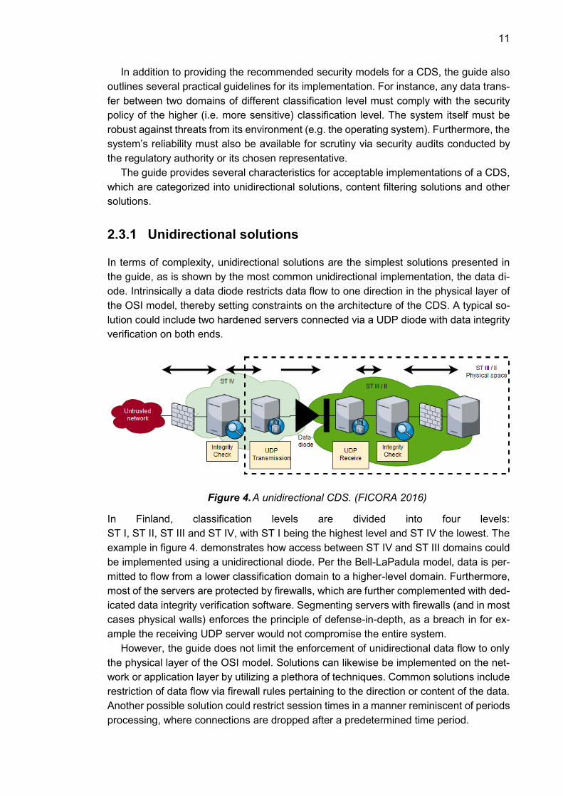
Figure 4. A unidirectional CDS. (FICORA 2016)
In Finland, classification levels are divided into four levels:
ST I, ST II, ST III and ST IV, with ST I being the highest level and ST IV the lowest. The
example in figure 4. demonstrates how access between ST IV and ST III domains could
be implemented using a unidirectional diode. Per the Bell-LaPadula model, data is per-
mitted to flow from a lower classification domain to a higher-level domain. Furthermore,
most of the servers are protected by firewalls, which are further complemented with ded-
icated data integrity verification software. Segmenting servers with firewalls (and in most
cases physical walls) enforces the principle of defense-in-depth, as a breach in for ex-
ample the receiving UDP server would not compromise the entire system.
However, the guide does not limit the enforcement of unidirectional data flow to only
the physical layer of the OSI model. Solutions can likewise be implemented on the net-
work or application layer by utilizing a plethora of techniques. Common solutions include
restriction of data flow via firewall rules pertaining to the direction or content of the data.
Another possible solution could restrict session times in a manner reminiscent of periods
processing, where connections are dropped after a predetermined time period.

12
2.3.2 Content filtering solutions
While unidirectional solutions specialize in data transfer from a lower-level domain to a
higher-level domain, content filtering solutions are capable of data flow in the reverse
direction. Content filtering solutions permit data transfer from a higher security domain
to a lower one and, naturally, transfer between domains of the same classification level.
The regulatory authority sets constraints on the content being filtered in addition to
the quality of the filtering itself with the following rule set:
Data must be recognizable and correctly identified
Application level message structure must be specifically defined
Compliance with defined message structure must be verified
Application level filtering functions correctly regardless of the correctness of input
Filtering functionality must be separate from other application functionality
Filtering functionality must minimize vulnerability potential and filtering must be
implemented on multiple layers
In practice, adequate content filtering requires implementations on multiple layers of
the OSI model. At the network layer, data flow can be restricted through port restrictions,
whereas application layer filtering requires sanitization checking on the messages them-
selves. Typical sanitization includes verification of message length and syntax against
known message structure. The regulatory authority outlines that particularly application
layer implementations are required to be accountable for their correct functionality.
In terms of Finnish classification levels, content filtering permits bidirectional data
transfer between ST IV and ST III. However, coupling content filtering with a data diode
permits data transfer from even ST II domains to ST IV.
Figure 5. Content filtering and diode solution. (FICORA 2016)
The figure above illustrates an example for combining a content filtering solution with a
data diode. Similar to figure 4. the solution features a diode that separates two classifi-
cation domains, although the direction of the diode is reversed. Moreover, the servers in
the ST III/II domain fulfill content filtering and logging tasks in addition to data integrity
verification.
13
2.3.3 Other solutions
Finally, the authority recognizes several implementations that do not meet acceptance
criteria for a CDS but are suitable as alternate solutions in the case of irregular circum-
stances (e.g. due to physical space constraints). Provided example implementations in
the guide include traffic flow filtering, thin or zero client clients, multi-layer solutions, vir-
tualization, and KVM solutions.
Traffic flow filtering is similar to content filtering with respect to its data flow permis-
sions (lower-to-higher, higher-to-lower, across). However, instead of filtering the content
itself, the data traffic is filtered by preventing unwanted traffic flow and permitting legal
traffic. In practice this commonly includes checks for protocol compliance at the network
layer in addition to IP port restrictions. Traffic flow filtering is often coupled with content
filtering to provide comprehensive filtering functionality.
The guide’s example of a virtualization solution is similar to Smith’s (2015) segmen-
tation through virtualization technique. The authority suggests that the physical host com-
puter belonging to a higher classification level can receive data from a virtual machine
belonging to a lower classification domain. Data transfer conventions adhere to the
higher classification level’s security policy and all sessions must be initiated by the host
machine. This type of solution includes implementations such as a web interface or mail
server.
KVM solutions prevent data transfer from one domain to the other by forbidding sim-
ultaneous KVM connections to two or more domains. By itself a KVM solution does little
to restrict unauthorized data transfer, and as such is often used as a complementary
technique for segmenting domains.
Thin or zero client architectures enable the use of multiple domains from one com-
puter. The solution is similar to period’s processing, as it relies on the computer being
reinitialized at the beginning of every session and memory being erased after use. The
accessing computer is required to have security policy according to the highest classifi-
cation it has access to. The direction of data flow between domains of differing classifi-
cation is unrestricted for this technique (low-to-high, high-to-low and across all permit-
ted), although up to a maximum of ST III classification.
Finally, the regulatory authority recognizes what it calls “multi-layer solutions”, which
are essentially partitioned workstations (Smith 2015). Domains reside on the same phys-
ical machine but are segmented by a combination of software (i.e. virtualization) and
hardware techniques. A fully software reliant solution is in essence a virtualization solu-
tion, which can include a hardened OS running on multiple virtual machines of differing
classification level. Conversely, fully hardware-oriented solutions simply separate the
hardware components of two physical machines of different security domains, even
though they both reside within the same physical casing. Generally, the only common
component to the domains will be a monitor.
The objective of this thesis is to design a rule engine for the CDS that will fulfill content
filtering and inspection duties. A rule engine has the potential to meet TRAFICOM re-
quirements in addition to providing dynamic customizability of filtering logic for users.
First however, the concept of rule engines must be introduced.
14
3. RULE ENGINES
This chapter provides an introduction into rule engines, followed by their common use
cases. Although several of the provided examples are not explicitly intended for cross-
domain solutions, their design principles can be utilized in the rule engine of this thesis.
3.1 What is a Rule Engine?
In general, the purpose of rule engines is to provide capabilities for non-technical users
to manipulate business logic of the system. Rule engines are often called business rule
engines, as the rules generally entail additional business logic for the system without the
need to modify source code.
The origin of rule engines is rooted in the 1970s with the advent of expert systems
(Feinstein 1989). Expert systems attempt to replicate or emulate human expertise and
were originally invented by artificial intelligence researchers (Jackson 1990) . An expert
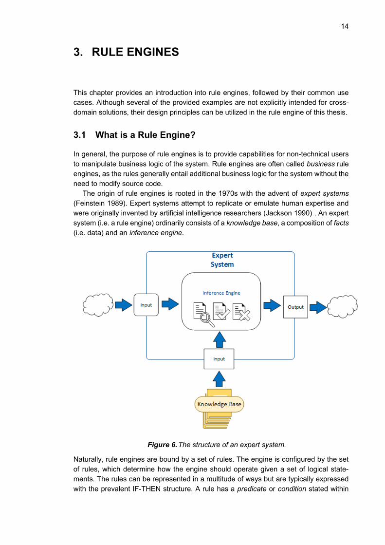
system (i.e. a rule engine) ordinarily consists of a knowledge base, a composition of facts
(i.e. data) and an inference engine.
Figure 6. The structure of an expert system.
Naturally, rule engines are bound by a set of rules. The engine is configured by the set
of rules, which determine how the engine should operate given a set of logical state-
ments. The rules can be represented in a multitude of ways but are typically expressed
with the prevalent IF-THEN structure. A rule has a predicate or condition stated within

15
an if-clause, which upon fulfillment leads to an action or operation, characterized by a
then-clause.
The rule set is fed to a rule or inference engine, a component that is responsible for
execution of the operating logic of the expert system. The set of rules form the knowledge
base of the system.
After completing configuration of the rule set and any further initialization processes,
the system is ready to receive input. A single unit of operable data is called a fact, and
the total set of facts form the knowledge base of the system.
The rule engine may operate on the knowledge base perpetually, triggering opera-
tions as the states of facts are mutated by the application. Alternatively, it may function
as an input-output system where facts trigger rules once they are fed to the system and
are passed onward after all rules have been processed a single time. The operations
can operate on the facts themselves (i.e. the data) or have external side effects on the
application.
From a procedural perspective, rules are commonly executed with either forward
chaining or backward chaining. Forward chaining is a logical process that begins with
the allotted data input and terminates the end-result or goal, whereas backward chaining
is the same process in reverse. Formally, both techniques observe the logical inference
rule of modus ponens, which is characterized by the chained IF-THEN structure (Britan-
nica Academic 2019).
Both chaining techniques can be demonstrated with a simple example. Suppose that
a forward chaining inference engine is given the following knowledge base consisting of
four rules:
1. 𝐼𝑓 𝑥 ∈ 𝐴 𝑎𝑛𝑑 𝑥 ∈ 𝐵 → 𝑇ℎ𝑒𝑛 𝑥 ∈ 𝐶
2. 𝐼𝑓 𝑥 ∈ 𝐶 𝑎𝑛𝑑 𝑥 ∈ 𝐷 → 𝑇ℎ𝑒𝑛 𝑥 ∈ 𝐸
3. 𝐼𝑓 𝑥 ∈ 𝐸 → 𝑇ℎ𝑒𝑛 𝑥 ∈ 𝐹
4. 𝐼𝑓 𝑥 ∈ 𝐼 𝑎𝑛𝑑 𝑥 ∈ 𝐽 → 𝑇ℎ𝑒𝑛 𝑥 ∈ 𝐾
After initialization of the knowledge base into the inference engine, the system is given
two facts:
𝑥 ∈ 𝐶
𝑥 ∈ 𝐷
As the two facts fulfill the antecedent (i.e. the if-clause) of the second rule in the
knowledge base, the engine infers a new fact 𝑥 ∈ 𝐸 based on the consequent (i.e. the
then-statement). The new fact is added to the knowledge base, leading to further chain-
ing.
The new fact is substituted in the antecedent of the third rule, resulting in yet another
fact:
𝑥 ∈ 𝐹
This is the conclusion and output of the forward chaining process, as the result does
not satisfy any further rules.
16
Backward chaining would begin where forward chaining concluded. The goal in a
backward chaining context would be to prove 𝑥 ∈ 𝐹 by matching the goal to consequents,
instead of antecedents, in the knowledge base. After matching to a consequent, the
matched rule’s antecedent becomes the new goal to prove. If the original goal is true,
the backward chaining process should lead to the facts initially provided in the knowledge
base (i.e. 𝑥 ∈ 𝐶 𝑎𝑛𝑑 𝑥 ∈ 𝐷).
Using these simple mechanisms, a rule engine can perform a multitude of tasks. De-
pending on the use case, the engine can be extended with further decision logic such as
non-discrete truth-values (i.e. fuzzy logic) or more Boolean operators (e.g. AND, OR) for
rules’ antecedents, etc. However, for the purposes of this thesis rule scope will be limited
to the simple IF-THEN structure, as it enables sufficient pattern matching and conditional
logic capabilities.
3.2 Purpose of Rule Engines
A traditional software application requires a software development process for the addi-
tion of new business logic via more implemented software features. This traditional pro-
cess always involves software developers, who work to make the desired features a
reality. A simple business rule such as “if a customer has our loyalty card, then they are
entitled to a 5% discount”, may require a comparatively large time investment to reach
the production environment of the application. Especially when a rule is time constrained,
the system does not provide the means for rapid changes in business logic.
Business rule engines seek to remedy this dilemma. A rule engine enables modifica-
tion and addition of rules, ideally at runtime. As such, the system’s business logic can be
shaped to the needs of the current moment in a swift manner. Furthermore, the process
is no longer tied to software developers. The persons responsible for modifications to
business logic are free to alter it by themselves.
In his book on building business rule engines, Chrisholm (2004) provides several ex-
amples of the typical users of rule engines. Users vary in their level of technical profi-
ciency and knowledge of business processes. For example, Chrisholm emphasizes that
while technically competent individuals such as system operators or software developers
may in theory be suitable for crafting logically sound rules, their limited understanding of
the underlying business processes severely restrict their eligibility for the role. Con-
versely, purely business oriented individuals, like senior management, may be unable to
delve into the level of detail required for correctly manipulating application business logic.
It is therefore apparent that the ideal user of a rule engine would have ample skills in
both business and technical domains. As such, the most suitable candidates tend to be
business knowledge workers such as business analysts or technically inclined consult-
ants, due to their ability to act as interfaces between the two domains.
Due to the non-technical nature of the users of business rule engines, they provide
the perfect opportunity for customers to independently tailor the application to fit their
specific needs. Moreover, rule engines reduce the strain on developers of the system,
as ideally developers will be subjected to fewer support requests. Customers often have
specific needs, many of which may be completely unique to any one customer. It is there-
fore in the interest of application developers to enhance the customizability of business
17
logic, as it can reduce the need for customer specific tailoring and thus improve scalabil-
ity of the system. Ultimately the value of business rule engines for customers is improved
control, whereas for developers it is reduced caretaking responsibilities of business logic.
Although the name may suggest that business rule engines are merely designed for
users from commercial or financial (e.g. accounting, management, marketing, sales etc.)
departments, this is not always the case. Providing that the rule engine is sufficiently
generic, it can function reliably independent of its context. Due to its comparatively ge-
neric and intuitive nature, the IF-THEN syntax is often deemed appropriate for structuring
rules. Moreover, the syntax can be applied to a more technical context in addition to
traditional business contexts. Users of a CDS can leverage the IF-THEN syntax to create
rules for their specific needs, regardless of communication protocol. A CDS user can be
expected to have a rudimentary understanding of the protocols the rules are being cre-
ated for, in addition to the context within which the protocols are used.
3.3 Implementations of Business Rule Engines
There are a variety of different proprietary and open source rule engines available on the
market. The existing code base for the CDS is written in the Java programming language,
therefore the assessed rule engines are also implemented in Java.
Rule engines vary in their complexity. Some offer full applications complete with rule
syntax and rule crafting GUIs that integrate with the core application, whereas others are
simple libraries integrated into application code.
Java provides a Rule Engine API specification developed by the Java Community
Process, known as the Java Specification Request (JSR) 94. The JSR 94 defines APIs
for core functionality of any rule engine, such as registering and unregistering rules, pars-
ing rules, filter results, etc. The prominent rule engine applications, including Drools and
Jess, implement the JSR 94. Its implementation is not a requisite for the rule engine of
this thesis and is considered an optional feature. (Mahmoud 2005)
3.3.1 Drools
Drools is a popular rule engine that provides a comprehensive implementation of the
JSR 94 developed by Red Hat Software. The rule engine itself provides forward and
backward chaining inference logic and along with an implementation of the Rete algo-
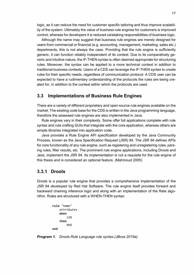
rithm. Rules are structured with a WHEN-THEN syntax:
rule "name" attributes when LHS then RHS end
Program 1. Drools Rule Language rule syntax.(JBoss 2019a)
18
The rules are saved in Drools Rule Language (DRL) files with the drl file extension. Rules
can either be generated by hand, or by utilizing a GUI built for crafting new rules. The
left-hand side (LHS) condition typically matches to a simple Java object’s attribute in the
data model of the application. An example from the Drools documentation:
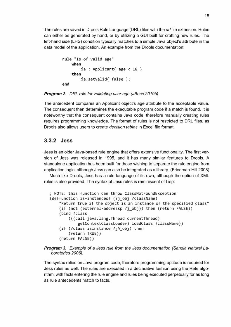
rule "Is of valid age" when $a : Applicant( age < 18 ) then $a.setValid( false ); end
Program 2. DRL rule for validating user age.(JBoss 2019b)
The antecedent compares an Applicant object’s age attribute to the acceptable value.
The consequent then determines the executable program code if a match is found. It is
noteworthy that the consequent contains Java code, therefore manually creating rules
requires programming knowledge. The format of rules is not restricted to DRL files, as
Drools also allows users to create decision tables in Excel file format.
3.3.2 Jess
Jess is an older Java-based rule engine that offers extensive functionality. The first ver-
sion of Jess was released in 1995, and it has many similar features to Drools. A
standalone application has been built for those wishing to separate the rule engine from
application logic, although Jess can also be integrated as a library. (Friedman-Hill 2008)
Much like Drools, Jess has a rule language of its own, although the option of XML
rules is also provided. The syntax of Jess rules is reminiscent of Lisp:
; NOTE: this function can throw ClassNotFoundException (deffunction is-instanceof (?j_obj ?className) "Return true if the object is an instance of the specified class" (if (not (external-addressp ?j_obj)) then (return FALSE)) (bind ?class (((call java.lang.Thread currentThread) getContextClassLoader) loadClass ?className)) (if (?class isInstance ?j§_obj) then (return TRUE)) (return FALSE))
Program 3. Example of a Jess rule from the Jess documentation (Sandia Natural La-boratories 2006).
The syntax relies on Java program code, therefore programming aptitude is required for
Jess rules as well. The rules are executed in a declarative fashion using the Rete algo-
rithm, with facts entering the rule engine and rules being executed perpetually for as long
as rule antecedents match to facts.

19
Furthermore, much like Drools, Jess is augmented with rule creation tools. A devel-
opment environment called JessDE consists of plug-ins for the Eclipse Integrated Devel-
opment Environment (IDE). (Sandia National Laboratories 2013)
3.3.3 Easy Rules
Compared to the previous two examples, Easy Rules is a relatively lightweight library
intended to be implemented into Java code. Firstly, the Easy Rules rule syntax relies on
annotations to Java code, whereby all rules are integrated into the code as Java classes.
This prevents users of the application from creating their own rules or would require a
separate user interface component for instantiating rule objects. (Hassine 2018)
Secondly, the library provides more options and control to the rule creator by offering
an expression language for rule creation. The supported expression language is the
MVFLEX Expression Language (MVEL), a language developed for embedding expres-
sions into Java code (Brock 2019). An expression language enables the rule creator to
create more complex rules, as expressions can be more dynamic than regular Java code
due to their runtime evaluation. MVEL expressions can capture variables from Java code
via annotations.
Thirdly, the library provides users of its rule engine with the ability to create rules using
YAML files. The file contains the required metadata for the rule (name, description) along
with the standard antecedents and consequents.
name: "weather rule" description: "if it rains then take an umbrella" condition: "rain == true" actions: - "System.out.println(\"It rains, take an umbrella!\");"
Program 4. Easy Rules YAML rule structure (Hassine 2018) .
Unlike the previous two rule engine examples, Easy Rules does not come with a GUI for
crafting rules, leaving the burden of rule creation to the user of the library. However, Easy
Rules does adequately provide core rule engine functionality, which could be extended
to the purposes of the user.
3.4 Evaluation of Rule Engines and Rule Syntax
Comparison of existing rule engines revealed insights into the commonalities of Java
based rule engines. In general, more mature rule engines seek to provide end-to-end
support for their use. As the purpose of a rule engine is to expose business logic to the
control of the user, the user must be able to express business logic in a manner that is
understandable and less programmatic.
Although the advanced rule engines, Drools and Jess, both had rule syntaxes that
required some degree of programming knowledge, they both attempt to circumvent this
expertise requirement by providing a GUI. In the context of this thesis, users of the rule
engine of the CDS can be expected to understand the content for which they are creating
rules (i.e. message structure of communication protocols) but are not expected to have

20
programming expertise. Due to these constraints, the rule engine will either need a sim-
ple enough rule syntax for non-technical users to be able to craft rules or provide a GUI
that will automatically create rules using correct syntax. Considering that all three rule
syntaxes evaluated above all require programming knowledge, a feasible solution would
be to create a separate rule creation GUI.
A separate rule creation GUI has other advantages. It enables a more human-reada-
ble interface for creating rules, so that the user does not need to edit a rule file in a text
editor. Furthermore, the GUI can restrict the set of available options so that it is impos-
sible or difficult for the user to create illegal rules. In addition, offering a GUI removes
restrictions on rule syntax (verbosity, human readability, etc.), as the user is not exposed
to the rule syntax during application use.
The rule syntax of the rule engines in the previous section are all built on the IF-THEN
structure. The Drools Rule Language rule syntax resembles clear English instructions,
although it embeds Java method calls. Even though Java is a verbose language, method
calls are not considered user friendly. Moreover, they require knowledge of the underly-
ing code, further reducing the level of abstraction of the rules. The Jess rule syntax is no
less user friendly in this respect, as the Lisp-like rule syntax can be difficult to read even
for technical users. The expression power of the Jess and Easy Rules’ MVEL syntax
does empower rule creators with ample tools to create dynamic and complex rules, how-
ever it does not promote a simple user experience. Although the rule engine of this thesis
can be expected to receive valid rules, the objective of the rule engine itself is to be
protocol agnostic. As such, the implementation will attempt to keep the level of abstrac-
tion of rules at a high level, so that no Java code need be embedded into the rule syntax.
The requirements set for the CDS will impose stringent security requirements on the
rule engine. Choosing to integrate a third-party rule engine into the application introduces
new potential avenues of attack for the application, leading to greater risk for the overall
system. Furthermore, the complexity of a rule engine the likes of Drools would require
significant time investment for learning facets such as configuration and operation of the
engine. As part of the Knowledge Is Everything (KIE) framework, Drools has significantly
more features that has been presented in the previous section. Many of these features
are likely to be redundant for the use case of the CDS and introduce more risk into the
system. Jess and Easy Rules both present similar challenges, although both are lighter
systems than Drools. Easy Rules, being the most lightweight of the three, would naturally
be the simplest to integrate into the CDS.
The rule engine of this CDS will be developed based on the best practices present
within other rule engines, but will not incorporate Drools, Jess nor Easy Rules into the
solution. Incorporating a third-party rule engine would mean that the core business logic
of the CDS is comprised of third-party code, which has security and risk management
implications. From a business standpoint, utilizing one of the available solutions was not
feasible. As a result, the rule engine of this thesis will be designed and implemented by
the CDS team based on the best practices of the existing rule engine implementations.
21
4. COMMUNICATION PROTOCOLS
The objective of the rule engine of this thesis is to achieve protocol agnostic functionality.
The initial protocols to be implemented are ASTERIX and HLA, as they are required
protocols for the CDS itself. A general overview of their structures is provided in order to
highlight the differences between the protocols and to demonstrate the challenges with
converting from one protocol to another. More importantly, comprehension of the simi-
larities between the two protocols is critical to designing a rule engine that can process
protocols in a generic fashion.
4.1 ASTERIX
The All-purpose Structured EUROCONTROL Surveillance Information Exchange (AS-
TERIX) is a data transfer protocol employed in both military and civilian aviation. The
purpose of the protocol is to provide a lightweight data transfer solution for sending mes-
sages by utilizing bit mappings to provide metadata on messages’ payloads. In practice,
the protocol is designed for aviation surveillance data, including radar sensor data and
aircraft flight data. The protocol’s structure is outlined in EUROCONTROL’s protocol
specification. (EUROCONTROL 2016)
In the protocol specification, the protocol’s requirements are split into three catego-
ries: mandatory, recommended and optional. As such, a minimum working implementa-
tion of the ASTERIX protocol contains implementations for all mandatory requirements,
whereas recommended and optional requirements help provide better compliance with
other ASTERIX implementations but are not compulsory. Coverage of mandatory re-
quirements is sufficient for the purposes of this thesis.
An ASTERIX message consists of a group of data blocks. Each block contains the
payload of the message, along with identifying metadata. A data block must always con-
tain its data category (CAT). The category is determined by an octet, thereby allowing
for 256 possible Data Categories. Categories are reserved so that:
Values 000-127 are intended for standard applications
Values 128-240 are for special applications
Values 241-255 are reserved for non-standard applications
All categories are intended both for civilian and military use. In addition to the data
category, the message’s metadata must also include a length indicator (LEN). It consists
of two octets that indicate the total length of the message, expressed in octets, including
the message’s metadata (CAT and LEN). A variable number of data records follows
message metadata.

22
Figure 7. Structure of a Data Block.(EUROCONTROL 2016)
All data records contain a Field Specification (FSPEC) identifying the data fields present
in the message. The FSPEC resembles a “table of contents” for the message, as it states
which data fields are present in the message. Each data field is marked as present (bit
value of one) or absent (bit value zero). The indices of FSPEC bits map to a data field
table called a User Application Profile (UAP), which elaborates on the content of the data
field by providing a label and a length in octets. Both sending and receiving ASTERIX
applications require knowledge of the UAP in order to be able to process messages.
Figure 8. Field specifications in ASTERIX messages.(EUROCONTROL 2016)
Fields specifications can be sequenced via the Field Extension Indicator (FX), the last
bit of the octet. Settings the FX bit to one signifies consecutive FSPEC octets.

23
The number of prudent FSPEC octets is determined by the UAP, as each FSPEC bit
must map to a meaningful data field in the UAP.
Table 1. The standard UAP for CAT034 messages. (EUROCONTROL 2007)
The table above denotes the standard UAP set for category 034 messages. The stand-
ard UAP requires CAT034 messages to include two FSPEC octets, even if the bits in the
latter FSPEC are all set to zero. Data fields define data items, which also are outlined in
the protocol specification. Furthermore, the specification is required to explicitly state the
optionality of data items.
The data fields themselves can be structured in several different ways, due to the
possibility of variable length data fields (see Figure 9). The simplest type of data field has
a fixed length, as represented by the single digit lengths in the table above. Alternatively,
the data field can be of a variable but explicitly declared length, which is stated in the first
octet of the data field. However, some data fields can contain chained data fields that
are linked with a FX bit, in a manner similar to FSPEC octets.
Additionally, data fields can be expressed as a repetition. In this case, the field itself
has a predetermined length that is repeated a variable number of times designated by
its Field Repetition Indicator (REP). At the binary level, the REP is represented by the
leading octet in the data field. Another variable type is the compound data field, which is
a combination of the previous field types. A compound data field consists of the primary
subfield, which can be followed by a variable set of data subfields that are of varying
length. The primary subfield is joined to the data subfields using a FX bit and data sub-
fields can be of extensible, explicit or repetitive length.

24
Figure 9. Data field structure. (EUROCONTROL 2016)
Finally, the ASTERIX protocol uses System Area Codes (SAC) and System identification
Codes (SIC) to uniquely identify actors within the network. The SAC is set by the AS-
TERIX Maintenance Group (AMG) and is tied to a certain geographical area, most often
a country. System identification codes are assigned by the nation controlling the geo-
graphic area identified by the SAC. Both SIC, and SAC are comprised of one octet each.
The SIC/SAC codes are present in messages where having a unique identifier is rele-
vant.
4.2 HLA
The Higher-Level Architecture is a communication protocol for distributed simulations
developed by the Simulations Interoperability Standards Organization (SISO). Primarily
the HLA has been developed for military simulations, although applications have recently
been developed also for civilian domains. Its purpose is to provide an interface for com-
munication of both virtual and real-world objects between multiple simulators. The HLA
is a more recent alternative to the older Distributed Interactive Simulation (DIS) protocol.
(Dahmann 1998)
Similar to ASTERIX’s concept of the field specification, the Federation Object Model,
commonly abbreviated as FOM, determines HLA message content. All participants must
adhere to the FOM’s message structure in order to be able to participate in a distributed
simulation. In the terminology of the HLA, simulators or supporting applications belong-
ing to a distributed simulation are called federates. Federates communicate using a pub-
lisher-subscriber pattern, whereby federates notify a central middleware of their interest
in any given type of object. Federates subscribe to incoming events related to objects of
interest and publish events related to objects within their own simulations. In the context
of the HLA, the middleware is called the Run-time Infrastructure (RTI) and it acts as a
message broker for the system. The combination of all participating federates, the RTI
middleware and the FOM altogether form a federation. (Strassburger 2002)
25
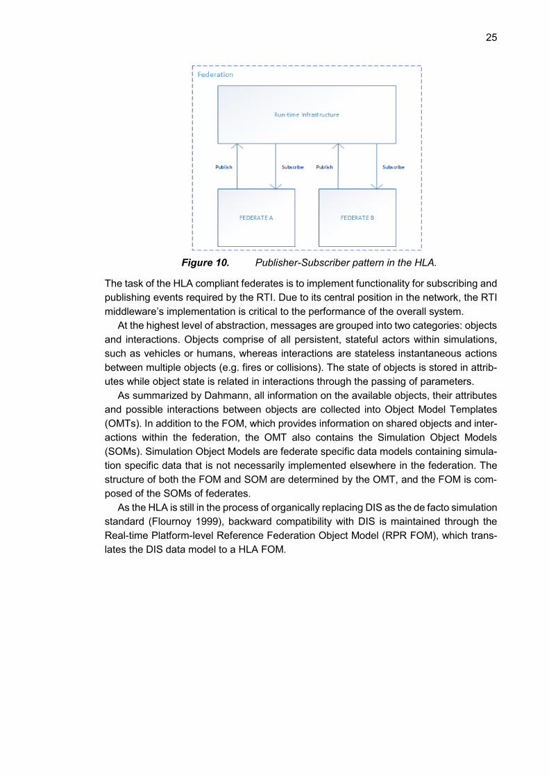
Figure 10. Publisher-Subscriber pattern in the HLA.
The task of the HLA compliant federates is to implement functionality for subscribing and
publishing events required by the RTI. Due to its central position in the network, the RTI
middleware’s implementation is critical to the performance of the overall system.
At the highest level of abstraction, messages are grouped into two categories: objects
and interactions. Objects comprise of all persistent, stateful actors within simulations,
such as vehicles or humans, whereas interactions are stateless instantaneous actions
between multiple objects (e.g. fires or collisions). The state of objects is stored in attrib-
utes while object state is related in interactions through the passing of parameters.
As summarized by Dahmann, all information on the available objects, their attributes
and possible interactions between objects are collected into Object Model Templates
(OMTs). In addition to the FOM, which provides information on shared objects and inter-
actions within the federation, the OMT also contains the Simulation Object Models
(SOMs). Simulation Object Models are federate specific data models containing simula-
tion specific data that is not necessarily implemented elsewhere in the federation. The
structure of both the FOM and SOM are determined by the OMT, and the FOM is com-
posed of the SOMs of federates.
As the HLA is still in the process of organically replacing DIS as the de facto simulation
standard (Flournoy 1999), backward compatibility with DIS is maintained through the
Real-time Platform-level Reference Federation Object Model (RPR FOM), which trans-
lates the DIS data model to a HLA FOM.

26
Figure 11. A section of the RPR FOM Object Class Hierarchy (SISO 2015).
As is common with object-oriented architectures, objects in the HLA data model are ar-
ranged into a hierarchy. Figure 11 illustrates a typical graphical representation of HLA
object hierarchy where FOM modules are presented with the same color. According to
the figure, a HLA Aircraft object inherits from Platform, which inherits from PhysicalEntity
and finally from BaseEntity. Unlike ASTERIX, the HLA does not provide any implemen-
tation specific granular requirements for the structure and transfer of HLA data. On the
contrary, the HLA leaves implementation details in the hands of the RTI implementer.
(SISO 2015)
Instead of receiving raw byte data, federates transfer data in the form of API calls to
the RTI. RTI implementations often provide APIs in more than one programming lan-
guage, the most common languages being C/C++ and Java. In spite of this, the structure
of the FOM is not tied to the RTI implementation, but rather to the HLA standard the RTI
implements. The most prevalent standards for the HLA are the IEEE 1516-2000 and HLA
1.3. (Imbrogno, Robbins et al. 2004)
4.3 Comparison of Chosen Protocols
Comparison of both ASTERIX and HLA reveal several differences and similarities.
Firstly, the manner in which messages are transferred is dissimilar. ASTERIX messages
are transferred as raw byte data that requires protocol specific parsing, whereas HLA
messages are passed as events to the RTI in a publisher-subscriber fashion.
Despite the difference in data transfer, the structure of the messages themselves is
relatively similar. Both protocols have a predetermined structure for the potential mes-
sages available (FOM and UAP) to communicating parties. Additionally, the structure of
both protocols is multilayered. HLA messages naturally have multiple layers due to their
hierarchical characteristics, whereas ASTERIX messages have an initial definition layer
in the form of the FSPEC, followed by consequent Data Fields that each contain Data
Items.

27
The hierarchical structure of the two protocols suggests that a common generic form
for cross-domain messages may be possible. In order to achieve protocol agnosticism
for the rule engine, the rule engine must be able to process both ASTERIX and HLA
messages in the same manner. Assessment of the commonalities between the two pro-
tocols suggests that both can be represented in a multilayered structure.
Figure 12. A generic message format.
At the most atomic level, both ASTERIX and HLA messages consist of key-value pairs.
Each key represents a field in the message, whereas the value contains the data payload
of the field. For ASTERIX the key would be the Data Field and the value would be its
respective Data Item. In the HLA, the name and value of a simulation object’s attribute
would constitute an instantiation of the key-value pair.
Structurally, key-value pairs are nodes or elements of the message. As both protocols
are multileveled, the natural manner to structure the nodes is in a tree data structure. In
this manner for example HLA object hierarchies can easily be arranged so that accessing
parents and children of objects becomes trivial. Similarly, chained ASTERIX messages
can be structured in multiple layers.
Based on the structure of ASTERIX and the HLA, a generic message structure is
proposed for the rule engine as illustrated in Figure 12. By restructuring messages into
the proposed format, the engine can be built to operate on nodes in a tree structure,
instead of protocol specific objects. As a result, the rule engine requires no knowledge
on the protocol it is processing.
It is however unclear whether the proposed structure generalizes to all communication
protocols. Analysis of generalization capabilities would require assessment of more pro-
tocols. For the purposes of rule engine of this thesis, and the protocols it supports, the
tree structure is deemed sufficiently generic.
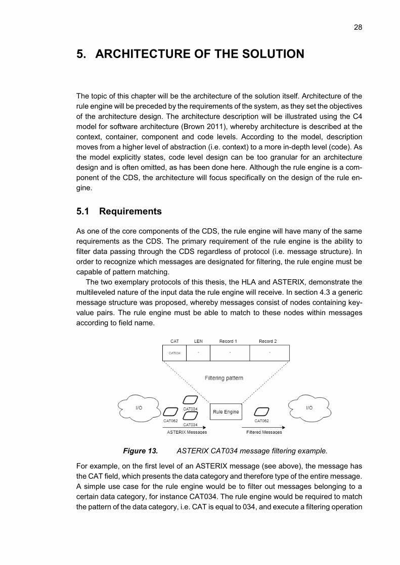
28
5. ARCHITECTURE OF THE SOLUTION
The topic of this chapter will be the architecture of the solution itself. Architecture of the
rule engine will be preceded by the requirements of the system, as they set the objectives
of the architecture design. The architecture description will be illustrated using the C4
model for software architecture (Brown 2011), whereby architecture is described at the
context, container, component and code levels. According to the model, description
moves from a higher level of abstraction (i.e. context) to a more in-depth level (code). As
the model explicitly states, code level design can be too granular for an architecture
design and is often omitted, as has been done here. Although the rule engine is a com-
ponent of the CDS, the architecture will focus specifically on the design of the rule en-
gine.
5.1 Requirements
As one of the core components of the CDS, the rule engine will have many of the same
requirements as the CDS. The primary requirement of the rule engine is the ability to
filter data passing through the CDS regardless of protocol (i.e. message structure). In
order to recognize which messages are designated for filtering, the rule engine must be
capable of pattern matching.
The two exemplary protocols of this thesis, the HLA and ASTERIX, demonstrate the
multileveled nature of the input data the rule engine will receive. In section 4.3 a generic
message structure was proposed, whereby messages consist of nodes containing key-
value pairs. The rule engine must be able to match to these nodes within messages
according to field name.
Figure 13. ASTERIX CAT034 message filtering example.
For example, on the first level of an ASTERIX message (see above), the message has
the CAT field, which presents the data category and therefore type of the entire message.
A simple use case for the rule engine would be to filter out messages belonging to a
certain data category, for instance CAT034. The rule engine would be required to match
the pattern of the data category, i.e. CAT is equal to 034, and execute a filtering operation
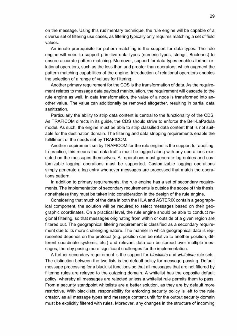
29
on the message. Using this rudimentary technique, the rule engine will be capable of a
diverse set of filtering use cases, as filtering typically only requires matching a set of field
values.
An innate prerequisite for pattern matching is the support for data types. The rule
engine will need to support primitive data types (numeric types, strings, Booleans) to
ensure accurate pattern matching. Moreover, support for data types enables further re-
lational operators, such as the less than and greater than operators, which augment the
pattern matching capabilities of the engine. Introduction of relational operators enables
the selection of a range of values for filtering.
Another primary requirement for the CDS is the transformation of data. As the require-
ment relates to message data payload manipulation, the requirement will cascade to the
rule engine as well. In data transformation, the value of a node is transformed into an-
other value. The value can additionally be removed altogether, resulting in partial data
sanitization.
Particularly the ability to strip data content is central to the functionality of the CDS.
As TRAFICOM directs in its guide, the CDS should strive to enforce the Bell-LaPadula
model. As such, the engine must be able to strip classified data content that is not suit-
able for the destination domain. The filtering and data stripping requirements enable the
fulfillment of the needs set by TRAFICOM.
Another requirement set by TRAFICOM for the rule engine is the support for auditing.
In practice, this means that data traffic must be logged along with any operations exe-
cuted on the messages themselves. All operations must generate log entries and cus-
tomizable logging operations must be supported. Customizable logging operations
simply generate a log entry whenever messages are processed that match the opera-
tions pattern.
In addition to primary requirements, the rule engine has a set of secondary require-
ments. The implementation of secondary requirements is outside the scope of this thesis,
nonetheless they must be taken into consideration in the design of the rule engine.
Considering that much of the data in both the HLA and ASTERIX contain a geograph-
ical component, the solution will be required to select messages based on their geo-
graphic coordinates. On a practical level, the rule engine should be able to conduct re-
gional filtering, so that messages originating from within or outside of a given region are
filtered out. The geographical filtering requirement is classified as a secondary require-
ment due to its more challenging nature. The manner in which geographical data is rep-
resented depends on the protocol (e.g. position can be relative to another position, dif-
ferent coordinate systems, etc.) and relevant data can be spread over multiple mes-
sages, thereby posing more significant challenges for the implementation.
A further secondary requirement is the support for blacklists and whitelists rule sets.
The distinction between the two lists is the default policy for message passing. Default
message processing for a blacklist functions so that all messages that are not filtered by
filtering rules are relayed to the outgoing domain. A whitelist has the opposite default
policy, whereby all messages are rejected unless a whitelist rule permits them to pass.
From a security standpoint whitelists are a better solution, as they are by default more
restrictive. With blacklists, responsibility for enforcing security policy is left to the rule
creator, as all message types and message content unfit for the output security domain
must be explicitly filtered with rules. Moreover, any changes in the structure of incoming

30
messages requires consequent changes in blacklist rules. Possible structural changes
include the addition of new types of messages or addition of new fields to old message
types. A blacklist has to add new rules for each change.
Implementation of primary requirements results in a blacklist solution. However, us-
age of both blacklist and whitelist rule sets concurrently is not possible in this implemen-
tation, therefore additional blacklist and whitelist rule types are necessary. Furthermore,
the addition of explicit blacklist and whitelist rule types reduces the amount of manual
work for users in rule creation, leading to improved usability of the system.
5.2 Context
The System Context diagram describes the actors that interact with the CDS software
application. As the rule engine is a central component of the CDS, the System Context
diagram is similar to the context diagram of the CDS itself.
Figure 14. System Context diagram for the Cross-Domain Solution.
The figure above illustrates the System Context of the CDS. It contains four main actors,
which are relevant to the CDS: the primary input from Actor A, primary output to Actor B,
the rule set from the user of the CDS and the auditor of the CDS. Actors A and B both
are software components, or a conglomeration of software components, attempting to
interact with one another. As they belong to disparate security domains, the CDS acts
as an interface between them. It is important to note that although the diagram above
implies unidirectionality, in practice the solution can operate bidirectionally. From a logi-
cal standpoint, the application enables bidirectionality by adding two unidirectional con-
nections in opposite directions.
The non-software actor providing input to the system is the user. The user will gener-
ate the rules which dictate the functioning principles of the engine itself. Rules determine
what data passes through the rule engine, in addition to any potential field manipulations

31
on messages. The user is presumed to be well versed in the structure of the forwarded
protocol but cannot be expected to have technical or programming expertise. As such,
the user can be characterized as a business knowledge worker (see section 3.2). More-
over, users can be expected to create rules that are validated upon creation.
The auditor is an external party, such as a system administrator, who is required to
have access to the system’s logs. Logging includes any events where the content of
messages is manipulated, errors, illegal messages in addition to normal software behav-
ior. Moreover, logging behavior can be customized further with logging rules. In addition
to auditing, logging provides the capability to retrospectively analyze operation of the
CDS. This is particularly useful in cases where the CDS might not have functioned as
expected.
The next chapter is centered on the CDS application itself and the containers within
it. Containers can be considered as logical collections of software components that can
be running even as standalone processes. In the context of this thesis, the presented
containers are separate modules or data sources that affect core application logic.
5.3 Containers
The Container diagram of the rule engine mirrors the System Context diagram of the
CDS, as the engine contains the core operating logic of the CDS. Moreover, they both
share the same number of inputs and outputs, due to the fact that the rule engine oper-
ates only on the messages themselves and does not produce side-effects.
The purpose of a container diagram is to increase the level of detail on the application
in question without going into program code or software components. It provides the
context for the core software component, i.e. the rule engine, in the CDS software pro-
gram. Furthermore, it highlights the data transfer between the containers to provide an
indication of the flow of information and additionally the manner in which the data was
transferred. (Brown 2011)
Figure 15. The Container diagram of the rule engine.
The Container diagram of the rule engine is divided into two inputs and two outputs. The
inputs consist of messages that are parsed into a generic form for the rule engine, as
32
well as the rules that make up the knowledge base of the engine. The first output is
composed of log data generated by the filtering process, whereas the second output
comprises of the messages the rule engine sends. The primary input of the system is
the parsed data received from the first protocol adapter. Although the rule engine is in-
tended to be protocol agnostic, the content of the messages must still be parsed and
collected into a comprehendible format. Considering that the content of different com-
munication protocols varies greatly, the only feasible manner to process their message
data is to build adapters capable of parsing the protocol. A strength of the system is that
the core functionality of the component can remain agnostic to the protocol, so long as
the parsed data is in a suitable format. Support for further protocols can be extended
with the addition of more adapters.
The protocol adapters are responsible for compliance with several of the constraints
set by TRAFICOM. The constraints set by the communication agency are centered on
maintaining a robust system that ensures fault tolerance and message protocol compli-
ance for the CDS application (see section 2.3.2). Moreover, any input into the system
presents potential avenues of attack for malicious users, therefore the adapter must be
capable of processing intentionally incorrect data, in addition to otherwise faulty or mal-
formed data. Implementation of the constraints set by TRAFICOM provides protection
against common attacks, such as the denial of service (DoS) attack.
Although the detailed functionality of the adapters is outside the scope of this thesis,
it is important to understand their responsibilities relative to the rule engine, in addition
to their output format. The role of the adapters is critical in achieving protocol agnostic
functionality for the rule engine.
A core task of the protocol adapters is the ability to verify compliance with the chosen
communication protocol. Compliance checks include the verification of message length
for all fields of the message. For example, ASTERIX explicitly determines the length of
all data items in octets, therefore the adapter must have the User Application Profile for
all supported message categories. Additionally, protocol compliance requires that mes-
sage structure is valid. Received messages must have all the fields required by the mes-
sage type for any given protocol. In the HLA, message structure is determined by the
FOM, which delineates the possible fields and their respective data types of each sup-
ported object (i.e. message). Moreover, the FOM dictates which fields are mandatory
and which are optional. At the protocol level, the ASTERIX UAP fulfills similar tasks to
the HLA FOM, whereas for individual messages the FSPEC signifies the presence and
absence of data fields in a message.
In addition to the demands set by TRAFICOM, the adapter fulfills several of the pre-
processing requirements of the rule engine. As the rule engine must comprehend data
types of values, the protocol adapter is charged with converting byte data into the primi-
tive types supported by the rule engine. Moreover, the adapter transforms the message
data into a generic form so that the rules created for the engine do not need to be tied to
a communication protocol.
The chosen generic message structure is predicated on the hypothesis that the mes-
sage structure of arbitrary communication protocols can generally be reorganized into a
multilayered format. The hypothesis is based on the two example communication proto-
cols of this thesis, ASTERIX and the HLA. Protocol adapters restructure messages into
33
the form illustrated in Figure 12 for the rule engine to process. Message fields are deter-
mined by the protocol’s specification, as are the data types of values.
Considering that the most atomic component of the message is a key-value pair, the
natural data structure for this type of representation is the hash map. However, a single-
leveled hash map does not reflect the treelike structure of the messages, therefore ad-
ditional layers are added to the message by nesting hash maps. Each hash map repre-
sents one layer of the message and iteration between levels happens through succes-
sive hash function calls. For example, in Figure 12 manipulation of Value G would require
hashing Field A and consequently hashing Field G.
Messages have the capacity for a more complex structure than previously described.
Besides the primitive data types and nested maps, the value of a key-value pair can also
contain a list of values, which can theoretically contain further nested data structures.
While lists can be considered relatively uncommon, they are required for protocols such
as the HLA. For example, HLA object attributes can be placed within a list for certain
classes. Nevertheless, for the purposes of this thesis lists will be expected to contain
content of primitive type, and therefore ignore any nested content within lists.
The usage of nested maps is also beneficial for performance reasons. Hash function
calls are performed at constant time (Cormen et al. 2009), ergo accessing message el-
ements also occurs at constant time. Message nodes within a single message are ac-
cessed multiple times when passing through the rule engine, therefore efficiency in node
access time complexity is critical to the performance of the system.
The messages enter the rule engine in generic form, but no operations are executed
on the messages without the second input to the system: the rules. The rules are brought
to the system in serialized form via the file system. As displayed in the System Context
diagram, the user creates the rules, which are transferred to the application in serialized
form. Much like the other input of the system, i.e. the protocol adapter, the rules must
also be validated before reading. Validation occurs in a similar manner to the messages;
the serialized rules must comply with valid rule syntax and semantics. In practice, a com-
mon implementation of this is validation against a schema. The schema ensures valid
structure, in addition to data type and content length restrictions.
All events that occur within the rule engine generate log entries that are passed to a
logger. Log entries are given different log levels in order to facilitate quicker log analysis
and error diagnosis. Regular unfiltered data traffic is logged at the INFO level, the firing
of rules is logged at WARN level and any exceptions or errors are logged at the ERROR
level. The logged data can then be routed to a destination of the user’s choosing.
Finally, the output of the second adapter passes the filtered data outside of the CDS.
The adapter receives messages that have been passed through the rule engine. The
engine is capable of transforming messages into a significantly altered form, as each
message field can be replaced with a new value. Details of available message manipu-
lations are outlined in the next section. Received messages at the output adapter can
therefore be vastly different compared to the input messages at the first adapter. The
role of the adapter is the direct reverse of the first adapter; to convert the messages from
generic form back to byte data for data transfer.
Similar to the first adapter, the second adapter has the same responsibilities when it
comes to validating protocol compliance. Due to the generic nature of the rules, the user
could theoretically create rules that transform messages into a non-compliant form. This

34
is a known trade-off for implementing protocol-agnostic functionality for the rule engine
therefore it is the responsibility of the rule creator to prepare correct rules that do not
perform illegal transformations.
The Container diagram displays the implementations of several of the security princi-
ples mentioned in section 2.2. The transformation of data from byte data to generic for-
mat and back to byte data is an implementation of the defense-in-depth model, due to
the multiple layers of controls a message undergoes. In addition to the two adapters
each adding a layer of security, the rule engine itself naturally has the potential to perform
stringent security checks on messages and can therefore be considered another security
layer. Multiple layers of message scrutiny increase the likelihood of preventing unauthor-
ized messages from reaching the output security domain.
Moreover, the rule engine enables the partial enforcement of the Bell-LaPadula model
via confidentiality enforcement. Sanitizing (i.e. removing) sensitive fields or altogether
filtering sensitive messages reduces the potential for data leakage. Message content
manipulation enables the censorship of message content so that its classification level
is reduced to the level of the output domain, thereby ensuring that actors in the domain
are not able to read data from a higher security classification (i.e. “no read up”). However,
the model states that “writing down” is not permitted, which does not occur in this case.
As the rule engine is the focus of this thesis, the next section focuses more on the
engine’s structure at the component level. The displayed components highlight the gen-
eral functionality of the engine, in addition to providing insight on the rules themselves.

35
5.4 Components
The Component diagram delves deeper into the structure of the rule engine at a software
component level. In terms of content, the diagram displays the central components in
addition to the interfaces between them. Interfaces are annotated with the data being
passed between the interface and its caller.
Figure 16. Component diagram of the rule engine.
At the core of the rule engine is the filter engine. It acts as the central business logic
controller for the rule engine, therefore its primary role is to direct data flow in the correct
direction. It receives messages in their generic form from the protocol adapter and
passes them to the Condition Matcher component for message processing.
Before message processing, the Rule Parser parses the rules and passes them to
the Filter Engine. The parsing process begins with the serialized rules, along with the
schema, being read from the file system. The parser reads the serialized rule set, which
contains all the rules for the rule engine. Each rule set is tied to a single connection;
therefore, all rules are logically unidirectional. Rules are validated so that they conform
to the following structure:

36
Figure 17. Representation of rule structure.
The chosen structure for the rules is a variation of the idiomatic IF-THEN syntax. As
detailed in the previous section, the technique for achieving protocol agnosticism relies
on the generic messages structure. Similarly, the rule schema is predicated on mes-
sages being arranged in a tree structure. According to the schema, a rule contains at
least one condition and at least one operation. Conditions select messages that trigger
the rule, whereas the operation determines the nature of the field transformations on the
selected messages. The components of the rule will be referred to as elements in order
to distinguish them from their counterparts in messages.
The condition element of the rule (i.e. the antecedent) attempts to select a single node
from the generic message. Message fields are selected with a series of keys given in the
field element of the condition. As the sequence of keys depends on the protocol, the list
of keys is a variable set of arguments. The number of keys signifies the level or layer of
the entry being selected. Followed by the field is the operator that is used for comparing
the value. Rules support the typical relational operators:
Equals
Not equals
Greater than
Less than
Greater than inclusive
Less than inclusive
The operator compares the value of the given field in a message to the value element
of the condition. Although the conditions have a relatively simple structure, they enable
a diverse set of selection capabilities for messages. Even though a variable argument
list of keys requires the rule creator to know the full structure of the message, it also
guards against making incorrect selections in cases where field names are not neces-
sarily unique within a message. For example, a field named type, or a derivative name,
could be present in multiple layers or sections of a message, therefore presenting the
full set of keys to the desired field prevents selecting all type fields.
Relational operators on the other hand enable the selection of a range of values. By
providing two conditions with an upper and lower limit for numerical values, the rule se-
lects all values in between. However, this requires that the data type of the value is ad-
equate for the relational operator, as data types such as strings are not compatible with

37
all operators (e.g. the greater than operator). Moreover, the data type of the value ele-
ment must match that of the message’s corresponding value.
The condition is followed by the consequent, i.e. the operation. An operation is anno-
tated with the type, field, old value and new value elements. The type signifies the type
of operation, as although the engine initially only supports both field replacement and
message filtering operations, the intention is to enable support for more types in the
future. Following the type element are the field and its variable list of keys, exactly like in
the condition. The field selects the message node whose value is operated on. Unlike
the condition element however, the operation does not provide the opportunity to select
ranges of values for operations, as a single operation only transforms one field at a time.
The old value is another condition for the operation, as the value in the message must
match the old value element for the operation to be executed. If the value in the message
matches the old value element, the message value is replaced with the new value in the
message. The purpose of the old value element is to enable replacement operations in
key-value pairs where the value contains a list instead of a single element. Elements in
the list are selected for replacement based on the old value element and all matching
values are replaced with the new value.
The schema provided to the Rule Parser details the layout of rules in addition to re-
strictions on supported data types, along with any content restrictions (e.g. maximum
length of strings, permitted value ranges, etc.). Besides ensuring that the rules are valid,
the schema further prevents the rule engine from reading malicious content, thereby act-
ing as a security layer for the CDS. Moreover, the schema is not only used for validation
but also for the generation of rule objects whose instantiations the rule engine uses in its
operation. Upon reading and validating the serialized rules from the file system, the Rule
Parser instantiates rule objects and passes them to the Filter Engine.
The Condition Matcher is responsible for matching the antecedents of the rules to the
fields in the generic message. As the structure of the rules indicate, conditions are
matched with successive hash function calls on the nested maps. Each rule has its own
set of conditions that are tried for each message. All conditions within a single rule are
evaluated with the AND logical operator, whereas rules are evaluated implicitly with the
OR operator.
The figure below demonstrates the condition matching process for a generic mes-
sage. The example message has three distinct subfields entitled Field A, Field B and
Field C. Each field has a distinct string value. The three field-value pairs represent
branches within the message tree. The tree structure of the example message has been
condensed in the figure for illustrative purposes.
The Condition Matcher evaluates the rule with these three example conditions against
the generic message. The procedure for condition matching begins with set of keys for
finding the field of interest within the message. The first key, Message A, is the root node
of the tree. Subsequent keys are fields in the second tier of the message. As the Condi-
tion Matcher finds the target field, it compares its value against the value in the condition
(in this case “X”, “Y” or “Z”) with the given operator (equals). All the conditions of this
example match to each of the fields and values present within the message, therefore
the message triggers the rule. Upon triggering the rule, the message is passed from the
Condition Matcher to the Operation Executor.
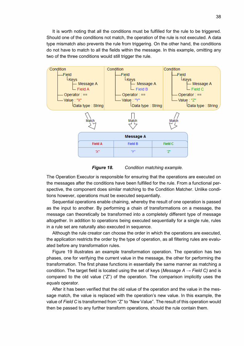
38
It is worth noting that all the conditions must be fulfilled for the rule to be triggered.
Should one of the conditions not match, the operation of the rule is not executed. A data
type mismatch also prevents the rule from triggering. On the other hand, the conditions
do not have to match to all the fields within the message. In this example, omitting any
two of the three conditions would still trigger the rule.
Figure 18. Condition matching example.
The Operation Executor is responsible for ensuring that the operations are executed on
the messages after the conditions have been fulfilled for the rule. From a functional per-
spective, the component does similar matching to the Condition Matcher. Unlike condi-
tions however, operations must be executed sequentially.
Sequential operations enable chaining, whereby the result of one operation is passed
as the input to another. By performing a chain of transformations on a message, the
message can theoretically be transformed into a completely different type of message
altogether. In addition to operations being executed sequentially for a single rule, rules
in a rule set are naturally also executed in sequence.
Although the rule creator can choose the order in which the operations are executed,
the application restricts the order by the type of operation, as all filtering rules are evalu-
ated before any transformation rules.
Figure 19 illustrates an example transformation operation. The operation has two
phases, one for verifying the current value in the message, the other for performing the
transformation. The first phase functions in essentially the same manner as matching a
condition. The target field is located using the set of keys (Message A → Field C) and is
compared to the old value (“Z”) of the operation. The comparison implicitly uses the
equals operator.
After it has been verified that the old value of the operation and the value in the mes-
sage match, the value is replaced with the operation’s new value. In this example, the
value of Field C is transformed from “Z” to “New Value”. The result of this operation would
then be passed to any further transform operations, should the rule contain them.

39
Additionally, all rules with filtering operations would already have been evaluated be-
fore evaluation of this example transformation rule.
Figure 19. Operation execution example.
Due to the protocol-agnostic nature of the rule engine, the engine is capable of morphing
messages into a completely different format compared to the original form. The engine
is not capable of recognizing protocol compliance, therefore illegal messages are re-
jected only after having left the rule engine and being passed to the outgoing protocol
adapter. This has implications for logging practices.
The logging practices applied within the rule engine are centered on providing ac-
countability of the system. All components within the engine are connected to the filter
engine and therefore pass their logs through the filter engine to the logger. Normal op-
erations, such as incoming and outgoing messages, are logged. Particularly extraordi-
nary events, e.g. messages matched by the Condition Matcher and executed operations,
are logged at a greater log level. Log level signifies the severity of the log event, with
more severe events receiving higher log levels.
The filtering functionality described above is simple to apply in practice for a protocol.
The figure below demonstrates a rudimentary filtering operation for HLA lifeforms based
on the object structure presented in Figure 11. Note that only the fields of interest for
PhsyicalEntity are displayed, all other fields have been omitted for presentation pur-
poses.
Figure 20. HLA filter rule example.

40
The rule has a condition that evaluates the value of the Lifeform node in the HLA mes-
sage. Upon condition matching the rule is triggered by the HLA message, as the value
of the Lifeform node is “NonHuman”. This leads to the operation being executed, which
in this case is a filtering operation. Notice that filtering operations do not require all the
elements required by transformation operations. As a result of filter operation, the mes-
sage is rejected and not passed to the output domain.
Considering that the CDS is a security intensive solution, the components of the rule
engine are required to be tested thoroughly. Particularly the Rule Parser, Condition
Matcher and Operation Executor require comprehensive unit testing to ensure their cor-
rect operation.
Rule Parser tests must ensure that the parser creates valid rules that conform to the
given schema. Unit tests attempt to simulate different combinations of rule sets. Rule
sets can have a plethora of combinations, as a single rule can include multiple conditions
and operations, where order is also significant. As is the case in all unit testing, the most
important test cases to consider are the limit or edge cases. Especially illegal values
(e.g. rules with too many conditions or operations, values with wrong data types) must
be rejected by the parser.
Considering that the input of the rule engine can be any nested map, it can be unit
tested with arbitrary data. Nested maps can be generated with any arbitrary fields and
values that do not have to conform to any communication protocol, such as in the exam-
ples provided in this section. This is remarkably useful for testing the Condition Matcher
and Operation Executor, as both can be tested with unorthodox message structures. The
arbitrary data can then be paired with a rule set that attempts to match to the data. In the
case of conditions, features such as range selections are subject to examination, as well
as cases where the set of keys is not found in the message. Both conditions and opera-
tions must conform to the available data types and be able to handle errors or fail grace-
fully should data types be incompatible.
Operations must be tested with assorted combinations of sequences. Sequences can
be varied both in their types (filter and transformation operations) as well as the content
of the transformations.

41
6. RESULTS AND CONSTRAINTS
This section analyzes the implementation of the rule engine. Firstly, the results of the
solution are outlined. The resulting rule engine is evaluated by reflecting on how well the
business and regulatory requirements of the solution were met. Moreover, the section
contains analysis on the degree of protocol agnosticism the result achieved and evalu-
ates the users’ ability to operate the engine.
6.1 Evaluation of Rule Engine Implementation
The rule engine has been implemented according to the architecture design detailed in
the previous chapter. The engine is capable of doing simple pattern matching with its
conditions and performing two types of operations on messages: filtering and transform-
ing.
6.1.1 Meeting Business Requirements
In terms of meeting the requirements, the solution fulfills its core responsibilities. Firstly,
the solution is capable of filtering out messages with simple key-value pattern matching
in a protocol-agnostic manner. A user can provide rules for matching to e.g. ASTERIX
CAT or SIC/SAC values or HLA BaseEntity attributes. Matched messages are then dis-
carded or transformed depending on the operations within the rules. Events of interest
are passed to the logger, which relays them forward to an auditor. All the primary re-
quirements of the rule engine were met.
The secondary requirements were not fulfilled for this iteration of the rule engine, and
their implementation demands several changes. Although blacklist rules are technically
implicitly already supported, the addition of whitelist rules requires the addition of a new
type of operation. This would introduce functional changes to the execution order of op-
erations so that both blacklist and whitelist operations can be included in a rule set. While
the addition of whitelist operations is trivial, the operation implementation requires effort.
The more challenging secondary requirement is the support for geographical filtering.
The fundamental challenge related to geographical filtering is that geographical data is
often split across multiple messages. For example, in the case of ASTERIX monoradar
data, the location of targets spotted by the radar (known as plots) are given as a refer-
ence to the position of the reporting radar. The plot reference location data is sent via
CAT048 messages, whereas radar data is sent via CAT034 messages, therefore
knowledge of the absolute location of plots requires both messages. On a practical level,
this requires a stateful implementation, whereby message values are saved in cache
memory until their complementary messages have arrived. Similarly, the HLA contains
an object hierarchy which requires a stateful CDS.
42
6.1.2 Application of Security Models
TRAFICOM sets several security principles as prerequisites for compliance to its guide,
particularly relating to data integrity and confidentiality. The main task of the protocol
adapters is essentially ensuring that data integrity remains uncompromised. Regarding
the data integrity of the rule engine, message manipulations are primarily the responsi-
bility of the rule creator. Any field transformations effectively constitute a breach of data
integrity, as manipulated data is no longer in its original intended form. As a result, the
rule engine does not inherently enforce data integrity by default.
The ability of subjects to read objects of lower or higher classification level depends
on how the data entering the engine was filtered to the outgoing domain. Crucially how-
ever, the rule engine does provide the user of the CDS with the capability to enforce
confidentiality principles.
A common technique for enforcing data confidentiality is setting a separate security
level for each field in a message. For example, the type field of a message may be given
Unclassified security level, but the author field may be classified as Secret. In this exam-
ple, the author field would need to be omitted so that the message could be sent to an
Unclassified domain. The CDS is capable of filtering out the content of unauthorized
fields according to the security level of the destination domain. Similarly, data integrity
can intentionally be compromised by slightly altering content, so that the recipient does
not receive accurate data. While these techniques compromise data integrity, they pre-
serve data confidentiality.
Although confidentiality can be enforced, the solution does not purely implement the
Bell-LaPadula model. This is due to the fact that the solution permits “write down” oper-
ations, which are not permitted according the model. From a practical standpoint, rigidly
enforcing the Bell-LaPadula model requires complex unidirectional CDS configurations,
which reduce flexibility and scalability of the application. Consequently, the solution does
not implement the Biba model either, as doing so would require the capability to “read
up”. Reading up could result in undesired data leakage and therefore compromising data
confidentiality.
The security contingencies of the solution are reinforced from a structural perspective
in the form of defense-in-depth. Multiple components within the rule engine act as a layer
of security where checks are performed on data entering the system, as has been de-
tailed in earlier sections.
6.1.3 Fulfilling TRAFICOM guidelines
In addition to the business requirements, the rule engine must also comply with the
guidelines set by TRAFICOM. The guidelines are primarily intended for a cross-domain
solution, along with any of its supporting hardware and software. Although the guidelines
are intended for the CDS as a whole, they can be evaluated from the perspective of the
rule engine, as the engine fulfills several of the core responsibilities of the CDS. The
guidelines that apply to the CDS are detailed in section 2.3.2. Most of the demands set
by TRAFICOM are enforced by the protocol adapters before messages are passed to
the rule engine.

43
Firstly, application level message structure is defined within the protocol adapters
from where the rule engine receives its input. All protocol adapters specifically detail
which protocols (or their subsections) they support. Validation ensures that only sup-
ported messages are passed to the engine. A protocol adapter rejects all messages not
conforming to its specified structure by default, therefore any erroneous messages do
not affect the performance of the CDS. As the rule engine is protocol agnostic, it cannot
ensure a specific message structure and therefore cannot perform validation nor reject
invalid messages. Requirements related to data content verification and validation are
deemed to be the responsibility of the protocol adapters.
The rule engine does however fulfill the filtering requirements set by TRAFICOM. It is
separate from other application functionality, as the engine performs only the dedicated
task of filtering. However, it does not independently comply with the requirement that
filtering must be implemented on multiple layers. Multiple layers of filtering is fulfilled by
complementing the CDS with firewalls, as was illustrated in Figure 5.
The rule engine is capable of fulfilling the tasks set for a content filtering solution.
Higher-to-lower and lower-to-higher data transfer between security domains is possible
with a correct set of filtering rules. In the higher-to-lower scenario, the responsibility of
filtering rules is to sanitize the transferred data so that its security level is reduced to the
same level as the lower security domain. After the data has been sanitized, it is fit for
transfer to the lower domain. Ergo, given a correct set of filtering rules, the rule engine
is fully capable of higher-to-lower data transfer. Lower-to-higher transfer on the other
hand does not require any filtering.
6.1.4 Protocol Agnosticism
A central objective of the solution was to create a rule engine that functions correctly,
independent of input and output protocol. The technique utilized in the rule engine of this
thesis is predicated on the structure of communication protocols being representable in
a tree structure. The rule engine is capable of processing messages so long as it is
feasible to convert them into the treelike structure detailed in section 4.3.
Both example protocols of this thesis, while serving different purposes, are simple to
translate into the previously mentioned generic structure. From the perspective of the
rule engine, it does not need to know whether the input is ASTERIX or HLA, it is fully
capable of matching conditions and executing operations on input messages. As a result,
the solution relies largely on the correct functionality of the protocol adapters, as well as
the logical validity of the input rules to achieve protocol agnosticism.
6.1.5 The Rule Engine in Practice
The CDS functions as a standalone application. It has been tested with the two example
protocols of this thesis and is fully capable of performing filtering tasks on either protocol.
Once the connection settings of the CDS have been configured, the rule engine can
import rules from the file system. New rules can be imported at runtime.
Rule creation for the engine relies on the user to be knowledgeable on the protocol
structure. Users of the implemented CDS are able to independently create rules after

44
being introduced to their structure. Rule creation is, however, significantly expediated if
the user has access to rule templates for different filtering scenarios. With a template the
user learns the correct structure for rules at a faster rate than without it. The greatest
challenge with the chosen rule structure from a usability perspective is the need for tar-
geting specific fields within messages. While knowledge of protocol structure is a pre-
requisite for users, the set of keys leading to a field is not always obvious, even to an
informed user. Outside of assembling the set of keys for a field, users find the creation
of conditions and operations intuitive. Provided that the user has received sufficient in-
formation on the structure and functionality of rules, they are fully capable of creating
them on their own.
In order to simplify the process of rule creation, the introduction of a rule creation GUI
may be prudent. Should the user be provided with a simpler interface for generating
importable rules, usability would be greatly increased. However, a GUI remains outside
the scope of this thesis.
6.2 Constraints of the Rule Engine
Although the rule engine is capable of a variety of pattern matching use cases, it does
have restrictions. The method for matching to leaf nodes requires the full set of fields
from the root node to the leaf node. Requiring the full set of fields removes the dynamism
of pattern matching, as conditions cannot be set to match for a single key-value pair
using a single target field.
Due to this reason, rules are tightly coupled with protocol message structure. The user
must know the set of fields leading to a leaf node of the message, as opposed to provid-
ing only the field whose value is compared. From a usability perspective, this is a con-
straint. However, from a security standpoint providing a set of fields reduces the proba-
bility of unintended matches, as there is no guarantee that field names are unique. Sub-
sections of messages can be regarded as a type of namespace, where each field is
unique within its namespace, but not necessarily within the entire message.
A further constraint is related to transformation rules. The operating logic for triggering
and executing transformation rules has performance implications, as it entails two pat-
tern matching operations on the message being processed; one in the condition, the
other in the operation. From a performance standpoint, it would be more efficient if the
field that was matched in the condition were also the field for operation executions. This
solution would tightly couple conditions and operations together and would remove the
possibility of having multiple conditions within one rule.
Furthermore, the sequential execution order for transformation rules imposes re-
strictions on the logical operation of the system. Considering that blocking rules are ex-
ecuted before transformation rules, the user has the ability to transform messages so
that they fulfill the conditions of one or more filtering rules, even though the message has
not been filtered by that stage. The engine does not trigger any filtering rules thereafter,
because all rules are triggered sequentially, and results of rule execution are not fed
back to the engine. In this respect, the engine does not behave as the user might expect.
Implementation of forward chaining would remedy this dilemma, as altered messages
would always be passed through the set of rules and conditions before being sent for-
ward to the output adapter.

45
Figure 21. Sequential rule triggering (left) versus forward chaining (right).
The implementation of a forward chaining inference engine may have performance im-
plications. Given that the CDS acts as an intermediary device between two domains,
which can exchange variable amounts of data between them, it is expected to bear sig-
nificant data load. A forwards chaining inference engine might pass messages through
multiple iterations of the rule set, thereby causing additional overhead that is entirely
determined by the active rule set. Additionally, forward chaining requires the creation of
a mechanism for detecting infinite loops.
Omitting forward chaining introduces a design trade-off, whereby the usability of the
system is sacrificed for performance. However, the performance of the system remains
unknown at this stage, as performance tests have yet to be implemented. The potential
implementation of forward chaining is therefore not ruled out pending the results of future
performance tests.

46
7. CONCLUSIONS
The central goal of this thesis was designing the core component of the CDS, the rule
engine, to function in a protocol agnostic manner. The solution was given a set of busi-
ness requirements along with an obligation to follow regulatory guidelines. Adhering to
TRAFICOM guidelines introduced several security requirements, as the guidelines man-
date the enforcement of defense-in-depth as well as the Bell-LaPadula models.
Context on the topic was provided with two exemplary protocols: ASTERIX and the
HLA. Both protocols differ in terms of their content but coincide in their structure. By
comparing and contrasting these structures, the common treelike nature of the commu-
nication protocols becomes apparent.
The similarity of the two protocols is that although each message has distinct content
in terms of its fields, values and data types, all of its elements can be reorganized into a
generic tree form. The hypothesis of the solution is that this generic structure generalizes
to other communication protocols as well; therefore, the rule engine can support each
protocol whose messages can be transformed into the generic tree form. Protocol ag-
nosticism of the rule engine is predicated on the aforementioned hypothesis.
An input protocol adapter restructures messages the CDS receives from byte data
into the generic tree structure. Additionally, adapters are responsible for all the validation
tasks of the CDS that ensure the messages are compliant with the given protocol. The
correct and reliable functionality of the CDS relies on the protocol adapters, as they are
central in enabling the protocol agnostic functionality of the core component, the rule
engine.
The rule engine operates on generic messages compiled by a protocol adapter. Its
operating logic is determined by the rule set it receives in serialized form. Rules deter-
mine how message nodes are matched and what operations are performed on them. As
message nodes consist of key-value pairs, rules perform pattern matching on element
keys and operations on their respective values. Relying on the premise that received
messages are always organized in tree form, the rule engine does not require knowledge
of protocol structure. The rule engine merely operates on key-value nodes within the tree
structure based on the given rule set.
In conclusion, the rule engine of this thesis is sufficiently protocol agnostic. As the rule
engine operates on generic messages based on the rule set, the responsibility of enforc-
ing protocol compliance, data confidentiality and data integrity lies with the rule creator.
While the rule engine empowers the user with the capability to prevent data leakages, it
does not do so without the correct rule set.
In addition to achieving protocol agnosticism, the rule engine fulfilled its proprietary
requirements and is mostly compliant with TRAFICOM guidelines. On the other hand,
accomplishment of secondary requirements demands additional effort. The architecture
design permits the addition of further rule types and additional protocol adapters. Other
prospective future development features include support for forward chaining for the rule
engine and an implementation for more loosely coupled pattern matching.

47
REFERENCES
BIBA, K.J., 1977. Integrity considerations for secure computer systems. MITRE CORP BEDFORD MA. Available from: https://apps.dtic.mil/docs/citations/ADA039324.
BISHOP, M., 2003. Computer security: art and science. Addison-Wesley Professional.
BRISCOE, N., 2000. Understanding the OSI 7-Layer Model. July, Available from: https://www.os3.nl/_media/2014-2015/info/5_osi_model.pdf.
Britannica Academic., 2019. Modus ponens and modus tollens. Available from: https://academic-eb-com.libproxy.tut.fi/levels/collegiate/article/modus-ponens-and-mo-dus-tollens/53169.
BROCK, M., 2019. MVEL Documentation. Available from: http://mvel.document-node.com/.
BROWN, S., 2011. The C4 Architecture Model. Available from: https://c4model.com/.
CHISHOLM, M., 2004. How to Build a Business Rules Engine. 1st ed.Morgan Kauf-mann ISBN 1558609180.
CORMEN, T.H., LEISERSON, C.E., RIVEST, R.L. and STEIN, C., 2009. Introduction to algorithms. MIT press.
DAHMANN, J.S., 1998. High Level Architecture for Simulation. July, Available from: https://ieeexplore.ieee.org/abstract/document/694563.
ESTES, A.C., 2011. Biba Integrity Model. In: Encyclopedia of Cryptography and Secu-ritySpringer, Boston, MA.
EUROCONTROL., 2016. EUROCONTROL Specification for Surveillance Data Ex-change - Part 1 . October 24, Available from: https://www.eurocontrol.int/sites/default/files/content/doc-uments/nm/asterix/Part%201%20-%20EUROCONTROL%20Specification%20AS-TERIX%20%28SPEC-149%29%20Ed%202.4.pdf.
EUROCONTROL., 2007. EUROCONTROL Standard Document for Surveillance Data Exchange Part 2b - Transmission of Monoradar Service Messages. May, Available from: https://www.eurocontrol.int/sites/default/files/content/documents/nm/asterix/ar-chives/asterix-cat034-monoradar-service-messages-next-version-of-cat-002part-2b-v1.26-112000.pdf.
FEINSTEIN, J.L., 1989. Introduction to Expert Systems. Journal of Policy Analysis and Management, vol. 8, no. 2, pp. 182-187. Available from: http://www.jstor.org.lib-proxy.tuni.fi/stable/3323375 JSTOR. ISSN 0276-8739,15206688.
FICORA., 2016. Ohje yhdyskäytäväratkaisujen suunnitteluperiaatteista ja ratkaisumal-leista
48
. June 6, Available from: https://legacy.viestintavirasto.fi/attachments/Yhdyskaytavarat-kaisuohje.pdf.
FLOURNOY, D., 1999. The HLA Mandate for DoD Simulations:Considerations for the C2 Community. May, Available from: https://www.mitre.org/publications/technical-pa-pers/the-hla-mandate-for-dod-simulations-considerations-for-the-c2-community.
FRIEDMAN-HILL, E.J., 2008. Jess Language Basics. Nov 5, Available from: https://www.jessrules.com/jess/docs/71/basics.html.
HASSINE, M.B., 2018. Easy Rules Documentation. Jan 18, Available from: https://li-braries.io/github/j-easy/easy-rules.
JACKSON, P., 1990. Introduction to expert systems. 2., repr. ed. Wokingham: Addison-Wesley ISBN 9780201175783.
JBoss., 2019a. Chapter 5. The Rule Language. Available from: https://docs.jboss.org/drools/release/5.2.0.Final/drools-expert-docs/html/ch05.html#d0e2785.
JBoss., 2019b. Community Documentation. Available from: https://docs.jboss.org/drools/release/6.3.0.CR2/drools-docs/html/ch06.html.
KUIPERS, D. and FABRO, M., 2006. Control of Systems Cyber Security: Defense in Depth Strategies. , May.
MAHMOUD, Q.H., 2005. Getting Started With the Java Rule Engine API (JSR 94): To-ward Rule-Based Applications. July 26, Available from: https://www.oracle.com/tech-network/articles/java/javarule-139829.html.
R. Lippmann, K. Ingols, C. Scott, K. Piwowarski, K. Kratkiewicz, M. Artz and R. Cun-ningham. Validating and Restoring Defense in Depth Using Attack GraphsAnonymous MILCOM 2006 - 2006 IEEE Military Communications conference, 2006.
SANDHU, R.S. On Five Definitions of Data Integrity.Anonymous DBSec, 1993.
SANDHU, R.S., 1994. Relational Database Access Controls. Available from: https://pdfs.semanticscholar.org/9d15/57c3028fc9fa3299e2bf9f118913df846399.pdf.
Sandia National Laboratories., 2013. The JessDE Developer's Environment. Nov 25, Available from: https://www.jessrules.com/jess/docs/70/eclipse.html.
Sandia Natural Laboratories., 2006. Jess Wiki: Syntax Tips. Aug 10, Available from: https://www.jessrules.com/jesswiki/view?SyntaxTips.
SISO., 2015. SISO-STD-001-2015. August 10, Available from: https://www.sisostds.org/DesktopModules/Bring2mind/DMX/API/Entries/Down-load?Command=Core_Download&EntryId=30822&PortalId=0&TabId=105.
SMITH, S.D., 2015. Shedding Light on Cross Domain Solutions. SANS Institute, No-vember 6,.

49
TAYLOR, L. and SHEPHERD, M., 2007. Chapter 7 - Determining the Certification Level. L. TAYLOR and M. SHEPHERD eds., Burlington: Syngress Available from: http://www.sciencedirect.com.libproxy.tuni.fi/science/arti-cle/pii/B9781597491167500123 ISBN 9781-597491167. DOI //doi-org.lib-proxy.tuni.fi/10.1016/B978-159749116-7/50012-3 ".
USNRC., 2018. Defense in Depth. July 6, Available from: https://www.nrc.gov/reading-
rm/basic-ref/glossary/defense-in-depth.html.