designing a static dial plan - ki agh · designing a static dial plan version history this...
TRANSCRIPT

1dp3_isd
Designing a Static Dial Plan
Version History
This solutions document describes how to design and implement static H.323 dial plans and how toconfigure and manage static H.323 dial plans on gateway and gatekeeper platforms for large Voice overIP (VoIP) networks.
This document includes the following sections:
• Introduction, page 1
• Design Methodology for Large-Scale Dial Plans, page 5
• H.323 Network Components in Large-Scale Dial Plans, page 26
• Use of Translation Rules, Technology Prefixes, and Dial Peer Failover Example, page 34
• Implementing an International Dial Plan Example, page 39
• Related Documents, page 55
IntroductionA dial plan is a numbering plan for the voice-enabled network. It is the way that you assign individualor blocks of telephone numbers (E.164 addresses) to physical lines or circuits. The North Americantelephone network is based on a 10-digit dial plan consisting of 3-digit area codes and 7-digit telephonenumbers. For telephone numbers located within an area code, a 7-digit dial plan is used for the PublicSwitched Telephone Network (PSTN). Features within a telephone switch (such as Centrex) support acustom 5-digit dial plan for specific customers that subscribe to that service. PBXs also supportvariable-length dial plans, containing from 3 to 11 digits.
Dial plans in the H.323 network contain specific dialing patterns so that users can reach a particulartelephone number. Access codes, area codes, specialized codes, and combinations of the numbers ofdigits dialed are all a part of any particular dial plan. Dial plans used with voice-capable routersessentially describe the process of determining which and how many digits to store in each of theconfigurations. If the dialed digits match the number and patterns, the call is processed for forwarding.
Version Number Date Notes
1 09/10/2001 This document was created.
2 10/25/2001 Editorial comments were incorporated.

Introduction
2dp3_isd
Design of dial plans requires knowledge of the network topology, current telephone number dialingpatterns, proposed router locations, and traffic routing requirements. No standard protocol is defined forthe dynamic routing of E.164 telephony addresses. Until a standards-based dynamic routing protocol forE.164 telephony addresses is developed, H.323 VoIP dial plans are statically configured and managedon gateway and gatekeeper platforms.
Core Components of Large H.323 NetworksThe infrastructure of a typical H.323 VoIP network includes gateways (GWs) and gatekeepers (GKs). Ina typical service provider network, a number of GWs are deployed at points of presence (POPs)throughout the service provider coverage area. A GK is used to group these GWs into a logical zone ofcontrol and perform all call routing among them.
Larger H.323 VoIP networks might consist of multiple GKs that segment the network into various localzones. In this case, GKs must communicate with each other to route calls between GWs located indifferent zones. To simplify dial plan administration for these multigatekeeper networks, Ciscointroduced the concept of a directory gatekeeper (DGK) to handle call routing between local GKs.Figure 1 illustrates how these core components of an H.323 network relate to one another.
Figure 1 H.323 Network Core Components
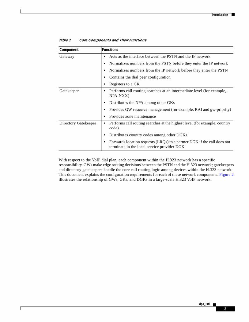
Table 1 summarizes the functions of the network core components.
DGK
GK
GWGW
LocalPSTN
VV
3787
7
Introduction
3dp3_isd
With respect to the VoIP dial plan, each component within the H.323 network has a specificresponsibility. GWs make edge routing decisions between the PSTN and the H.323 network; gatekeepersand directory gatekeepers handle the core call routing logic among devices within the H.323 network.This document explains the configuration requirements for each of these network components.Figure 2illustrates the relationship of GWs, GKs, and DGKs in a large-scale H.323 VoIP network.
Table 1 Core Components and Their Functions
Component Functions
Gateway • Acts as the interface between the PSTN and the IP network
• Normalizes numbers from the PSTN before they enter the IP network
• Normalizes numbers from the IP network before they enter the PSTN
• Contains the dial peer configuration
• Registers to a GK
Gatekeeper • Performs call routing searches at an intermediate level (for example,NPA-NXX)
• Distributes the NPA among other GKs
• Provides GW resource management (for example, RAI and gw-priority)
• Provides zone maintenance
Directory Gatekeeper • Performs call routing searches at the highest level (for example, countrycode)
• Distributes country codes among other DGKs
• Forwards location requests (LRQs) to a partner DGK if the call does notterminate in the local service provider DGK
Introduction
4dp3_isd
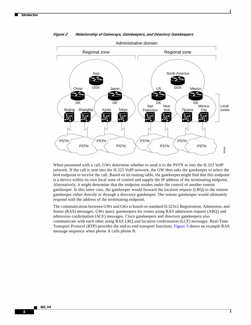
Figure 2 Relationship of Gateways, Gatekeepers, and Directory Gatekeepers
When presented with a call, GWs determine whether to send it to the PSTN or into the H.323 VoIPnetwork. If the call is sent into the H.323 VoIP network, the GW then asks the gatekeeper to select thebest endpoint to receive the call. Based on its routing table, the gatekeeper might find that this endpointis a device within its own local zone of control and supply the IP address of the terminating endpoint.Alternatively, it might determine that the endpoint resides under the control of another remotegatekeeper. In this latter case, the gatekeeper would forward the location request (LRQ) to the remotegatekeeper either directly or through a directory gatekeeper. The remote gatekeeper would ultimatelyrespond with the address of the terminating endpoint.
The communication between GWs and GKs is based on standard H.323v2 Registration, Admission, andStatus (RAS) messages. GWs query gatekeepers for routes using RAS admission request (ARQ) andadmission confirmation (ACF) messages. Cisco gatekeepers and directory gatekeepers alsocommunicate with each other using RAS LRQ and location confirmation (LCF) messages. Real-TimeTransport Protocol (RTP) provides the end-to-end transport functions.Figure 3shows an example RASmessage sequence when phone A calls phone B.
DGK
Asia
DGK
North America
Regional zone Regional zone
V V
GK
PSTN
PSTN
China
Beijing Shanghai
6046
4
V V
GK
PSTN
PSTN
Japan
Kyoto Tokyo
V V
GK
PSTN
PSTN
US
SanFrancisco
NewYork
V V
GK
PSTN
PSTN
Mexico
TijuanaMexico
CityLocalzones
Administrative domain

Design Methodology for Large-Scale Dial Plans
5dp3_isd
Figure 3 Example of RAS Messaging When Phone A Calls Phone B
Overview of the Dial PlanThe dial plan is the method by which individual blocks of telephone numbers (technically, E.164addresses) are assigned to physical facilities, or circuits. For large-scale service provider networks, dialplans consist of the following elements:
• A grouping of E.164 prefixes with respect to zones and zone GKs
• An assignment of E.164 address blocks to POPs and POP GWs
• The normalization (number translation, prefixing, and digit stripping) of telephone numbers at thePOP GWs
• The establishment of POTS and VoIP dial peers at the GWs
POTS dial peers define the phone numbers or prefixes of attached telephony devices, and the VoIP dialpeers define the IP address of the remote device (H.323 GW, GK, or endpoint) that is connected toremote phone numbers. POTS dial peers will always point to a voice port on the router, and thedestination of a VoIP dial peer will always be the IP address of a device that can terminate the VoIP call.
Design Methodology for Large-Scale Dial PlansIt is important to apply some basic design principles when designing a large-scale dial plan. Designoptions in this document will consider the principles described in the following sections:
• Dial Plan Distribution, page 6
• Hierarchical Design, page 6
• Simplicity in Provisioning, page 7
• Reduction in Postdial Delay, page 17
• Availability and Fault Tolerance, page 19
6046
5
DGK
LRQ
ARQ ACF ARQ ACF
LRQ
DGK
GK
GatewayA
Phone A Phone B
GatewayB
H.225 Fast start setup
LRQ
LCF
H.225 Fast start alerting / connect
RTP
GK
V V

Design Methodology for Large-Scale Dial Plans
6dp3_isd
Dial Plan DistributionGood dial plan architecture relies on effectively distributing the dial plan logic among the GW and GKcomponents. Isolating H.323 devices to a specific portion of the dial plan reduces the complexity of theconfiguration. Each component can focus on accomplishing specific tasks. Generally, local POP-specificdetails are handled at the local GW; higher-level routing decisions are passed along to the GKs andDGKs. A well-designed network places the majority of the dial plan logic at the GK and DGK devices.
Hierarchical DesignStrive to keep the majority of the dial plan logic (routing decision-making and failover) at the highestcomponent level. The DGK is generally considered the highest-level device. By maintaining ahierarchical design, you make the addition and deletion of zones more manageable. For example, scalingof the overall network is much easier when configuration changes need be to made to only a single DGKand a single zone GK instead of all the zone GKs.
Use a tiered architecture approach, using GWs, GKs, and DGKs. Security, redundancy, and networkmanagement are implemented after you take the following steps:
1. Determine your dial plan coverage areas. A GK (instead of a DGK) could cover one country code,for example.
2. Analyze and logically group the components to determine what area(s) each component will beresponsible for: a country code, an area code, or several prefixes, for example.
3. At the GW level, logically group the GWs into POPs. (Generally, POPs are situated in the highestdensity coverage areas: major cities, for example.)
4. Determine how many gateways you need by doing the following:
a. Measure the busy hour traffic (BHT). (Design the network for the peak-hour volume.)
b. Determine the number of DS-0s that you need to handle the BHT.
c. Determine how many GWs you need to service the DS-0s.
d. Understand the calls-per-second performance and DS-0 capacity of the selected GW platform.
Note GWs have different DS-0 capacities; a Cisco 5400 router has the capacity for many moreDS-0s than does a Cisco 5300, for example. The number of GWs needed also dependson the processing capability of the selected GW platform. A Cisco 5400 has more DS-0capacity and more processing capability (than a Cisco 5300), so it would use more GKresources than a Cisco 5300. You would need to provision fewer Cisco 5400 routers at aPOP than you would Cisco 5300 routers.
5. Logically separate the POPs into zones. A zone can have one or many POPs.
6. At the GK level, determine which GKs should administer which zones. A GK is used to group GWsinto logical zones of control, and perform all call routing between the zones.
The number of GKs you need depends on GW capacity and traffic load. The number of GKs per POPor POPs per GK depends on how many GWs are used. For example, 35 GWs in 1 POP could be 1zone, requiring one GK; 4 POPs with 4 GWs each might function adequately with one GKadministering the 16 GWs.
7. At the DGK level, determine which DGKs should administer which GKs. See step 3.

Design Methodology for Large-Scale Dial Plans
7dp3_isd
8. Consider that your DGKs (your highest level component) will exchange LRQs with other DGKs,acting as a demarcation point between separate carriers.
Simplicity in ProvisioningYou should keep the dial plan on the GWs and GKs as simple and symmetrical as possible whendesigning a network. Try to keep consistent dial plans on the GWs by using translation rules tomanipulate the local digit dialing patterns. These number patterns can be normalized into a standardformat or pattern before the digits enter the VoIP core. Putting digits into a standard format simplifiesGK zone prefix provisioning and GW dial peer management.
This methodology helps reduce the number of dial peer configurations on the outgoing POTS interface.If the GK can be provisioned to direct only calls of a certain area code to a particular GW, then you wouldnot need to provision all of the individual GWs with their respective area codes. Instead, you might beable to generalize the GW configurations. By normalizing the number, you also reduce the zone prefixsearch length, reducing the time required to search for a zone prefix match. For example, if you have the0118943xxxx digit pattern, you can send the number as 8943xxxx and have the GK search on 89 asopposed to 01189.
Number Normalization and Translation Rules
Gateway dial plan configurations focus on local PSTN access information for the edge of the H.323network. These dial plan configurations include defining which E.164 prefixes are supported by thePSTN connections of the GW. In large-scale service provider designs, you might rely on the GW toperform digit manipulation, whereby the GW takes a calling (or called) number and strips or adds(prefixes) digits before sending the number to its destination. The process of formatting the number to apredefined pattern is callednumber normalization.
Figure 4 illustrates an example of number normalization from the PSTN to the VoIP core. Digitmanipulation can be configured on the incoming POTS port or the outgoing VoIP dial peer to format a7-, 10-, 11-, or x-digit pattern into a fixed 10-digit pattern (United States-centric). The result is a numberthat has been normalized when it enters the VoIP cloud.
Figure 4 Number Normalization from PSTN to VoIP
6046
6PSTN VoIP
GK
VUser may dial 7,10, 11, or x digits
Number normalized:(for example, country+city+local)
Call direction
Number manipulation on incomingPOTS port:
Reduce VoIP dial peer complexityRoute all incoming PSTN calls to theVoIP cloud (for example, by using 1 or 001)Accommodate varying dialing strings and place in standard format (for example, local versus long distance)
Number manipulation on outgoing VoIP dial peer:Number normalization (for example,
country+city+local)Strip regional access number

Design Methodology for Large-Scale Dial Plans
8dp3_isd
Translation Rules
The GW uses the Cisco IOS translation rules to accomplish digit manipulation. Translation rules can beconfigured on the GW physical port or on a VoIP dial peer, as shown in the following example:
translation-rule 1Rule 0 ^0111.% 1Rule 1 ^0112.% 2Rule 2 ^0113.% 3Rule 3 ^0114.% 4Rule 4 ^0115.% 5Rule 5 ^0116.% 6Rule 6 ^0117.% 7Rule 7 ^0118.% 8Rule 8 ^0119.% 9
!dial-peer voice 1 voip
destination-pattern 011Ttranslate-outgoing called 1session target ras
!
The preceding translation rule matches digit patterns that begin with 0111 through 0119 and translatesthis 4-digit pattern into a single digit from 1 to 9, while preserving the remaining digits included in thedigit pattern. This process effectively strips the 011 (a common international access code) and sends theremaining digits to the VoIP gatekeeper for call routing.
You can use translation rules to manipulate both automatic number identification (ANI) and dialednumber identification service (DNIS) numbers. The following dial peer configuration commands can beused to match the ANI or DNIS of a call:
• answer-address
• destination-pattern
• incoming called-number
• numbering-type
You can test your translation rules by using thetest translation-rule command.
The GW can perform number manipulation when calls come into the GW from the VoIP network. In thiscase, the dial peer on the POTS port can either strip or add digits when sending numbers out to the PSTN.Figure 5 depicts number normalization from the VoIP network to the PSTN.
Figure 5 Number Normalization from VoIP Back to PSTN
6046
7
PSTN VoIP
GK
VMay dial as local number,long distance number, and so on
Destination number is normalized:(for example, country+city+local)
Call direction
Number manipulation on outgoing POTS port: Administer local PSTN access rules(for example, prefix or strip digits)

Design Methodology for Large-Scale Dial Plans
9dp3_isd
The following example of a POTS dial peer shows how the Cisco IOSprefix command can be used toadd digits to a calling number:
dial-peer voice 20 potsdestination-pattern 510.......prefix 1510
The precedingprefix command substitutes 1510 for the 510 and effectively adds a 1 to any 10-digitpattern that begins with 510.
Number Normalization for an International Dial Plan Example
Suppose you are a service provider that provides VoIP transport for calls originating from the San Josearea (408 area code). San Jose subscribers use the following digit patterns when making calls:
• For local calls within the San Jose area code: use a 7-digit number, for example, 555-1000
• For long distance calls within the United States: use an 11-digit number, for example,1-212-555-1000
• For international calls: use a 011 access code, a country code, an area code, and the number, forexample, 011-33-10-1111-2222
Suppose you want long distance calls to go through the VoIP network, but local calls to go back throughthe PSTN. The GK should always be queried to make this call routing decision. In this case, ARQs fromthe GW to the GK should be in the standard format:
country code + city (or area) code + local number
regardless of whether the user dialed 7 digits (local call), 11 digits (long distance call), or aninternational call with a 011 access code. You will need to configure the GW to normalize these patterns.The number normalization logic is shown inFigure 6.
Figure 6 Number Normalization Logic
In the following configuration example, translation rules are applied to perform the numbernormalization:
Hostname SJC-GW!translation-rule 2 Rule 0 ^2...... 14082
PSTN VoIP
GK
V Country+area+local33 10 111122221 212 365 10001 408 527 1000
Call direction
Number manipulation on outgoingVoIP dial peers:
For international calls, strip the access code (011)For long distance within US, different area code, keep same format.For local 7-digit calls, add the country code+area code (1 408).
InternationalLD in USLocal
6050
8
011 33 10 1111 22221 212 365 1000
527 1000

Design Methodology for Large-Scale Dial Plans
10dp3_isd
Rule 1 ^3...... 14083 Rule 2 ^4...... 14084 Rule 3 ^5...... 14085 Rule 4 ^6...... 14086 Rule 5 ^7...... 14087 Rule 6 ^8...... 14088 Rule 7 ^9...... 14089!translation-rule 1 Rule 0 ^0111.% 1 Rule 1 ^0112.% 2 Rule 2 ^0113.% 3 Rule 3 ^0114.% 4 Rule 4 ^0115.% 5 Rule 5 ^0116.% 6 Rule 6 ^0117.% 7 Rule 7 ^0118.% 8 Rule 8 ^0119.% 9!interface Ethernet0/0 ip address 172.19.49.166 255.255.255.192 h323-gateway voip interface h323-gateway voip id NA-GK ipaddr 172.19.49.168 1719 h323-gateway voip h323-id US-GW1!ip classlessip route 0.0.0.0 0.0.0.0 172.19.49.129no ip http server!voice-port 1/0/0!voice-port 1/0/1!dial-peer voice 1408 pots destination-pattern 14085551000 port 1/0/0!dial-peer voice 1 voip destination-pattern 011T translate-outgoing called 1 session target ras!dial-peer voice 2 voip destination-pattern 1T session target ras!dial-peer voice 3 voip destination-pattern [2-9]T translate-outgoing called 2 session target ras!gateway!
The following bullets summarize how number normalization works in the preceding example:
• For international calls, strip the access code
Translation rule 1 strips the 011 access code on numbers that begin with 011. The translation rule isapplied to dial peer 1, which matches all numbers beginning with 011 (that is, 011T). The “T” actsas a wildcard withinterdigit timeout; the digits will be collected when the user does not enter aDTMF tone within a certain time. The default value for this timeout is 10 seconds, and is

Design Methodology for Large-Scale Dial Plans
11dp3_isd
configurable (in seconds) on the voice port. (See the “Interdigit Timeout” section.) The user can alsoenter a termination character (#) after entering the full digit string, to indicate that digits are to becollected.
• For local 7-digit calls, add the country code + area code (1 408)
Translation rule 2 takes any 7-digit number that begins with 2 through 9 and adds a 1408 prefix tothat number, where 1 is the country code and 408 is the local area code. This translation rule isapplied to dial peer 3, which matches any digit pattern that begins with 2 through 9.
• For long distance calls within the United States (different area code), keep the same format
No translation rule is necessary for this case because the digit pattern is already in the desiredformat. Dial peer 2 is configured with no translation rule applied.
Interdigit Timeout
When the “T” timeout indicator is used at the end of the destination pattern in an outboundvoice-network dial peer, the router accepts the specified digits and then waits for an unspecified numberof additional digits. The router can collect up to 31 additional digits, as long as the interdigit timeouttimer has not expired. When the interdigit timeout timer expires, the router places the call.
The default value for the interdigit timeout is 10 seconds. With this setting, all digits will be collected10 seconds after the last digit is dialed. For example, if you dial 9195556789, but pause for 11 secondsbetween digits 8 and 9, only 919555678 will be collected by the GW. You can change the interdigittimeout value using thetimeouts interdigit command in voice-port configuration mode.
Note that unless the # character is used as a terminator at the end of thedestination-pattern command,the T-indicator by default adds 10 seconds to each call setup because the call is not attempted until thetimer expires. We recommend therefore that you reduce the interdigit timeout value if you usevariable-length dial plans, to reduce postdial delay.
The calling party can immediately terminate the interdigit timeout timer by entering the # characterwhile the router is waiting for additional digits. However, if the # character is entered as part of thefixed-length destination pattern that is entered before the router begins waiting for additional digits, it istreated as a dialed digit and is sent across the network when the digits are collected. For example, if thedestination pattern is configured as 2222…T, the entire string of 2222#99 is collected. But if the dialedstring is 2222#99#99, the #99 at the end of the dialed digits is not collected because the final # characteris treated as the dial-peer terminator command.
Dial Peer Preference Command and Failover Options
You can configure failover options on the GW by using multiple dial peers with thepreferencecommand. Thepreference command allows the GW to select a desired dial peer first, and then, if theGW receives an admission reject (ARJ) message from the GK, the GW selects the nextpreferred dialpeer. The default preference value is 0, which is the highest priority. For example, preference 2 is ahigher priority than preference 3.
This configuration is commonly referred to as arotary dial peer. This configuration is useful in caseswhere you want to perform some failover functionality—if the first GW dial peer is not able to resolvethe termination, then the next preferred dial peer is used. See the section “Use of Translation Rules,Technology Prefixes, and Dial Peer Failover Example” for an example of failover functionality.
In the following sample configuration, preference commands are configured on two dial peers; dial peer1 is tried first, then dial peer 2:
dial-peer voice 1 voipdestination-pattern 1408.......session target raspreference 1

Design Methodology for Large-Scale Dial Plans
12dp3_isd
!dial-peer voice 2 voip
destination-pattern 1408.......session target osppreference 2
Technology Prefixes
Technology prefixes allow special characters to be included in the called number. These specialcharacters are most commonly designated as 1#, 2#, 3#, and so on, and can be configured to prepend thecalled number on the outgoing VoIP dial peer. The GK can then check its GW technology prefix tablefor GWs that have registered with that particular technology prefix. Technology prefixes can also be usedto identify a type, class, or pool of GWs.
Technology prefix commands can be entered on both GWs and GKs in two places, depending on howyou want to design the technology prefix decision intelligence: the GW VoIP interface, or the GW dialpeer.
Technology Prefix on the Gateway VoIP Interface
To realize the advantages of the routing efficiencies that technology prefixes provide, the GW needs toidentify itself with a technology prefix number, such as 1#, 2#, and so on. This prefix number can beconfigured on the VoIP interface of the GW, as shown in the following example. Here the GWs registertheir technology prefix with a registration request (RRQ) message to the gatekeeper. This technologyprefix registration determines the GK selection of a GW for an incoming call.
hostname gw1!interface Ethernet0/0
ip address 10.1.1.1 255.255.255.0h323-gateway voip tech-prefix 2#
In this example, GW1 registers to the GK with 2# as the technology prefix. This technology prefixregistration determines which GW the GK selects for an incoming call.
You can display this registration on the GK with theshow gatekeeper gw-type-prefix command:
vn-gk# show gatekeeper gw-type-prefix
GATEWAY TYPE PREFIX TABLE=========================Prefix: 2#*
Zone vn-gk master gateway list:10.71.3.101:1720 gw1
Technology Prefix on the Gateway Dial Peer
You can configure a technology prefix on a specific VoIP dial peer using the following commands:
dial-peer voice 1 voipdestination-pattern 1408.......session target rastech-prefix 2#
The preceding commands prepend a 2# to the 1408……. called number. A called number of 5554000then becomes 2#14085554000.

Design Methodology for Large-Scale Dial Plans
13dp3_isd
When a call comes in, the GK first looks for a technology prefix match; then it tries to find a zone prefixmatch. It must find a GW that is registered with that zone prefix and that also matches the zone prefixtable. If these two matches occur, then the GK will direct the call to thategress gateway.
The following example shows how to configure the technology prefix and how to display it on the GK,along with the technology prefixes that have been registered:
hostname vn-gw1!interface Ethernet0 ip address 10.71.3.101 255.255.255.0 h323-gateway voip interface h323-gateway voip id vn-gk ipaddr 10.71.3.201 1719 h323-gateway voip h323-id vn-gw1 h323-gateway voip tech-prefix 1#!hostname vn-gw2!interface Ethernet0/0 ip address 10.71.3.105 255.255.255.0 h323-gateway voip interface h323-gateway voip id vn-gk ipaddr 10.71.3.201 1719 h323-gateway voip h323-id vn-gw2 h323-gateway voip tech-prefix 2#!hostname vn-gk!gatekeeper zone local vn-gk cisco.com 10.71.3.201 zone remote k-gk cisco.com 10.71.3.200 1719 zone remote hopoff cisco.com 10.71.3.202 1719 zone prefix vn-gk 1212* zone prefix k-gk 1212*! no shutdown
vn-gk# show gatekeeper gw-type-prefixGATEWAY TYPE PREFIX TABLE=========================Prefix: 2#*
Zone vn-gk master gateway list:10.71.3.101:1720 vn-gw1
Prefix: 1#*Zone vn-gk master gateway list:
10.71.3.105:1720 12125557777
The GK now has vn-gw1 (10.71.3.101) registered with the 1# prefix, and will consider this GW ifincoming calls arrive with a 1# prepended to the DNIS. Vn-gw2 is registered with the 2# prefix.
Note To be placed into the GW selection table on the GK, Cisco Trunking GWs must be configured toregister with a technology prefix of 1#. Analog GWs register their full E.164 address, so they do notneed to register a technology prefix to the GK.
Technology Prefix Commands on the Gatekeeper
The technology prefix commands described in the following sections are available on the GK to allowadditional call control.

Design Methodology for Large-Scale Dial Plans
14dp3_isd
Default Technology Prefix
The following commands configure a default technology prefix on the GK:
gatekeepergw-type-prefix 1# default-technology
If no technology prefixes are sent with the called number, this configuration tells the GK to use GWsthat are registered with 1#.
Forward LRQ to Hopoff Zone
The following commands configure the GK to receive a particular technology prefix and then forwardan LRQ message to the hopoff zone:
gatekeeper gw-type-prefix 7# hopoff spacezone
After receiving a called number with 7# preceding it, the device sends an LRQ message to the spacezoneGK. The spacezone hopoff GK takes priority over other GW selections.
Static Technology Prefix
The following commands configure the GK with a static technology prefix:
gatekeeper gw-type-prefix 8# gw ipaddr 10.1.1.1
This configuration creates a static entry into the GW type prefix table on the GK. It is the equivalent ofhaving a GW (IP address 10.1.1.1) register with an 8#.
Gatekeeper Technology Prefix Commands Example
The following example shows use of the technology prefix commands discussed in the precedingsections:
gatekeepergw-type-prefix 7#* hopoff spacezonegw-type-prefix 1#* default-technologygw-type-prefix 8#* gw ipaddr 10.1.1.1 1720
vn-gk# show gatekeeper gw-type-prefix
GATEWAY TYPE PREFIX TABLE=========================
Prefix: 7#* (Hopoff zone spacezone)Zone vn-gk master gateway list:
10.71.3.101:1720 vn-gw1
Prefix: 1#* (Default gateway-technology)Zone vn-gk master gateway list:
10.71.3.105:1720 12125557777 (Here, 10.71.3.105 GW has registered with a 1#,so it belongs to the 1# pool)
Prefix: 8#*Statically-configured gateways: (Not necessarily currently registered)
10.1.1.1:1720
Figure 7 shows technology prefix configurations.Figure 8 shows the use of technology prefixes in anetwork.

Design Methodology for Large-Scale Dial Plans
15dp3_isd
Figure 7 Technology Prefix Configurations
Figure 8 Use of Technology Prefixes in a Network
Note Normally, when an endpoint or GW sends an ARQ message to its GK, the GK resolves thedestination address by first looking for the technology prefix. When the technology prefix is matched,then the GK compares the remaining string against known zone prefixes. If the address resolves to a
Tech prefix database-dynamic
Table of tech prefixes registered by active GWs
Tech prefix database-static
gw-type-prefix 8# gw ipaddr x.y.z.bgw-type-prefix 7# hopoff spacezonegw-type-prefix 1# default-technology
interface Ethernet0/0h323-gateway voip tech-prefix 2#
EastGK
Tech prefix prepended to dialed number
dial-peer voice 100 voip tech-prefix 2#
WestGW1
EastGW1
6047
160
472
GK
GK
Spacezone hopoff
SFGW
Westernzone
2#4153451111
4153451111
V
PSTN 415
V
SFGW registers as 2#
interface ethernet0 h323-gateway voip tech-prefix 2#
dial-peer 100 destination-pattern 415..... session target ras tech-prefix 2#

Design Methodology for Large-Scale Dial Plans
16dp3_isd
remote zone, then the entire address, including both the technology and zone prefixes, is sent to theremote GK in an LRQ message. That remote GK then uses the technology prefix to decide which ofits GWs to hop off of. You can override this behavior by associating aforced hopoff zone with aparticular technology prefix. This association forces the call to the specified zone, regardless of thezone prefix in the address.
Zone Prefixes
A zone prefixis the part of a called number that identifies the zone where a call hops off. The zone prefixusually comprises the numbering plan area (NPA), known also as the area code, or the NPA-NXX (areacode and local office). Because there is no protocol by which gatekeepers can advertise which zoneprefixes can be accessed from their zones, these zone prefixes must be statically configured.
Zone prefixes are typically used to associate an area code or a set of area codes with a particularconfigured zone. First, local and remote zones are defined on the gatekeeper by the following commands:
gatekeeperzone local west-gk cisco.com 10.1.1.1zone remote east-gk cisco.com 10.1.1.2 1719zone remote central-gk cisco.com 10.1.1.3 1719
Then, the zone prefixes are configured on the GW to identify which GK manages remote area codes:
zone prefix east-gk 312.......zone prefix west-gk 408.......zone prefix central-gk 212*
Configuring zone prefixes is similar to configuring static routes in an IP environment. Note that currentlythere is no method for dynamically propagating dial plans to routers in a network. Therefore, you mustconfigure these static zone prefixes to let GKs know where they should forward LRQs to resolve the GWor endpoint IP address.
The purpose of a zone prefix on the GK is to associate an E.164 address to a particulartrunking gateway.Because the trunking GWs can terminate a range of addresses, the range must be manually defined onthe GK.
Another type of endpoint that can register with the GK is ananalog gatewayor H.323 endpoint. Thesedevices typically will register with the full E.164 address. In this case, the zone prefix is used to partitiona specific H.323 zone that will manage this set of addresses.
You can display the statically configured zone prefixes on the GK by using theshow gatekeeper zoneprefix command, as follows:
NA-GK# show gatekeeper zone prefix
ZONE PREFIX TABLE =================GK-NAME E164-PREFIX------- -----------east-gk 312.......west-gk 408.......Central-gk 212*
For a specific zone prefix (range of E.164 addresses), you can configure the GK to hand a call to aspecific GW, or pool of GWs, each at configured levels of priority. Note that only currently registeredGWs from the priority list will be considered by the GK. GWs that are too busy, as indicated by aresource availability indication (RAI) message, will be excluded from the selection.

Design Methodology for Large-Scale Dial Plans
17dp3_isd
You can specify GW priorities ranging from 10 (highest priority) to 0 (usage prohibited) for differentzone prefixes within a zone. GW priorities are implemented with thegw-pri command, as shown in thefollowing configuration example:
router-sj(config-gk)# zone local west-gk cisco.com 10.1.1.1router-sj(config-gk)# zone prefix west-gk 408....... gw-pri 10 gw408router-sj(config-gk)# zone prefix west-gk 415....... gw-pri 10 gw415router-sj(config-gk)# zone prefix west-gk 650....... gw-pri 10 gw650router-sj(config-gk)# zone prefix west-gk 510.......
All three GWs in the example can now register in the same zone. If a zone prefix has any defined GWpriorities, a separate GW list is kept for that zone prefix. The list contains all registered GWs, orderedby priority. When a GW is inserted in such a list, a default priority of 5 is used for unnamed GWs.
Zone prefixes that do not have any priorities defined (for example, the 510 area code in the precedingexample) do not have any special lists associated with them. Calls to the 510 area code will be servicedout of the master GW list for the zone.
With the preceding configuration, when gw408 registers, it is placed in the 408 list at priority 10, and inthe 415 and 650 lists at the default priority of 5. When all three GWs are registered, the zone list willlook like the following:
resultant Master listmaster list: gw408, gw415, gw650408 list: pri 10 gw408; pri 5 gw650, gw415415 list: pri 10 gw415; pri 5 gw650, gw408650 list: pri 10 gw650; pri 5 gw408, gw415
Any call to the 408 area code will be directed to gw408 because it has the highest priority. However, ifgw408 is busy (for example, it has sent an RAI message saying that it is almost out of resources), thecall will be routed to either gw415 or gw650. If you do not want either of these GWs to be used for 408calls, then you can specify that they have a zero priority for that area code as shown in the followingconfiguration:
router-sj(config-gk)# zone prefix west-gk 408....... gw-pri 10 gw408router-sj(config-gk)# zone prefix west-gk 408....... gw-pri 0 gw415 gw650
This configuration ensures that only gw408 will be used for calls to the 408 area code.
You should be aware that GW priority lists come with some overhead costs and that they should be usedwith discretion. If you can partition your zones to avoid using GW priorities, then you should do so. Ifyou must use this feature, try to keep the number of zone prefixes with priority definitions to fewer than50 per zone because any GW registering in a zone will need to be inserted into each prioritized list inthat zone, and removed from all the lists when it unregisters.
As we have seen, zone prefixes are created to identify particular area codes with zones that have beenestablished. Specific GWs within the zone can be prioritized so that the GK will hand off the call to thoseGWs first.
Reduction in Postdial DelayWhen you design a large-scale dial plan, you should consider the effects of postdial delay in the network.Postdial delay is the time from when the last digit is dialed to the moment the phone rings at the receivinglocation. GW and GK zone design, translation rules, and sequential LRQs all affect postdial delay. Striveto use these tools most efficiently to reduce postdial delay.

Design Methodology for Large-Scale Dial Plans
18dp3_isd
Hopoff Zones
Thehopoff zone refers to the point where a call makes the transition from H.323 to non-H.323 (forexample, PSTN or H.320) via a GW. You can configure a GK to administer a zone dedicated for servicingtraffic that is not local. For example, if phone A calls 3155559999, which is outside of the local areacodes defined by GK X, then a hopoff zone can be configured to handle such phone numbers. Think ofa hopoff zone as a default GW in the IP world.
The hopoff zone is used in conjunction with technology prefixes and is configured as an option with thegw-type-prefix command, as shown in the following example:
gatekeepergw-type-prefix 2# hopoff hopoffgk
This configuration is often referred to astechnology prefix forced hopoff. An example configuration isdepicted inFigure 9.
Figure 9 Application of the Hopoff Zone
GK GK
DGKGK
SFPOP
NYPOP
Westernzone
Easternzone
V
PSTN 415
Hopoffzone
V
LD carrier
V
PSTN 212
6047
3
gatekeeperzone remote hopoffgk cisco.com 10.50.99.1 1719gw-type-prefix 1# default-technologygw-type-prefix 2# hopoff hopoffgklrq forward-queries
DGK configuration
gatekeeperzone local westgk cisco.com 10.50.1.1 1719zone remote dgk cisco.com 10.50.1.100 1719gw-type-prefix 1# default-technologygw-type-prefix 2# hopoff dgk
WestGK configuration
interface loopback0h323-gateway voip tech-prefix 1#
dial-peer voice 1 voipdestination-pattern 1preference 0session target ras
dial-peer voice 2 voipdestination-pattern 1preference 1session target rastech-prefix 2#
SFGW configurationgatekeeper
zone local hopoffgk cisco.com10.50.99.1 1719
zone prefix hopoffgk*gw-type-prefix 2# default-tech
HopoffGK configuration
interface loopback0h323-gateway voip tech-prefix 2#
HopoffGW configuration

Design Methodology for Large-Scale Dial Plans
19dp3_isd
In Figure 9, a hopoff zone has been added, consisting of a hopoff GW and a hopoff GK. WestGK andDGK are configured with a static gw-type-prefix command. This command will cause all callednumbers with a 2# technology prefix to send an LRQ message to their next hopoff GK. In this case,WestGK will forward these LRQ messages to DGK, and DGK will forward them to HopoffGK.
Note that SFGW has been configured with two dial peers. Thepreferencecommand assigns the dial peerorder. This command is generally used for failover purposes when you have the same destination patternassigned to multiple dial peers.
Dial peer 1 first sends an ARQ message to WestGK to determine if it knows the called numberterminating GW address. If WestGK does not know the terminating GW address, then WestGK will sendan ARJ message to the GW. The second dial peer will then prepend a 2# technology prefix to the callednumber and again try an ARQ message to WestGK. This time, the 2# matches thegw-type-prefix 2#command to hop off to DGK. DGK also recognizes the 2# and matches itsgw-type-prefix 2#commandto hop off to HopoffGK. Note that the 2# gets propagated with the called number.
You can enter thehopoff keyword and gatekeeper ID multiple times in the same command to define agroup of GKs that will service a given technology prefix. Only one of the GKs in the hopoff list can belocal.
If the technology prefix does not have any forced zone attribute, the GK useszone prefix matching todetermine the zone. If the matching zone prefix is associated with a remote zone, an LRQ message issent to the remote GK. The LRQ message contains the entire called number, including the previouslystripped technology prefix. If the matching prefix is for a local zone, that zone is used to satisfy therequest.
If no zone prefix match is found, the default behavior is to attempt to use a local zone for hopoff ratherthan to fail the call. However, the default behavior might not be the desired behavior. You may preferthat an ARJ message be returned to the GW so that it can fall through to an alternate dial peer—forexample, one that specifies that the next hop is through a special-rate PSTN. To override the defaultbehavior, use thearq reject-unknown-prefix command in gatekeeper configuration mode.
Availability and Fault ToleranceDuring your dial plan design, you should consider overall network availability and call success rate.Fault tolerance and redundancy within H.323 networks are most important at the gatekeeper level. Useof an alternate GK, sequential LRQs, and Hot Standby Routing Protocol (HSRP) help provideredundancy and fault tolerance in the H.323 network. As of Cisco IOS Release 12.2, GK redundancy canbe configured for alternate GKs and HSRP for GKs.
Gatekeepers with HSRP
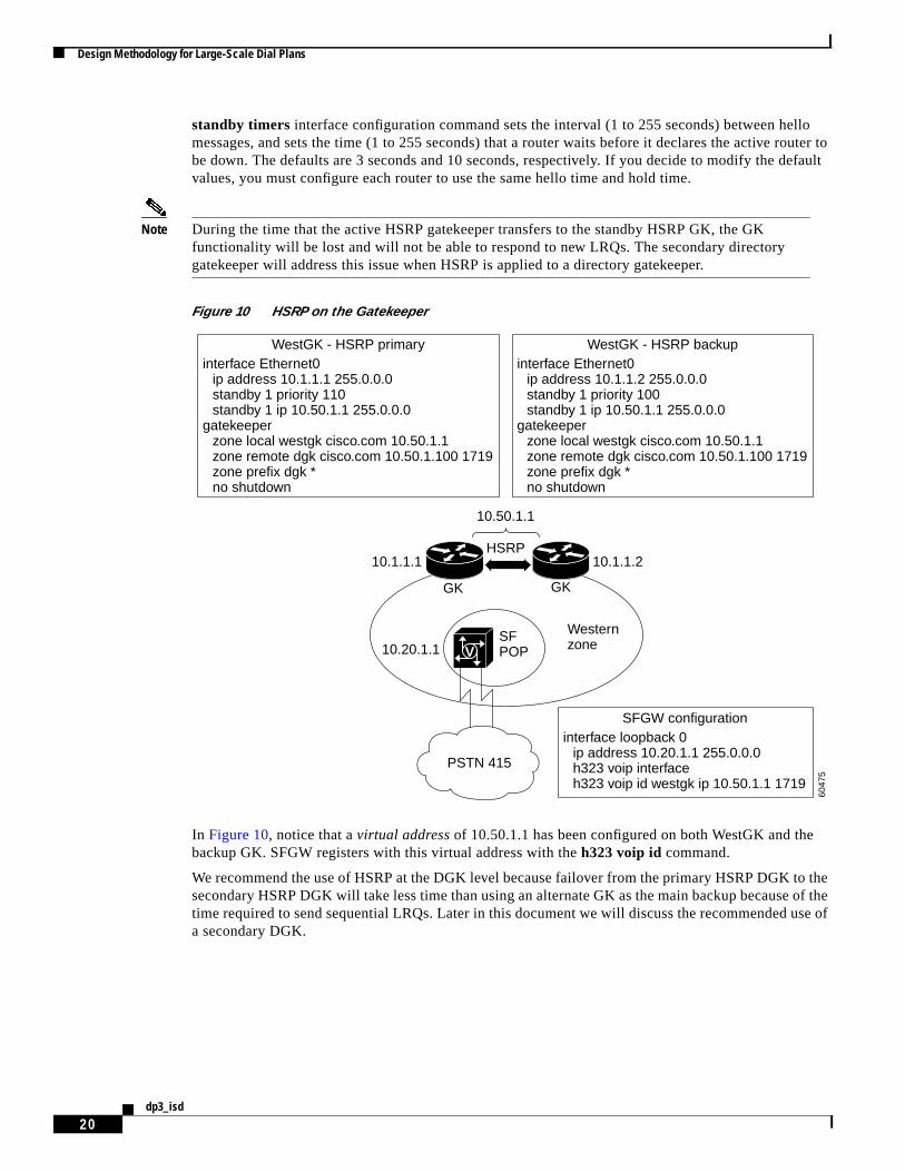
Because the GK maintains the majority of the call routing intelligence (zone prefix tables, technologyprefix tables, and E.164 registrations), the GK should be fault tolerant. You can configure GKs to useHSRP so that when one GK fails, the standby GK assumes its role, as shown inFigure 10.
Configure an active GK and a standby GK to be on the same subnet. Therefore, locate the GKs together.HSRP uses a priority scheme to determine which HSRP-configured router is the default active router. Toconfigure a router as the active router, you assign it a priority that is higher than the priority of the otherHSRP-configured router. The default priority is 100, so if you configure just one router to have a higherpriority, that router will be the default active router.
HSRP works by the exchange of multicast messages that advertise priority among HSRP-configuredrouters. When the active router fails to send a hello message within a configurable period, the standbyrouter with the highest priority becomes the active router after the expiration of a hold timer. The
Design Methodology for Large-Scale Dial Plans
20dp3_isd
standby timers interface configuration command sets the interval (1 to 255 seconds) between hellomessages, and sets the time (1 to 255 seconds) that a router waits before it declares the active router tobe down. The defaults are 3 seconds and 10 seconds, respectively. If you decide to modify the defaultvalues, you must configure each router to use the same hello time and hold time.
Note During the time that the active HSRP gatekeeper transfers to the standby HSRP GK, the GKfunctionality will be lost and will not be able to respond to new LRQs. The secondary directorygatekeeper will address this issue when HSRP is applied to a directory gatekeeper.
Figure 10 HSRP on the Gatekeeper
In Figure 10, notice that avirtual address of 10.50.1.1 has been configured on both WestGK and thebackup GK. SFGW registers with this virtual address with theh323 voip id command.
We recommend the use of HSRP at the DGK level because failover from the primary HSRP DGK to thesecondary HSRP DGK will take less time than using an alternate GK as the main backup because of thetime required to send sequential LRQs. Later in this document we will discuss the recommended use ofa secondary DGK.
6047
5
SFPOP
WesternzoneV
PSTN 415
interface Ethernet0ip address 10.1.1.1 255.0.0.0standby 1 priority 110standby 1 ip 10.50.1.1 255.0.0.0
gatekeeperzone local westgk cisco.com 10.50.1.1zone remote dgk cisco.com 10.50.1.100 1719zone prefix dgk *no shutdown
WestGK - HSRP primaryinterface Ethernet0
ip address 10.1.1.2 255.0.0.0standby 1 priority 100standby 1 ip 10.50.1.1 255.0.0.0
gatekeeperzone local westgk cisco.com 10.50.1.1zone remote dgk cisco.com 10.50.1.100 1719zone prefix dgk *no shutdown
WestGK - HSRP backup
interface loopback 0ip address 10.20.1.1 255.0.0.0h323 voip interfaceh323 voip id westgk ip 10.50.1.1 1719
SFGW configuration
10.50.1.1
HSRP
GK
10.1.1.210.1.1.1
10.20.1.1
GK

Design Methodology for Large-Scale Dial Plans
21dp3_isd
Alternate Gatekeepers
In a system where GKs are used, thealternate gatekeeper feature provides redundancy. Thisenhancement allows a GW to use up to two alternate GKs to provide a backup if the primary GK fails.More specifically, you can configure a GW to register with two GKs. If the first GK fails, the alternateGK can then be used for call routing, and will maintain call routing without call failure.
In the following example, the GW is configured to register with two GKs. The default priority is 127 (thelowest priority); 1 is the highest priority.
interface Ethernet 0/1ip address 172.18.193.59 255.255.255.0h323-gateway voip interfaceh323-gateway voip id GK1 ipaddr 172.18.193.65 1719 priority 120h323-gateway voip id GK2 ipaddr 172.18.193.66 1719h323-gateway voip h323-id cisco2
In this example, we have configured 172.18.193.65 to be the primary GK, and 172.18.193.66 as thesecondary GK.
In Figure 11, note that the configurations on WestGK and WestAltGK are very similar with respect totheir local and remote zones. Note that there is an entryzone prefix westaltgk 415* on WestGK andzone prefix westgk 415*on WestAltGK. These entries become necessary in the situation described asfollows.
Suppose you have two GWs at the SF POP that are both registered to WestGK (the primary gatekeeper).WestGK experiences a failure for 30 seconds, then becomes active again. During the 30-second failure,GW1 reregisters to WestAltGK because its 60-second RRQ timer expires. However, the GW2 RRQ timerdoes not expire within this time window and GW2 remains registered with WestGK. We then have a casewhere the GWs are registered to two different GKs. The extra zone prefix statement ensures that the GKwill check the adjacent GK for GWs that are not registered with it.

Design Methodology for Large-Scale Dial Plans
22dp3_isd
Figure 11 Alternate GK on the Zone GKs
Cisco IOS Release 12.2 introduced a feature that can send LRQs in a sequential fashion instead of in aunicast blast of LRQs. This is a significant advantage over HSRP because backup GKs no longer needto be located in the same geographic area.
Gatekeeper Clusters
Another way to provide GK redundancy and load sharing is to configure GKs in acluster. You can haveas many as five GKs in a cluster. Members of a GK cluster communicate with each other by usingGatekeeper Update Protocol (GUP), a Cisco proprietary protocol based on TCP.Figure 12 depicts fiveGKs in a cluster.
6047
6
SFPOP
WesternzoneV
PSTN 415
gatekeeperzone local westgk cisco.com 10.50.1.1 1719zone remote westaltgk cisco.com 10.50.1.2 1719zone remote dgk cisco.com 10.50.1.100 1719zone prefix westgk 415 gw-priority 10 sfgw1zone prefix westaltgk 415*zone prefix dgk *no shutdown
WestGK configurationgatekeeper
zone local westaltgk cisco.com 10.50.1.2 1719zone remote westgk cisco.com 10.50.1.1 1719zone remote dgk cisco.com 10.50.1.100 1719zone prefix westaltgk 415 gw-priority 10 sfgw1zone prefix westgk 415*zone prefix dgk *no shutdown
WestAltGK configuration
interface loopback 0ip address 10.20.1.1 255.0.0.0h323-gateway voip interfaceh323-gateway voip id westgk ipaddr 10.50.1.1 1719h323-gateway voip id westaltgk ipaddr 10.50.1.2 1719 priority 127
SFGW configuration
AltGK
10.50.1.210.50.1.1
10.20.1.1
GK

Design Methodology for Large-Scale Dial Plans
23dp3_isd
Figure 12 A Gatekeeper Cluster
Each GK in the cluster is configured to know the IP addresses of the member GKs. Upon boot-up, eachGK receives a gatekeeper request (GRQ) message from the other GKs. This GRQ message has thealternate GK information embedded in the nonstandard portion of the message. At this point, a GK in acluster opens a TCP connection with all other GKs in the cluster. GUP updates are sent by each GK at30-second intervals.
GUP Messages
The following messages are sent by GKs in a cluster:
• AnnouncementIndication—Sent periodically, every 30 seconds by default, by each member GK ofthe cluster. When a GK receives this message, it updates the information about call capacity,endpoint capacity, CPU load, memory usage, number of calls, and number of registered endpointsof the alternate GK (sender).
• AnnouncementReject—Sent when there is a configuration mismatch. The receiver will display theerror and terminate the GUP connection with the sender.
• RegistrationIndication—Sent when the GUP connection is made with a new alternate GK, or whena new endpoint registers with the GK.
• UnregistrationIndication—Sent when an endpoint is aged out or the GK is shut down, or when anendpoint unregisters with the GK.
• ResourceIndication—Sent when a GK receives an RAI message from the GW.
The GUP Protocol
GUP announcements inform other GKs about a GK memory and CPU utilization, number of endpointsregistered, and the used and available bandwidth. The memory and CPU utilization information helps inresource management of the cluster because at any given time any GK in the cluster has the load, CPU,memory, and call capacity information. If this GK is overloaded, it can ask the endpoint to use theresources of the alternate GK with the lowest load.
Each GK gets the registered endpoint information from all other GKs. Thus the information about anyendpoint, registered to any GK in a cluster, can be obtained from any member GK, which helps in LRQprocessing. Now any GK in the cluster can resolve the LRQ requests sent from an external GK.
When a new endpoint registers with a GK in a cluster, that GK sends a registrationIndication messageby GUP. Similarly, an unregistrationIndication message is sent when an endpoint unregisters. If a GK ina cluster does not send six consecutive GUP updates, it is marked as down by all member GKs.
When an endpoint informs a GK about a new call by an information request response (IRR) message,the GK increments the total number of active calls it is monitoring, and sends this data by GUP.
GK1
GK2
GUP
GK4
GK5
GK3
6524
8
Design Methodology for Large-Scale Dial Plans
24dp3_isd
If a GK fails due to a software exception or a power outage, the endpoints are load balanced. Loadbalancing is achieved during the initial registration confirmation (RCF) message. The initial RCFmessage contains a list of alternate GKs, listed in order of priority, to which the endpoint can try toregister if this (primary) GK does not respond to RAS messages.
When the primary GK fails to respond to registration request (RRQ) messages, the endpoint will thentry to register with other GKs in the cluster, in order of priority, as dictated in the RCF. As soon as theendpoint is registered, an information request (IRQ) message is sent by the GK to get the informationfor all calls currently in progress at the endpoint, ensuring that the call information is not lost becauseof an outage at the GK.
When a GK resources are overloaded (no more call capacity), it can redirect its endpoints to an alternateGK in the cluster that has sufficient resources. Redirecting endpoints is achieved by sending an ARJ orRRJ reject message in response to an ARQ or RRQ message. The ARJ or RRJ message contains the IPaddress of the alternate GK to be used. Upon the receipt of this message, the endpoint will then try toregister with the new alternate GK and proceed with new call processing.
Secondary Directory Gatekeeper
A secondary directory gatekeeper can be used to back up another directory gatekeeper by using thesequential LRQfeature. For example, if a zone GK sends an LRQ to a primary DGK and fails to receivean LCF, another (sequential) LRQ can be sent from the zone GK to this alternate GK. The secondaryDGK will then provide the normal DGK prefix lookup and call routing in the network until the primaryDGK is able to function again. We apply this design in the example inFigure 13.
Directory Gatekeeper Design Recommendations
We recommend that you use a combination of the alternate GK, HSRP DGK, and secondary DGK toprovide fault tolerance and redundancy in larger H.323 networks.Figure 13 illustrates the networktopology.

Design Methodology for Large-Scale Dial Plans
25dp3_isd
Figure 13 Fault-Tolerant Design Recommendation
In the network topology shown inFigure 13, fault tolerance and redundancy have been implemented asfollows:
• Alternate GK at the zone level
The GWs are configured to register to a primary GK and to an alternate GK in case the primary GKfails. At any given time, a GW might be registered to either its primary or its alternate GK. Toaccommodate zone fragmentation, you must configure sequential LRQs on the GKs and DGKsbecause Cisco GKs do not communicate registration states to each other.
• HSRP pair at the DGK level
HSRP is used to provide fault tolerance for the DGK. The HSRP failover time can be configured asspecified in the HSRP section of this document. A single virtual IP address is shared between thetwo HSRP DGKs. Zone GKs need only point to this virtual address.
• Secondary DGK at the DGK level
HSRP failover detection may take some time, during which no calls will be processed. To cover thiscase, you can configure the local GKs to point to an additional secondary DGK. Use of sequentialLRQs at the GK level is required. During this time, calls will still be completed, but with additionalpostdial delay. The alternate DGK is configured the same as the primary HSRP DGK pair (seemessages 2a and 2b later in this section).
10.50.1.1
HSRP
SequentialLRQs
GK
10.50.1.1
10.50.2.1
SequentialLRQs
DGK
10.50.1.2
Sequential LRQs
AlternateDGK
DGK
10.50.2.2
GK
2 1 2a 2b 1a 1b
SFPOP
NYPOP
Westernzone
EasternzoneV
PSTN 415
V
PSTN 212
6046
1
AlternateGK
AlternateGK

H.323 Network Components in Large-Scale Dial Plans
26dp3_isd
The following is the high-level failover flow for the topology shown inFigure 13. Assume that a user inthe SF POP calls 12125551000 at the NY POP.
1. LRQ is sent from WesternGK to DGK.
1a. LRQ is sent from DGK to EasternGK, with no response from EasternGK.
1b. LRQ is sent from DGK to EasternAltGK (sequential LRQ).
Either EasternGK or EasternAltGK will send the LCF back to WesternGK, depending on whether thereis a 1a or a 1b condition.
Suppose one of the DGKs fails. In this case, assume DGK1 is the primary and it experiences a failure.HSRP will function to activate the secondary, DGK2. Some time will elapse during this failover. Duringthis failover time, no new calls can be processed because neither DGK will respond. To provideredundancy for this interval, use a secondary DGK to receive the LRQ during this time.
The following is the call flow from the Western Zone to the Eastern Zone:
1. LRQ is sent from WesternGK to DGK; no response from DGK (HSRP failover interval).
2. Second LRQ is sent from WesternGK to AltDGK (sequential LRQ).
2a. LRQ is sent from AltDGK to EasternGK; no response from EasternGK.
2b. LRQ is sent from AltDGK to EasternAltGK.
Either the EasternGK or EasternAltGK will send the LCF back to the WesternGK, depending on whetherthere is a 2a or a 2b condition.
H.323 Network Components in Large-Scale Dial PlansThis section discusses the basic components of an H.323 network and some of the advanced Cisco IOScommands that can be used when large-scale service provider network dial plans are designed. Thesecomponents are gateways, gatekeepers, and directory gatekeepers.
Gateways in Large-Scale Dial PlansAs the interface between the PSTN and the IP network, a GW is responsible for edge routing decisions.The GW contains the dial peer configuration and normalizes numbers from the PSTN before they enterthe IP network, and normalizes numbers from the IP network before they enter the PSTN. The GWregisters to a GK for management of its resources by the exchange of RAS messages.
Gatekeepers in Large-Scale Dial PlansAs more VoIP gateways are added to the network, the administration of adding and changing dial peerson all remote VoIP GWs can become unmanageable. You can add a gatekeeper to thegateway-to-gateway network to provide centralized dial plan administration. Gatekeepers allow you tologically partition the network intozones and centrally manage the dial plan.
Note A zone is a collection of endpoints, gateways, or multipoint control units (MCUs) registered to asingle GK. A single Cisco IOS GK can control several zones. Think of a single GK controllingseveral zones as several logical GKs coexisting on a single router. The logical GK is identified by a

H.323 Network Components in Large-Scale Dial Plans
27dp3_isd
GK name, which is also the name of the zone. When a Cisco IOS GK is configured, any zonecontrolled by this router is referred to as alocal zone. Any zone controlled by a different router iscalled aremote zone.
Without the GK, explicit IP addresses for each terminating GW would need to be configured on theoriginating GW and matched to a VoIP dial peer. With the GK in place, the remote VoIP GWs simplyreference the dial plan on the GK when they are trying to establish VoIP calls with other remote VoIPGWs.
When a GK is added to the network, GWs will register to that GK in the form of an E.164 address, e-mailalias, or H.323 ID. The GK will then maintain the call routing information. GWs can query thisinformation in the RAS ARQ message by pointing the session target to theras keyword. Thisconfiguration reduces the number of dial peers necessary on the GW.
For each locally registered GW, the GK has information about which prefixes that GW supports. On theGK, these prefixes are statically defined using thezone prefixcommand. In the United States, area codesare typically represented by the zone prefix. In European countries, prefixes might be represented as acity or zone code. In addition to containing the local prefixes, the GK contains information about theprefixes supported by any remote GKs in the network. The GK is responsible for ultimately providingthe terminating GW address to the originating GW. This address can be a local resource, or the GK canquery any one of its remote GKs to supply a terminating GW address.
The GK needs to track routing calls that enter the IP cloud. This routing is typically done on E.164prefixes. The GK must track which GWs service which prefixes, and which prefixes reside on remoteGKs, and must maintain resource administration and GW registrations.
Figure 14 illustrates a gatekeeper-to-gatekeeper H.323 network with three GKs. Each GK manages azone and is responsible for administering calls to its dedicated zone. GWs reside within each zone andregister to their respective GKs by RAS messages.

H.323 Network Components in Large-Scale Dial Plans
28dp3_isd
Figure 14 Gatekeeper-to-Gatekeeper Network, Fully Meshed
A static zone prefix table has been configured on each of the GKs inFigure 14. Each GK is configuredwith the zone prefixes shown in the following configuration:
hostname WesternGK!gatekeeper
zone local WesternGK cisco.com 10.1.1.1zone remote CentralGK cisco.com 10.2.1.1 1719zone remote EasternGK cisco.com 10.3.1.1 1719zone prefix WesternGK 415* gw-priority 10 SFGWzone prefix CentralGK 312*zone prefix EasternGK 212*
!hostname CentralGK!gatekeeper
zone local CentralGK cisco.com 10.2.1.1zone remote WesternGK cisco.com 10.1.1.1 1719zone remote EasternGK cisco.com 10.3.1.1 1719zone prefix CentralGK 312* gw-priority 10 ChicagoGWzone prefix WesternGK 415*
GK GK
GK
SFPOP
NYPOP
Westernzone
Easternzone
V
PSTN 415
ChicagoPOP
Centralzone
V
PSTN 312
V
PSTN 212
6046
8
CentralGKRouting Table
Prefix
312415212
Destination
ChicagoGWWesternGKEasternGK
WesternGKRouting Table
Prefix
415312212
Destination
SFGWCentralGKEasternGK
EasternGKRouting Table
IP network
Prefix
212312415
Destination
NYGWCentralGKWesternGK
H.323 Network Components in Large-Scale Dial Plans
29dp3_isd
zone prefix EasternGK 212*!hostname EasternGK!gatekeeper
zone local EasternGK cisco.com 10.3.1.1zone remote CentralGK cisco.com 10.2.1.1 1719zone remote WesternGK cisco.com 10.1.1.1 1719zone prefix EasternGK 212* gw-priority 10 NYGWzone prefix CentralGK 312*zone prefix WesternGK 415*
!
Note Thezone prefixcommand is covered in more detail in the “Zone Prefixes” section of this document.
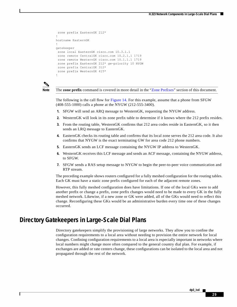
The following is the call flow forFigure 14. For this example, assume that a phone from SFGW(408-555-1000) calls a phone at the NYGW (212-555-3400).
1. SFGW will send an ARQ message to WesternGK, requesting the NYGW address.
2. WesternGK will look in its zone prefix table to determine if it knows where the 212 prefix resides.
3. From the routing table, WesternGK confirms that 212 area codes reside in EasternGK, so it thensends an LRQ message to EasternGK.
4. EasternGK checks its routing table and confirms that its local zone serves the 212 area code. It alsoconfirms that NYGW is the exact terminating GW for area code 212 phone numbers.
5. EasternGK sends an LCF message containing the NYGW IP address to WesternGK.
6. WesternGK receives this LCF message and sends an ACF message, containing the NYGW address,to SFGW.
7. SFGW sends a RAS setup message to NYGW to begin the peer-to-peer voice communication andRTP stream.
The preceding example shows routers configured for a fully meshed configuration for the routing tables.Each GK must have a static zone prefix configured for each of the adjacent remote zones.
However, this fully meshed configuration does have limitations. If one of the local GKs were to addanother prefix or change a prefix, zone prefix changes would need to be made to every GK in the fullymeshed network. Likewise, if a new zone or GK were added, all of the GKs would need to reflect thischange. Reconfiguring these GKs would be an administrative burden every time one of these changesoccurred.
Directory Gatekeepers in Large-Scale Dial PlansDirectory gatekeepers simplify the provisioning of large networks. They allow you to confine theconfiguration requirements to a local area without needing to provision the entire network for localchanges. Confining configuration requirements to a local area is especially important in networks wherelocal numbers might change more often compared to the general country dial plan. For example, ifexchanges are added or rate centers change, these configurations can be isolated to the local area and notpropagated through the rest of the network.

H.323 Network Components in Large-Scale Dial Plans
30dp3_isd
Figure 15shows the fully meshed network fromFigure 14with a DGK added. Notice that each local GKneeds to be configured only with its local information. The rest of the network is “star-routed” out of theDGK for resolution. This configuration allows the GKs to be aware of only their own local changes, andisolates the rest of the network from needing to cope with any local changes. The DGK is the only devicethat needs to know the overall dial plan.
The concept is similar to a Frame Relay WAN. Suppose you need to configure a fully meshed networkwith many dialer maps pointing to each of the adjacent routers in the cloud. By using the Frame Relayhub and spoke configuration, you can have all of the traffic flow through a hub router to get to theadjacent routers. You need only configure dialer maps to the hub router.
The same concept can be applied in H.323 networks with the introduction of the DGK. The DGK willbe the hub for the zone prefix routing tables. The remote GKs need to configure only their local zoneprefixes and a wildcard (*) default route to the DGK.
By adding the DGK, we have generated a hierarchical structure with the DGK as the highest levelcomponent. We are still able to achieve full connectivity, but with a minimum number of remote zoneentries on each of the GKs. The bulk of the remote zone configuration is performed on the DGK.
A large service provider network should be divided into various regions to support scaling issues withperformance and management. Each regional GK is responsible for maintaining GW registrations withinits region in addition to making the final routing decisions for the terminating and originating GWs. TheDGKs are responsible for interzone communication across GK regions and for selecting the proper zonein which to terminate the call.
In Figure 15, WesternGK knows of local area code 415, and EasternGK is responsible for its own areacode 212 within its local zone. Using zone prefix commands, a routing table is statically configured oneach GK. For area codes local to that particular GK, the actual GW can be configured to match the localarea code. For area codes that are remote (not within that GK), use a “star route” or a zone prefixwildcard (*) to the DGK. The DGK will now maintain the master zone prefix table.

H.323 Network Components in Large-Scale Dial Plans
31dp3_isd
Figure 15 Addition of a Directory Gatekeeper
The static zone prefix table on each of the GKs has been simplified fromFigure 14. The zone GKs andDGK are now configured as shown in the following configuration:
hostname WesternGK!gatekeeper
zone local WesternGK cisco.com 10.1.1.1zone remote DGK cisco.com 10.4.1.1 1719zone prefix WesternGK 415* gw-priority 10 SFGWzone prefix DGK *
!hostname CentralGK!gatekeeper
zone local CentralGK cisco.com 10.2.1.1zone remote DGK cisco.com 10.4.1.1 1719zone prefix CentralGK 312* gw-priority 10 ChicagoGWzone prefix DGK *
!hostname EasternGK!gatekeeper
zone local EasternGK cisco.com 10.3.1.1zone remote DGK cisco.com 10.4.1.1 1719zone prefix EasternGK 212* gw-priority 10 NYGWzone prefix DGK *
GK GK
DGKGK
SFPOP
NYPOP
Westernzone
Easternzone
V
PSTN 415
ChicagoPOP
Centralzone
V
PSTN 312
V
PSTN 212
6046
9
CentralGKRouting Table
Prefix
312*
Destination
ChicagoGWDGK
WesternGKRouting Table
Prefix
415*
Destination
SFGWDGK
EasternGKRouting Table
Prefix
212*
Destination
NYGWDGK
DGKRouting Table
Prefix
415312212
Destination
WesternGKCentralGKEasternGK
IP network

H.323 Network Components in Large-Scale Dial Plans
32dp3_isd
!hostname DGK!gatekeeper
zone local DGK cisco.com 10.4.1.1zone remote WesternGK cisco.com 10.1.1.1 1719zone remote CentralGK cisco.com 10.2.1.1 1719zone remote EasternGK cisco.com 10.3.1.1 1719zone prefix WesternGK 415*zone prefix CentralGK 312*zone prefix EasternGK 212*lrq forward-queries
To enable a GK to forward LRQ messages that contain E.164 addresses that match zone prefixescontrolled by remote GKs, use thelrq forward-queries command in gatekeeper configuration mode inthe gatekeeper configurations.
Directory Gatekeeper Performance
On average, the DGK requires 25 percent of the CPU needed by the local zone GKs. Therefore, if theCPU load on the GK is 40 percent, then you need only 10 percent CPU allocation on the DGK. CiscoIOS software has a limit of five recursive LRQs; an LRQ is limited to five hops. Local zones and LRQforwarding zones can be mixed.
Adding a New Zone and a New Rate Center Example
Suppose you are a service provider that provides VoIP transport for users in San Francisco, Chicago, andNew York. The business is growing and you want to design your dial plan to accommodate the followingchanges:
• Add a new region in the Mountain time zone to service area code 406.
• Add a new rate center in the San Francisco area.
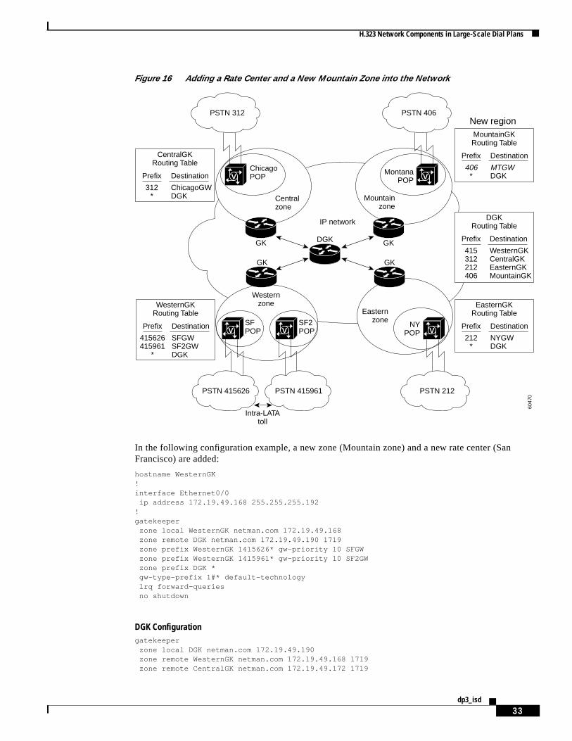
San Francisco has added a new set of local numbers in the 415 area code. However, toll charges in thePSTN are applied when callers with 415-626-xxxx numbers call subscribers with 415-961-xxxxnumbers. It is less expensive for users to use the VoIP transport than the PSTN when making these calls.Figure 16 depicts the addition of the new region and the new rate center.
H.323 Network Components in Large-Scale Dial Plans
33dp3_isd
Figure 16 Adding a Rate Center and a New Mountain Zone into the Network
In the following configuration example, a new zone (Mountain zone) and a new rate center (SanFrancisco) are added:
hostname WesternGK!interface Ethernet0/0
ip address 172.19.49.168 255.255.255.192!gatekeeper
zone local WesternGK netman.com 172.19.49.168zone remote DGK netman.com 172.19.49.190 1719zone prefix WesternGK 1415626* gw-priority 10 SFGWzone prefix WesternGK 1415961* gw-priority 10 SF2GWzone prefix DGK *gw-type-prefix 1#* default-technologylrq forward-queriesno shutdown
DGK Configurationgatekeeper
zone local DGK netman.com 172.19.49.190zone remote WesternGK netman.com 172.19.49.168 1719zone remote CentralGK netman.com 172.19.49.172 1719
GK GK
DGKGK
SFPOP
NYPOP
Westernzone
Easternzone
V
PSTN 415626
SF2POPV
PSTN 415961
Intra-LATAtoll
ChicagoPOP
Centralzone
V
PSTN 312
V
PSTN 212
6047
0
CentralGKRouting Table
Prefix
312*
Destination
ChicagoGWDGK
GK
New region
MontanaPOP
Mountainzone
V
PSTN 406
WesternGKRouting Table
Prefix
415626415961
*
Destination
SFGWSF2GWDGK
EasternGKRouting Table
Prefix
212*
Destination
NYGWDGK
MountainGKRouting Table
Prefix
406*
Destination
MTGWDGK
IP network DGKRouting Table
Prefix
415312212406
Destination
WesternGKCentralGKEasternGKMountainGK
Use of Translation Rules, Technology Prefixes, and Dial Peer Failover Example
34dp3_isd
zone remote EasternGK netman.com 172.19.49.176 1719zone remote MountainGK netman.com 172.19.49.200 1719zone prefix WesternGK 1415*zone prefix CentralGK 1312*zone prefix EasternGK 1212*zone prefix MountainGK 1406*lrq forward-queriesno shutdown
MountainGK Configurationhostname MountainGK!interface Ethernet0/0
ip address 172.19.49.200 255.255.255.192!!gatekeeper
zone local MountainGK netman.com 172.19.49.168zone remote DGK netman.com 172.19.49.190 1719zone prefix MountainGK 1496* gw-priority 10 MTGWzone prefix DGK *gw-type-prefix 1#* default-technologylrq forward-queriesno shutdown
Use of Translation Rules, Technology Prefixes, and Dial PeerFailover Example
This example demonstrates the use of Cisco IOS tools and features to provide better call-routing controlwith hierarchical design, and to minimize dial peer configuration.Figure 17 illustrates the topology ofthe example network.

Use of Translation Rules, Technology Prefixes, and Dial Peer Failover Example
35dp3_isd
Figure 17 Example Network Using Failover Scenarios
Business CaseIn this example, the service provider has two GWs that serve both the 408555* and the 408777*NPA-NXX zones. The GK has two local zones, twilight and hopoff.
Calls from GWA to GWB should be made through the gatekeeper VoIP network. However, if GWB isunavailable because of failure or a resource allocation issue, you should make the following provisions:
• Calls to 408555* should be hairpinned back through the PSTN (GWA POTS) and completed to thedestination. These calls through the PSTN do not incur any intra-LATA toll charges.
• Calls to 408777* should be sent through to the hopoff zone, not to the PSTN. There is an intra-LATAtoll charge associated with these calls, so the customer wants to redirect these calls to the hopoffzone, which has a better rate.
Cisco IOS ToolsThe following tools are used in this example:
• Translation rules: Use translation rules to strip or add a 1 to the calling number to allow additionalcall-routing control in the GW selection order.
• Preference command: Use thepreference command on dial peers to allow a dial peer selectionorder. For instance, the gateway will match first on dial peer 1. If the GW receives a location reject(LRJ) message from the GK, the next preferred dial peer will be used. Use of thepreferencecommand will allow for failover scenarios and greater call control.
• Technology prefixes: Use technology prefixes to allow certain dial peers to use a hopoff zonetechnology prefix (that is, 27#). When dial peer failover occurs, the 27# technology prefix will forcethe call to go to the hopoff zone.
GK
Intra-LATA
GWAV
PSTN408555*408777*
GWB V
PSTN408555*408777*
V
CarrierHopoff GW
Zonehopoff
Zonetwilight
6047
4
Use of Translation Rules, Technology Prefixes, and Dial Peer Failover Example
36dp3_isd
• Hopoff zone: Create a hopoff zone and a hopoff GW within the network. This zone has a specialnegotiated rate for VoIP calls, so the calls cost less than those going through the PSTN.
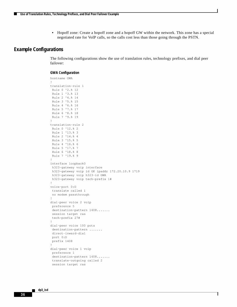
Example Configurations
The following configurations show the use of translation rules, technology prefixes, and dial peerfailover:
GWA Configurationhostname GWA!translation-rule 1
Rule 0 ^2.% 12Rule 1 ^3.% 13Rule 2 ^4.% 14Rule 3 ^5.% 15Rule 4 ^6.% 16Rule 5 ^7.% 17Rule 6 ^8.% 18Rule 7 ^9.% 19
!translation-rule 2
Rule 0 ^12.% 2Rule 1 ^13.% 3Rule 2 ^14.% 4Rule 3 ^15.% 5Rule 4 ^16.% 6Rule 5 ^17.% 7Rule 6 ^18.% 8Rule 7 ^19.% 9
!interface loopback0
h323-gateway voip interfaceh323-gateway voip id GK ipaddr 172.20.10.9 1719h323-gateway voip h323-id GWAh323-gateway voip tech-prefix 1#
!voice-port 0:D
translate called 1no modem passthrough
!dial-peer voice 2 voip
preference 5destination-pattern 1408.......session target rastech-prefix 27#
!dial-peer voice 100 pots
destination-pattern .......direct-inward-dialport 0:Dprefix 1408
!dial-peer voice 1 voip
preference 1destination-pattern 1408.......translate-outgoing called 2session target ras

Use of Translation Rules, Technology Prefixes, and Dial Peer Failover Example
37dp3_isd
GWB Configurationhostname GWB!interface loopback0
h323-gateway voip interfaceh323-gateway voip id GK ipaddr 172.20.10.9 1719h323-gateway voip h323-id GWBh323-gateway voip tech-prefix 1#
Hopoff GW Configurationhostname hopoff-gw!interface loopback0
h323-gateway voip interfaceh323-gateway voip id GK ipaddr 172.20.10.9 1719h323-gateway voip h323-id hopoff-gw
GK Configurationhostname GK!gatekeeper
zone local twilight-zone cisco.com 172.20.10.10zone local hopoff-zone cisco.comzone prefix twilight-zone 408555* gw-priority 10 GWBzone prefix twilight-zone 408555* gw-priority 5 GWAzone prefix twilight-zone 408777* gw-priority 10 GWBzone prefix twilight-zone 408777* gw-priority 0 GWAzone prefix hopoff-zone 1408777* gw-priority 10 hopoff-gwgw-type-prefix 1#* default-technologygw-type-prefix 27#* hopoff hopoff-zoneno shutdown
GK# show gatekeeper gw-type-prefix
GATEWAY TYPE PREFIX TABLE=========================Prefix: 1#* (Default gateway-technology)
Zone twilight-zone master gateway list:172.20.10.3:1720 GWA172.20.10.5:1720 GWB
Zone twilight-zone prefix 408777* priority gateway list(s):Priority 10:
172.20.10.5:1720 GWBZone twilight-zone prefix 408555* priority gateway list(s):
Priority 10:172.20.10.5:1720 GWB
Priority 5:172.20.10.3:1720 GWA
Prefix: 27#* (Hopoff zone hopoff-zone)Zone hopoff-zone master gateway list:
172.20.10.4:1720 hopoff-gwZone hopoff-zone prefix 1408777* priority gateway list(s):
Priority 10:172.20.10.4:1720 hopoff-gw
Use of Translation Rules, Technology Prefixes, and Dial Peer Failover Example
38dp3_isd
Configuration Review and Dial Plan LogicThis section shows the following flows:
• GWA calls 1408555* on GWB—Success
• GWA calls 1408555* on GWB—Failover through zone prefixes
• GWA calls 1408777* on GWB—Success
• GWA calls 1408777* on GWB—Failover using dial peer failover (preference command)
Flow 1: Success
GWA calls 1408555* on GWB:
1. Voice-port translation rule 1 adds 1 to the NPA.
2. Match dial peer 1 translation rule 2, which strips the digit 1. Send an ARQ message to the GK.
3. Match zone prefix twilight-zone 408555* gw-priority 10 GWB.
The call is successful through VoIP.
Flow 2: Failover Through Zone Prefixes
GWA calls 1408555* on GWB:
1. Voice-port translation rule 1 adds 1 to the NPA.
2. Match dial peer 1 translation rule 2, which strips the digit 1. Send an ARQ message to the GK.
3. Match zone prefix twilight-zone 408555* gw-priority 10 GWB.
4. GWB is down (or RAI unavailable), so GWB is removed from the GK selection table. Look for thenext match.
5. Match zone prefix twilight-zone 408555* gw-priority 5 GWA.
6. Select GWA (itself).
7. Match on POTS dial peer, and destination pattern …….
8. Hairpin the call back through the PSTN.
The call is successful through the PSTN.
Flow 3: Success
GWA calls 1408777* on GWB:
1. Voice-port translation rule 1 adds 1 to the NPA.
2. Match dial peer 1 translation rule 2, which strips the digit 1. Send an ARQ message to the GK.
3. Match zone prefix twilight-zone 408777* gw-priority 10 GWB.
The call is successful through VoIP.

Implementing an International Dial Plan Example
39dp3_isd
Flow 4: Failover Using Dial Peer Failover (preference Command)
GWA calls 1408777* on GWB:
1. Voice-port translation rule 1 adds 1 to the NPA.
2. Match dial peer 1 translation rule 2, which strips the digit 1. Send an ARQ message to the GK.
3. Match zone prefix twilight-zone 408777* gw-priority 10 GWB.
4. GWB is down (or RAI unavailable), so GWB is removed from the GK selection table. Look for thenext match.
5. Match, but zone prefix twilight-zone 408777* gw-priority 0 GWA.
6. The GK sends an ARJ message to GWA.
7. Roll over to next preferred dial peer, dial peer 2.
8. Dial peer 2 does not strip the 1 (no translation rule) but does add a technology prefix of 27#,resulting in the number 27#14087771000.
9. GWA sends an ARQ message to the GK.
10. Match the gw-type-prefix 27#* hopoff hopoff-zone.
11. Match the zone prefix hopoff-zone 1408777* gw-priority 10 hopoff-gw.
12. In an ACF message, the GK sends the hopoff-gw address to GWA.
The call is successful to the hopoff GW.
Implementing an International Dial Plan ExampleThis implementation provides an example of an international dialing plan using several of the methodscovered to reduce dial peer configuration at the GW, simplify prefix searches at the GK, and provide faulttolerance at the GK and the DGK level.Figure 18 depicts the topology of the example network.

Implementing an International Dial Plan Example
40dp3_isd
Figure 18 Topology of an International Service Provider Network
The service provider wants to provide wholesale voice services with a presence in North America, Asia,and EMEA. You need to design and configure a gateway, gatekeeper, and directory gatekeeper H.323network that will provide for the following POP locations:
• North America—the GW is in the United States
• Asia—the GW is in China
• EMEA—the GW is in France
The design goals of the network are as follows:
• Successful intercarrier calls between countries
• Hierarchical GW, GK, DGK design
• Number normalization into the VoIP from the PSTN
• Fault tolerance at the GK and DGK level
Figure 19 shows an example topology with these design goals implemented.
GK
Intra-LATA
Toll North America Asia EMEA
DGK
GK GK
US-GW1V
Ratecenter #1
China-GW1
V
PSTN
France-GW1
V
PSTN
US-GW2 V
Ratecenter #2
6047
9
1*US-GK86* AS-GK33* E-GK
1408527.... US-GW11408779.... US-GW2* DGK
8610* China-GW1*DGK
3303* France-GW1*DGK
• Add the Asia zone• Add the EMEA zone• Add directory gatekeeper

Implementing an International Dial Plan Example
41dp3_isd
Figure 19 Network Topology with Country-Specific Calling Information
To accomplish the design goals of the network, implement the design strategies described in thefollowing sections:
• Number Normalization to Reduce the Number of Dial Peers on the Gateway
• Directory Gatekeeper and Local Zone Prefix Search
• Alternate Gatekeepers and HSRP Pairs for Fault Tolerance
Number Normalization to Reduce the Number of Dial Peers on the GatewayTo reduce the number of GW dial peers, create translation rules on each GW to accommodate the localcountry dialing habits.
US Gateways
The setup includes the following elements:
• Two GWs are located in the US POP.
• US-GW1 has phone 14085271000.
DGK(primary)
.178
.168
172.19.48.128/26
172.19.49.166
14085271000
.179
.169
172.19.49.167 172.19.49.170 172.19.49.174
14087791000 861011112222 330311112222
NA-GK NA-AltGK
.172 .173 .176 .177
AS-GK AS-AltGK E-GK
US-GW1
Phone
USCountry code = 1Area code = 408International
access code = 011
ChinaCountry code = 86Local zone = 10International
access code = 00
FranceCountry code = 33Local zone = 03International
access code = 00
Phone Phone Phone
US-GW2 China-GW1 France-GW1
E-AltGK
.184
DGK2(secondary)
HSRP virtual address
ALT-DGK
North America zone Asia zone EMEA zone
.190
6048
0

Implementing an International Dial Plan Example
42dp3_isd
• US-GW2 has phone 14087791000.
The local dialing habits in the United States are as follows:
• For local numbers in the 408 area code, use 7-digit dialing.
• For long distance numbers within the United States, use 1 + area code + local number.
• For international numbers (outside of North America), use 011 (access code) + country code + localcity code + local number.
Normalize these numbers into the following formula:
country code + city code + local number
China Gateway
The setup for China is as follows:
• One GW is located in the China POP.
• The country code = 86, the local city code = 010.
• CHINA-GW1 has phone 861011112222.
The local dialing habits in China are as follows:
• For local numbers in the 010 city code, use 8-digit dialing, beginning with digits1 to 9.
• For long distance numbers within China, use the area code (dialed with 0x or 0xx) + local number.
• For international numbers (outside of China), use 00 (access code) + country code + local city code+ local number.
Normalize these numbers into the following formula:
country code + city code + local number
France Gateway
The setup for France is as follows:
• One GW is located in the France POP.
• The country code = 33, the local city code = 03.
• FRANCE-GW1 has phone 330311112222.
The local dialing habits in France are as follows:
• For local numbers in the 03 area code, use the area code (0x) + 8-digit dialing.
• For long distance numbers within France, use the area code (dialed with 0x) + 8-digit local number.
• For international numbers (outside of France), use 00 (access code) + country code + local city code+ local number.
Normalize these numbers into the following formula:
country code + city code + local number
The translation rules should be configured to match the local dialing habits within the country in whichthe GW resides. Match the translation rule with the appropriate outgoing VoIP dial peer.
Implementing an International Dial Plan Example
43dp3_isd
Directory Gatekeeper and Local Zone Prefix SearchGatekeepers are configured to administer their local country zones and city or area codes (for example,8610*) to their specific GWs. A DGK is used to handle call routing on just the country code number.This hierarchical functionality is possible because the GK applies translation rules to present thiscountry code first, before it enters the VoIP gatekeeper core. In addition, zone prefix tables on the zoneGKs are greatly simplified because the DGK has been designed in.
Alternate Gatekeepers and HSRP Pairs for Fault ToleranceAlternate gatekeepers are configured at the zone GK level to back up the primary GKs. A primary andsecondary HSRP pair is used at the DGK level to back up each other. A secondary DGK is used to backup the DGK pair.
Note The configurations for the alternate GK in the US POP are shown. The configurations for thealternate GK in the Asia and France POPs are not shown.
Configuration ListingsThe following are the configurations for implementing the international dial plan:
US-GW1 ConfigurationCurrent configuration:!! No configuration change since last restart!version 12.1service timestamps debug uptimeservice timestamps log uptimeno service password-encryption!hostname US-GW1!enable password xxx!username cisco password 0 xxx!clock timezone PDT -7ip subnet-zerono ip domain-lookup!translation-rule 2 Rule 0 ^2...... 14082 Rule 1 ^3...... 14083 Rule 2 ^4...... 14084 Rule 3 ^5...... 14085 Rule 4 ^6...... 14086 Rule 5 ^7...... 14087 Rule 6 ^8...... 14088 Rule 7 ^9...... 14089!translation-rule 1 Rule 0 ^0111.% 1 Rule 1 ^0112.% 2

Implementing an International Dial Plan Example
44dp3_isd
Rule 2 ^0113.% 3 Rule 3 ^0114.% 4 Rule 4 ^0115.% 5 Rule 5 ^0116.% 6 Rule 6 ^0117.% 7 Rule 7 ^0118.% 8 Rule 8 ^0119.% 9!interface Ethernet0/0 ip address 172.19.49.166 255.255.255.192 h323-gateway voip interface h323-gateway voip id NA-GK ipaddr 172.19.49.168 1719 priority 1 h323-gateway voip id NA-ALTGK ipaddr 172.19.49.169 1719 priority 2 h323-gateway voip h323-id US-GW1 h323-gateway voip tech-prefix 1#!ip classlessip route 0.0.0.0 0.0.0.0 172.19.49.129no ip http server!voice-port 1/0/0 timeouts interdigit 3!voice-port 1/0/1!dial-peer cor custom!dial-peer voice 1408 pots destination-pattern 14085271000 port 1/0/0!dial-peer voice 1 voip destination-pattern 011T translate-outgoing called 1 session target ras!dial-peer voice 4 voip destination-pattern [2-9]...... translate-outgoing called 2 session target ras!dial-peer voice 99 voip destination-pattern 2601 session target ipv4:172.19.49.4!dial-peer voice 2 voip destination-pattern 1T session target ras!gateway!line con 0 transport input noneline aux 0line vty 0 4 exec-timeout 0 0 password xxx!end
US-GW2 ConfigurationCurrent configuration:!

Implementing an International Dial Plan Example
45dp3_isd
version 12.1service timestamps debug uptimeservice timestamps log uptimeno service password-encryption!hostname US-GW2!enable password xxx!username cisco password 0 xxx!ip subnet-zerono ip domain-lookup!call rsvp-sync!translation-rule 1 Rule 0 ^0111.% 1 Rule 1 ^0112.% 2 Rule 2 ^0113.% 3 Rule 3 ^0114.% 4 Rule 4 ^0115.% 5 Rule 5 ^0116.% 6 Rule 6 ^0117.% 7 Rule 7 ^0118.% 8 Rule 8 ^0119.% 9!translation-rule 4 Rule 0 ^2...... 14082 Rule 1 ^3...... 14083 Rule 2 ^4...... 14084 Rule 3 ^5...... 14085 Rule 4 ^6...... 14086 Rule 5 ^7...... 14087 Rule 6 ^8...... 14088 Rule 7 ^9...... 14089!interface Ethernet0/0 ip address 172.19.49.167 255.255.255.192 h323-gateway voip interface h323-gateway voip id NA-GK ipaddr 172.19.49.168 1719 priority 1 h323-gateway voip id NA-ALTGK ipaddr 172.19.49.169 1719 priority 2 h323-gateway voip h323-id US-GW2!ip classlessip route 0.0.0.0 0.0.0.0 172.19.49.129no ip http server!voice-port 1/0/0!voice-port 1/0/1!dial-peer cor custom!dial-peer voice 1 voip destination-pattern 011T translate-outgoing called 1 session target ras!dial-peer voice 2 voip destination-pattern 1T session target ras!dial-peer voice 1408 pots
Implementing an International Dial Plan Example
46dp3_isd
destination-pattern 14087791000 port 1/0/0!dial-peer voice 4 voip destination-pattern [2-9]...... translate-outgoing called 4 session target ras!gateway!line con 0 transport input noneline aux 0line vty 0 4 exec-timeout 0 0 password xxx!end
China-GW1 ConfigurationCurrent configuration:!version 12.1service timestamps debug uptimeservice timestamps log uptimeno service password-encryption!hostname CHINA-GW1!username cisco password 0 xxx!ip subnet-zerono ip domain-lookup!translation-rule 2 Rule 0 ^01.% 8601 Rule 1 ^02.% 8602 Rule 2 ^03.% 8603 Rule 3 ^04.% 8604 Rule 4 ^05.% 8605 Rule 5 ^06.% 8606 Rule 6 ^07.% 8607 Rule 7 ^08.% 8608 Rule 8 ^09.% 8609!translation-rule 1 Rule 0 ^001.% 1 Rule 1 ^002.% 2 Rule 2 ^003.% 3 Rule 3 ^004.% 4 Rule 4 ^005.% 5 Rule 5 ^006.% 6 Rule 6 ^007.% 7 Rule 7 ^008.% 8 Rule 8 ^009.% 9!interface Ethernet0/0 ip address 172.19.49.170 255.255.255.192 h323-gateway voip interface h323-gateway voip id AS-GK ipaddr 172.19.49.172 1719 h323-gateway voip h323-id CHINA-GW1 h323-gateway voip tech-prefix 1#!
Implementing an International Dial Plan Example
47dp3_isd
interface Ethernet0/1 no ip address shutdown!ip classlessip route 0.0.0.0 0.0.0.0 172.19.49.129no ip http server!voice-port 1/0/0 timeouts interdigit 3!voice-port 1/0/1!dial-peer cor custom!dial-peer voice 1 voip destination-pattern 00T translate-outgoing called 1 session target ras!dial-peer voice 2 voip destination-pattern 86T session target ras!dial-peer voice 3 voip destination-pattern 0[1-9]T translate-outgoing called 2 session target ras!dial-peer voice 8610 pots destination-pattern 861011112222 port 1/0/0!gateway!line con 0 transport input noneline aux 0line vty 0 4 exec-timeout 0 0 password xxx!end
France-GW1 ConfigurationCurrent configuration:!version 12.1service timestamps debug uptimeservice timestamps log uptimeno service password-encryption!hostname FRANCE-GW1!no logging consoleenable password xxx!username cisco password 0 xxx!ip subnet-zerono ip domain-lookup!call rsvp-sync

Implementing an International Dial Plan Example
48dp3_isd
!dial-control-mib retain-timer 60dial-control-mib max-size 1200!translation-rule 2 Rule 0 ^01.% 3301 Rule 1 ^02.% 3302 Rule 2 ^03.% 3303 Rule 3 ^04.% 3304 Rule 4 ^05.% 3305 Rule 5 ^06.% 3306!translation-rule 1 Rule 0 ^0011.% 1 Rule 1 ^0012.% 2 Rule 2 ^0013.% 3 Rule 3 ^0014.% 4 Rule 4 ^0015.% 5 Rule 5 ^0016.% 6 Rule 6 ^0017.% 7 Rule 7 ^0018.% 8 Rule 8 ^0019.% 9!translation-rule 3 Rule 0 ^001.% 1 Rule 1 ^002.% 2 Rule 2 ^003.% 3 Rule 3 ^004.% 4 Rule 4 ^005.% 5 Rule 5 ^006.% 6 Rule 6 ^007.% 7 Rule 7 ^008.% 8 Rule 8 ^009.% 9!interface Ethernet0/0 ip address 172.19.49.174 255.255.255.192 h323-gateway voip interface h323-gateway voip id E-GK ipaddr 172.19.49.176 1719 h323-gateway voip h323-id FRANCE-GW1 h323-gateway voip tech-prefix 1#!interface Ethernet0/1 no ip address shutdown!ip classlessip route 0.0.0.0 0.0.0.0 172.19.49.129no ip http server!voice-port 1/0/0 timeouts interdigit 3!voice-port 1/0/1!voice-port 1/1/0!voice-port 1/1/1!dial-peer cor custom!dial-peer voice 3301 pots destination-pattern 330311112222 port 1/0/0!

Implementing an International Dial Plan Example
49dp3_isd
dial-peer voice 1 voip destination-pattern 00T translate-outgoing called 3 session target ras!dial-peer voice 2 voip destination-pattern 0[1-6]........ translate-outgoing called 2 session target ras!gateway!line con 0 transport input noneline aux 0line vty 0 4 exec-timeout 0 0 password xxx login local!no scheduler allocateend
NA-GK (North America Gatekeeper) ConfigurationCurrent configuration:!version 12.1service timestamps debug uptimeservice timestamps log uptimeno service password-encryption!hostname NA-GK!no logging consoleenable password xxx!username cisco password 0 xxx!ip subnet-zerono ip domain-lookup!dial-control-mib retain-timer 60dial-control-mib max-size 1200!interface Ethernet0/0 ip address 172.19.49.168 255.255.255.192!interface Ethernet0/1 no ip address shutdown!ip classlessip route 0.0.0.0 0.0.0.0 172.19.49.129no ip http server!snmp-server engineID local 0000000902000001969C63E0snmp-server community public RWsnmp-server packetsize 4096!dial-peer cor custom!gatekeeper zone local NA-GK netman.com 172.19.49.168
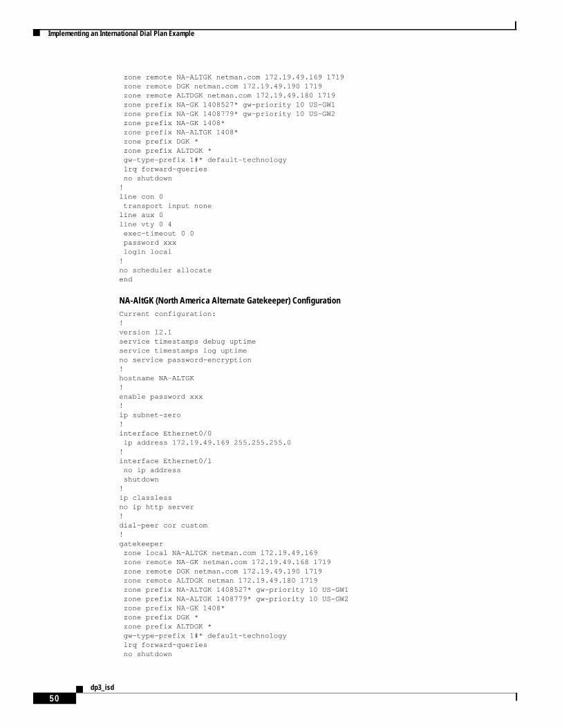
Implementing an International Dial Plan Example
50dp3_isd
zone remote NA-ALTGK netman.com 172.19.49.169 1719 zone remote DGK netman.com 172.19.49.190 1719 zone remote ALTDGK netman.com 172.19.49.180 1719 zone prefix NA-GK 1408527* gw-priority 10 US-GW1 zone prefix NA-GK 1408779* gw-priority 10 US-GW2 zone prefix NA-GK 1408* zone prefix NA-ALTGK 1408* zone prefix DGK * zone prefix ALTDGK * gw-type-prefix 1#* default-technology lrq forward-queries no shutdown!line con 0 transport input noneline aux 0line vty 0 4 exec-timeout 0 0 password xxx login local!no scheduler allocateend
NA-AltGK (North America Alternate Gatekeeper) ConfigurationCurrent configuration:!version 12.1service timestamps debug uptimeservice timestamps log uptimeno service password-encryption!hostname NA-ALTGK!enable password xxx!ip subnet-zero!interface Ethernet0/0 ip address 172.19.49.169 255.255.255.0!interface Ethernet0/1 no ip address shutdown!ip classlessno ip http server!dial-peer cor custom!gatekeeper zone local NA-ALTGK netman.com 172.19.49.169 zone remote NA-GK netman.com 172.19.49.168 1719 zone remote DGK netman.com 172.19.49.190 1719 zone remote ALTDGK netman 172.19.49.180 1719 zone prefix NA-ALTGK 1408527* gw-priority 10 US-GW1 zone prefix NA-ALTGK 1408779* gw-priority 10 US-GW2 zone prefix NA-GK 1408* zone prefix DGK * zone prefix ALTDGK * gw-type-prefix 1#* default-technology lrq forward-queries no shutdown

Implementing an International Dial Plan Example
51dp3_isd
!line con 0 transport input noneline aux 0line vty 0 4 password xxx login!end
AS-GK (Asia Gatekeeper) ConfigurationCurrent configuration:!version 12.1service timestamps debug uptimeservice timestamps log uptimeno service password-encryption!hostname AS-GK!no logging consoleenable password xxx!username cisco password 0 xxx!ip subnet-zerono ip domain-lookup!interface Ethernet0/0 ip address 172.19.49.172 255.255.255.192!interface Ethernet0/1 no ip address shutdown!ip classlessip route 0.0.0.0 0.0.0.0 172.19.49.129no ip http server!snmp-server engineID local 0000000902000001969C63A0snmp-server community public RW!dial-peer cor custom!gatekeeper zone local AS-GK netman.com 172.19.49.172 zone remote DGK netman.com 172.19.49.190 1719 zone remote ALTDGK netman.com 172.19.49.184 1719 zone prefix AS-GK 8610* gw-priority 10 CHINA-GW1 zone prefix DGK * zone prefix ALTDGK * no shutdown!line con 0 transport input noneline aux 0line vty 0 4 exec-timeout 0 0 password xxx login local!no scheduler allocateend

Implementing an International Dial Plan Example
52dp3_isd
E-GK (EMEA Gatekeeper) ConfigurationCurrent configuration:!version 12.1service timestamps debug uptimeservice timestamps log uptimeno service password-encryption!hostname E-GK!no logging consoleenable password xxx!username cisco password 0 xxx!clock timezone PDT -7ip subnet-zerono ip domain-lookup!interface Ethernet0/0 ip address 172.19.49.176 255.255.255.192!interface Ethernet0/1 no ip address shutdown!ip classlessip route 0.0.0.0 0.0.0.0 172.19.49.129no ip http server!snmp-server engineID local 00000009020000024B8FEF60snmp-server community public RW!dial-peer cor custom!gatekeeper zone local E-GK netman.com 172.19.49.176 zone remote DGK netman.com 172.19.49.190 1719 zone remote ALTDGK netman.com 172.19.49.180 1719 zone prefix E-GK 3303* gw-priority 10 FRANCE-GW1 zone prefix DGK * zone prefix ALTDGK * no shutdown!line con 0 transport input noneline aux 0line vty 0 4 exec-timeout 0 0 password xxx login local!ntp clock-period 17207746ntp server 172.19.49.166no scheduler allocateend
DGK (Directory Gatekeeper—Primary HSRP) ConfigurationCurrent configuration:!version 12.1service timestamps debug uptime

Implementing an International Dial Plan Example
53dp3_isd
service timestamps log uptimeno service password-encryption!hostname DGK!enable password xxx!ip subnet-zero!interface FastEthernet0/0 ip address 172.19.49.178 255.255.255.192 duplex auto speed auto standby 1 priority 110 standby 1 ip 172.19.49.190!interface FastEthernet0/1 no ip address duplex auto speed auto!no ip classlessip route 0.0.0.0 0.0.0.0 172.19.49.129no ip http server!dial-peer cor custom!gatekeeper zone local DGK netman.com 172.19.49.190 zone remote NA-GK netman.com 172.19.49.168 1719 zone remote AS-GK netman.com 172.19.49.172 1719 zone remote E-GK netman.com 172.19.49.176 1719 zone remote NA-AGK netman.com 172.19.49.169 1719 zone prefix NA-GK 1* zone prefix E-GK 33* zone prefix AS-GK 86* lrq forward-queries no shutdown!line con 0 transport input noneline aux 0line vty 0 4 password xxx login
DGK2 (Directory Gatekeeper—Secondary HSRP) ConfigurationCurrent configuration:!version 12.1service timestamps debug uptimeservice timestamps log uptimeno service password-encryption!hostname DGK2!boot system flash c3640-ix-mz.121-2.T.binenable password xxx!ip subnet-zero!interface FastEthernet0/0 ip address 172.19.49.179 255.255.255.192

Implementing an International Dial Plan Example
54dp3_isd
no ip redirects duplex auto speed auto standby 1 ip 172.19.49.190!interface FastEthernet0/1 no ip address shutdown duplex auto speed auto!no ip classlessno ip http server!gatekeeper zone local DGK netman.com 172.19.49.190 zone remote NA-GK netman.com 172.19.49.168 1719 zone remote AS-GK netman.com 172.19.49.172 1719 zone remote E-GK netman.com 172.19.49.176 1719 zone remote NA-AGK netman.com 172.19.49.169 1719 zone prefix NA-GK 1* zone prefix E-GK 33* zone prefix AS-GK 86* lrq forward-queries no shutdown!line con 0 transport input noneline aux 0line vty 0 4 password xxx login!end
ALT-DGK (Secondary Directory Gatekeeper) ConfigurationCurrent configuration:!version 12.1service timestamps debug uptimeservice timestamps log uptimeno service password-encryption!hostname ALT-DGK!boot system flash c3640-ix-mz.121-2.T.binenable password xxx!ip subnet-zerono ip domain-lookup!interface FastEthernet0/0 ip address 172.19.49.184 255.255.255.192 duplex auto speed auto!interface FastEthernet0/1 no ip address shutdown duplex auto speed auto!no ip classless
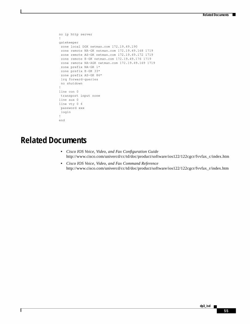
Related Documents
55dp3_isd
no ip http server!gatekeeper zone local DGK netman.com 172.19.49.190 zone remote NA-GK netman.com 172.19.49.168 1719 zone remote AS-GK netman.com 172.19.49.172 1719 zone remote E-GK netman.com 172.19.49.176 1719 zone remote NA-AGK netman.com 172.19.49.169 1719 zone prefix NA-GK 1* zone prefix E-GK 33* zone prefix AS-GK 86* lrq forward-queries no shutdown!line con 0 transport input noneline aux 0line vty 0 4 password xxx login!end
Related Documents• Cisco IOS Voice, Video, and Fax Configuration Guide
http://www.cisco.com/univercd/cc/td/doc/product/software/ios122/122cgcr/fvvfax_c/index.htm
• Cisco IOS Voice, Video, and Fax Command Referencehttp://www.cisco.com/univercd/cc/td/doc/product/software/ios122/122cgcr/fvvfax_r/index.htm

Related Documents
56dp3_isd