designing a visual scripting system
TRANSCRIPT

Supervisors: Jakob Thomsen Dr. Christoph Minnameier Submitted: 7. February 2015
Designing a Visual Scripting System
Thesis submitted for the academic degree Bachelor of Science (B.Sc.) Gamedesign
Submitted by: David N. Lehn
GD1011


Abstract
Visual scripting systems are powerful tools that allow users to easily create high-level application logic without the use of a textual programming language. While there are a large number of specialized solutions available for different areas of application (e.g. defining AI routines in games or creating image processing algorithms), truly general-purpose solutions are suspiciously absent. The aim of this paper is to establish a theoretical foundation for building such a general-purpose visual scripting system, by examining the design aspects of several established systems. Based on this, an ideal design for a simple, flexible and robust visual scripting language and environment will be devised, which will then be used to create a practical implementation in C++. The implementation will be built in a way that allows it to be extended, customized and adapted to arbitrary purposes, allowing easy integration of visual scripting elements into other applications. Finally, the scripting language will be tested by using it to create an artificial intelligence capable of playing a turn-based variation of the game Bomberman over network.


Statutory Declaration
I declare that I have authored this thesis independently, that I have not used other sources and resources than the ones declared within. I have explicitly marked all material which has been quoted either literally or by content from the used sources. Icking, 7. February 2015 David N. Lehn


Table of Contents
Abstract ........................................................................................................................... 3
Statutory Declaration ...................................................................................................... 5
Used Acronyms ................................................................................................................ 1
Introduction ..................................................................................................................... 1
1. Introducing the Competition ................................................................................... 3
1.1. Kismet / Blueprints ........................................................................................... 3
1.2. Flow Graph........................................................................................................ 4
1.3. Blockly ............................................................................................................... 5
2. How to Build a Scripting Language .......................................................................... 7
2.1. Aspects of Visual Language Design ................................................................... 7
2.1.1. The Lowest Common Denominator .................................................................... 7
2.1.2. Pure Data Flow vs Sequential Execution ............................................................. 8
2.1.3. Procedural Abstraction ........................................................................................ 9
2.1.4. Type Checking ...................................................................................................... 9
2.1.5. Higher-Order Functions ..................................................................................... 11
2.1.6. Connection Pairing ............................................................................................ 11
2.1.7. Dynamism of Module Structure ........................................................................ 11
2.1.8. Interpretive vs Compiled ................................................................................... 12
2.1.9. Extensibility ....................................................................................................... 12
2.2. Designing the Language .................................................................................. 13
2.2.1. Defining our Mission ......................................................................................... 13
2.2.2. Settling on the Design ....................................................................................... 14
2.2.3. Summary............................................................................................................ 17
2.3. Building the Language .................................................................................... 17
2.3.1. First Things First ................................................................................................. 18
2.3.2. Prerequisite: Serialization ................................................................................. 18
2.3.3. Prerequisite: Dynamic Runtime Type System ................................................... 19
2.3.4. Transferable Data .............................................................................................. 24
2.3.5. Building Bricks ................................................................................................... 26
2.3.6. Everything is a Module ...................................................................................... 29
2.3.7. Dynamic Extensibility ........................................................................................ 31
2.3.8. The Standard Library ......................................................................................... 32
3. The Visual Scripting Environment .......................................................................... 33
3.1. Aspects of Visual Environment Design ........................................................... 33
3.1.1. The Lowest Common Denominator .................................................................. 33
3.1.2. Representation of Connections ......................................................................... 34
3.1.3. Editing Module Properties................................................................................. 34
3.1.4. Editing Values .................................................................................................... 34
3.1.5. Level of Liveness ................................................................................................ 35
3.1.6. Debugging Tools ................................................................................................ 36

3.2. Designing the Environment ............................................................................ 37
3.2.1. The Lowest Common Denominator .................................................................. 37
3.2.2. Representation of Connections......................................................................... 37
3.2.3. Editing Module Properties ................................................................................ 37
3.2.4. Editing Values .................................................................................................... 38
3.2.5. Level of Liveness ................................................................................................ 38
3.2.6. Debugging Tools ................................................................................................ 38
3.3. Building Clocksmith ........................................................................................ 39
3.3.1. The Basics .......................................................................................................... 39
3.3.2. The Workspace .................................................................................................. 40
3.3.3. Module Editor ................................................................................................... 40
3.3.4. Value Editor ....................................................................................................... 41
3.3.5. The Debugger .................................................................................................... 42
4. Evaluating Clockwork............................................................................................. 45
4.1. Flexibility ........................................................................................................ 45
4.2. Extensibility and Simplicity ............................................................................. 45
4.3. Scalability ....................................................................................................... 48
4.4. Safety .............................................................................................................. 49
4.5. Debuggability ................................................................................................. 50
4.6. Performance ................................................................................................... 51
Conclusion: This is the End ........................................................................................... 53
Bibliography .................................................................................................................. 55
Table of Figures ............................................................................................................. 57
Appendix ....................................................................................................................... 58
A.1 CanPlaceBombModule – Header File ............................................................. 58
A.2 CanPlaceBombModule – Source File ............................................................. 59
A.3 AIRuntime – Header and Source File ............................................................. 60

Used Acronyms
AI Artificial Intelligence
CD Compact Disc
CPU Central Processing Unit
GUID Globally Unique Identifier
IDE Integrated Development Environment


Introduction
Designing a Visual Scripting System | 1
Introduction
Scripts, for the purpose of this document, are “a compact notation for constructing applications from pre-packaged components written in a target programming language” (Kappel, et al., 1989 p. 123). Scripting, therefore, it is the act of using pre-packaged components to construct an application. Based on this we can define visual scripting as the act of using a graphical user interface (GUI) to arrange prebuilt functional units (from now on simply called nodes, or modules) in order to create a certain functionality. Traditionally, scripts are built by writing code in scripting languages such as Python or JavaScript. These offer a higher level of abstraction than lower level system programming languages such as C or C++ in order to make it easier for a programmer to quickly accomplish complex tasks. In this case however, programmer is the operative word: while being a useful tool for people trained in writing code, scripting languages still are only a marginally less abstract construct to the average computer user than the inner workings of the logic gates and switches ticking away inside their computer’s CPU. To illustrate, consider a simple example: Figure 1 shows the implementation of a program printing the first 1000 numbers of the Fibonacci sequence in the supposedly simple and high level scripting language Python (right, taken from the Python home page) compared to an implementation of the exact same program in the comparatively low level programming language C++ (left). #include <iostream> void fibonacci(int n) { int a = 0, b = 1; while (a < n) { std::cout << a << ' '; std::swap(a, b); b += a; } } void main() { fibonacci(1000);
}
def fibonacci(n): a, b = 0, 1 while a < n: print(a, end=' ') a, b = b, a+b print() fibonacci(1000)
Figure 1 Printing the fibonacci sequence up to n in C++ and Python (Python Software Foundation).
From a programmer’s point of view, Python is obviously the simpler language, since it allows him1 to omit unnecessary clutter like braces, semicolons and type specifiers while achieving the same goal.
1 Author’s note: Or her. I was tempted to describe programmers and users using a gender neutral “it”, but that turned out to be more confusing than helpful. For the remainder of this document, please consider all gendered pronouns to implicitly refer to both the female and male population.

Introduction
2 | David N. Lehn
For a non-programmer however, this still looks like a bunch of words, letters and parentheses, with some mathematical operators thrown in for good measure. A visual scripting system tries to hide all of these mathematical implementation details and text from the user by providing a graphical user interface in which he can manipulate and arrange functionality in a way that corresponds more to his own thought process than the underlying program logic and can, in fact, be almost completely detached from it. Making the program do something is now essentially no longer a question of writing a series of mathematical operations and function calls, but of placing dominoes in a virtual playground, tipping over the first tile, and watching what happens. While at first glance toppling dominoes may appear to be a strange choice for a programming metaphor, creating a similar ease of use and sense of play is an important part of what we will strive to achieve with the scripting system that we are going to build over the course of this document. The goal will be to create a system that enables non-programmers to create their own program without needing to learn a programming language or even necessarily understanding the concept of programming. To create a safe environment that allows a user to press play at any time and just see what happens. At the same time, however, we will attempt to also keep the underlying code as simple and clean as possible, so that our scripting system will be as comfortable to use for programmers as it will be for the user. This is equally important, since the user relies on building blocks implemented by programmers to build his programs. Over the course of this document we will take a step-by-step look at the things to consider when building a visual scripting environment. For each step, we will first analyse some of the prominent solutions currently available on the market on their advantages and disadvantages. We will then put them in relation to our goals, and discuss possible improvements and their costs in order to come up with an ideal design for our universal visual scripting system. Finally, we will take that design and translate it into actual code. Once we have built our ideal, universal, visual scripting environment, we will put it to the test by using it to build an artificial intelligence capable of playing a turn-based version of the game Bomberman.

Introducing the Competition
Designing a Visual Scripting System | 3
1. Introducing the Competition
In order to be able to reason about design choices regarding a new visual scripting system architecture, it is sensible to first let oneself be inspired, educated and (of course) utterly horrified by the range of similar systems already available. In this chapter, a selection of established solutions will be introduced, which will be referred to in the later chapters. While there is a wide range of specialized visual scripting systems available for many different purposes, the chosen candidates were selected based on their focus on creating general application logic and extensibility, because that is also the focus of the scripting system intended to be the practical result of this paper (from here on, this will be referred to simply as “our system” or “our language”). These examples are still mostly (with the notable exception of Google Blockly) built for a specific area of application (that is, creating game logic). However, the versatile nature of games and the possibility to create custom extensions still makes it possible to create almost any kind of logic using these systems.
1.1. Kismet / Blueprints
The Kismet and Blueprints visual scripting systems are node-based systems integrated into the Unreal Development Kit (UDK) and the more recent Unreal Engine 4 (UE4) respectively (Epic Games, Inc., 2014a; Epic Games, Inc., 2014b).
Figure 2 Example of an Unreal Kismet Script (World of Level Design, 2012)
Kismet is used to create game logic in the UDK as well as Unreal Engine versions 3 and below. It allows the user to create a flowchart-like graph (as shown in Figure 2) by connecting individual nodes. Kismet recognizes four different kinds of nodes:
Event: Serves as an entry point and input to the Kismet logic, is triggered by certain situations in the game.
Action: Triggers some kind of functionality. Can receive inputs and send outputs in order to activate other nodes in the Kismet graph.
Condition: A node that can affect the control flow within a Kismet graph.
Variable: Variable that can store output from or serve as input to other nodes.

Introducing the Competition
4 | David N. Lehn
When connecting nodes, the system distinguishes between activation impulses used to transfer control2 from one module to another (creating the control flow of a Kismet graph) and variable connections used to exchange and share data between different nodes. In addition to their inputs and outputs, each type of node can also expose certain configuration options changeable via the GUI but not accessible or changeable through the Kismet script. New Kismet nodes can be implemented in UnrealScript, the scripting language used in the UDK. Variable types can be specified and new types can be created by extending a common base class, giving it full type safety. Blueprints are the successor to Kismet used in UE4. They add a large amount of functionality, allowing the user to create more than the simple functional nodes as used in Kismet. Using this system, it is also possible create and extend entire custom object classes not only using C++3, but also through functionality built entirely within the Blueprints system itself (Epic Games, Inc., 2015). Many features from object-oriented programming, such as interfaces, member functions and inheritance are present in Blueprints.
1.2. Flow Graph
The Flow Graph Editor is the visual scripting system used to create game logic in Crytek’s CryEngine (Johnson, et al., 2013). Its functionality and structure is very similar to that of the Unreal Kismet scripting system (as the name suggests, it also works similar to a flowchart). Unlike Kismet, the Flow Graph Editor makes no distinction between different kinds of nodes or connections. Every node in the Flow Graph has a set of input and output ports, as shown in Figure 3.
Figure 3 Example of a Flow Graph Script (Johnson, et al., 2013)
Input ports serve simultaneously as a means of transferring control to a node, as well as exchanging data or configuring a node’s settings. Each input port can have a default value assigned to it in order to configure the node’s behaviour, but that value can also be changed at runtime, by connecting an output of another node to that input. When an input port receives a signal, it may activate some of the node’s functionality or simply store the data received along with the signal for later use.
2 Transferring control to a module means allowing that module to execute its functionality. 3 In UE4, UnrealScript has been retired in favour of native C++ code and the Blueprints system.

Introducing the Competition
Designing a Visual Scripting System | 5
Output ports are used to transfer control from one node to another and may or may not pass data along with the activation signal. Since there are no distinct entry point nodes in the Flow Graph, the output of any node can serve as an entry point to the graph’s logic if it is triggered from somewhere outside the graph. This, in some respect, provides more flexibility than Unreal’s Kismet, since it allows all configuration options of any node to be changed at runtime as well as having a node serve both as a logical entry point and fulfil some other functionality at the same time. One major drawback of the Flow Graph system is its type handling. While it allows the user to specify the type expected by an input port or sent by an output port, this type is limited to a small selection of built-in types4 that cannot be extended by the user. This severely limits the ability of the user to create custom logic, since passing any value type other than the existing ones is essentially impossible. (Unless one is willing to do some type casting magic, passing pointers as integer values, thereby eliminating any kind of type safety.)
1.3. Blockly
Blockly is a web-based “library for building visual programming editors” developed by Google (Google, 2014a). In contrast to the previous systems, Blockly uses a puzzle-like approach to the visual representation of its scripts. Individual building blocks cannot be arranged freely in the workspace but click together much like the pieces of a puzzle (and indeed are also designed to look like it). This allows the visual representation to be much more compact than in similar systems using a flowchart-like presentation and causes the resulting scripts to look very similar to actual code, as demonstrated in Figure 4.
Figure 4 Example of a Blockly Script (Porter, 2012)
Additionally, Blockly offers the possibility to export its scripts as actual code to JavaScript, Python or other languages (Google, 2014c).
4 The available types are: Boolean, Integer, Float, String and Vector3. Yes, that’s it. (Fitzgerald, et al., 2013)

Introducing the Competition
6 | David N. Lehn
Similar to the other mentioned systems, building blocks in Blockly can have a number of input ports as well as a maximum of one output port. There is a distinction between expressions (blocks that return a value, i.e. have an output/return port) and statements (blocks that perform some action without returning a value) (Google, 2014b). Control is always transferred from one statement to the one following it, possibly using one or more expressions as input values. Multiple statements and expressions can be grouped to form new expressions or statements (methods or functions). This kind of control flow mimics that of actual program code very closely, at the cost of some of the flexibility of flowchart-like systems, where control can usually jump from one statement (node) to any other node in the entire workspace. The distinction between expressions and statements also adds an unnecessary layer of complexity since functions constructed using the default Blockly components can only be either an expression or a statement, thereby making it impossible to call a function block returning a value without explicitly storing the returned value in a variable. New building blocks for Blockly can be implemented using JavaScript. Input and output ports for custom blocks can (but are not required to) perform type safety checks. Through so-called mutators, it is possible to dynamically modify the structure of certain building blocks in Blockly during editing. For example, it is possible to add more else if statement blocks to an if statement or additional arguments (inputs) to a function block.

How to Build a Scripting Language
Designing a Visual Scripting System | 7
2. How to Build a Scripting Language
The first matter to be settled before building a visual scripting language and environment (or any other kind of language, for that matter), is to define the general structure and properties of the scripting model, or architecture, to develop. In this chapter, we will first explore the different aspects influencing the design of a visual scripting language and then examine the approaches our list of example candidates from chapter 1 have taken to each of them. After weighing the pros and cons of each approach, we will decide on a suitable set of design principles for our own application.
2.1. Aspects of Visual Language Design
Many of the aspects of visual language design discussed in this chapter (where mentioned) are based on Daniel D. Hils’ proposals of design alternatives for “Data Flow Visual Programming Languages” in (Hils, 1992). Since these proposals are geared explicitly towards languages using a Pure Data Flow Model5, not all of them will be applicable to a language designed for developing general application logic (where control over the order of execution of instructions is often essential) or will need to be adapted to serve our purposes. It is important to note that this chapter will focus on the aspects of language design, which is mostly separate from the design of the visual environment the user will interact with.
2.1.1. The Lowest Common Denominator
Most visual scripting systems designed towards the construction of application logic, including the ones described in chapter 1, can be boiled down to a small set of common features in their design. After taking a superficial look at the systems in the previous chapter, the most obvious common aspect is probably the existence of some kind of modules or nodes. A module is an atomic element in the language used to encapsulate a well-defined set of functionality (this may be either the execution of certain actions or computations, or the representation of some data). These modules may go by different names in each language (“blocks” in Blockly, “nodes” in the Flow Graph or several different names for the multiple types of nodes in Kismet), but serve essentially the same purpose: to provide modular building blocks that can be combined with others in order to create a script. Modules are combined by linking them together using connections. In the Flow Graph and in Kismet these connections are represented by lines drawn between the
5 In a language using the pure data flow model, there are no control structures (e.g. if/else branches) and no fixed order of execution. Instead, a module executes its functionality whenever all available inputs are present (Hils, 1992 p. 72).

How to Build a Scripting Language
8 | David N. Lehn
connected modules. In Google’s Blockly, they are shown as the connectors of puzzle pieces that snap together. Connections can transfer either control or data between modules. While Kismet and Blockly make a distinction between these two types of connections, the CryEngine’s Flow Graph system transfers both using only one connection. Each module possesses distinct input and output ports. These ports constitute a module’s public interface, which it uses to interact with other modules. Connections are not formed between entire modules, but between an output port of one and an input port of another. In- and output ports transferring data can be associated with a certain data type to prevent the user from creating the wrong connections.
Figure 5 Common Elements of Visual Scripting Languages
All of this happens in a workspace, where each module can be moved around and arranged freely. In Blockly, this is somewhat constrained by the fact that modules snap together when forming connections. Here, connected modules form a larger block which can be repositioned on the workspace. The individual modules forming a larger block, however, cannot be moved on their own.
2.1.2. Pure Data Flow vs Sequential Execution
Hils in (1992 p. 72f) differentiates between two fundamentally different computational models: “Pure Data Flow” and “Sequential Execution”. In the pure data flow model, a module’s functionality is executed as soon as all of its required input data is available. It may then propagate its calculated output data to other nodes, in turn causing them to execute, provided all their other necessary data is available. In a language using this model, there is no way to explicitly define the control flow (order of execution) of a program. There are no logical branches or other control structures available. Instead, the order of execution is solely based on when a module’s required data becomes available. It is mostly useful in applications performing parallel computational tasks, since it allows multiple tasks to be executed simultaneously without causing synchronization issues (Johnston, et al., 2004 p. 3).

How to Build a Scripting Language
Designing a Visual Scripting System | 9
The sequential execution model allows explicit control of a program’s control flow. Modules are executed sequentially along a single, branching path formed by the connections between modules. Which branches of this path are executed may be determined by inserting branching instructions (e.g. while, if/else, etc.). This model is best suited for applications in which the order of executed instructions is important. Both of these models are not mutually exclusive however. By introducing certain helper structures, it is possible, for example, to execute a set of modules in fixed order, even in a pure data flow language (Hils, 1992 p. 73). All of our reference scripting systems are based on the sequential execution model, with Kismet and Blockly even going so far as to completely separate the flows of data and control. The Flow Graph system is also designed for sequential execution. Since it does not differentiate data and control flow however, it allows a module’s implementation to manually assume a data flow approach and execute only after all of its inputs have been set (although it still does not allow multiple modules to be executed in parallel).
2.1.3. Procedural Abstraction
Procedural abstraction describes the possibility for the user to group a set of functional modules together into a single module, to encapsulate their functionality, enable a higher level of abstraction and make it possible to hide some of the functional complexity of a script for easier understanding (Hils, 1992 p. 72). This is an important feature for a visual scripting language, since it allows the amount of screen space taken up by a certain block of functionality to be reduced, in order to keep scripts clear, neat and understandable. Procedural abstraction is also required in order to enable users to create their own, reusable modules without writing them in the underlying programming language. Being able to extend the visual scripting language without needing to write custom code is a powerful tool for the user that is very much needed when building large, complex programs. This functionality is present in Kismet/Blueprint and Blockly. In Kismet, nodes can be grouped into “SubSequences” (Epic Games, Inc., 2014a) and in Blockly function blocks can be assembled. The Flow Graph provides this functionality indirectly, allowing individual graphs to be exported as reusable “modules” (Hoba, 2013b), but does not allow simply grouping certain nodes within a graph.
2.1.4. Type Checking
Another concept mentioned by Hils is type checking when connecting inputs and outputs of modules at construction time in order to prevent the user from causing type errors at runtime (Hils, 1992 p. 73).

How to Build a Scripting Language
10 | David N. Lehn
While types may at first be a hurdle for non-programmers confronted with a visual scripting language6, they provide many advantages. Type checking is essential in order to ensure the stability of programs constructed in a language and makes it easier for the user to decide which outputs can be connected to which inputs. It also removes the need of using expensive type checking at runtime. Unreal’s Kismet and Blueprint systems enforce strict type checking at construction time. The CryEngine’s Flow Graph uses a compromise, where the value exchanged may be either of a specific type or “any”, where the value may be of any of the other available types (Johnson, et al., 2013), see footnote 4 on p. 5. This provides a certain level of security, but still allows the user to generate constructs where, by passing a value through a node using “any” output type, a node may receive an input of incorrect type at runtime. This means there is still some type checking required at runtime (and, in the case of the Flow Graph, a conversion to the expected type). Blockly uses a similar approach, where connections can be either of a specific type or a wildcard unspecified type. It also adds the possibility to specify not only one acceptable value type per port, but a set of multiple types. Since there is no construction time check to see which of the given types will actually be returned by an output, this functionality is of limited use. Also, considering this approach to be actual type checking is a bit farfetched, since the “type” specified by ports is an arbitrary string value that will be matched at construction time. There is no guarantee that a port marked with a certain type string will actually return a value type related to that string (Google, 2014d). While Blockly’s approach at type checking may be sufficient while module development is done by a single developer or a small team of developers, it will cause problems once multiple developers contribute to a library. It requires extensive internal documentation to make sure there is only one single possible interpretation of a type string and the value type associated with it. Kismet’s approach of using strict type checking is, of course, the safest one. Without a mechanism to create some kind of generic functionality that will work for different types however, this makes the language unnecessarily bloated by forcing developers to create multiple implementations of a module in order to support different types. The CryEngine’s Flow Graph tries to solve this problem by introducing a wildcard type, allowing modules to forward arbitrary types of data and performing actual type checks at runtime to ensure the data received on a typed input port actually matches
6 This statement is based on the author’s personal experiences in trying to explain the basics of programming to non-programmers, who often showed problems in understanding the concept of typed values. There does, however, not seem to be any scientific research to back up or dispute this claim.

How to Build a Scripting Language
Designing a Visual Scripting System | 11
the required type. While this improves the ease of use of the Flow Graph Editor, it also makes it easier for users to introduce errors to a script.
2.1.5. Higher-Order Functions
This aspect mentioned in (Hils, 1992 p. 74) describes the possibility for the user to pass functions (in this case modules representing an action) between modules like other data objects7. This means, that module references are essentially treated just like any other data type and can be exchanged between individual modules. Higher-order functions are a powerful and useful tool to create generic functionality in any kind of language. Unfortunately, they are rarely present in visual scripting languages. While Unreal’s Blueprint system and Google’s Blockly in theory allow you to pass references to functions implemented in the underlying programming languages through the visual scripting system by defining a custom data type storing these references, they do not offer any of way of passing references to functionality built by the user within the visual scripting system. The Kismet and Flow Graph systems do not provide any way of passing functions at all.
2.1.6. Connection Pairing
Connection pairing, in this context, is used to describe the relation between the number of outputs allowed to be connected to a single input and inversely the number of inputs allowed to be activated by a single output. In Blockly, this is a 1:1 ratio, where any output may be connected to a single input and vice versa. In Kismet and Blueprint, the ratio is n:m, where each input can be connected to any number of outputs simultaneously and vice versa. The CryEngine’s Flow Graph has an asymmetric ratio of 1:m where each output may be connected to any number of inputs, but any input port may only receive data from one output port.
2.1.7. Dynamism of Module Structure
The dynamism of a module’s structure is used to describe the dynamic or fixed nature of its public interface, i.e. the arrangement of its input and output ports. In most scripting languages, the number and types of a module’s input and output ports are fixed. This means, each module has a predefined set of ports which cannot be changed once the module has been created. Both Kismet/Blueprint and Flow Graph enforce a fixed module structure.
7 This is a common feature in functional programming languages and, since the introduction of Lambda functions to the C++11 standard, also popular in object oriented languages like C++.

How to Build a Scripting Language
12 | David N. Lehn
Blockly allows for a certain dynamism at construction time through the concept of so-called mutators (Google, 2014e), which allow the user to change the structure of certain blocks in predefined ways. For example, an if block may receive any number of else if mutators, each mutator adding an extra condition to the if block.
2.1.8. Interpretive vs Compiled
Myers in (1990 p. 2) proposes a distinction between interpretive and compiled languages. A compiled language converts its scripts into a lower level representation prior to execution8, which generally has the advantage of resulting in considerably faster execution, but results in a certain delay before a script (or a part of it) can be executed. An interpretive language on the other hand, can directly interpret and execute its script or individual instructions. This eliminates the delay prior to executing code, but results in slower execution. Additionally, interpretive languages generally make it easier to integrate debugging features, since the script created by the user and the code that is being executed are identical. In a compiled language, additional data must be added to the compiled code in order to allow mapping sections of the compiled code back to the original script. Of our example candidates, the Kismet and Flow Graph systems are interpretive, as they allow execution of a script without an intermediate build step. The individual building blocks of these languages are implemented in compiled code, but the script linking them together can be executed directly. Blockly on the other hand can be considered a compiled language, as it cannot be executed directly. A Blockly script must be compiled to e.g. JavaScript code prior to execution (Google, 2014c).
2.1.9. Extensibility
Of course, extensibility is an important feature in any visual scripting language. Since the user relies on an integrated set of modules to build his programs, being able to add purpose-built modules for custom applications is essential. We will differentiate between two levels of extensibility. The first is on the application (or programmer’s) level. This concerns the programmer’s ability to extend the set of modules and types integrated into the visual scripting environment, i.e. to expose functionality written in an underlying (low-level) programming language to the user. This kind of extensibility is important for writing performance intensive code and for providing an interface to communicate with other pieces of program code not designed for interacting with a scripting environment. The second level of extensibility is on the user’s level. This describes the user’s ability to package scripts built in the scripting language into reusable components. This
8 For example, some languages such as C or C++ compile down to binary machine code, while other languages like Java generate so-called byte code which can then be interpreted and executed by a program (in this case the Java Virtual Machine).

How to Build a Scripting Language
Designing a Visual Scripting System | 13
requires the language to allow some kind of procedural abstraction, as described in chapter 2.1.3 in combination with the possibility to export and import these procedurally abstracted parts. All of our reference languages allow the first level of extensibility, i.e. to use code in order to expose new functional modules to the user. With the exception of the Flow Graph Editor, they also allow exposing new data types to the user. The second level is fully present in Unreal’s Kismet and Blueprint systems: In Kismet you can export and import so-called “SubSequences” as a means of creating reusable functionality (Epic Games, Inc., 2014a), in Blueprint it is also possible to create entirely new data types within a script (Epic Games, Inc., 2015). In the CryEngine’s Flow Graph Editor, individual graphs can also be exported as reusable modules (Hoba, 2013b). Blockly, by itself, does not allow the export or import of certain functions, however since it is able to generate JavaScript code from built scripts and the language used to create new blocks for Blockly is also JavaScript, it is in theory possible to add that kind of functionality as a custom extension.
2.2. Designing the Language
The time has come to choose the design of our own language. After analysing the different aspects in the previous chapter, we are now ready to make some informed decisions about the features of our language.
2.2.1. Defining our Mission
Before settling on the answer to any kind of choice, it is necessary to remember the goals you are trying to achieve. For this purpose, we will now create a short mission statement for our language9.
Flexibility and extensibility: Our goal is to create a universal scripting language. Of course we cannot possibly provide enough high level, specialized functionality to achieve this all on our own. That is why we must keep our system open and easy to extend, so other people can quickly adapt it to suit their specific area of application.
Simplicity: Our system must be easy to understand and use, both by programmers and end-users. Therefore we should, wherever possible, avoid features adding additional levels of complexity to the language, as long as they do not greatly affect its functionality.
Scalability: Another feature required to ensure universal applicability of our language is scalability. Our language must allow scripts to stay comprehensible and fast to execute even on a large scale.
Safety: We want to provide a safe environment for the user to create scripts. This means three things:
9 Author’s note: Don’t worry, it will be nowhere near as pompous and devoid of meaning as the average company’s mission statement. I couldn’t do that even if I tried.

How to Build a Scripting Language
14 | David N. Lehn
o Scripts that produce invalid code (i.e. syntax errors) should be impossible to create.
o Even if the user manages to, in some way, create such an invalid script, the application must never crash.
o This must be ensured by the language. Dealing with invalid scripts built by a user must not be a programmer’s responsibility.
Debuggability: The language must allow for easy debugging and visualization of code flow. While this feature will be more relevant when building the actual script editor in chapter 3, we need to also keep it in mind when designing the underlying language, since the editor will have to interact with the language while debugging.
Performance: Of course, we want our language to execute as fast as possible while consuming as little resources as possible. However, we are likely going to be forced to make some compromises along the way. According to the order of requirements in this mission statement, when forced to choose between simplicity and performance of an implementation, we will generally prefer the former.
2.2.2. Settling on the Design
In this chapter we will settle on each of the aspects discussed in 2.1, one by one.
2.2.2.1. The Lowest Common Denominator
Since we have concluded these features to be common to all visual scripting languages, and this paper is not intended to reinvent the wheel, we will accept them as given requirements and build our language around that.
2.2.2.2. Pure Data Flow vs Sequential Execution
Our language wants to be universally applicable, therefore ideally will allow both styles of execution. However this will considerably increase the complexity of the implemented code, requiring special cases to be handled for both types of execution. So, if we have to settle on one, we should choose the one that is easier to (if necessary) adapt to the other one respectively, with less influence on the usability of the system. As we have learned, introducing sequential execution to a pure data flow system requires a separate control structure to be provided. This has the advantage of not causing any additional effort to programmers, since it can be handled by a single additional type of component. At the same time however, it will slow down the creation of scripts immensely, as the additional control structure needs to be used explicitly everywhere that sequential execution is desired (which is commonly the case when developing application logic, rather than performing pure mathematical calculations). On the other hand, introducing pure data flow functionality to a sequentially executed language is an effort mostly on the programmer’s side. This has the advantage of seamlessly integrating into the language without any additional hassle for the user. It

How to Build a Scripting Language
Designing a Visual Scripting System | 15
allows each module to decide for itself whether to execute only after all its required inputs are present or to which other triggers it wants to react. In order for this approach to work however, the flows of data and control must be combined, like in the CryEngine’s Flow Graph, as it allows a module to take control when data is passed to it. It is not implementable in systems like Blockly or Kismet, where data and control flow separately. Since all of our example systems also rely on sequential execution and since that approach also allows for both principles to be integrated seamlessly without additional effort from the user’s side, we will assume the same stance. This also settles the question of whether to separate or combine the flows of control and data. We will take the Flow Graph’s approach and combine both.
2.2.2.3. Procedural Abstraction
Allowing the user to define his own abstractions and grouping functionality is useful to keep scripts comprehensible at multiple levels of abstraction. Since one of our core goals is scalability, there should be now doubt about adding this feature to our language.
2.2.2.4. Type Checking
Type checking is a tool that serves two main purposes: preventing the user from inadvertently forming incorrect connections and allowing programmers to assume their functions will receive the right inputs. In keeping with our goals of safety and performance, we should implement completely strict type checking at construction time in order to avoid the performance cost of runtime type checks and to ensure the user cannot make mistakes when building the script. Unfortunately, our earlier decision of combining data and control flow into one, somewhat sabotages this commendable goal. Since each transfer of control is now also associated with a transfer of data, we need to provide a way for modules that do not rely on any specific data to execute some way of accepting arbitrary data inputs. This again leads us back to the introduction of an indeterminate Any type, similar to the CryEngine’s Flow Graph. In theory, we could restrict this type to be used only in declaring the expected type of an input port. However, this will restrict the ability of programmers to implement modules simply forwarding a value, independently of its type, since the type of an output port would be required to change according to the connections of an input port (which may have multiple ingoing connections of different types, making it impossible to decide which type should be chosen). On the other hand, being able to use the Any type anywhere, brings several advantages in flexibility: It allows a module to decide the type of value returned at runtime, it allows quick and easy generic handling of value types inside modules without requiring special care by the programmer and most importantly it makes it possible to create modules where the end user does not need to care about even the existence of types, allowing for easier to use modules.

How to Build a Scripting Language
16 | David N. Lehn
Overall, we will therefore decide on the Flow Graph’s compromising approach and allow using an unspecified type anywhere. Values passed to ports requiring a specific type will therefore be checked at runtime (by the language, before a programmer’s custom code is allowed to interact with them). This happens at the cost of some performance, but with the advantage of greater flexibility for both the user and the programmer, while not incurring any increase in complexity in the use of the language.
2.2.2.5. Higher-Order Functions
Higher order functions are a useful tool for building complex and versatile scripts. They are an advanced feature of the language useful for experts but are not necessarily required to meet the requirements of our own language. Since implementing this additional feature will however not cost us more than a little development time with no adverse effects on the language’s usability whatsoever, there is no valid reason to exclude it.
2.2.2.6. Connection Pairing
At first glance, limiting the number of connections any port can have seems to be detrimental to the language’s flexibility, so why do some of our examples do it anyway? In the case of Blockly, the reason is that its visual script must map directly to the underlying programming language JavaScript, which is what all Blockly scripts are translated to before execution. Since there is a strict control flow in JavaScript, where one statement is executed after the other and it is not possible to randomly jump between instructions at different points of the code (or at least that is something that should not be done), Blockly must represent this limitation in its language design. We do not, for the sake of simplicity, want our scripting language to be compiled to another programming language, therefore we are not bound by this constraint. The Flow Graph system provides a seemingly arbitrary limit of one ingoing connection per input port, while at the same time providing a method of circumventing this by explicitly using a selector module, which will send signals received in multiple input ports to a single output port. There is no obvious reason for this limitation, therefore we will ignore it. In conclusion, our language will copy Kismet’s approach and allow any number of input and output ports to be connected to each other.
2.2.2.7. Dynamism of Module Structure
Allowing the structure (interface) of a module to change during construction or even at runtime is a powerful tool which allows programmers to design extremely flexible modules. This functionality is absent or limited in most visual scripting languages, as it somewhat complicates the implementation of connection management. We will, however, not let the flexibility of our language be limited by this and allow modules to change their input and output ports dynamically, e.g. based on user input.

How to Build a Scripting Language
Designing a Visual Scripting System | 17
2.2.2.8. Interpretive vs Compiled
In order to keep the implementation simple, our language will be interpretive. This will allow us to implement easier debugging and also manipulating our scripts during execution, should we wish to do so.
2.2.2.9. Extensibility
Extensibility is a core part of our mission statement. In order to live up to our requirement of universal applicability, our language must allow the addition of both custom functional modules and custom value types. This must necessarily be possible on the application level (by a programmer), but (while not being essential) should also be possible at the user’s level. For the sake of simplicity, our initial implementation will fully support custom module and value types on the application level, but will only allow custom module types to be built by users.
2.2.3. Summary
For later reference, this chapter provides a short, itemized list of our language features. It is a summary of the previous chapters and may be skipped if you have read said chapters scrupulously. The features of our language will be:
Sequential execution
Data and control flow is treated as one
Full support of procedural abstraction
Strict type checking both at construction- and runtime, with the addition of a wildcard type
Support for higher-order functions
Unlimited connection pairing, n : m
Dynamic module structure, input and output port configurations may change at construction- and runtime
Interpretive execution
Ability to implement and export custom functional modules both on the programmer’s and the user’s level
Custom data types can be implemented by programmers, but are not constructible by the user
2.3. Building the Language
Finally the time has come to begin the practical part of actually implementing our theoretical language design and seeing if the implementation will be as easy as the theory makes it out to be. (Potential spoiler: it won’t be.) In this chapter we will translate our abstract design into an actual program structure, showing several examples of the resulting code.

How to Build a Scripting Language
18 | David N. Lehn
2.3.1. First Things First10
You may notice, that there are still quite a few basics that need to be settled before beginning the implementation of our language. First and foremost: the language in which we want to implement our system. This is pretty much a matter of preference, which is why our example implementation will be written in C++11. This means that many of the solutions discussed in this chapter will be related to the specific language features of C++, but the general ideas should be translatable to most other languages. In our core language code, we will be using three external libraries (in addition to the C++ standard library, of course) to make our lives easier:
CrossGuid: A multiplatform library for creating and working with Globally Unique Identifiers12.
TinyXML2: A library for working with XML files. We will use XML files to save our scripts, and TinyXML2 is a powerful yet extremely compact tool for this purpose.
C3D: The Cerb3rus utility library provides a wide range of miscellaneous useful functions and classes that make programming in C++ easier and more fun.
We will build our own language in the form of a shared library that can easily be integrated into other applications. Finally, all that remains to be found is a name for our language. We could possibly spend tens of pages on discussing this subject alone, but since that is not the topic of this document, we will skip the boring part and present you with the result: Clockwork. Now that we have found the perfect name, set up our project files with the correct settings and made sure all of our external libraries will be linked correctly, we should start out by thinking about the simple practical requirements of our language which we may have overlooked in chapter 2.2’s theoretical approach.
2.3.2. Prerequisite: Serialization
If we want to be able to create reusable scripts on a larger scale, we will be needing some way to serialize (save/load) them from/to a file, stream, or whatever kind of storage a project might require. To achieve this, we will build a simple hierarchical serialization interface which will support loading from and saving to a file. This Serializer allows stored values to be grouped into categories, each of which can contain additional subcategories and actual values.
10 Author’s note: Well maybe considering page 18 to be “first” is not exactly true, but you get the idea. 11 Author’s note: Because C++ is the best and most powerful programming language and if you do not agree with me on this then you are obviously wrong. 12 Author’s note: We are using a customized version of this library, since the original version is a piece of a word I am not allowed to use here.

How to Build a Scripting Language
Designing a Visual Scripting System | 19
We use a hierarchical approach here, since it reflects the structure of the object oriented language we are working in, where each serialized object can serialize its data within its own category and each of its members (children) in a separate subcategory thereof. Our serializer will support directly serializing a range of basic data types and allow more complex types to be stored by implementing a Serializable interface. Also, the serializer’s public interface will make no distinction between loading and saving data, where the same function will be used for both. This allows a programmer to only write a single serialization function for both loading and saving an object’s data. Whether data will be loaded or saved when this serialization function is called will be determined simply by the Serializer’s internal mode flag, hidden from the programmer. For the purpose of creating our language, we will implement this interface using text based XML serialization through TinyXML2, since it will make debugging easier than storing the data in a binary format. Here, each category will be represented by an XML node, with values stored as that node’s attributes. Since this interface is only a prerequisite not directly related to the language design itself, we will not provide a code example here. For those interested, the interface is available on the CD accompanying this document under Project/src/clockwork/ cw_serializer.h.
2.3.3. Prerequisite: Dynamic Runtime Type System
The dynamic runtime type system (RTTS) must serve two main purposes:
To allow type checking at runtime in order to provide type safety for our language.
To allow the dynamic instantiation of classes at runtime.
We must of course also be able to store the type of an object for serialization purposes. If we were building our language in a higher level language such as Python or even C#, there would already be an extensive runtime type system available which we could use. In C++ with its static type system however, we will have to create this functionality ourselves. If we only wanted to do type checking, we could use C++’s built-in runtime type information system (RTTI). Using features such as dynamic_cast and typeid, allows us to determine the type of an object at runtime. However, dynamic_cast can only check for a type known at compile time (cppreference.com, 2014a) and the type information accessible by using typeid is not particularly useful either13.
13 The type name returned by typeid is neither guaranteed to be unique, nor consistent even across multiple launches of the same program (cppreference.com, 2013a).

How to Build a Scripting Language
20 | David N. Lehn
If we were not aiming for an extendable system but would limit ourselves to a predefined set of module and value types, we could take the CryEngine’s approach and use a simple enum to identify our limited set of integrated types. This, of course, is out of the question for a dynamically extendable language. Consequently, we will be implementing our own, lightweight type system. For the sake of simplicity, we will not support advanced features like inheritance in our implementation, although those features could be added later on. First, we will need to find a way to reliably identify a type that will remain constant across launches of the program (even after changes to the program’s structure and extensions to its architecture) and can be serialized. For this purpose, there are several different potentially suitable data types available: a simple numeric index to an array of types, a globally unique identifier (GUID)14, or a character string representing the name of the type, which could be used as the index to a dictionary of types. All of these types have their advantages and disadvantages. Using a simple integer as a type identifier allows us to access runtime type information in constant time when interpreting it as an index to an array of types. And even when using it as index to a sparsely populated container such as a dictionary, the comparison operations required for an integer are still substantially faster than comparing strings and slightly faster than comparing GUIDs. Performance wise, this is without a doubt the superior option. The major drawback to using such an integer index however, is the extreme difficulty, if not impossibility, of keeping the indices unique and consistent across program launches and extensions. When using a static initialization function to register types with the type system, indices can simply be assigned according to the order of registration, which will ensure their uniqueness. Once the order in which the types are registered changes, however (which may happen when developers add or remove their own types), any existing indices will become invalid, breaking all previously built scripts. GUIDs are, as their name suggests, almost guaranteed to be unique and, when hardcoded for each type, are also guaranteed to remain consistent. They consume slightly more memory than simple integer indices, but are still more efficient than string identifiers. The major drawback of time-based and randomly generated GUIDs is that they cannot be generated automatically at compile time (while making sure they remain constant for each type), but require an external tool to generate them. While some IDEs like Microsoft’s Visual Studio offer a built-in functionality for generating them, it is still an additional manual step required for each new type to be added to the type system.
14 A GUID (also called UUID, Universally Unique Identifier) is a 128 bit integer value. Depending on the generator used, the resulting value can be either time-based, randomly generated or based on a computed hash.

How to Build a Scripting Language
Designing a Visual Scripting System | 21
Hash-based GUIDs can be kept consistent and unique, when e.g. computing them based on a class’ qualified name. This calculation, however, has to be done at runtime if we want it to be automatic (which can add up to a long initialization time when done for a large number of types). Strings are less efficient in terms of performance and memory consumption than integers and GUIDs. In exchange, they allow for easily and automatically generating collision free type identifiers (e.g. using the compiler generated name of a class to identify it). A string identifier will not be influenced by the order of registration or the addition or removal of other types, therefore it can be guaranteed to remain consistent, which makes it a reliable way to store and exchange the type of an object. It also simplifies debugging, as the type identifier can be a human readable name instead of some relatively meaningless number. In order to improve performance, it is possible to use a combination of integer and string indices. Since the order of registered types will not change at runtime once all registrations are complete, integer indices can still be used to access type information at runtime, while only using strings in order to save and load type information for persistent storage. This gives us the advantages of both approaches while mostly circumventing their costs. Allowing for the use of two kinds of indices simply to gain a small increase in performance, at the cost of an increase in complexity of our type system does, however, contradict our mission statement in chapter 2.2.1 and is a perfect example of premature optimization. Until we find them to cause major performance issues, we will therefore build a system solely relying on string type identifiers, preferring their readability over the more compact GUIDs. In order to allow for a dynamically extendable type system, there must be a central point where all types are registered and can be accessed. To this end, we will employ a factory pattern and create class simply called Factory. This class will keep track of any available types and allow access to type information as well as instantiation of a type through a corresponding type identifier, cloning an instance of an arbitrary type (provided it is registered to the factory) and serialization/deserialization of object instances. All types produced by the factory will share a common base interface, in order to make them usable in code without any kind of type casts, unless you require access to a certain feature of a derived implementation. This common interface however is not defined by the factory. By making our factory a template class, we can allow its use in combination with any arbitrary interface type. Runtime types will be registered separately for each interface type, meaning there is a separate factory instance with its own list of types for every interface used. The resulting public interface of the Factory class shown in Figure 6 is satisfyingly minimalistic and straightforward.

How to Build a Scripting Language
22 | David N. Lehn
It must be noted that the Factory class is completely static, i.e. cannot be instanced. This allows us to register new types with the Factory through static initialization, avoiding the need for explicit manual calls to a registration function. While this does limit a user’s flexibility in using the factory (e.g. creating multiple instances of a factory to which different types are registered), the static approach is completely sufficient for or purposes and avoids a lot of manual work by the programmer that would otherwise be required in order to register a type with a non-static factory.
Figure 6 Structure of the Clockwork Runtime Type System
Also of interest is the class IFactoryType shown in Figure 6. This class is the actual heart of the runtime type system. For each type registered with the factory, there is an instance of IFactoryType, or more precisely an instance of a class derived from it. This derived class implements the functions create and clone in order create instances of the actual class associated with this factory type. The factory class, when asked to create a type of a certain identifier, then looks for the IFactoryType instance matching the required identifier and calls the appropriate function on it to create an instance. With this done, we are now able to create instances of any type registered with our type system at runtime, however we are still missing a means of identifying the actual type of such an instance (which is also required in order for the factory’s clone function to work, it’s hard to clone something if you don’t even know what it is). Up to this point, there were no requirements on the common interface type used by the factory, it might as well have been a void pointer. In order for type checking to

How to Build a Scripting Language
Designing a Visual Scripting System | 23
work, one constraint for this type must be added: it must expose the virtual member function shown in Figure 7. virtual const IFactoryType<...>& type() const abstract;
Figure 7 Required Interface for Types in the Clockwork Runtime Type System
This function’s purpose is to provide access to a static member of the class, which stores the actual type information and serves as construction tool for that implementation. The implemented instance of IFactoryType must be stored as a static member for two reasons:
Type information must not vary between instances of the same class. The easiest way to ensure this is to make sure there is only one instance of that information. Also, this way we don’t waste memory by storing the data with every class instance.
If there is only one instance of this IFactoryType implementation, we can use its constructor to automatically register itself with its corresponding factory.
This, so far, is a system that will work well in theory but is very brittle, since it requires a certain amount of boilerplate code in which one can easily make a mistake. Figure 8 shows the minimum amount of boilerplate required when creating a new implementation of an example interface. // Example.h class Example: public ExampleInterface { public: virtual const IFactoryType<ExampleInterface>& type() const override; private: static const FactoryType<ExampleInterface, Example> s_Type; }; // Example.cpp const FactoryType<ExampleInterface, Example> Example::s_Type("Example"); const IFactoryType<ExampleInterface>& Example::type() const { return s_Type; }
Figure 8 Minimum Boilerplate Code Required for a Type Using the Clockwork RTTS
To circumvent this, we will use C++’s pre-processor macros, which will allow us to reduce all of the boilerplate code to one short line per header and source file, at the same time reducing the opportunities for the programmer to introduce errors to the code. Also, instead of allowing the programmer to hardcode the type identifier as a string (which allows him to freely choose a name, which in turn may at some point cause naming collisions), we will use the C3D library’s typeName function to automatically generate a qualified class name. This still does not guarantee that there will not be any naming collisions when e.g. importing types from another library, but

How to Build a Scripting Language
24 | David N. Lehn
it reduces to probability to a negligible level. To fully eliminate the possibility of naming collisions, developers of Clockwork packages are encouraged to place all classes exported by a package within a common namespace named after the package.
2.3.4. Transferable Data
Now that we have a working runtime type system, we can use it to create a means of safely exchanging data by means of a simple interface. This interface must be designed in a way that will ideally allow the programmer to:
Easily check the actual type of a given value, preferably without having to explicitly use string identifiers.
Access the actual data with its correct type without having to use manual type casting.
Serialize the stored data.
Expose existing types to the dynamic type system without having to derive a new class from them (this is especially important for primitive data types like bool, int, etc. from which we cannot derive).
These are ambitious goals, but thanks to C++’s templates they are relatively easy to achieve. Clockwork’s interface for exchanging data of an arbitrary type will be called Value and will be built around the core interface shown in Figure 9. This interface already meets all except the last of our mentioned requirements, but can be expanded to do so later on. class Value: public Serializable { public: // Interface required by CW::Factory. virtual const IValueType& type() const abstract; // A means of checking the actual type without explicitly using a type
// identifier. template <typename StoredT> bool isA() const; // Access the stored value with its actual type, without ugly type casts. template <typename StoredT> StoredT& as(); protected: // Interface for derived classes. // Returns type name of the stored value. virtual const std::string& storedTypeName() const abstract; // Returns address of the stored value. virtual void* storedValue() const abstract; };
Figure 9 The core interface of Clockwork's Value class
So how did we get to this interface and how does it work? Let us describe it one by one:

How to Build a Scripting Language
Designing a Visual Scripting System | 25
Serializable: This interface is used to allow serialization of a Value instance.
type: This part of the interface is required by the RTTS but is otherwise not relevant for the Value interface.
isA<StoredT>: Template function which allows a programmer to check the type of the value stored without explicitly using a type identifier. This function uses the C3D library’s typeName function in order to automatically generate the qualified identifier for the type passed as template argument and compares it to the type name returned by storedTypeName. By automatically generating the type identifier from the template argument, we allow the programmer to check for any arbitrary type while avoiding error-prone checks against hardcoded type identifiers. In theory this could be solved even more elegantly by implementing isA as a virtual function which returns false for any type by default, and only overriding the overload for the actually stored type in a derived class to return true. This would avoid any kind of string comparison. Unfortunately however, C++ does not allow templated member functions to be virtual, which makes this approach impossible.
as<StoredT>: Template function which allows to access the stored value by its actual type without an explicit type cast. Internally, this simply casts the pointer returned by storedValue to the given type, without any safety checks. This is a compromise necessary in order to allow values to be used with minimal effort later on inside Clockwork’s Module class, where received values are already guaranteed to be of the correct type. Having to perform additional type checks there would require unnecessary additional effort by developers implementing new module classes.
storedTypeName and storedValue: These return the type name of the stored value as generated by C3::typeName and the address of that value respectively. So why do these functions exist? Do we not already have access to the type identifier via the type function? And is the stored value not the class itself, meaning we should be able to use the this pointer as address? Yes and no. Some custom implementations of the Value interface may choose to return exactly these values. The purpose of these functions however is to allow a Value implementation to not only be a value by itself, but also to act as a wrapper around another type (which may be stored as a member variable of the Value class). This approach allows us to pass for example primitive types using a Value interface wrapper and directly accessing them. If we only used the general functionality of the RTTS, we would be required to first cast the Value interface to the wrapper class and then accessing the stored value via a member of the wrapper class.

How to Build a Scripting Language
26 | David N. Lehn
Using this as a basis, all that remains to be done is to provide a default templated wrapper class, which allows adding existing value types to the type system with minimal effort. Doing so is trivial and is left as an exercise to the reader (for those not in the mood for exercise, the implementation of the class TypedValueBase can be found on the CD accompanying this document, under Project/src/clockwork/ cw_value.h).
2.3.5. Building Bricks
With all the prerequisites out of the way, we can now begin building the actual core of our language, the blocks from which scripts will be built: We will call these building blocks Modules. This Module class must fulfil the following requirements:
Allow programmers to specify their own input and output ports (number, type, and description of ports) as well as change them at any time.
Make it possible to specify default values for input ports. Since Clockwork does not follow the pure data flow approach, it must be possible to specify default values for ports in case they are accessed without having been set by the program logic. This also makes it possible to use input ports to expose configuration options to a user.
Allow input/output ports to be connected to an arbitrary number of ports of the respective opposite type. Perform type checks when forming connections, in order to prevent invalid connections.
Allow for multiple modules to be grouped into a single module (procedural abstraction).
Provide an interface for executing a module’s functions and retrieving its outputs.
Serializability.
Hide all of the above from programmers implementing custom modules, as far as possible.
We will start off by designing the interface that programmers will use to extend the module class. For this, we first need to settle on a way to identify and access ports. Similar to the problem of identifying and accessing types discussed in chapter 2.3.3, we have three main ways of accessing a port: by a numeric index, by a GUID, or by a string name. The advantages and disadvantages of all three remain the same as mentioned in said chapter. An important difference, however, is that the ports of a module will only be allowed to be defined and changed from inside that module. This means that in contrast to the type system, the Module class does not have to worry about the order or indices of its ports being changed by a factor outside of its control. Consequently, the major argument against using integer indices does not apply in this case.

How to Build a Scripting Language
Designing a Visual Scripting System | 27
Therefore, we will be using integer indices for accessing a module’s input and output ports. Enumerations can then be used to create human readable aliases for these indices. To control the module’s structure, its interface will expose functions for changing the number of input and output ports, as well as changing their properties (descriptions to be displayed in the visual editor, types and default values). The input/output interface relevant for module developers is then completed by a function providing access to an input port’s value as well as one allowing the triggering of an output port. class Module: public Serializable { public: // Interface required by CW::Factory. virtual const IModuleType& type() const abstract; // Access an input port's value. const Value& input(C3::uint _port) const; // Serialize a module's state. Default implementation serializes all input and
// output ports, which in most cases makes it unnecessary to override this in // derived classes.
virtual bool serialize(Serializer::Category& _cat); protected: // Change the number of input ports. void numInputs(C3::uint _num); // Customize an input port. void inputPort(C3::uint _idx, const std::string& _name,
const std::string& _type, const Value& _value); // Change the number of output ports. void numOutputs(C3::uint _num); // Customize an output port. void outputPort(C3::uint _idx, const std::string& _name,
const std::string& _type = ""); // Activate an output port, to be called from within onActivate. void activateOutput(C3::uint _idx, const Value& _value); // Sanitize a newly received input value. virtual ValuePtr checkInput(C3::uint _port, ValuePtr _newVal); // Main activation function, perform the module's functionality. virtual void onActivate(C3::uint _port, bool _inputChanged); };
Figure 10 Interface of the Clockwork Module class, relevant to Module developers
All of the functions mentioned above serve only as an interface, their inner workings are opaque and cannot be changed by module developers. Module developers will only be allowed to change the workings of three of the module’s functions:
The serialization function, in case a module needs to serialize any custom state data. In most cases this will not be necessary, since input and output port configurations and data will already be serialized by the basic module implementation.

How to Build a Scripting Language
28 | David N. Lehn
The activation function, which executes the module’s actual logic. This will be called whenever an input port receives a signal.
The input sanitization function, which may be used to sanitize inputs before they are passed to the activation function. Instead of letting programmers perform safety checks within the activation function, these checks are separated in order to allow them to be performed within the editor to check user inputs, without requiring the module’s main activation function to be executed.
The result of this is the interface shown in Figure 10. This concludes the part of the interface relevant to module developers, however the class is far from finished. Next up is the public interface used when interacting with a module from the outside. It must allow forming connections between modules as well as executing a module’s functionality. The design of this interface is trivial, the implementation, however, is more interesting. Establishing a connection from an input to an output port requires two checks: whether the indices of the ports on the given modules are valid and whether the types of both of these ports are compatible. If these conditions are met, a connection is created, which is then stored in the module containing the output port in the form of a reference to the module containing the input port and the index of that port (in theory, this should be sufficient, since the module containing the input does not need to know from where it receives a signal). In practice, unfortunately, this creates a problem: what happens when a module’s input port changes or the module containing the port is deleted? Since the module does not know about any ingoing connections, it cannot inform the connected modules about their connections becoming invalid. Short of checking all other existing modules for connections with the deleted or changed one, there is no way of ensuring the ongoing consistency of the script. To solve this problem, we are required to mirror any connection data on the module containing the respective input port, which allows both ends of a connection to reliably notify the other of changes and keep the script’s state consistent. Another problem posed by connections, besides consistency, is serialization. References and pointers to an object cannot be serialized directly in C++, since the address of objects in memory is likely to change between executions. In order to create an alternate means of accessing a module instance, an overlying central point of reference is required, which keeps track of modules and maps them to a type of surrogate reference. This problem however cannot (elegantly) be solved by the Module class alone and will be discussed and solved later on in chapter 2.3.6. For the time being, we can assume the problem to be solvable and will resort to storing and serializing references to other modules in the form of a nondescript index type instead of directly using pointers or references.

How to Build a Scripting Language
Designing a Visual Scripting System | 29
Last but not least, we come to the topic of execution. One way of allowing for the execution of a module’s functionality is to make its activation function publicly accessible. While this makes it easy to activate a module’s functionality, it does not provide a possibility of the user to retrieve the values returned by the module. Furthermore, calling the module’s activation function may cause other connected modules to be activated as well, which may not be desired. We will solve this problem by introducing a new principle, which at first glance contradicts the very purpose of the Clockwork language: module execution is isolated (MEII for short), or in less compact terms, executing a module will never cause any connected modules to be executed. This allows every module to be treated like an individual function. It can be executed (by passing data to any of its input ports), in response to which it will execute its internal functionality and return a result (a list of the output ports that have been activated as a result of the input, as well as the values passed to those ports). Through this approach, every module remains usable completely independently of any other modules it may or may not be connected to at any given time. Now this sounds great and all, but how are we supposed to execute an entire script (which supposedly consists of multiple modules connected to each other), if execution does not propagate between modules? The answer is easy: we let our entire script become a single module. This, incidentally, will also help us solve the problem of serializing module references as well as introducing the concept of procedural abstraction we were aiming for. So, without further ado, let us see this final piece of the puzzle…
2.3.6. Everything is a Module15
In order to solve all of the remaining problems from chapter 2.3.5, we must introduce a new, specialized kind of module. This module will be able to act as a parent for other modules, and its functionality will be determined by all of the connected child modules attached to it. This new type of module will be called a Scope. So, how will it solve the existing problems? First, the conflict between the MEII principle and executing scripts consisting of multiple connected modules: A scope is a single module which can be executed and returns a result, just like any other module, in keeping with the MEII principle. Multiple modules can be attached to a scope as children, which are hidden from any module outside that scope. Some of these child modules can be designated as entry- and exit-points. Figure 11 shows the internal process of a scope being executed: When activated, the scope will execute one of its child modules that was defined as an entry point, and based on the output ports activated by that module will execute other modules connected to the activated ports, and so on. The scope will maintain a call stack and control the entire flow of execution of its child modules.
15 Author’s note: … and that’s okay.

How to Build a Scripting Language
30 | David N. Lehn
By doing this, each module execution can be regarded as being isolated, the sequence of calls is created and managed entirely by the overlying scope. (Having the scope maintain this call stack will also come in handy later on, when integrating a debugger for Clockwork.)
Figure 11 Example: Execution of a Clockwork Scope
The Entry and Exit modules shown above are instances of two further specialized module classes: ScopeEntryModule and ScopeReturnModule. Each instance of these modules attached to a scope creates an input or output port respectively on its parent scope and allows the user to specify the parameters of that port (name, type and default value). With this, the Scope class has already solved another problem: integrating procedural abstraction. Since multiple modules can be attached as children to a scope, and a scope can be treated as a single module (which can again be attached as child to another scope, and so on) with an interface customizable by the user, it fulfils the requirements of procedural abstraction. Finally, there remains the topic of serialization and accessing modules by some kind of surrogate reference type. Since, in order to be executable as a coherent script, all modules need to be attached to a parent scope, every script built in Clockwork will, at the highest level, consist of a single Scope instance (with the actual script built by the user attached as its children). This means, that all modules within a script have a scope as parent. Since this scope needs to maintain a list of all its child modules (in order to be able to execute them), it can also serve as a central access point to its children, allowing them to access other modules by a serializable index type of our choice. For the type of index, we will once again refer to the candidates proposed in chapter 2.3.3. Integer indices once again pose the problem of being hard to keep consistent, since they may change when new modules are added or existing ones removed. String identifiers in this case are hard to generate uniquely, unless one is willing to take the brute force approach of trying out several generated names until one is found that has not been used by any other module inside the scope before. Since module instances are created at runtime, automatically generating a time-based or random GUID for each created instance is possible. While a generated GUID is not

How to Build a Scripting Language
Designing a Visual Scripting System | 31
entirely guaranteed to be unique, the chances of a collision are negligible (and generating a replacement GUID in case a collision does occur, while also being a kind of brute force approach, will statistically happen rarely enough16 to make the runtime cost almost constant). Each Module instance will therefore be associated with a GUID, which will be used by the scope and other modules inside it in order to reference it. The GUIDs will be serialized along with each module instance, in order to keep them consistent across program launches. With this, the Clockwork language itself is almost complete. Any remaining language features (e.g. importing and exporting scripts in the form of custom modules or allowing module instances to be passed as values) can be implemented by creating custom extensions of the existing interface classes with minimal effort (see for example the ImportModule class available on the enclosed CD under Project/src/clockwork/cw_module_import.h).
2.3.7. Dynamic Extensibility
The one thing that remains to be considered, is the dynamic extensibility of the language. We do not want to require developers to rebuild the entire Clockwork library in order to extend the language. Instead, we want to be able to add modular packages, each providing types for a different purpose, which are built separately from the Clockwork language library and from each other. For this purpose, we will use shared libraries (called dynamic link libraries or DLLs on Windows). Unlike the rest of the language, this unfortunately cannot be implemented in a completely platform independent way, since the process of loading shared libraries varies between operating systems. To remain outwardly platform independent, Clockwork must expose a common interface for loading such libraries, hiding the platform dependent implementation. We will introduce the Environment class to handle this task. It is a static class, allowing the user to add and remove file system directories to and from a global language path (similar to the environment PATH variable in many operating systems). Adding a directory to this path will cause the platform dependent implementation to load any dynamic libraries containing Clockwork types within that directory. Since Clockwork uses static initialization for its type system, any custom module or value types exported by these libraries will be automatically added to the type system as soon as the respective library has been loaded, without requiring any more action from our side.
16 Since a GUID consists of 128 bits, when using a random generator the odds of a collision occurring are about 1 in 2128.

How to Build a Scripting Language
32 | David N. Lehn
Giving the option to add entire directories instead of individual libraries has two main purposes:
Compactness: Adding a single directory to the language path can load any number of libraries, allowing users to drop additional libraries into the directory and have them be loaded automatically, without explicitly needing to register them with the program. This does not only work for compiled library packages, but can also be used for importing user-built modules.
Portability: Having a global path allows storing e.g. file paths consistently across different systems and platforms. By storing file paths relative to a directory of the global language path, they can be accessed independently of their absolute physical location on other systems, as long as their relative position within the global path does not change.
With this, developers and users alike can now publish packages and custom modules which can be used by others simply by dropping them into the correct directory.
2.3.8. The Standard Library
Most languages, be they high or low level, visual or textual, are delivered with a certain set of prebuilt functionality for the user to work with. This allows for a quick start in using the language, since not every basic functionality must be implemented from scratch by the user/programmer. In visual scripting languages this is especially important, since the average user will most likely not be a programmer, and therefore not be able to implement such low level functionality by himself. Clockwork will be equipped with a few basic components such as logical branches (e.g. if/else), mathematical and logical operations, as well as a set of the most basic data types (Booleans, integers, floating point values, etc.). Since these components however are not part of the core language design, but are merely custom components built on top of it, we will not discuss them here in any more detail.

The Visual Scripting Environment
Designing a Visual Scripting System | 33
3. The Visual Scripting Environment
With the core Clockwork scripting language being complete and in working condition, we can now begin introducing the visual part of the scripting system. So far, we have largely ignored this part of the language, focusing on its inner workings, reasoning that the language must be able to work independently from its editor and all visual components, in order to allow easy embedding into other programs, such as game engines. By separating the scripting language from its visual representation, we ensure that it will not be burdened by any overhead caused by the visuals. In this chapter, we will focus on the visuals of scripting languages (the interface through which the user can interact with them), as well as the interactions between the GUI and the underlying language. This interface is provided by the editor of a scripting language and is defined by all the features provided by it, which are to be considered separately from the features of the underlying scripting model (Kappel, et al., 1989 p. 130). Similar to chapter 2, we will first find the different design aspects relevant to designing the visual interface of a scripting language and analyse our reference systems’ approaches to each of them. We will then choose the approaches most suitable towards the goals of the Clockwork language and finally implement them.
3.1. Aspects of Visual Environment Design
3.1.1. The Lowest Common Denominator
Once again, a good way to start analysing design choices is to find those aspects that aren’t choices but can be assumed to be prerequisites. These prerequisites are features which are present in all of our selected example systems (and therefore, presumably, in other visual scripting systems as well). Contrary to the design of the underlying languages, the common features of their visual editors are relatively few. All editors represent the individual modules of their respective languages as blocks (for lack of a better word, since the actual shape of representation is very different between systems) which can be created and moved around freely on a workspace. The input and output ports of the underlying modules are displayed on these blocks. The arrangement (location) of the blocks within the workspace is irrelevant to the function of a script17. Scripts, of course, can be saved to and loaded from files in all surveyed editors.
17 For Google Blockly, this is only partially true, since forming connections between blocks requires them to be snapped together, in which case their relative position actually represents their application within the script. Groups of blocks that have been snapped together, however, can still be moved around freely in the workspace without affecting the script’s functionality.

The Visual Scripting Environment
34 | David N. Lehn
3.1.2. Representation of Connections
There are different ways of displaying connections between module ports in the editor. On the one hand, there is Google Blockly’s approach of using puzzle-like pieces as building blocks, the connectors of which can snap together, locking their positions relative to each other. This approach is suitable if the underlying language has a 1:1 connection pairing, but does not allow representing one port being connected to multiple others. The Flow Graph and Kismet/Blueprint systems therefore take a flowchart-like approach, displaying connections between ports in the form of simple lines, which allows modules to be moved around on the workspace independently from other connected modules and can display arbitrary connection pairings.
3.1.3. Editing Module Properties
In order to discuss aspects of editing module properties, it is necessary to define what a module property is. For the purpose of this chapter, we will define a module’s properties as a set of values specific to a single module instance which serve as parameters to the execution of that module instance’s functionality. Once again, our example systems take different approaches to this topic. Unreal’s Kismet and Blueprint systems distinguish between variable ports (input and output ports of a module accessing or manipulating a certain variable value) and a node’s properties (Epic Games, Inc., 2014a). Properties are values which are not directly accessible to the Kismet script at runtime. They may change when a node’s functionality is executed (e.g. based on a variable input), but this is controlled only by the node’s implementation and not visible to the user’s script. Variables can serve as parameters to a node’s execution in the same way its properties can, but they can be modified through the Kismet script, meaning their values can be changed at runtime, determined by the user’s script. Blockly also allows its blocks to expose both input ports (which allow users to attach either constant or variable values) and fields which can be manipulated by the user at construction time, but are not accessible from the script at runtime (Google, 2014b). The Flow Graph system takes a simplified approach and does not differentiate between construction time and runtime inputs/properties. Instead, every input port is given a default value, which can be used like the properties in other systems, but can also at any time during runtime be changed by the user’s script. This approach reduces the complexity of the language, but sacrifices some of the control available to module developers.
3.1.4. Editing Values
In order to edit a module’s properties, there must be a means of changing the values of these properties. The presentation of this editing functionality is similar in all of our

The Visual Scripting Environment
Designing a Visual Scripting System | 35
surveyed systems (edit fields, dropdown menus and similar controls), however the means of generating and reacting to changes to this presentation differ. The simplest system in this case is presented by the Flow Graph. Since there is only a small predefined set of possible value types, there is a built-in editing interface for each of these types. This interface is displayed automatically based on the input type of a module’s port and the value set by the user within this interface is stored directly in the given input port, without any way for the module developer to control the entered value. The Kismet and Blueprint editors cannot take this approach, since they allow for new types created by programmers and users to be used in scripting. They allow each type to expose member variables which will be displayed within the editor. For member variables of basic (primitive) types, a corresponding default editor control is provided. For custom types, the member variables exposed by that custom type will then be displayed, and so forth until everything is broken down to primitive types. This automatic approach allows for automatically creating an editor interface for arbitrary types without forcing the developer of a new type to manually build a custom editor. It does, however, still restrict the ability of a developer to control the data entered by a user at construction time. Blockly takes the most versatile approach, which however also causes the most work for the developer. It allows developers to build blocks acting as values, which expose a custom interface with different fields for editing the value. Custom validation and change handlers can be used to control the values entered by the user (Google, 2014b). While this approach forces developers to create a custom interface for every value type to be exposed to the editor, it allows for the construction of specialized interfaces for each type, which can offer a significantly higher level of abstraction, security and ease of use for the user. For example, in the Flow Graph a file path may be exposed in the form of a string, which would be automatically made editable to the user using an edit field. This forces the user to manually enter the file path, which allows for the path to be misspelled or otherwise invalid. In Blockly, it is instead possible to display a button opening a file selection dialog, which allows the user to select an existing file, ensures the picked file is of the correct type, and automatically stores the correct path in the actual variable.
3.1.5. Level of Liveness
According to Tanimoto, there are four “levels of liveness” to the visual feedback in a programming language (1990; cited from Burnett, et al., 1998 p. 1 and Hils, 1992 p. 75). These levels are:
1. Informative: No semantic feedback; purely visual representation of code that cannot be executed (e.g. a flowchart describing the code flow of a program).
2. Informative and significant: The visual representation of the program may be executed in order to obtain feedback about it, but it is not provided automatically.

The Visual Scripting Environment
36 | David N. Lehn
3. Informative, significant and responsive: Visual feeback is provided after every incremental change the user makes to the program, i.e. the program is executed automatically after every change the user makes and its output is displayed. This is the case for e.g. spreadsheet programs.
4. Informative, significant, responsive and live: The result of a system at this level is continually updated while editing, giving the user immediate feedback.
The higher the level of liveness of a system is, the more immediate the feedback received by the user about changes to his program. This however also complicates the implementation of the system, requiring advanced error handling in order to ensure, for example, that errors caused by temporary rearrangement of the program structure do not negatively influence the experience of the user. Of our examples, Kismet, Blueprint and Flow Graph operate on the second level of liveness. They allow the user to create a script in their visual editors and execute it afterwards, watching the code’s execution live within a debugger. They do not allow the program structure to be changed during this execution. Blockly operates mostly on the first level of liveness, since it does not (by itself) provide a way of directly executing the built script. Instead, it uses the script built by the user to generate e.g. JavaScript code, which can then be executed on its own.
3.1.6. Debugging Tools
The larger a script or program grows, the more important it is for the development environment of a programming language to provide tools for finding and eliminating flaws. The Flow Graph and Kismet/Blueprint editors provide debugging facilities similar to those known from debuggers for traditional, textual programming languages (Hoba, et al., 2013a; Epic Games, Inc., 2014c; Epic Games, Inc., 2015b):
Pausing and resuming execution
Setting breakpoints in order to automatically pause execution when a certain point in the code is reached
Stepping through the execution of a program, one instruction at a time
Examining the current values of variables at runtime
Viewing the current call stack
These features help the user to understand how his program is executed and simplify the process of finding and eliminating bugs. They do, however, still lack some of the functions supported by other debuggers:
Edit and continue: changing values or even the structure of the script while execution is paused and then resuming execution
Automatic pausing on errors: This is indirectly a result of expecting visual scripts to be failsafe. Since scripts are expected to never crash when executed, there is no functionality to handle errors occurring within a script. This, however, gives module developers no way of gracefully informing the user about semantic errors during execution (e.g. invalid input values).

The Visual Scripting Environment
Designing a Visual Scripting System | 37
Blockly offers no built-in debugging functionality for its scripts. Instead, existing debuggers for the languages to which a script is exported can be used (e.g. a JavaScript debugger, after exporting a Blockly script to JavaScript). This approach is not optimal, since the resulting code may be difficult to relate to the visual script built in Blockly. It is, however, possible to use a custom JavaScript interpreter to manually add a limited debugging functionality (Google, 2014f).
3.2. Designing the Environment
We have once again laid the foundations required for making informed decisions about the future shape of the Clockwork language and its editor. In this chapter, we will not need a new mission statement, as the one in chapter 2.2.1 is still applicable.
3.2.1. The Lowest Common Denominator
As mentioned in a previous chapter, due to time constraints, we do not aim to reinvent the wheel for our language. We will assume the features we have found to be common to all of our surveyed visual scripting systems are common for a reason, and we will accept them for our own editor. By doing this, we also make the editor more easily accessible and understandable for users with previous experience of other visual scripting systems. Our editor will therefore feature a two-dimensional workspace in which individual modules can be created and moved around freely, and which allows the user to save and load his scripts.
3.2.2. Representation of Connections
The choice of representation in this case has already been decided by the design of the Clockwork language. Since it allows arbitrary n:m connection pairings, snapping connectors are not an option. Consequently, connections in our editor will be represented using lines.
3.2.3. Editing Module Properties
Here, we have the options of either differentiating between variables bound to input ports and properties of a module editable only at construction time, or to treat both the same and make all properties of a module accessible in the form of input ports. Both approaches have their merits. While the former allows more control for the module developer (to differentiate between properties which should be changeable at runtime and properties which should remain constant), the latter approach simplifies both code and GUI (by not requiring a separate interface for editing a module’s properties) and possibly allows some of the module properties changeable at runtime to be used in ways the original module developer did not anticipate. Unfortunately, in this case the better decision is not immediately obvious, since we strive for both simplicity and flexibility. Determining the most suitable approach with

The Visual Scripting Environment
38 | David N. Lehn
certainty would require further investigation and testing, which is outside the scope of this paper. For now, we will choose the second approach for its simplicity.
3.2.4. Editing Values
This presents a similar conflict to the previous chapter, simplicity versus flexibility. Providing a fully automated value editor for member variables of a type that have been exposed to the editor reduces the effort required to expose a new value type to the language and editor. On the other hand, as discussed previously, it also takes away a developer’s ability to provide advanced, simplified or automated interfaces for configuring a value type. In this case, the benefit to the user from custom value editor implementations outweighs the cost of implementing them. Of course, there must be a simple programming interface available for developers to create such a custom editor interface.
3.2.5. Level of Liveness
This is another question difficult to answer with absolute certainty. Since we are building a visual scripting language, we will have to achieve at least the second level of liveness. However, providing higher levels of liveness will probably improve the user’s experience. The constraining factor in this case is the complexity of the code required to implement a certain level, and therefore the time required to write it. We do not have an unlimited amount of time on our hands, so we will, for the purpose of our exemplary language, settle on level two. If you, dear reader, are about to implement your own visual scripting language, and are not bound by any time constraints, remember: in this case, more is generally better.
3.2.6. Debugging Tools
The availability of powerful debugging tools for a language can make or break its applicability for building large and complex scripts. In order to achieve our goals of universal applicability, scalability and of course debuggability, we will need to provide a certain amount of debugging features. Since Clockwork is not compiled to another language for execution like Blockly, it cannot rely on an existing debugger to provide the functionality required. Instead, we will follow the example set by Flow Graph, Blueprint and Kismet, and provide our own debugger. We will offer all of the functions also available in the mentioned systems as listed in chapter 3.1.6. However, we will also try to provide the additional features mentioned, such as automatically breaking on semantic errors and being able to edit values during debugging.
The Visual Scripting Environment
Designing a Visual Scripting System | 39
3.3. Building Clocksmith
With the design in place, it is time to begin building the editor application. As the title of this chapter suggests, we have already settled on a name for it: Clocksmith. This chapter will treat subjects concerning the actual implementation of the GUI only superficially, since they are dependent on the GUI library used and involve loads of boilerplate code for the layout of UI elements. Instead, the focus will be directed towards interactions between the GUI and the Clockwork language.
3.3.1. The Basics
While we were able to construct the Clockwork language to be mostly platform independent, achieving the same for the editor will not be as easy, as it requires a graphical user interface, which generally involves interaction with an operating system’s API. By using a multiplatform GUI library, we can mostly circumnavigate this problem, but not entirely. Some features like interactions with the file system (loading, saving dialogs, etc.) would still have to be implemented specifically for each target platform. For the sake of simplicity, the Clocksmith editor will for now target only the Windows platform (this affects only the editor, once a script is built it can of course be used on any platform). In order to be able to interact with Clockwork, the Clocksmith application will be linked against the dynamic Clockwork library and, in the process, will also gain access to the libraries used by it that were mentioned in chapter 2.3.1. In addition to those libraries, Clocksmith will use the following:
WinAPI: Obviously, Clocksmith will need to provide platform-specific features of Windows, such as file saving and loading dialogs, access to the file system, as well as dynamically loading dynamic libraries.
CEngine: The Cerb3rus 2D framework, called CEngine, provides an extensive set of features for building 2D applications such as games or simple GUIs. It is by far less powerful and flexible as a GUI library than other libraries specialized in creating GUI applications, however it is also less complex to use. It provides all the basic features required to build our editor, therefore we choose it for its simplicity over other more powerful libraries.
With the basics out of the way, we can start building the actual Clocksmith editor application. One thing should be noted at this point: the integration of the GUI will require, in a few places, the addition of GUI-related functions as well as the storage of additional data within the classes of the Clockwork language. Since all of these additions are relevant only to the interaction with the GUI and not to the workings of the language itself, they will be wrapped in a conditional pre-processor flag. This will allow the Clockwork library to be compiled in two different versions, depending on said flag: one intended for use with an editor, containing the additional

The Visual Scripting Environment
40 | David N. Lehn
functions and data required for interacting with the GUI, and one intended for integration into another application, which will not be burdened by any of the additional GUI overhead.
3.3.2. The Workspace
The workspace in which the user will be placing his modules to create a script is, by itself, nothing more than an empty viewport. It allows panning and zooming in order to navigate and keep an overview of the script. Since the workspace is where a script is built and, as established in chapter 2.3.6, every Clockwork script is wrapped in a Scope, each workspace is associated with a Scope instance and is responsible for displaying all the child modules attached to that scope. This is also where procedural abstraction comes into play. Child scopes of the scope associated with a workspace will be displayed just like normal modules. The script inside such a scope can then be opened in a separate workspace for independent editing. Modules can be placed on a workspace by selecting them from a simple list, which is automatically populated with all module types registered with the Clockwork type system as well as all script files found within directories of the Clockwork language path.
3.3.3. Module Editor
A module editor is a visual representation associated with a module. It can be moved around freely on the workspace. Its location is stored in a separate part of a Clockwork script file when the script is saved, to preserve the layout after restarting the editor. This position is stored separately from the underlying module, since it is irrelevant to the execution of a script and may be ignored when using the script in another application. The module editor must provide access to a module’s input and output ports, to edit their default values and connections. To do this, it is sufficient to iterate over the ports of the module and add the appropriate controls for editing to the GUI component representing it. While this, in itself, is trivial, the Clockwork language has a dynamic module structure, which means the ports on a module may change at any time (e.g. when an input value changes). This poses a problem, since the GUI representation of the module must be kept consistent with the actual module structure. To achieve this, we can either simply refresh the GUI continuously, checking for changes in the module’s structure, or we can add a callback function to the Module class, which informs us whenever the structure changes. While the latter is much more performance friendly than the former, it requires us to store additional data within the Module class which is not relevant for execution, thus increasing the memory consumption. Since we have, however, previously introduced a compiler flag for exactly the purpose of allowing us to selectively include or exclude GUI-specific parts of the language when

The Visual Scripting Environment
Designing a Visual Scripting System | 41
compiling Clockwork, we will choose the more memory-intensive approach (also because the relative additional memory cost for storing a callback function is lower than the additional CPU cost for checking every module’s structure for changes continuously). Now that a module can simply inform its visual representation of changes in its structure via callback, we can move on to the editing and displaying of connections. This, again, is relatively trivial: When the user selects an output port, a menu is displayed which allows him to sever existing connections or to select an input port to which to form a new connection (shown on the right in Figure 12). Both of these options, once selected, require a single call to the corresponding function on the associated module. Displaying these connections in the form of lines involves more low level logic, but on a higher level of abstraction is similarly trivial: We extend the module editor’s draw routine to iterate over all of its outgoing connections 18 , find the module editor associated with the target module of the connection, and retrieve the display position of the corresponding input port. Then we draw a simple straight line between the ports using OpenGL (for a more visually pleasing result we could use Bezier curves here, but for now beauty is not a primary objective).
3.3.4. Value Editor
When an input port is selected on a module editor, a value editor is displayed to allow configuring the default value of that port. As established in chapter 3.2.4, value types must be able to provide their own editor interface. However, they should also remain independent of the platform-dependent GUI code. To allow this, the value editor class will expose a minimalistic interface for creating a GUI layout, inspired by the Unity legacy GUI system (Unity Technologies, 2014). The interface will provide functions for displaying edit controls, sliders, list boxes, etc. which will be automatically arranged in a layout by the value editor. A (pseudo code) example of the difference between a traditional GUI system and the Unity-inspired system provided by Clocksmith/Clockwork is shown in Figure 13. Instead of creating GUI component objects, adding callbacks to them and waiting for the callbacks to be executed, to the user of this interface every control looks like a single, instantaneous function call.
18 This is an arbitrary decision, using incoming connections achieves the same effect.
Figure 12 Example of a Module Editor in Clocksmith

The Visual Scripting Environment
42 | David N. Lehn
This eliminates the need for a programmer to create and keep track of the actual interface elements, manage their layout and create separate callback functions for each type of interface element. Instead, the entire GUI and all interactions with it fit compactly into a single function. // ======== Traditional GUI creation ======== void createGUI() { EditControl* edit = new EditControl(); edit->text = myText; edit->onChange = onEditChange; // ... aditional initialization for the edit control } void onEditChange(EditControl* _edit) { myText = _edit->text; } // ======== Clocksmith GUI creation ======== void onGUI(ValueGUI* _gui) { // myText is passed by reference and will be changed automatically. _gui->edit("My Text:", myText); // Alternatively, if both the previous and the changed value are required: std::string otherText = myText; if (_gui->edit("Other Text:", otherText)) { // Do something if otherText has changed. myText = otherText; } }
Figure 13 Traditional GUI Creation vs Clocksmith GUI
Of course, this interface is only an illusion. In reality, the interaction with the user is not completed within this single function call. Instead, the function will be called once, without changing any values, in order to create the interface the user is going to interact with. Hidden from the programmer, this will do all the actual work of creating the controls, assigning callback functions and arranging the controls in a layout. Once one of these callback functions is called, the programmer’s GUI function is called again, this time returning the appropriate changed value(s). While this is slightly less efficient in terms of performance (since the entire GUI function needs to be executed again, even after only a single interface element has been changed) it is worth the cost for its simplicity for the programmer. Also, as Unity has proven successfully, this minor decrease in performance will not make any difference in practice.
3.3.5. The Debugger
The debugger is perhaps the most important and most complex part of the Clocksmith editor. It allows the execution of scripts and monitoring thereof. This however poses a problem that has not been considered yet.

The Visual Scripting Environment
Designing a Visual Scripting System | 43
Until now, it was assumed that scripts, when executed, would be integrated into some kind of larger application. This application would then pass the appropriate input values to the script and potentially use the returned data in some way. Of course, the Clocksmith editor is a larger application and as such is capable of executing a script. However it is not capable of executing a specialized script, built to be executed within a certain environment, on its own (since it does not know what kind of input values should be passed or which input ports should be activated in which order). To solve this problem, we introduce a new concept to the Clockwork language: the so called Runtime. Similar to the Value and Module classes, the Runtime class uses the existing Factory template to have its own RTTS. Therefore, custom runtimes can also be exported in package libraries for use in the Clocksmith editor. So what is a runtime and how does it solve our problem? A runtime is an environment in which a purpose-built script may be executed. This runtime knows how to handle a certain type of script, which input ports to activate in which order and with which values. So, in order to execute a script, the user must first select one of the available runtime classes. This class is then given a reference to the currently opened script to be executed and an execute function is called within which the script is used. What exactly happens within this function is entirely up to the implementation. It may run an entire application or simply print some data to a console window. The runtime is executed within its own thread, in order to not let its execution halt the editor’s user interface. Each runtime can specify a list of requirements a script must fulfil in order to be executed by the runtime. This way, it is possible to ensure that a script is only executed within a runtime for which it was designed/with which it is compatible. Now that the user is able to execute his script within the editor, we need to attach a debugger. Similarly to attaching the module editor to a module, we integrate the debugger by inserting a series of callback functions into the code of Clockwork’s Scope class. We only need to intervene in this class, since luckily we have previously decided to let it handle all the execution logic of a script, including maintaining a call stack. Thanks to this previous design decision, all we need to do for the debugger to be able to work is to insert a callback before and after every module is executed. These callbacks, again, will be compiled conditionally, only when building for the editor. When such a callback is activated, the debugger will then check if it corresponds to any breakpoints that the user has set and, if so, will suspend the executing thread until it is manually resumed by the user. Figure 14 shows an abstract visualization of the interactions between script and debugger.

The Visual Scripting Environment
44 | David N. Lehn
Figure 14 Interaction Between Clocksmith and Clockwork When Debugging
During execution, the editor’s script editing functionality is disabled in order to prevent the user from making changes during execution which could lead to errors (especially since the execution and GUI threads run concurrently, which may cause additional errors because of a lack of synchronized access). When execution is paused through a breakpoint or manually, the editing functionality is restored partially, allowing the user to examine (and edit) the current state of all modules and their input values. For this, the standard editor interface can be used without any adaptations, since it already allows viewing and editing input values. In addition to the existing editor displays, we will need some additional information to be displayed during debugging. For one, we will add displays to show the output values returned by modules along the current call stack (we can do this easily, since these values are stored in the Scope’s call stack anyway). The second thing we need to do is to highlight the current call stack within the editor’s workspace. This can be accomplished by changing the module editor’s function for drawing connections, and making it draw connections present in the call stack in a different colour. Finally, there remains a single debugging feature to be implemented: automatic breaking on semantic errors. As previously mentioned, this is a feature often overlooked by visual scripting systems, based on them being expected to be exception safe. We do however still need to inform users of problems that occur at runtime and that cannot be caught by static checks at construction time. Fortunately, the C3D library that Clockwork is built on has a very handy tool for this purpose. It provides a logging mechanism that can be used to write messages to a log, informing the user of events and errors. This mechanism can be extended dynamically. By having our debugger implement the correct interface, we can register it as an additional listener with the logging system, which will then be notified whenever a module reports an error, complete with the accompanying error message. This can then be displayed to the user and execution can be paused to allow debugging.
Evaluating Clockwork
Designing a Visual Scripting System | 45
4. Evaluating Clockwork
With the Clockwork language and the Clocksmith editor supposedly in finished and working condition, it is time to take a step back and see what we have achieved. In this chapter, we will use an exemplary implementation of a custom Clockwork package and a script built using that package in order to judge the language’s success in living up to our previously defined goals (see chapter 2.2.1). The package we will use as an example in this chapter contains types used for building an artificial intelligence capable of playing a version of the game Bomberman (Simmons, 1992). The version of the game in question has been written by Jakob Thomsen. It is a turn-based adaption of the original game, playable over network by up to four players at a time. It has been designed primarily as a testing environment for AIs. The Clockwork package contains several custom value types for storing an AI’s state, module types for analysing the game situation and making decisions, as well as a custom runtime type which handles the network protocol for interacting with the Bomberman server and uses a Clockwork script to calculate the AI’s next move for every turn. In the following paragraphs, we will analyse each of the goals in our original mission statement, using specific examples from this package and the script built with it in order to prove and illustrate our arguments.
4.1. Flexibility
The package containing all of the custom types required for building this AI is a single shared library file using the custom file extension .cwp (Clockwork Package) to be recognized by Clockwork. This library is linked against the core Clockwork language library, to provide access to the required interface classes. Any classes within this library implementing a Clockwork interface are automatically added to the Clockwork RTTS once the library is attached to a process, without requiring any additional boilerplate code. After placing this library file within Clocksmith’s module directory (see chapter 2.3.7), all of its custom types are instantly usable within the editor for building scripts. Being able to build and execute an artificial intelligence playing a game from within the Clocksmith editor, which has no knowledge of the game whatsoever, should be evidence enough of its flexibility.
4.2. Extensibility and Simplicity
Relevant for the simplicity of the language and its extensions are two factors: how verbose is the code required to add custom types to the Clockwork RTTS and how difficult is it to use these types to build a script in Clocksmith.

Evaluating Clockwork
46 | David N. Lehn
We will first analyse the code, by looking at one implementation of each kind (Value, Module, and Runtime). An example for a custom value type of average complexity is the NavigationConfigValue type used to configure the behaviour of the AI’s pathfinding functions. Figure 15 shows an abbreviated version of the code, reduced to show the common complexity of the code. Figure 16 shows how that code is then displayed within the Clocksmith editor. // *.h file CW_DECLARE_TYPED_VALUE(NavigationConfig, // Type to be exposed NavigationConfig, // Name under which to export the type CWAI_DECL); // Macro used to export the type
// *.cpp file CW_DEFINE_TYPED_VALUE_CUSTOM(NavigationConfig, // Name of the exposed type {"BM Navigation Config"}, // Alias of type name, displayed in editor. C3_SINGLE_ARG({ // Serialization function // Serialize members of the data type individually. _cat.add("precalcRounds", data.precalcRounds); _cat.add("wantNrUpgrade", data.wantNrUpgrade); // [more values follow] return true; // Serialization of this type cannot fail }), C3_SINGLE_ARG({ // GUI function int pr = (int)data.precalcRounds; // Use a slider to allow the number of precalculated turns to be // controlled within a fixed range (4 - 12, in steps of 1). if (_gui->sliderInt("Precalculated Turns", 4, 12, 1, pr, false)) data.precalcRounds = (uint)pr; // Add an edit control to allow unconstrained editing of other values. _gui->edit("Rock Nav Cost", data.rockCost); // Add a label for explanation. _gui->label("Attraction Values:");
// [add some more controls] }));
Figure 15 Example implementation of a custom Value type in Clockwork
Implementing custom Value types relies heavily on macros. While this, unfortunately, makes the code somewhat harder to read, it successfully hides the boilerplate code that would otherwise be required for such a type and eliminates the possibility of errors that could result from e.g. copying that boilerplate code from another implementation. While not recommended, it is, of course, also possible to implement such a type without the use of macros. This improves readability, but also increases the probability of introducing errors in the boilerplate code. Whether using macros or manually implementing a Value class, we should note that it is possible to construct each interface control using a single line of code, which is about as simple as it gets. The same
Figure 16 Visual Value Editor Generated by Figure 15

Evaluating Clockwork
Designing a Visual Scripting System | 47
goes for serializing data. Of course, there are special cases which will require more code, but for most general use cases this will suffice. As an example of a typical custom Module, we will look at the CanPlaceBombModule, which allows a script to check whether it is possible (or advisable) to place a bomb in the next turn. This script exposes three input ports and one output port. Because of its size, the code example for this type can be found in the appendices A.1 and A.2. Once again, exposing the type to Clockwork’s RTTS is handled by two macros, although much more compact ones than in the Value implementation. Two enumeration types are used to provide human-readable indices for accessing input and output ports. While this is not necessary, it is a recommended practice. The module’s input and output ports are configured in the constructor. In this case they remain fixed, but generally their properties can be adapted at any time, e.g. in response to a changed input. Accessing an input value once again can be done in a single call, without an explicit type cast. It is possible to access input values directly, without checking whether they are of the correct type, because the Clockwork language guarantees them to be just that. Returning a value through an output port is also done in a single function call. Before a value is returned, it is checked to be of the correct type promised by the port. Finally, the AI library’s custom Runtime type must be inspected. An abridged version of the implementation is shown in appendix A.3. Exposure to the RTTS works just like with the Module class by using macros. In addition to its name, the type information of a Runtime type also stores the interface (input and output ports) required by a script in order to be executable by that specific runtime. Since the order of input and output ports in a script however cannot be controlled by the user building a script, it is not possible to use fixed indices in order to access a script’s inputs and outputs. Instead, it is necessary to call a utility function to look for the index by port name and then store it in a variable. When executing the script, the previously fetched indices can be used to access input ports, however it is still necessary to manually look for the desired result in a list of returned values. So far there has been no definite judgement on the simplicity of the language, because this is a very subjective and relative quality. It can be argued that the Value and Module classes are simple (easy to use), since most important actions can be achieved in a single line of code, which is hard to reduce further. The same cannot be said of the Runtime class, which still requires a lot of manual interaction from the programmer. This still offers room for improvements:
Emulating fixed port indices by creating an internal mapping, hidden from the programmer behind an interface.
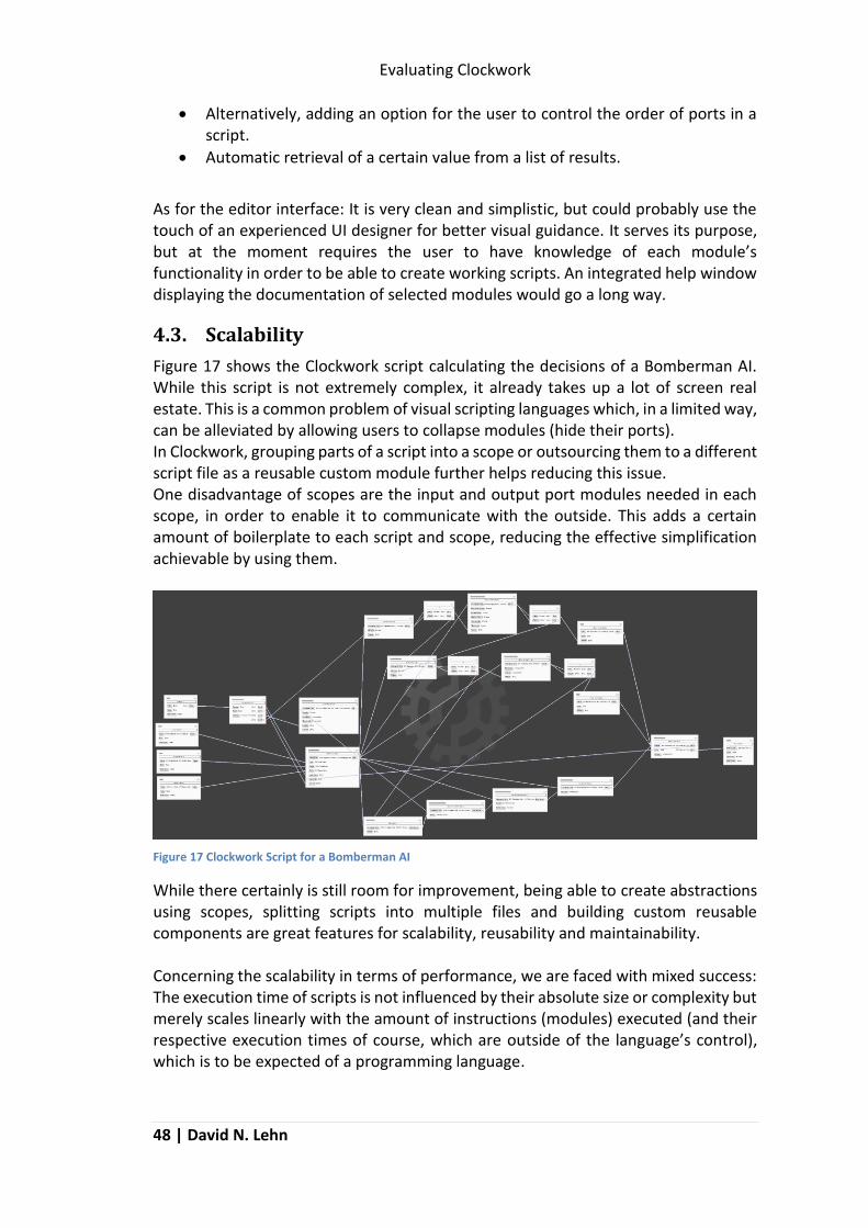
Evaluating Clockwork
48 | David N. Lehn
Alternatively, adding an option for the user to control the order of ports in a script.
Automatic retrieval of a certain value from a list of results.
As for the editor interface: It is very clean and simplistic, but could probably use the touch of an experienced UI designer for better visual guidance. It serves its purpose, but at the moment requires the user to have knowledge of each module’s functionality in order to be able to create working scripts. An integrated help window displaying the documentation of selected modules would go a long way.
4.3. Scalability
Figure 17 shows the Clockwork script calculating the decisions of a Bomberman AI. While this script is not extremely complex, it already takes up a lot of screen real estate. This is a common problem of visual scripting languages which, in a limited way, can be alleviated by allowing users to collapse modules (hide their ports). In Clockwork, grouping parts of a script into a scope or outsourcing them to a different script file as a reusable custom module further helps reducing this issue. One disadvantage of scopes are the input and output port modules needed in each scope, in order to enable it to communicate with the outside. This adds a certain amount of boilerplate to each script and scope, reducing the effective simplification achievable by using them.
Figure 17 Clockwork Script for a Bomberman AI
While there certainly is still room for improvement, being able to create abstractions using scopes, splitting scripts into multiple files and building custom reusable components are great features for scalability, reusability and maintainability. Concerning the scalability in terms of performance, we are faced with mixed success: The execution time of scripts is not influenced by their absolute size or complexity but merely scales linearly with the amount of instructions (modules) executed (and their respective execution times of course, which are outside of the language’s control), which is to be expected of a programming language.

Evaluating Clockwork
Designing a Visual Scripting System | 49
Memory consumption however is not as optimal. A script (including any other scripts it depends on, their dependencies, etc.) is stored in memory entirely at all times. This includes all data required by each module within these scripts, like port configurations and especially any default input values. In larger scripts, this can lead to a significant amount of memory to be reserved by a script, even if it is not actively being executed. This issue however is hard to resolve without greatly increasing the complexity of the language (dynamically loading parts of a script as required) as well as sacrificing execution performance (loading a script from disk is slow).
4.4. Safety
To judge the safety of Clockwork, we need to consider two things:
Does the language prevent the user from building invalid scripts?
How does the language recover from errors if the user does manage to build an invalid script?
As far as building invalid scripts is concerned, the Clockwork language offers several layers of safety: every connection formed by the user is checked at construction time to ensure that input and output types match. This is, however, compromised by the decision to include a wildcard type connectable to any other port. In addition to regular type checking, it is possible to integrate semantic type checking by implementing a special wrapper Value type for a certain data type in order to enforce correct semantics (see for example CW::StringValue and CW::TypeValue: While both act as wrappers for an std::string object, the latter can only store strings that are valid type identifiers and prevents the user from entering any invalid values). Finally, each module has the option to implement input value checks, allowing them to sanitize inputs both at construction and at runtime. If the user manages to build an invalid script (e.g. by forwarding an incompatible value type through a module using wildcard ports), the language uses runtime type checks to ensure that any value arriving at an input port is of the correct type. If the type is correct, the value is then handed on to a module’s sanitization function prior to activating it. If the type is not correct, an error is reported (allowing the Clocksmith debugger to pause execution) and the received input is ignored. This may result in a script not being executed correctly, but will prevent crashes. Executing a program within the Clocksmith debugger will also catch any C++ exceptions thrown by incorrectly implemented modules (Clockwork modules must not throw exceptions). This however still cannot prevent system level exceptions (e.g. access violations) or other implementation-related faults like infinite loops, which leaves a significant responsibility to module developers. Overall, we can say that we have for the most part achieved the goal of safety on the user’s level: any faults caused by user built scripts (including infinite loops, recursive inclusion of other scripts and incorrect inputs) can be caught by Clockwork and can be recovered from.

Evaluating Clockwork
50 | David N. Lehn
Unfortunately, module developers are still responsible for ensuring that no crashes are caused within their code. While Clockwork can guarantee any inputs received by a module to be of the correct type, it cannot guarantee that the module developer will use them correctly. It is therefore not possible to guarantee that a script will not crash during execution, since C++ does not allow all types of exceptions possibly caused by a custom module to be caught by Clockwork.
4.5. Debuggability
How difficult is it for a user to spot a flaw in his script? Clockwork and Clocksmith provide a wide range of features for detecting and reporting flaws:
Manual pausing
Manual breakpoints placeable on every input and output port
Automatic breaking when an error is encountered at runtime (the severity of an error required to cause an automatic break can be controlled using the debugging controls shown in Figure 18)
Highlighting of the current execution path (call stack) when paused
Examining and editing input and output values during execution
Additionally, Clocksmith generates error reports useful for module developers when a module throws a (catchable) exception. With this, Clockwork and Clocksmith provide a powerful set of tools for debugging, which sufficiently fulfils the requirement of debuggability. There are, however, several features still missing which could further improve the debugging experience:
Watchlist for values: Allowing the user to define a list of input ports the values of which can be monitored and neatly arranged in one place.
Conditional breakpoints: Breakpoints which are only triggered when certain conditions are met.
Allowing the entire script to be rearranged and connections to be modified while debugging, instead of only allowing values to be modified.
Live code flow visualization: Showing module execution in real time instead of only highlighting the call stack while execution is paused. Also, allowing for delayed execution, inserting delays between each module execution to make it easier to follow.
Figure 18 Clocksmith Debugging Controls

Evaluating Clockwork
Designing a Visual Scripting System | 51
4.6. Performance
While the aspect of performance has always been kept in mind while developing Clockwork, at some points speed had to be sacrificed for the sake of simplicity. This is not necessarily a bad thing, but the cost has to be considered nonetheless. The biggest decisions with a negative impact on performance are:
Introducing a wildcard type, requiring the language to perform runtime type checking.
Using strings instead of numeric indices to identify types.
Storing an entire script in memory at all times.
Storing connections on both input and output ports to simplify keeping them consistent (otherwise storing only outgoing connections would suffice).
Unfortunately, since we do not have alternative implementations of the language following other design decisions, it is hard to measure their actual impact in practical applications. There is one comparison we can draw, although it should be taken with a grain of salt: The AI script we have been using as an example so far is a nearly exact replica of an existing hardcoded AI called Cerb3rus AI. The modules implemented by the Bomberman AI library for Clockwork are for the most part exact mappings to the (low level) utility functions used by the Cerb3rus AI, with the Clockwork script recreating its high level logic. Functionally, both AIs are identical. In theory, this should make the resource consumption of the Clockwork script comparable to that of the hardcoded AI, with any discrepancy being attributable to the overhead caused by the scripting language. Reality, however, does not so easily conform to our expectations. Figure 19 shows the memory and processor time consumed by both AIs (recorded using Windows’ Performance Monitor utility). This data was recorded by having both AIs join the same match and fight each other. The graphs labelled cerb3rus_ai_Release show the performance of the hardcoded C++ AI while the ones of the scripted Clockwork AI are labelled case (Clockwork Autonomous Script Execution, an interpreter for executing Clockwork scripts outside of the Clocksmith editor, to avoid measuring the overhead caused by the GUI). As expected, the Clockwork script has a significantly higher memory consumption (almost 50% or 2MB) than the pure C++ binary code, which is mostly attributable to the overhead of the RTTS and the additional data required to store the structure of the script (connections, default values, etc.). Since this is a relatively small script however, the relative impact on memory consumption can be expected to be less for larger scripts.

Evaluating Clockwork
52 | David N. Lehn
Figure 19 Performance Comparison of Bomberman AIs in C++ and Clockwork
Of interest, however, is the compared processor time required by each AI to calculate their moves. Here, the Clockwork script is consistently and significantly faster than the hardcoded AI. This is unexpected, since both AIs show identical behaviour and should perform the same calculations. The most probable cause for this discrepancy is the structure of the Clockwork script: While the hardcoded AI evaluates all of its options before making a decision, the script evaluates the options in the order in which they would be considered for the decision, allowing it to skip the evaluation of options that would not be selected anyway. This, unfortunately, makes comparing the processor times required by both programs an exercise in futility.

Conclusion: This is the End
Designing a Visual Scripting System | 53
Conclusion: This is the End
… so, was it worth the effort? Over the course of this paper, we have successfully designed and implemented a new visual scripting language, complete with its own interpreter, editor and debugger. We have managed to design the language in a way that is flexible, can be dynamically extended by both programmers and non-programmers, can be ported and integrated into almost any kind of system, and can be expanded to be useful for almost any kind of purpose. We have demonstrated these features by building an artificial intelligence capable of playing Bomberman19, by building a set of custom extensions for our language and using them to build the AI script. Whether the language, in the end, is truly the universal solution we claim it to be, will only be shown by time and (hopefully) the many different cases in which it will be used. One thing however, which has already become evident during the designing stages, is that the language is naturally more suited to some applications than it is to others. It has been built with the development of application- and game-logic in mind, sacrificing traits that would be desirable for developing data processing algorithms (e.g. image processing). While Clockwork can easily be adapted to allow both, its lack of automatic parallelization and similar features will not allow it to compete with the performance of other languages specifically built for this purpose. The fact, however, that Clockwork does allow these different applications, and allows them to be implemented in an uncomplicated way using a minimum of code, is a sign that we have succeeded in our mission. While it may not always the most performant solution, it will always be an option: Why invent a new scripting system, if there is an existing one that can easily be adapted to the purpose at hand? Nevertheless, the language we have built is only a beginning, there are still many aspects with room for improvement:
Inheritance and type conversion: Allow types in the RTTS to specify base classes and other types to which they are compatible and/or convertible.
User-defined data types: Allow users to define custom data types, in addition to the existing possibility to create custom modules.
Multithreading support: As of now, the language only supports single-threaded execution. Adding parallelization features on the language level will allow performance improvements in many applications.
Advanced debugging features: While Clocksmith already offers several debugging features, further tools (discussed in chapter 4.5) could further simplify the debugging process.
19 Which, as of the time of this writing, proudly remains unbeaten.

Conclusion: This is the End
54 | David N. Lehn
Show module documentation in editor: So far, the documentation for each module has to be looked up separately, making this directly accessible within the editor would be a great improvement to usability.
Improved visuals: So far, the Clocksmith interface is rather utilitarian, as it was designed by a programmer. Adding further features like colour- or symbol-coded modules, fluent animations and improved navigation would improve the user experience and may make scripts easier to understand at a glance.
Expanded standard library: So far, Clockwork itself offers only a handful of integrated value types and modules. Adding more built-in, generic features to the language will increase the amount of options available to the user as well as decrease the amount of custom modules required to be built in order to adapt Clockwork to a certain purpose.
Performance optimization: Performance can still be improved in some places, however this should be done with care, in order to not compromise the simplicity and maintainability of Clockwork’s core code.
Finally we can conclude that, although there is still much room for improvement, we have successfully made Clockwork a simple, flexible and extensible visual scripting language, thereby fulfilling our initial goals.

Bibliography
Designing a Visual Scripting System | 55
Bibliography
Burnett, Margaret M., Atwood, John W. Jr and Welch, Zachary T. 1998. Implementing level 4 liveness in declarative visual programming languages. Visual Languages, 1988. Proceedings. 1998 IEEE Symposium on Visual Languages. 1998, pp. 126-133. cppreference.com. 2014a. dynamic_cast conversion - cppreference.com. cppreference.com. [Online] 3 Novemeber 2014a. [Cited: 13 January 2015.] http://en.cppreference.com/w/cpp/language/dynamic_cast. —. 2013a. std::type_info::name - cppreference.com. cppreference.com. [Online] 31 May 2013a. [Cited: 13 January 2015.] http://en.cppreference.com/w/cpp/types/type_info/name. Epic Games, Inc. 2014a. UDK | KismetUserGuide. UDN. [Online] Epic Games, Inc., 10 June 2014a. [Cited: 7 January 2015.] https://udn.epicgames.com/Three/KismetUserGuide.html. —. 2014c. UDK | KismetVisualDebugger. UDN. [Online] Epic Games, Inc., 10 June 2014c. [Cited: 19 January 2015.] https://udn.epicgames.com/Three/KismetVisualDebugger.html. —. 2015b. Unreal Engine | Blueprint Debugging. Unreal Engine Technology. [Online] Epic Games, Inc., 15 Janiary 2015b. [Cited: 19 January 2015.] https://docs.unrealengine.com/latest/INT/Engine/Blueprints/UserGuide/Debugging/index.html. —. 2015. Unreal Engine | Blueprint Overview. Unreal Engine Technology. [Online] Epic Games, Inc., 5 January 2015. [Cited: 7 January 2015a.] https://docs.unrealengine.com/latest/INT/Engine/Blueprints/Overview/index.html. —. 2014b. Unreal Engine | Blueprints Visual Scripting. Unreal Engine Technology. [Online] Epic Games, Inc., 18 December 2014b. [Cited: 7 January 2015.] https://docs.unrealengine.com/latest/INT/Engine/Blueprints/index.html. Fitzgerald, Scott and converter (User). 2013. Flow Graph Node Composition - CRYENGINE Manual - Documentation. CRYENGINE Manual - Documentation. [Online] Crytek GmbH, 18 November 2013. [Cited: 7 January 2015.] http://docs.cryengine.com/display/SDKDOC2/Flow+Graph+Node+Composition. Google. 2014a. Blockly -- Google Developers. Google Developers. [Online] Google, 3 December 2014a. [Cited: 7 January 2015.] https://developers.google.com/blockly/. —. 2014c. Code Generators - Blockly -- Google Developers. Google Developers. [Online] Google, 17 October 2014c. [Cited: 7 January 2015.] https://developers.google.com/blockly/installation/code-generators. —. 2014b. Defining Blocks - Blockly -- Google Developers. Google Developers. [Online] Google, 13 October 2014b. [Cited: 1 January 2015.] https://developers.google.com/blockly/custom-blocks/defining-blocks. —. 2014f. JavaScript Interpreter - Blockly -- Google Developers. Google Developers. [Online] Google, 17 October 2014f. [Cited: 19 January 2015.] https://developers.google.com/blockly/installation/js-interpreter. —. 2014e. Mutators - Blockly -- Google Developers. Google Developers. [Online] Google, 17 October 2014e. [Cited: 16 January 2015.] https://developers.google.com/blockly/custom-blocks/mutators.

Bibliography
56 | David N. Lehn
—. 2014d. Type Checks - Blockly -- Google Developers. Google Developers. [Online] Google, 17 October 2014d. [Cited: 8 January 2015.] https://developers.google.com/blockly/custom-blocks/type-checks. Hils, Daniel D. 1992. Visual Languages and Computing Survey: Data Flow Visual Programming Languages. Journal of Visual Languages and Computing. 1992, Vol. 3, 1, pp. 69-101. Hoba, Sascha and Johnson, Adam. 2013a. Flow Graph Debugger - CRYENGINE Manual - Documentation. CRYENGINE Manual - Documentation. [Online] Crytek GmbH, 15 July 2013a. [Cited: 19 January 2015.] http://docs.cryengine.com/display/SDKDOC2/Flow+Graph+Debugger. Hoba, Sascha. 2013b. Flow Graph Module System - CRYENGINE Manual - Documentation. CRYENGINE Manual - Documentation. [Online] Crytek GmbH, 20 November 2013b. [Cited: 7 February 2015.] http://docs.cryengine.com/display/SDKDOC2/Flow+Graph+Module+System#FlowGraphModuleSystem-C++Interface. Johnson, Adam and prasitasankar (User). 2013. Flow Graph Editor - CRYENGINE Manual - Documentation. CRYENGINE Manual - Documentation. [Online] Crytek GmbH, 13 July 2013. [Cited: 7 January 2015.] http://docs.cryengine.com/display/SDKDOC2/Flow+Graph+Editor. Johnston, Wesley M., Hanna, J. R. Paul and Millar, Richard J. 2004. Advances in Dataflow Programming Languages. ACM Computing Surveys. 2004, Vol. 36, 1, pp. 1-34. Kappel, Gerti, et al. 1989. An Object-Based Visual Scripting Environment. [book auth.] D. Tsichritizis. Object Oriented Development. s.l. : Ed. Centre Universitaire d'Informatique, Universite de Geneve, 1989. Kim, Mansoo, Visual Inf. Lab., Electron. & Telecommun. Res. Inst., Taejeon, South Korea and Lee, EaTaek. 1998. A visual interface for scripting virtual behaviors. Computer Human Interaction, 1998. Proceedings. 3rd Asia Pcific. Shonan Village Center : IEEE, 1998. Myers, Brad A. 1990. Taxonomies of Visual Programming and Program Visualization. Journal of Visual Languages & Computing. 1990, Vol. 1, 1, pp. 97-123. Porter, Brett G. 2012. Friday Linked List (06/01/12). Art & Logic. [Online] 1 June 2012. [Cited: 28 January 2015.] http://www.artandlogic.com/blog/2012/06/friday-linked-list-060112/. Python Software Foundation. Welcome to Python.org. Python.org. [Online] Python Software Foundation. [Cited: 6 January 2015.] https://www.python.org/. Simmons, Jason. 1992. Dyna Blaster / Bomber Man Review. Amiga Action. May 1992, Vol. 32, pp. 62-63. Unity Technologies. 2014. Unity - Manual: Controls (Legacy). Unity - Manual. [Online] Unity Technologies, 20 November 2014. [Cited: 21 January 2015.] http://docs.unity3d.com/Manual/gui-Controls.html. World of Level Design. 2012. UDK Kismet Introduction. World of Level Design. [Online] 13 March 2012. [Cited: 28 January 2015.] http://www.worldofleveldesign.com/categories/wold-members-tutorials/petebottomley/udk-kismet-introduction.php.

Table of Figures
Designing a Visual Scripting System | 57
Table of Figures
Figure 1 Printing the fibonacci sequence up to n in C++ and Python (Python Software Foundation). .................................................................................................................. 1
Figure 2 Example of an Unreal Kismet Script (World of Level Design, 2012) ............... 3
Figure 3 Example of a Flow Graph Script (Johnson, et al., 2013) .................................. 4
Figure 4 Example of a Blockly Script (Porter, 2012) ...................................................... 5
Figure 5 Common Elements of Visual Scripting Languages .......................................... 8
Figure 6 Structure of the Clockwork Runtime Type System ....................................... 22
Figure 7 Required Interface for Types in the Clockwork Runtime Type System ......... 23
Figure 8 Minimum Boilerplate Code Required for a Type Using the Clockwork RTTS 23
Figure 9 The core interface of Clockwork's Value class .............................................. 24
Figure 10 Interface of the Clockwork Module class, relevant to Module developers 27
Figure 11 Example: Execution of a Clockwork Scope .................................................. 30
Figure 12 Example of a Module Editor in Clocksmith ................................................. 41
Figure 13 Traditional GUI Creation vs Clocksmith GUI ................................................ 42
Figure 14 Interaction Between Clocksmith and Clockwork When Debugging ........... 44
Figure 15 Example implementation of a custom Value type in Clockwork ................ 46
Figure 16 Visual Value Editor Generated by Figure 15 ............................................... 46
Figure 17 Clockwork Script for a Bomberman AI ........................................................ 48
Figure 18 Clocksmith Debugging Controls .................................................................. 50
Figure 19 Performance Comparison of Bomberman AIs in C++ and Clockwork ......... 52

Appendix
58 | David N. Lehn
Appendix
A.1 CanPlaceBombModule – Header File // *.h file class CWAI_DECL CanPlaceBombModule: public CW::Module { public: // Enums for addressing input and output ports. // Not required, but useful. enum Input { In_GameplayData, In_LitFuse, In_Trigger, In_Count }; enum Output { Out_Result, Out_Count }; // Required to expose this type to the Clockwork RTTS. CW_DECLARE_MODULE_TYPE_INTERFACE(CanPlaceBombModule); using CW::Module::Module; CanPlaceBombModule(); protected: // This function performs the module's internal logic. void onActivate(C3::uint _port, bool _inputChanged) override; };

Appendix
Designing a Visual Scripting System | 59
A.2 CanPlaceBombModule – Source File
// *.cpp // Code required to expose this module to the Clockwork RTTS: CW_DEFINE_MODULE_TYPE_INTERFACE(CanPlaceBombModule, // Module Type to expose C3_SINGLE_ARG({ // Additional information about the type "Can Place Bomb", // Alias of the type displayed in editor "Bomberman/Assessment" // Category to which to add this type })); CanPlaceBombModule::CanPlaceBombModule() { numInputs(In_Count); // Set the number of inputs // Set information of an input port: Index, Description, Type (optional), // Default Value (optional) inputPort(In_GameplayData, "Gameplay Data", GameplayDataValue::typeIdent()); inputPort(In_LitFuse, "Lit Fuse", CW::BoolValue::typeIdent(), CW::BoolValue(true)); inputPort(In_Trigger, "Trigger"); numOutputs(Out_Count); // Set the number of outputs // Set information of an output port: Index, Description, Type outputPort(Out_Result, "Result", CW::BoolValue::typeIdent()); } void CanPlaceBombModule::onActivate(C3::uint _port, bool _inputChanged) { switch (_port) { case In_Trigger: { // When the input port In_Trigger is activated: // Get input values from ports: GameplayData* data = input(In_GameplayData).as<GameplayData*>(); bool isTrap = !input(In_LitFuse).as<bool>(); // Report a runtime error if an incorrect value has been passed. // This will allow the user to pause execution when debugging. if (!data) { C3_LOG(Error) << "Can't calculate bomb placement safety without "
"access to gameplay data. No calculations performed, " "output will not be triggered.";
return; } // [do some calculations] // Return the result on port Out_Result. activateOutput(Out_Result, result); break; } } }

Appendix
60 | David N. Lehn
A.3 AIRuntime – Header and Source File // *.h file class CWAI_DECL AIRuntime: public CW::Runtime { public: // Required to expose the type to the Clockwork RTTS. CW_DECLARE_RUNTIME_TYPE_INTERFACE(AIRuntime); AIRuntime(CW::Scope* _scope); // CW::Runtime interface void execute() override; private: C3::uint m_InLocal; // [more port indices] };
// *.cpp file // Required to expose type to the Clockwork RTTS CW_DEFINE_RUNTIME_TYPE_INTERFACE(AIRuntime, // Type to be exposed C3_SINGLE_ARG({"Clockwork AI", // Alias of the type to be displayed in editor { // Required input ports (Name, Type) {"Local State", "CWAI::LocalStateValue"}, // [more] }, { // Required output ports (Name, Type) {"Action", "CWAI::PlayerControlTypeValue"}, // [more] }}));
AIRuntime::AIRuntime(CW::Scope* _scope) : CW::Runtime(_scope) { // Fetch and store port indices by name m_InLocal = inputIndex("Local State"); // [more] }
void AIRuntime::execute() { // [some code] PlayerControlType move = PLAYER_CONTROL_NONE; // Set required input values. m_Scope->execute(m_InLocal, LocalStateValue(&_local)); m_Scope->execute(m_InGlobal, GlobalStateValue(&_global)); m_Scope->execute(m_InGame, GameStateValue(&_game)); // Execute the main AI calculations auto result = m_Scope->execute(m_InGetAction, CW::DynamicValue()); for (auto& r : result) { // Find the required output in the list of returned values if (r.port == m_OutAction) { move = r.value->as<PlayerControlType>(); break; } } // [send move, more code] }