designing an inertia actuator with a fast rotating gyro
TRANSCRIPT

1
Designing an Inertia Actuator with a Fast RotatingGyro inside an Egg-shaped Robot
Chun-Chi Wang, He-Zhi Liu, Rui-Yuan Lin, Li-Yang Lu and N. Michael Mayer
Abstract— In this paper, we describe features of two newrobot prototypes that are actuated by an actively controlledgyro (flywheel, symmetric rotor) inside a hollow sphere thatis located in the middle of the robots. No external actuatorsare used. The outside structure of the robots and the gyro areconnected by a gimbal, which is similar in structure to a controlmoment gyroscope in spacecrafts. The joints of the gimbal canbe actuated. In this way, the orientation of axis for the gyroin relation to the egg can be changed. Since the inertia of thefast rotating gyro is large in relation to the outside structure, arelative rotation of the axis against the outside structure resultsin a motion of the egg by inertia principle. In this way, we canuse this principle for controlling the robot to move forward andturn around. The robots are shaped as spheroidal ellipsoids sothey resemble eggs. So far, we have built and tested two robotprototypes.
Index Terms—Mobile robots, actuators, gyro actuator.
I. INTRODUCTION AND RELATED RESEARCH
EARLIER projects of gyro actuated robots are the Gy-rover at the Carnegie Mellon University [1] and Gyrobot
projects [2]. They use a fast spinning gyro mounted in a wheel-shaped robot, balancing the robot by tilting the flywheel. Andforward motion is produced by another motor.
Joydeep Biswas [3] implements the wheel robot Reactobotby actuating an internal reaction wheel. The axis of thereaction wheel is the same as the forward direction, turningthe reaction wheel can affect the robot turning in motion.
Gyros have been used for the stabilization of biped robots[4][5]. Further ideas were to stabilize also the pitch of therobot by using the gyro at the same time as a reaction wheel[6].
The idea came up to allow the robot to make rapid move-ments by adding a brake mechanism (same as a car brake)to produce a large torque in order to allow rapid movementssuch as somersault and quickly standing up.
Jumping Joe robots were presented at the NEDO hall at theAICHI world exhibition (EXPO 2005), near Nagoya, Japan.The momentum is produced by stopping the rotor with a carbrake. In that way, a very strong momentum has been achieved
Research supported by Advanced Institute of Manufacturing with High-techInnovations (AIM-HI)
Chun-Chi Wang and He-Zhi Liu was with Department of Electrical En-gineering, National Chung Cheng University, Chiayi, 621, Taiwan. (e-mail:[email protected], [email protected]).
Rui-Yuan Lin and Li-Yang Lu is with Department of Electrical Engi-neering, National Chung Cheng University, Chiayi, 621, Taiwan. (e-mail:[email protected], [email protected]).
N.Michael Mayer is with the Department of Electrical Engineering, Na-tional Chung Cheng University, Chiayi, 621, Taiwan (corresponding author,e-mail: [email protected]).
and the robot could stand up rapidly. Similar principles havebeen used in the Cubli robot [7].
In spacecraft or satellite, a momentum wheel (or gyroscope)is used for gyroscopic stabilization and orientation. The prin-ciple is conservation of angular momentum- accelerating areaction wheel brings about a proportional response by therest of a spacecraft or satellite. In addition, designs similar tothose outlined here for our robot are known there as ControlledMomentum Gyroscopes [8].
Recently, more approaches have been brought up inrobotics. One example is bicycle robots manufactured byMurata (as Murata boy on their webpage) [9] and other compa-nies. In addition, Northwestern University recently presenteda Conservation of Angular Momentum Locomotion Robot(Fluffbot) on their webpage [10].
Various toys are based on gyro effects. One example is theDynabee device that can be used to train the hand musclesthat use outside applied torque for further acceleration. Thephysics of the Dynabee is outlined in [11].
Comprehensive, encapsulated robots usually are formed intospheres (Sphero1, Star Wars2 BB-8 toys, etc.), and they areactuated by a heavy weight that shifts along the inside of thethin wall of the robot’s hull. This design allows for a limitedtorque and has other disadvantages versus the design that ispresented here. Although those products from outside appear
1https://www.sphero.com/2Trademark of Lucasfilm Ltd., San Francisco, California
Fig. 1. Our two robot prototypes. 1st prototype (left, 63x40cm), 2ndprototype (right, bumblebee, 44x32cm).
arX
iv:1
905.
1013
4v1
[cs
.RO
] 2
4 M
ay 2
019
2
��������������������������������������������������������������������������������������������������������������
��������������������������������������������������������������������������������������������������������������
������������������������������������������������������������������������������������������������������������������������������������������������������������������������������������
������������������������������������������������������������������������������������������������������������������������������������������������������������������������������������
������������������������������������������������������������������������������������������������������������������������������������������������������������������������������������
������������������������������������������������������������������������������������������������������������������������������������������������������������������������������������
����������������������������������������������������������������������������������������������������������������������������������������������������������������������������������������������������������������������������������������������������������������������������������������������������
����������������������������������������������������������������������������������������������������������������������������������������������������������������������������������������������������������������������������������������������������������������������������������������������������
Spherical encapsulation (ball)
Differential drive robot r
R
α
����������������������������������������
����������������������������������������
�����������������������������������
�����������������������������������
�����������������������������������
�����������������������������������
����������������������������������������������������������������������������������������������������������������������������������������������������������������������������������������������������������������������������������������������������������������������������������������������������
����������������������������������������������������������������������������������������������������������������������������������������������������������������������������������������������������������������������������������������������������������������������������������������������������
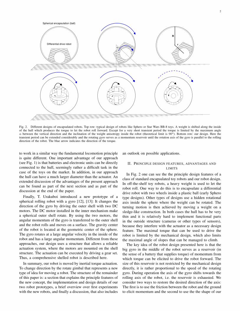
Fig. 2. Different designs of encapsulated robots. Top row: typical design of robots like Sphero or Star Wars BB-8 toys. A weight is shifted along the insideof the hull which produces the torque to let the robot roll forward. Except for a very short transient period the torque is limited by the maximum angleα between the vertical direction and the inclination of the weight anisotropy inside the robot (theoretical limit is 90o). Bottom row: our design. Here thetransient period can be extended considerably and the rotating gyro serves as a momentum reservoir until the rotation axis of the gyro is parallel to the rollingdirection of the robot. The blue arrow indicates the direction of the torque.
to work in a similar way the fundamental locomotion principleis quite different. One important advantage of our approach(see Fig. 1) is that batteries and electronic units can be directlyconnected to the hull, seemingly rather a difficult task in thecase of the toys on the market. In addition, in our approachthe hull can have a much larger diameter than the actuator. Anextended discussion of the advantages of the present approachcan be found as part of the next section and as part of thediscussion at the end of the paper.
Finally, T. Urakuboi introduced a new prototype of aspherical rolling robot with a gyro [12], [13]: It changes thedirection of the gyro by driving the outer shell with two DCmotors. The DC motor installed in the inner mechanism makea spherical outer shell rotate. By using the two motors, theangular momentum of the gyro is transferred to the outer shelland the robot rolls and moves on a surface. The gravity centerof the robot is located at the geometric center of the sphere.The gyro rotates at a large angular velocity in the inside of therobot and has a large angular momentum. Different from theseapproaches, our design uses a structure that allows a reliableactuation system, where the motors are mounted on the shellstructure. The actuation can be executed by driving a gear set.Thus, a comprehensive shelled robot is described here.
In summary, our robot is moved by inertial torque actuation.To change direction by the rotate gimbal that represents a newtype of idea for moving a robot. The structure of the remainderof this paper is: a section that explains the principle features ofthe new concept, the implementation and design details of ourtwo robot prototypes, a brief overview over first experimentswith the new robots, and finally a discussion, that also includes
an outlook on possible applications.
II. PRINCIPLE DESIGN FEATURES, ADVANTAGES ANDLIMITS
In Fig. 2 one can see the the principle design features of aclass of standard encapsulated toy robots and our robot design.In off-the-shelf toy robots, a heavy weight is used to let therobot roll. One way to do this is to encapsulate a differentialdrive robot with two wheels inside a plastic ball (early Spherotype designs). Other types of designs use a hidden rotationalaxis inside the sphere where the weight can be rotated. Theturning motion is then achieved by moving a weight on asledge-like construction. In both cases the hull has to be verythin and it is relatively hard to implement functional partsin the outside structure (cameras or other types of sensors),because they interfere with the actuator as a necessary designfeature. The maximal torque that can be used to drive therobot is limited by the mechanical design, which also limitsthe maximal angle of slopes that can be managed to climb.
The key idea of the robot design presented here is that thebig gyro in the middle of the robot serves as a reservoir (inthe sense of a battery that supplies torque) of momentum fromwhich torque can be elicited to drive the robot forward. Thesize of this reservoir is not restricted by the mechanical designdirectly, it is rather proportional to the speed of the rotatinggyro. During operation the axis of the gyro shifts towards therolling axis of the robot, i.e. the reservoir is exhausted. Weconsider two ways to restore the desired direction of the axis:The first is to use the friction between the robot and the groundto elicit momentum and the second to use the the shape of our
3
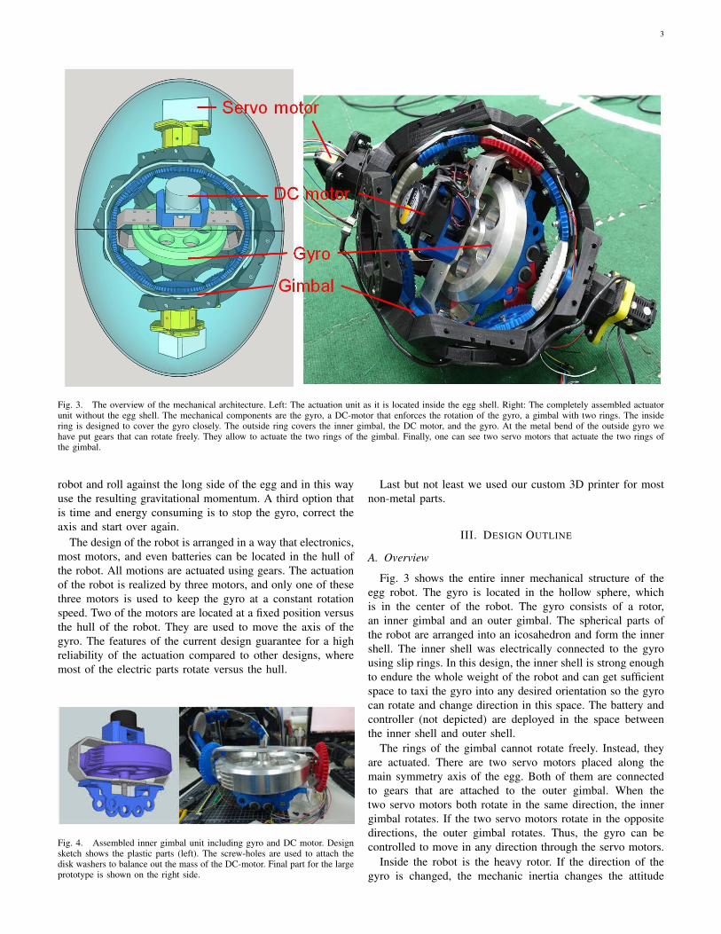
Fig. 3. The overview of the mechanical architecture. Left: The actuation unit as it is located inside the egg shell. Right: The completely assembled actuatorunit without the egg shell. The mechanical components are the gyro, a DC-motor that enforces the rotation of the gyro, a gimbal with two rings. The insidering is designed to cover the gyro closely. The outside ring covers the inner gimbal, the DC motor, and the gyro. At the metal bend of the outside gyro wehave put gears that can rotate freely. They allow to actuate the two rings of the gimbal. Finally, one can see two servo motors that actuate the two rings ofthe gimbal.
robot and roll against the long side of the egg and in this wayuse the resulting gravitational momentum. A third option thatis time and energy consuming is to stop the gyro, correct theaxis and start over again.
The design of the robot is arranged in a way that electronics,most motors, and even batteries can be located in the hull ofthe robot. All motions are actuated using gears. The actuationof the robot is realized by three motors, and only one of thesethree motors is used to keep the gyro at a constant rotationspeed. Two of the motors are located at a fixed position versusthe hull of the robot. They are used to move the axis of thegyro. The features of the current design guarantee for a highreliability of the actuation compared to other designs, wheremost of the electric parts rotate versus the hull.
Fig. 4. Assembled inner gimbal unit including gyro and DC motor. Designsketch shows the plastic parts (left). The screw-holes are used to attach thedisk washers to balance out the mass of the DC-motor. Final part for the largeprototype is shown on the right side.
Last but not least we used our custom 3D printer for mostnon-metal parts.
III. DESIGN OUTLINE
A. Overview
Fig. 3 shows the entire inner mechanical structure of theegg robot. The gyro is located in the hollow sphere, whichis in the center of the robot. The gyro consists of a rotor,an inner gimbal and an outer gimbal. The spherical parts ofthe robot are arranged into an icosahedron and form the innershell. The inner shell was electrically connected to the gyrousing slip rings. In this design, the inner shell is strong enoughto endure the whole weight of the robot and can get sufficientspace to taxi the gyro into any desired orientation so the gyrocan rotate and change direction in this space. The battery andcontroller (not depicted) are deployed in the space betweenthe inner shell and outer shell.
The rings of the gimbal cannot rotate freely. Instead, theyare actuated. There are two servo motors placed along themain symmetry axis of the egg. Both of them are connectedto gears that are attached to the outer gimbal. When thetwo servo motors both rotate in the same direction, the innergimbal rotates. If the two servo motors rotate in the oppositedirections, the outer gimbal rotates. Thus, the gyro can becontrolled to move in any direction through the servo motors.
Inside the robot is the heavy rotor. If the direction of thegyro is changed, the mechanic inertia changes the attitude

4
(a) Principle design (b) S1 drives the gears clockwise and S2anti-clockwise.
(c) Both S1 and S2 rotate clockwise.
Fig. 5. Mechanics and gear set to control the actuation of the gimbals. (a) Principle design of 1st (right) and 2nd prototype (left). Gears can be used in twodifferent modes or by a linear superposition of them. In the first mode (b) the servo motors rotate in opposite direction (clockwise and anti-clockwise or viceversa) thus, the gears are blocked and that results in a rotation of the outer gimbal. In the second mode (c) the rotation of the gears transports the motion tothe inner gimbal no force is elicited on the outer gimbal and it rests at the same position. Also, any linear superposition of both types can be applied.
of the robot and results in a force that affects the robot’smovement. In this way, the robot can roll, rotate and spin.
B. Gimbal design
The keystone of our design is the utilizatin of the actuatedgimbal set. As mentioned before one feature of the design isto locate the controlling motors to the outside structure (”thehull”) of the robot. Since the DC motor is inside the gimbalit is still necessary to have electrical connections through therotation axes of the gimbal. This has been realized by usingtwo slip rings that provide a multitude of electrical connectionsthrough these joints. Alongside these function specificationswe have designed the gimbal structure.
The inner gimbal (cf. Fig. 4) is the basic frame for the rotorand the DC motor. It is a rigid metal part (6061 aluminiumalloy) and thus provides a stable frame for a controlled motionsystem for the gyro; it also lets the DC motor work stably inhigh speed. Power lines and the signal lines are connected intothe inner gimbal by means of 12 way slip rings. Slip rings areinstalled on one side of the inner gimbal. For balancing theweight of the DC motor, there are compensating disk washersat the opposite direction on the inner gimbal. Removing thosedisk washers would add an additional feature to the dynamics.The outer gimbal is a pivoted support that allows the pitchrotation of the rotor and installs a gear set on it. It is madefrom 6061 aluminum alloy.
Fig. 5 (a) shows the architecture of the outside ring of thegimbal set for both egg robots. The axis of both servo motorsconnects to the gears on the outer gimbal. Thus the servomotors can control the behavior of the gimbal by the gearset. When S1 rotates clockwise and S2 rotates anti-clockwise,or S1 rotates anti-clockwise and S2 rotates clockwise, thegears are blocked and the outer gimbal rotates (see Fig. 5
(b)). When S1 and S2 both rotate in a clockwise or anti-clockwise direction, the gears rotate. Thus, the inner gimbalrotates (see Fig. 5 (c)). In this way, the direction of the gyrocan be changed. The coexistence of bearings, slip rings, gimbalrings and others requires a sophisticated mechanical design,which is illustrated in the explosion sketch of Fig. 11.
The transmission can be described by following equations.[αβ
]=
1
2
[1 11 −1
] [γS1γS2
], (1)
where α is the angle of the outer gimbal, β is the inner angle,and γS1 and γS2 are the angles of each of the servo motors. Adetailed analysis of the kinematics and dynamics of the robotcan be found in [14].
Ten gears are working in a series to transmit the torque inthe mechanical system. All gears can rotate freely with respectto the outer gimbal ring (their frame). Two gears’ axes arefixed to either servo motor, S1 and S2. Two more gears axesare connected to the inner gimbal and control its rotation angle.
There are two types of gears with different sizes, the ratiobetween a big gear and a small gear was intended to be roughlyabout 2:1. The gears are not flat. Instead they are nestledclosely to the shape of the outer gimbal. They have to bedesigned as bevel gears that are actuated in a circle. Thus,they are shaped as a cutout piece of a sphere. The four smallgears placed at each side of the connection to inner gimbal arenecessary to drive the inner gimbal on par and synchronouslyfrom both sides.
In Fig. 6 one can see the design of the outer gimbal ring andthe composition of the gears. Spherical gears can be evaluatedby using the theory of bevel gear sets where all axes aredirected to the center of the gimbal ring, the curvature ofthe gears can be constructed as intersections to an imaginedspherical shell. The diameter of the big gears is one side of

5
Fig. 6. Outer gimbal ring design (left) and the gear set that is attached to the inside of the outer gimbal. One can see that the outer gimbal is not a ring. Itrather forms an irregular polygon with design imprints to make space for each of the gears at their corresponding location.
an octagon. Similarly, the diameter of the small gear is oneside of a hexadecagon. Both of two polygons are a tangentialpolygons that contain the circle which is a diameter of thethought circle of the gear set r. The diameter of each of thegears can then be calculated by the following equations.
Dbig−gear = 2r tan(π
8) (2)
and
Dsmall−gear = 2r tan(π
16). (3)
From the equations above, we calculated the ratio of bothgears:
Dsmall−gear
Dbig−gear=
tan( π16 )
tan(π8 )=
0.198912
0.414213= 0.480217 (4)
Since the teeth sizes of all gears should be roughly equaland the ratio of gear teeth numbers should be coprime integerswe chose the number ratio to be 48:23 (0.479167).
C. Gyro and DC brushless motor
The DC brushless motor is used to drive the gyro. It is fixedon the inner gimbal. The type of the motor is BLH230K-A.The maximum speed is 3000 rpm. It includes break function-ality, speed control, direction control, acceleration time settingand speed feedback. The BLH230K-A supports good stabilitywith regard to its speed when there are load variations. Themotor can compensate the moment and adjust to the goalspeed immediately. In the current configuration, the gyro isused with the constant speed of 3000 rpm. Currently, breakingfunctionality is not being used. In the future it might addadditional functionality to the gyro in the sense of a reactionwheel [15], [6], [5].
D. Gyroscope and accelerometer
The MPU-9255 is the Invensenses first generation 9-axis ac-tivity detection part, working in conjunction with the AARTM
activity detection library. The digital output of this devicecan be I2C or SPI. By reading the gyroscope sensor andaccelerometer, the attitude of the robot can be detected whilethe rolling motion is occurring. We implemented two of thesesensors on each robot. The first sensor is located at the hull,and the second sensor is located at the inner ring of the gimbal.
E. Controller
Due to the limited space in the egg robot, the main controllershould be small and compact. We chose a credit card sizecomputer named Raspberry Pi 2 to be the main controller. Ituses an ARM Cortex-A7 CPU with 1 GB RAM. The clockrate is 900 MHz in medium mode but can be tuned to 1GHz in overclocked mode. Thus, the computer can handlethe computation for controlling the robot. The RaspberryPi 2 contains extensive applications of standard interfaces,such as: USB host, HDMI output, Ethernet, UART, I2C andGPIO (General-purpose input/output). We installed Raspbian,which is a free operating system based on Debian optimizedfor the Raspberry Pi, on the computer. Thus, the computercan be used as a low-cost controlling system with motordrivers and sensors on operating system-level or hardware-level development.
F. Servo motors
The servo motors are used to drive the gimbal. The Dy-namixel MX-106 and EX-106 are actuators, each one hasa speed reducer, magnetic encoder, controller, driver andnetwork functionality. The servo motors use UART RS485 asa communication protocol for transferring data packages. Themaximum baud rate is 1M bit per second. The data packagescontain commands for the goal speed, goal position, goal

6
Fig. 7. The inner shell (left) and outer shell (middle) are both based on truncated icosahedrons where in the case of the outer shell the icosahedron iselongated in one direction. Due to the bending of each tile, the pressure forces from outside are redirected to the neighboring tiles which guarantees by meansof mutual tension an inert and sufficient stability of the robot.
torque and other controllable parameters. Also, we can getfeedback by analyzing the packages from the servo motors.Thus, the controller has the ability to track the motor‘s speed,position, temperature, voltage, current, and load.
G. Structure and shell
The inner shell is constructed by a set of 20 plastic tilesas shown in Fig. 7. These tiles are organized in the shapeof an icosahedron. The tiles had the shape of a regulartriangle. In order to find a way around size restrictions ofour rapid prototyping environment we truncated the edgesof each triangle to be rounder. As a consequence, after alltiles were assembled, the sphere reached a sufficient size. Inthis way we also could create a space between the gimbaland outer shell. In order to make a stronger structure andsmoother surface, we designed curved plates with six or five
Fig. 8. Small robot prototype with open shell and view towards the gyroactuator.
endpoints on the center of the pieces. Fig. 7 at the left showsthe pressure on the surface of the frame for each piece istransmitted to neighboring pieces. In this way, the outer shellis strong enough to support the whole weight of the robot.
Fig. 8 shows the smaller egg robot during the assemblingprocess. Due to its smaller size it was possible to merge tilesof the icosahedron for the prototyping process. So, it uses 14pieces to build an ellipsoid outer shell. Each piece of the outershell also stretches from the surface of the tiles of the innershell. The design concept for this type is to make an ellipsoidaland sealed shell in order to build a water-proof and dust-proofstructure that can roll smoothly. Each piece is a solid plate.
H. Power and system design
A set of Sanyo 18650ZY 2600mAh 3.7V Li-on batteries isused as a power supply. Since the DC brushless motor requiresa 24 V supply, seven of those batteries have been connectedin series with an additional protection circuit. Fig. 9 shows thepower sytstem in both prototypes. The circuit uses LM7812IC for switching the input voltage to 12 V and LM2576S-5 forswitching the input voltage to 5V. The two servomotors requirea 12 V supply and at least 1.5 A for full power driving. Thismeans we need two LM7812 ICs to supply 1 A of current.The control system and sensors need a total of about 5 V at0.5 A. The voltage switching circuit can afford the load fromthe components. The runtime of our robots with a completelycharged the battery set is about 1 hour if only the DC motor isenabled, and about 20 30 minutes if the robot is fully actuatedduring the entire time.
In our system design, we need a little embedded board tocontrol all the motors and sensors. Fig. 9 (right) shows theframe of the control system. The Raspberry Pi 2 is used forthe core board. It is used for processing data from sensorsand controlling the motors and connecting to the outsideworld via WLAN. The two servo motors are connected to

7
Fig. 9. Power system (left) and control and communication system (right).
the GPIO and communicate with the board via the UARTRS485 protocol. The nine-axes sensor which include gyro,accelerometer, magnetic and compass sensor is also connectedby the GPIO. It uses I2C to transmit the data. The DCbrushless motor is controlled by its control board. With thisboard, we can control the speed, direction and motions of theDC motor. The board is connected to the GPIO pins. There isa USB adapter for the wireless networking board.
IV. EXPERIMENTS
Both robots have been extensively tested and also have beenused in demonstrations. The two prototypes work very reliably.The new prototype has also been used on water. Demonstra-tions can also be found in the multi-media attachment andin the internet[16]. In addition, the core has been used inexperiments that used alternative shells. In one setting we putthe core into a large balloon ball (cf. fig. 10). The core couldmove the ball. Still, the ball was weakly actuated. However,we assume that if we increase the rotation speed from 3000rpm to a significantly higher number the core is capable tocontrol the ball. This setting can be seen as a prototype of arobot that is very large, but due to its light weight and softcushion it is safe in the direct environment of pedestrians. Itmight also be combined with other types of locomotion that
Fig. 10. Gyro actuator core inside a toy ball (ca. 1.7 m diameter), completesetting (left) and gyro core inside the ball (right).
are currently tested in our laboratory, such as a robot that usesinflatable cushions [17].
V. DISCUSSION AND OUTLOOK
In this paper, we present a robot with no mechanism thatdirectly interacts with the environment; it has a gyro in itscenter. Experiments with these robots show that using theangular momentum of the high speed rotating heavy rotor canwork against the moment of inertia of the egg robot and makeit move in a controlled fashion. Due to the enclosed shell,our robot prototypes and in a general sense our new type ofactuator may be used in technical applications in various fieldsamong rough environments such as underwater for work onunderwater cables, sand, underground passage and even spaceand extraterrestrial environments, for example Venus with itshigh pressure and acidic atmosphere. The actuator core canwork in all those environments by using the correspondingouter shell. In particular, we consider the following settings.
• Medical applications: A tiny version of the actuator corecan be implemented into a robot pill that can be combinedwith sensors for use in several types of medical exami-nations, where the attitude of the pill can be conrolled.
• Service and surveillance robots: The first studies into thisdirection have been outlined in Sect. IV. The robots canbe large and still very light in weight and soft. These typesof robots can be used in direct interaction with humansand used for advertising, eye catching, surveillance inparks and other things.
• Mobile access point for wireless services.Some of these ideas have been submitted as patent applica-tions.
The next step is to make the egg robot more controllable.The control system can be improved by finding suitablealgorithms or adding different sensors for a specific envi-ronment. Also, the egg robot could possibly be applied topractical applications in our daily life. The first step into thisdirection has been to derive an exact mathematical model ofits dynamics, of which results have been published in [14]. Ademo video of the larger prototype can be found at [16].

8
Fig. 11. The design concept of the inner structure for the robots, front view (left) and side view (right).
ACKNOWLEDGMENT
This work was supported by the Advanced Institute ofManufacturing with High-tech Innovations (AIM-HI), Min-istry of Science and Technology under the MOST 103-2221-E-194-039, and 102-2221-E-194-050-program, and our industrialcollaboration partner 1A Robotics.
REFERENCES
[1] S.-J. Tsai, E. D. Ferreira, and C. J. Paredis, “Control of the gyrover.a single-wheel gyroscopically stabilized robot,” in Intelligent Robotsand Systems, 1999. IROS’99. Proceedings. 1999 IEEE/RSJ InternationalConference on, vol. 1. IEEE, 1999, pp. 179–184.
[2] A. A. Mamun, Z. Zhen, P. Vadakkepat, and T. H. Lee, “Tracking controlof the gyrobot-a gyroscopically stabilized single-wheeled robot,” in 31stAnnual Conference of IEEE Industrial Electronics Society, 2005. IECON2005., Nov 2005, p. 6.
[3] J. Biswas and B. Seth, “Dynamic stabilization of a reaction wheel robot,”in 2008 International Journal of Factory Automation, Robotics and SoftComputing, Oct 2008, pp. 135–140.
[4] N. M. Mayer, K. Masui, M. Browne, M. Asada, and M. Ogino, “Using agyro as a tool for continuously variable lateral stabilisation of dynamicbipeds,” Applied Bionics and Biomechanics, vol. 3, no. 3, pp. 237–243,2006. [Online]. Available: https://doi.org/10.1533/abbi.2006.0032
[5] N. M. Mayer, K. Masui, M. Browne, and M. Asada, “Gyro stabilizedbiped walking,” in 2006 IEEE/RSJ International Conference on Intelli-gent Robots and Systems, Oct 2006, pp. 1422–1427.
[6] A. A. Nassiraei, S. Masakado, T. Matsuo, K. Ichikawa, H. Fukushima,M. Murata, T. Sonoda, I. Takahira, M. Yamashita, M. Sato, K. Ishii,T. Miki, N. M. Mayer, T. Yagi, and T. Ura, in Proceedings of the 36thInternational Symposium on Robotics (ISR2005), November 2005.
[7] M. Gajamohan, M. Merz, I. Thommen, and R. D’Andrea, “The cubli: Acube that can jump up and balance,” in Intelligent Robots and Systems(IROS), 2012 IEEE/RSJ International Conference on. IEEE, 2012, pp.3722–3727.
[8] D. Bailey, “Orienting a satellite with controlled momentum gyros,”Nov. 28 2000, uS Patent 6,154,691. [Online]. Available: https://www.google.com/patents/US6154691
[9] L. Murata Manufacturing Co. Murata boy. [Online]. Available:https://www.murata.com/about/mboymgirl/mboy
[10] Neuroscience and R. L. (NxR). Conservation of angu-lar momentum locomotion robot (fluffbot). [Online]. Avail-able: http://hades.mech.northwestern.edu/index.php/Conservation ofAngular Momentum Locomotion Robot (Fluffbot)
[11] D. W. Gulick and O. O’Reilly, “On the dynamics of the dynabee,”vol. 67, pp. 321–, 06 2000.
[12] T. Urakubo, M. Osawa, H. Tamaki, Y. Tada, and S. Maekawa, “Devel-opment of a spherical rolling robot equipped with a gyro,” in 2012 IEEEInternational Conference on Mechatronics and Automation, Aug 2012,pp. 1602–1607.
[13] T. Otani, T. Urakubo, S. Maekawa, H. Tamaki, and Y. Tada, “Positionand attitude control of a spherical rolling robot equipped with a gyro,” in9th IEEE International Workshop on Advanced Motion Control, 2006.,2006, pp. 416–421.
[14] N. M. Mayer, “Kinematics and dynamics of an egg-shaped robot witha gyro driven inertia actuator,” arXiv preprint arXiv:1801.03651, URL,https://arxiv.org/pdf/1801.03651.pdf, 2018.
[15] N. M. Mayer, A. F.-Nassiraei, F. Farkas, Z. Hsu, and T. Christaller,“Stabilizing dynamic walking with physical tricks,” in 7th Intl. Conf. onClimbing and Walking Robots (CLAWAR2004), September 2004.
[16] N. M. Mayer, “Novel egg robot with gyro actuator demo,” Youtubevideo, URL, https://youtu.be/HttQQbWLRRU, 2018.
[17] K.-Y. Ho and N. M. Mayer, “Implementation of a mobile spherical robotwith shape-changed inflatable structures,” in International Conference onAdvanced Robotics and Intelligent Systems (ARIS 2017), 2017.