designing and analysis of cryogenic storage vessels - · pdf filedesigning and analysis of...
TRANSCRIPT
International Journal of Scientific & Engineering Research, Volume 7, Issue 7, July-2016 ISSN 2229-5518
IJSER © 2016
http://www.ijser.org
Designing and Analysis of Cryogenic Storage Vessels
Hepsiba Seeli, Sri Harsha Dorapudi, Pasala Venkata Satish, Samanthula Naveen Kumar
Abstract—Cryogenics is a study of science which deals with the behavior of extreme low temperatures. Cold converts is a kind of a pressure vessel which is meant for storage of liquid oxygen and nitrogen or argon under required pressure conditions. The materials used for this equipment are discussed and analysed in this paper. The designing procedure follows according to the industry norms.
The procedure conforms to ASME SECTION 8, DIVISION-1 and DIVISION-2. The procedure for designing nitrogen cold convertor to the required specifications has been studied and modified to create a perfect storage cryogenic vessel. The design calculations and results have been shown.
Index Terms— Diameter, Liquid nitrogen, Maximumm shear stress, Storage capacity, Outer-shell, Inner-shell, Principal stresses, Thickness, Von misses Stress.Volumetric Strain.
—————————— ——————————
1 INTRODUCTION
HIS research paper gives the over view of designing and
analysis of the cold converter storage vessel, in wich liq-
uid oxygen and liquiud nitrogen or liquid argon are
stored safely. The tank must sustain the working pressure oth-
erwise the tank explodes and causes damage to itself and to its
surrounding equipments.
Cryogenics refers to the entire phenomenon occurring be-
low -150 or 123K. Cryogenics enginnering involves the design
and development of systems and components which produce,
maintain, or utilize low temperatures.
Cryogenics vessels are designed for storage and transport
of liquid gases at sub-zero temperatures. Manufacturing of
cryogenic tanks requires special technical and sophisticated
fabrication techniques. Universal has developed thenecessary
technology and has been manufacturing these crypgenic
equipment like cryogenics vessels sice last 9 years.
1.2 STORAGE VESSEL COMPONENTS
Different gauges and valves are required to monitor and stabi-lize the cryogenic vessel and these guages have a precise mea-sauring capability, otherwise smallest change in the presure variations can leads to trouble. Hence different parameters of the vessel are contiounsly monitored.
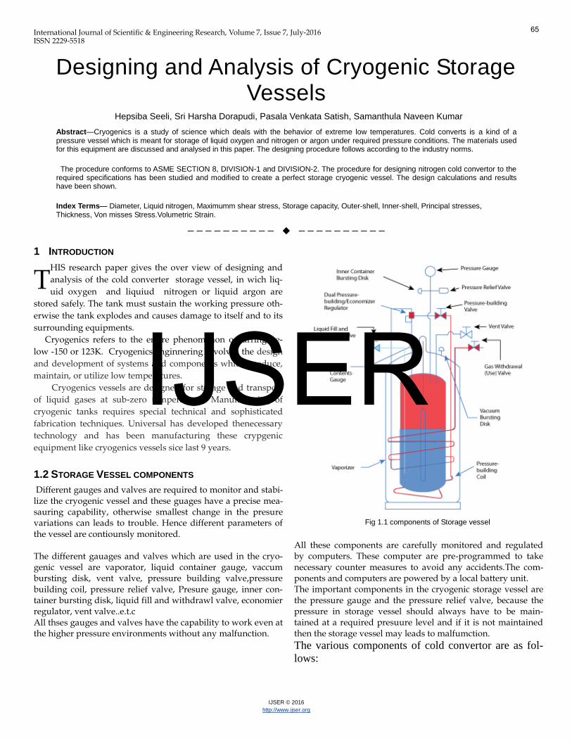
The different gauages and valves which are used in the cryo-genic vessel are vaporator, liquid container gauge, vaccum bursting disk, vent valve, pressure building valve,pressure building coil, pressure relief valve, Presure gauge, inner con-tainer bursting disk, liquid fill and withdrawl valve, economier regulator, vent valve..e.t.c All thses gauges and valves have the capability to work even at the higher pressure environments without any malfunction.
Fig 1.1 components of Storage vessel
All these components are carefully monitored and regulated by computers. These computer are pre-programmed to take necessary counter measures to avoid any accidents.The com-ponents and computers are powered by a local battery unit. The important components in the cryogenic storage vessel are the pressure gauge and the pressure relief valve, because the pressure in storage vessel should always have to be main-tained at a required presuure level and if it is not maintained then the storage vessel may leads to malfumction.
The various components of cold convertor are as fol-
lows:
T
65
IJSER
International Journal of Scientific & Engineering Research Volume 7, Issue 7, July -2016 ISSN 2229-5518
IJSER © 2016
http://www.ijser.org
Shells
The shells of cold converter are of cylindrical
sections. These are mainly two shells named as inner shells and
outer shells. The inner shell is made up of stainless steel where
as the outer shell is made up of carbon steel. The annular space
between the shells is evacuated and is perlite insulation.
Dished ends
These form the end closer to cold converters. In
the dished ends a sudden change in direction is avoided at the
junction of cylindrical shell and formed end with a gradual
change n shape reduces the local discontinuity stresses at the
junction. The dished end may be hemi-spherical, tori-spherical
or ellipsoidal.
Skirt
It provides support to the entire vessel. The skirt is usually
welded directly to the vessel either to the bottom dished end or
outside of the cylindrical shell. The bottom of the skirt of the
cold converter must be securely anchored to the concrete
foundation by means of anchor bolts embedded in the concrete
to prevent overhauling from the bending moments induced by
wind and seismic loads.
Nozzles
Nozzles are connections through which the vessel is
connected to the piping instrumentation and other control
equipment. These are welded to the shell. Nozzles can be from
seamless pipes, forged hallow bars. These are connected by
means of flanges, screw type connections or directly welded.
Pressurization coil
The unit consists of aluminum star fins by the side of
tank and is gravity fed by valve and the desired pressure can
be obtained. Its output is controlled by the regulator (pressure
control valve).
Control cabinet
The valves gauges and fittings required for the operat-
ing the convertor are located in light alloy shelter mounted on
the outer shell. For example: vacuum gauge, rupture disc, inlet
and outlet valves etc.
1.3 Structure of Cryogenic Storage vessel
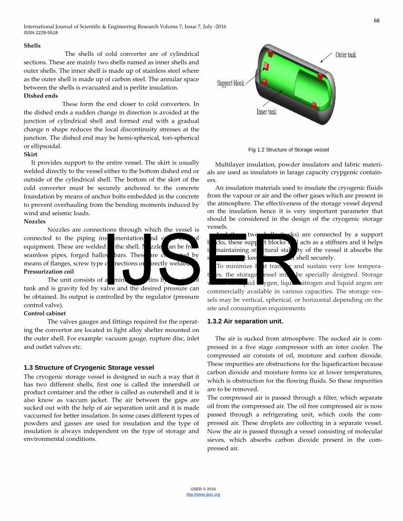
The cryogenic storage vessel is designed in such a way that it has two different shells, first one is called the innershell or product container and the other is called as outershell and it is also know as vaccum jacket. The air between the gaps are sucked out with the help of air separation unit and it is made vaccumed for better insulation. In some cases different types of powders and gasses are used for insulation and the type of insulation is always independent on the type of storage and environmental conditions.
Fig 1.2 Structure of Storage vessel
Multilayer insulation, powder insulators and fabric materi-
als are used as insulators in larage capacity crypgenic contain-ers.
An insulation materials used to insulate the cryogenic fluids from the vapour or air and the other gases which are present in the atmosphere. The effectiveness of the storage vessel depend on the insulation hence it is very important parameter that should be considered in the design of the cryogenic storage vessels.
And these two shells (tanks) are connected by a support blocks, these support blocks will acts as a stiffners and it helps in maintaining structural stability of the vessel it absorbs the stresses and it keep the product shell securely.
To minimize heat transfer and sustain very low tempera-
tures, the storage vessel must be specially designed. Storage
vessels for liquid oxygen, liquid nitrogen and liquid argon are
commercially available in various capacities. The storage ves-
sels may be vertical, spherical, or horizontal depending on the
site and consumption requirements
1.3.2 Air separation unit.
The air is sucked from atmosphere. The sucked air is com-
pressed in a five stage compressor with an inter cooler. The
compressed air consists of oil, moisture and carbon dioxide.
These impurities are obstructions for the liqueficaction because
carbon dioxide and moisture forms ice at lower temperatures,
which is obstruction for the flowing fluids. So these impurities
are to be removed.
The compressed air is passed through a filter, which separate
oil from the compressed air. The oil free compressed air is now
passed through a refrigerating unit, which cools the com-
pressed air. These droplets are collecting in a separate vessel.
Now the air is passed through a vessel consisting of molecular
sieves, which absorbs carbon dioxide present in the com-
pressed air.
66
IJSER
International Journal of Scientific & Engineering Research Volume 7, Issue 7, July -2016 ISSN 2229-5518
IJSER © 2016
http://www.ijser.org
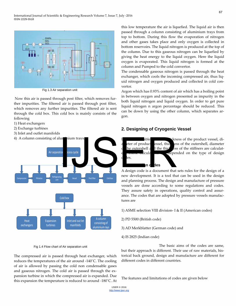
Fig 1.3 Air separation unit
Now this air is passed through post filter, which removes fur-
ther impurities. The filtered air is passed through post filter,
which removes any further impurities. The filtered air is sent
through the cold box. This cold box is mainly consists of the
following
1) Heat exchangers
2) Exchange turbines
3) Inlet and outlet manifolds
4) A column consisting of aluminium trays.
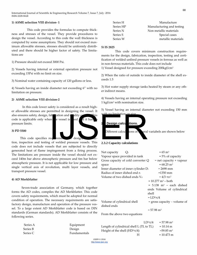
Air separation process cycle
Compression FiltrationRefrigerating
unitVessel Post filter Cold box
Cold box
Heat exchangers
Expansion turbines
Inlet and out let manifolds
A column consisting of
aluminium rays
Fig 1.4 Flow chart of Air separation unit
The compressed air is passed through heat exchanger, which
reduces the temperatures of the air around -140˚C. The cooling
of air is allowed by passing the cold non condensable gases
and gaseous nitrogen. The cold air is passed through the ex-
pansion turbine in which the compressed air is expanded. Due
this expansion the temperature is reduced to around -180˚C. At
this low temperature the air is liquefied. The liquid air is then
passed through a column consisting of aluminium trays from
top to bottom. During this flow the evaporation of nitrogen
and other gases takes place and only oxygen is collected in
bottom reservoirs. The liquid nitrogen is produced at the top of
the column. Due to this gaseous nitrogen can be liquefied by
giving the heat energy to the liquid oxygen. Here the liquid
oxygen is evaporated. This liquid nitrogen is formed at the
column and Pumped to the cold convertor. The condensable gaseous nitrogen is passed through the heat
exchanger, which cools the incoming compressed air, thus liq-
uid nitrogen and oxygen produced and collected in cold con-
vertor.
Argon which has 0.93% content of air which has a boiling point
in between oxygen and nitrogen presented as impurity in the
both liquid nitrogen and liquid oxygen. In order to get pure
liquid nitrogen n argon percentage should be reduced. This
can be down by using the other column, which separates ar-
gon.
2. Designing of Cryogenic Vessel
Different variables like the thickness of the product vessel, di-ameter of product vessel, thickness of the outershell, diameter of the outershell and the thickness of the stiffners are calculat-ed. Those calculations are depended on the type of design codes.
2.2 Design codes
A design code is a document that sets rules for the design of a
new development. It is a tool that can be used in the design
and planning process. The design and manufacture of pressure
vessels are done according to some regulations and codes.
They assure safety in operations, quality control and assur-
ance. The codes that are adopted by pressure vessels manufac-
tures are
1) ASME selection VIII division- I & II (American codes)
2) PD 5500 (British code)
3) AD Merkblatter (German code) and
4) IS 2825 (Indian code)
The basic aims of the codes are same,
but their approach is different. Their use of raw materials, his-
torical back ground, design and manufacture are different for
different codes in different countries.
The features and limitations of codes are given below
67
IJSER
International Journal of Scientific & Engineering Research Volume 7, Issue 7, July -2016 ISSN 2229-5518
IJSER © 2016
http://www.ijser.org
1) ASME selection VIII division- 1
This code provides the formulas to compute thick-
ness and stresses of the vessel. They provide procedures to
design the vessel. According to this code the wall thickness is
computed by some assumptions. They should not exceed max-
imum allowable stresses, stresses should be uniformly distrib-
uted and there should be higher factor of safety. The limita-
tions are
1) Pressure should not exceed 3000 Psi.
2) Vessels having internal or external operation pressure not
exceeding 15Psi with no limit on size.
3) Nominal water containing capacity of 120 gallons or less.
4) Vessels having an inside diameter not exceeding 6” with no
limitation on pressure.
2) ASME selection VIII division-2
In this code lower safety is considered as a result high-
er allowable stresses are permitted in designing the vessel. It
also ensures safety, design, fabrication and quality control. This
code is applicable only when the vessel is fixed and it has no
pressure limits.
3) PD 5500
This code specifies requirements for design, construc-
tion, inspection and testing of welded pressure vessels. This
code does not include vessels that are subjected to directly
generated heat of flame impingement from a firing process.
The limitations are pressure inside the vessel should not ex-
ceed 140m bar above atmospheric pressure and 6m bar below
atmospheric pressure. It is not applicable for low pressure and
single vertical axis of revolution, multi layer vessels, and
transport pressure vessel.
4) AD Merkblatter
Seven-trade association of Germany, which together
forms the AD codes, compiles the AD Merkblatter. This code
covers safety requirements, which must be adopted for normal
condition of operation. The necessary requirements are satis-
factory design, manufacture and operation of the pressure ves-
sel. To a large extent AD Merkblatter code is based on DIN
standards (German standards). AD Merkblatter consists of the
following series.
Series A Equipment
Series B Design
Series C Fundamentals
Series H Manufacture
Series HP Manufacturing and testing
Series N Non metallic materials
Series S Special cases
Series W metallic materials
5) IS 2825
This code covers minimum construction require-
ments for the design, fabrication, inspection, testing and certi-
fication of welded unfired pressure vessels in ferrous as well as
in non-ferrous materials. This code does not include
1) Vessel designed for pressure exceeding 200kgf/cm2
2) When the ratio of outside to inside diameter of the shell ex-
ceeds 1.5
3) Hot water supply storage tanks heated by steam or any oth-
er indirect means.
4) Vessels having an internal operating pressure not exceeding
1 kgf/cm2 with nomination size.
5) Vessel having an internal diameter not exceeding 150 mm
with no limitation on size
2.3 Design calculations.
Different calculations of several variabels are shown below
2.3.2 Capacity calculations
Net capacity Q1 = 65 m3
Vapour space provided in tank = 5% of capacity
Gross capacity of cold converter Q = net capacity + vapour
space = 68.25 m3
Inner diameter of inner cylinder Di = 2698 mm
Radius of inner dished end ri =1350 mm
Volume of two dished ends Vd = 4/3 πri3
= 10.277 m3 – both
= 5.138 m3 – each dished
ends Volume of cylindrical
shell
= LD2π/4
Volume of cylindrical shell = gross capacity – volume of
dished ends
= 57.98 m3
From the above two equations
LD2π/4 = 57.98 m3
Length of cylindrical shell L (TL to TL) = 10.14 m
Height of the shell (HD2π/4) =59.85 m3
H = 10.473 m
68
IJSER
International Journal of Scientific & Engineering Research Volume 7, Issue 7, July -2016 ISSN 2229-5518
IJSER © 2016
http://www.ijser.org
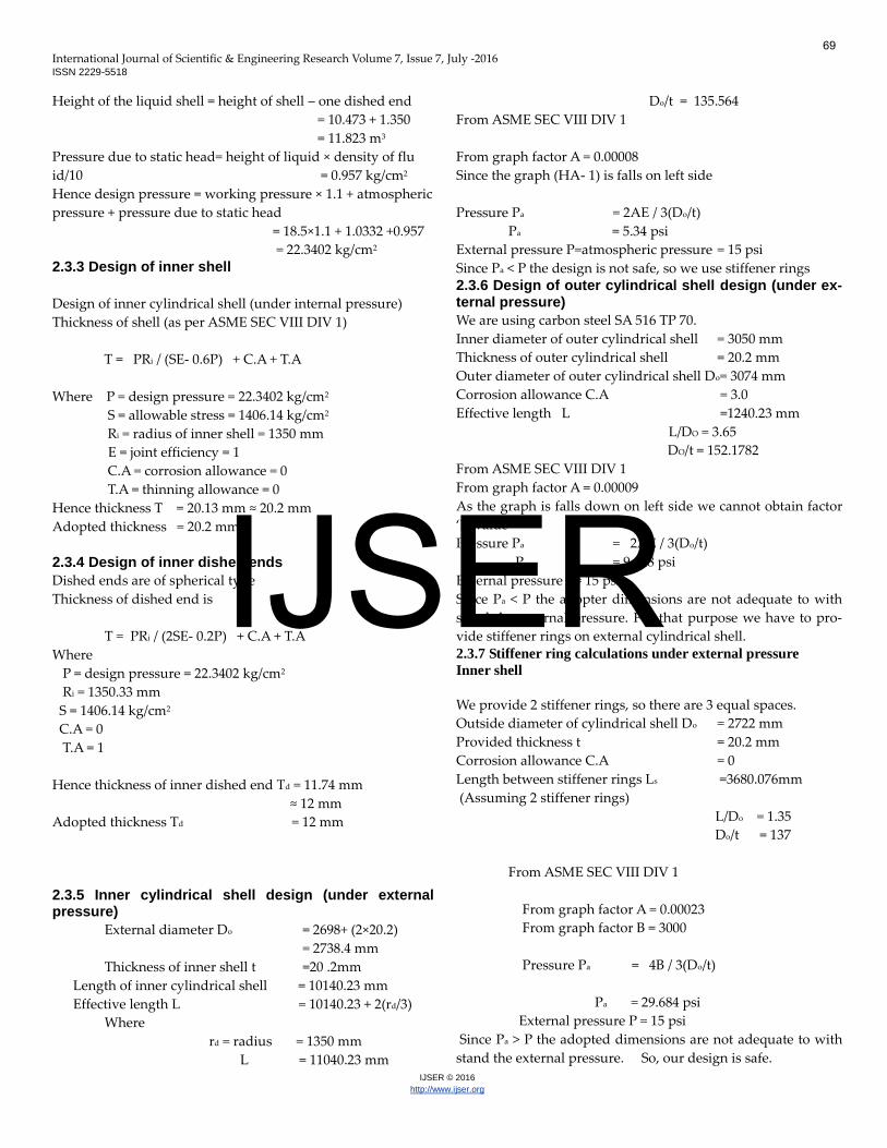
Height of the liquid shell = height of shell – one dished end
= 10.473 + 1.350
= 11.823 m3
Pressure due to static head= height of liquid × density of flu
id/10 = 0.957 kg/cm2
Hence design pressure = working pressure × 1.1 + atmospheric
pressure + pressure due to static head
= 18.5×1.1 + 1.0332 +0.957
= 22.3402 kg/cm2 2.3.3 Design of inner shell
Design of inner cylindrical shell (under internal pressure)
Thickness of shell (as per ASME SEC VIII DIV 1)
T = PRi / (SE- 0.6P) + C.A + T.A
Where P = design pressure = 22.3402 kg/cm2
S = allowable stress = 1406.14 kg/cm2
Ri = radius of inner shell = 1350 mm
E = joint efficiency = 1
C.A = corrosion allowance = 0
T.A = thinning allowance = 0
Hence thickness T = 20.13 mm ≈ 20.2 mm
Adopted thickness = 20.2 mm
2.3.4 Design of inner dished ends
Dished ends are of spherical type
Thickness of dished end is
T = PRi / (2SE- 0.2P) + C.A + T.A
Where
P = design pressure = 22.3402 kg/cm2
Ri = 1350.33 mm
S = 1406.14 kg/cm2
C.A = 0
T.A = 1
Hence thickness of inner dished end Td = 11.74 mm
≈ 12 mm
Adopted thickness Td = 12 mm
2.3.5 Inner cylindrical shell design (under external pressure)
External diameter Do = 2698+ (2×20.2)
= 2738.4 mm
Thickness of inner shell t =20 .2mm
Length of inner cylindrical shell = 10140.23 mm
Effective length L = 10140.23 + 2(rd/3)
Where
rd = radius = 1350 mm
L = 11040.23 mm
Do/t = 135.564
From ASME SEC VIII DIV 1
From graph factor A = 0.00008
Since the graph (HA- 1) is falls on left side
Pressure Pa = 2AE / 3(Do/t)
Pa = 5.34 psi
External pressure P=atmospheric pressure = 15 psi
Since Pa < P the design is not safe, so we use stiffener rings 2.3.6 Design of outer cylindrical shell design (under ex-ternal pressure)
We are using carbon steel SA 516 TP 70.
Inner diameter of outer cylindrical shell = 3050 mm
Thickness of outer cylindrical shell = 20.2 mm
Outer diameter of outer cylindrical shell Do= 3074 mm
Corrosion allowance C.A = 3.0
Effective length L =1240.23 mm
L/DO = 3.65
DO/t = 152.1782
From ASME SEC VIII DIV 1
From graph factor A = 0.00009
As the graph is falls down on left side we cannot obtain factor
‘B’ value
Pressure Pa = 2AE / 3(Do/t)
Pa = 9.448 psi
External pressure P= 15 psi
Since Pa < P the adopter dimensions are not adequate to with
stand the external pressure. For that purpose we have to pro-
vide stiffener rings on external cylindrical shell.
2.3.7 Stiffener ring calculations under external pressure
Inner shell
We provide 2 stiffener rings, so there are 3 equal spaces.
Outside diameter of cylindrical shell Do = 2722 mm
Provided thickness t = 20.2 mm
Corrosion allowance C.A = 0
Length between stiffener rings Ls =3680.076mm
(Assuming 2 stiffener rings)
L/Do = 1.35
Do/t = 137
From ASME SEC VIII DIV 1
From graph factor A = 0.00023
From graph factor B = 3000
Pressure Pa = 4B / 3(Do/t)
Pa = 29.684 psi
External pressure P = 15 psi
Since Pa > P the adopted dimensions are not adequate to with
stand the external pressure. So, our design is safe.
69
IJSER
International Journal of Scientific & Engineering Research Volume 7, Issue 7, July -2016 ISSN 2229-5518
IJSER © 2016
http://www.ijser.org
Outer shell
Outside diameter of cylindrical shell Do =3074 mm
Provided thickness t = 20.2
mm
Corrosion allowance C.A = 3 mm
Length between stiffener rings Ls = 3740 mm
L/Do = 1.218
Do/t = 152.17
From ASME SEC VIII DIV 1
From graph factor A = 0.00025
From graph factor B = 3400
Pressure Pa = 4B / 3(Do/t)
Pa = 29.79 psi
External pressure P = 15 psi
Since Pa > P the adopted dimensions are not adequate
to with stand the external pressure. So, our design is
safe.Under this geometry conditions the vessel is designed.
Some dimensions are calculated while some others are as-
sumed and some others are taken from design standard codes
and graphs
3 CRYOGENIC MATERIALS
Austenitic steels, stainless steels, fine grain
double normalized and tempered nickel steels, copper and
aluminum are excellent materials, which can be withstand cry-
ogenic temperature.
Stainless steels
Austenitic stainless steels are suited
for cryogenic applications as they remain tough and ductile
even at -269°C.
9% Nickel steels
9% nickel steels are usually classified as
ferrite steel however this constitutes austenitic ferrite and
magnetite. The presence of austenitic has given excellent
strength and resistance to brittle fracture.
The decrease in ductility with decrease
in temperature below zero is very gradual and as chirpy v
notch values are above 25 Ft lbs (346 or 4.4 kg/cm2) at -200°C.
In case of fabrication proven safety and favorable cost has
made it widely used material ins cryogenic equipment for stor-
ing and transporting liquefied gases such as Nitrogen, Me-
thane and Ethylene.
Extensive tests to destructions are carried out on tanks filled
with liquid nitrogen have demonstrated that quenching and
tempering and that post weld treatment was not beneficial.
ASME code specified that it is not necessary to post weld, heat
treatment up to and including 2 inches thickness (up to about
50mm). Aluminium alloys
Aluminium alloys like 5083 (Mg
0.445%, Mn 0.6% and cr 0.15%), 6003 (Mn 1.26% and Cu 0.12%)
are used in manufacture of cryogenic storage vessel, columns
in air separation plant and brazed aluminium of heat exchang-
ers. These show no ductile to brittle transformation even down
to the temperature of liquid helium i.e., -269°C.
The toughness properties of aluminium
are so well known that it was not considered necessary to spec-
ify the minimum value in ASME or ASTM codes. Notched
yield ratio, tear resistance, critical stress intensity is high. Fa-
tigue strength also increases with decrease in temperature. Copper alloys
Copper alloys like alpha brass and
phosphorous-di-oxide, copper were easy material of construc-
tion for cryogenic equipments. Even today copper tubes are
used for trays in small air separation plants. Copper has low
yield strength in annealed condition. Copper alloys have lesser
yield strength when compared to steel and are unaffected by
temperature changes.
Alluminum and Nickel steels are better suitable for produc-
tion of the cryogenic storage vessel hence in order to select one stress analysis should be done on both materials and the based on the stress analysis results we can select a material which is best suited for the cryogenic tank production. And that materi-al is later discussed in conclusion
4 DESIGN ANALYSIS OF CRYOGENIC VESSEL.
The first simualation is done on the cryogenic vessel which is made up of with the aluminium 5083. And its simulation re-sults are shown below 4.2 Simulation: 1
Analyzed File: Cryogenic vessel
Autodesk Inventor Version: 2015 (Build 190159000, 159)
Creation Date: 15-May-16, 10:50 PM
Simulation Author: Pasala Venkata Satish
Project Info (iProperties)
Author Pasala Venkata Satish
Part Number 2ndcc
Designer Pasala Venkata Satish
Date Created 07-May-16
70
IJSER
International Journal of Scientific & Engineering Research Volume 7, Issue 7, July -2016 ISSN 2229-5518
IJSER © 2016
http://www.ijser.org
Physical
Material Aluminum 5083 87 Cold Formed
Density 0.0960986 lbmass/in^3
Mass 31879.8 lbmass
Area 4762870 cm^2
Volume 5436260 cm^3
Center of Gravity x=-0.0000000000029165 cm y=-525.627 cm
z=-154.6 cm
Note: Physical values could be different from Physical values
used by FEA reported below.
General objective and settings:
Design Objective Single Point
Simulation Type Static Analysis
Last Modification Date 15-May-16, 10:45 PM
Detect and Eliminate Rigid Body
Modes No
Mesh settings:
Avg. Element Size (fraction of model diameter) 0.1
Min. Element Size (fraction of avg. size) 0.2
Grading Factor 1.5
Max. Turn Angle 60 deg
Create Curved Mesh Elements Yes
Material(s)
Name Aluminum 5083 87 Cold Formed
General
Mass Density 0.0960986
lbmass/in^3
Yield Strength 41335.8 psi
Ultimate Tensile
Strength 55839.5 psi
Stress
Young's Modulus 10007.6 ksi
Poisson's Ratio 0.33 ul
Shear Modulus 3762.26 ksi
Part
Name(s) Cryogenic Vessel
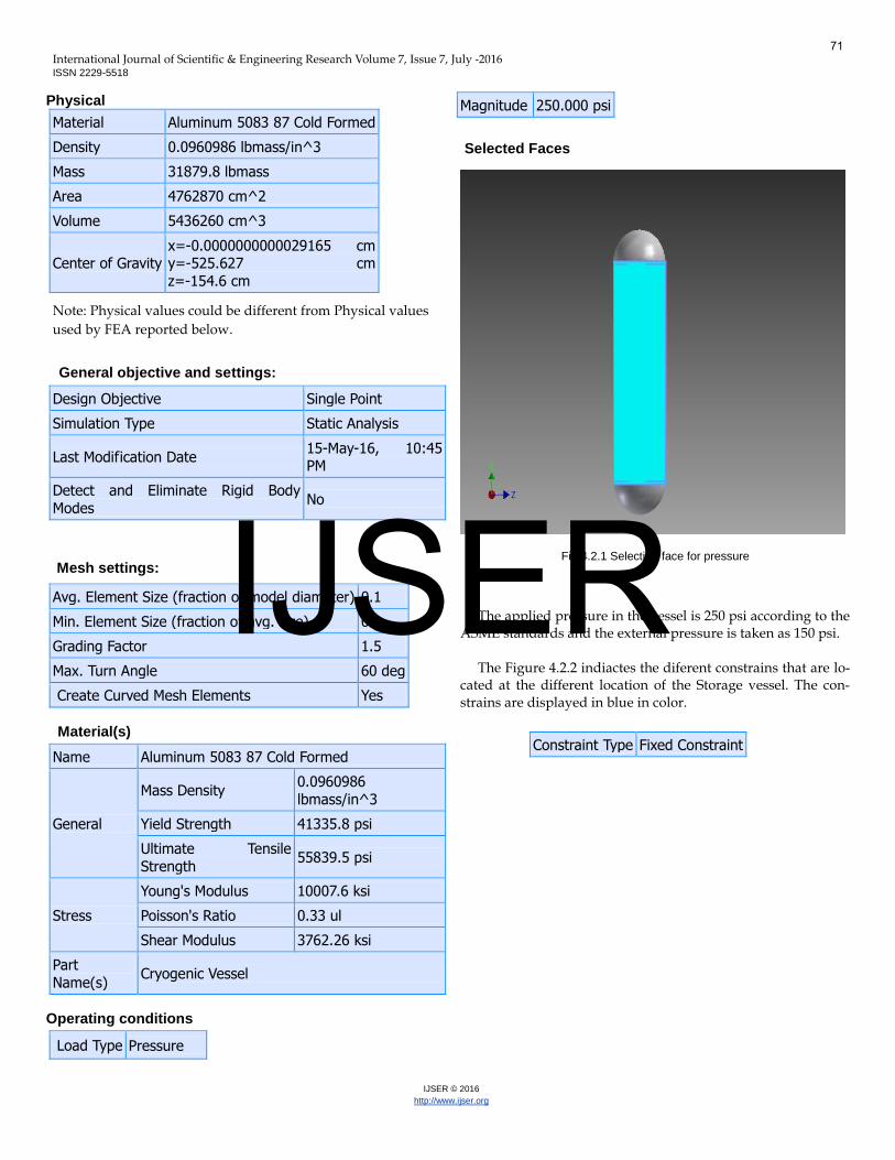
Operating conditions
Load Type Pressure
Magnitude 250.000 psi
Selected Faces
Fig 4.2.1 Selecting face for pressure
The applied pressure in the vessel is 250 psi according to the ASME standards and the external pressure is taken as 150 psi.
The Figure 4.2.2 indiactes the diferent constrains that are lo-
cated at the different location of the Storage vessel. The con-strains are displayed in blue in color.
Constraint Type Fixed Constraint
71
IJSER

International Journal of Scientific & Engineering Research Volume 7, Issue 7, July -2016 ISSN 2229-5518
IJSER © 2016
http://www.ijser.org
Fig 4.2.2 constrained position in vessel for analysis
Result Summary
Name Minimum Maximum
Volume 5.43626E+009 mm^3
Mass 31879.8 lbmass
Von Mises Stress
0.000866688 MPa 117.146 MPa
1st Principal
Stress -23.4491 MPa 89.0687 MPa
3rd Principal
Stress -125.807 MPa 53.9125 MPa
Displacement 0 mm 2.4775 mm
Safety Factor 2.43287 ul 15 ul
Stress XX -125.806 MPa 77.8312 MPa
Stress XY -39.6739 MPa 36.9261 MPa
Stress XZ -64.459 MPa 61.6759 MPa
Stress YY -79.1859 MPa 58.5517 MPa
Stress YZ -36.8943 MPa 30.912 MPa
Stress ZZ -124.757 MPa 78.149 MPa
X Displacement -2.2528 mm 2.20901 mm
Y Displacement -1.06415 mm 1.02019 mm
Z Displacement -2.26653 mm 2.32907 mm
Equivalent Strain
0.0000000141568 ul
0.00152525 ul
1st Principal Strain
-0.000021337 ul 0.000974366 ul
3rd Principal
Strain -0.00168837 ul
0.0000616597
ul
Strain XX -0.00164065 ul 0.000974262
ul
Strain XY -0.000764729 ul 0.000711764 ul
Strain XZ -0.00124247 ul 0.00118883 ul
Strain YY -0.00124163 ul 0.000576865 ul
Strain YZ -0.000711151 ul 0.00059584 ul
Strain ZZ -0.0016662 ul 0.000855221 ul
ContactPressure 0 MPa 8.51499 MPa
ContactPressure
X -1.67133 MPa 1.55096 MPa
ContactPressure
Y -0.00151738 MPa 8.16541 MPa
ContactPressure
Z -2.41261 MPa 1.7797 MPa
Von Mises Stress
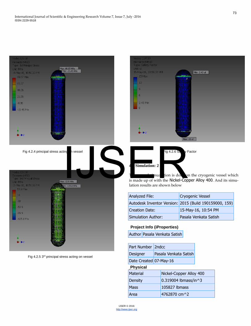
Fig 4.2.3 application of von mises stress The maximum stress produced in the vessel is 117.1 mpa
and its location is near to the welded region of the vessel. In analysis 1st principal stresses and 3rd principal stresses
are important hence those two analysis reports are also shown below. The different colors indicates the different stresses act-ing at the different locations of the vessel
72
IJSER
International Journal of Scientific & Engineering Research Volume 7, Issue 7, July -2016 ISSN 2229-5518
IJSER © 2016
http://www.ijser.org
Fig 4.2.4 principal stress acting on vessel
Fig 4.2.5 3rd principal stress acting on vessel
Fig 4.2.6 Safety Factor
4.3 Simulation: 2
The second simualation is done on the cryogenic vessel which
is made up of with the Nickel-Copper Alloy 400. And its simu-lation results are shown below
Analyzed File: Cryogenic Vessel
Autodesk Inventor Version: 2015 (Build 190159000, 159)
Creation Date: 15-May-16, 10:54 PM
Simulation Author: Pasala Venkata Satish
Project Info (iProperties)
Author Pasala Venkata Satish
Part Number 2ndcc
Designer Pasala Venkata Satish
Date Created 07-May-16
Physical
Material Nickel-Copper Alloy 400
Density 0.319004 lbmass/in^3
Mass 105827 lbmass
Area 4762870 cm^2
73
IJSER
International Journal of Scientific & Engineering Research Volume 7, Issue 7, July -2016 ISSN 2229-5518
IJSER © 2016
http://www.ijser.org
Volume 5436260 cm^3
Center of Gravity
x=-0.0000000000029165 cm
y=-525.627 cm z=-154.6 cm
Note: Physical values could be different from Physical values
used by FEA reported below.
General objective and settings:
Design Objective Single Point
Simulation Type Static Analysis
Last Modification Date 15-May-16,
10:53 PM
Detect and Eliminate Rigid Body Modes
No
Mesh settings:
Avg. Element Size (fraction of
model diameter) 0.1
Min. Element Size (fraction of avg. size)
0.2
Grading Factor 1.5
Max. Turn Angle 60 deg
Create Curved Mesh Elements Yes
Material(s):
Name Nickel-Copper Alloy 400
General
Mass Density 0.319004 lbmass/in^3
Yield Strength 31908.3 psi
Ultimate Tensile
Strength 80931.1 psi
Stress
Young’s Modulus 26005.3 ksi
Poisson’s Ratio 0.315 ul
Shear Modulus 9887.93 ksi
Part Name(s)
Cryogenic vessel
Operating conditions:
Load Type Pressure
Magnitude 250.000 psi
The body contacts along with selected faces are same for the
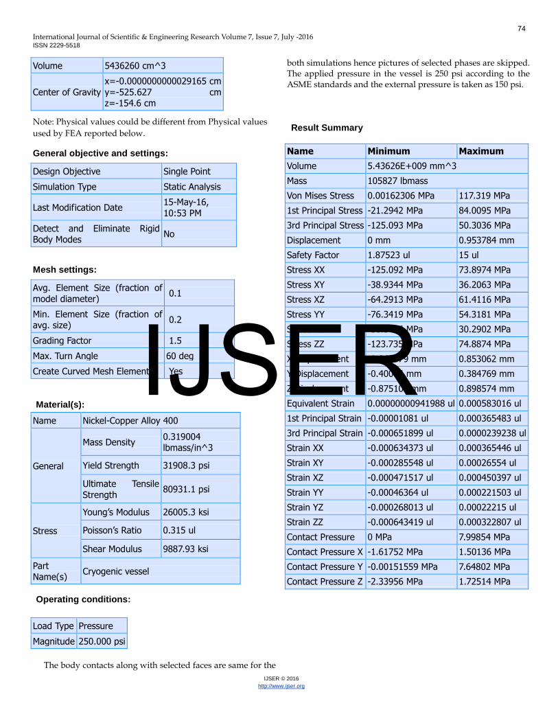
both simulations hence pictures of selected phases are skipped. The applied pressure in the vessel is 250 psi according to the ASME standards and the external pressure is taken as 150 psi.
Result Summary
Name Minimum Maximum
Volume 5.43626E+009 mm^3
Mass 105827 lbmass
Von Mises Stress 0.00162306 MPa 117.319 MPa
1st Principal Stress -21.2942 MPa 84.0095 MPa
3rd Principal Stress -125.093 MPa 50.3036 MPa
Displacement 0 mm 0.953784 mm
Safety Factor 1.87523 ul 15 ul
Stress XX -125.092 MPa 73.8974 MPa
Stress XY -38.9344 MPa 36.2063 MPa
Stress XZ -64.2913 MPa 61.4116 MPa
Stress YY -76.3419 MPa 54.3181 MPa
Stress YZ -36.5436 MPa 30.2902 MPa
Stress ZZ -123.735 MPa 74.8874 MPa
X Displacement -0.868379 mm 0.853062 mm
Y Displacement -0.40084 mm 0.384769 mm
Z Displacement -0.875101 mm 0.898574 mm
Equivalent Strain 0.00000000941988 ul 0.000583016 ul
1st Principal Strain -0.00001081 ul 0.000365483 ul
3rd Principal Strain -0.000651899 ul 0.0000239238 ul
Strain XX -0.000634373 ul 0.000365446 ul
Strain XY -0.000285548 ul 0.00026554 ul
Strain XZ -0.000471517 ul 0.000450397 ul
Strain YY -0.00046364 ul 0.000221503 ul
Strain YZ -0.000268013 ul 0.00022215 ul
Strain ZZ -0.000643419 ul 0.000322807 ul
Contact Pressure 0 MPa 7.99854 MPa
Contact Pressure X -1.61752 MPa 1.50136 MPa
Contact Pressure Y -0.00151559 MPa 7.64802 MPa
Contact Pressure Z -2.33956 MPa 1.72514 MPa
74
IJSER
International Journal of Scientific & Engineering Research Volume 7, Issue 7, July -2016 ISSN 2229-5518
IJSER © 2016
http://www.ijser.org
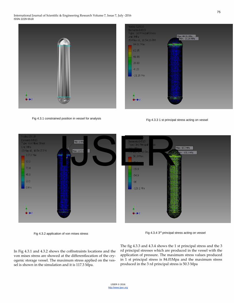
Fig 4.3.1 constrained position in vessel for analysis
Fig 4.3.2 application of von mises stress
In Fig 4.3.1 and 4.3.2 shows the coffnstraints locations and the von mises stress are showed at the differentlocation of the cry-ogenic storage vessel. The maximum stress applied on the ves-sel is shown in the simulation and it is 117.3 Mpa.
Fig 4.3.3 1 st principal stress acting on vessel
Fig 4.3.4 3rd principal stress acting on vessel
The fig 4.3.3 and 4.3.4 shows the 1 st principal stress and the 3 rd principal stresses which are produced in the vessel with the application of pressure. The maximum stress values produced in 1 st principal stress is 84.01Mpa and the maximum stress produced in the 3 rd principal stress is 50.3 Mpa
75
IJSER
International Journal of Scientific & Engineering Research Volume 7, Issue 7, July -2016 ISSN 2229-5518
IJSER © 2016
http://www.ijser.org
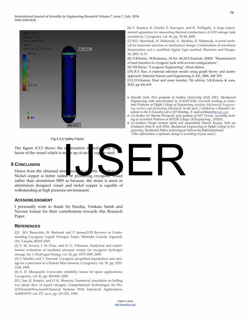
Fig 4.3.5 Safety Factor
The figure 4.3.5 shows the information regarding the safety factor of the vessel which is made up of nickel copper steel.
5 CONCLUSION
Hence from the obtained stress analysis reports it is clear that Nickel copper is better suited of producing cryogenic vessel rather than aluminium 5083 as because, the strain is more in aluminium designed vessel and nickel copper is capable of withstanding at high pressure environment.
ACKNOWLEDGMENT
I personally wish to thank Sri Harsha, Venkata Satish and Naveen kumar for their contributions towards this Research Paper.
REFERENCES
[[1] M.I. Baracaldo, W. Bertrand and P. Jensen,IVIS Reviews in Under-
standing Cryogenic Liquid Nitrogen Tanks, Minitube Canada, Ingersoll,
ON, Canada, R0107.0507.
[2] S. M. Aceves, J. M. Frias, and O. G. Villazana, Analytical and experi-
mental evaluation of insulated pressure vessels for cryogenic hydrogen
storage, Int. J. Hydrogen Energy, vol. 25, pp. 1075-1085, 2000.
[3] P. Mueller and T. Durrant, Cryogenic propellant liquefaction and stor-
age for a precursor to a human Mars mission, Cryogenics, vol. 39, pp. 1021-
1028, 1999.
[4] E. D. Marquardt, Cryocooler reliability issues for space applications,
Cryogenics, vol. 41, pp. 845-849, 2002.
[5] I. Jun, K. Kenjiro, and O. K. Mamoru, Numerical simulation on boiling
two phase flow of liquid nitrogen, Computational Technologies for Flu-
id/Thermal/Structural/Chemical Systems With Industrial Applications,
ASME/PVP, vol. 377, no.2, pp. 219-225, 1998.
[6] S. Kamiya, K. Onishi, E. Kawagoe, and K. Nishigaki, A large experi-
mental apparatus for measuring thermal conductance of LH2 storage tank
insulations, Cryogenics, vol. 40, pp. 35-44, 2000.
[7] B.D. Manshadi, H. Mahmudi, A. Abedian, R. Mahmudi, A novel meth-
od for materials selection in mechanical design: Combination of non-linear
linearization and a modified digital logic method, Materials and Design,
28, 2007, 8–15.
[8] O.Khemis. M.Boumaza, M.Ait Ali,M.X.Francois (2004) “Measurement
of heat transfers in cryogenic tank with several configurations”.
[9] TM Flynn, “Cryogenic Engineering”, third edition.
[10] R.V. Rao, A material selection model using graph theory and matrix
approach, Material Science and Engineering A, 431, 2006, 248–255.
[11] D.S.Kumar, Heat and mass transfer, 7th edition, S.K.Kataria & sons,
2010, pp 436-439.
Hepsiba Seeli, Post graduate of Andhra University (AU) 2011, Mechanical
Engineering with specialization in (CAD/CAM). Currentl working as Assis-tant Professor at Pydah College of Engineering teaching Mechanical Engineer-ing courses and facilitating laboratory. In the past, I worked as a Research As-sistant in the E-Foundry Lab at IIT Bombay., E-mail:[email protected]
Co-Author Sri Harsha Dorapudi, post graduae of NIT Tiruch, currently work-ing as Assistant Professor at MVGR College Of Engineering., INDIA.
Co-Authors Pasala venkata satish and samanthula Naveen Kumar, both are Graduates from B. tech 2016, Mechanical Engineering at Pydah College of En-gineering, Jawaharlal Nehru technological University Kakinada(jntuk). (This information is optional; change it according to your need.).
76
IJSER