“designing assistive technology: a personal experience of trial and error “
TRANSCRIPT

Computer Engineering
Designing Assistive Technology
Roberto Manduchi
A personal experience of trial and error

Research at JPL (circa 2000)

Research at JPL (circa 2000)
Sensors

Can we go from here …
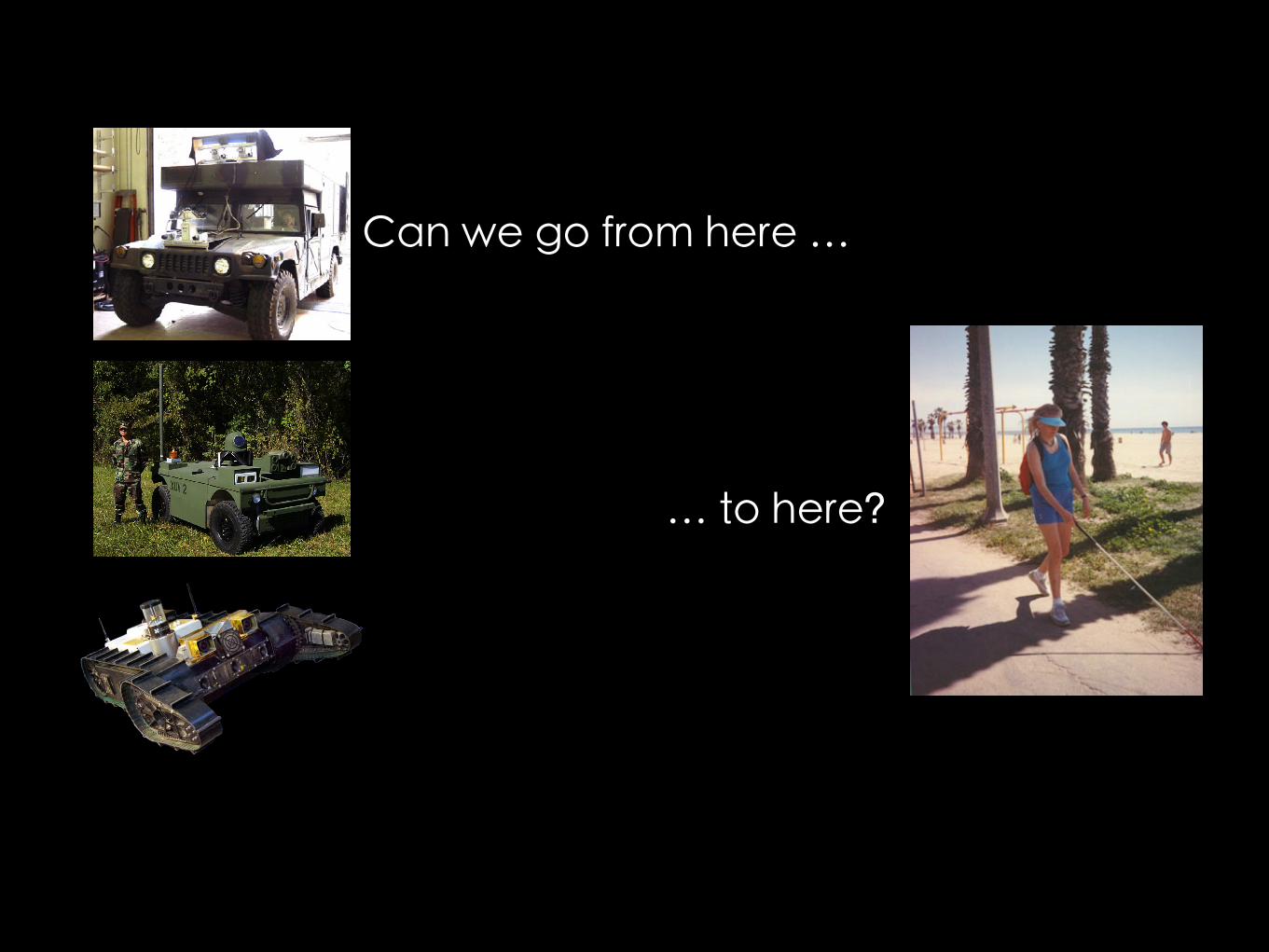
Can we go from here …
… to here?

Services that “provide equipment or systems, standardized or individualized, whose aim is to improve or maintain the functional capabilities of individuals with disabilities”.
M.J. Fuhrer, NIH
Assistive Technology:

Significant vision loss (25 million)
Normal vision
Legally blind (1.3 million)
Blind or light perception (0.25 million)
18-44
45-64
65-74
≥75
Prevalence
Age distribution

Educational attainment:
With vision loss
U.S. average
< High schoolHigh school Some collegeBachelor’s
13% 27%
23% 31% 28% 18%
Employment rate : – 19% of legally blind Americans 18 and older were employed
in 1994-95 (NHIS, 1994-95)
Pre-readers
Non-
read
ers
Aud. readers
Visual readersBr
aille
read
ers

1. You cannot drive your car2. You cannot read the paper 3. You may trip over an obstacle 4. You may miss a sign far away 5. You may not be able to cross a street safely 6. You may not find what you are looking for at the supermarket 7. You may get lost in a new place 8. You may not receive a proper education 9. You may have problems finding a job 10. You may not recognize friends from a distance 11. You may lose objects in your home 12. You may have problems surfing the Web 13. You may not know who is in the room
14. You may not be able to read this line
If you cannot see well...

Success stories
Screen readers
Screen magnifiers
Braille interfaces
Enlargers/telescopes

Success stories
Accessible GPS
Money reader
Object recognition/crowdsourcing
OCR
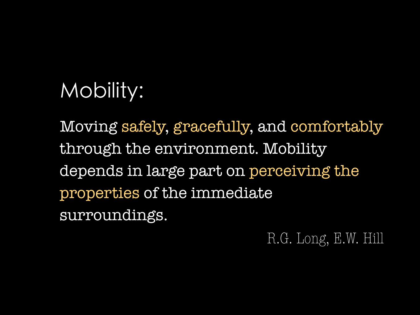
Moving safely, gracefully, and comfortably through the environment. Mobility depends in large part on perceiving the properties of the immediate surroundings.
R.G. Long, E.W. Hill
Mobility:

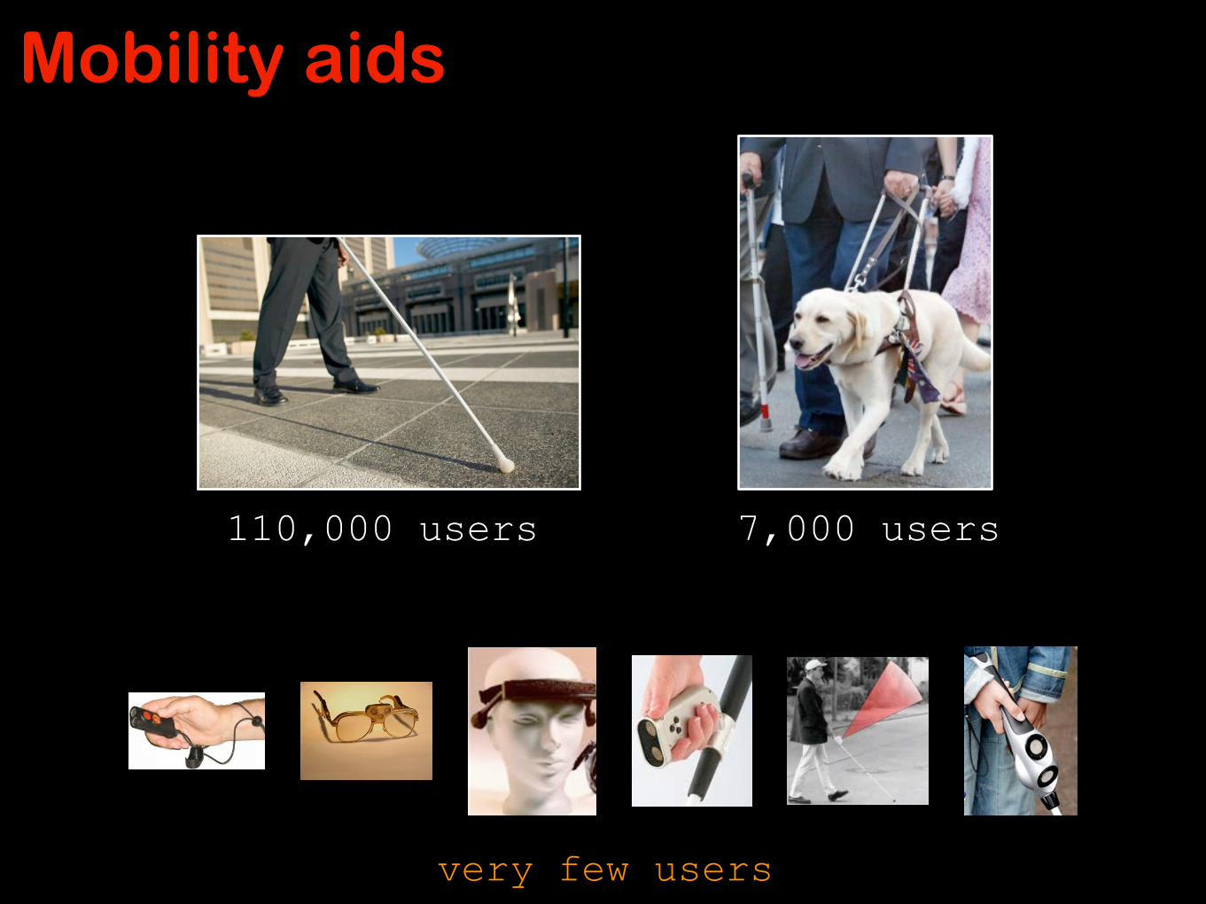
Mobility aids
110,000 users 7,000 users
Mobility aids
110,000 users 7,000 users
very few users

A laser-based virtual cane
• Active triangulation for range estimation
Camera Laserpointer
• Range tracking for environmental feature detection
D. Yuan, R. Manduchi (2005). Proc. CVPR.

The many things a white cane can do…• Bumper: contacts things that are in the direct path of travel • Probe: an extension of the sense of touch. • Finds, verifies, and discriminates landmarks • Helps establish the line of direction of travel
–e.g. by trailing a straight edge • Detects drop offs • Measurement tool
and…

The many things a white cane can do…• Bumper: contacts things that are in the direct path of travel • Probe: an extension of the sense of touch. • Finds, verifies, and discriminates landmarks • Helps establish the line of direction of travel
–e.g. by trailing a straight edge • Detects drop offs • Measurement tool
and…• Is cheap • Never runs out of power • Is light, durable, and foldable • Always works • Identifies the blind traveler • Puts drivers on alert when it moves into a street before the
blind traveler

The process of navigating through an environment and traveling to places by relatively direct paths.
R.G. Long, E.W. Hill
Finding the way is not a gift or a innate ability… it is a precondition for life itself. Knowing where I am, my location, is the precondition for knowing where I have to go, wherever it may be.
Otl Aicher
Wayfinding:

Wayfinding without sight
The Love Stone at Kiyomizu Temple, Kyoto

• Prior information –Maps –Verbal directions
• Path integration –Continuous update of egocentric coordinates of starting location
–Remembering the path traversed, turns, etc. • Piloting
–Sensing one’s positional information to determine one’s location
–Reading signs –Noticing landmarks (acoustic, tactile, smells, heat…)
Wayfinding for sighted people

• Prior information –Maps (tactile) –Verbal directions
• Path integration –Continuous update of egocentric coordinates of starting location
–Counting steps, turns, etc. • Piloting
–Sensing one’s positional information to determine one’s location
–Reading signs (Braille) –Noticing landmarks (acoustic, tactile, smells, heat…)
Wayfinding for blind people

GPS is only a partial solution
• Works only outdoors • ~10m resolution
Will take you to locations and won’t get you lost, but…
…where is the door?

• Tactile paving
• Accessible pedestrian signals
• Light beaconing (Talking Signs)
• RFID, iBeacons
• iBeacons
Supporting Infrastructure

The problem with indoor navigation systems
Turn-by turn guidance only useful if you
can visually access the scene context
Blind travelers need some form of scene knowledge – a representation of objects, spaces and surface at a scale normally not represented in maps

The promise of cameras
12 Chelhwon Kim, Roberto Manduchi
c2
c1
c1
c2
c1c2 c1
c2
Fig. 5. Top row: Coplanar line sets produced by our algorithm for the image set con-sidered in the evaluation. Only one image for each pair is shown. Di↵erent line setsare shown in di↵erent color. Note that some lines (especially those at a planar junc-tion) may belong to more than one cluster (although they are displayed using only onecolor). All lines that have been matched (possibly incorrectly) across images are shown(by thick segments) and used for coplanarity estimation. The quadrilaterals Q shownby dotted lines represent potential planar patches. They contain all coplanar lines ina cluster, and are computed as described in Sec. 4. Bottom row: 3-D reconstruction ofthe visible line segments and camera center positions. Line segment are colored accord-ing to their orientation in space. The colored rectangles are the reconstructed planarpatches corresponding to the quadrilateral Q shown with the same color as in the toprow.
can test for their coplanarity using Plucker matrices [30]. More precisely, lines(L1, L2, L3) are coplanar if L1L⇤
2L3 = 0, where L1, L3 are the Plucker L-matricesassociated with L1, L3 and L⇤
2 is the Plucker L⇤-matrix associated with L2 [30].The ability of an algorithm to determine line coplanarity is critical for precisereconstruction of Manhattan environments; in addition, this criterion gives us anindirect assessment of the quality of pose estimation (as we expect that good poseestimation should result in good 3-D reconstruction and thus correct coplanarityassessment).
We compared our algorithm against two other techniques. The first is tradi-tional structure from motion from point features (SFM-P). We used the popularVisualSFM application [31], created and made freely available by ChangchangWu. The second technique is Elqursh and Elgammal’s algorithm [7], which useslines (rather than point features) in a pair of images to estimate the relativecamera pose (SFM-L). Once the motion parameters (R, t) are obtained witheither algorithm, 3-D lines are reconstructed from matched image line pairs. Tocheck for coplanarity of a triplet of lines (at least two of which are parallel), wecompute the associated Plucker matrices L1, L⇤
2 and L3, each normalized to unitnorm (largest singular value), and threshold the norm of L1L⇤
2L3. By varyingthis threshold, we obtain a precision/recall curve. This evaluation was conductedwith and without the “corrective” pre-processing step, discussed in Sec. 4, thatrotates each line segment to align it with the associated vanishing point.
extract and localize the main planar structures in the scene from two images (see Fig. 2) with substantially higher accuracy than with traditional point-based SFM. When structural constraints such as Manhattan world can be expected, the geometry of the environment can be reconstructed even from a single image [15] [50] [33]. This relatively new approach exploits multiple visual cues and geometric constraints, to generate planar hypotheses that are then validated using heuristic criteria or via machine learning. Fig. 3 shows some examples of single-view planar reconstruction using an algorithm similar to [50]. 3-D reconstruction: Proposed work. Drawing on existing successful algorithms as described above, we will develop a system that can acquire the geometric layout of a structured environment (Manhattan world) from a single image, or from two images taken from nearby positions (as the user moves his or her head from side to side). While a detailed reconstruction of all surfaces visible in the scene would typically require processing of longer sequences, in this project component we are only concerned with finding the general layout of the walls, which can be communicated concisely and effectively in terms of basic primitives, along with any notable landmarks. Based on our previous work and preliminary experiments, several issues need to be investigated before these techniques are ready for the proposed user study described in Sec. 3.2.2. We list the specific steps planned in the following. Multi-planar reconstruction. Some of the most successful single-image reconstruction algorithms operate under the assumption that the walls, ceiling, and floor of the visible space form a cuboid. While a cuboid can properly model a standard room or corridor, more complex cases must be considered. (Note that both Fig. 2 and 3 contains some such examples.) In our preliminary work we already looked at ways to expand from a single cuboid structure to more complex multi-planar layouts (see e.g. the two rightmost images in Fig. 3). We will continue with this line of research to ensure that typical situations (which include half-occluded surfaces) are dealt with by the 3-D reconstruction algorithm. Exploiting parallax. If the user can take two pictures of the same scene from nearby viewpoints (e.g., moving his or her head by 10-20 cm side to side between the two pictures), the parallax induced by camera motion can be used to extract 3-D information (see Fig. 2). This geometry reconstruction algorithm is oblivious of the whole scene structure, which normally contains a floor, a ceiling, and a number of vertical walls. We will explore integrating the 3-D planar information from our line-based two-view reconstruction technique [43] with a structure-aware single-view reconstruction algorithm, in order to increase robustness of reconstruction. We expect this to be very useful in ambiguous situations with multiple parallel planes that are often mistakenly reconstructed as a single plane from a single view of the scene. Reconstructing scale. Monocular 3-D reconstruction is only defined up to an unknown scale factor. For example, from the first image of Fig. 3 it is impossible, without some other measurements or prior information, to estimate whether the front wall is 2 meters high and seen from a distance of 3 meters, or 3 meters high and seen from a distance of 4.5 meters. In order to infer scale, one may rely on the known height of visible structures (if available). For example, if the ceiling height is known (at least approximately), this could provide the scale information once the whole extent of a wall from floor to ceiling has been identified in the image. In the case of two-view analysis described above, the baseline (distance between the camera position in the two shots) could be estimated to some approximation by double integration of the accelerometric data collected while the user is moving their head from the first to
Figure 3. 3-D planar reconstruction from single images, using an algorithm similar to [50]. The main planar structures, automatically detected by the algorithm, are shown bordered by thick dark lines, and colored according to their orientation. (First two images from [60].)
A portable camera coupled with robust computer vision algorithms could provide spatial context…
…but how are you going to communicate spatial information?
3-D ambient reconstruction
crosswalk localization
text spotting

Scene descriptions: A proposal
• What if we could crowdsource collection of local scene descriptions in a similar way to OpenStreetMap?
• Scene descriptions could then be converted to narrative maps or to tactile maps

(Computer) Vision Without Sight

• How does a blind person operate a camera system to recognize a particular target?
• How can we design a system that takes into account the human factors associated with its use?
Reading text

Mobile OCR works well…
…when you can take a good picture of the document!
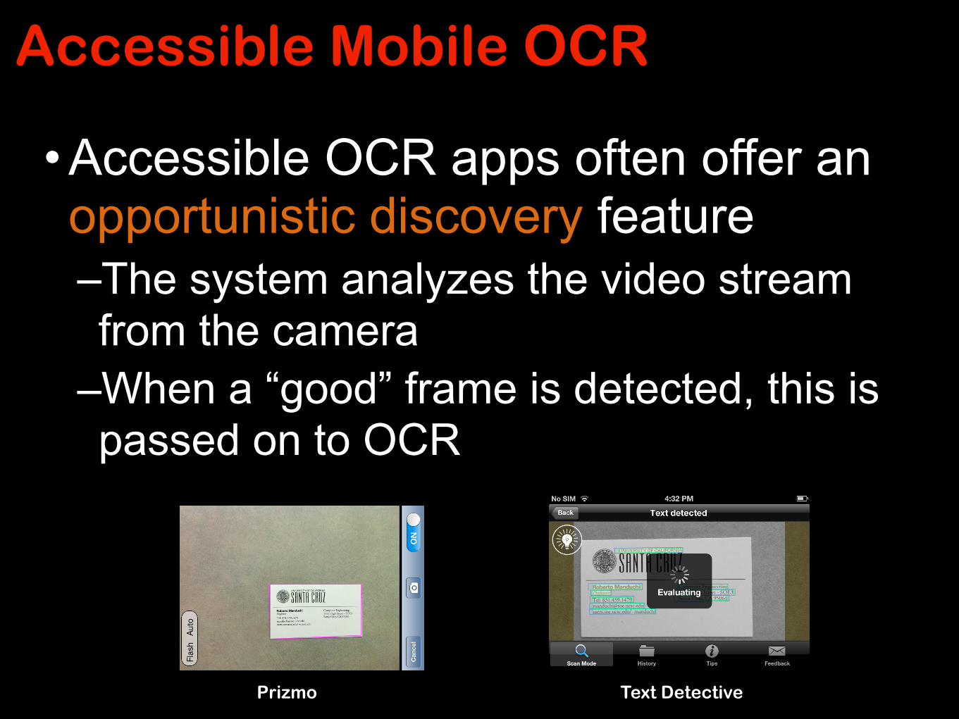
Accessible Mobile OCR
• Accessible OCR apps often offer an opportunistic discovery feature –The system analyzes the video stream from the camera
–When a “good” frame is detected, this is passed on to OCR
Prizmo Text Detective

Guided Mobile OCR
• Real-time text spotting and line detection
• Computes whether current frame is OCR-readable (enough resolution, enough margin)
• If not, produces guidance instructions (‘up’, ‘left’,…)
• Captures a high-resolution image for OCR processing

Guided OCR - results
• Without system assistance or prior training, it can be extremely difficult to acquire readable images
•Guidance is more efficient than opportunistic discovery
• By using our guidance app, our participants learnt to take better pictures – even without assistance!

Thank you