designing the sts-134 re-rendezvous: a preparation for ... · designing the sts-134 re-rendezvous:...
TRANSCRIPT

1
American Institute of Aeronautics and Astronautics
Designing the STS-134 Re-Rendezvous: A Preparation for Future Crewed Rendezvous Missions
Timothy D. Stuit United Space Alliance, LLC
Houston, TX, 77058
In preparation to provide the capability for the Orion spacecraft, also known as the Multi-Purpose Crew Vehicle (MPCV), to rendezvous with the International Space Station (ISS) and future spacecraft, a new suite of relative navigation sensors are in development and were tested on one of the final Space Shuttle missions to ISS. The National Aeronautics and Space Administration (NASA) commissioned a flight test of prototypes of the Orion relative navigation sensors on STS-134, in order to test their performance in the space environment during the nominal rendezvous and docking, as well as a re-rendezvous dedicated to testing the prototype sensors following the undocking of the Space Shuttle orbiter at the end of the mission. Unlike the rendezvous and docking at the beginning of the mission, the re-rendezvous profile replicates the newly designed Orion coelliptic approach trajectory, something never before attempted with the shuttle orbiter. Therefore, there were a number of new parameters that needed to be conceived of, designed, and tested for this re-rendezvous to make the flight test successful. Additionally, all of this work had to be integrated with the normal operations of the ISS and shuttle and had to conform to the constraints of the mission and vehicles. The result of this work is a separation and re-rendezvous trajectory design that would not only prove the design of the relative navigation sensors for the Orion vehicle, but also would serve as a proof of concept for the Orion rendezvous trajectory itself. This document presents the analysis and decision making process involved in attaining the final STS-134 re-rendezvous design.
Nomenclature ALT DAP Alternate Digital Auto-Pilot Ang Angle AZ Azimuth DAP Digital Auto-Pilot Deg Degree(s) DOF Degree of Freedom DRU Data Recording Unit DTEA Docking Torque Equilibrium Attitude DTO Detailed/Development Test Objective EDT Eastern Daylight saving Time EL Elevation EVA Extra Vehicular Activity FD Flight Day fps Feet per Second FRR Flight Readiness Review FSW Flight Software ft Feet GPS Global Positioning System
Rendezvous Design Engineer, Orbit Flight Design and Dynamics, 1150 Gemini, Houston, TX
77058/USH483L, and AIAA Senior Member - Lifetime.
https://ntrs.nasa.gov/search.jsp?R=20110014805 2020-03-26T08:43:39+00:00Z

2
American Institute of Aeronautics and Astronautics
HHL Hand Held LIDAR IMU Inertial Measurement Unit ISS International Space Station lbf pound-force km kilometer(s) LEO Low Earth Orbit LIDAR Light Detection and Ranging LVLH Local Vertical Local Horizontal coordinate frame MC Midcourse maneuver MCC Mission Control Center MET Mission Elapsed Time MMOD micro-meteoroid and orbital debris MPCV Multi-Purpose Crew Vehicle NASA National Aeronautics and Space Administration NC Catch-up or Phasing maneuver NCC Corrective Combination maneuver NH Height Adjustment maneuver nm Nautical Mile(s) NSR Slow Rate or Coelliptic maneuver OBSS Orbiter Boom Sensor System OMP Orbital Maneuver Processor OMS Orbital Maneuvering System PET Phase Elapsed Time PRCS Primary Reaction Control System prox ops proximity operations R-Bar Radius vector, positive down toward Earth center RCC Reinforced Carbon-Carbon RCS Reaction Control System rev revolution (one complete orbit) RMS Remote Manipulator System RPOP Rendezvous and Proximity Operations Program SAIL Shuttle Avionics Integration Lab SEP Separation maneuver SOR Stable Orbit Rendezvous SPOT Spacecraft Position Optimal Tracking STORRM Sensor Test for Orion Relative Navigation Risk Mitigation TCS Trajectory Control Sensor TDA Transition to Docking Axis TEA Torque Equilibrium Attitude THC Translational Hand Controller Ti Transition Initiation maneuver (used in SOR trajectory) TIG Time of Ignition TPI Terminal Phase Initiation maneuver (used in Orion coelliptic trajectory) TPS Thermal Protection System V-Bar Velocity vector, positive in the direction of orbital motion VGO Velocity to Go VNS Vision Navigation Sensor VRCS Vernier Reaction Control System X-dot, X axis translational rate ∆H Delta Height ∆V Delta Velocity σ Sigma, standard deviation
3
American Institute of Aeronautics and Astronautics
I. Introduction The Orion spacecraft, also known as the Multi-Purpose Crew Vehicle (MPCV), is NASA’s next generation of
human exploration vehicle under development to be used to send humans beyond low Earth orbit (LEO). It is also a backup to commercial human spacecraft being developed for access to the ISS. Early Orion missions are expected to rendezvous and dock with ISS. A rendezvous between two orbiting spacecraft requires precise relative navigation data, the information about the positions and velocities, or states, of the spacecraft relative to each other. To achieve that required precision, the actively maneuvering vehicle, or chaser, is equipped with a suite of sensors that can measure the states of the chaser relative to the target, or non-maneuvering vehicle. A new set of relative navigation sensors is currently in development for Orion. It is difficult for ground testing to exactly duplicate the environmental conditions and the relative vehicle geometries experienced in orbit. Hence an orbital test is needed. NASA commissioned a Detailed Test Objective (DTO) to be manifested on one of the last Space Shuttle missions to ISS – STS-134 on Space Shuttle Endeavour.
In order to put those relative navigation sensors in conditions that would match as closely as possible the conditions under which they will be used during Orion rendezvous operations, it was decided to perform a re-rendezvous of the orbiter with ISS following the conclusion of docked operations during the STS-134 flight. The re-rendezvous trajectory would be designed to mimic the Orion rendezvous profile within the relative navigation sensor ranges. The Orion rendezvous trajectory design at the beginning of the design phase of the DTO re-rendezvous, in 2009, was a double coelliptic approach – one that would climb to the ISS altitude in two steps during the final stages of the rendezvous, with the final step leading to a maneuver to initiate close-range proximity operations (prox ops).
This trajectory differs significantly from the current method used for the Space Shuttle rendezvous, which approaches ISS in successively smaller hops, with the final hop leading to intercept. Furthermore, the shuttle would not be using the Orion sensors as a relative navigation source; it would be using its own on-board sensors. The shuttle had never flown a rendezvous trajectory like Orion’s.† Therefore, an entirely new set of parameters would have to be devised to permit the existing shuttle Flight Software (FSW) to fly the rendezvous in the manner in which Orion would do it.
The FSW component is only part of the challenge. The broader problem of determining what trajectory to fly and how to fly it, while having a minimal impact on ISS and STS-134 mission operations was a much more complex issue. Some of the details to be considered during the rendezvous trajectory design were the mission timeline of events, whether or not the typical post-undocking flyaround can occur and when it can occur, the range at which to begin the coelliptic approach, lighting conditions, maneuver targeting techniques, relative navigation data gathering, engine selections for maneuvers, and the wide ranging category of planning for contingencies.
Since this re-rendezvous trajectory was such a unique case in the history of Space Shuttle rendezvous and it has significance to future NASA missions, I decided to capture the knowledge and experience gained during the trajectory design process to preserve several of the lessons learned for future trajectory designers. In the following text, I will document the objectives of the design, the constraints of the problem, some of the challenges discovered during the process, the decision points, and the solutions developed. The culmination of several design cycles resulted in an optimized, compact re-rendezvous trajectory which serves the purpose of replicating the Orion approach profile within relative navigation sensor ranges as closely as is possible with existing Space Shuttle orbiter capabilities.
II. The Detailed Test Objective (DTO) Definition and Purpose The manner in which the new relative navigation sensors are planned to be used in the future drove the need for
the re-rendezvous on the STS-134 flight. The re-rendezvous trajectory was designed with the Orion trajectory in mind. It also required the understanding of the sensors’ capabilities in order to optimize that trajectory and fit it into the integrated mission. These are the two primary factors that drove the trajectory design.
A. The STORRM DTO Sensors The purpose of the DTO was to characterize and demonstrate the performance of the relative navigation sensors
in development for Orion in the space environment during rendezvous, prox ops, and docking in low Earth orbit (LEO)2 in order to mitigate the risk to Orion’s first rendezvous mission to ISS. As such, the DTO was given the name Sensor Test for Orion Relative Navigation Risk Mitigation (STORRM). The suite of Orion relative navigation
† A double coelliptic rendezvous trajectory was the original profile baselined for Space Shuttle planning
purposes in April of 1973, but was never flown.1

4
American Institute of Aeronautics and Astronautics
Figure 1. Space Shuttle Stable Orbit Rendezvous (SOR) Relative Motion Trajectory.
0
5000
10000
15000
20000
25000
30000
35000
40000
45000
50000
-300000-250000-200000-150000-100000-500000
Z (
ft)
X (ft)
Ti NC4
R‐Bar
V‐Bar
NCC
MC1MC4MC3
MC2
Figure 2. Orion Double Coelliptic Relative Motion Trajectory.
0
5000
10000
15000
20000
25000
-200000-150000-100000-500000
Z (
ft)
X (ft)
NSR1
NSR2
NH2
TPI
MC1
MC2
V‐Bar
R‐Bar
TDA
Figure 3. Coelliptic Trajectories.
∆H
∆H
sensors includes a star tracker, the Vision Navigation Sensor (VNS), and a docking camera. Due to schedule constraints, the star tracker hardware could not be completed in time for integration on the shuttle Endeavour, so the STORRM DTO only included the VNS and docking camera.
STORRM would take data during the initial rendezvous and docking with ISS as well as during the dedicated re-rendezvous after undocking. The VNS was expected to operate at a maximum range of 6 km for range and angle measurements. The docking camera would also operate at this maximum range, but was intended primarily for use at shorter ranges to provide visual cues for the pilot during proximity operations. The data from STORRM would not be used for shuttle navigation at any point in the flight and would not even stream live to the ground, except for intermittent downlinks of sequential still video of the experiment’s on-board display via S-band telemetry for ground personnel to monitor the health and performance of the hardware.
B. The Orion Rendezvous Trajectory The highlight of the STORRM DTO was the re-rendezvous after undocking from the ISS dedicated to testing the
Orion sensors. The approach phase of the re-rendezvous was designed to replicate the final portion of the Orion rendezvous trajectory. This would give the STORRM sensors the same perspective of ISS that they will get during the Orion approach.
The Orion rendezvous trajectory is unlike the shuttle rendezvous trajectory. The shuttle trajectory uses a technique called Stable Orbit Rendezvous (SOR), illustrated in Fig. 1. The relative apogee of the chaser vehicle is raised to about 1200 ft below the relative apogee of the target vehicle at 40 nm behind the target, which is located at the origin in the figure. The two maneuvers labeled in the figure, named NC4 and Ti, raise the relative perigee on successive orbits, with Ti initiating a near intercept course.
The Orion rendezvous trajectory is known as a double coelliptic rendezvous and is illustrated in Fig. 2. The term coelliptic refers to the condition where the delta height (∆H) between the chaser’s and target’s
5
American Institute of Aeronautics and Astronautics
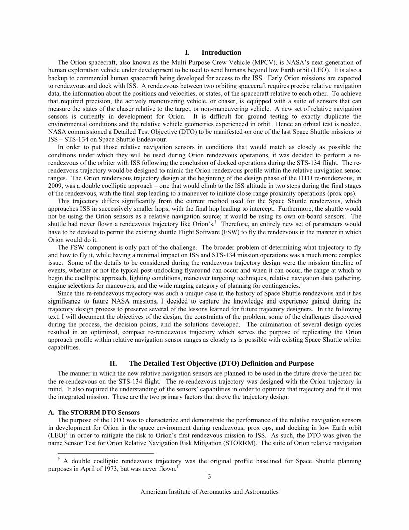
Figure 4. STORRM DTO Re-Rendezvous Relative Motion Trajectory with Example Scale.
-4000
-2000
0
2000
4000
6000
8000
10000
-400-30000-20000-1000001000020000
Z (
ft)
X (ft)
SEP1
SEP2NH2
NSR
SEP3
TPI
TDA
V‐Bar
R‐Bar
MC5
MC6
apogee is equal to the delta height between the two vehicles’ perigee, while both vehicles’ arguments of perigee are very nearly equal (see Fig. 3). Thus, the chaser’s orbit forms an ellipse entirely enclosed within the target’s orbit, and the relative motion plot forms a flat, horizontal line, representing an unchanging delta height between vehicles. Of course, because the chaser is in a lower orbit than the target, it will travel downrange slightly faster than the target. The “double” in double coelliptic refers to the fact that the chaser performs a maneuver to put itself in a coelliptic trajectory at two different altitudes during the approach. These maneuvers are NSR1 and NSR2 in Fig. 2. The figure represents the Orion reference trajectory relative motion design, as of July 2010, for a rendezvous with ISS.3,4
This type of trajectory was selected for Orion because some people believe that it provides superior navigation performance at large ranges using only relative angle measurements prior to the terminal phase. There is some disagreement with this assertion in the navigation field. However, the coelliptic approach does allow for a good angular variation in elevation angles to the target vehicle, which permits star tracker angle measurements to provide a good estimate of the relative state vector before the chaser reaches the maximum operational range of the VNS. In addition, it is possible to allow some maneuvers to be targeted for a specific elevation angle, thus providing a means of correcting for slight dispersions in the trajectory by adjusting the time of ignition (TIG) with little to no additional propellant cost. The TPI maneuver is targeted in this manner.
III. STORRM DTO Re-Rendezvous Trajectory Overview The STORRM DTO re-rendezvous trajectory was designed to replicate the second coelliptic portion of the Orion
rendezvous profile. In this region, the VNS would be at a close enough range to acquire the target vehicle and begin taking navigation measurements. A quick overview of the re-rendezvous trajectory is provided here, with a more detailed description to follow later.
Leading up to the re-rendezvous, the ISS/orbiter stack maneuvers to face the docking port forward, along the V-bar, for undocking. The orbiter then undocks and backs away from ISS along the +V-bar, until it reaches a predetermined distance ahead of ISS, where it can then perform a radial upward separation maneuver, called SEP1. An optional twice-orbital-rate flyaround of ISS could be performed prior to SEP1. Details regarding this will be discussed later. The SEP2 maneuver is then performed 28 minutes after SEP1 to complete the initial separation and begin the re-rendezvous. The re-rendezvous relative motion plot appears in Fig. 4. The turnaround distance is chosen so that the orbiter begins its coelliptic phase beyond the maximum VNS acquisition range. When the orbiter reaches the desired range, it performs a height adjustment maneuver, NH2‡, to lower its relative perigee to the desired coelliptic altitude. Once it reaches the coelliptic altitude, it performs the NSR maneuver to lower the relative apogee and achieve the coelliptic trajectory. The end of the coelliptic phase is defined by an elevation angle target for ISS relative to the orbiter. The TPI maneuver TIG is determined by the time at which this elevation angle occurs. This is the last burn of the re-rendezvous.
TPI takes the orbiter up to the Transition to Docking Axis (TDA) point. TDA is the point in the trajectory where the Orion spacecraft
‡ The maneuver is designated NH2 to differentiate it from the NH maneuver, which had a placeholder in the
original rendezvous with ISS on Flight Day 3 (FD3).

6
American Institute of Aeronautics and Astronautics
would maneuver to translate to the axis of the docking port to which it would dock. However, for the STORRM DTO re-rendezvous, this point is simply a reference point used for targeting the TPI burn and the trajectory was designed such that orbital mechanics would cause the orbiter to stall at TDA and then begin drifting down and away from ISS. After drifting past TDA, the orbiter performs the last separation maneuver, SEP3, to increase its opening rate and depart ISS for the last time. There are also two midcourse correction burns, MC5 and MC6 (also numbered to follow the original rendezvous burn sequence), to make minor trajectory adjustments to account for the latest relative navigation updates.
IV. Trajectory Design Constraints There are numerous factors that had to be taken into account during the conceptualization of the STORRM DTO
re-rendezvous trajectory design. The broad categories to consider included the mission timeline, STORRM sensor parameters and requirements, and orbiter and ISS vehicle operational constraints. These items had to be identified and addressed before the specific trajectory parameters could be designed.
A. Mission Timeline There were two major timeline activities to work around while designing the re-rendezvous – the post-undocking
flyaround of the orbiter around ISS and late inspections of the orbiter Thermal Protection System (TPS) tiles and Reinforced Carbon-Carbon (RCC) panels. Since the return to flight following the Columbia accident, there have been two TPS inspections using the Orbiter Boom Sensor System (OBSS) on each flight, one before docking on FD2 to check for ascent debris damage, and one following undocking to check for micro-meteoroid and orbital debris (MMOD) impacts during the mission. During the conceptual mission design phase, which is used to determine the feasibility of integrating the various payloads and activities of a mission, it was assumed that there would be a late inspection. The re-rendezvous would have to fit in the timeline without interfering with the inspection.
There were several options available, consisting of various combinations of flyaround, late inspection, and re-rendezvous occurring on the day of undocking or being spread out over two days. One possibility was to perform the late inspection during the outbound leg of the re-rendezvous and to complete the re-rendezvous on the next day. The main problem with this is that it would require stationkeeping beyond the range of the rendezvous radar, so the coelliptic portion of the trajectory would be more dispersed and the propellant cost would be higher than that of a same day re-rendezvous. Therefore, the plan was to focus on same day re-rendezvous cases.
The two primary options considered were to perform the late inspection immediately after the re-rendezvous on the day of undocking or to move the inspection to the next day. Neither option was desirable. Originally, the coelliptic portion of the re-rendezvous trajectory was designed exactly as it was in the final coelliptic of the Orion reference trajectory at that time. That made the coelliptic portion longer and resulted in a total time of about five hours. The same day option, when combined with the flyaround, would result in a very long crew work day. The next day option put the inspection on the day before landing, which interfered with deorbit preparation activities and gave the ground very little time to assess the inspection data to clear the orbiter for entry. Therefore, the re-rendezvous had to be made as short as possible to provide the capability to perform the inspection on the same day. This constraint factored into the selection of both the SEP2 maneuver targeting method and the NSR downrange position. The details will be described later, but these design decisions resulted in re-rendezvous duration from SEP1 to SEP3 of three and a half hours and a slightly lower propellant consumption.
Given that revision, the re-rendezvous duration was established by the determination that all three activities – the flyaround, the re-rendezvous, and the late inspection – could be squeezed into the same day. However, when it became clear that STS-134 would likely be one of the two last Space Shuttle missions to ISS, NASA decided to leave the OBSS at ISS. Therefore, the late inspection would have to be performed while the orbiter is docked, thus freeing up the timeline on the day of undocking. The new, shorter re-rendezvous plan was retained because of the propellant savings.
This lead to another set of options. The flyaround could now be done either immediately after undocking, as it normally is, or after the re-rendezvous. The purpose of the flyaround is to obtain photographic documentation of ISS following completion of the docked portion of the mission. The consideration of performing the flyaround after the re-rendezvous is related to propellant budgeting and mission priorities. Each mission has a list of activity priorities, which is used both during mission planning to make decisions regarding activity scheduling and during mission operations in case anomalies occur and there are not enough resources for the completion of all remaining activities. On STS-134, the STORRM DTO re-rendezvous is a higher priority than the flyaround. However, if the

7
American Institute of Aeronautics and Astronautics
Figure 5. NSR Position Design Parameters.
Z-a
xis
X-axis
NSRTPI
TDA
V‐Bar
R‐Bar
MC6
X dot = 7.88 fps
Z = 4600 ft
X = ‐5088 ft X = ‐21163 ft
flyaround uses significantly more propellant than predicted and there is not enough to complete the re-rendezvous, the re-rendezvous would have to be called off.
The possibility of performing the flyaround after the re-rendezvous was briefly considered. This option was quickly dismissed for two main reasons. One was that there would be a significant dispersion on the orbiter state relative to ISS at TDA. If the flyaround were to begin from that point, there would be a significant amount of analysis required to determine all the possible actions to take to establish a good starting state for the flyaround. The other reason was that the lighting would not be ideal for the flyaround. The flyaround is for photography of ISS, which requires daylight. The TPI is designed to occur at noon + 14 minutes for the STORRM VNS. The additional 26 minutes from TPI to TDA would put the beginning of the flyaround near sunset. So, it was decided that the flyaround would be performed first. The propellant budgeting issue would be handled by assessing the amount of propellant available for both the flyaround and the re-rendezvous and, if there would not be enough to cover both, the flyaround would be called off and the undocking would transition directly to the re-rendezvous.
B. STORRM Sensor Parameters / Requirements The STORRM experiment requirements on the re-rendezvous trajectory resulted primarily from the VNS
predicted capabilities and limitations. The main considerations were operating ranges and field-of-view restrictions. 1. Range at NSR As stated earlier, the STORRM
DTO required the orbiter to be closing with ISS in the coelliptic portion of the re-rendezvous prior to reaching the VNS acquisition range, predicted to be about 3 nm. This established a minimum downrange distance limit on the NSR maneuver. But what should the design downrange distance be? The answer to this question required an iterative approach to the solution. It was established early on that the orbiter should be on the coelliptic trajectory before reaching 6 km (19685 ft or ~3.2 nm), to allow for some time to re-establish a target track attitude after the NSR maneuver and guarantee proper VNS pointing for a clean acquisition of ISS. But the design position would have to account for trajectory dispersions, so that if the orbiter arrived at NSR closer to ISS than predicted, it would still be beyond 6 km.
Two factors involving the selection of the NSR position were established by the Orion trajectory design3,4 : the TPI X position was negative 5088 ft and the delta height of the coelliptic trajectory was 4600 ft. By default, the NSR Z position must be the desired coelliptic delta height. That delta height determines the closing rate of the trajectory explicitly, due to orbital mechanics. At the ISS altitude, for a ∆H of 4600 ft, the X-axis translational rate (X-dot, or ) is 7.88 fps. These key values are depicted in Fig. 5. Thus, when choosing the NSR position, the transfer time between NSR and TPI is also being chosen.
I needed to make an initial guess as to what the NSR X position should be. Since my trajectory design tool used nautical miles for downrange targeting units, I arbitrarily selected -3.5 nm (-21266 ft) to get started. By the following math,
(1)
which accounts for the transfer distance to the TPI X position, the 3.5 nm NSR range results in a 34.2-minute transfer from NSR to TPI.
8
American Institute of Aeronautics and Astronautics
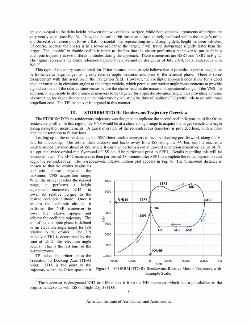
Figure 6. STORRM DTO Priority Zones.
Z-a
xis
X-axis
Rerndz
Rerndz Mnvrpnts
Required
Highly Desired
Desired
SEP1
SEP2
NSR
SEP3
TPI
TDA
V‐Bar
R‐Bar
MC6
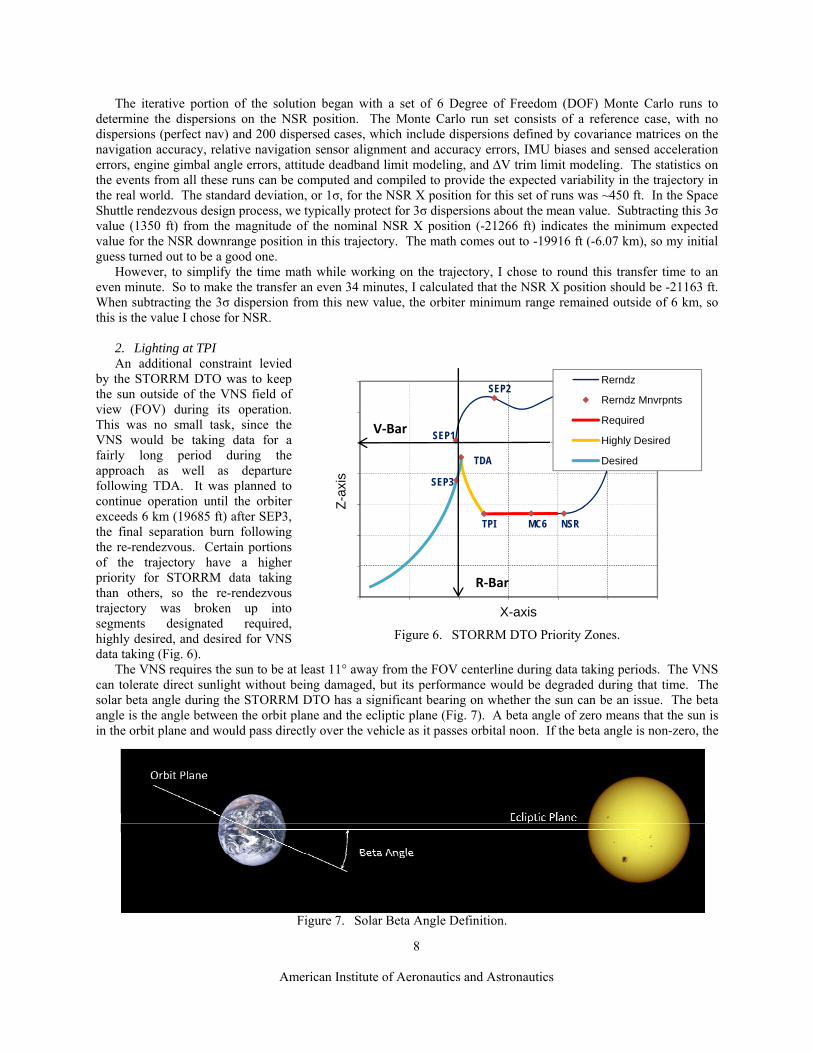
Figure 7. Solar Beta Angle Definition.
The iterative portion of the solution began with a set of 6 Degree of Freedom (DOF) Monte Carlo runs to determine the dispersions on the NSR position. The Monte Carlo run set consists of a reference case, with no dispersions (perfect nav) and 200 dispersed cases, which include dispersions defined by covariance matrices on the navigation accuracy, relative navigation sensor alignment and accuracy errors, IMU biases and sensed acceleration errors, engine gimbal angle errors, attitude deadband limit modeling, and ∆V trim limit modeling. The statistics on the events from all these runs can be computed and compiled to provide the expected variability in the trajectory in the real world. The standard deviation, or 1σ, for the NSR X position for this set of runs was ~450 ft. In the Space Shuttle rendezvous design process, we typically protect for 3σ dispersions about the mean value. Subtracting this 3σ value (1350 ft) from the magnitude of the nominal NSR X position (-21266 ft) indicates the minimum expected value for the NSR downrange position in this trajectory. The math comes out to -19916 ft (-6.07 km), so my initial guess turned out to be a good one.
However, to simplify the time math while working on the trajectory, I chose to round this transfer time to an even minute. So to make the transfer an even 34 minutes, I calculated that the NSR X position should be -21163 ft. When subtracting the 3σ dispersion from this new value, the orbiter minimum range remained outside of 6 km, so this is the value I chose for NSR.
2. Lighting at TPI An additional constraint levied
by the STORRM DTO was to keep the sun outside of the VNS field of view (FOV) during its operation. This was no small task, since the VNS would be taking data for a fairly long period during the approach as well as departure following TDA. It was planned to continue operation until the orbiter exceeds 6 km (19685 ft) after SEP3, the final separation burn following the re-rendezvous. Certain portions of the trajectory have a higher priority for STORRM data taking than others, so the re-rendezvous trajectory was broken up into segments designated required, highly desired, and desired for VNS data taking (Fig. 6).
The VNS requires the sun to be at least 11° away from the FOV centerline during data taking periods. The VNS can tolerate direct sunlight without being damaged, but its performance would be degraded during that time. The solar beta angle during the STORRM DTO has a significant bearing on whether the sun can be an issue. The beta angle is the angle between the orbit plane and the ecliptic plane (Fig. 7). A beta angle of zero means that the sun is in the orbit plane and would pass directly over the vehicle as it passes orbital noon. If the beta angle is non-zero, the
9
American Institute of Aeronautics and Astronautics
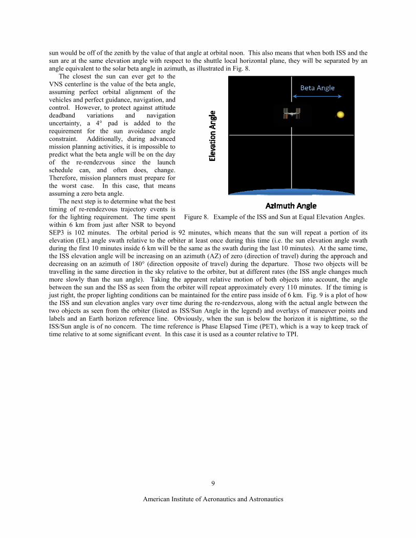
Figure 8. Example of the ISS and Sun at Equal Elevation Angles.
sun would be off of the zenith by the value of that angle at orbital noon. This also means that when both ISS and the sun are at the same elevation angle with respect to the shuttle local horizontal plane, they will be separated by an angle equivalent to the solar beta angle in azimuth, as illustrated in Fig. 8.
The closest the sun can ever get to the VNS centerline is the value of the beta angle, assuming perfect orbital alignment of the vehicles and perfect guidance, navigation, and control. However, to protect against attitude deadband variations and navigation uncertainty, a 4° pad is added to the requirement for the sun avoidance angle constraint. Additionally, during advanced mission planning activities, it is impossible to predict what the beta angle will be on the day of the re-rendezvous since the launch schedule can, and often does, change. Therefore, mission planners must prepare for the worst case. In this case, that means assuming a zero beta angle.
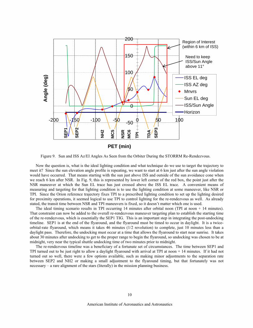
The next step is to determine what the best timing of re-rendezvous trajectory events is for the lighting requirement. The time spent within 6 km from just after NSR to beyond SEP3 is 102 minutes. The orbital period is 92 minutes, which means that the sun will repeat a portion of its elevation (EL) angle swath relative to the orbiter at least once during this time (i.e. the sun elevation angle swath during the first 10 minutes inside 6 km will be the same as the swath during the last 10 minutes). At the same time, the ISS elevation angle will be increasing on an azimuth (AZ) of zero (direction of travel) during the approach and decreasing on an azimuth of 180° (direction opposite of travel) during the departure. Those two objects will be travelling in the same direction in the sky relative to the orbiter, but at different rates (the ISS angle changes much more slowly than the sun angle). Taking the apparent relative motion of both objects into account, the angle between the sun and the ISS as seen from the orbiter will repeat approximately every 110 minutes. If the timing is just right, the proper lighting conditions can be maintained for the entire pass inside of 6 km. Fig. 9 is a plot of how the ISS and sun elevation angles vary over time during the re-rendezvous, along with the actual angle between the two objects as seen from the orbiter (listed as ISS/Sun Angle in the legend) and overlays of maneuver points and labels and an Earth horizon reference line. Obviously, when the sun is below the horizon it is nighttime, so the ISS/Sun angle is of no concern. The time reference is Phase Elapsed Time (PET), which is a way to keep track of time relative to at some significant event. In this case it is used as a counter relative to TPI.
10
American Institute of Aeronautics and Astronautics
Figure 9. Sun and ISS Az/El Angles As Seen from the Orbiter During the STORRM Re-Rendezvous.
-100
-50
0
50
100
150
200
-200 -150 -100 -50 0 50 100
Ang
le (d
eg)
PET (min)
ISS EL deg
ISS AZ deg
Mnvrs
Sun EL deg
ISS/Sun Angle
Horizon
TPI
TDA
SEP3
NSR
MC
6
MC
5
NH
2
SEP2
SEP1
Region of Interest(within 6 km of ISS)
Need to keepISS/Sun Angleabove 11°
Now the question is, what is the ideal lighting condition and what technique do we use to target the trajectory to meet it? Since the sun elevation angle profile is repeating, we want to start at 6 km just after the sun angle violation would have occurred. That means starting with the sun just above ISS and outside of the sun avoidance cone when we reach 6 km after NSR. In Fig. 9, this is represented by lower left corner of the red box, the point just after the NSR maneuver at which the Sun EL trace has just crossed above the ISS EL trace. A convenient means of measuring and targeting for that lighting condition is to use the lighting condition at some maneuver, like NSR or TPI. Since the Orion reference trajectory fixes TPI to a prescribed lighting condition to set up the lighting desired for proximity operations, it seemed logical to use TPI to control lighting for the re-rendezvous as well. As already stated, the transit time between NSR and TPI maneuvers is fixed, so it doesn’t matter which one is used.
The ideal timing scenario results in TPI occurring 14 minutes after orbital noon (TPI at noon + 14 minutes). That constraint can now be added to the overall re-rendezvous maneuver targeting plan to establish the starting time of the re-rendezvous, which is essentially the SEP1 TIG. This is an important step in integrating the post-undocking timeline. SEP1 is at the end of the flyaround, and the flyaround must be timed to occur in daylight. It is a twice-orbital-rate flyaround, which means it takes 46 minutes (1/2 revolution) to complete, just 10 minutes less than a daylight pass. Therefore, the undocking must occur at a time that allows the flyaround to start near sunrise. It takes about 30 minutes after undocking to get to the proper range to begin the flyaround, so undocking was chosen to be at midnight, very near the typical shuttle undocking time of two minutes prior to midnight.
The re-rendezvous timeline was a beneficiary of a fortunate set of circumstances. The time between SEP1 and TPI turned out to be just right to allow a daylight flyaround with arrival at TPI at noon + 14 minutes. If it had not turned out so well, there were a few options available, such as making minor adjustments to the separation rate between SEP2 and NH2 or making a small adjustment to the flyaround timing, but that fortunately was not necessary – a rare alignment of the stars (literally) in the mission planning business.

11
American Institute of Aeronautics and Astronautics
C. Orbiter and ISS Operational Constraints The Space Shuttle orbiter capabilities also played a large part in the design of the re-rendezvous trajectory. The
orbiter would have to be able to fly this new trajectory without the benefit of any updates to its hardware or flight software, both of which are expected to be significantly different for any new vehicle design. One of the reasons for developing the Orion reference trajectory in the first place was to aid in the design of the vehicle itself.
1. Navigation When operating at short ranges from another vehicle, as is the case here, the orbiter typically relies upon the Ku-
band antenna as a radar transceiver, known as rendezvous radar, as its best source for relative range and range rate information. The rendezvous radar’s maximum operational range is 135,000 ft. With the re-rendezvous trajectory nominally extending to a maximum of about 31,000 ft, the orbiter would be within radar range for the entire time. Therefore, nominally over the majority of the trajectory, the orbiter’s relative state knowledge should be excellent.
However, when the range is very small (on the order of a few thousand feet), the radar data becomes a bit erratic. Because of the significant size of ISS and the fact that it does not possess a transponder to provide a consistent, precise point target, the radar tends to wander over the structure of ISS. At these smaller ranges, ISS is no longer effectively a point source and the subtended angle covered by the ISS structure is large enough to create jumps in the radar measurements as the antenna picks up signals reflected from varying sections of the vehicle. At this point, we need to switch to a navigation sensor that can discriminate which section of ISS it will consistently use as a reference point.
There are two sensors on board that can be used inside of 5000 ft, the Trajectory Control Sensor (TCS) and the Hand Held Light Detection and Ranging (LIDAR) (HHL). However, neither of these sensors sends data to the on-board targeting software. They are only used for crew and Mission Control Center (MCC) situational awareness during prox ops, when the crew is manually piloting the vehicle. The TCS is a laser system mounted in the payload bay of the orbiter and requires retro-reflectors on the ISS5. The data from TCS feeds into a laptop computer using the Rendezvous and Proximity Operations Program (RPOP)1 which filters the data and displays relative position, range, and range rate information. The HHL is available as a backup to TCS, but is also used in parallel with TCS to provide confirmation of the integrity of the TCS data. The HHL is manually pointed out the overhead window by a crew member at a pre-designated structural element of ISS to get consistent range and range rate data.
2. ISS Factors None of the maneuvers are targeted using TCS or HHL data. These sensors are only used for situational
awareness. However, data from one of these sensors is required during the coast period following TPI to ensure that the orbiter will not close to inside of 600 ft from ISS. The ISS has constraints on how close the orbiter can get to it due to reaction control system (RCS) plume impingement structural loads. During prox ops and docking, ISS feathers its solar arrays so that they are edge-on to the RCS thruster plume from the orbiter as it makes its fine trajectory adjustments during approach. Without these precautions, the force of the expanding thruster exhaust could bend or break the array support structure. During the re-rendezvous, since the orbiter is not planning to make a final approach for docking, the ISS will keep its solar arrays in an operational alignment so that they can continue producing power.
Braking gates at 2000 ft, 1500 ft, and 1000 ft exist to guarantee a sufficient minimum range at TDA. If the pre-designated range rate is exceeded at any of these ranges, the crew would command braking pulses from the RCS jets to reduce the rate to the limit for that gate. If the rate has not stalled by a range of 600 ft, the crew would null the rate at that time. There is also a set of contingency braking gates, which employ slightly lower rate limits at each gate and move the final null-rate gate from 600 ft to 1000 ft. These contingency braking gates would have been used if any backup systems, such as alternate RCS jets or relative navigation sensors, were being used to complete the re-rendezvous.
It was also desirable to limit the amount of time ISS spends out of its normal operating attitude. When the orbiter is not in close proximity to ISS, it usually maintains a torque equilibrium attitude (TEA). This is a gravity gradient stabilized attitude, which limits the amount of attitude control inputs required to keep ISS stable. During the STORRM DTO re-rendezvous approach, ISS was required to maintain an attitude that allowed the VNS to have a clear line of sight to a TCS reflector mounted on ISS. The planned ISS attitude was a docking TEA (DTEA) attitude, the expected nominal attitude when ISS construction has been completed and an Orion spacecraft is docking. This attitude is close to the docking attitude for the orbiter, but pitched down slightly, which would provide the necessary view of TCS reflectors and would represent the attitude expected during an operational Orion
12
American Institute of Aeronautics and Astronautics
rendezvous flight. The time in this attitude was limited to approximately 120 minutes2, roughly the time the orbiter would be within 6 km.
3. Orbiter Control During the re-rendezvous, the orbiter was required to control its trajectory while maintaining a target tracking
attitude simultaneously. The target track attitude was not only required for STORRM during data taking periods, but was also required for relative navigation data from radar. The orbiter has three different engine selection options for translational maneuvers – RCS multi-axis, +X RCS, or the Orbital Maneuvering System (OMS). Engine selection and orbiter attitude requirements during translational maneuvers are dictated by the size of the maneuver. Large burns require both OMS engines. Some smaller burns like the Ti burn for the typical orbiter rendezvous trajectory use a single OMS engine. The OMS engines are the nozzles protruding from the pods next to the vertical stabilizer. Since these only can point backward, out the –X-axis, the orbiter must maneuver to an attitude that points the nose (+X-axis) toward the direction of the desired ∆V. The same is true for the +X RCS jets, which are also located behind the OMS pods and pointing backward. But for the smallest burns (typically less than 4 fps), the RCS multi-axis mode is used. This mode requires the crew to command thrusting one axis at a time using the translational hand controller (THC). The digital auto-pilot (DAP) commands the appropriate set of RCS jets, located all around the vehicle, to fire to give the appropriate thrust direction. All of the re-rendezvous translational maneuvers are less than 4 fps, so that allows the orbiter to stay in the target track attitude at all times.
There are also three options available for attitude control – Vernier RCS (VRCS), Primary RCS (PRCS), or alternate DAP (ALT DAP). The VRCS is composed of six small jets, four aft and two forward. It is designed to provide very fine attitude control and is the most propellant-efficient method for attitude control. But since there are only six of these jets, there is a significant amount of cross-coupling, meaning jet firings to control rotation about one axis also effect one or both of the other axes. There are no VRCS jets that fire upward, in the –Z axis direction. As a result, over long durations in nearly the same attitude, there tends to be a net ∆V in the direction the payload bay is pointed, producing a bias in the trajectory. The target track attitude keeps the –Z axis pointed generally in the direction of travel for the entire re-rendezvous, so the orbiter would get a net energy growth in the orbit from the VRCS.
The PRCS is composed of 38 larger jets, clustered in groups of two to four all around the orbiter for redundancy. There is still some cross-coupling with PRCS firings, but not as much as with the VRCS. ALT DAP is an alternate form of PRCS attitude control initially developed to reduce loading on payloads attached to the Remote Manipulator System (RMS). But it is also used to reduce propellant consumption by limiting the maximum number of jets firing simultaneously.6
The dispersions in position at TDA were the most critical concern for the re-rendezvous trajectory. The orbiter would be coasting from TPI for 26 minutes toward a point only about 1000 ft from ISS. There will be more details about the dispersions at TDA later, but a preliminary look at attitude control influences on dispersions was required early in the design process. The Monte Carlo analysis showed that of the three attitude control options, the VRCS trajectory was the least dispersed at TDA. The relatively frequent translational maneuvers along the trajectory sufficiently compensate for the energy growth tendency and the small thrusters do not impart significant undesired translations. The PRCS mode produces TDA position dispersions about 20% higher than VRCS, but the propellant cost is about 50% higher. ALT DAP attitude control propellant use is somewhere between VRCS and PRCS, but the dispersions at TDA are the highest of the three modes. Both PRCS and ALT DAP are acceptable as a backup mode; but, it is a pretty clear cut choice to use VRCS for attitude control nominally during the re-rendezvous because it provides the smallest trajectory dispersions and lowest propellant consumption.
V. Details of the Re-Rendezvous Trajectory Design In the preceding sections, there has been a significant amount of discussion about a number of design details
regarding requirements and constraints imposed on the trajectory. But there were also a great number of design choices to be made that are not directly dependent upon any constraints. Instead, these choices factor things like propellant efficiency, controllability, safety, and contingencies into the design selection. In this section, the complete details of the design of the re-rendezvous maneuvers are discussed, including the purpose, timing, targeting, and execution of each burn.
The re-rendezvous is initiated with undocking. The timing of undocking dictates some of the actions required during the re-rendezvous, since the VNS has the sun angle constraint, mentioned previously, and the timing of TPI is required to fall within a narrow window of time relative to orbital noon. Therefore, undocking is targeted for orbital

13
American Institute of Aeronautics and Astronautics
Figure 10. Post-Undocking Trajectories with and without a Flyaround.
midnight, which sets up the proper lighting for the flyaround photography and works well for VNS lighting during the coelliptic approach. As mentioned previously, if there was not sufficient propellant to perform both the flyaround and the re-rendezvous, the flyaround would be deleted. Therefore, there needed to be a plan in place for a no-flyaround scenario. In either case, the orbiter separates to a distance of 450 ft ± 50 ft ahead of ISS. At this distance, the flyaround is initiated or, if the flyaround is to be waived, SEP1 is executed, as illustrated in Fig. 10. The flyaround completes its lap around ISS in half a revolution (rev), a duration of 46 minutes, and returns to the +V-bar at a distance of 650 ft ± 50 ft. Without arresting its motion from the flyaround, the orbiter then performs the SEP1 burn.
A. SEP1 and SEP2 Maneuvers There are two disparities between the flyaround and no-flyaround scenarios to be addressed. First is the change
in timing of the SEP1 maneuver. The nominal re-rendezvous assumes that a flyaround is performed and the timing of all re-rendezvous events are optimized for this case. If the flyaround does not occur, SEP1 becomes 46 minutes early. There is a solution for that problem, but to understand it will require the understanding of some of the details of the trajectory design yet to be discussed, so this topic will be revisited later.
The second issue is the SEP1 ∆V. For procedural simplicity, SEP1 is always performed as a radial up ∆V of 1.5 fps. This puts the orbiter on a trajectory up and over the top of ISS, as illustrated in Figs. 10 and 11. This motion puts the orbiter in the proper position to perform SEP2 28 minutes later. But since the motion of the orbiter is not halted following completion of the flyaround, there is a residual ∆V leftover from the motion around ISS. This motion is a by-product of the manual piloting inputs required to maintain a constant range between the two vehicles during the flyaround. This residual ∆V nominally just happens to be about 1.5 fps radial up. But, things don’t always work out to be nominal, and dispersions during the flyaround can cause that ∆V to vary significantly, so to guarantee a safe separation trajectory, the SEP1 of 1.5 fps is still performed. So, there could be a roughly 1.5 fps difference between the flyaround and no-flyaround scenarios. That turns out to be no problem. Since the ∆V is in the radial direction, it does not contribute to the energy of the orbit; it only impacts the orbiter position at the SEP2

14
American Institute of Aeronautics and Astronautics
Figure 11. Post-SEP1 Trajectories with and without a Flyaround. (motion assumes SEP2 ∆V = 0)
-4000
-3000
-2000
-1000
0
1000
2000
3000
-14000-12000-10000-8000-6000-4000-200002000
Z (
ft)
X (ft)
Flyaround
Flyaround Mnvrpnts
No Flyaround
No Flyaround Mnvrpnts
SEP1
Flyaround SEP2
No Flyaround SEP2
V‐Bar
R‐Bar
burn. And, as will be described next, the method used for targeting the SEP2 burn can compensate for that difference.
The purpose of SEP2 is to establish a safe opening rate. Fig. 11 shows the relative motion if SEP2 is not executed. The orbiter loops back toward ISS because SEP1 is mostly radial. The loop would be a closed circle returning to the SEP1 location for a purely radial ∆V, however, there is a small posigrade component in SEP1 due to the cant of the +X RCS engines. Regardless, the resulting motion is not considered safe, because the orbiter returns to within half the distance of its maximum range following SEP1.
The SEP2 maneuver is targeted as a phasing maneuver. That’s rendezvous design language meaning that it is sized to result in some specific downrange distance from the target vehicle at some particular time after the maneuver. In particular, SEP2 is targeted to achieve the desired X position of NSR in slightly more than one rev. The exact timing is computed to set up the desired time of TPI relative to noon. The time between most of the re-rendezvous maneuvers is fixed. Only the time between SEP2 and NSR can be adjusted to tweak the arrival time at TPI, so this is how a balance between TPI time (for the STORRM DTO) and undocking time (for flyaround photography) is achieved.
This flexibility also allows for some variability in SEP1 position, timing, and ∆V. SEP2 can compensate for the difference between the effective ∆Vs of the flyaround and no-flyaround scenarios. Assuming there are no large timing issues (which in reality, there is that half rev discrepancy noted earlier, but that will be discussed later), the no-flyaround SEP2 ∆V would have to be slightly larger than that of the flyaround SEP2, since the no-flyaround SEP2 position is slightly lower and closer to ISS. It would therefore require more energy input to get the orbiter to travel the slightly longer distance to the fixed relative position desired for NSR in the same amount of time. The difference in possible SEP1 positions is rather small (200 to 300 ft along the V-bar) and only results in about 0.1 fps difference in SEP2 ∆V. This illustrates the robust nature of the SEP2 design. The SEP2 burn can easily compensate for the inevitable dispersions in the SEP1 relative position and velocity, which would certainly be less than the difference between the flyaround and no-flyaround conditions.
At SEP1, the orbiter attitude is nose up with the payload bay facing (-Z axis pointing toward) ISS. After SEP1, it is pitching up in the process of maneuvering to a payload bay to Earth attitude (see Fig. 10). Before that maneuver is completed, the orbiter is to be commanded to go to a target track attitude, which points the –Z axis toward ISS and maintains that pointing as the relative positions of the two vehicles change over time. This attitude would be maintained throughout the entire re-rendezvous, even during burns, since every maneuver is small enough to be performed using the multi-axis engine selection, as stated previously. This would allow the VNS to maintain visibility of ISS when it is taking data as well as allow the rendezvous radar to maintain lock and provide relative navigation data to the on-board FSW to be used for targeting maneuvers. Radar data is the nominal relative navigation data source for all of the re-rendezvous maneuvers.
B. Altitude Adjustment (NH2) Maneuver The next maneuver in the sequence is NH2. It is planned to occur roughly about 0.7 revs after SEP2 and about
half a rev before NSR. The purpose of the burn is to establish the proper coelliptic ∆H at the time of the NSR burn. The NH2 is targeted purely as a height adjustment maneuver – it does not attempt to control the downrange position of NSR. In a sense, SEP2 and NH2 work as a cooperative pair of maneuvers in the rendezvous targeting algorithm. SEP2 controls the X position at NSR and NH2 controls the Z position.

15
American Institute of Aeronautics and Astronautics
Figure 12. 3σ Dispersions with and without Midcourse Maneuvers.
Z-a
xis
X-axis
Rerndz
Rerndz Mnvrpnts
Nom 3-sigma Dispersions
No MCs 3-sigma Dispersions
NSRTPI
TDA
V‐Bar
R‐Bar
MC6
SEP2 and NH2 targeting is done on the ground because the FSW does not have the logic to perform simultaneous multi-maneuver rendezvous targeting. However, the navigation data comes from the orbiter’s rendezvous radar because that is the best navigation data source at the ranges experienced during the re-rendezvous. The relative navigation data is downlinked real time and the flight controllers on the ground target the rendezvous maneuvers using an integrated maneuver targeting software tool named the Orbital Maneuver Processor (OMP). OMP has a heritage dating back to the Gemini program1 and an evolved version is used for pre-flight and real time rendezvous maneuver planning on all Space Shuttle flights. The ground-targeted maneuver TIG and ∆V are then uplinked to the orbiter for execution by the crew on-board.
The time of the NH2 is established by the separation rate produced by SEP2. Essentially, when the orbiter X position equals the NSR X position, the NH2 must be performed to drop down to the coelliptic altitude. However, since the separation trajectory is not purely coelliptic (there is some waviness in the relative motion), there is some deviation from this rule to produce the most propellant efficient trajectory. The most efficient trajectory is established by tweaking the NH2 TIG to null the Z-component of the NSR ∆V. That signifies that just the right amount of energy change is being made at just the right time to smoothly transition to exactly the desired coelliptic ∆H.
C. Midcourse Correction 5 (MC5) Maneuver Of course, dispersions are inevitable, especially considering the fact that SEP2, which targeted the NSR X
position occurred about an hour earlier. The MC5 midcourse burn was added to significantly reduce dispersions on the NSR position (as can be seen by comparing the large blue, no-MC5 ellipse and small yellow, with-MC5 ellipse around NSR in Fig 12). MC5 is a Lambert-targeted burn, meaning it is designed to hit a specific point in space relative to the target, namely the NSR position, after a specific transit time. The timing of MC5 was chosen to be 25 minutes prior to NSR, which is a little less than half way from NH2 to NSR. Typically, midcourse correction maneuvers are more efficient the earlier they occur. A smaller ∆V propagated over a longer transit time or trajectory arc can achieve the same effect as a larger ∆V over a short arc. The MC5 TIG was chosen as a good compromise between the desire to optimize ∆V and the need to take radar navigation updates after the NH2.
All re-rendezvous maneuvers subsequent to NH2 are computed via crew-initiated, Lambert targeting by the on-board FSW. The FSW has an iterative Lambert targeting algorithm that is used for the nominal rendezvous on all flights. The only limitations are that it must target for a transfer time less than one rev (no multi-rev Lambert targeting capability exists) and it is desirable to avoid a 180° transfer arc between the maneuver and targeted positions. A solution singularity exists here due to the fact that there are an infinite number of out-of-plane solutions resulting from the common node set up by a maneuver. Any number of out-of-plane ∆V components will reach the target position in any half-rev increment since two orbital planes intersect at opposite sides of an orbit. The FSW will only provide downtrack and altitude control in this singularity region. However, we typically avoid targeting Lambert burns for transfer angles ranging from about 160° to 200° to so that the solution includes control in all three axes.
D. Coelliptic (NSR) Maneuver The NSR maneuver’s purpose is to establish the coelliptic portion of the trajectory at the desired ∆H. The NSR
was originally planned to be ground targeted, since the orbiter’s FSW does not have the capability to target a
16
American Institute of Aeronautics and Astronautics
coelliptic maneuver. However, it was later changed to a Lambert burn targeting the TPI position. This works because the TPI maneuver lies on the coelliptic trajectory at the desired ∆H and the transfer time from NSR to TPI is not a full or half revolution. The Lambert targeting solution results in a trajectory that is essentially coelliptic. The short transit time (34 minutes) is the key to making this targeting method successful. It restricts the relative trajectory to a straight line.
The trajectory team arrived at this solution by way of limitations imposed by the Shuttle Avionics Integration Lab (SAIL) simulator capabilities. The FSW inputs for the re-rendezvous maneuver targets had to be tested in the SAIL, a simulator with complete, full-scale orbiter avionics wiring and electronics, used to verify the FSW performance in an integrated environment. There was no easy way to insert a ground targeted maneuver into the full re-rendezvous simulation without interrupting the run and re-initializing it. The FSW requirements co-owners substituted Lambert targeting for NSR and found it looked very similar to the simulation output data sent to them by flight design for a ground targeted NSR. After reviewing the SAIL results and independently analyzing the robustness of the Lambert targeting method, we decided to use it. Targeting NSR as a Lambert burn simplified the operational procedure and helped to relieve the flight controllers’ real time work load during this portion of the trajectory, since there was no longer a need to uplink a maneuver solution during a very time-constrained period.
E. Midcourse Correction 6 (MC6) Maneuver The next maneuver is MC6. Like MC5, this midcourse correction maneuver is timed to occur slightly earlier
than half way between two maneuvers, for the same reasons as described for MC5. MC6 is 14 minutes after NSR and 20 minutes before TPI. It is intended to reduce dispersions on both the TPI position and time of arrival.
F. Terminal Phase Initiation (TPI) Maneuver The TPI maneuver TIG is allowed to float relative to MC6 based on the elevation angle of ISS relative to the
orbiter as determined by the relative navigation data. Until MC6 is executed, the TPI TIG is planned to occur at a fixed time of fourteen minutes after noon. After MC6, an elevation angle of 42° is used to establish the TIG. This angle was derived using data from Orion rendezvous techniques3,4. Orion will execute TPI when it crosses an imaginary ideal reference trajectory that would allow it to coast in to a specific state at TDA. Orion’s FSW will actively command jet firings to maintain that trajectory within certain tolerances until it reaches TDA. The shuttle orbiter does not have this FSW logic. To approximate this logic, we use capabilities that exist in the orbiter’s targeting FSW.
The position representing the intersection of the 4600 ft ∆H and the ideal reference trajectory establishes the X position, which is used to compute the elevation angle. This 42° fixed elevation angle is loaded into the FSW target set pre-flight. The on-board Lambert targeting routine uses a combination of elevation angle, transfer time, and desired relative position to compute the TIG and determine the ∆V, when performed at that TIG, to achieve a 26 minute coasting trajectory that reaches the TDA position with near-zero relative velocity.
G. Transition to Docking Axis (TDA) Point and SEP3 Maneuver There are no planned maneuvers after TPI until SEP3. The trajectory has been designed to stall at TDA, 26
minutes after TPI at X = -333 ft and Z = 1000 ft. However, as has already been discussed, there are braking gates within 2000 ft of ISS to ensure that the orbiter does not close to a range of less than 600 ft.
The SEP3 maneuver has been added to increase the separation rate to ensure safe long-term motion relative to ISS. It is a simple 1 fps retrograde burn executed 15 minutes after TDA. The orbiter remains in a target track attitude until its range exceeds 6 km. At that point, the STORRM DTO would discontinue data taking and the crew would move on to other tasks in the timeline.
H. Summary of Dispersion Results The 3σ dispersion ellipses for each maneuver are plotted in Fig. 13. It is clearly evident that the post-MC5
dispersions are much smaller than those of the early maneuvers, which indicates that the targeting methods are working as desired to bring the trajectory under control for the approach. The large dispersions at SEP2 and NH2 result from dispersions on the pre-SEP1 states due to the flyaround – primarily from the relative velocity variability. There is no control on NH2 position; SEP2 is controlling the NSR X position. In fact, SEP2, NH2, and MC5 all exist for the sole purpose of controlling the state at NSR. The marked improvement in dispersions at NSR is the result. That sets the stage for a well behaved coelliptic approach, requiring only a small tweak by MC6 to maintain a relatively unperturbed TPI arrival time and position.

17
American Institute of Aeronautics and Astronautics
Figure 13. Re-Rendezvous Trajectory with 3σ Dispersions.
Z-a
xis
X-axis
SEP1
SEP2NH2
NSRTPI
TDA
V‐Bar
R‐Bar
MC5
MC6
I. Out-of-Plane Maneuver Components There are a few more details concerning the overall re-rendezvous trajectory design to be discussed. The first is
planar control. The orbiter would be in an orbit plane that would deviate very little from the ISS plane. Some variance can be expected due to attitude control and maneuvers, but it is unlikely that it would accumulate significantly over three and a half hours. It is likely that the largest contributor to any Y-component in maneuver targeting solutions would be relative navigation errors. For that reason, the trajectory team decided that the Y-component of burn solutions would not be executed unless there is compelling evidence that it is required. Such evidence would be a crew visual verification that the ISS position in the centerline camera does not correctly correspond to the orbiter’s LVLH attitude readout.
J. Maneuver Trim Limits The second general rule applies to maneuver trim limits. Trim limits define the fidelity to which the crew burns the ∆V components of a multi-axis RCS maneuver. The FSW transforms the maneuver LVLH ∆V solution to body coordinates. The ∆V components in body coordinates are displayed as velocities-to-go (VGOs). They are “fly-to” instructions that serve as a guide to the crew while executing the burn and are decremented on the display while the crew is commanding RCS firings. The DAP setting for THC pulses is 0.1 fps per pulse. That means that when the DAP is set to pulse mode, each time an electrical contact is made by the crew deflecting the THC, the proper RCS jets fire for the necessary duration to create a 0.1 fps ∆V in that direction. Typically, the trim limits on rendezvous burns are 0.2 fps. This limit was established to prevent the crew from “chasing the VGOs” during Lambert targeted burns, where the FSW continually retargets the maneuver solution as the burn progresses to account for the accelerations sensed by the Inertial Measurement Units (IMUs). This “Lambert Guidance” routine had been somewhat erratic in the past, but it has been updated with a more stable routine in the current version of the FSW. The nominal rendezvous procedures were never updated since there was no pressing need to do so; 0.2 fps trim limits provide sufficient accuracy for a Stable Orbit Rendezvous (SOR). However, Monte Carlo analysis has shown that the coelliptic trajectory is a bit more sensitive to trajectory disturbances than the SOR trajectory. The 0.1 fps trim limit contributes to an improvement in overall trajectory dispersions as well as the total propellant consumption of the re-rendezvous.

18
American Institute of Aeronautics and Astronautics
Figure 14. Example Coelliptic Intersection with Elevation Angle.
0
1000
2000
3000
4000
5000
6000
-25000-20000-15000-10000-50000
Z (
ft)
X (ft)
Nominal Rerndz
Nominal Mnvrpnts
4200 ft Delta-H
5000 ft Delta-H
42 deg El Ang
NSRTPI
TDA
V‐Bar
R‐Bar
MC6X dot = 7.88 fpsZ = 4600 ft
X = ‐5088 ft X = ‐21163 ft
X dot = 7.16 fps
X dot = 8.54 fps
VI. Trajectory Design Challenges A limited experience base working with the coelliptic approach trajectory introduced a few challenges to the re-
rendezvous design process. A significant effort was spent investigating the characteristics of that portion of the trajectory and making refinements to improve TPI and TDA dispersions.
A. TPI Arrival Time There are a couple of aspects of the trajectory that were particularly problematic during the design phase. One
of these was an issue previously identified during the Orion reference trajectory work – the dispersions on the time of arrival at TPI. The TPI TIG is established by the intersection of the trajectory with the elevation angle line. One of the benefits of using the coelliptic trajectory prior to initiating the final approach is that it allows the vehicle to overcome any remaining trajectory dispersions by using simple angular measurement cues to determine when it has reached its destination. The angular alignment of the vehicles relative to each other will change in a steady, predictable manner. However, if the ∆H of the coelliptic is not the desired magnitude, the relative velocity will be different than expected and TPI will not occur when planned. If the orbiter is arriving slightly below the desired ∆H, it will cross the 42° elevation line earlier. If it’s slightly high, it will cross the line later. The examples in Fig. 14 represent a nominal 4600 ft ∆H alongside two arbitrary off-nominal cases, 4200 ft and 5000 ft ∆Hs. The off-nominal cases intersect the elevation angle line about 400 ft closer to and farther from the R-Bar respectively, in addition to having different closing rates. In these cases, the X-dot and the X position where the trajectory and elevation angle line intersect conspire to exaggerate the TIG slip. In fact, this was a more significant issue for the Orion trajectory, since its final coelliptic portion of the trajectory is longer than the one being used for the STORRM DTO.
Some of the early re-rendezvous designs resulted in time of arrival dispersions at TPI, TIG slip, of up to ± 12 minutes. A number of refinements significantly reduced that dispersion: adding the midcourse burns, targeting TPI to a fixed TIG until after the MC6 maneuver is executed, reducing the burn trim limits to 0.1 fps, minimizing attitude maneuvers, and selecting the least perturbing attitude control jets. These measures reduced the TPI TIG slip to ± 4 minutes, a much more reasonable and manageable value.
The off-nominal trajectories depicted in Fig. 14 represent a close approximation of the 3σ dispersion limits of the coelliptic ∆H dispersions, which lead to the ± 4 minute TIG slips. There are no operationally imposed limits on the allowable size of the TIG slip. Changes to TIG were not expected to exceed ± 4 minutes, but if that were to happen
19
American Institute of Aeronautics and Astronautics
during the flight, the flight controllers would consider the possibilities for why that may be happening and determine the proper course of action. It is extremely unlikely that such a large change could pose a safety concern, because of the relatively large nominal ∆H, so the worst case scenario would result in a decision to “no-go” the TPI burn and allow the orbiter to coast past ISS.
B. TDA Dispersions The other issue that persisted throughout the design process is a bias on the mean TDA position. The early
dispersion analyses showed that the mean TDA X-position seemed to be about 300 ft closer to ISS than what was being targeted (essentially on the R-bar). The initial theory was that perhaps the time it took to execute the TPI maneuver was a factor. The average duration of the TPI burn is about 30 seconds. The amount of distance travelled at the coelliptic ∆H in 30 seconds is about 600 ft. One option considered was to bias the TPI TIG to be slightly earlier. However, TPI targeting uses Lambert guidance, which continuously adjusts the VGOs while the burn is in progress, using the sensed acceleration by the orbiter’s IMUs to determine how much ∆V has already been applied and the time remaining in the transfer, so it was unlikely that burn duration was causing the shift. Perhaps it was the trim limits on TPI and/or earlier maneuvers. The investigation into the source of the TDA dispersions began before the decision was made to reduce the trim limits from 0.2 fps to 0.1 fps for all maneuvers. At that time, the trim limits on only the TPI were reduced to 0.1, resulting in a good mean X-position, but now the Z-position was about 150 ft higher (closer to ISS).
Another brief analysis considered the possibility that these offset biases could be caused by the slight eccentricity of the orbit. A parametric study was performed to assess how the mean TDA position varied with argument of perigee at TPI. The results from a small, four-case sample size with TPI occurring at ISS arguments of perigee in 90° increments starting at 0° were inconclusive. There did appear to be a trend in the TDA X and Z positions individually from case to case, but no cases achieved the desired TPI offsets. They all had inaccuracies of 200 to 300 ft in one or both axes.
Further analysis using a 3 DOF simulation with ISS at various arguments of perigee resulted in all cases performing quite well. They all resulted in TDA positions within 10 to 20 ft of the desired offsets. This eliminated orbit eccentricity as the culprit. It also suggested that 6 DOF effects were to blame for the offset errors. Unless all external or unknown forces can be eliminated or precisely modeled – like attitude control jet firings, maneuver ∆V performance, atmospheric drag, outgasing, venting, gravitational field uncertainties, etc. – then there is a limit to how closely a vehicle can attain a desired position without making fine adjustments along the way. We decided that these small TDA position dispersions did not threaten the safety of the crews and vehicles or mission success.
VII. Unique Solutions There were some unique tasks and analyses that required an approach to the problem from a new perspective.
Designing and analyzing a new trajectory often requires a new set of tools. Some of the new tools were derived from a new approach to using and assembling existing tools, but others had to be built from a clean slate.
A. Lighting Analysis As was discussed earlier, the VNS required the sun to be outside its FOV during its operation. To plan for
contingencies such as a late undocking, minor trajectory changes, or some other unforeseen events, a window for acceptable TPI lighting had to be established. This window would be used by the flight controllers to make trajectory adjustments to attain the lighting requirements or to determine which portions of the requirements would not be met.
Complicating the process of defining this lighting window was the fact that the analysis would have to account for trajectory dispersions. A spreadsheet using conditional formatting and a visual basic macro was developed to aid in this analysis. Data for the points defining the boundaries of the STORRM data-taking periods from all of the runs in a Monte Carlo dispersion simulation were loaded into the spreadsheet. The spreadsheet computes the angles between the sun and ISS for each data point, evaluates whether or not it violates the sun avoidance angle criteria, highlights those regions of violation, and compiles the statistics on the number of runs violating the constraints at each point. It also produces two plots for the non-dispersed reference case run – the relative motion trajectory (Fig. 15), with portions in orbital darkness shaded, and a plot of the angles of interest related to lighting conditions, an example of which appeared earlier as Fig. 9.

20
American Institute of Aeronautics and Astronautics
Figure 15. Relative Motion with Orbital Darkness Shaded.
Z-a
xis
X-axis
Relmo
Mnvrs
Night
SEP1
SEP2NH2
MC5
MC6TPI
TDA
SEP3
NSR
Two input fields in the spreadsheet allow the user to enter an undocking delay time and a beta angle. The spreadsheet uses these parameters to adjust the sun angle calculations for each data point and automatically displays the updated results in tabular form as well as in the plots. This made a parametric study possible to determine the limits of the lighting window without having to make an entirely new set of Monte Carlo runs for each undocking time or beta angle condition of interest.
The analysis using this tool showed that STORRM lighting requirements are satisfied with TPI TIG between 14 to 28 minutes after orbital noon. This means that there is a 14-minute window for undocking, or more specifically, for performing the SEP1 maneuver. There is some variability in the duration between undocking and SEP1 due to manual piloting during the V-bar separation, so technically SEP1 marks the point at which re-rendezvous lighting conditions become established, but the undocking time is the most likely source of any timing deviations. If SEP1 occurs more than 14 minutes late, part of the STORRM desired data-taking period at the end of the TDA-to-6km segment potentially could be lost due to the sun entering the VNS FOV. The word “potentially” is used since the lighting window protects dispersions, so a non-dispersed trajectory may be fine for delays slightly longer than 14 minutes. The spreadsheet essentially provides the probability of a sun angle violation for any given delay. The lighting window identifies SEP1 times resulting in zero probability of a sun angle violation during VNS data-taking periods.
Longer SEP1 delays cause potentially longer periods of sunlight interference and the region on the relative motion trajectory where that interference occurs slides backwards, toward TDA, then TPI, and eventually NSR. That means that longer delays impact successively higher priority objectives if nothing is done to correct the timing of the trajectory. That is what triggered the next analysis.
B. TPI Timing Adjustment Options The knowledge that a significant undocking delay could cause STORRM to lose some critical data prompted an
effort to determine if something could be done to avert such a situation. Fortunately, there is something than can be done to handle a late undocking. Additionally, the analysis revealed that the re-rendezvous plan can absorb an early SEP1 maneuver, as well as a late one. That can happen if the initial separation rate after undocking is faster than planned, resulting in a shorter than planned time between undocking and the initiation of the flyaround. The key to this flexibility is the SEP2 maneuver targeting method.
The magnitude of the SEP2 ∆V determines the amount of time between SEP2 and NH2. For an early SEP1, a reduced SEP2 ∆V adds time to the SEP2-to-NH2 transfer, putting the remainder of the re-rendezvous back on the planned timeline. If SEP1 is late, a larger SEP2 ∆V can speed up the transfer to make up for lost time. However, there are limits on how much time can be added or subtracted from the outbound leg of the trajectory. The minimum SEP2 ∆V is 1.0 fps, to guarantee a safe long-term separation rate, just in case there are thruster problems that make additional maneuvers impossible for some amount of time. On the upper end, theoretically there is no maximum SEP2 ∆V limit, although, from a practical standpoint, propellant usage defines the boundary. These constraints limited the amount of SEP1 TIG variability that could be absorbed using the SEP2 ∆V adjustment method to ± 15 minutes.

21
American Institute of Aeronautics and Astronautics
Figure 16. SEP2 ∆V Adjustment Method for Recovering Desired TPI Lighting.
Figure 17. Operational Use of the SEP2 ∆V Adjustment Method.
The 15 minutes from the SEP2 ∆V adjustment method can be combined with the 14-minute lighting window to recover from as much as a 29 minute SEP1 delay. Figure 16 illustrates the extent of the SEP1 TIG slip that this method can accommodate, with the lighting window in green. The lighting window establishes the amount of time that TPI is allowed to slip beyond the desired noon + 14 minute TIG. At any time within the lighting window, the SEP2 ∆V adjustment can be made to effectively freeze the TPI at whatever lighting condition currently exists.
Operationally, the plan is to freeze TPI TIG at the nominal noon + 14 minutes with the SEP2 ∆V adjustment method for the first 10 minutes of delay time, then hold the SEP2 ∆V constant and use the 14-minute lighting window to allow TPI TIG to slip to noon + 28 minutes for the next 14 minutes of delay. Then after a total of 24 minutes of delay, use the remaining SEP2 ∆V adjustment method capability to accommodate an additional 5 minutes of delay time, for a total of 29 minutes. This refinement is illustrated in Figure 17. The reason for employing this plan is to maintain a nominal lighting profile for as long as possible at a minimal propellant cost. The SEP2 ∆V increase is relatively small during the first 10 minutes, but begins to increase more rapidly after 10 minutes. So, the lighting window provides an additional 14 minutes of delay time without causing a large ramp-up on SEP2 ∆V.
For delays longer than 29 minutes, there is an additional option to maintain full STORRM data-taking capability, but it requires delaying TPI for one full revolution. This option incorporates a delay of the NH2 maneuver. Delaying NH2 allows the orbiter to coast farther away from ISS, which increases the duration of the re-rendezvous trajectory. Careful planning of the NH2 delay timing will result in arriving at TPI at the desired lighting condition on the next revolution. This option fits in the mission timeline thanks to decisions made way back in the early assessment stages of the design. The re-rendezvous duration was minimized to fit the timeline with a late inspection procedure. When the late inspection became a docked operations activity, the timeline for the undocking day was never completely filled, giving the re-rendezvous some flexibility to adjust to contingency scenarios.
The NH2 delay method can be performed with two different procedures. The NH2 and MC5 maneuvers could be targeted to return to the originally planned NSR position or NSR could be allowed to float to a position farther away from ISS. Going to the nominal NSR position maintains the procedure to target the MC5 and NSR maneuvers on board. If the NSR position is changed, those maneuvers would have to be targeted on the ground, followed by an uplink of the solutions. These two methods are referred to as on-board and ground targeting NH2 delay, respectively, reflecting the procedure used to target MC5 and NSR following the NH2 delay.
The on-board targeting NH2 delay method results in about a two to one ratio of TPI TIG delay for a given NH2 delay. That means that, on average, for every minute delay of NH2, TPI TIG is delayed by about 2 minutes. The additional TPI delay results from a longer transit time between NH2 and MC5. There is some variability in that ratio due to the changing ∆H of the NH2 as the maneuver is delayed. The changing position of NH2 is illustrated in Fig. 18 by the maneuver points to the right of the nominal NH2 position. This plot also shows how the MC5 position shifts below the –V-Bar as NH2 is delayed. The maximum delay time for the on-board delay method is about 42 minutes, resulting in about 62 minutes of TPI TIG delay. The limit is due to the fact that the NH2 targeting logic breaks down as the transit time to the targeted ∆H (the NSR ∆H) approaches one full revolution. That’s a consequence of the laws of orbital mechanics. A maneuver ∆V cannot change the altitude at the true anomaly of its application. There is no additional propellant cost to performing this delay.

22
American Institute of Aeronautics and Astronautics
Figure 18. On-Board Targeting NH2 Delay Relative Motion. Z
-axi
sX-axis
SEP1
SEP2NH2
NSRTPI
TDA
V‐Bar
R‐Bar
MC5
MC6
Figure 19. Ground Targeting NH2 Delay Relative Motion.
Z-a
xis
X-axis
SEP1
SEP2NH2
NSRTPI
TDA
V‐Bar
R‐Bar
MC5
MC6
Figure 20. TPI Lighting Recovery Option Windows.
There is no limit to the amount of time that NH2 can be delayed with the ground targeting NH2 delay method. And there is no significant change in propellant cost. Figure 19 can be compared to Figure 18 to see how the ground targeted method differs from the on-board targeted method. Note that the MC5 position remains near the –V-bar, and NSR becomes more distant from the R-Bar as NH2 is delayed. The ratio of TPI TIG delay to NH2 delay is only about 1.5 to 1, since the transit time between NH2 and MC5 remains the same, but the time in the coelliptic portion of the trajectory increases due to the larger NSR range.
The plots in Figures 18 and 19 represent NH2 delays in steps of ten minutes. The last trace in the on-board targeting plot represents the maximum 42-minute NH2 delay. The last trace in the ground targeting plot is for a 60-minute NH2 delay, which results in a 91-minute TPI delay. With a full revolution consisting of 92 minutes, obviously this method can recover an acceptable lighting condition for any SEP1 delay.
When possible, the on-board targeting method will be selected if an NH2 delay is required. The on-board targeting software is loaded with the nominally planned NSR relative position. Using the ground targeting method requires changing the on-board software NSR position values, which is procedurally risky and time consuming, so it is to be avoided if at all possible. The preferred method is the on-board targeting NH2 delay, which preserves the existing NSR targets.
As it turns out, when the NH2 delay is combined with the SEP2 ∆V Adjustment method, there is no need for the ground targeting NH2 delay method. By stacking up the lighting window (14 minutes), SEP2 adjustment for a late SEP1 (15 minutes), and the On-Board Targeting NH2 Delay (62 minutes), 91 minutes of the 92-minute revolution is covered (see the top half of Fig. 20). The red block between 29 and 30 minutes of SEP1 slip time represents the region where the ground targeting NH2 delay would be required. However, if the smaller SEP2 ∆V implementation of the SEP2 method is used at the end of the delay timeline, as it is used to cover an early SEP1, it can close the gap, as illustrated in the bottom half of Figure 20. In that case, only 48 minutes of TPI delay is required from the NH2

23
American Institute of Aeronautics and Astronautics
Figure 21. NSR Delay Relative Motion.
Z-a
xis
X-axis
SEP1
SEP2NH2
NSR
SEP3
TPI
TDA
V‐Bar
R‐Bar
MC5
MC6
delay (covering 29 to 77 minutes of SEP1 slip), eliminating the need for the ground targeting NH2 method. Overall, these lighting recovery options allow STORRM to get its full data set for SEP1 TIG variances of 15
minutes early all the way to 121 minutes late. After a full revolution delay (92 minutes), the trajectory is back to a nominal lighting timeline, so the first 29 minutes of Figure 20 can be applied on the one rev late trajectory as well. Additionally, the NH2 delay option covers the timeframe in which SEP1 would occur should the flyaround be deleted. The flyaround duration is 46 minutes, so if undocking time is not changed, SEP1 would occur 46 minutes early. The NH2 delay method can be used to extend the re-rendezvous trajectory duration to get back to the nominal TPI TIG. This capability allows the orbiter to undock at the nominally planned time of orbital midnight whether or not the flyaround is executed. In fact, the plan to perform the flyaround can then be changed at any time up until the SEP1 maneuver is executed, providing maximum operational flexibility.
VIII. Operational Contingency Plans In addition to the lighting contingencies just discussed, there are a number of other contingency plans in place.
Shuttle flight controllers are always planning ahead to anticipate and be ready for possible failures. The re-rendezvous trajectory presents the flight control team with some unique contingency elements. Here is a brief overview of some of those plans, with an emphasis on those plans that potentially have significance to future crewed rendezvous operations.
A. NSR Delay The NSR Delay is an option
available to use in case of some system problem, either with the orbiter, ISS, or STORRM hardware, which may take some time to fix. This option provides an extra revolution (1.5 hours) to get the problem resolved. It involves substituting the NSR maneuver with a very small (~0.3 fps) ∆V to form a relative trajectory known as a “football” on the –V-bar centered at the NSR range (see Fig. 21).
Since the outbound ∆H is already approximately the same magnitude as the coelliptic ∆H, then a no-burn at the NSR TIG would very nearly approximate the NSR Delay trajectory. Performing the small ∆V for NSR Delay or no-burning and performing a non-zero MC5 burn will ensure return to the NSR position.
B. Breakouts Breakouts provide an anytime escape from the vicinity of ISS and put the orbiter on a safe, long-term separation
trajectory in the event that the orbiter is unable to complete the rendezvous for any reason. The re-rendezvous trajectory has only two small regions in which an active breakout maneuver would have to be applied.
During the transit from NH2 to NSR, there is no immediate breakout requirement, since as noted in the previous section; the trajectory is already nearly in an NSR Delay football. However, without any ∆V, the football would slowly drift toward ISS over the next two to three revolutions. In the interest of having a safe, long-term trajectory, the breakout plan would be to perform a small posigrade or retrograde maneuver, depending on the current location of the orbiter relative to the V-bar – posigrade if above the V-bar, retrograde if below it.
Between TPI and TDA, it is unlikely that a breakout would be required. The trajectory is designed to stall at about 1000 ft. However, if for some reason, the trajectory is determined to be unsafe or a quicker departure is required, the breakout plan would be to perform a small retrograde ∆V.

24
American Institute of Aeronautics and Astronautics
In all other regions, a passive breakout may be employed. If no maneuvers are performed, the relative motion will take the orbiter away from ISS. Between SEP2 and NH2, the separation rate will remain unchanged, taking the orbiter far behind ISS. On the coelliptic portion of the trajectory, the orbiter will safely pass below ISS and continue out ahead of it at the same ∆H.
C. Radar-Fail Special consideration would be required if the rendezvous radar is not functioning properly. Initially, there was
no intention to perform the STORRM re-rendezvous without the radar, since it is the prime relative navigation source for maneuver targeting and it would be used as the reference data source for post-flight STORRM data comparisons. However, there are other relative navigation sources available that can be used for targeting and reconstruction of the as-flown trajectory, so STORRM would still be able to get a great deal of data from the operation.
Several alternatives to radar were considered. The typical backup to radar on the orbiter is the star tracker, which can use a series of angle measurements to update the navigation state. Other options included the TCS, which could only be used within about 5000 ft, and the Spacecraft Position Optimal Tracking (SPOT) program, which processes Global Positioning Satellite (GPS) receiver data to produce a smoothed state vector.
A procedure using TCS data was developed for the post-SEP1 timeframe. In this portion of the trajectory, precise relative states are required on-board for accurate pointing of the –Z axis toward the ISS center of mass. An accurate state is also highly desired for SEP2 targeting. TCS states can be used for both of these activities, but the post-SEP2 trajectory is beyond TCS range.
Star tracker data can be used at longer ranges, but a day-lit ISS from the relatively close ranges involved during the re-rendezvous is much too bright for the orbiter star tracker. Therefore, star tracker navigation can only function using an external ISS light while ISS is in darkness. The only usable night star tracker pass occurs between NH2 and NSR, so the relative navigation data from this pass can be used to target MC5 and NSR. The limited nature of the TCS and night star tracker navigation capabilities does not provide the accuracy needed to control the trajectory well enough to execute the TPI maneuver. Without another means of navigation, the DTO would lose the Orion-like close approach from TPI to TDA.
Shuttle and ISS GPS receiver data are available throughout the re-rendezvous trajectory. SPOT was certified in 2008 and has been used for absolute navigation of ISS and the shuttle. However, the SPOT processing of GPS data was never certified for relative navigation purposes. The navigation engineer and I performed a preliminary analysis of the re-rendezvous trajectory using a covariance matrix representing the uncertainties in archival SPOT data from previously flown missions. The results were very good, so a full analysis was performed to confirm that we could use SPOT relative navigation data as a backup to radar.
ISS and orbiter SPOT data from STS-129, 130, and 132 was used to build a SPOT covariance matrix. The covariance matrix defines the range of relative state uncertainties. That matrix was used in the trajectory simulation to supply relative navigation updates with realistic uncertainties in SPOT navigation states prior to maneuver targeting for each burn. The resulting dispersion ellipses were similar in shape and orientation to those from the nominal runs with radar, indicating that range and range rate determination using SPOT is similar to radar. In addition, the size of the SPOT dispersions was only slightly larger than radar. The resulting TPI-to-TDA trajectories were well behaved, although some cases required braking at the more conservative contingency braking gates being used for this scenario. The analysis proved that TPI could be safely executed when SPOT is used as a backup to radar, thus allowing the DTO to be completed in full.
These backup methods to radar navigation were tested during the undockings on three flights – STS-131, 132, and 133. The nominal radar navigation method was informally practiced on an earlier flight, STS-130. Ironically, the radar was not working during the undocking on STS-131. We were able to make comparisons of SPOT tracking to TCS measurements. During STS-132 and 133, SPOT, TCS and radar data showed excellent agreement during the entire time period between SEP1 and SEP2. These flight-following tests and the analysis confirming the accuracy of SPOT, validated SPOT as a backup to rendezvous radar and would allow the STORRM DTO trajectory to be fully completed if radar were to fail on STS-134.
IX. Flight Results Endeavour launched on the STS-134 mission on May 16, 2011 at 8:56 AM EDT. The rendezvous and docking
with ISS proceeded nominally and the STORRM sensors gathered a good set of data during that time. There were
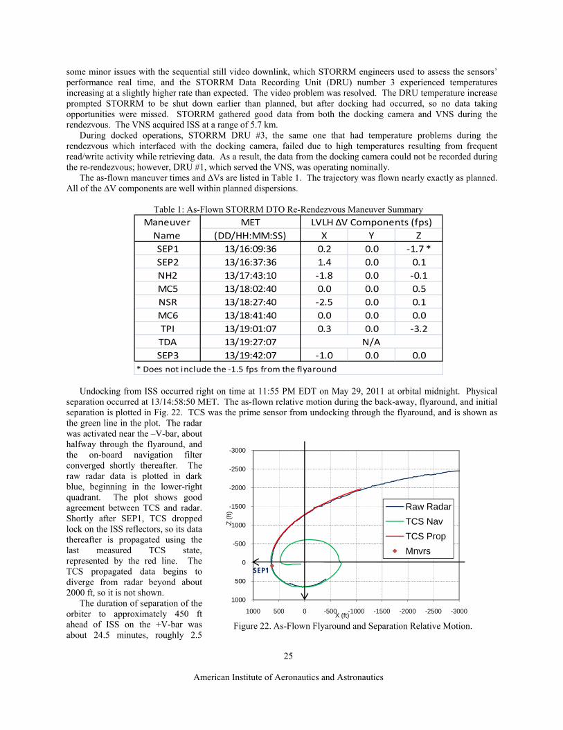
25
American Institute of Aeronautics and Astronautics
Figure 22. As-Flown Flyaround and Separation Relative Motion.
-3000
-2500
-2000
-1500
-1000
-500
0
500
1000
-3000-2500-2000-1500-1000-50005001000
Z (
ft)
X (ft)
Raw Radar
TCS Nav
TCS Prop
Mnvrs
SEP1
some minor issues with the sequential still video downlink, which STORRM engineers used to assess the sensors’ performance real time, and the STORRM Data Recording Unit (DRU) number 3 experienced temperatures increasing at a slightly higher rate than expected. The video problem was resolved. The DRU temperature increase prompted STORRM to be shut down earlier than planned, but after docking had occurred, so no data taking opportunities were missed. STORRM gathered good data from both the docking camera and VNS during the rendezvous. The VNS acquired ISS at a range of 5.7 km.
During docked operations, STORRM DRU #3, the same one that had temperature problems during the rendezvous which interfaced with the docking camera, failed due to high temperatures resulting from frequent read/write activity while retrieving data. As a result, the data from the docking camera could not be recorded during the re-rendezvous; however, DRU #1, which served the VNS, was operating nominally.
The as-flown maneuver times and ∆Vs are listed in Table 1. The trajectory was flown nearly exactly as planned. All of the ∆V components are well within planned dispersions.
Table 1: As-Flown STORRM DTO Re-Rendezvous Maneuver Summary
MET
(DD/HH:MM:SS) X Y Z
SEP1 13/16:09:36 0.2 0.0 ‐1.7 *SEP2 13/16:37:36 1.4 0.0 0.1
NH2 13/17:43:10 ‐1.8 0.0 ‐0.1MC5 13/18:02:40 0.0 0.0 0.5
NSR 13/18:27:40 ‐2.5 0.0 0.1
MC6 13/18:41:40 0.0 0.0 0.0
TPI 13/19:01:07 0.3 0.0 ‐3.2TDA 13/19:27:07
SEP3 13/19:42:07 ‐1.0 0.0 0.0
LVLH ∆V Components (fps)
N/A
Maneuver Name
* Does not include the ‐1.5 fps from the flyaround Undocking from ISS occurred right on time at 11:55 PM EDT on May 29, 2011 at orbital midnight. Physical
separation occurred at 13/14:58:50 MET. The as-flown relative motion during the back-away, flyaround, and initial separation is plotted in Fig. 22. TCS was the prime sensor from undocking through the flyaround, and is shown as the green line in the plot. The radar was activated near the –V-bar, about halfway through the flyaround, and the on-board navigation filter converged shortly thereafter. The raw radar data is plotted in dark blue, beginning in the lower-right quadrant. The plot shows good agreement between TCS and radar. Shortly after SEP1, TCS dropped lock on the ISS reflectors, so its data thereafter is propagated using the last measured TCS state, represented by the red line. The TCS propagated data begins to diverge from radar beyond about 2000 ft, so it is not shown.
The duration of separation of the orbiter to approximately 450 ft ahead of ISS on the +V-bar was about 24.5 minutes, roughly 2.5

26
American Institute of Aeronautics and Astronautics
Figure 23. As-Flown Re-Rendezvous Relative Motion.
-4000
-3000
-2000
-1000
0
1000
2000
3000
4000
5000
6000
-40000-30000-20000-1000001000020000
Z (
ft)
X (ft)
Raw Radar
TCS Nav
TCS Prop
Mnvrs
SEP1
SEP2 NH2
NSR
SEP3
TPI
TDAV‐Bar
R‐Bar
MC5
MC6
minutes less than the nominally planned 27 minute separation. Experience during crew training sessions and simulations prepared the Mission Control team to expect that. The crew had been given the guidelines that 27 ± 5 minutes would be acceptable for that phase to allow the SEP2 maneuver ∆V adjustment to set up the proper lighting for the STORRM VNS. As analysis predicted, the quick separation resulted in a 0.1 fps reduction from the pre-undocking SEP2 ∆V computation. Endeavour then performed the flyaround. The crew activated the rendezvous radar about half way through the flyaround. It came up successfully and worked throughout the re-rendezvous, so there was no need to enact the radar-failed contingencies.
The resultant ∆V of the post-flyaround trajectory and SEP1 burn was about 0.2 fps larger than the predicted 3.0 fps. This slight over-burn negated the small reduction in SEP2 ∆V from the slightly early start of the flyaround and subsequent SEP1 TIG to produce a targeted SEP2 ∆V equal to the pre-undock prediction of 1.5 fps. The targeting solutions based on radar navigation data varied from 1.47 fps to 1.60 fps during the period between SEP1 and SEP2, but ended up at 1.52 fps at the time of final targeting. The crew slightly under-burned the VGOs in both axes, as is typically the case for multi-axis maneuvers, since they normally burn down to the trim limits. The residual ∆Vs were about 0.1 in both axes, so the final separation rate was a little slower than planned.
The slower rate between SEP2 and NH2 reduced the range at which NH2 would be executed by about 2000 ft. Additionally, a non-zero radial (Z-axis) component appeared in the NSR ∆V in the integrated maneuver plan for the remaining post-SEP2 re-rendezvous maneuvers. Ideally, NSR should be a pure retrograde burn. Initially, this radial component was -1.4 fps. However, over the next 35 minutes, that figure steadily decreased to -0.4 fps. A negative Z-component is up in the LVLH frame. The most likely explanation for the reduction in the magnitude of the radial component on NSR is that the VRCS attitude hold produced some energy growth in Endeavour’s orbit, raising the ∆H of the NH2 burn. This energy growth is an expected and observed result of VRCS attitude hold during rendezvous operations in a target-track attitude when approaching the target vehicle from behind. In this case, it was beneficial, since it caused the NSR Z-component to decrease. The final NH2 ∆V was a pure retrograde 1.8 fps and the crew trimmed it nicely to 0.03 fps in VGO X and 0.05 fps in VGO Z. The full as-flown re-rendezvous trajectory is plotted in Fig. 23.

27
American Institute of Aeronautics and Astronautics
Figure 24. As-Flown Post-TPI Relative Motion.
-1000
0
1000
2000
3000
4000
5000
-8000-6000-4000-20000200040006000
Z (
ft)
X (ft)
Raw Radar
TCS Nav
MnvrsSEP3
TPI
TDAV‐Bar
R‐Bar
The MC5 was a relatively small 0.6 fps total ∆V. The majority of it was a positive 0.55 fps in the radial component, meaning that the predicted NSR position was perfect in the downrange component, but was a little high, meaning the ∆H was smaller than targeted. The MC5 would correct that and the maneuver plan indicated that the radial component on the NSR maneuver had gone away due to the smaller ∆H.
The final NSR solution was almost purely retrograde at 2.5 fps, with a negligible radial component, meaning MC5 had done its job perfectly. The relative position of the NSR was -21411 ft in X and 4524 ft in Z according to raw radar data, extremely close to the targeted -21163 ft in X and 4600 ft in Z. In fact, the NSR position and execution were so good that the MC6 solution was below the trim limits in all axes and it was declared a no-burn. The coelliptic trajectory was nearly perfect. There was a slow drift downward, beginning from a ∆H of 4524 ft at NSR and ending with 4733 ft at TPI.
The final TPI solution TIG slip was 33 seconds early, indicating that on average the coelliptic trajectory was slightly lower than the targeted 4600 ∆H, but well within expected dispersions. The total ∆V was 3.4 fps. With the thrust direction nearly along the line of sight to ISS, that put greater than 2.0 fps in both the X and Z axes. The execution of the maneuver itself was somewhat less than optimal. It appeared that the crew switched the DAP from pulse to norm in those axes just after TIG and actually began the burn a few seconds later. That, combined with the usual cross-coupling associated with burning relatively large component VGOs, caused the total duration of the maneuver to be about one minute.
The initial plots of the coasting trajectory showed TDA on the opposite side of the R-bar. However, as TCS data came in to RPOP and the RPOP filter converged, the final stall point appeared to be close to 100 ft behind ISS. The actual stall position was at a range of 952 ft from ISS, -83 ft X, -39 ft Y, and 947 ft Z, according to TCS data, as shown in Fig. 24. The target position was -333 ft X and 1000 ft Z. The late completion of the TPI maneuver was most likely the largest contributor to the small offset in X position from the target point.
The 1.0 fps SEP3 maneuver was performed about 15 minutes later, and a safe separation rate was attained. Overall, the re-rendezvous trajectory was nearly perfect. All of the small dispersions experienced were well within the predicted 3σ values and the trajectory gave the STORRM sensors a very close approximation to the planned Orion rendezvous trajectory.
X. Conclusion The STORRM DTO re-rendezvous design was refined over about two years, from early conceptual mission
evaluation work to the FRR design cycle. It was tested in engineering simulation Monte Carlo runs, in man-in-the-loop simulation runs involving the entire trajectory operations team, in flight-following mode during the undocking of previous flights, and in fully integrated shuttle simulations involving the entire MCC flight control team and crew. The trajectory, procedures, and flight control team were all fully prepared to execute this DTO and get a good flight test of the Orion relative navigation sensors.
Along the way, a number of challenges were overcome. The re-rendezvous was successfully inserted into the busy undocking day timeline. The flyaround was preserved to allow for photography of ISS, which provides both important engineering imagery and beautiful pictures of the impressive structure. The operations team learned how to manage lighting requirements while maintaining the necessary relative motion geometries to provide all desired

28
American Institute of Aeronautics and Astronautics
STORRM sensor measurement opportunities. Finally, the team learned lessons not only about the Orion trajectory for possible future use but some things about the Space Shuttle orbiter itself, even as the program was concluding.
A secondary benefit of flying the STORRM re-rendezvous was the chance to fly the actual Orion rendezvous trajectory, as it was planned at the time of the STS-134 design. This was an opportunity to get flight experience performing a new rendezvous profile, which provided a valuable data point to take forward to trajectory planning for future crewed rendezvous missions. This makes the second to last shuttle flight home to two firsts for the Space Shuttle Program – the testing of advanced relative navigation sensors for Orion on orbit and the flight of a new rendezvous trajectory for the Space Shuttle.
The re-rendezvous was executed nearly flawlessly. The STORRM DTO met all of its major objectives and the Orion coelliptic rendezvous profile has now been proven in flight. The contingency planning for this flight has also afforded the ability to develop the GPS based SPOT relative navigation capabilities, which may become a relative navigation data source on future vehicles. This makes STS-134 a pivotal link from the long and successful history of one program to the promise and potential of crewed space flights of the future.

29
American Institute of Aeronautics and Astronautics
Acknowledgments
I would like to thank the following people, who have contributed in some way to the STORRM DTO preparations, the mission, or the trajectory design. Roger Rojas/JSC-DM32 is the lead Flight Dynamics Officer on STS-134 and my NASA sponsor for this paper. Thank you, Roger, for all of your flight procedures preparation and especially for your review and sponsorship of this paper. Dave Harshman/JSC-DM34 is the lead Rendezvous Guidance and Procedures Officer on STS-134. I would like to thank Dave for always asking the tough questions about why I did what I did and challenging me to prove that what I did is the best way to do it, as well as for providing the as-flown trajectory data. Also, thank you Nick O’Dosey/Barrios Technology, the STS-134 Rendezvous Flight Data File Book Manager, for your patience with so many procedure changes as the design and operations concept evolved.
Thank you Heather Hinkle/JSC-EG6, the STORRM DTO Principal Investigator, and Sean McGuire/Jacobs Engineering, Deputy STORRM DTO Principal Investigator, for providing the STORRM requirements and so clearly defining the sensors’ constraints and capabilities and the boundaries and priorities of the data-taking periods. I would also like to thank Lowell Benishek and David Yang, Orbit IGN&C, Boeing Space Exploration, for inspiring the Lambert targeting of the NSR maneuver. I had not considered this possibility until their simulation showed that it worked.
Also, I would like to thank the United Space Alliance Flight Design Team. Bill Summa, STS-134 Prox Ops Designer, designed the post-TPI braking gates. Kris Pettinger, STS-134 Rendezvous Analyst, helped configure the rendezvous trainer, which was used extensively to design the trajectory and to perform “mini-simulations” with the entire trajectory flight control team. Those “mini-sims” were instrumental in defining and continuously refining the re-rendezvous real time procedures. Kris also wrote the script that made it possible to use TCS relative states to build orbiter inertial states, which could be uplinked to the orbiter and be used for SEP2 targeting on the ground. John Hallstrom, STS-134 Target, also helped with the rendezvous trainer and provided independent validation of maneuver targeting during the “mini-sims”, confirming that ground targeting and on-board targeting methods agreed with each other. Brian Yarbrough, Rendezvous Technical Integration Group Lead and STS-134 Profile Support, got the re-rendezvous trajectory targeting parameters that go into the shuttle Flight Software approved by the board and into the flight load.
Finally, I would also like to thank Patrick Zimmerman/United Space Alliance, STS-134 Navigator, for providing the data collection, analysis, and covariance matrices for the SPOT relative navigation trajectory analysis. Thank you as well to Dave Danemiller/JSC-DM3 and John Goodman/United Space Alliance for reviewing the SPOT analysis. John also extensively reviewed this paper and made significant contributions to its format. And thank you to Ed Gonzalez/JSC-DM32 and John Fields/JSC-DM11 for reviewing this paper and helping me navigate through NASA’s Scientific Technical Information Export Control process.
References
1Goodman, John L., “History of Space Shuttle Rendezvous and Proximity Operations,” AIAA Journal of Spacecraft and Rockets, Vol. 43, No. 5, Sept.-Oct. 2006, pp. 944-959.
2Hansen, Dave, “Development Test Objective-703 STORRM, Integration Plan”, NSTS 21551, Rev. A, NASA Johnson Space Center, February 2010.
3Bacher, Jim, “Orion - ISS FD1 Rendezvous Reference Trajectory (Rev 3)”, FltDyn-CEV-10-93, July 22, 2010. 4Sip, Megan, “Orion - ISS FD3 Rendezvous Reference Trajectory (Rev 3)”, FltDyn-CEV-10-41, March 12,
2010. 5Goodman, John L., “Space Shuttle Navigation in the GPS Era”, Proceedings of the National Technical Meeting
2001, Institute Of Navigation, Long Beach, CA, January 22-24, 2001, pages 709-724. 6Shuttle Operational Data Book, NSTS-08934, NASA Johnson Space Center.

AIAA Space 2011 Conference & ExpositionSeptember 27-29, 2011
Designing the STS-134 Re-Rendezvous:A Preparation for Future Crewed
Rendezvous Missions
Timothy D. StuitUnited Space Alliance, LLC
Houston, TX 77058
Page 1AIAA Space 2011 Conference & ExpositionSeptember 27-29, 2011
Agenda• STORRM DTO Definition and Purpose• Re-rendezvous Trajectory Overview• Details of the Re-rendezvous Trajectory Design• Design Challenges and Solutions• Operational Contingency Plans• Flight Results

Page 2AIAA Space 2011 Conference & ExpositionSeptember 27-29, 2011
STORRM DTO• STORRM – Sensor Test for Orion Relative Navigation Risk Mitigation• DTO – Detailed Test Objective• Purpose: To test new Orion (MPCV – Multi-Purpose Crew Vehicle) relative
navigation sensors– Docking Camera– Vision Navigation Sensor (VNS)
• STORRM sensors took data during the STS-134:– Rendezvous and docking with ISS– Re-Rendezvous after undocking (replicates the Orion rendezvous
trajectory)

Page 3AIAA Space 2011 Conference & ExpositionSeptember 27-29, 2011
Shuttle Rendezvous• Stable Orbit Rendezvous (Performed during STS-134 rendezvous and docking)
0
5000
10000
15000
20000
25000
30000
35000
40000
45000
50000
-300000-250000-200000-150000-100000-500000
Z (ft
)
X (ft)
Ti NC4
R-Bar
V-Bar
NCC
MC1MC4MC3
MC2
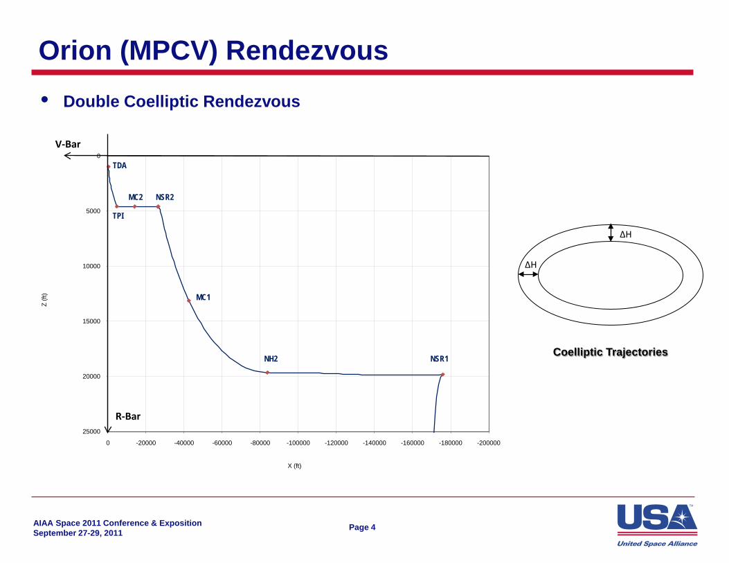
Page 4AIAA Space 2011 Conference & ExpositionSeptember 27-29, 2011
Orion (MPCV) Rendezvous• Double Coelliptic Rendezvous
∆H
∆H
Coelliptic Trajectories
0
5000
10000
15000
20000
25000
-200000-180000-160000-140000-120000-100000-80000-60000-40000-200000
Z (ft
)
X (ft)
NSR1
NSR2
NH2
TPI
MC1
MC2
V-Bar
R-Bar
TDA

Page 5AIAA Space 2011 Conference & ExpositionSeptember 27-29, 2011
STORRM DTO Re-Rendezvous• Re-rendezvous performed after undocking from ISS• Designed to replicate the second coelliptic portion of the Orion trajectory• Test VNS acquisition on the coelliptic inside of 6 km (~20,000 ft)• Get measurements in vehicle relative geometries similar to those expected in
the Orion trajectory

Page 6AIAA Space 2011 Conference & ExpositionSeptember 27-29, 2011
STORRM DTO Re-Rendezvous Relative MotionZ-
axis
X-axis
SEP1
SEP2NH2
NSR
SEP3
TPI
TDA
V-Bar
R-Bar
MC5
MC6

Page 7AIAA Space 2011 Conference & ExpositionSeptember 27-29, 2011
Re-Rendezvous Details• Undocking – On Flight Day 15, at orbital midnight to set up desired lighting
conditions during the re-rendezvous• Flyaround – Standard maneuver following shuttle undockings to photograph
ISS current state and condition• SEP1 – Separation Maneuver #1
– Pre-established ∆V of 1.5 fps radial up to begin departure from ISS– Crew deflects the Translational Hand Controller (THC) for 6 seconds– Same as typical shuttle separation procedure
• SEP2 – Separation Maneuver #2– Performed 28 minutes after SEP1– Ground targeted ΔV using on-board radar navigation– Establishes safe long-term relative motion away from ISS– Modified for STORRM re-rendezvous to target the desired downrange
distance at NSR
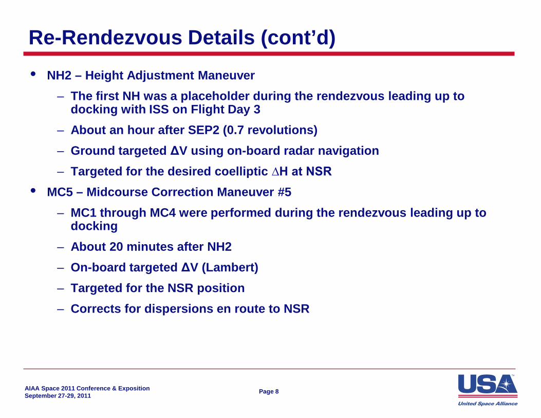
Page 8AIAA Space 2011 Conference & ExpositionSeptember 27-29, 2011
Re-Rendezvous Details (cont’d)• NH2 – Height Adjustment Maneuver
– The first NH was a placeholder during the rendezvous leading up to docking with ISS on Flight Day 3
– About an hour after SEP2 (0.7 revolutions)– Ground targeted ΔV using on-board radar navigation– Targeted for the desired coelliptic ∆H at NSR
• MC5 – Midcourse Correction Maneuver #5– MC1 through MC4 were performed during the rendezvous leading up to
docking– About 20 minutes after NH2– On-board targeted ΔV (Lambert)– Targeted for the NSR position– Corrects for dispersions en route to NSR

Page 9AIAA Space 2011 Conference & ExpositionSeptember 27-29, 2011
Re-Rendezvous Details (cont’d)• NSR – Coelliptic Maneuver
– Establishes the coelliptic portion of the trajectory– 25 minutes after MC5– On-board targeted ΔV (Lambert)– Targeted for the desired TPI position with a transit time of 34 minutes
• MC6 – Midcourse Correction Maneuver #6– 14 minutes after NSR– On-board targeted ΔV (Lambert)– Corrects for dispersions en route to TPI

Page 10AIAA Space 2011 Conference & ExpositionSeptember 27-29, 2011
Re-Rendezvous Details (cont’d)• TPI – Terminal Phase Initiation Maneuver
– About 20 minutes after MC6– Targets the TDA position– On-board targeted ΔV (Lambert)– The flight software computes the time of the burn from its estimation of
when the ISS will be 42° above the local horizontal• Ensure coasting trajectory to TDA follows the planned reference
trajectory• Automatically adjusts for ΔH dispersions
• Braking Gates– Range rate limits at ranges of 2000, 1500, 1000, and 600 ft– If closing rate exceeds limit, the crew commands braking pulses until the
rate limit is satisfied

Page 11AIAA Space 2011 Conference & ExpositionSeptember 27-29, 2011
Re-Rendezvous Details (cont’d)• TDA – Transition to Docking Axis
– The point in the trajectory where Orion would translate to the axis of the docking port to which it would dock
– The trajectory is designed to stall about 26 minutes after TPI– For STORRM, no maneuver is performed (orbital mechanics initiates
separation)– Targeted location: X = -333 ft, Z = 1000 ft
• SEP3 – Separation Maneuver #3– Pre-established ∆V of 1.0 fps retrograde– 41 minutes after TPI (~15 minutes after TDA)– Increases the separation rate to ensure safe long-term relative motion

Page 12AIAA Space 2011 Conference & ExpositionSeptember 27-29, 2011
Trajectory Dispersion AnalysisZ-
axis
X-axis
SEP1
SEP2
NH2
NSRTPI
TDA
V-Bar
R-Bar
MC5
MC6
• Dispersions arise from errors and uncertainties in:
– Navigated states– Relnav sensor
alignment and accuracy
– IMU biases and sensed acceleration
– Engine gimbal angles– Attitude control and
deadbands
• Ellipses represent 3σdispersions for each maneuver
• SEP2, NH2, and MC5 combine to bring dispersions well under control by NSR
Page 13AIAA Space 2011 Conference & ExpositionSeptember 27-29, 2011
Contingency Plans• The trajectory operations team had to be prepared for unplanned events…
– Late Undocking / Separation Timing Variability– Vehicle Systems Failures– STORRM Instrument Problems– Failed Radar
• … and had these options at its disposal– STORRM Lighting Window– SEP2 ∆V Adjustment– NH2 Delay– NSR Delay– Breakouts– GPS Relative Navigation Backup Plan
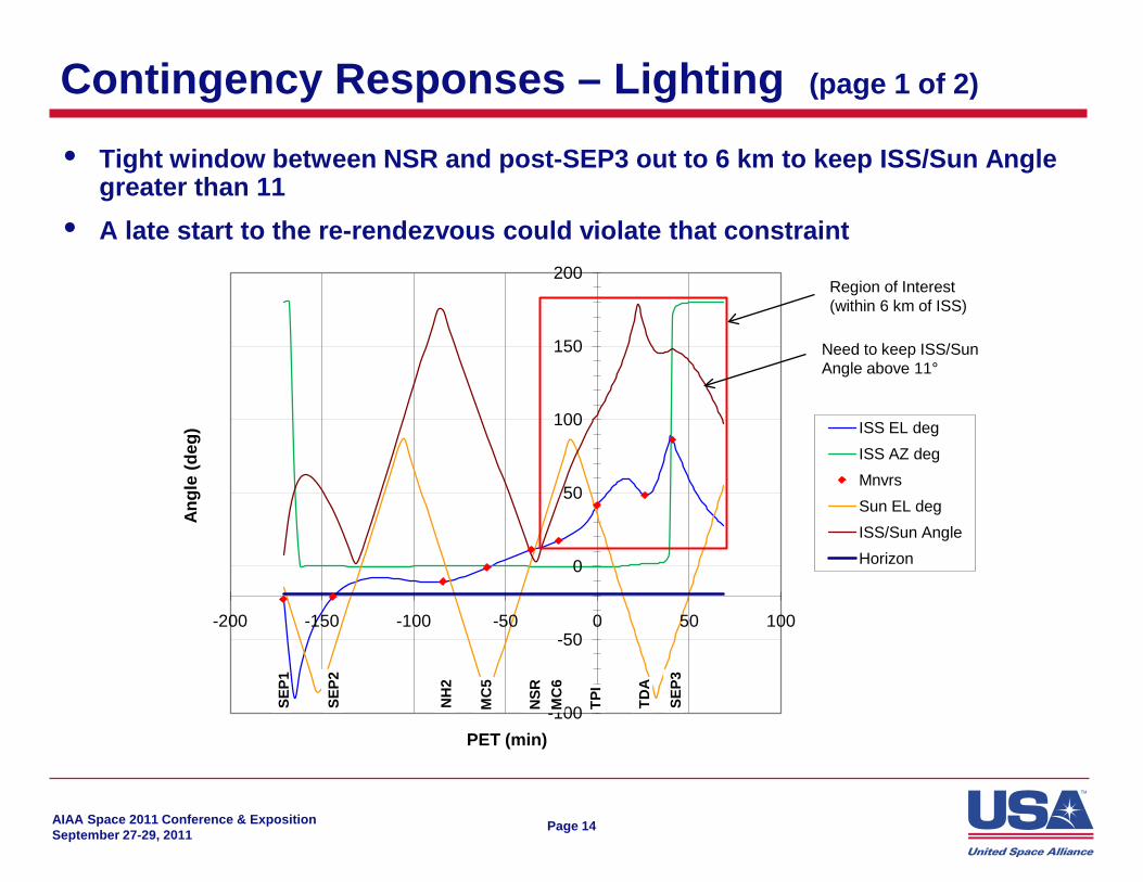
Page 14AIAA Space 2011 Conference & ExpositionSeptember 27-29, 2011
Contingency Responses – Lighting (page 1 of 2)
-100
-50
0
50
100
150
200
-200 -150 -100 -50 0 50 100
Angl
e (d
eg)
PET (min)
ISS EL degISS AZ degMnvrsSun EL degISS/Sun AngleHorizon
TPI
TDA
SEP3
NSR
MC
6
MC
5
NH
2
SEP2
SEP1
Region of Interest(within 6 km of ISS)
Need to keep ISS/SunAngle above 11°
• Tight window between NSR and post-SEP3 out to 6 km to keep ISS/Sun Angle greater than 11
• A late start to the re-rendezvous could violate that constraint

Page 15AIAA Space 2011 Conference & ExpositionSeptember 27-29, 2011
Contingency Responses – Lighting (page 2 of 2)
• Lighting Window– Allows the start the re-rendezvous to be up to 14 minutes late
• SEP2 ∆V Adjustment– SEP2 ∆V can be adjusted to compensate for SEP1 time of as much as ±15
minutes from planned• Early SEP1 smaller ∆V longer transfer time to NH2• Late SEP1 larger ∆V shorter transfer time to NH2
Z-ax
is
X-axis
SEP1
SEP2NH2
NSRTPI
TDA
V-Bar
R-Bar
MC5
MC6
• NH2 Delay– For large delays to the start of the
re-rendezvous, we could delay NH2 to target TPI to be on the next revolution

Page 16AIAA Space 2011 Conference & ExpositionSeptember 27-29, 2011
Contingency Responses – System Failures• If there’s a problem with vehicle or STORRM systems, we could delay to the
next revolution to maintain lighting constraints• There are two options
– NH2 Delay for a full revolution– NSR Delay
Z-ax
is
X-axis
SEP1
SEP2NH2
NSR
SEP3
TPI
TDA
V-Bar
R-Bar
MC5
MC6
Page 17AIAA Space 2011 Conference & ExpositionSeptember 27-29, 2011
Contingency Responses – Abort• If a critical system can’t be fixed, we could break out of the re-rendezvous• Breakout = Discontinue the planned trajectory and separate to a safe distance• Passive breakout
– From SEP2 through NH2 (continue coast away from ISS)– From NSR through TPI (stay on the coelliptic)
• Breakout maneuver– 3 fps posigrade ∆V after NH2 while above the V-bar– 3 fps retrograde ∆V
• Before NSR while below the V-bar• After TPI
Page 18AIAA Space 2011 Conference & ExpositionSeptember 27-29, 2011
Contingency Responses – Radar Failure• If radar fails, need an alternate source of navigation data• The orbiter and ISS have GPS receivers
– Used for absolute navigation– Never before used for relative navigation
• A study determined that we could use GPS data that have been smoothed via a ground processor, the Spacecraft Position Optimal Tracking (SPOT) program

Page 19AIAA Space 2011 Conference & ExpositionSeptember 27-29, 2011
As-Flown Re-Rendezvous Relative Motion
-4000
-3000
-2000
-1000
0
1000
2000
3000
4000
5000
6000
-40000-30000-20000-1000001000020000
Z (ft
)
X (ft)
Raw Radar
TCS Nav
TCS Prop
Mnvrs
SEP1
SEP2 NH2
NSR
SEP3
TPI
TDAV-Bar
R-Bar
MC5
MC6

Page 20AIAA Space 2011 Conference & ExpositionSeptember 27-29, 2011
As-Flown Separation and Flyaround
-3000
-2500
-2000
-1500
-1000
-500
0
500
1000
-3000-2500-2000-1500-1000-50005001000
Z (ft
)
X (ft)
Raw Radar
TCS Nav
TCS Prop
Mnvrs
SEP1

Page 21AIAA Space 2011 Conference & ExpositionSeptember 27-29, 2011
As-Flown Re-Rendezvous Approach
-1000
0
1000
2000
3000
4000
5000
-8000-6000-4000-20000200040006000
Z (ft
)
X (ft)
Raw Radar
TCS Nav
Mnvrs
SEP3
TPI
TDA
V-Bar
R-Bar

Page 22AIAA Space 2011 Conference & ExpositionSeptember 27-29, 2011
As-Flown Re-Rendezvous Maneuvers
MET(DD/HH:MM:SS) X Y Z
SEP1 13/16:09:36 0.2 0.0 -1.7 *SEP2 13/16:37:36 1.4 0.0 0.1NH2 13/17:43:10 -1.8 0.0 -0.1MC5 13/18:02:40 0.0 0.0 0.5NSR 13/18:27:40 -2.5 0.0 0.1MC6 13/18:41:40 0.0 0.0 0.0TPI 13/19:01:07 0.3 0.0 -3.2TDA 13/19:27:07SEP3 13/19:42:07 -1.0 0.0 0.0
∆V Components (fps)
N/A
Maneuver Name
* Does not include the -1.5 fps from the flyaround

Page 23AIAA Space 2011 Conference & ExpositionSeptember 27-29, 2011
Conclusion• The STS-134 STORRM DTO re-rendezvous was a resounding success in a
number of aspects• Space Shuttle firsts
– Testing of new, advanced set of relative navigation sensors– First coelliptic rendezvous trajectory
• Provided the opportunity to investigate GPS relative navigation feasibility• Lessons learned about the Orion/MPCV trajectory during the design process• Flight tested the planned Orion/MPCV rendezvous trajectory• Serves as a link from the Space Shuttle Program to crewed rendezvous
missions of the future