desigo i/o module system - siemens.be · 4/54 siemens building technologies technical basics:...
TRANSCRIPT

CM2Z8102en30.07.2002
Siemens Building TechnologiesBuilding Automation
DESIGO
I/O module systemTechnical basics

2/54
Siemens Building Technologies Technical basics: DESIGO I/O module system CM2Z8102enBuilding Automation 30.07.2002

3/54
Siemens Building Technologies Technical basics: DESIGO I/O module system CM2Z8102enBuilding Automation Table of contents 30.07.2002
Table of contents
1 Introduction ...................................................................................................5
1.1 Revision history.............................................................................................5
1.2 About this document .....................................................................................5
1.3 Document contents .......................................................................................6
2 Safety notes ..................................................................................................7
2.1 System-specific regulations ..........................................................................7
2.2 Device-specific regulations ...........................................................................9
3 The DESIGO I/O module system ................................................................11
3.1 System architecture.....................................................................................11
3.2 Module functions, data and types ...............................................................12
3.3 Type code for I/O modules..........................................................................13
3.4 Terminology.................................................................................................14
3.5 P-bus and supplies......................................................................................14
4 Data and signal traffic .................................................................................15
4.1 Basic functions of building automation and control .....................................15
4.2 The flow of information in the I/O module system .......................................16
4.3 The P-bus....................................................................................................17
4.4 The I/O block...............................................................................................17
4.5 The I/O module............................................................................................17
4.6 The I/O point................................................................................................18
4.7 The I/O channel...........................................................................................18
4.8 I/O channel and I/O module ........................................................................19
4.9 I/O channel and I/O point ............................................................................19
4.10 I/O module addressing ................................................................................20
5 Structure and design of I/O modules...........................................................21
6 Connection diagrams ..................................................................................23
6.1 Internal diagrams.........................................................................................23
6.2 Terminal labelling for I/O modules...............................................................24
7 Engineering notes .......................................................................................25
7.1 Supplementary information on safety..........................................................25
7.2 Electromagnetic compatibility (EMC) ..........................................................26
7.3 Operating voltage AC 24 V..........................................................................26
7.4 Transformer sizing.......................................................................................26
7.5 Load units of the I/O modules .....................................................................26
7.6 Module response.........................................................................................26

4/54
Siemens Building Technologies Technical basics: DESIGO I/O module system CM2Z8102enBuilding Automation Table of contents 30.07.2002
7.7 I/O module and accessories layout ............................................................ 27
8 Wiring notes................................................................................................ 29
8.1 General wiring information.......................................................................... 29
8.2 Wiring AC 24 V supply lines ....................................................................... 30
8.3 Wiring sample for AC 24 V supply.............................................................. 32
8.4 P-bus wiring notes ...................................................................................... 33
8.5 Wiring notes for the remote P-bus.............................................................. 34
8.6 Connecting the field devices to the I/O modules ........................................ 34
8.7 Wiring signalling and counter value modules ............................................. 35
8.8 Wiring measured value modules ................................................................ 36
8.8.1 Passive resistance sensors and resistance transmitters............................ 36
8.8.2 Measured value modules with active sensors ............................................ 39
8.9 Switching modules...................................................................................... 39
8.10 Positioning modules ................................................................................... 40
9 Commissioning notes ................................................................................. 41
10 Technical data ............................................................................................ 43
10.1 General data............................................................................................... 43
10.2 I/O module data .......................................................................................... 44
10.3 I/O bars....................................................................................................... 46
10.4 P-bus cable................................................................................................. 46
11 Appendix..................................................................................................... 47
11.1 Dimensions................................................................................................. 47
11.2 Referenced documents .............................................................................. 48
Feedback form .............................................................................................................. 51

5/54
Siemens Building Technologies Technical basics: DESIGO I/O module system CM2Z8102enBuilding Automation Introduction 30.07.2002
1 Introduction1.1 Revision history
This document represents a complete review and replacement of the previousdocument CM2N8102 "Basic Data of the I/O Module System“ for UNIGYR andVISONIK.This document also carries the DESIGO system name the contents are neutral,however, and still apply to the existing building automation and control systemsVISONIK and UNIGYR.
The following items have changed from the previous edition of 01.09.2000:
Changes Chapter Pages
"Siemens Building Technologies,Building Automation" (short form: SBTBAU) replaces "Landis & Staefa"
throughout document various
"automation station" replaces "processunit"
throughout document various
Interface modules PTE-MBUS.60,PTM59.20V01, PTE-ASD.20 added totable "Module functions, data andtypes"
3.2 12
Table column "DESIGO"supplemented by "2.x" (i.e. version)
3.2 12
1.2 About this document
This document targets product management and engineering in the market areas.
This document provides knowledge. In addition to background information, it containsgeneral technical basics on the I/O module system, to be used in particular for earlysupport, engineering, and quality control as well as service.
This document contains all required documentation for the above target audience andpurpose.• Specialities of the individual modules and accessories are discussed only where
applicable to the overall I/O module system. Specialities of the various modules aredescribed in data sheet N8100 "I/O module range" and in the data sheets on theindividual I/O modules.
• The necessary accessories for the I/O modules such as I/O bars, module supplyblocks, labelling materials, etc. are described in data sheet N8105 "I/O modulesystem accessories".
• For comprehensive information on the I/O module functions, refer to the functionmanuals of the various systems; see section 11.2 "Referenced documents".
• Notes and extensive descriptions of the control cabinet requirements as well asallocation of the I/O modules are available in the mounting and installation guideCM2M8102en "DESIGO I/O modules and P-bus".
This document does not discuss the basics for the I/O compact units. Information andengineering notes on the I/O compact units are available in the respective data sheets(see section 11.2 "Referenced documents").
Remarks
Main audience
Purpose
Restrictions
Note

6/54
Siemens Building Technologies Technical basics: DESIGO I/O module system CM2Z8102enBuilding Automation Introduction 30.07.2002
Section 11.2 contains a list of documents on the I/O module system providing detailedinformation on engineering.
In this document, reference numbers for documents are always printed in anabbreviated form, e.g. Z8102. The complete numbers (e.g., CM2Z8102en) areavailable in section 11.2.
1.3 Document contents
This document contains basic technical information on the I/O module system. Thisdocument references the existing mounting and installation guide M8102 for requiredengineering information.
This document covers the following issues:• Safety notes• DESIGO I/O module system with information on:
– system architecture– module functions and data relative to the module type– information on the building automation and control systems
and the associated I/O modules– type code– P-bus and supply
• The data and signal traffic along with an explanation of the basic functions• Structure and design of the I/O modules• Connection diagrams and terminal labelling• Engineering notes• Wiring notes• Commissioning notes• Technical data• Dimensions• Referenced documents
In this document, the terms "process unit" (UNIGYR), "BPS" (VISONIK BuildingProcess Station) and "automation station" (DESIGO) are used interchangeably.
Referenced documents
Note
Introduction
Note

7/54
Siemens Building Technologies Technical basics: DESIGO I/O module system CM2Z8102enBuilding Automation Safety notes 30.07.2002
2 Safety notesThis chapter explains general and system-specific regulations. It also containsimportant information regarding your own safety and that of your plant.
The warning triangle to the left means that you must observe all respectively listedregulations and notes. If ignored, injuries and equipment damages may result.
Observe the following general regulations during engineering and project execution:• Electric and high-power regulations of the respective country• Other mandatory country regulations• House installation regulations of the respective country• Regulations by the energy supplier• Diagrams, cable lists, dispositions, specifications and instructions as per the
customer or the engineering business• Third-party regulations from, e.g., the general contractors or building contractors
2.1 System-specific regulations
Electrical safety in Siemens building automation and control systems primarily dependson extra-low voltage with safe isolation from mains voltage.
Depending on the earthing of extra-low voltage, SELV or PELV applications as perHD384 "Electrical plants in buildings" result:Unearthed = Safety Extra-Low Voltage SELVEarthed = Protection by Extra-Low Voltage PELV
Safety for the units is ensured by (among other aspects):• Supply of AC 24 V extra-low voltage as per SELV or PELV• Double isolation between AC 230 V mains voltage and SELV/PELV circuits• Microfuses in the module supply block• Back-up fuses of the I/O bars
Please note the specific regulations on electric wiring of the I/O module groups as perthe following sections.
Observe the following for grounding G0:• As a rule, earthing as well as non-earthing of G0 is permissible for AC 24 V
operating voltage. However, observe all local regulations and customary procedures• For functional reasons, earthing may be required or not permissible.
• As a rule, ground AC 24 V systems, if not otherwise indicated by the manufacturer.• To avoid earth loops, connect systems with PELV to the earth at only one end in
the system, normally at the transformer, unless otherwise specified• You can also prevent earth loops through connected PC interfaces (PC tools) via
electrical isolation
Please observe thefollowing notes
Safety note
General regulations
Safety
SELV, PELV
Unit safety
Earthing ofG0 (system neutral)
Recommendation onearthing G0
8/54
Siemens Building Technologies Technical basics: DESIGO I/O module system CM2Z8102enBuilding Automation Safety notes 30.07.2002
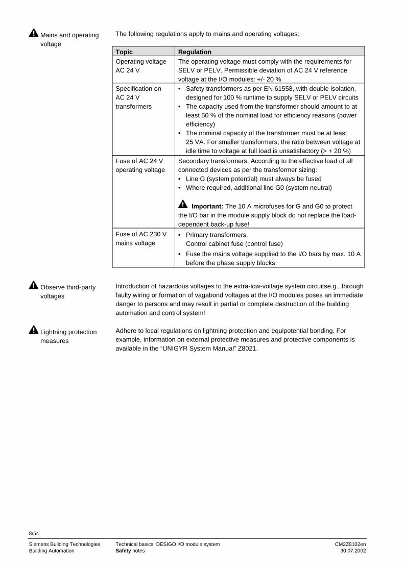
The following regulations apply to mains and operating voltages:
Topic RegulationOperating voltageAC 24 V
The operating voltage must comply with the requirements forSELV or PELV. Permissible deviation of AC 24 V referencevoltage at the I/O modules: +/- 20 %
Specification onAC 24 Vtransformers
• Safety transformers as per EN 61558, with double isolation,designed for 100 % runtime to supply SELV or PELV circuits
• The capacity used from the transformer should amount to atleast 50 % of the nominal load for efficiency reasons (powerefficiency)
• The nominal capacity of the transformer must be at least25 VA. For smaller transformers, the ratio between voltage atidle time to voltage at full load is unsatisfactory (> + 20 %)
Fuse of AC 24 Voperating voltage
Secondary transformers: According to the effective load of allconnected devices as per the transformer sizing:• Line G (system potential) must always be fused• Where required, additional line G0 (system neutral)
Important: The 10 A microfuses for G and G0 to protectthe I/O bar in the module supply block do not replace the load-dependent back-up fuse!
Fuse of AC 230 Vmains voltage
• Primary transformers:Control cabinet fuse (control fuse)
• Fuse the mains voltage supplied to the I/O bars by max. 10 Abefore the phase supply blocks
Introduction of hazardous voltages to the extra-low-voltage system circuitse.g., throughfaulty wiring or formation of vagabond voltages at the I/O modules poses an immediatedanger to persons and may result in partial or complete destruction of the buildingautomation and control system!
Adhere to local regulations on lightning protection and equipotential bonding. Forexample, information on external protective measures and protective components isavailable in the “UNIGYR System Manual” Z8021.
Mains and operatingvoltage
Observe third-partyvoltages
Lightning protectionmeasures

9/54
Siemens Building Technologies Technical basics: DESIGO I/O module system CM2Z8102enBuilding Automation Safety notes 30.07.2002
2.2 Device-specific regulations
The following regulations apply to I/O modules:
Topic Regulation
Double-modules formains voltage orextra-low voltage
For safety reasons, connect only mains voltage orextra-low voltage to the same I/O module in double moduleswith inputs or outputs for mains and extra-low voltage. Thisapplies to:
• Various switching modules (PTM1..Q250..)• Signalling module with voltage inputs (PTM1.2D250)
Signalling contacts Connect only potential-free, mechanical contacts to the inputsof a signalling module.Exception: Signalling module with voltage inputs.
Manual switch Do not use the manual switch on the switching andpositioning modules for safety shutdown, e.g., during serviceand maintenance procedures.
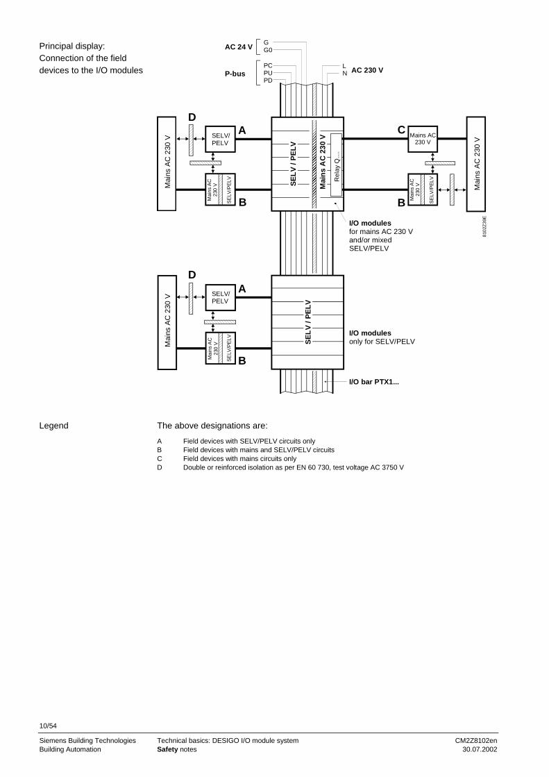
The devices must have the required isolation of voltage circuits in order to beconnected without additional isolation (see "Principal display: Connection of fielddevices to I/O modules").
Connections via the interfaces may lead to distribution of dangerous voltagesthroughout the building. For these cases, make sure that the required isolation existsand that you have observed all associated installation regulations.
The following applies to field devices and interfaces with extra-low voltage:
Topic RegulationField devicesconnected to I/Omodules
Field devices such as sensors, signalling contacts, actuators,etc. connected to extra-low voltage inputs and outputs of I/Omodules must comply with the requirements as per SELV orPELV.
Interfaces for extra-low voltage
Interfaces of peripheral devices and to other systems mustalso comply with SELV or PELV
During engineering, observe the technical data for the accessories as listed in datasheet N8105 "I/O module system accessories".
I/O modules
Connecting field devicesto the I/O modules
Devices with differingvoltage circuits
Interfaces between thevarious voltage circuits
Field devices andinterfaces
I/O moduleaccessories
10/54
Siemens Building Technologies Technical basics: DESIGO I/O module system CM2Z8102enBuilding Automation Safety notes 30.07.2002
SELV/PELV
Mai
nsA
C23
0V
SE
LV
/PE
LV
Mai
ns
AC
230
V
Mai
nsA
C23
0V
SE
LV/P
ELV
SELV/PELV
Mai
nsA
C23
0V
SE
LV/P
ELV
Mai
nsA
C23
0V
SE
LV
/PE
LV
Mai
nsA
C23
0V
SE
LV/P
ELV
Mains AC230 V
Mai
nsA
C23
0V
GG0
PCPUPD
LN AC 230 V
I/O modulesfor mains AC 230 Vand/or mixedSELV/PELV
I/O modulesonly for SELV/PELV
I/O bar PTX1...
A
B
A
B
D
DC
B
8102
Z39
E
AC 24 V
P-bus
Rel
ayQ
....
The above designations are:
A Field devices with SELV/PELV circuits onlyB Field devices with mains and SELV/PELV circuitsC Field devices with mains circuits onlyD Double or reinforced isolation as per EN 60 730, test voltage AC 3750 V
Principal display:Connection of the fielddevices to the I/O modules
Legend

11/54
Siemens Building Technologies Technical basics: DESIGO I/O module system CM2Z8102enBuilding Automation The DESIGO I/O module system 30.07.2002
3 The DESIGO I/O module system3.1 System architecture
The DESIGO I/O module system is used to convert the P-bus signals of an automationstation to field device signals and vice-versa. It consists of the I/O modules for the basicfunctions SIGNALLING; MEASURING, COUNTING, SWITCHING, and POSITIONINGas well as the I/O bar, the terminal blocks, and various accessories.
The I/O modules represent signal converters that, where meaningful, have a displayand allow for manual intervention. They also form the exit terminal bar on the I/O bar inthe control cabinet.Comment: I/O = Input/Output
The I/O module system serves as the link between the automation stations with P-busand the field devices in the building services systems.I/O modules convert the P-bus signals as required by the receiving devices or elementsand the associated functions.
N
U1
U2
M1 M2 M3
p
p
S
Building Process Station
Zeit
Datum
SW-Version
T1P-bus
P-bus
Control panel
8102
Z41
E
N Automation station with P-busT1 AC 230 V/AC 24 V transformerU1 I/O module group with internal connections to the devices in the control cabinetU2 I/O module group with external connections to field devicesP-bus Process bus for data communication between the automation station unit and the I/O modulesM1 Heating coil pumpM2 Supply air fanM3 Exhaust air fan
Brief description
Usage with automationstations
Basic system architecture
Legend
12/54
Siemens Building Technologies Technical basics: DESIGO I/O module system CM2Z8102enBuilding Automation The DESIGO I/O module system 30.07.2002
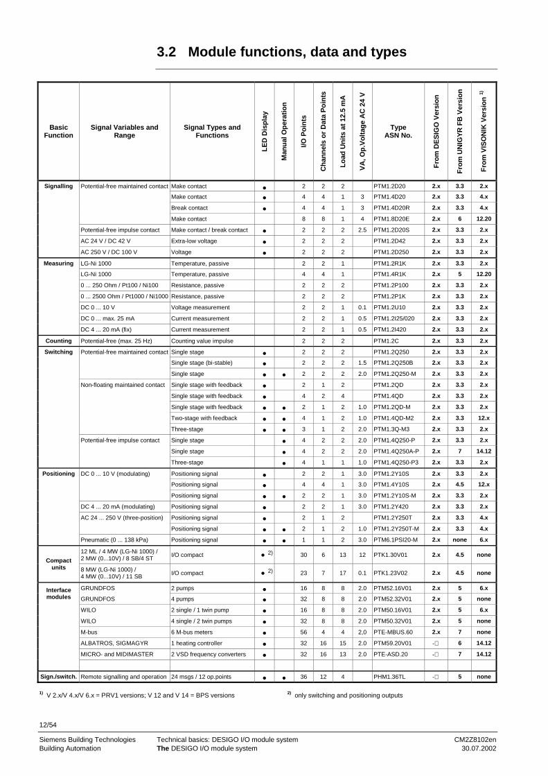
3.2 Module functions, data and types
BasicFunction
Signal Variables andRange
Signal Types andFunctions
LE
DD
isp
lay
Man
ual
Op
erat
ion
I/OP
oin
ts
Ch
ann
els
or
Dat
aP
oin
ts
Lo
adU
nit
sat
12.5
mA
VA
,Op
.Vo
ltag
eA
C24
V
TypeASN No.
Fro
mD
ES
IGO
Ver
sio
n
Fro
mU
NIG
YR
FB
Ver
sio
n
Fro
mV
ISO
NIK
Ver
sio
n1)
Signalling Potential-free maintained contact Make contact • 2 2 2 PTM1.2D20 2.x 3.3 2.x
Make contact • 4 4 1 3 PTM1.4D20 2.x 3.3 4.x
Break contact • 4 4 1 3 PTM1.4D20R 2.x 3.3 4.x
Make contact 8 8 1 4 PTM1.8D20E 2.x 6 12.20
Potential-free impulse contact Make contact / break contact • 2 2 2 2.5 PTM1.2D20S 2.x 3.3 2.x
AC 24 V / DC 42 V Extra-low voltage • 2 2 2 PTM1.2D42 2.x 3.3 2.x
AC 250 V / DC 100 V Voltage • 2 2 2 PTM1.2D250 2.x 3.3 2.x
Measuring LG-Ni 1000 Temperature, passive 2 2 1 PTM1.2R1K 2.x 3.3 2.x
LG-Ni 1000 Temperature, passive 4 4 1 PTM1.4R1K 2.x 5 12.20
0 ... 250 Ohm / Pt100 / Ni100 Resistance, passive 2 2 2 PTM1.2P100 2.x 3.3 2.x
0 ... 2500 Ohm / Pt1000 / Ni1000 Resistance, passive 2 2 2 PTM1.2P1K 2.x 3.3 2.x
DC 0 ... 10 V Voltage measurement 2 2 1 0.1 PTM1.2U10 2.x 3.3 2.x
DC 0 ... max. 25 mA Current measurement 2 2 1 0.5 PTM1.2I25/020 2.x 3.3 2.x
DC 4 ... 20 mA (fix) Current measurement 2 2 1 0.5 PTM1.2I420 2.x 3.3 2.x
Counting Potential-free (max. 25 Hz) Counting value impulse 2 2 2 PTM1.2C 2.x 3.3 2.x
Switching Potential-free maintained contact Single stage • 2 2 2 PTM1.2Q250 2.x 3.3 2.x
Single stage (bi-stable) • 2 2 2 1.5 PTM1.2Q250B 2.x 3.3 2.x
Single stage • • 2 2 2 2.0 PTM1.2Q250-M 2.x 3.3 2.x
Non-floating maintained contact Single stage with feedback • 2 1 2 PTM1.2QD 2.x 3.3 2.x
Single stage with feedback • 4 2 4 PTM1.4QD 2.x 3.3 2.x
Single stage with feedback • • 2 1 2 1.0 PTM1.2QD-M 2.x 3.3 2.x
Two-stage with feedback • • 4 1 2 1.0 PTM1.4QD-M2 2.x 3.3 12.x
Three-stage • • 3 1 2 2.0 PTM1.3Q-M3 2.x 3.3 2.x
Potential-free impulse contact Single stage • 4 2 2 2.0 PTM1.4Q250-P 2.x 3.3 2.x
Single stage • 4 2 2 2.0 PTM1.4Q250A-P 2.x 7 14.12
Three-stage • 4 1 1 1.0 PTM1.4Q250-P3 2.x 3.3 2.x
Positioning DC 0 ... 10 V (modulating) Positioning signal • 2 2 1 3.0 PTM1.2Y10S 2.x 3.3 2.x
Positioning signal • 4 4 1 3.0 PTM1.4Y10S 2.x 4.5 12.x
Positioning signal • • 2 2 1 3.0 PTM1.2Y10S-M 2.x 3.3 2.x
DC 4 ... 20 mA (modulating) Positioning signal • 2 2 1 3.0 PTM1.2Y420 2.x 3.3 2.x
AC 24 ... 250 V (three-position) Positioning signal • 2 1 2 PTM1.2Y250T 2.x 3.3 4.x
Positioning signal • • 2 1 2 1.0 PTM1.2Y250T-M 2.x 3.3 4.x
Pneumatic (0 ... 138 kPa) Positioning signal • • 1 1 2 3.0 PTM6.1PSI20-M 2.x none 6.x
12 ML / 4 MW (LG-Ni 1000) /2 MW (0...10V) / 8 SB/4 ST
I/O compact • 2) 30 6 13 12 PTK1.30V01 2.x 4.5 noneCompact
units 8 MW (LG-Ni 1000) /4 MW (0...10V) / 11 SB I/O compact • 2) 23 7 17 0.1 PTK1.23V02 2.x 4.5 none
GRUNDFOS 2 pumps • 16 8 8 2.0 PTM52.16V01 2.x 5 6.xInterfacemodules GRUNDFOS 4 pumps • 32 8 8 2.0 PTM52.32V01 2.x 5 none
WILO 2 single / 1 twin pump • 16 8 8 2.0 PTM50.16V01 2.x 5 6.x
WILO 4 single / 2 twin pumps • 32 8 8 2.0 PTM50.32V01 2.x 5 none
M-bus 6 M-bus meters • 56 4 4 2,0 PTE-MBUS.60 2.x 7 none
ALBATROS, SIGMAGYR 1 heating controller • 32 16 15 2.0 PTM59.20V01 - 6 14.12
MICRO- and MIDIMASTER 2 VSD frequency converters • 32 16 13 2.0 PTE-ASD.20 - 7 14.12
Sign./switch. Remote signalling and operation 24 msgs / 12 op.points • • 36 12 4 PHM1.36TL - 5 none
1) V 2.x/V 4.x/V 6.x = PRV1 versions; V 12 and V 14 = BPS versions 2) only switching and positioning outputs

13/54
Siemens Building Technologies Technical basics: DESIGO I/O module system CM2Z8102enBuilding Automation The DESIGO I/O module system 30.07.2002
As a rule, the I/O modules can be connected to all automation stations with P-bus,provided the automation stations' software supports all associated functions. Thevarious function descriptions and tools for the building automation and control systemsprovide all related information.
3.3 Type code for I/O modules
The type code contains information on the I/O modules in the form of a memory code.This information can be retrieved by means of the type code.The most important information is:• Signal type: Signalling (D); Measuring (I, P, R, U); Counting (C); Switching (Q),
Positioning (Y)• Number of I/O points per module (2nd digit): The total number of I/O points or load
units—which can be calculated from the number of I/O modules required for asystem—allows for an approximation of an automation station's performance class(load units); see table below "Module functions, data, and types".
• Additional manual intervention option (last digit): with switch (-M), with key (-P)
P T M 1. 2 Y10S – M
1. Letter – Product rangeP DESIGO
2. Letter – Type of productT Transducer
3. Letter – BuildM Module
1. Digit – Construction series/point1 Construction series
2. Digit – Number of I/O points/modules2 I/O points/modules (example)
The following letters:
Signal type
C Counter value impulse acquisition (count)
D20E Signalling input, contact query, without displayD20 Signalling input, contact query, display of make contact principleD20E Signalling input, contact query, without display (with DC 30 V)D20R Signalling input, contact query, display of break contact principle (inverted)D20S Signalling input, impulse contact query, with memoryD42 Signalling input, extra-low voltage query AC 24 V, max. DC 42 V (without electrical isolation)D250 Signalling input, voltage query AC 24...250 V, DC 24...100 V (with electrical isolation)
I25/...* Measured value input, current, measuring range DC 0...25 mA (full)I420 Measured value input, current, measuring range DC 4...20 mA (fixed)
P1K Measured value input, temperature sensor Pt 1000 ohms at 0 °C (= Pt 1k ohm) or 0...2500 ohmsP100 Measured value input, temperature sensor Pt 100 ohms at 0 °C or 0...250 ohms
QD Switching output, non-floating (AC 230 V) and signalling input (feedback)Q250 Switching output, potential-free AC 24...250 VQ250A Switching output, potential-free AC 24...250 V (with working contacts)Q250B Switching output, potential-free AC 24...250 V (bistable)
R1K Measured value input, temperature sensor LG-Ni 1000 ohms
U10 Measured value input, current, measuring range DC 0...10 V
Y10S Measured value input, current, modulating DC 0…10 V with positioning value memory (example)Y250T Switching output, three-position, potential-free AC 24...250 V, with stroke modelY420 Positioning output, current, modulating DC 4...20 mAPSI20 Positioning output, pneumatic, modulating 0...138 kPa (0....20 psig), (not for UNIGYR)
Manual operation –Separated by dash
– M Manual with switch ** (example)– P Manual with pressure key (PUSH)**
* Measuring range indication (range end)The measuring range is defined by inserting in the terminal block a corresponding shunt.
** Models for multi-stage motors or switching output have the number of controllable stages,e.g., M2 for two-stage output.
Usage of I/O modules
Introduction

14/54
Siemens Building Technologies Technical basics: DESIGO I/O module system CM2Z8102enBuilding Automation The DESIGO I/O module system 30.07.2002
3.4 Terminology
The terms as contained in the table header of section 3.2 "Module functions, data andtypes" are explained in the following sections:
Term SectionI/O points 4.6Channels 4.7Load units 7.5
3.5 P-bus and supplies
The signals between the I/O modules and the automation station run on the P-bus. Theautomation station sends its signals in the form of addressed, digital telegrams to theI/O modules and similarly acquires the signals from the system.
The P-bus is a serial bus, i.e., the telegram data between the automation station andthe individual I/O modules are sent and gathered in series.The P-bus consists of three lines: Data line PD, synchronous or PC clock line orreference voltage PU.
For detailed information on the P-bus, refer to data sheet N8022. For information onwiring, refer to section 8.4 "P-bus wiring notes".
The AC 24 V supplied via the module supply block is used for the following:• The module electronics' supply for a number of module types• For direct supply of actuating devices and measured value transmitters (with active
output signal) via the connecting terminals of the associated modules• As auxiliary voltage for modules with manual intervention option
Outside of the module, AC 24 V is used by the system:• as signalling voltage• to supply measuring transducers• as operating voltage for actuating devices
The module electronics normally refer to the direct supply current (reference voltagePU, DC 24 V) of the automation station via the P-bus line PU and system neutral G0. Anumber of modules having their own supply unit use AC 24 V operating voltage.
The system neutral (SN, terminal G0) represents the reference line for DC 24 V supplyvia P-bus of the I/O modules and for AC 24 V operating voltage.
The mains voltage supplied via the phase supply and the neutral supply block is usedto supply, switch, and control switching units and plant elements of a buildingautomation and control system.
P-bus signals, supply voltage, and mains voltage are supplied to the I/O bar and thus tothe I/O modules via terminal blocks.
Signal flow
P-bus (process bus)
Note
AC 24 V supply voltage
DC 24 V module supply
System neutral
AC 230 V mains voltage
Signal supply and supplyvoltage
15/54
Siemens Building Technologies Technical basics: DESIGO I/O module system CM2Z8102enBuilding Automation Data and signal traffic 30.07.2002
4 Data and signal trafficThis chapter explains both terminology and basic functions required to understand thestructures of the DESIGO I/O module system along with the integrated P-bus as themain data transmission vehicle. Refer to the function manuals of the respective buildingautomation and control systems for detailed information on this topic (see section 11.2"Referenced documents“).
The terminology used to label the individual components of the chain of informationtransmission differs within the various building automation and control systems. Thischapter uses common DESIGO terminology.
The following topics are discussed:
• Basic functions of building automation and control• The flow of information in the I/O module system• The P-bus• The I/O block• The I/O module• The I/O point• The I/O channel• I/O channel and I/O module• I/O channel and I/O point• I/O module addressing
4.1 Basic functions of building automation and
control
Building automation and control consists of five basic functions carrying information.The place where the function is active is called the I/O point.Basic functions and the related information:• Signalling with ON/OFF• Measuring with Value• Counting with ON/OFF impulse• Switching with ON/OFF• Positioning with Value or open/closed
The information of these basic functions is transmitted between the field devices andthe automation stations. The I/O points at the module's connecting terminals serve asthe transfer point.
Topics of this chapter
Note

16/54
Siemens Building Technologies Technical basics: DESIGO I/O module system CM2Z8102enBuilding Automation Data and signal traffic 30.07.2002
4.2 The flow of information in the I/O module system
The I/O module system represents the information flow bridge between the fielddevices and the function blocks. The I/O blocks (input block, output block) are a part ofthe I/O module system and can only be explained within the framework of the I/Omodule system.
Information passes several links in a chain of transmission. The illustration belowshows the related structure.
I/O moduleP-bus
8102
B08
E
Automation station
I/O signals
I/Obl
ocks
Field deviceP-bus
telegram
Electricallines
(process unit)
Functionblocks
Each signal of a basic function always transmits information in one direction only:• From the field device to the automation station
– Message– Measured value– Counter value
• From the automation station to the field device– Switching command– Manipulated variable
The two illustrations show a chain of transmission, segregated by the direction oftransmission, the respective components, and the basic functions.
Functionblocks
Inputmodule
Electricallines
Field device81
02B
09E
Inpu
tblo
cks
P-bus
Automation station(process unit)
Various function blocksdepending on application
Signalling moduleMeasured valuemoduleCounter valuemodule
Signals for:
Message
Countervalue
Signalling contactMeasured valuetransmitterCounter pulsetransmitter
Measuredvalue
Functionblocks
8102
B10
E
Outputmodule
Various function blocksdepending on application
P-bus
Out
putb
lock
s
Automation station(process unit)
Electricallines
Field device
SwitchingmodulePositioningmodule
Signals for:
SwitchingcommandManipulatedvariable
SwitchingelementActuatingdevice
Chain of transmission
Direction oftransmission
Direction of transmission:From the field device tothe automation station
Direction of transmission:From the automationstation to the field device

17/54
Siemens Building Technologies Technical basics: DESIGO I/O module system CM2Z8102enBuilding Automation Data and signal traffic 30.07.2002
A transmission is made in defined units:• I/O channel: Contains one or several I/O points• I/O point: One of the basic functions (e.g., one switching command and one
feedback = two I/O points)
4.3 The P-bus
The P-bus (process bus) represents the data traffic vehicle between I/O module and I/Oblock. Data transmission occurs both serially in the form of a P-bus telegram (data set)and cyclically at a cycle time of 0.5 s. Only raw values are transmitted. Raw valuesrepresent numbers free of unit, physical variable, and allocation within the measuringrange.
Data traffic via the P-bus is controlled by the automation station, i.e., the station activelysends and retrieves the data to and from the I/O modules (master function). In thisprocess, the I/O modules behave passively (slave function).
The P-bus cable consists of three lines:• PD: Data line as the transmitter of signal telegrams• PC: Synchronous line (clock line) as the time grid for the signal telegrams• PU: Reference line carrying the reference voltage for both data and synchronous line
as well as the supply for the I/O modules
Data sheet N8022 describes the bus line, signal level, data transmission, and telegramstructure.
4.4 The I/O block
The I/O blocks represent signal converters in the form of software. They are functionblocks with a special standing: They represent the interface on the function block sidebetween the hardware (I/O modules) and the software (function blocks).The I/O blocks convert the following:• The P-bus telegram into the associated function block signals• The function block signals into the P-bus telegram
4.5 The I/O module
The I/O modules represent signal converters in the form of hardware (devices). Withinthe I/O module system, they are allocated to the field between the P-bus and thesystem field devices and, at the same time, represent the field interface of the I/Omodule system.The I/O modules convert the following:• The field devices signals into the P-bus telegram• The P-bus telegram into the associated field device signals
Transmission units
Application
Data traffic
Structure of a P-bus cable
Note
Function-related interface
Field interface

18/54
Siemens Building Technologies Technical basics: DESIGO I/O module system CM2Z8102enBuilding Automation Data and signal traffic 30.07.2002
4.6 The I/O point
The I/O point only is valid for one of the five basic functions and carries the associatedinformation. It represents the transition of a basic function's value or status from thefield to the P-bus and vice-versa.There are two accesses to the I/O point:• On the field side at the associated I/O module terminals• At the function block side via the operating interface (automation station or Insight).
I/O points are important from different points of view:• Their number is a measure for the scope and size of a system and thus also a
reference variable for the work expected on devices and their installation.• Their number allows for defining the type of automation station by load units. An
approximation thus always includes a safety margin. The exact number ofconnectable I/O points must be calculated by using the information in table "Modulefunctions, data and types" of section 3.2.
• Service can then do the following:– Retrieve status or value of field devices and plant elements– Set status or value of field devices and plant elements– Retrieve statuses and errors at I/O modules and P-bus
An I/O point or basic function cannot be simply assigned to a single connectingterminal. Depending on the function and the module, several terminals are required. Asa rule, however, two terminals are required, i.e., the I/O point and the terminal are notthe same.
4.7 The I/O channel
The I/O channel enables transmission between the I/O module and the I/O block,whereby the I/O block and module represent a part as well as the end point of thechannel. Within the P-bus, the channel is a transmission line in terms of software. Itmay have one or several I/O points. The channel is the smallest addressable unit.
If a channel is comprised of only one I/O point the I/O channel and I/O point in this caseare the same the basic function is open for any use and not reserved for a specialapplication.Example: Channel for a switching output: Any plant element can be switched via thischannel. If several such channels exist, plant element stages are possible.
If a channel is comprised of more than one I/O point, it is tailored to a designatedapplication and can only be used for such.Example: Channel for a three-stage switching output: This output has three I/O pointsone stage for each and is suitable only for switching of two- and three-stage plantelements.
Channels with several I/O points (multi-value channels) were designed to handle,transmit and link as a unit application-specific, commonly summarised basic functions.The contents of multi-value channels cannot be broken up into the respective I/Opoints, i.e., individual use of the I/O points is not possible.
Section 6 "Connection diagrams" contains an example for a diagram.
Fundamentals
Meaning of I/O points
Note
Fundamentals
Channel with one I/O point
Channel with several I/Opoints
Note
Diagram structure

19/54
Siemens Building Technologies Technical basics: DESIGO I/O module system CM2Z8102enBuilding Automation Data and signal traffic 30.07.2002
4.8 I/O channel and I/O module
Each I/O channel on the function block side has a specially tailored and reserved I/Oblock in the function block library.
From the hardware-related point of view, we differentiate between single and multiplemodules whereby the terms "single" and "multiple" refer to the number of channels.• A single module only has one channel• A double module has two functionally identical, mutually independent channels• A quadruple module has four functionally identical, mutually independent channels
This means that a multiple module is a summary of several functionally identical I/Ochannels within a device.
The illustrations below show a single module featuring one channel and a doublemodule featuring two channels.
1
I/O blockof channel 1
P-bus
Channel
8102
B04
ESinglemodule
1 2
8102
B05
E
P-bus
Doublemodule
Channel
I/O blockof channel 2
I/O blockof channel 1
4.9 I/O channel and I/O point
The illustrations show one channel featuring one and two I/O points respectively.
1
81
02B
06
E
I/O
cha
nn
el
I/O
mo
du
le
I/O block
I/O point
P-bus
1 2
I/O block
I/Opoint
P-bus
81
02B
07
E
I/O
cha
nn
el
I/O
mo
du
le
I/Opoint
Fundamentals
Single and multiplemodules
Examples
Examples

20/54
Siemens Building Technologies Technical basics: DESIGO I/O module system CM2Z8102enBuilding Automation Data and signal traffic 30.07.2002
4.10 I/O module addressing
The automation station via the P-bus accesses each individual I/O module and eachindividual I/O channel. Access occurs via the I/O blocks by means of the moduleaddresses (module numbers) and channel numbers.Addresses are assigned to the I/O modules by means of plugs: As a result, signals areexchanged safely only if the module address matches that of the P-bus telegram.
The P-bus address assigned to a module represents the module address. Duringconfiguration, the module address is assigned to the I/O block of the I/O module in theautomation station.
The I/O module address consists of a module address (range 1..255) and of a channelnumber (range 1..16). The address is entered as a number, e.g., 1207, whereby 12stands for the module number and 07 for the channel number.
The channels of the I/O modules are numbered. The channel numbers are defined with1 to max. 4 (except PTM1.8D20E with 1 to max. 8). The associated channel number isassigned to the I/O block belonging to the channel in the form of a fixed setting.
Fundamentals
Module address
Channel number

21/54
Siemens Building Technologies Technical basics: DESIGO I/O module system CM2Z8102enBuilding Automation Structure and design of I/O modules 30.07.2002
5 Structure and design of I/O modulesI/O modules are modular units encased in plastic featuring a base and function partconnected to each other by means of snap-on holders. These two parts can be insertedand removed without tools as well as plugged into the I/O bar. The P-bus signals, theAC 24 V operating voltage and the mains voltage are supplied via the contact springson the conductor rails of the I/O bar.
The terminal base can be snapped onto the standard rail and the parallel I/O bar. Therespective function part containing the module's electronics is inserted at the I/O barand snapped into place after swinging in at the terminal base. The complete module,however, can also be inserted by hanging it to the carrier rail at the terminal base andswinging it until snapped into place at the I/O bar.
The module front contains LED displays, operating elements for manual operation andshaft for the address plug as well as a slot for the front plate with plant-related modulelabel.
A colour bar on the module front indicates the type of module group. Based on therespective colours, the module groups divided into groups according to the basicfunctions can easily be identified and differentiated from each other:
SIGNALLING MODULES transparent SWITCHING MODULES green
MEASURED VALUE MODULES blue POSITIONING MODULES yellow
COUNTER VALUE MODULES brown
Mechanical basic coding exists between the module electronics and the terminal basefor the various module groups with the basic functions (signalling, measuring, counting,switching, positioning). This coding prevents insertion of a module from another groupinto the wrong base and thus destruction of the module through the respective mainsvoltage.
Switching modules and positioning modules with and without manual operation areinterchangeable and do not require a different terminal base; the respective terminallayout is the same for both modules.Example: The PTM1.2Q250 and PTM1.2Q250-M switching modules can be fitted toeither terminal base.
The terminal base has two terminal rows over another at 4 terminal spaces each whichare completely or partially equipped with terminals depending on the module type. Eachconnecting terminal has a test socket.
The supply lines to the field devices can directly be wired to the connecting terminals.The terminal bases thus replace the required terminal blocks while satisfying allassociated regulations.
The module housing with the function part has a stop position in the swing-out rangewhich disconnects the housing from the connecting terminals. As a result, the requiredterminal disconnection function for the terminal block is available without having todisconnect wires and without having to fully remove the module's housing.
The module's labelling includes the following: The module type and symbols for displayand operating elements at the module front, the type label at the top and the terminallabelling at the terminal base. This includes the subsequently inserted address plug andthe plate at the terminal base.
Refer to the mounting and installation guide M8102, chapter 7, for further informationon module labelling and addressing.
Concept
Module front
Colour labelling for modulegroups
Mechanical coding
Note
Connecting terminal basewith test sockets
Terminal block function
Terminal disconnection
Module labelling
Note

22/54
Siemens Building Technologies Technical basics: DESIGO I/O module system CM2Z8102enBuilding Automation Structure and design of I/O modules 30.07.2002
The necessary accessories for the I/O modules such as I/O bars, module supply andphase supply blocks, labelling materials, etc. are described in data sheet N8105 "I/Omodule system accessories".
The illustrations below show a single I/O module with accessories to the left, and amodule snapped onto the rail and the I/O bar to the right:
The main parts of the I/O modules are:
Pos. Designation1 Module housing (function part of the I/O module)2 Terminal base (connection part of the I/O module)3 I/O bar4 Standard rail5 Transparent module front (labelling)6 Colour bar for module type labelling7 Display and operating elements field8 Labelling plate9 Address plug10 Plug connection between module housing and I/O bar for P-bus,
module supply and AC 24 V system supply11 Plug connection between module housing and I/O bar for phase conductor
and neutral conductor (mains voltage)12 Plug contacts between module housing and terminal base13 Mechanical coding between module housing and terminal base14 Terminal screws15 Terminal test sockets16 Address plate17 Terminal labelling plate with holder18 Pluggable, labelled plate (terminal labelling variant)
I/O bar and accessories
PTM1... I/O module
Legend

23/54
Siemens Building Technologies Technical basics: DESIGO I/O module system CM2Z8102enBuilding Automation Connection diagrams 30.07.2002
6 Connection diagrams6.1 Internal diagrams
The internal diagrams on the respective I/O modules are available in data sheets N81...as well as in N8100 "I/O module range".The internal diagrams for the module supply and phase supply blocks are available indata sheet N8105 "I/O module system accessories".
Example: Switching module with feedback PTM1.4QD
1
BUS
2 3 4
1 2 3 4 5
G0Q14 E1 G0Q24 E2
Q1 Q2
L L
Channel 1 Channel 2
8102
A01
E
1 Contact to I/O bar for AC 24 V extra-low voltage(G, G0) or mains voltage (L, N)
2 Continuous numbering of the I/O points of a module(Switching command Q14 and the associated feedback E1 count, e.g., as two I/O points)
3 Dotted lines in multiple modules separate the same module functions in the housing. Thus, there aretwo-fold, four-fold, and up to eight-fold modules, i.e., 2-, 4-, and up to 8-channel modules. The I/Ochannel (subaddress) is the smallest unit that can be addressed.
4 I/O bar to which the pluggable I/O modules are connected in terms of electricity
5 Connecting terminals for the I/O points, several terminals depending on the input or output (e.g. three-pos. output)
L
8105A01
N
PDPUPCG0G
P-BUS
AC 24 V
AC 230 V
P-BUS (process bus) from the automation stationPD Data line, bi-directionalPU Reference voltage for module functions DC +24 V ± 2 VPC Synchronisation line (clock) for data transmission
AC 24 V operating voltageG0 System neutral for reference voltage PU and operating voltage GG System potential for AC 24 V operating voltage from external transformer for
- Power supply of specific modules (shifting of automation station unit load)- Modules with manual operation option- Terminal base supply of active sensors and actuators
AC 230 V mains voltageL Control voltage phase (normally AC 230 V)
for non-floating-relay outputsto control contactors and three-position actuators
N Control voltage neutral conductor
Illustrations of internaldiagrams
Diagram design for I/Omodules
Legend
I/O bar lines
Legend

24/54
Siemens Building Technologies Technical basics: DESIGO I/O module system CM2Z8102enBuilding Automation Connection diagrams 30.07.2002
6.2 Terminal labelling for I/O modules
B Measured value recording, analogueB1, B2 Measured value inputs, passive
E Signal inputs, generalE1...E8 Position query for potential-free sustained or impulse contacts
Voltage query AC 24…250 VE12,E22 Position query for break contactsE14,E24 Position query for make contacts
G Operating voltage AC 24 VG System potential (SP)G0 System neutral (SN)G5 Sensor supply voltage (four-conductor connection)G8 Measuring transducer supply
I CurrentI1,I2 Measured value inputs DC 0...25 mA/4...20 mA
L Mains voltageL1,L2,L3 Phases R, S, T (three-phase current)
M Measuring neutralM1,M2 Sensor measuring neutral (four-conductor connection)
N Mains voltage neutral conductor
Q Power inputQ10 Voltage supplyQ11-Q12, Q21-Q22 Break contactsQ13-Q14, Q23-Q24 Make contactsQ13-Q14, Q24,Q34 Make contacts with same potential supplyQ11-Q12-Q14 Switch-over contactsQ21-Q22-Q24 Switch-over contacts
U VoltageU1,U2 Measured value inputs, active (DC 0...10 V)
Voltage query (safety extra-low voltage)AC 24 V/DC 10...42 V
U10,U20 Extra-low voltage outputs
Y Positioning signalsY1,Y2 Three-position outputs OPEN/CLOSED, AC 24...250 VY10,Y20 Positioning signals, modulating DC 0...10 V
Positioning signals, modulating DC 4….20 mA
25/54
Siemens Building Technologies Technical basics: DESIGO I/O module system CM2Z8102enBuilding Automation Engineering notes 30.07.2002
7 Engineering notesPrior to engineering, refer to chapter 2, "Safety notes" and observe all supplementalinformation on safety and electromagnetic compatibility as described in this chapter.
• Supplementary information on safety• Electromagnetic compatibility (EMC)• Transformer sizing• Operating voltage AC 24 V• Load units of the I/O modules• Module response• I/O module and accessories layout
7.1 Supplementary information on safety
The following information is closely related to section 2.2 "Device-specific regulations"and thus requires particular attention.
The following table provides information on the systems featuring electrical isolationand those that do not.
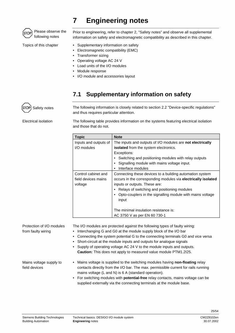
Topic NoteInputs and outputs ofI/O modules
The inputs and outputs of I/O modules are not electricallyisolated from the system electronics.Exceptions:• Switching and positioning modules with relay outputs• Signalling module with mains voltage input.• Interface modules
Control cabinet andfield devices mainsvoltage
Connecting these devices to a building automation systemoccurs in the corresponding modules via electrically isolatedinputs or outputs. These are:• Relays of switching and positioning modules• Opto-couplers in the signalling module with mains voltage
input
The minimal insulation resistance is:AC 3750 V as per EN 60 730-1
The I/O modules are protected against the following types of faulty wiring:• Interchanging G and G0 at the module supply block of the I/O bar• Connecting the system potential G to the connecting terminals G0 and vice versa• Short-circuit at the module inputs and outputs for analogue signals• Supply of operating voltage AC 24 V to the module inputs and outputs.
Caution: This does not apply to measured value module PTM1.2I25.
• Mains voltage is supplied to the switching modules having non-floating relaycontacts directly from the I/O bar. The max. permissible current for rails runningmains voltage (L and N) is 6 A (standard operation).
• For switching modules with potential-free relay contacts, mains voltage can besupplied externally via the connecting terminals at the module base.
Please observe thefollowing notes
Topics of this chapter
Safety notes
Electrical isolation
Protection of I/O modulesfrom faulty wiring
Mains voltage supply tofield devices

26/54
Siemens Building Technologies Technical basics: DESIGO I/O module system CM2Z8102enBuilding Automation Engineering notes 30.07.2002
7.2 Electromagnetic compatibility (EMC)
Please refer to the mounting and installation guide M8102, sections 4.2 "EMCcompliant control cabinet" and 8.2 "Notes on EMC optimisation". These sectionscontain notes and regulations for mechanical engineering of the control cabinet,equipment layout, and EMC-compliant cable wiring.
7.3 Operating voltage AC 24 V
The permissible deviation of AC 24 V nominal voltage at the unit may be +/20 %. Themaximum permissible voltage drop of ±20 % is allocated as follows:1. Mains fluctuations: –10 %2. Supply line between the transformer and the I/O bars: –1.5 %3. Transitional resistance at the I/O bar: –0,5 %4. Connecting cable between the I/O modules and the field devices: –8 %
7.4 Transformer sizing
The transformer output is the sum of the power consumption by the automation station,the I/O modules, and the connected field devices. The "Module functions, data andtypes" table in section 3.2 provides engineering support.
7.5 Load units of the I/O modules
The majority of modules receives its DC 24 V voltage supply from the automationstation via the P-bus.
The load units (1 unit = 12.5 mA) indicate the current supplied to the I/O module by theautomation station.For approximated automation station sizing, the number of I/O points to be connectedmay also be considered.However, the sum of all load units is used for an exact calculation. The load units areavailable in table "Module functions, data and types", section 3.2.
7.6 Module response
After switching on AC 24 V operating voltage or reintroducing a previouslydisconnected module, the module is ready for P-bus access after max. 0.5 s.
The access cycle to a single module is 0.5 s.
The automation station correctly identifies and rejects erroneous data transmissionbetween the I/O modules and the automation station.
EMC optimisation
Tolerance
Transformer output
Defining the load units
Switch-on response
Access cycle
Successful datatransmission

27/54
Siemens Building Technologies Technical basics: DESIGO I/O module system CM2Z8102enBuilding Automation Engineering notes 30.07.2002
The switching and positioning modules' outputs assume a defined status (emergencystatus) if:• Data transmission on the P-bus is interrupted for more than 4 s• The automation station is not supplied AC 24 V operating voltage
As a result:• The relays at the switching modules drop off (except bistable relays)• The following states can be set for positioning modules with modulating outputs:
– The positioning signal moves to zero– The output assumes a predefined value (DC 0....10 V)– The output retains the last known good value
7.7 I/O module and accessories layout
The following criteria apply to the I/O module layout:Grouping of I/O modules to be mounted onto the various I/O bars:• I/O modules whose connections are wired inside the control cabinet (e.g. to
contactors for motor control)• I/O modules whose connections lead to field devices outside the control cabinet
(sensors, transmitters, actuators, etc) The terminal bases of such modulessimultaneously assume the function of control cabinet terminal blocks
Module grouping and allocation to various I/O bars depends on the following:• Number of I/O modules• Standard length of I/O bars• Available space in the control cabinet
The I/O bars can be mounted next to each other and the transition points can be linkedmechanically and electrically by the module supply block. (Do not connect rails L for thephase conductor and N for the neutral conductor).
For application reasons, I/O bars with a common P-bus may be located in separatecontrol cabinets; refer to the wiring example in section 8.3. In this case, observe thegrouping of the I/O modules.
Rule:Module allocation follows the module address sequence wherever possible.On the I/O bars, the sequence of the I/O modules in part follows country-specificregulations and company-internal habits. The primary differentiating criteria andvariants are:• Sequence according to voltage types:
– Mains voltage, max. AC 250 V– Extra-low voltage
• Plant-specific sequence, i.e., following the function flow and the associated controlloops: I/O modules for sensors, transmitters, and actuators are organised for eachplant part.
• Module-type sequence:e.g., signalling modules – measured value modules – counting modules – switchingmodules – positioning modules
Response on errors
Module allocation
Note
Module sequence

28/54
Siemens Building Technologies Technical basics: DESIGO I/O module system CM2Z8102enBuilding Automation Engineering notes 30.07.2002
• Detailed information on module sequence and addressing is available in the differentproject-specific documentation. This information can be generated and printed bymeans of computer-aided engineering workflows and configuration tools (e.g.UNIGYR Design).
• Further information on control cabinet requirements, I/O module and accessorieslayout, control cabinet layout, labelling and addressing is available in the mountingand installation guide "I/O modules and P-bus", M8102.
Additional information

29/54
Siemens Building Technologies Technical basics: DESIGO I/O module system CM2Z8102enBuilding Automation Wiring notes 30.07.2002
8 Wiring notesObserve all wiring information in chapter 8 of the mounting and installation guideM8102, particularly section 8.2 "Notes on EMC optimisation", as well as all regulationsand recommendation noted in this chapter.
• Wiring notes (P-bus and supply)• Connection of field devices to I/O modules
8.1 General wiring information
• Normally wire the devices in the cable ducts.Recommendation: Design the cable duct cross sections for about 30 % reserve.
• Internal and external wiring of devices in the control cabinet can be made togetherwith other lines for mains supply in the same duct such as cables to contactors ortriacs
Use wire types and cross sections as per the following specifications:
Topic SpecificationsCable materials Use regular litz cables and wires. The ends can be connected
directly or strengthened with ferrules or end pins.
Important: If lines with extra-low voltage are run next to lineswith mains voltage, they must show the same insulationproperties as those with mains voltage.
Wire crosssection
The regular wire cross section for internal control lines is 1.5 mm2.
Deviceconnectingterminals at I/Omodules
The device connecting terminals are designed for wires of:• min. 0.5 mm dia.• max. 2 x 1.5 mm2 or 1 x 2.5 mm2
The connecting terminals have metal clamps which make goodelectrical contact and prevent their fastening screws fromdamaging the wire ends.
Connectingterminals for I/Ocompact units
Important: For connecting, use only the inserted, plug-inoriginal connecting terminals.
Please observethe followingnotes
Topics of this chapter
Wire arrangement, ductcross sections
Wires and connectingterminals
30/54
Siemens Building Technologies Technical basics: DESIGO I/O module system CM2Z8102enBuilding Automation Wiring notes 30.07.2002
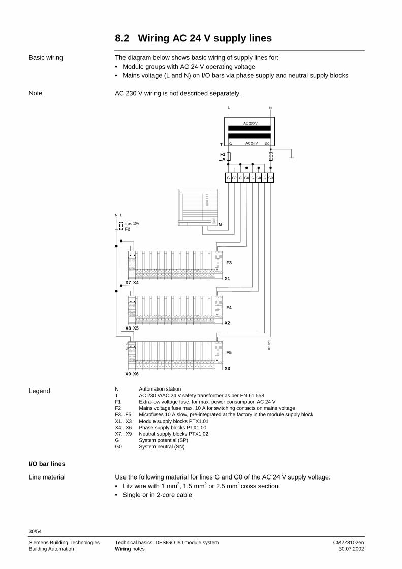
8.2 Wiring AC 24 V supply lines
The diagram below shows basic wiring of supply lines for:• Module groups with AC 24 V operating voltage• Mains voltage (L and N) on I/O bars via phase supply and neutral supply blocks
AC 230 V wiring is not described separately.
AC 230 V
AC 24 V
N
G G0
max. 10A
F2
T
F1...A
G G0 G0 G0 G0G G G
N
F3
X1
X2
F4
X3
F5
L
L
8017
V01
N
X7 X4
X8 X5
X6X9
8017
V01
N Automation stationT AC 230 V/AC 24 V safety transformer as per EN 61 558F1 Extra-low voltage fuse, for max. power consumption AC 24 VF2 Mains voltage fuse max. 10 A for switching contacts on mains voltageF3...F5 Microfuses 10 A slow, pre-integrated at the factory in the module supply blockX1...X3 Module supply blocks PTX1.01X4...X6 Phase supply blocks PTX1.00X7...X9 Neutral supply blocks PTX1.02G System potential (SP)G0 System neutral (SN)
Use the following material for lines G and G0 of the AC 24 V supply voltage:• Litz wire with 1 mm2, 1.5 mm2 or 2.5 mm2 cross section• Single or in 2-core cable
Basic wiring
Note
Legend
I/O bar lines
Line material

31/54
Siemens Building Technologies Technical basics: DESIGO I/O module system CM2Z8102enBuilding Automation Wiring notes 30.07.2002
The following illustration and table show the permissible line lengths to an I/O bar independence of cross section and load.
150
100
50
5 10 15 20 25
P [VA]
L [m]
8102
D10
P [ VA ] 1 mm² 15 mm² 25 mm²
150125
10075
50
25
15
10
1.7 m2
2.53.5
5
10
17
25
2.5 m3
3.75
7.5
15
25
37.5
4.2 m5
6.28.3
12.5
25
42
0
1,5 mm²1 mm² 2,5 mm²
In accordance with the above illustration, the maximum permissible line lengths forvarious wire cross sections at a maximum load (max. 150 VA) each at the I/O bar are:
1.7 m at 1.0 mm2
2.5 m at 1.5 mm2
4.2 m at 2.5 mm2
Do not use cross sections smaller than the designated ones. Do not wire the lines inparallel to increase the cross sections.
These are the rules and recommendations on wiring supply lines:Terminology: The term "system" stands for automation stations together with the
associated I/O module groups.
Topic Rule/RecommendationOwn transformerper system
Recommendation: One transformer per system.Supply of several automation stations and the associatedmodule groups by one shared transformer is permissible if thedevices are mounted in the same control cabinet.
Separate supplylines for AC 24 V
Wire the automation stations and each module groupseparately from the connecting terminal strip (G, G0). Mountthe strip near the transformer (see wiring examples).
Wiring G0 and G tothe I/O bars
Principally wire lines G0 and G to the module supply blocks ofindividual module groups because:• G0 (system neutral) is necessary for module supply• G (system potential) in addition is needed internally for
specific module types, e.g., for manual operation or forsupply of the field devices connected to the module.
Earthing of G0 Connect each system with PELV to the earth at one end only(normally at the transformer) unless otherwise specified.
Load-dependent linelength
Maximum line length
Note
Rules andrecommendations

32/54
Siemens Building Technologies Technical basics: DESIGO I/O module system CM2Z8102enBuilding Automation Wiring notes 30.07.2002
Topic Rule/Recommendation
Connection of G0for distributedsystems
Do not connect the system neutral (G0) of distributed plants.This avoids earthing loops (e.g., by connecting several PCtools).
Separate supply ofautomation stationsand module groups
Within a system, separate supply for automation stations andfor the associated modules groups with one transformer eachis permissible. However:Connect the system neutral (G0) of the two transformers,as G0 serves as the shared return line.
Phase angle of thetransformers
The phase angles of the transformers to each other do notneed to be considered and transformer supply can haveseveral phases ( L1, L2, L3 ).
Separate supply ofthe module groups
This may be meaningful or necessary for:• Widely distributed module groups• High power demand at the I/O bar (actuators)• Modules with AUTOMATIC / HAND switches to ensure
manual operation from emergency supply.
Depending on the situation, further variants can be applied (see wiring examples insection 8.5 of the mounting and installation guide M8102).
The project-specific electrical diagram is binding for control cabinet wiring.
8.3 Wiring sample for AC 24 V supply
See table "Maximum line length" for permissible line length for AC 24 V supply.
AC 230 V
AC 24 V
L N
G G GG0 G0 G0
A1 A2
PTX1.01
N1
X1W1
X2
810
2V0
3
PTX1.01
T1
A1 Control cabinet 1A2 Control cabinet 2N1 Automation stationT1 TransformerW1 P-bus cableX1, X2 I/O module groups
Refer to the mounting and installation guide M8102, section 8.5, for further wiringexamples.
Wiring variants
Binding documentation
I/O modules in separatecontrol cabinets
Legend
Note

33/54
Siemens Building Technologies Technical basics: DESIGO I/O module system CM2Z8102enBuilding Automation Wiring notes 30.07.2002
8.4 P-bus wiring notes
Refer to the mounting and installation guide M8102, chapter 8, for detailed information,rules and notes on loop and star wiring of the standard P-bus as well as usage of theremote P-bus.
Three-core, unscreened round cables inside and outside the control cabinet. Singlewires are not allowed. Flat ribbon cables (with reference line PU as the centre) can beused, but they are more vulnerable to interference.
• Max. 20 m with 3 x 0.75 mm2
• Max. 30 m with 3 x 1.0 mm2
• Max. 50 m with 3 x 1.5 mm2
The information applies to a maximum automation station load of 64 (or 2 x 64) loadunits (LU) and is based on a max. permissible voltage drop of 500 mV on reference linePU. Make sure that you include all individual segments in the overall length.The length of 50 m represents an absolute limit for the standard P-bus based oncable capacity, runtime, and interference radiation.
Run the P-bus cable from the automation station to the module supply block of theclosest I/O bar. Then loop the P-bus cable for all further I/O bars from one modulesupply block to another.
N
X1
X2
X3
W
801
7V1
3
N Automation stationX1...X3 Module supply blocks PTX1.01 of the module groupsW P-bus cable, 3-core
Information on standardand remote P-bus
Standard P-bus:P-bus line
Line lengths and crosssections for the standardP-bus
Wiring procedure
Legend

34/54
Siemens Building Technologies Technical basics: DESIGO I/O module system CM2Z8102enBuilding Automation Wiring notes 30.07.2002
Starlike wiring of the P-bus is permissible, e.g. for several control cabinets in differentlocations, but try to avoid it because of multiple usage of the P-bus terminals on themodule supply block.
If you need to install several automation stations, make sure that the P-bus of therespective automation station is connected only to the associated module groups.Never connect two or several automation station to the same P-bus.You can only set one module supply block for each I/O bar.
8.5 Wiring notes for the remote P-bus
To connect remote I/O module groups to a process bus, the P-bus can be extended to200 m by means of two screened (coaxial) cables.
The remote P-bus is wired using two coaxial cables. Connect the clock (PC) and data(PD) lines to the inner conductor of each coaxial cable. Run the reference voltage (PU)via the screening of the two coaxial cables, whereby the screens of the two cables mustbe linked (see illustration below). In this case, do not ground the cable screening as itis used as the conductor.
PUPD
G0
PC
8102
Z42
PD Data linePC Clock linePU Reference voltage lineG0 System neutral
Refer to data sheet N8022 "Process bus" and the mounting and installation guide "I/Omodules and P-bus" M8102, section 8.7, for detailed information on engineering andwiring.
8.6 Connecting the field devices to the I/O
modules
• The terminal bases of the I/O modules serve as the terminal blocks for connectingexternal units while satisfying all associated standards. As a result, standardseparate control cabinet terminal blocks are not necessary.
• Unswitched mains voltage can be fed via the I/O bar by means of phase supply andneutral supply blocks. The maximum permissible current load of the rails feedingmains voltage is 6 A.
The lines feeding the field can be run unscreened in e.g. cable ducts together withother lines (also supply lines AC 3 x 400V). Any exceptions are available in thetechnical data sheets on the associated devices.
Note
Caution
Application
Wiring
Note
Connection terminals
Line arrangement

35/54
Siemens Building Technologies Technical basics: DESIGO I/O module system CM2Z8102enBuilding Automation Wiring notes 30.07.2002
The line length is restricted by the following criteria:• Line resistance in conjunction with measured value modules for passive resistance
sensors (LG-Ni 1000, Pt 1000)• Voltage drop for measured value modules for active sensors (DC 0...10 V input) and
positioning modules (DC 0...10 V output)• Noise interference from neighbouring lines for all module types
8.7 Wiring signalling and counter value modules
The permissible line length to the signalling contacts and counter value contacts—regardless of the wire cross section (min. 0.6 dia)—is limited to 300 m and defined bythe noise interference that must be expected.
If you need to connect several signalling or counting contacts to separate inputs or tovarious modules, connect the contacts to the same G0 line (system neutral) of an input.This conserves wire.Nevertheless, the associated modules must all be arranged on the same I/O bar!
G0 E1 G0 G0 G0E2 E1 E2
PTM1.2D20
G0 G0E3 E4
PTM1.4D20R
G0 E1
BUS
PTM1.2
8102
A0
2
The number of contacts that you can connect via a shared line G0 depends on theline's length and cross section. The following illustration shows this relationship forcopper lines. For the individual lines to inputs E1...En, the information at the beginningof this section applies.
For modules PTM1.2D20, PTM14D20, PTM18D20, PTM14D20R, PTM12D20S,PTM12C, PTM12QD(M), PTM14QD-M2.
n
60
50
40
30
20
10
050 100 150 200 250 300 L [m]
8102
D05
E
0.5 mm²
1.0 mm²
1.5 mm²
2.5 mm²
0.6 mm dia.
The illustration shows the permissible number of contacts as a function of length andcross section for the shared return line (G0) based on a voltage drop via the sharedreturn line (G0) of max. 1 V (if all contacts E1…En are closed).
Line length and crosssections
Line length
Shared G0 line forseveral contacts
Connection diagram(Example)
Permissible number ofsignalling or countervalue contacts

36/54
Siemens Building Technologies Technical basics: DESIGO I/O module system CM2Z8102enBuilding Automation Wiring notes 30.07.2002
8.8 Wiring measured value modules
8.8.1 Passive resistance sensors and resistance transmitters
With temperature sensors, the temperature is sensed directly via a nickel or platinumwire which changes resistance in relation to the temperature.
8102
D071000 Ω
0°C
R
T
R Sensor signal (resistance)T Temperature actual value (linearised)
The following table shows the resistance for measuring elements LG-Ni 1000, platinum1000 and platinum100 as a function of the temperature.
Temperature Resistance of the measuring element Temperature Resistance
LG-Ni 1000at 0 °C
Pt1000, Pt100at 0 °C (DIN 43760)
Pt1000, Pt100at 0 °C (DIN 43760)
-50 °C 791 Ω (for Pt100 (for Pt100-40 °C 831 Ω values x 0.1) values x 0.1)-30 °C 872 Ω-20 °C 913 Ω 160 °C 1610 Ω-10 °C 956 Ω 170 °C 1648 Ω
0 °C 1000 Ω 1000 Ω 180 °C 1685 Ω10 °C 1045 Ω 1039 Ω 190 °C 1722 Ω20 °C 1091 Ω 1078 Ω 200 °C 1759 Ω30 °C 1138 Ω 1117 Ω 210 °C 1795 Ω40 °C 1186 Ω 1155 Ω 220 °C 1832 Ω50 °C 1235 Ω 1194 Ω 230 °C 1868 Ω60 °C 1285 Ω 1232 Ω 240 °C 1905 Ω70 °C 1337 Ω 1271 Ω 250 °C 1941 Ω80 °C 1390 Ω 1309 Ω 260 °C 1977 Ω90 °C 1444 Ω 1347 Ω 270 °C 2013 Ω
100 °C 1500 Ω 1385 Ω 280 °C 2049 Ω110 °C 1557 Ω 1423 Ω 290 °C 2085 Ω120 °C 1615 Ω 1461 Ω 300 °C 2120 Ω130 °C 1675 Ω 1498 Ω 310 °C 2156 Ω140 °C 1736 Ω 1536 Ω 320 °C 2191 Ω150 °C 1799 Ω 1573 Ω 330 °C 2226 Ω
340 °C 2262 Ω350 °C 2297 Ω360 °C 2332 Ω370 °C 2367 Ω380 °C 2401 Ω390 °C 2436 Ω400 °C 2470 Ω408 °C 2500 Ω
Two-line connection
Measured valuerecording andmeasuring signal
Legend
LG-Ni 1000,platinum 100 /1000

37/54
Siemens Building Technologies Technical basics: DESIGO I/O module system CM2Z8102enBuilding Automation Wiring notes 30.07.2002
The maximum permissible line length for passive resistance sensors and transmittersdepends on the permissible measuring error caused by the line resistance; seeillustrations below.The line length is limited to 300 m. Line lengths exceeding 300 m to the measuredvalue input are possible, but screened cables must be used because of increased noiseinterference.
L
RL
RL
P-BUS
U
B
8102
B01
B Resistance sensor LG-Ni 1000, Pt 1000or resistance transmitter
L Line length (cable length)RL Line resistanceU Measured value module PTM1.2...
One ohm of line resistance is calibrated in the measured value modules andincluded in the following illustrations.
Additionally, sensor calibration can be corrected in terms of software in the automationstation if measuring errors are caused by deviating line resistance or special ambientconditions.
The following illustrations apply to copper lines.
Measured value error of LG-Ni 1000 sensors caused by line resistance.
2
1
0100 200 300
F [K]
L [m]-0.21
1 mm²
1.5 mm²
2.5 mm²
8102
D01
E
0.6 mm dia.
Formula: F =4.7
1A57
L2−
•
•
A Line cross section in mm2
F Temperature measuring error in KelvinL Line length in m
Measuring lines
Legend
Sensor calibration
Measured value errors
Modules PTM1.2R1Kand PTM1.4R1K
Legend

38/54
Siemens Building Technologies Technical basics: DESIGO I/O module system CM2Z8102enBuilding Automation Wiring notes 30.07.2002
Measured value error of Pt 1000 Ω sensors caused by line resistance.
2
1
0100 200 300
1 mm²
F [K]
L [m]
1.5 mm²
2.5 mm²
8102
D02
E
0.6 mm dia.
-0.26
Formula: F =3.9
1A57
L2−
•
•
A Line cross section in mm2
F Temperature measuring error in KelvinL Line length in m
Measured value error of resistance transmitters (potentiometer) caused by line resistance.
2
0-1 100 200 300
1 mm²
L [m]
4
6
8
F [Ohm]
1.5 mm²
2.5 mm²
0.6 mm dia.81
02D
03E
Formula: F =2
571
••
−L
A
A Line cross section in mm2
F Measuring errors in ohms caused by line resistance (2RL for supply and return line)L Line length in m
The measured value error as per the above illustration applies to sensor imaging only,because the LG-Ni 1000 has a non-linear course.
The line length is limited to 300 m. Line lengths exceeding 300 m to the measuredvalue input are possible, but screened cables must be used because of increased noiseinterference.
Module PTM1.2P1K
Legend
Module PTM1.2P1K
Legend
Module PTM1.2R1K
Resistance sensor withfour-wire connection
Module PTM1.2P100

39/54
Siemens Building Technologies Technical basics: DESIGO I/O module system CM2Z8102enBuilding Automation Wiring notes 30.07.2002
8.8.2 Measured value modules with active sensors
Active sensors are connected to modules PTM1.2U10.
The active sensors use a signal amplifier which emits a uniform signal of DC 0...10 V.This voltage range is proportional to the application range of the sensor. A suitablemeasuring system is used to acquire the measured value.Active sensors are available for:• Relative humidity• Pressure in liquid and gaseous media• Pressure difference in liquid media• Pressure difference in gaseous media• Air quality• Air velocity
8102
D08
0 %
U
x100 %
0 V
10 V
U Sensor signal (voltage)x Actual value (0...100% = application range)
The permissible line length for measuring signals of DC 10 V and sensor supplies ofAC 24 V operating voltage are calculated on the following basis for each active sensor(see also the corresponding data sheets for the modules):• Max. 0.5 % measuring error of the measuring range caused by line resistance and• Max. 8 % voltage drop on the AC 24 V supply line to the sensor
• Longer lines are permissible if bigger measuring errors are acceptable• The line length is limited to 300 m. Line lengths exceeding 300 m to the measured
value input are possible, but screened cables must be used because of increasednoise interference.
• If the active sensor is supplied locally via a transformer, the sensor line can be up to300 m with a line cross section of ≥ 0.6 mm dia.
8.9 Switching modules
The line length between switching modules and the equipment to be switched canamount to 1000 m after including the permissible voltage drop.
Fusing is done as per the line cross section and by including the connected consumers.
Connection to moduletype
Measured valuerecording andmeasuring signal
Legend
Supply lines
Note
Line length
Note

40/54
Siemens Building Technologies Technical basics: DESIGO I/O module system CM2Z8102enBuilding Automation Wiring notes 30.07.2002
8.10 Positioning modules
The permissible line lengths between the positioning modules and the modulatingactuators depend on the respective type of actuator and are calculated as follows:• Max. 1% positioning signal error of the positioning range caused by line resistance and• Max. 8 % voltage drop on the AC 24 V operating voltage to the actuator
The line length for DC 0...10 V positioning signals as well as for AC 24 V operatingvoltage is available in the data sheets of the associated modules.
On local supply of the actuators with AC 24 V, the positioning signal line may have alength of up to 300 m at a cross section of ≥ 0.6 mm dia..
Line lengths over 300 m to the measured value input are possible; however, due toincreased humming, screened cables must be used.
The permissible line lengths depend on the power consumption of the actuators usedor the voltage drop between the I/O module and the actuator. The voltage drop islimited to max. 8 %. The illustration below allows for determining the line lengths.
300
200
100
0
10 20 30 P [VA]
L [m]
8102
D09
E
0.6 mm dia.
1 mm² 1.5 mm²2.5 mm²
Formula: F =P
A1313 •
A Line cross section in mm2
L Permissible line length in m (supply and return line)P Power consumption
Modulating outputs
Line length
Note
Three-position outputsfor AC 24 V
Legend

41/54
Siemens Building Technologies Technical basics: DESIGO I/O module system CM2Z8102enBuilding Automation Commissioning notes 30.07.2002
9 Commissioning notesPrior to commissioning, conduct all inspections and checks as per the mounting andinstallation guide M8102, chapter 9.In particular, inspect your installation for faulty wiring that may result in equipmentdamages or bodily injury. In this regard, also refer to the safety regulations in chapter2 of this document.
Installing and de-installing the I/O modules from the I/O bar while under voltage ispermissible.
Emergency operation for I/O modules with manual switch is possible on failure of theautomation station or on bus interruption; however, AC 24 V operating voltage must besupplied to the I/O bar.
Do not use the manual switch on the switching and positioning modules for safetyshutdown, e.g., during service and maintenance procedures.
You can check the functions of the I/O modules at the automation station. Thisprocedure depends on the building automation and control system and is documentedin detail in the associated documentation.
Caution
Installing and de-installingthe modules while undervoltage
Manual switch(emergency operation)
Safety shutdown
Function check

42/54
Siemens Building Technologies Technical basics: DESIGO I/O module system CM2Z8102enBuilding Automation Commissioning notes 30.07.2002

43/54
Siemens Building Technologies Technical basics: DESIGO I/O module system CM2Z8102enBuilding Automation Technical data 30.07.2002
10 Technical data10.1 General data
Operating voltageSafety extra-low voltage SELVor protection by extra-low voltage PELV
AC 24 V +/−20 %
HD384Frequency 50/60 HzI/O module supply via the P-bus DC 24 V (against G0)Permissible load on connecting terminals G, G0 max. 3 A per moduleTerminals for wires of min. 0.6 mm dia. to
2 x 1.5 mm2 or1 x 2.5 mm2
Degree of protection as per EN 60529Module housingTerminal base
IP30IP20
OperationClimatic conditions
TemperatureHumidity
as per IEC 721-3-3class 3K50...50 °C65 % r.h., (85 % r.h., 60 days)
TransportClimatic conditions
TemperatureHumidity
as per IEC 721-3-2class 2K3–25...70 °C75 % r.h., (95 % r.h., 30 days)
Mechanical conditionsOscillation tests
class 2M22 g, as per IEC 68 000-2-6
Product safetyAutomatic electrical controls for householdand similar useSpecial requirements for energy controllers
EN 60 730-1EN 60 730-2-11
Electromagnetic compatibilityImmunityEmissions
EN 61 000-6-2EN 50 081-1
CE conformityElectromagnetic compatibilityLow voltage directive
89/336/EEC73/23/EEC
See the module dimensions Chapter 11, "Appendix"Weight without packaging max. 0.19 kg
Power supply
Connection terminals
Degree of protection ofhousing
Environmental conditions
Standards
DimensionsWeight

44/54
Siemens Building Technologies Technical basics: DESIGO I/O module system CM2Z8102enBuilding Automation Technical data 30.07.2002
10.2 I/O module data
VoltageVoltage for 2D20
CurrentInsulation resistance at open contact
DC approx. 30 VDC 22 V8 mAmin. 50 kΩ
Alternating currentStatus limit level log "1"Status limit level log "0"
DC voltageStatus limit level log "1"Status limit level log "0"
up to AC 30 V effAC ≥ 15 V eff.AC ≤ 5 V eff.up to DC 42 VDC ≥ 7.5 VDC ≤ 2.5 V
Alternating currentStatus limit level log "1"Status limit level log "0"
DC voltageStatus limit level log "1"Status limit level log "0"
Insulation resistanceBetween status inputs and system electronics
up to AC 250 V effAC ≥ 15 V eff.AC ≤ 5 V eff.up to DC 100 VDC ≥ 15 VDC ≤ 5 V
3750 V, as per EN 60730-1
Line length for all signalling modules max. 300 m at 0.6 mm dia.refer to section 8.7
Sensing elementSensor currentMeasuring range
LG-Ni 1000Ω (at 0 °C)2.1...2.7 mA−50...+150 °C
Sensing elementSensing element
Sensor current, constant
Pt100 (DIN IEC 751)Ni100 (DIN 43760)4 mA
Sensing elementSensing element
Sensor current, constantMeasuring range Pt sensorMeasuring range Ni sensor
Pt1000 (DIN IEC 751)Ni1000 (DIN 43760)1.25 mAup to 400 °Cup to 150 °C
Resistance range 0...250 Ω
Resistance range 0...2500 Ω
Input voltagePermissible input voltageInput current
DC 0...10 Vmax. ± DC 20 Vmax. 0.1 mA
Input currentPermissible input voltage
DC 4...20 mADC ± 7 V
Input current (with shunts)VoltagePermissible input voltage
DC 0...25 mADC 0...1 VDC ± 20 V
Contact voltageContact currentImpulse frequency
DC 22 V8 mAmax. 25 Hz
Line lengths for all measured and counter valuemodules
max. 300 m at 0.6 mm dia.refer to section 8.8
Status inputsD20, D20R, D20E, D20Sfor contacts
D42 for voltage
D250 for voltage
Measured value inputsR1K for temperature
P100 for temperature
P1K for resistancetransmitter
P100 for resistancetransmitter
P1K for temperatureU10 for voltage
I420 for current
l25/020 for current
Counter value inputsC for counter valueimpulses

45/54
Siemens Building Technologies Technical basics: DESIGO I/O module system CM2Z8102enBuilding Automation Technical data 30.07.2002
Switching output of the relay contactsAlternating currentPermissible contact current
Min. contact ratingAt mains voltageFor low voltage
Max. switch-on current
AC 24...250 V4 A res., 3 A ind.
AC 230 V / 5 mAAC 24 V / 10 mAAC 10 A (1 s)
Insulation resistanceBetween relay outputs and extra-low voltage element AC 3750 V as per EN 60730-1Line length max. 1,000 m
refer to section 8.9Switching output of the relay contacts
DC voltagePower
DC 19...250 Vmax. 20 W
Switching output of the relay contactsDC voltagePower
DC 19...100 V< 50 V: max. 20 W> 50 V: max. 10 W
Voltage for signalling contactCurrent
DC 22 V8 mA
Output voltageCurrent
DC 0...10 Vmax. 1 mA
Positioning signal, modulatingOutput currentLoad resistance
DC 4...20 mAmax. 500 Ω
Alternating currentPermissible relay contact current
DC voltageSwitching output of the relay contacts
Min. contact ratingAt mains voltageFor low voltage
Max. switch-on current
AC 24...250 V4 A res., 3 A ind.DC 19...250 Vmax. 20 W
AC 230 V / 5 mAAC 24 V / 10 mAAC 10 A (1 s)
Insulation resistanceBetween relay outputs and extra-low voltage element AC 3750 V as per EN 60730-1Line length
Positioning signals, DC 0...10 VPositioning signal three-pos. control output
refer to section 8.10max. 300 m at 0.6 mm dia.max. 1,000 m
Refer to the data sheets of the individual modules for detailed technical data.
Switching outputsAll Q-types
Q250, Q250-M, Q-M3Q250-P(3), Q250A-P
Q250B bistable
QD, QD-MWith signalling input
Positioning outputsY10S, Y10S-M, modulating
Y420 modulating
Y250T, Y250T-M for three-position
All Y-types
Note

46/54
Siemens Building Technologies Technical basics: DESIGO I/O module system CM2Z8102enBuilding Automation Technical data 30.07.2002
10.3 I/O bars
Mains voltage, rails L and NVoltageCurrent
Extra-low voltage, rails G and G0VoltageCurrent
max. AC 250 Vmax. 6 A
AC 24 Vmax. 6 A (150 VA)
MainsExtra-low voltage
max. 10 A10 A slow
PTX1.3PTX1.5PTX1.6PTX1.8* length without end covers in brackets
389 mm (384 mm*)517 mm (512 mm*)645 mm (640 mm*)901 mm (896 mm*)
PTX1.3PTX1.5PTX1.6PTX1.8
0.24 kg0.33 kg0.40 kg0.53 kg
Refer to data sheet N8105 "I/O module system accessories" for detailed informationand technical data on I/O bars, module supply block, phase supply and neutral supplyblock.
10.4 P-bus cable
Round cableBus length incl. all segmentsLine cross section (for 50 m bus length)
3-core, unscreenedmax. 50 m1.5 mm2
2 coaxial cablesBus length incl. all segmentsSurge impedanceCapacity
1-core, e.g. type RG-62 A/Umax. 200 m50...120 Ω< 43 pF/m
Refer to data sheet N8022 for detailed information and technical data on the P-bus.
Load per bar
Back-up fuse(short-circuit protection)Standard length
Weight
Note
Standard P-bus
Remote P-bus
Note

47/54
Siemens Building Technologies Technical basics: DESIGO I/O module system CM2Z8102enBuilding Automation Appendix 30.07.2002
11 AppendixWhat does this chapter contain?• I/O module and I/O bar dimension drawings• Referenced documents• Feedback form
11.1 Dimensions
These are the dimensions for I/O modules PTM1..., snapped onto the following rails:• Top-hat rail EN50022-35 x 7.5 or• G-rail EN50035-G32
87
123
.3
4.5
2x32=64
8106
M01
E
32
40
59.
3
54
EN50035-G32 EN50022-35x7.5 7.5
35
EN50022-35x7.5
80
18
94 94
EN50035-G32
32
15
5
These are the dimensions for the I/O bars PTX1...
18
X x 64 = Y + 4,5
60
8,5
16 32
22,3
4,5
64
8105
M03
The standard length for the I/O bars is a multiple of 64 mm, plus 5.0 mm for both endcovers (PTX1.08):
Type LengthPTX1.3 389 mmPTX1.5 517 mmPTX1.6 645 mmPTX1.8 901 mm
Chapter contents
I/O modules PTM1...
I/O bars PTX1...
Standard length

48/54
Siemens Building Technologies Technical basics: DESIGO I/O module system CM2Z8102enBuilding Automation Appendix 30.07.2002
11.2 Referenced documents
The previous chapters contain all device-specific basic information normally requiredfor engineering the I/O module system.
The following list contains all documents referenced by this document on basics.
Technical documentation by SBT Building Automation• Data sheets (N....) with detailed specifications• Documentation on basics (Z....) for basic information• Mounting and installation guides (M.....) for I/O modules and automation station
The document and classification numbers listed in the table below match those of thedocument information system CONSULT on the company-internal Intranet.
StandardsAll standards applicable to the I/O module system are listed.
Document number(Classification no.)
Title/Description Contents
CM2N8100en(N8100)
DESIGO I/O modulesummary
Overview, functions andselection criteria for the I/Omodules
CM2N8111en toCM2N8179en(N8111 to N8179)
Basic functions and type forthe respective I/O module
Detailed specifications on theindividual modules
CM2Z8102en(Z8102)
Technical basicsDESIGO I/O module system(this document)
Technical basics for definition,engineering, andimplementation of plants, incl.safety regulations
CM2M8102en(M8102)
Mounting and installationguide for DESIGOI/O modules and P-bus
Mounting and installationinstructions
CM2N8105en(N8105)
DESIGO I/O module systemaccessories
Description of the accessoriesrequired for mounting andlabelling
CM2N8663en toCM2N8666en(N8663 to N8666)
Interface function and typefor the associated interfacemodule
Detailed specifications on theindividual modules
CM2N8022en(N8022)
P-bus (process bus) Application, engineering, andinstallation notes, technicaldata
CA1M9202en(M9202)
Mounting and installationguide on DESIGO PX
Mounting and installationinstructions
CM2M8202E(M8202)
Mounting and installationguide on UNIGYR processunits
Mounting and installationinstructions
CM2M8017E(M8017)
Mounting and installationguide on VISONIK BPS
Mounting and installationinstructions
Documents and standards
Note
Technicaldocumentation
I/O modules
Interface modules
P-bus
DESIGO PX(automation stations)
UNIGYR process units
VISONIK-BPS

49/54
Siemens Building Technologies Technical basics: DESIGO I/O module system CM2Z8102enBuilding Automation Appendix 30.07.2002
Document number(Classification no.)
Title Contents
Online help DESIGO PX application Description of functions
CM2Z8281E2(Z8281)
UNIGYR: Manual of functionsI/O blocks
Basic data on I/O blocks
CM2T8567E(T8567)
VISONIK System Basics Basic and functionaldescriptions
HD 384 Electrical installations in buildingsEN 61 558 Safety of transformers, power supply units and similar
equipmentEN 60 730 Automatic electrical controls for household and similar use
DESIGO PX system
UNIGYR system
VISONIK system
Standards

50/54
Siemens Building Technologies Technical basics: DESIGO I/O module system CM2Z8102enBuilding Automation Appendix 30.07.2002

51/54
Siemens Building Technologies Technical basics: DESIGO I/O module system CM2Z8102enBuilding Automation Feedback-Formular 30.07.2002
Feedback formPlease give us your opinion of this document and help us improve it. Thank you!
Evaluation: 1 = always true, 2 = partially true, 3 = not truePlease cross as applicable.
Please tell us who you are:
Last name: .......................................First name: .......................................Company: .........................................Department: ......................................Function: ...........................................
Address: .......................................................................................................................................
Country: .............................................................Tel./Fax:.............................................................E-mail: ..............................................................
1. I am familiar with the product described: 1 2 32. I use this manual for:
Operation Engineering Reference Assembly Introduction Installation Basics Commissioning Problem solving Service New functions ..........................................................
3. How do you locate information in this manual? Table of contents Index
Paging ..........................................................
I could not find: .......................................................................................................
4. I use the following from this manual: Workflows Function descriptions Background information Technical data Detailed information Safety notes Tips and tricks Troubleshooting The following is missing: .........................................................................................
.................................................................................................................................5. The level of technical detail meets my requirements: 1 2 3
Example (page....): ...........................................................................................................6. I find the information I need within an appropriate time: 1 2 3
Example (page....): ...........................................................................................................7. Text/graphics/tables are easy to understand: 1 2 3
Example (page....): ...........................................................................................................Mistakes (page....): .......................................................................................................................................................................................................................................................
8. I particularly like: ..........................................................................................................................................................................................................................................................
9. I particularly dislike: ......................................................................................................................................................................................................................................................
10. The overall impression (structure, layout) is attractive: 1 2 311. May we contact you directly? Yes No
------------------------------------------------------------------------------------------------------------------------------------------------------------------------------------------------------------------------------------

52/54
Siemens Building Technologies Technical basics: DESIGO I/O module system CM2Z8102enBuilding Automation Feedback-Formular 30.07.2002
Please return the completed form to the following address:
Siemens Building Technologies AGBuilding AutomationTechnical Documentation (5655)Gubelstrasse 22CH-6301 Zug
Tel.: +41 41–724 5655Fax: +41 41–724 5686
----------------------------------------------------------------------------------------------------------------------------------------------------------------------------------------------

53/54
Siemens Building Technologies Technical basics: DESIGO I/O module system CM2Z8102enBuilding Automation 30.07.2002

54/54
Siemens Building Technologies Technical basics: DESIGO I/O module system CM2Z8102enBuilding Automation 30.07.2002
Siemens Building Technologies Ltd.Building AutomationGubelstrasse 22CH-6301 ZugTel. +41 41-724 24 24Fax +41 41-724 35 22www.landisstaefa.com
© 2000 Siemens Building Technologies Ltd.Subject to change