detail estimating pipe culverts - ontario · appendix b – additional pipe culvert design factors...
TRANSCRIPT
DETAIL ESTIMATING PIPE CULVERTS
B421-2 – PIPE CULVERTS – OPSS 421 421.1 GENERAL
Pipe culverts are installations designed to provide for the conveyance of surface water, pedestrians or livestock using preformed or pre-cast pipe sections, circular or non-circular in cross-section, laid end to end using suitable joint materials. Good design practice requires a multi-disciplinary approach with full consideration of the multiple purposes of the pipe culvert. Following are some of these considerations: conveyance of flow without creating adverse drainage impacts elsewhere; maintenance of fish passage and protection of fish habitat upstream and downstream of the pipe culvert; maintenance of natural stream patterns; and addition of aesthetic value to the right-of-way. Some pipe culvert structures or underpasses are designed for pedestrian and livestock use, either exclusively or combined with drainage. Where a new pipe culvert is to be placed in flood plain lands and/or in environmentally sensitive streams, the Department of Fisheries and Oceans, or Ministry of Natural Resources, or the local conservation authority should be consulted. All design assumptions and calculations required to design a pipe culvert shall be retained as part of the design documentation.
421.2 REFERENCES MTO Drainage Management Manual MTO Gravity Pipe Design Guidelines Ontario Provincial Standards Specifications Ontario Provincial Standards Drawings Drainage Guidelines available on the MTO public web site All references noted are available through the Contract Preparation System (CPS) or through the ministry’s public web site or through the MTO Online Catalogue library. The designer shall also reference other design manuals (i.e. MTO Roadside Safety Manual) as required for design assistance of other roadside features associated with the pipe culvert design.
September 2011 Page 1 of 36 B421-2

DETAIL ESTIMATING PIPE CULVERTS
421.3 TENDER ITEMS Pipe Culvert Non-Circular Pipe Culvert Pipe Culvert Extension Non-Circular Pipe Culvert Extension Concrete Appurtenances Clay Seal
421.4 SPECIFICATIONS
The requirements for the pipe culvert, non-circular pipe culvert, pipe culvert extension, non-circular pipe culvert extension and concrete appurtenance tender items are contained in OPSS 421. Trenching, backfilling and compaction requirements are specified in OPSS 401 while rock excavation requirements are specified in OPSS 403. The designer shall also reference or note other OPSS documents for construction and materials as identified or required when packaging a contract.
421.5 APPENDICES Appendix A – Pipe Culvert Tender Item - This appendix describes the pipe culvert tender item and is to be followed by the designer to itemize the pipe culvert tender item entries, complete with all pipe material specifications, in the Quantity – Pipe Culvert sheets for all ministry contracts. It also illustrates an example of how to interpret and create the pipe culvert tender code. Appendix B – Additional Pipe Culvert Design Factors - This appendix describes the components in pipe culvert designs and is to be used by the designer to accurately identify the pipe culvert installation work in the Quantity – Pipe Culvert or other quantity sheets for all ministry contracts, as appropriate. Appendix C - CPS Master List of Pipe Culvert Tender Items - This appendix provides a list of all pipe culvert tender items for circular and non-circular pipes available for selection and a and a brief example of how a pipe is selected from the tender item list.
421.6 SPECIAL PROVISIONS Refer to Chapter 'E' to review standard special provisions that may be required for inclusion in the contract.
September 2011 Page 2 of 36 B421-2
DETAIL ESTIMATING PIPE CULVERTS
421.7 STANDARD DRAWINGS Applicable standard drawings are contained in the 800 series of the Ontario Provincial Standard Drawings Manual; however, other OPSD or MTOD series may also apply.
421.8 DESIGN 421.8.1 Pipe Culvert
Prior to detailed design, the designer shall verify whether there are significant concerns regarding fish migration/passage or habitat, flooding, adverse drainage impacts, erosion, etc. and determine the criteria and/or standards to which the pipe culvert will be designed. The general alignment, size, type and class of a pipe culvert are established, based on acceptable drainage theory, by the designer. The designer shall use accepted drainage design methods by which to establish the pipe culvert design that satisfies required drainage standards or criteria for the highway project. The design of pipe culvert grades and the setting of upstream invert elevations require the consideration of several factors. These factors are discussed in the MTO Drainage Management Manual. As a general rule, pipe culverts other than entrance pipe culverts should be placed to a depth equal to one tenth of the height or diameter of the pipe culvert below the bottom of ditch, unless there are reasons for deviating from this rule. Complete design requirements, analysis methods and other information are available in the MTO Drainage Management Manual. A. Size The design of a pipe culvert involves determining the size of a pipe that will permit the pipe culvert to function within set design requirements and standards. The designer will determine the maximum increase in pipe culvert size that will still permit the pipe culvert to function within the design parameters set. For crossings where multiple pipe culverts are required, refer to Appendix B – Additional Pipe Culvert Design Factors for additional information on how to determine spacing and other requirements. B. Type Pipe type refers to a pipe’s inner wall design, which can be smooth or corrugated.
September 2011 Page 3 of 36 B421-2

DETAIL ESTIMATING PIPE CULVERTS
The designer will use hydraulic flow parameters characteristic of the pipe under analysis during the design of the pipe culvert. The initial pipe culvert size shall be assessed based on one pipe type. If the pipe culvert was designed based on smooth pipe parameters, the designer shall determine if a corrugated pipe, complete with maximum size tolerances, for the same alignment can be installed and also maintain the functionality of the pipe culvert within the design parameters set. In some cases, a hydraulically acceptable corrugated pipe culvert may not be achievable or conducive to site conditions. The same is true for the reverse case if the original design was based on corrugated pipe parameters. The designer must specifically undertake an analysis of a pipe culvert designed with both pipe types if both types are to be specified in a contract as a mix and match option. Otherwise, the pipe culvert design shall be designed as one pipe type throughout. Circular or non-circular pipe culverts greater than 3000 mm in diameter or span are classified as structures and are designed from first principles in conjunction with structural engineers following the requirements of the Canadian Highway Bridge Design Code and the MTO Structural manual. C. Class Pipe class refers to the material specifications of the pipe products. These specifications include load and pressure ratings, pipe wall thickness, protective coatings, corrugations and reinforcement. Acceptable material specifications of a pipe culvert is established, based on structural loading and material durability requirements, by the designer. The designer shall use accepted structural and durability assessment methods by which to establish the pipe class that satisfies both structural and material durability criteria.
1. Structural Assessment Pipe culverts, due to the fact that they are installed underground, are subject to ‘dead’ and ‘live’ loads. The designer, based on the pipe’s ability to carry loads, shall specify pipe of suitable material properties for the pipe culvert. The depth to pipe refers to the depth of material that will be placed on top of the pipe culvert. The depth of material includes bedding, cover, embedment in the case of flexible pipes, backfill, subgrade, and pavement material above the pipe. The total depth of material shall be sufficient to satisfy minimum or maximum heights of fill necessary for load support and the frost depth requirements for all acceptable pipe sizes, types and classes specified upon pipe culvert design completion. The final pipe materials for the pipe culvert installation shall be such that the
September 2011 Page 4 of 36 B421-2

DETAIL ESTIMATING PIPE CULVERTS
structural requirements in addition to material durability requirements have been met or exceeded. The designer shall also refer to the OPS Height of Fill tables for further information on pipe material load ratings to satisfy structural loading requirements. 2. Durability Assessment Pipe culverts, for the different functional highway classifications, must be designed to specified Design Service Life (DSL) criteria. The water and soil environment into which the pipe material will be installed has an impact on the pipe material’s service life. Every pipe material considered will have an Estimated Material Service Life (EMSL) based on its material properties and the site environment. Pipe materials shall be specified by the designer based on the pipe material’s ability to provide an EMSL greater than or equal to the DSL of the pipe culvert installation on the highway project. The designer may consider pipe materials with an EMSL less than the DSL required, provided that the design of the pipe culvert incorporates appropriately timed pipe culvert replacement(s) during the DSL time span and that the Life Cycle Cost Analysis (LCCA) has demonstrated these pipe materials are a viable option for consideration. The final pipe materials that are acceptable for the pipe culvert installations shall be such that pipe material durability requirements in addition to structural requirements have been met or exceeded. Pipe sizes, types or classes that cannot satisfy the DSL requirements at the site shall not be included in the pipe culvert tender item unless a pipe replacement option has been determined to be acceptable. The designer shall also refer to the MTO Gravity Pipe Design Guidelines for further information on pipe material selection, setting highway DSL criteria and water/soil testing requirements.
D. Joints The designer, through subsurface information as provided in a foundations or geotechnical report, shall make an assessment of the type of pipe joints required for the pipe culvert. If the groundwater table may extend above the pipe culvert invert for long periods of time or if there are potential backwater conditions, it may be necessary to specify pipe joints that address infiltration and/or exfiltration. Prevention of these actions by water flow ensures that the bedding, cover or embedment materials around the pipe culvert remain in place and provides a stable fill environment for the pipe culvert installation.
September 2011 Page 5 of 36 B421-2
DETAIL ESTIMATING PIPE CULVERTS
Sealed types of joints include gaskets or other types of seals or the pipes can be welded together enabling a “sealed” joint that minimizes or prevents the movement of water and soil fines through the joint. The sealed joints can be selected as either high or low pressure joints depending on the type of seal that will be required for the pipe culvert under design. A “non-sealed” joint can be specified if water or soil fines movement through the joint is practically non-existent or is not a significant concern. Geotextile may also be used on pipe joints to prevent migration of bedding, cover or embedment fines into the pipe culvert and being removed from the pipe culvert location. The designer shall also refer to the MTO Gravity Pipe Design Guidelines for further information on pipe joint selection requirements. E. End Finish and Safety The use of bevels or end finishes on a pipe culvert is to be decided by the designer through hydraulic analysis. When corrugated steel pipe is used for a pipe culvert, the protruding end may be cut to more aesthetically blend with the surrounding slopes. Where traffic safety is an issue, the designer may also consider a safety end treatment on the pipe culvert ends. The designer shall refer to relevant design manuals and any associated OPSD’s for further information on warrants and design of safety end treatment. F. Treatment Flow sources carrying sediment loads under certain velocity conditions may require paving the pipe culvert invert to prevent abrasion of the pipe material. Bituminous products shall not be used to pave the invert of the pipe culvert. In lieu of a paved invert, the designer may also consider pipe products with thicker walls and/or protective coatings to provide additional protection against abrasive forces. Fish bearing streams may require channel substrate or baffles to provide suitable conditions for fish to travel through the pipe culvert. Substrate placement mimics the conditions of the streambed throughout the culvert barrel(s) to provide continuity of the stream environment to the fish. The pipe culvert size may need to be increased to properly embed the pipe culvert and provide suitable substrate depth in which to form the low flow channel for fish passage. Baffles are used when channel velocities are sufficiently high enough that necessitate the need to provide fish with resting zones during their migration upstream. Once again the pipe culvert size may need to be increased to accommodate baffle block
September 2011 Page 6 of 36 B421-2
DETAIL ESTIMATING PIPE CULVERTS
heights and suitable resting zone water depths and lengths. The size increase may also be required to accommodate capacity requirements for larger flow events. The designer shall also refer to the MTO Management Manual for further information on design of low flow channels and baffles. G. Concrete Appurtenances The flow through a pipe culvert may need to be controlled to prevent erosion damage to the area around it or to the pipe structure itself. Concrete appurtenances such as headwalls, wingwalls, energy dissipators, aprons, collars or other such types of structures are used to direct flow, slow velocities to prevent erosion, offset buoyancy forces, etc. Concrete structures covered by OPSS 904 do not include the aforementioned concrete appurtenances.
421.8.2 Trench A. Excavation Excavated earth material may be used for embankment construction or used as native backfill to the excavated pipe culvert trench as determined by the designer based on foundation or geotechnical reports. Surplus or unsuitable excavation material should be managed as outlined in B206 of this manual. In view of the high unit cost of rock excavation, the designer shall endeavour to reduce the volume of excavation by relocating, pipe skewing, etc., wherever possible. Excavation in rock for placing pipe culverts is also done according to OPS Drawings. Special treatment of pipe culverts may be required for frost protection. Frost treatment is required if the frostline falls below the top of the pipe culvert, within the bedding layer or below the bedding layer. Foundations or geotechnical reports shall contain information regarding recommended pipe fill materials and the configuration and extent of frost taper excavations. Frost tapers are not required when the frostline falls above the pipe culvert. In rock fills, frost tapers are not required, but fill material must be provided. Pipe culverts being placed on sideroads that are paved or will be paved, either under the current project or in the foreseeable future, must be provided with frost tapers, where required, regardless of the length of paving (pipe culvert within the limits of paving or future paving). Information on future sideroad requirements should be obtained from municipalities. On gravel roads, pipe culverts should not be provided with frost tapers unless specifically identified in a foundations or geotechnical report or requested by the municipality.
September 2011 Page 7 of 36 B421-2
DETAIL ESTIMATING PIPE CULVERTS
B. Tunnelling, Jacking and Boring Pipe Culverts In addition to the usual open-cut method of installing pipes, there are three other methods employed where trenching is not practical:
a) Tunnelling; b) Jacking and boring; and c) Pipe lining (non-standard special provisions are required) Details of these methods of installation are discussed in Sections B415 and B416 of this manual. C. Dewatering or Unwatering Dewatering refers to pumping, baling, temporary ditching or vacuum removal of uncontaminated groundwater, rain water, melt water, surface runoff, water pipe leakage from excavations and trenches or within sheeted coffer dams to improve the soil stability or for other construction purposes. Unwatering refers to the lowering of the groundwater table in the excavation site area in a manner that enables completion of the construction work. Where dewatering is required for the installation of a pipe culvert, the details shall comply with the requirements of OPSS 517. Where unwatering is required, the details shall comply with OPSS 902. Although the Contractor is responsible for a dewatering or unwatering plan, the designer shall note any recommendations included in the foundation investigation and design report. The designer shall also refer to SP100S59, Amendment to MTO General Conditions of Contract, Permits to Take Water, for additional requirements that may need to be specified in the contract. D. Fill Material To prevent damage to the pipe culvert due to “live” and “dead” loads, pipe fill material is provided as protective and support layers. Pipe fill material for rigid pipe installations is placed in distinct bedding, cover and backfill layers. Flexible pipe installations require pipe fill material to be placed as distinct embedment, which is from the bottom of the bedding layer to the bottom of the backfill layer, and backfill layers. The minimum or maximum height of pipe fill material is placed in accordance with OPSD Height of Fill tables for the pipe materials identified. The minimum depth of cover for entrance pipes is 300 mm. In rock cuts, this may require lowering of the ditch grade, using pipe arches or excavating the shatter below the ditch bottom.
September 2011 Page 8 of 36 B421-2
DETAIL ESTIMATING PIPE CULVERTS
A foundation or geotechnical report will include recommendations for the supply, placement, and specifications of pipe fill material or any special conditions for bedding, cover, embedment in the case of flexible pipes and backfill layers. In addition, special consideration for scour protection at the pipe culvert inlet or outlet may be required and the designer shall refer to the MTO Drainage Management Manual for assistance. The designer shall, based on the recommendations of the foundation or geotechnical report, specify the pipe fill materials required for the installation. The designer should be familiar with the various installation methods available as referenced in the 800 series of the OPSD for the pipe culvert installation so that the pipe fill materials recommended are appropriately specified. The contractor, not the designer, is responsible for selecting the appropriate pipe culvert installation method at the time of installation based on the soil types found on the construction site in accordance with the Occupational Health and Safety Act and Regulations for Construction Projects. E. Reinstatement Where existing driving lanes must be excavated to allow the construction of the pipe culvert crossing, the affected roadbed must be rebuilt to acceptable standards to maintain the continuity of the pavement. This is particularly important where there is to be no resurfacing of the highway. The designer shall determine and specify bedding, cover and backfill depths and materials up to subgrade. Above subgrade, the designer shall determine the types and depths of granular and pavement courses necessary to achieve roadbed integrity. F. Protection Systems These systems will be applicable where the stability, safety or function of an existing roadway, railway, etc. may be threatened or impaired due to the construction of a pipe culvert or in cases where the pipe culvert will be installed at a depth where protection schemes are required. When pipe culverts are to be placed in deep installations or in areas of rock excavation or where an exceptionally large and complex culvert layout is to be constructed, the designer shall request that soils borings be taken along the actual pipe culvert alignment for more precise data. The foregoing is also relevant to the selection of backfill materials and procedures. The design, installation, monitoring of protection systems is the Contractor’s responsibility and the Contractor should base his plan on information as found in foundation or geotechnical reports. Problematic soils, high groundwater tables or other installation issues, if identified, will give rise to recommendations regarding the
September 2011 Page 9 of 36 B421-2
DETAIL ESTIMATING PIPE CULVERTS
design, installation and removal and would also be provided in these reports. Recommendations for performance levels can also be found in foundation investigation and design reports. Requirements for field investigation, laboratory testing and engineering recommendations for protection systems are to be specified in the foundation engineering terms of reference for any specific project such that appropriate information for the Contractor is provided. G. Clay Seals
Warrants for clay seals to be installed on pipe culverts may include:
a) The natural sub-base and pipe culvert foundation materials are of a granular
nature; b) The embankment material is of a non-cohesive nature; or c) There is significant hydraulic head differential between the upstream and
downstream ends of the pipe culvert. Recommendations are found in a foundation or geotechnical investigation and design report. H. Camber A foundations or geotechnical report will contain information and design requirements for the camber depths needed for flexible pipe installations. Also refer to Appendix B – Additional Pipe Culvert Design Factors for additional information on how to determine the amount of camber depth is required.
421.9 COMPUTATION 421.9.1 Item Payment Basis
Pipe Culvert items are Plan Quantity Payment items. Non-Circular Pipe Culvert items are Plan Quantity Payment items. Pipe Culvert Extension items are Plan Quantity Payment items. Non-Circular Pipe Culvert Extension items are Plan Quantity Payment items. Concrete Appurtenances are Plan Quantity Payment items. Rock Excavation for Trenches and Associated Structures is a Plan Quantity Payment item. Clay Seal is a Lump Sum item.
421.9.2 Sources of Information
September 2011 Page 10 of 36 B421-2

DETAIL ESTIMATING PIPE CULVERTS
The main sources of information for pipe culvert items are: a) Survey notes and plans that provide profiles along the drainage course at both
existing and new pipe culvert locations and drainage courses in addition to drainage areas, mosaic studies, soil types, etc, that provide information to assist in the calculation of pipe culvert sizes.
b) MTO Drainage Management Manual provides the overall guidance on the design
of pipe culverts and other storm drainage systems. c) MTO Gravity Pipe Design Guidelines provide DSL criteria, water chemistry
testing and pipe material selection procedures and requirements. d) Foundation or geotechnical reports provide guidance and recommendations on
subsurface and groundwater conditions, backfilling requirements, special foundation treatments, camber, articulation, scour protection at the culvert inlets/outlets and the need for placing clay seals. The foundation or geotechnical reports should also provide recommendations regarding dewatering or unwatering requirements.
421.9.3 Methods of Calculation
The unit of measurement for circular and non-circular pipe culverts is the metre. The price per metre for placing pipe culverts includes the following operations: a) Supplying, placing and joining pipe lengths; b) Earth excavations for trenches, frost tapers, etc. for pipes, end treatments and
concrete appurtenances; c) Supplying, placing and compacting all bedding, cover, embedment in the case of
flexible pipes and backfill materials for pipe culverts; d) Dewatering or unwatering operations, unless otherwise specified; e) Design, installation and removal of protection systems; f) Reinstating or constructing any highway attributes, not covered under other g) required works in the contract, as part of the pipe culvert installation; and h) Disposing of all surplus excavated materials.
421.9.4 Pipe Culvert
September 2011 Page 11 of 36 B421-2
DETAIL ESTIMATING PIPE CULVERTS
A. Length The design length (L) of pipe culverts is the distance between the toes of embankment slopes where they meet the streambed profile measured to the nearest full metre. When the space is restricted or short lengths are required, the metric design length of pipe culverts may be determined as the next larger 0.1 metre. Where pipe culvert end- treatments are used, the length of the pipe culvert is the distance between the intersections of the embankment side slopes and the top of the pipe culvert, measured to the nearest full metre, with the lengths of the two end treatments added. While the standard rock slope is 1¼:1, the length of pipe culvert should be based on a rock slope of 1½:1. Generally pipe culverts, in particular entrance pipe culverts, are designed longer than is necessary. Extra care should be taken where an entrance or sideroad pipe culvert is located within the radius area to ensure that the pipe culvert is not designed longer than necessary. Slope flattening should also be considered when calculating the length of pipe culverts. The length of a pipe culvert is measured horizontally, except when the pipe grade is 10% or steeper, in which case the length is measured along the slope. B. Joints Pipe joints are inclusive with the work to be done when installing a pipe culvert. C. Concrete Appurtenances The unit of measurement for concrete appurtenances is the cubic metre. The volume of each structure is computed and the payment in cubic metre covers the cost of supplying and placing both concrete and reinforcing steel. Payment for excavation and backfilling, including the supply of granular material, is included with the associated pipe culvert tender item.
421.9.5 Trench
A. Excavation Earth excavation required to place pipe culverts is part of the cost for placing the pipe culvert. Excavation in earth for placing pipe culverts is done according to OPS Drawings. Unlike earth excavation, rock excavation is tendered as a separate item. The main sources of information for the computation of the tender item " Rock Excavation for Trenches and Associated Structures " are the foundations or geotechnical reports and
September 2011 Page 12 of 36 B421-2

DETAIL ESTIMATING PIPE CULVERTS
soils profile and field survey notes. The unit of measurement for this tender item is the cubic metre. Usually, the field survey drainage information contains a profile along the centreline of the pipe culvert, which is used to compute both pipe culvert length and volume of excavation. When the only information available is a profile along the centreline of the pipe culvert, the excavation is computed as shown in Figure B421-4, which can be found in Appendix B. However, when cross-sections are taken normal to the axis of the projected pipe culvert location, a more accurate computation of the quantity of excavation is obtained. Where a pipe culvert is installed in a rock cut, the volume of excavation is measured from the top of the shatter. B. Swamp Excavations In swamp areas where existing embankments are being widened, excavate existing embankment and swamp as per the appropriate Ontario Provincial Standard drawings, and apply quantities to Earth Excavation (Grading) or Rental of Swamp Excavation Equipment. C. Dewatering or Unwatering Dewatering operations are according to OPSS 517 while unwatering operations are according to OPSS 902. The designer shall ensure the requirements of SSP 100S59 are accounted for. Should a rare situation occur where it would be unfair to the Contractor to include an expensive dewatering or unwatering operation in his pipe bid price, then consideration could be given to using a separate tender item. D. Fill Material Granular volumes for frost tapers, bedding, cover, embedment in the case of flexible pipes and backfill material for pipe culverts are computed as shown in Ontario Provincial Standard Drawings or from detail drawings when applicable. Granular materials for concrete appurtenances are included in the pipe culvert granular quantities. The total granular requirement for each pipe culvert location is computed in cubic metres, and may be converted to tonnes using the conversion factor shown in B314 “Granulars” of this manual. This quantity is used for Geotechnical ASL purposes only.
September 2011 Page 13 of 36 B421-2

DETAIL ESTIMATING PIPE CULVERTS
E. Clay Seal The unit of measurement for this tender item is lump sum, which covers excavation and the supply and placement of all materials to provide an effective seal. No volume calculations for clay seals are needed.
421.10 DOCUMENTATION 421.10.1 Drawings
A. Pipe Culvert
1. Location New pipe culverts, and existing pipe culverts requiring extensions or end-sections, are shown on the plans and profiles of the contract drawings, numbered sequentially in the direction of chainage. Pipe culverts to be removed are not numbered, however details regarding elevation and length of existing pipe culverts are shown crossed out on the drawings. 2. End Finish The applicable drawing for such end finishes are shown in the Ontario Provincial Standard Drawings. The types of safety end treatments are listed in the CPS Master Item list and will be listed as separate tender item in a column on the Quantities – Pipe Culverts sheets. 3. Concrete Appurtenances Concrete Appurtenances are identified on the contract plans by means of an arrowed note (e.g. - Concrete Collar), and specifying the OPS Drawing No., or a special drawing, if required, showing the layout. 4. Treatment Typical cross section drawings must be included in the contract drawings giving dimensions and shape of channel substrate materials or fish baffles. Locations of baffles must be shown on a typical profile drawing.
B. Trench
September 2011 Page 14 of 36 B421-2
DETAIL ESTIMATING PIPE CULVERTS
1. Fill Material Ontario Provincial Standard Drawings depict dimensions, classes or types of bedding requirements for circular and non-circular pipes, of which the pipe can be either flexible or rigid. Typical cross-sections must be included in the contract drawings, giving dimensions of frost depth, slope of tapers and depth of fill material layers. Because of the variety of possible treatments, standard drawings are not considered appropriate. If special conditions for bedding, cover, embedment, in the case of flexible pipes, or backfill materials are required, the appropriate dimensions must be shown on applicable Ontario Provincial Standard Drawings or on detail drawings when applicable. 2. Reinstatement A typical section, traditionally known as "trench reinstatement," must be shown on the contract plans. The drawing should refer to the applicable standard drawings for bedding and backfill up to subgrade. Above subgrade, the drawing should specify the types and depths of granular and pavement courses necessary to achieve roadbed integrity. If no highway pavement resurfacing is to take place in the area of the reinstatement, all reinstatement works should be noted for the contractor to include in his pipe culvert tender item bid. 3. Special Foundation Treatment A detailed typical drawing and/or a modified OPSD will be necessary to show the depth of bedding and location if any special foundation treatment such as cambering, articulation, soil mixing, ground improvement, etc is included in the foundation investigation and design report. 4. Protection Systems When protection systems are required, the line of protection or a protection system shall be shown on the contract drawings. Performance levels shall be included on the Contract Drawings. These are only approximate lengths or locations and it is up to the contractor to design, install and remove with actual lengths and locations defined. 5. Clay Seal
September 2011 Page 15 of 36 B421-2
DETAIL ESTIMATING PIPE CULVERTS
A detailed dimensioned sketch must be shown on the contract drawings for each location, based on information from foundations or geotechnical report.
421.10.2 Documents 421.10.2.1 Quantities Sheet
The "Quantities - Pipe Culverts" sheet shall show details such as: 1. Culvert Number: numerical identifier of pipe culverts in the contract. 2. Station: chainage station on the contract. 3. Location: offset position from C/L of highway. 4. Extension: identifies placement of pipe culvert extensions by entering the length
of the extension into the appropriate right or left extension column, or both columns if there will be an extension on both ends of the pipe culvert, of the “Quantities – Pipe Culverts” sheet. Facing the direction of increasing chainage identifies the right and left side of the pipe culvert. The total length of the extension or extensions, if both left and right ends of the pipe culvert are receiving an extension, is entered into the appropriate Pipe Culvert Extension tender item column of the “Quantities – Pipe Culverts” sheet (refer to #12 below for details of how to enter the pipe culvert extension tender item). Different sizes of circular or non-circular pipe culvert extension will necessitate entry of separate tender items.
5. Skew number: Refer to Appendix B – Pipe Culvert Design Factors for
information on how to determine skew number. 6. End Finish: type of end finish to be applied to the pipe culvert which can be
“SqE” for square end, “B” for bevel end, “Sk” for skew end, “SB” for step bevel and “ES” for steel end section. Refer to Appendix B – Pipe Culvert Design Factors for information on how to select end treatment options for pipe culverts.
7. Depth to Pipe: from the top of the road surface measured at C/L of highway down
to top of base pipe opening directly under the C/L. 8. Pipe Fill Material: Where there are no recommendations from a foundations or
geotechnical report to specify any particular pipe fill material, the pipe fill materials will be specified, by default, as “G” for bedding and by extension embedment, and “N” for backfill and cover. The designer does not have to enter any material specifications in the columns to have the default material specifications apply.
However, specific pipe fill material for bedding, cover or backfill, if
September 2011 Page 16 of 36 B421-2
DETAIL ESTIMATING PIPE CULVERTS
recommended in a foundations or geotechnical report, shall be specified in the appropriate pipe fill material column. Pipe fill materials shall be specified as follows:
• N – native material, which applies to cover and backfill material only and also
permits Granular B Type I, II or III, or Granular A to be used; • G – only Granular B Type I, II or III, or Granular A may be used; • B – only Granular B Type II or Granular A may be used; • A – only Granular A may be used; and • C – Unshrinkable Fill (Concrete).
A single letter code is used to indicate that the same pipe fill material for a pipe
fill layer if it is suitable for both rigid and flexible pipe options. Two letter codes are structured such that the first letter specifies the pipe fill material for rigid pipes while the second letter specifies the pipe fill material for flexible pipes for a pipe fill layer.
Embedment for flexible pipes is from the bottom of bedding layer to bottom of
backfill layer and is specified in the bedding material column. When flexible pipes are only specified, the pipe fill material cover column is not applicable to pipe fill material specifications.
9. Pipe Joints: Types are to be specified in the appropriately labeled column on the
"Quantities – Pipe Culvert" sheet where “N” denotes a joint that is not water sealed while “L” denotes a joint with a low pressure seal and “H” denotes a joint with a high pressure seal.
10. Treatment: Type or types of treatment that a pipe culvert will require are to be
specified in the appropriately labeled column on the "Quantities – Pipe Culvert" sheet where “F” specifies frost treatment, “P” specifies paved invert, “S” specifies channel substrate placement and “B” specifies fish baffle placements. All appropriate treatment letters shall be entered in the column.
11. Upstream and downstream inverts: elevation entries of pipe culvert invert at the
upstream and downstream locations. Refer to Appendix B – Pipe Culvert Design Factors for information on how to determine grades and elevations.
12. Pipe Culvert Tender Items: Pipe culverts are shown on the "Quantities – Pipe
Culverts" sheet using a separate column for each pipe culvert tender item. Each pipe culvert tender item is formatted as shown below: Circular Pipe Culverts Size mm Pipe Culverts Size+mm range S xxxxxx Size+mm range C xxxxxx
September 2011 Page 17 of 36 B421-2

DETAIL ESTIMATING PIPE CULVERTS
Non-circular Pipe Culverts Size mm Non-Circular Pipe Culverts Size+mm S xxxxxx Size+mm C xxxxxx Pipe Culvert Extensions Size mm Pipe Culvert Extensions Size S xxxxxx Size C xxxxxx Non-Circular Pipe Culvert Extensions Size mm Non-Circular Pipe Culvert Extensions Size S xxxxxx Size C xxxxxx
Different pipe culvert, non-circular pipe culvert, pipe culvert extension and non-
circular pipe culvert extension sizes will necessitate entry of separate tender items. Same pipe culvert, non-circular pipe culvert, pipe culvert extension and non-circular pipe culvert extension sizes but with different pipe material codes for different locations will necessitate entry of composite pipe culvert tender items.
Refer to Appendix A - Pipe Culvert Tender Item for information, guidance and an
example of how to define pipe culvert, non-circular pipe culvert, pipe culvert extension and non-circular pipe culvert extension tender items for entry into the “Quantities – Pipe Culverts” sheets.
Refer to Appendix C - CPS Master List of Pipe Culvert Tender Items for a
complete list of all pipe culvert, non-circular pipe culvert, pipe culvert extension and non-circular pipe culvert extension tender items that can be used in MTO contracts.
13. Pipe Culvert length: The pipe length for each pipe culvert tender item must be
entered in the appropriate columns at each pipe culvert location. 14. Frost penetration depth must be entered on the “Quantities – Pipe Culverts” sheet. 15. Notes that may be required on the “Quantities – Pipe Culverts” sheet
i) Where non-reinforced concrete pipe products are acceptable for installation, a
note must be provided to indicate the locations where the non reinforced concrete pipe material is acceptable.
ii) When corrugated steel pipes are specified and there are two different products
permitted, the product with the greater material specifications must be noted at the locations where permitted since minimum material specifications have been identified in the pipe culvert tender item.
September 2011 Page 18 of 36 B421-2
DETAIL ESTIMATING PIPE CULVERTS
iii) Where pipe culvert end-sections are used, a note is to be provided stating
whether or not galvanized toe-plates are required for the end-sections. iv) The locations of safety end treatments are to be indicated through the use of a
note. A non-standard special provision may be required to include the work as part of the required work for placing the pipe culvert.
v) If frost treatment is different than standard 10 (k-d), a note shall be provided
indicating the different treatment requirements. vi) Where camber is required, the pipe culvert number and camber distances must
be shown as a note. vii) Where a foundations or geotechnical report recommends a higher class of
bedding than that shown on the OPSD, a note to that effect is required attached to the quantity affected.
16. Other Associated Pipe Culvert quantity items.
i) Where the installation of a pipe culvert falls within the limits of other
highway work (i.e. asphalt pavement removal, sidewalk removal, earth excavation, granular and pavement placement), the works required in the pipe culvert installation area within these limits is included in the tender item for the other highway work. Outside those limits, that work will be included in the pipe culvert item. A non-standard special provision may be necessary if the works required are not normally associated with pipe culvert installations.
ii) Swamp excavation is included in either "Earth Excavation (Grading)" or
"Rental of Swamp Excavation Equipment". iii) Rock excavation for trenches and associated structures requires a separate
entry for each pipe culvert in rock to be shown in the Rock Excavation column of the "Quantities - Pipe Culverts" sheet, and the total quantity transferred to the Tender document. Rock material from trenches and associated structures excavations is shown as "Material Available for Fill" on the "Quantities - Grading" sheet. Rock shatter that must be excavated to place pipe culvert bedding is quantified for payment under this item.
iv) Granular and pavement to be supplied and placed for trench reinstatement
would be included with the granular and pavement materials as part of the highway works.
v) When concrete appurtenances are to be placed on pipe sewers, they are treated
as a separate item of work. Concrete appurtenances must be listed for each individual location on the "Quantities – Miscellaneous” sheet, or, if there are
September 2011 Page 19 of 36 B421-2
DETAIL ESTIMATING PIPE CULVERTS
no other concrete items, they should be listed on the "Quantities - Pipe Culverts" sheet.
vi) Clay Seal is a lump sum item and is identified as a separate tender item
without quantity on the "Quantities - Pipe Culverts" Sheet. The designation 100% is recorded for each location and is entered in the tender totals column while the designation LS is entered into the unit column of the quantity sheet.
vii) If dewatering or unwatering is tendered as a separate item, it shall be entered
as a lump sum in the contract. Ensure that any requirements as specified by SP100S59 are accounted for in the contract.
viii) Elaborate protection systems require separate tender items. If the pipe
culvert placement item is to include the work required to place the protection system, then a non-standard special provision may also be required.
ix) Should protection systems be minimal such as sand bagging, a separate tender
item for protection work may not be necessary and the protection would be covered by OPSS 539 and would be applied to the appropriate pipe culvert tender items.
x) Safety grate end treatments shall be entered into a separate column, if
required, on the "Quantities - Pipe Culverts" Sheet. 421.10.3 Documentation Accuracy
Stations are recorded to the nearest metre except for unusual circumstances, when 0.1 m may be required. Offsets are usually recorded to the nearest metre, or 0.1 m where required. Individual pipe design lengths are recorded in whole metres (except 0.1 m where space is restricted and when steel end-sections are used), and placed on the "Quantities - Pipe Culverts" sheet in suitably headed columns. Pipe culvert extension size, type, and class, for both circular and non-circular, require separate columns based on individual pipe extension sizes, types and pipe material codes. Individual pipe extension design lengths are recorded in whole metres (except 0.1 m where space is restricted). Invert elevations are recorded in 0.01 m. Concrete Appurtenances should have concrete quantities and tender totals recorded to 0.1 m3. Clay Seal is a lump sum tender unit of measurement.
September 2011 Page 20 of 36 B421-2
DETAIL ESTIMATING PIPE CULVERTS
Appendix A – Pipe Culvert Tender Item Pipe culvert design has evolved over the past few years to a point where acceptable pipe culvert designs now include: smooth pipe size ranges, acceptable corrugated pipe size ranges; material specifications; life cycle cost analysis for pipe culvert alternatives and other special design considerations. The end result from the new design process is a complete list of all acceptable pipe products that a pipe culvert can be installed with. The challenge that remained was how to specify all acceptable pipe products into a highway contract in a format that was easily understood by designers, contract documentation staff, estimators, contractors, pipe suppliers and contract administrators. To address the challenge, MTO has introduced a gravity pipe code format for all pipe culvert tender items including circular and non-circular pipes as well as for circular and non-circular pipe culvert extensions. The remainder of this appendix describes the gravity pipe code in more detail. The pipe culvert item is a variation tender item to be entered into a contract and for circular pipe has been structured to identify: a base pipe diameter; the minimum smooth inner wall diameter plus the upper size range tolerance in mm with associated pipe material code; and an acceptable minimum corrugated inner wall diameter plus the upper size range tolerance in mm with associated pipe material code. This tender item format can fully specify the acceptable pipe products based on size, type and class. The tender item follows the descriptive format as noted below:
Size mm Pipe Culvert base pipe diameter Size+mm range S xxxxxx minimum smooth pipe diameter + tolerance range, type and
material code Size+mm range C xxxxxx minimum corrugated pipe diameter + tolerance range, type and
material code The need to insert the pipe diameter for the circular pipe in the item description necessitates a separate tender item for each size of circular pipe culvert. Non-circular pipe culvert tender items have been structured to identify: the equivalent circular base pipe diameter to the span and rise dimensions required; the minimum circular equivalent smooth inner wall diameter plus the upper size range tolerance in mm with associated pipe material code; and an acceptable minimum circular equivalent corrugated inner wall diameter plus the upper size range tolerance in mm with associated pipe material code. The designer only uses the equivalent circular diameter to identify the appropriate non-circular pipe span and rise dimensions that the non-circular pipe culvert design requires. This tender item format can fully specify the acceptable pipe products based on size and material. The tender item follows the descriptive format as noted below:
Size mm Non-Circular Pipe Culvert base pipe span x rise Size+mm range S xxxxxx minimum smooth pipe diameter + tolerance range, type and
material code Size+mm range C xxxxxx minimum corrugated pipe diameter + tolerance range, type and
September 2011 Page 21 of 36 B421-2

DETAIL ESTIMATING PIPE CULVERTS
material code The need to insert the equivalent pipe diameter for the non-circular pipe in the item description necessitates a separate tender item for each size of non-circular pipe culvert. A pipe culvert extension is essentially a pipe, circular or non-circular, that is fitted onto the end of an existing culvert in order to lengthen the existing culvert to the desired length. Circular pipe culvert extension tender items have been structured to identify diameter, type and the required material specifications. The tender item follows the descriptive format as noted below:
Size mm Pipe Culvert Extension base pipe diameter Size S xxxxxx diameter, smooth pipe type and material code Size C xxxxxx diameter, corrugated pipe type and material code
The need to insert the pipe diameter for pipe culvert extensions in the item description necessitates a separate tender item for each size of pipe culvert extension. Non-circular pipe culvert extension tender items have been structured to identify the equivalent diameter, type and the required material specifications. The tender item follows the descriptive format as noted below:
Size mm Non-Circular Pipe Culvert Extension base pipe diameter Size S xxxxxx equivalent diameter, smooth pipe type and material code Size C xxxxxx equivalent diameter, corrugated pipe type and material code
The need to insert the equivalent pipe diameter for non-circular pipe culvert extensions in the item description necessitates a separate tender item for each size of non-circular pipe culvert extension. The base pipe diameter is the minimum pipe diameter determined by the designer that is required to fulfill the drainage design criteria and standards applicable to the pipe culvert installation. This element of the pipe culvert tender item can be construed to be a pipe opening without walls. The designer determines the base pipe diameter based on smooth or corrugated pipe parameters and the effect on the flow characteristics through the pipe to satisfy the criteria and standards set for the pipe culvert installation. The minimum smooth pipe diameter will usually be the base pipe diameter unless the designer has determined through hydraulic analysis that smooth pipe material is not acceptable for the pipe system under design. In that case, the minimum corrugated pipe diameter becomes the base pipe diameter and the smooth pipe would be identified as being not acceptable through omission from the Pipe Culvert Tender Item. In addition, the upper range tolerance, for smooth pipe, identifies the maximum pipe diameter that can be used for that pipe culvert. Shown below are the two possible scenarios, for circular pipe, that illustrate the use of this parameter in the Pipe Culvert Tender Item.
September 2011 Page 22 of 36 B421-2

DETAIL ESTIMATING PIPE CULVERTS
i. 600+75 S xxxxxx – This means that all smooth pipes ranging with an interior diameter from 600 to 675 mm with the appropriate material specifications are acceptable for installation at the locations noted in the contract
ii. 600 S xxxxxx - This means that only smooth pipes with an interior diameter of 600 mm with
the appropriate material specifications are acceptable for installation at the locations noted in the contract.
Shown below are the two possible scenarios, for non-circular pipe, that illustrate the use of this parameter in the Non-Circular Pipe Culvert Tender Item.
i. 1200+100 S xxxxxx – This means that all smooth non-circular pipes with an interior area equivalent to 1200 up to 1300 mm in diameter with the appropriate material specifications are acceptable for installation at the locations noted in the contract.
ii. 1200 S xxxxxx – This means that only smooth non-circular pipes with an interior area
equivalent to 1200 mm in diameter with the appropriate material specifications are acceptable for installation at the locations noted in the contract.
Shown below is a possible scenario, for circular pipe culvert extensions, that illustrate the use of this parameter in the Pipe Culvert Extension Tender Item.
i. 600 S xxxxxx – This means that smooth pipes with an interior diameter of 600 mm with the appropriate material specifications are acceptable for installation at the locations noted in the contract
Shown below is a possible scenario, for non-circular pipe culvert extensions, that illustrate the use of this parameter in the Non-Circular Pipe Culvert Extension Tender Item.
i. 1200 S xxxxxx – This means that smooth non-circular pipes with an equivalent interior diameter of 1200 mm with the appropriate material specifications are acceptable for installation at the locations noted in the contract
An acceptable minimum equivalent corrugated pipe diameter, if the minimum smooth pipe diameter is the base pipe diameter, is identified as the pipe size that is capable of conveying flow in a similar fashion to that of the smooth pipe design. Where a designer determines that corrugated pipe is inappropriate for the installation, the corrugated pipe would be identified as being not acceptable by omission in the Pipe Culvert Tender Item. Shown below are the two possible scenarios, for circular pipe, that illustrate the use of this parameter in the Pipe Culvert Tender Item.
i. 600+100 C xxxxxx – This means that all corrugated pipes ranging with an interior diameter from 600 to 700 mm with the appropriate material specifications are acceptable for installation at the locations noted in the contract.
September 2011 Page 23 of 36 B421-2
DETAIL ESTIMATING PIPE CULVERTS
ii. 600 C xxxxxx – This means that only corrugated pipes with an interior diameter of 600 mm with the appropriate material specifications are acceptable for installation at the locations noted in the contract.
Shown below are the two possible scenarios, for non-circular pipe, that illustrate the use of this parameter in the Non-Circular Pipe Culvert Tender Item.
i. 1200+100 C xxxxxx – This means that all corrugated non-circular pipes with an interior diameter equivalent to 1200 up to 1300 mm in diameter with the appropriate material specifications are acceptable for installation at the locations noted in the contract.
ii. 1200 C xxxxxx – This means that only corrugated non-circular pipes with an interior
diameter equivalent to 1200 mm in diameter with the appropriate material specifications are acceptable for installation at the locations noted in the contract.
Shown below is a possible scenario, for circular pipe culvert extensions, that illustrate the use of this parameter in the Pipe Culvert Extension Tender Item.
i. 600 C xxxxxx – This means that only corrugated circular pipes with an interior diameter of 600 mm with the appropriate material specifications are acceptable for installation at the locations noted in the contract.
Shown below is a possible scenario, for non-circular pipe culvert extensions, that illustrate the use of this parameter in the Non-Circular Pipe Culvert Extension Tender Item.
i. 1200 C xxxxxx – This means that only corrugated non-circular pipes with an interior diameter equivalent to 1200 mm with the appropriate material specifications are acceptable for installation at the locations noted in the contract.
The pipe culvert material code is a 6 digit code that specifies the minimum material specifications for all acceptable pipe materials identified through design. Each digit represents a pipe material and in turn each digit has different values that specify the material specifications of that pipe material.
September 2011 Page 24 of 36 B421-2
DETAIL ESTIMATING PIPE CULVERTS
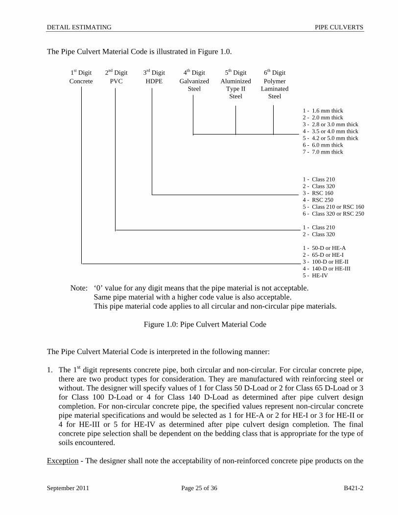
The Pipe Culvert Material Code is illustrated in Figure 1.0. 1st Digit 2nd Digit 3rd Digit 4th Digit 5th Digit 6th Digit
Concrete PVC HDPE Galvanized Steel
Aluminized Type II Steel
Polymer Laminated
Steel
1.6 mm thick 2.0 mm thick 2.8 or 3.0 mm thick 3.5 or 4.0 mm thick 4.2 or 5.0 mm thick 6.0 mm thick 7.0 mm thick Class 210 Class 320 RSC 160 RSC 250 Class 210 or RSC 160 Class 320 or RSC 250 Class 210 Class 320 50-D or HE-A 65-D or HE-I 100-D or HE-II 140-D or HE-III HE-IV
1 - 2 - 3 - 4 - 5 - 6 - 7 - 1 - 2 - 3 - 4 - 5 - 6 - 1 - 2 - 1 - 2 - 3 - 4 - 5 -
Note: ‘0’ value for any digit means that the pipe material is not acceptable. Same pipe material with a higher code value is also acceptable. This pipe material code applies to all circular and non-circular pipe materials.
Figure 1.0: Pipe Culvert Material Code
The Pipe Culvert Material Code is interpreted in the following manner: 1. The 1st digit represents concrete pipe, both circular and non-circular. For circular concrete pipe,
there are two product types for consideration. They are manufactured with reinforcing steel or without. The designer will specify values of 1 for Class 50 D-Load or 2 for Class 65 D-Load or 3 for Class 100 D-Load or 4 for Class 140 D-Load as determined after pipe culvert design completion. For non-circular concrete pipe, the specified values represent non-circular concrete pipe material specifications and would be selected as 1 for HE-A or 2 for HE-I or 3 for HE-II or 4 for HE-III or 5 for HE-IV as determined after pipe culvert design completion. The final concrete pipe selection shall be dependent on the bedding class that is appropriate for the type of soils encountered.
Exception - The designer shall note the acceptability of non-reinforced concrete pipe products on the
September 2011 Page 25 of 36 B421-2

DETAIL ESTIMATING PIPE CULVERTS
Quantities – Pipe Culvert sheet in the Contract. This will be done as a note to the tender item to indicate the application to this pipe product in all locations or as a note to a quantity if this condition only applies to one pipe location. 2. The 2nd digit represents PVC pipes. There are two product types for consideration. They are
manufactured with a smooth inside and a ribbed outside wall or with a smooth inside and outside wall. The designer will specify acceptable PVC pipe with values of 1 for Class 210 kpa (SDR 41) or 2 for Class 320 kpa (SDR 35) strength for either product type as determined after pipe culvert design completion.
3. The 3rd digit represents HDPE pipes. There are two product types for consideration. They are manufactured with a smooth inside and a corrugated outside wall (< 900 mm diameter) or with a smooth inside and outside wall (> 840 mm diameter). Dependent upon the diameter required, the designer will specify values of 1 for Class 210 kpa or 2 for Class 320 kpa strength or 3 for RSC 160 (Ring Stiffness Constant) or 4 for RSC 250 as determined after pipe culvert design completion. In certain cases where product diameters overlap, the designer can specify 5 for Class 210 or RSC 160 (Ring Stiffness Constant) or 6 for Class 320 or RSC 250 to indicate acceptability of both smooth inside wall product types.
4. The 4th, 5th and 6th digits all represent steel pipe products. There are three product lines for consideration. They are manufactured as corrugated steel pipe (CSP), spiral rib steel pipe (SRSP) and structural plate pipe (SPP). SRSP is a smooth pipe while CSP and SPP are corrugated pipes. CSP and SRSP products come in three coatings; galvanized, aluminized type II and polymer laminated while SPP is only available with a galvanized coating. CSP products are available with 1.6, 2.0, 2.8, 3.5 and 4.2 mm thick walls, SRSP products are available with 1.6, 2.0 and 2.8 mm thick walls while SPP products are available with 3.0, 4.0, 5.0, 6.0 and 7.0 mm thick walls. Finally, certain diameters of CSP are available in two corrugation profiles, 68 x13 and 125 x 25. The 4th digit is used for specifying galvanized steel pipe products. Values from 1 through 5 are used to specify the minimum wall thickness for CSP and SRSP products as determined by design. Values from 3 through 7 are used to specify the minimum wall thickness for SPP products as determined by design. The 5th digit is used for specifying aluminized type II steel pipe products. Values from 1 through 5 are used to specify the minimum wall thickness for CSP and SRSP products as determined by design.
The 6th digit is used for specifying polymer laminated steel pipe products. Values from 1 through 5 are used to specify the minimum wall thickness for CSP and SRSP products as determined by design. Exception - For some diameters, CSP is available with two corrugation profiles. The pipe
September 2011 Page 26 of 36 B421-2

DETAIL ESTIMATING PIPE CULVERTS
material durability analysis may determine a single wall thickness for both CSP product lines while the structural analysis of the pipe materials determines a different wall thickness for each CSP product lines. The designer shall identify the minimum wall thickness through the Pipe Material Code and note the greater wall thickness requirement of the other pipe product on the Quantities – Pipe Culverts sheet in the Contract. This shall be done as a note to the tender item to indicate the greater wall thickness requirement of this pipe product in all locations on the contract or as a note to a quantity if the greater wall thickness requirement of this pipe product only applies to one pipe location. Refer to the CPS Master Item list for actual pipe culvert tender items that are available. A separate pipe culvert tender item is required for individual base pipe diameters. Pipe Culvert Tender Item Example: The following information has been determined through design analysis and has been provided here only as an illustrative example to assist the designer. From the pipe culvert hydraulic analysis, the base pipe diameter needed to satisfy hydraulic capacity requirements is 1200 mm based on smooth inner wall pipe characteristics. The hydraulic analysis also found that smooth inner walled pipes up to 1220 mm in diameter and corrugated inner wall pipes beginning at 1400 mm up to 1500 mm in diameter satisfied the hydraulic requirements as well for this pipe culvert location. From the structural analysis, pipe products in these diameter ranges that satisfied the height of fill requirements were Class 100 D-Load reinforced concrete or RSC 250 smooth inside and outside HDPE or 2.0 mm thick walled steel pipe products. The DSL requirements have been set at 75 years for the highway facility. The pipe material durability analysis identified concrete or Class 320 PVC or 2.8 mm thick walled galvanized or 2.0 mm thick walled aluminized type II or 1.6 mm thick walled polymer laminated steel pipe products as acceptable for this installation. In summary, the following list of pipe products has, through design, been found to be acceptable for this pipe culvert.
1200 mm Reinforced Class 65 D-Load Concrete pipe 1220 mm RSC 250 HDPE pipe 1200 mm Galvanized spiral rib steel pipe, 2.8 mm wall thickness 1200 mm Aluminized Type II spiral rib steel pipe, 2.0 mm wall thickness 1200 mm Polymer Laminated spiral rib steel pipe, 2.0 mm wall thickness 1400 or 1500 mm Galvanized corrugated steel pipe, 2.8 mm wall thickness 1400 or 1500 mm Aluminized corrugated steel pipe, 2.0 mm wall thickness 1400 or 1500 mm Polymer Laminated corrugated steel pipe, 2.0 mm wall thickness
The designer would specify the above pipe culvert information into the Contract with a single Pipe Culvert Tender Item as shown below.
September 2011 Page 27 of 36 B421-2

DETAIL ESTIMATING PIPE CULVERTS
1200 mm Pipe Culvert 1200 + 20 S 204322 1400 + 100 C 000322
If either pipe type were found to have not been acceptable, the appropriate line in the pipe culvert tender item would not be entered. All required pipe sizes, for the contract, would be represented, in a similar fashion, on the “Quantity – Pipe Culvert” sheet as separate pipe culvert tender items in the same format to identify all acceptable pipe products complete with material specifications for each pipe culvert location.
September 2011 Page 28 of 36 B421-2
DETAIL ESTIMATING PIPE CULVERTS
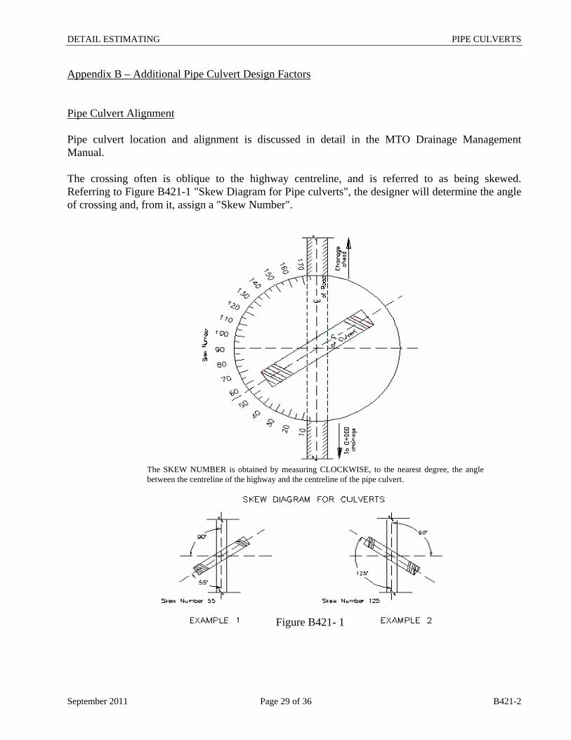
Appendix B – Additional Pipe Culvert Design Factors Pipe Culvert Alignment Pipe culvert location and alignment is discussed in detail in the MTO Drainage Management Manual. The crossing often is oblique to the highway centreline, and is referred to as being skewed. Referring to Figure B421-1 "Skew Diagram for Pipe culverts", the designer will determine the angle of crossing and, from it, assign a "Skew Number".
The SKEW NUMBER is obtained by measuring CLOCKWISE, to the nearest degree, the angle between the centreline of the highway and the centreline of the pipe culvert.
Figure B421- 1
September 2011 Page 29 of 36 B421-2
DETAIL ESTIMATING PIPE CULVERTS
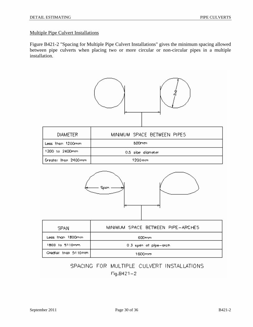
Multiple Pipe Culvert Installations Figure B421-2 "Spacing for Multiple Pipe Culvert Installations" gives the minimum spacing allowed between pipe culverts when placing two or more circular or non-circular pipes in a multiple installation.
September 2011 Page 30 of 36 B421-2
DETAIL ESTIMATING PIPE CULVERTS
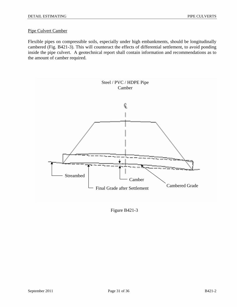
Pipe Culvert Camber Flexible pipes on compressible soils, especially under high embankments, should be longitudinally cambered (Fig. B421-3). This will counteract the effects of differential settlement, to avoid ponding inside the pipe culvert. A geotechnical report shall contain information and recommendations as to the amount of camber required.
Steel / PVC / HDPE Pipe Camber
Streambed Camber
Final Grade after Settlement Cambered Grade
Figure B421-3
September 2011 Page 31 of 36 B421-2
DETAIL ESTIMATING PIPE CULVERTS
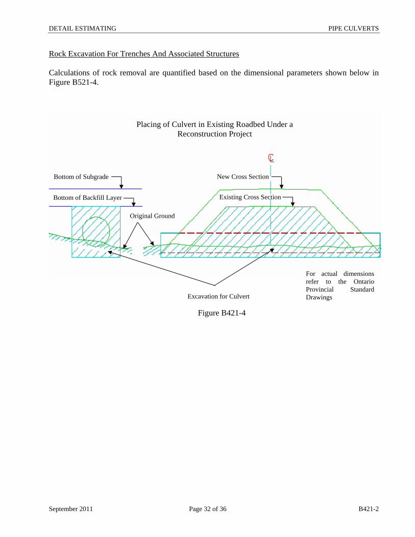
Rock Excavation For Trenches And Associated Structures Calculations of rock removal are quantified based on the dimensional parameters shown below in Figure B521-4.
Bottom of Subgrade
Bottom of Backfill Layer
Original Ground
New Cross Section
Existing Cross Section
Excavation for Culvert
Placing of Culvert in Existing Roadbed Under a Reconstruction Project
Figure B421-4
For actual dimensions refer to the Ontario Provincial Standard Drawings
September 2011 Page 32 of 36 B421-2
DETAIL ESTIMATING PIPE CULVERTS
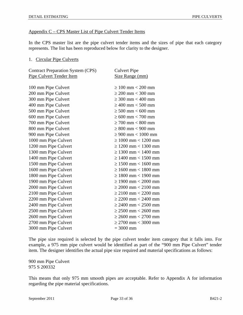
Appendix C – CPS Master List of Pipe Culvert Tender Items In the CPS master list are the pipe culvert tender items and the sizes of pipe that each category represents. The list has been reproduced below for clarity to the designer. 1. Circular Pipe Culverts Contract Preparation System (CPS) Culvert Pipe Pipe Culvert Tender Item Size Range (mm) 100 mm Pipe Culvert ≥ 100 mm < 200 mm 200 mm Pipe Culvert ≥ 200 mm < 300 mm 300 mm Pipe Culvert ≥ 300 mm < 400 mm 400 mm Pipe Culvert ≥ 400 mm < 500 mm 500 mm Pipe Culvert ≥ 500 mm < 600 mm 600 mm Pipe Culvert ≥ 600 mm < 700 mm 700 mm Pipe Culvert ≥ 700 mm < 800 mm 800 mm Pipe Culvert ≥ 800 mm < 900 mm 900 mm Pipe Culvert ≥ 900 mm < 1000 mm 1000 mm Pipe Culvert ≥ 1000 mm < 1200 mm 1200 mm Pipe Culvert ≥ 1200 mm < 1300 mm 1300 mm Pipe Culvert ≥ 1300 mm < 1400 mm 1400 mm Pipe Culvert ≥ 1400 mm < 1500 mm 1500 mm Pipe Culvert ≥ 1500 mm < 1600 mm 1600 mm Pipe Culvert ≥ 1600 mm < 1800 mm 1800 mm Pipe Culvert ≥ 1800 mm < 1900 mm 1900 mm Pipe Culvert ≥ 1900 mm < 2000 mm 2000 mm Pipe Culvert ≥ 2000 mm < 2100 mm 2100 mm Pipe Culvert ≥ 2100 mm < 2200 mm 2200 mm Pipe Culvert ≥ 2200 mm < 2400 mm 2400 mm Pipe Culvert ≥ 2400 mm < 2500 mm 2500 mm Pipe Culvert ≥ 2500 mm < 2600 mm 2600 mm Pipe Culvert ≥ 2600 mm < 2700 mm 2700 mm Pipe Culvert ≥ 2700 mm < 3000 mm 3000 mm Pipe Culvert = 3000 mm The pipe size required is selected by the pipe culvert tender item category that it falls into. For example, a 975 mm pipe culvert would be identified as part of the “900 mm Pipe Culvert” tender item. The designer identifies the actual pipe size required and material specifications as follows: 900 mm Pipe Culvert 975 S 200332 This means that only 975 mm smooth pipes are acceptable. Refer to Appendix A for information regarding the pipe material specifications.
September 2011 Page 33 of 36 B421-2
DETAIL ESTIMATING PIPE CULVERTS
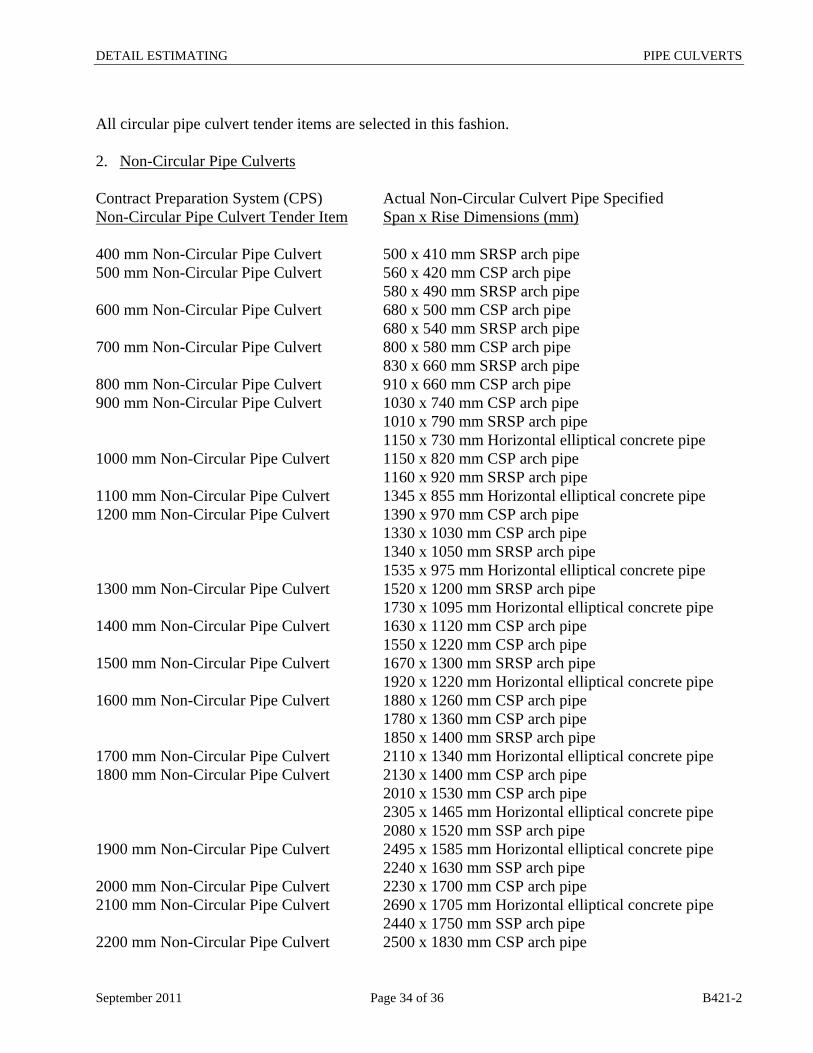
All circular pipe culvert tender items are selected in this fashion. 2. Non-Circular Pipe Culverts Contract Preparation System (CPS) Actual Non-Circular Culvert Pipe Specified Non-Circular Pipe Culvert Tender Item Span x Rise Dimensions (mm) 400 mm Non-Circular Pipe Culvert 500 x 410 mm SRSP arch pipe 500 mm Non-Circular Pipe Culvert 560 x 420 mm CSP arch pipe 580 x 490 mm SRSP arch pipe 600 mm Non-Circular Pipe Culvert 680 x 500 mm CSP arch pipe 680 x 540 mm SRSP arch pipe 700 mm Non-Circular Pipe Culvert 800 x 580 mm CSP arch pipe 830 x 660 mm SRSP arch pipe 800 mm Non-Circular Pipe Culvert 910 x 660 mm CSP arch pipe 900 mm Non-Circular Pipe Culvert 1030 x 740 mm CSP arch pipe 1010 x 790 mm SRSP arch pipe 1150 x 730 mm Horizontal elliptical concrete pipe 1000 mm Non-Circular Pipe Culvert 1150 x 820 mm CSP arch pipe 1160 x 920 mm SRSP arch pipe 1100 mm Non-Circular Pipe Culvert 1345 x 855 mm Horizontal elliptical concrete pipe 1200 mm Non-Circular Pipe Culvert 1390 x 970 mm CSP arch pipe 1330 x 1030 mm CSP arch pipe 1340 x 1050 mm SRSP arch pipe 1535 x 975 mm Horizontal elliptical concrete pipe 1300 mm Non-Circular Pipe Culvert 1520 x 1200 mm SRSP arch pipe 1730 x 1095 mm Horizontal elliptical concrete pipe 1400 mm Non-Circular Pipe Culvert 1630 x 1120 mm CSP arch pipe 1550 x 1220 mm CSP arch pipe 1500 mm Non-Circular Pipe Culvert 1670 x 1300 mm SRSP arch pipe 1920 x 1220 mm Horizontal elliptical concrete pipe 1600 mm Non-Circular Pipe Culvert 1880 x 1260 mm CSP arch pipe 1780 x 1360 mm CSP arch pipe 1850 x 1400 mm SRSP arch pipe 1700 mm Non-Circular Pipe Culvert 2110 x 1340 mm Horizontal elliptical concrete pipe 1800 mm Non-Circular Pipe Culvert 2130 x 1400 mm CSP arch pipe 2010 x 1530 mm CSP arch pipe 2305 x 1465 mm Horizontal elliptical concrete pipe 2080 x 1520 mm SSP arch pipe 1900 mm Non-Circular Pipe Culvert 2495 x 1585 mm Horizontal elliptical concrete pipe 2240 x 1630 mm SSP arch pipe 2000 mm Non-Circular Pipe Culvert 2230 x 1700 mm CSP arch pipe 2100 mm Non-Circular Pipe Culvert 2690 x 1705 mm Horizontal elliptical concrete pipe 2440 x 1750 mm SSP arch pipe 2200 mm Non-Circular Pipe Culvert 2500 x 1830 mm CSP arch pipe
September 2011 Page 34 of 36 B421-2

DETAIL ESTIMATING PIPE CULVERTS
2400 mm Non-Circular Pipe Culvert 2800 x 1950 mm CSP arch pipe 3070 x 1950 mm Horizontal elliptical concrete pipe 2590 x 1880 mm SSP arch pipe 2500 mm Non-Circular Pipe Culvert 2690 x 2080 mm SSP arch pipe The pipe size required is selected by the pipe culvert tender item category that it falls into. For example a 1850 x 1400 mm SRSP pipe culvert or a 1880 x 1260 mm CSP arch pipe would be identified as part of the “1600 mm Non-Circular Pipe Culvert” tender item. The designer identifies the actual pipe size required and material specifications, assuming both materials are acceptable, as follows: 1600 mm Non-Circular Pipe Culvert 1600 S 200322 This means that only 1600 mm category concrete or steel smooth non-circular pipes are acceptable. Refer to Appendix A for information regarding the pipe material specifications. All non-circular pipe culvert tender items are selected in this fashion. 3. Pipe Culvert Extensions Contract Preparation System (CPS) Pipe Culvert Extension Tender Item xxx mm Pipe Culvert Extensions xxx S xxxxxx xxx C xxxxxx The designer selects the pipe culvert tender item and enters the pipe size required for the pipe culvert extension. For example, an 800 mm pipe culvert extension would be identified as an 800 mm Pipe Culvert Extension tender item. The designer identifies the pipe size, type and material specifications as follows: 800 mm Pipe Culvert Extension 800 S 200332 800 C 000332 This means that only 800 mm pipes are acceptable. Refer to Appendix A for information regarding the pipe material specifications. All pipe culvert extension tender items are selected in this fashion. 4. Non-Circular Pipe Culvert Extensions Contract Preparation System (CPS) Non-Circular Pipe Culvert Extension Tender Item
September 2011 Page 35 of 36 B421-2

DETAIL ESTIMATING PIPE CULVERTS
xxx mm Non-Circular Pipe Culvert Extensions xxx S xxxxxx xxx C xxxxxx The designer selects the pipe culvert tender item and enters the equivalent pipe diameter required for the pipe culvert extension. For example, an equivalent 1200 mm diameter non-circular pipe culvert extension would be identified as a 1200 mm Non-Circular Pipe Culvert Extension tender item. The designer identifies the pipe size, type and material specifications as follows: 1200 mm Non-Circular Pipe Culvert Extension 1200 S 200332 1200 C 000332 This means that only 1200 mm pipes are acceptable. Refer to Appendix A for information regarding the pipe material specifications. All non-circular pipe culvert extension tender items are selected in this fashion.
September 2011 Page 36 of 36 B421-2