detailed project report for connecting …
TRANSCRIPT

DETAILED PROJECT REPORT
FOR CONNECTING LAKSHADWEEP ISLANDS ON SUBMARINE OFC
Contents
1.0 EXECUTIVE SUMMARY 11
1.1 BACKGROUND 11 1.2 METHODOLOGY TO PREPARE THE DPR 11 1.3 BROAD FINDINGS 12 1.3.1 SUBMARINE CABLE LENGTH AND TYPE 12 1.3.2. SITE SURVEY 12 1.3.3. SUBMARINE SYSTEM DESIGN 12 1.3.4. PROPOSED TOPOLOGIES 14 1.3.5 PROJECT TIMELINES 16
2.0 INTRODUCTION 17
2.1 ABOUT LAKSHADWEEP 17 2.2 PRESENT TELECOM SCENARIO 18 2.3 ISSUES IN PRESENT TELECOM CONNECTIVITY 19 2.4 CHALLENGES IN DEVELOPING RELIABLE TELECOM CONNECTIVITY 19 2.5 TCIL SCOPE OF WORK 19
3.0 ASSESMENT OF TELECOM CONNECTIVITY REQUIREMENTS 22
3.1 IDENTIFY THE FACTORS REQUIRING RELIABLE TELECOM CONNECTIVITY 22 3.2 ESTIMATION OF TELECOM BANDWDITH REQUIREMENT IN LAKSHADWEEP 23 4.1 ABOUT SUBMARINE OFC SYSTEM 26 4.1.1 WET PLANT COMPONENTS 27 4.1.2 DRY PLANT 32 4.2 CAPACITY OF SUBMARINE OFC LINKS 33 4.3. MARINE SERVICES 43 4.4. WORLDWIDE CABLE NETWORKS 48
5.0 DESKTOP STUDY 52
5.1. SITE VISIT FINDINGS 53 5.2. CABLE TYPES 55 5.3. CABLE BURIAL 56
6. LAKSHADWEEP NETWORK ARCHITECTURE 72
6.1. BACKGROUND 72 6.1.1. TRAI REPORT 72

6.2. ROUTE SELECTION 73 6.3. TOPOLOGY 73 6.4. SYSTEM DESIGN 79 6.4.1. NUMBER OF FIBER IN LAKSHADWEEP SUBMARINE OPTICAL FIBER CABLE 79 6.4.2. SUBMARINE EQUIPMENT CONFIGURATION IN LAKSHADWEEP 81 6.5. KEY DESIGN PARAMETERS 84 6.6. REDUNDANCY 85
7. PROJECT COST 87
7.1. CAPEX (CAPITAL EXPENDITURE) 87 7.2. OPEX 92
8. TECHNICAL SPECIFICATIONS OF SUBMARINE COMPONENTS 95
9. EXECUTION METHODOLOGY & TIMELINES 101
9.1. IMPLEMENTATION METHODOLOGY 101 9.1.1. DESKTOP SURVEY 101 9.1.2. MARINE SURVEY 102 9.1.3. EXECUTION OF WORKS 102 9.2. SCOPE OF WORK 103 9.3. TIMELINE CHART 108 9.3.1. TIME TO AWARD THE PROJECT 108 9.3.2. SUBMARINE EXECUTION OF PROJECT 109
10. PERMITS & LICENSES 111
10.1. INTRODUCTION 111 10.2. GENERAL PERMITTING REQUIREMENTS 112 10.3. INDIA PERMITTING 114 10.3.1. PERMIT IN PRINCIPLE (PIP) 114 10.3.2. OPERATIONAL PERMITS 115 10.4. LAKSHADWEEP AND MINICOY ISLANDS 116 10.5. PERMITTING PROCEDURE & LEAD-TIME SUMMARY 116
11. RISKS & HAZARDS 119
12. PROJECT MANAGEMENT CONSULTANT 126
12.1. PROJECT MANAGEMENT ASPECTS 126 12.2. STRUCTURE - PROJECT MANAGEMENT UNIT 131

12.3. OWNERSHIP ISSUES 131 12.4. COMMERCIAL ISSUES 132

Figure 1: Evolution of Submarine Equipment Technology ...................................................................... 14 Figure 2: Inter-island Ring Connectivity .................................................................................................. 15 Figure 3: Submarine System Components .............................................................................................. 26 Figure 4: Types of submarine cable (different levels of protective layers) .............................................. 27 Figure 5: Details of Armouring in Submarine OFC................................................................................... 28 Figure 6: Repeater v/s Repeater Less ..................................................................................................... 29 Figure 7: Equalizer ................................................................................................................................. 31 Figure 8: Point to point Submarine Cable Link ........................................................................................ 32 Figure 9: Land Joint installed in Beach manhole (Courtesy: ASN) ........................................................... 33 Figure 10: Evolution of Submarine Equipment Technology .................................................................... 34 Figure 11: Channel Spacing in a Submarine System ................................................................................ 34 Figure 12: A cable laying ship at sea ....................................................................................................... 43 Figure 13: OTDR .................................................................................................................................... 47 Figure 14: COTDR .................................................................................................................................. 47 Figure 15: Maintenance Zone ................................................................................................................ 48 Figure 16: Submarine cable network worldwide .................................................................................... 48 Figure 17: BMH at Kalpeni Island ........................................................................................................... 57 Figure 18: Route Position List Kochi to Kalpeni ....................................................................................... 62 Figure 19: Straight Line Diagram (Kochi to Kalpeni) ................................................................................ 63 Figure 20 Straight Line Diagram (Kalpeni to Androth) ............................................................................ 64 Figure 21: Androth to Amini .................................................................................................................. 65 Figure 22: Kadmat to Amini ................................................................................................................... 65 Figure 23: Kadmat to Kiltan ................................................................................................................... 66 Figure 24: Kiltan to Chetlat .................................................................................................................... 66 Figure 25: Chetlat to Bitra ...................................................................................................................... 67 Figure 26: Bitra to Bangaram ................................................................................................................. 68 Figure 27: Bangaram to Agatti ............................................................................................................... 68 Figure 28: Agatti to AMini ...................................................................................................................... 69 Figure 29 Agatti to Kavaratti .................................................................................................................. 69 Figure 30 Kavaratti to Kalpeni ................................................................................................................ 70 Figure 31: Kalpeni to Minicoy ................................................................................................................ 71 Figure 32: TRAI Report ........................................................................................................................... 72 Figure 33: Linear Connectivity................................................................................................................ 74 Figure 34: Ring Connectivity (Option 1) .................................................................................................. 74 Figure 35 Ring Connectivity (Option 2) .................................................................................................. 75 Figure 36Ring Connectivity (Option 3) ................................................................................................... 75 Figure 37: Ring Connectivity (Option 4) .................................................................................................. 76 Figure 38: Option 5 ................................................................................................................................ 76 Figure 39: Connectivity using BU ........................................................................................................... 78 Figure 40: Fiber Routing Diagram........................................................................................................... 83 Figure 41: Implementation Process...................................................................................................... 101 Figure 42: Activities In a Submarine Project ......................................................................................... 103 Figure 43: Gantt Chart for Project Execution ........................................................................................ 110 Figure 44: Maritime claims .................................................................................................................. 112

Tables:
Cases
Table 1: Segment –wise Route Length and Cable Length ........................................................................ 10 Table 2: Segment –wise Route Length and Cable Length (As per TRAI recommended topology)............. 11 Table 23: Submarine Physiography and Geology Risk Assessment........................................................ 131 Table 24: Environmental Factors Risk Assessment ............................................................................... 132 Table 25: Offshore Activities and Hazards Risk Assessment .................................................................. 134 Table 3: Segment –wise Route Length and Cable Length (topology 3) .................................................... 12 Table 5: Submarine Project Cost ............................................................................................................ 16 Table 6: Present telecom Bandwidth in Lakshadweep ............................................................................ 19 Table 7: Segments as per scope of work .......................................................................................... 21, 27 Table 8: Projected Bandwidth ................................................................................................................ 27 Table10: Landing station equipment installation dimensions ................................................................. 46 Table11: KLI Currently Used BMH locations ........................................................................................... 60 Table12:KLI CLS Site Summary ............................................................................................................... 62 Table14: Segment-wise Route & Cable Length ....................................................................................... 65 Table15: TRAI Recoomendation ...................................................................................................... passim Table16: Submarine cost for different Toplogy ............................................................................... passim Table17: Key Design Parameters ............................................................................................................ 87 Table18: Break up of submarine Cost under various Had (in %age) ........................................................ 93 Table19 : Submarine Cost ..................................................................................................................... 94 Table19: Total CAPEX............................................................................................................................. 96 Table20: IUT-T recommendations on Submarine OFC System .............................................................. 106 Table20: OPEX ....................................................................................................................................... 99 Table22: Environment related Permits for Cable Landing in Lakshadweep islands ............................. 127 Table24: Proposed staffing level ......................................................................................................... 142 Table4: Cable systems landing in India since 2005 and the technology............................................. 15, 40 Table9: Type of OFC laid vis-à-vis Water Depth ...................................................................................... 31
AAE-1 – Asia-Africa-Europe 1 ACMA – Atlantic Cable Maintenance & repair Agreement ADCN – Avionics Data Communication Network ANI – Andaman and Nicobar Islands ASN – Abstract Syntax Notation BBG – Bay of Bengal Gateway BBNL – Bharat Broadband Network BMH – Beach ManHoles BMS – Building Management System BNOC – Backup Network Operations Center BSNL – Bharat Sanchar Nigam Limited BTS – Base Transceiver station BU – Branching Units CAPEX – Capital Expenditure CCITT – Consultative Committee for International Telephony and Telegraphy CCTV – Closed Circuit Tele Vision CoF – Commissioner of Fisheries CRE – Cable Route Engineering CRZ – Coastal Regulation Zone CRZ – Coastal Regulation Zone CTB – Cable Termination Box CTR – Cable Termination Rack CZMA – Coastal Zone Management Authority DA – Double Armor DCDB – Direct Current Distribution Board DCE – Data Circuit terminating Equipment DCN – Data Communication Network DCN – Data Communication Network
DG S– Directorate General of Shipping DLS – Digital Line Segment DoT – department of Telecom DPR – Detailed Project Report DRC – Disaster Recovery Center DTE – Data Terminal Equipment DTS – Desk Top Study DWDM – Dense Wavelength Division Multiplexing EEZ – Exclusive Economic Zone EEZ – Exclusive Economic Zone EIA – Environmental Impact Assessment EIG – Endurance International Group EMC - Electromagnetic Compatibility EMS – Element Management System EOI – Expression of Interest EPABX – Electronic Private Automatic Branch Exchange ETSI – European Telecommunications Standards Institute
FAD – Faculty and Academic Development FAT – Factory Acceptance Test FDF – Fiber Distribution Frame FODAG – Flag Officer Defence Advisory Group FP – Fiber Pair GbE – Gigabit Ethernet GBI – Gulf Bridge International GBPS – GigaBits Per Second GDP – Gross Domestic Product GIS – Geographical Information Systems GP – Gram Panchayats GR – General Requirements GST – Goods and Service Tax HD – High Denition HDPE – High Density Poly Ethylene HOTO – HandOver / TakeOver HV – High Voltage ICPC – International Cable Protection Committee ICT – Information and Communications Technology IE – Interface Equipment IEC – International Electro technical Commission IEEE – Institute of Electrical and Electronics Engineers I-ME-WE – India-Middle-East-Western Europe IOR – Importer on Record IP – Internet Protocol IPPM – IP Performance Metrics ISO – Indian Standard Organization ITU-T – International Telecommunication Union – Telecommunications KLI – Kochi Lakshadweep Islands LCT – Local Craft Terminal LSA – Local Service Area LTE – Long-Term Equipment LW – Light Weight LWA – Light Weight Armor LWP – Light Weight Protected MBPS – Mega Bits per Second MC – Maintenance Controller MECMA – Mediterranean Cable Maintenance Agreement MHz – Mega Hertz MOD – Ministry of Defense MOEF – Ministry of Environment and Forests MOHA – Ministry of Home Affairs MSP – Multiplex Section Protection NAZ – North American Zone NEC – National Executive Committee NEs- Network Elements
NLD – National Long Distance NMS – Network Management System NMS – network Management System NOC – Network Operations Center NRZ/RZ QPSK – Non Return to Zero/Return to Zero Quadrature Phase Shift Keying O&M – Operations & maintenance OAM – Operation And Maintenance OD – Outside Diameter ODF – Optical Distribution Frame OFC – Optical Fiber Cable OPEX – Operating Expenditure OSAS – Open Source Advance Solutions OSI – Open Systems Interconnection OSI – Open Systems Interconnection OSS – Office of Strategic Services OTN – Optical Transport Network PCM – Pulse Code Modulation PEU – Passive Equalizer PFE – Power Feeding Earth PIP – Permit in Principle PMC – Project Management Consultant PoW – Plan of Work PRBS – Pseudo Random Binary Sequence RA – Rock Armor RFC – Request for Comments RFP – Request For Proposal RoW – Right of Way RPL – Route Position List RSSE – Recommendation Systems for Software Engineering SA – Single Armor SAT – System Assembly Tests SDH – Synchronous Digital Hierarchy SP – Service Providers SEAIOCMA – South East Asia and Indian Ocean Cable Maintenance Agreement SIE – SDH Interface Equipment SLD – Straight Line Diagram SLTE – Submarine Line Terminal Equipment SMPS – Switch Mode Power Supply SMS – Short Message Service SMW4 – SEA-ME-WE 4 –South East Asia-Middle East-Western Europe 4 SMW5 - SMW4 – SEA-ME-WE 5 –South East Asia-Middle East-Western Europe 5 SNCP – Sub-Network Connection Protection SONET – Synchronous Optical Network SoW – Scope of Work SPA – Special Protection Area
SPL – Specified Period License SSU – Synchronous Supply Unit SWAN – State Wide Area Networks TbE – Terabit Ethernet Tbps – Tera bits per second TCIL – Telecommunications Consultants India Limited TCP/IP – Transmission Control Protocol/ Internet Protocol TRAI – Telecom Regulatory Authority of India TS – Territorial Seas UJ – Universal Joint UPS – Un-interruptible Power Supply USOF - Universal Services Obligation Fund UT – Union Territory UXo – Unexploded Bombs VESDA – Very Early Smoke Detection Apparatus WDM – Wavelength Division Multiplexing YZ – Yokohama Zone

1.0 EXECUTIVE SUMMARY
1.1 Background TCIL submitted the Cost Benefit Analysis Report for submarine OFC connectivity of Lakshadweep Islands to mainland India in July 2016. The in principle approval for this project was given by Telecom Commission based on this report. USOF then awarded the work of preparation of a Detailed Project Report (DPR) based on Desktop Study (DTS) of connecting all inhabited islands (11) of Lakshadweep on submarine Optical fiber network to TCIL on 02.02.2018. It was proposed to connect the 11 inhabited islands of Lakshadweep to the mainland at Kochi through submarine Optical Fiber Cable. However ,in a meeting at Kochi attended by TCIL, BSNL, Lakshadweep administration and Navy representatives; both the Lakshadweep administration and Navy Southern Command representatives expressed that it would be prudent to extend the connectivity from Minicoy island of Lakshadweep to Trivandrum through submarine OFC seeing its strategic importance from country’s defense perspective. The Trivandrum to Kochi segment would be a terrestrial OFC of BSNL and this configuration would provide physical ring redundancy to all islands of Lakshadweep group of islands with mainland at Kochi and Trivandrum. The in principle approval from DoT to include for Minicoy – Trivandrum link in DPR was received in June’18.
The DPR was made after carrying out the site survey of Lakshadweep islands and desktop study of the ocean database for route identification.
1.2 Methodology to Prepare the DPR TCIL was awarded the assignment of preparing DPR of connecting 11 islands of Lakshadweep based on Desktop Study.
The Desktop Study is a specialized job which involves study of ocean database and marine charts, site visits to identify the submarine cable route and landing location. It involves carrying out the research bathymetry, submarine geology, oceanography, seafloor and shallow seabed lithology, currents, metrology, weather, climatography, seismology, tides, permits, other sea-bed users, fishing/ biological factors, shipping in order to identify cable route. It also includes Cable Route Engineering (CRE) that shall include the route feasibility, perceived risks, routing selection and landings for implementation.
TCIL has awarded the Desktop Study of this project to a specialized agency through its extant tendering policy.
A kick off meeting with the selected agency was conducted at TCIL office on 19th Feb 2018, also attended by USOF. In this meeting, the agency gave a presentation on the approach and methodology of carrying out the DTS study. This was followed by a meeting in Kochi on 9th March 2018 attended by officials from Lakshadweep Administration, Navy Southern Command, BSNL and TCIL. In this meeting the connectivity options of connecting Lakshadweep islands and the expediting the required permits to visit Lakshadweep islands were discussed.
The permission to visit the islands to carry out survey was submitted with the Lakshadweep Administration. On receipt of permissions, the DTS agency carried out the site visit in all 11 islands to identify the locations of Cable landing station and Beach Manholes from 23.03.2018 to 10.04.2018.

The DTS agency submitted its Desktop Study report based on the results of site visits and study of ocean database. The DPR was submitted based on DTS findings , inputs from various submarine vendors and BSNL A&N Islands submarine connectivity tender.
1.3 Broad Findings
1.3.1 Submarine Cable length and Type Based on the Desktop study, the details of submarine OFC length and type of submarine cable to be used is tabulated below:
SEGMENT ROUTE
LENGTH (KM)
CABLE LENGTH
(KM)
DA (KM)
SA (KM)
LWP (KM)
Seg 1 Kochi to Kalpeni 288.44 297.46 66.65 18.07 212.74
Seg 2 Kalpeni to Androth 118.91 123.34 7.25 3.78 112.31
Seg 3 Androth to Amini 128.94 133.77 6.31 4.52 122.94
Seg 4 Amini to Kadmat 22.80 23.45 2.86 5.88 14.72
Seg 5 Kadmat to Kiltan 57.47 59.47 1.68 8.53 49.27
Seg 6 Kiltan to Chetlat 51.63 53.47 2.60 4.99 45.88
Seg 7 Chetlat to Bitra 79.66 82.60 2.47 5.87 74.26
Seg 8 Bitra to Bangaram 78.25 81.09 3.31 6.48 71.30
Seg 9 Bangaram to Agatti 47.17 48.48 3.82 15.63 29.03
Seg 10 Agatti to Amini 106.77 110.51 3.23 14.70 92.58
Seg 11 Agatti to Kavaratti 78.31 80.91 2.01 15.96 62.95
Seg 12 Kavaratti to Kalpini 181.63 188.64 1.89 6.69 180.64
Seg 13 Kalpeni to Minicoy 242.71 252.25 2.06 3.52 246.67
Seg14 Minicoy to T’puram 438.51 453.76 42.70 34.40 376.65
Total: 1921.16 1989.19 148.81 149.00 1681.94 Note: DA: Double Armored, SA- Single Armored, LWP- Light Weight Protected
1.3.2. Site Survey The main highlights of site survey carried at all islands and at Kochi and Trivandrum of DTS Report may be referred in Chapter-5 (Desktop Study). The main finding is the identification of Beach manhole (BMH) where the cable can be terminated on shore and cable landing station (CLS).
The latitude and longitude of two potential BMH locations are identified on each island after consultation with port authority, BSNL officers and considering local factors. Most of the islands have BSNL exchange with sufficient space (1st floor needs to be constructed) and are identified as appropriate CLS locations except in Bangaram and Bitra where new CLS shall need to be constructed.
1.3.3. Submarine System Design In this regard, the capacity of the existing submarine cables landing in India was also analyzed. It was found that mostly the current working system are upgraded to 100Gbps and the new upcoming are

designed for digital coherent 100 Gbps technology. The figure below gives a snapshot of cable landing in India, Indian Telecom owners, associated technology upgrade and fiber pair.
Sr No
Cable System
Year of commissioning
1st Upgrade
2nd Upgrade
3rd Upgrade
4th upgrade
Owners (nos.)
Indian telcos
No. of fiber pair
1 SMW4 2005 2007 2009 2012 2014 17 TataComm. Airtel
2 (10G) (10G) (10G) (40G) (100G)
2 SEACOM 2009 2013 - - - 6 Tata 4 (10G) (40G)
3 I-ME-WE 2010 2012 2015 9 Tata Comm. Airtel
3
(10G) (40G) (100G) 4 EIG 2011 2013 2015 - - 14 Airtel,
BSNL, Vodafone
3
(10G) (100G) 100G 5 GBI 2012 2015 - - - 2 2
(10G) (100G) 6 BBG 2016 - - - - 7 Vodafone ,
Reliance 3
(100G)
7 SMW5 2016 - - - - 14 3
(100G) 8 AAE-1 2017 - - - - 12 Reliance
Jio Infocom 5
(100G) 9 i2i 2002 1 Airtel 8
(105X10 Gbps)
Table 4: Cable systems landing in India since 2005 and the technology With the advancement in digital coherent DWDM technology and the transmission in optical fiber, the adoption of 100Gbps DWDM in submarine networks significantly increases fiber capacity in a cost effective way. a) No. of Fiber Pairs (FP) As can be seen systems with 2 FP to 8 FP are common. The important points to be kept in mind while deciding the number of FP’s are: 1) Requirement 2) Cost 3) Topology Considering all above aspects and futuristic perspective for extension of submarine cable to nearby continents/ islands, six fiber pair has been proposed. The use of each fiber pair is envisaged as:
1 FP for commercial use
1 FP for Navy

4 FP as spare for providing fiber redundancy and future use for onwards extension to other continents.
b) System Dimensioning
The submarine system has evolved many folds in past years in terms of capacity that can be provisioned on each fiber pair.
The below diagram explains the evolution of capacities of DWDM systems over the past one and a half decade:
Courtesy: NEC
Figure 1: Evolution of Submarine Equipment Technology As on date 100 Gbps per wavelength systems are commercially being deployed and a DWDM system can have 80 lambdas which makes the system capacity 80 x 100 Gbps = 8 Terabits per second [Tbps].
Considering the bandwidth requirement of Lakshadweep, it is proposed to have a design capacity of 16 wavelengths with one wavelength (100Gbps) being dropped at each island using an Add Drop DWDM multiplexer on each island connected in ring topology.
1.3.4. Proposed Topologies It is proposed to connect the 11 inhabited islands of Lakshadweep to the mainland at Kochi through submarine Optical Fiber Cable. In the meeting at Kochi, both the Lakshadweep administration and Navy Southern Command representatives expressed that it would be prudent to connect Minicoy to Trivandrum through submarine OFC seeing its strategic importance from country’s defense perspective. The Trivandrum to Kochi segment would be a terrestrial OFC of BSNL
This will provide physical ring redundancy to all islands of Lakshadweep group of islands with mainland at Kochi and Trivandrum.

The in principle approval from DoT to carry out the DTS for Minicoy – Trivandrum link was received in June’18 and the same was carried out by the agency. The BoQ and cost for the same has been included in this submission.
The submarine OFC cable connectivity of Lakshadweep islands with mainland (India) at Kochi and T’Puram connected through Kalpeni and Minicoy islands respectively. The connectivity among islands and mainland can be made in number of ways i.e. linear or ring connectivity and direct connectivity or through Branching Unit. All the topologies are detailed and analysed in the “ Network Architecture” chapter.
- Connecting all 11 inhabited islands on submarine OFC (three inter-island rings)
Figure 2: Inter-island Ring Connectivity
Key Details
Route Length – 1921.16 km.
Cable Length – 1989.19 km. For the recommended topology option [Topology 1] i.e all 11 islands on submarine OFC below is the cost summary: S.No. Item Heads Cost (in Rs. Cr.)
1. Submarine System 860 2 Other CAPEX elements 49
Sub – Total (1) 909 3. Project Management Cost@10% 91
Sub – Total (2) 1000 4. Contingency@3% 30
TOTAL [including taxes] 1030 Table19: Total CAPEX
Note: 1. Other CAPEX elements include cost towards:
CLS construction & upgradation - estimated @5% of submarine cost
CRZ clearance and traffic surveillance equipment – provision of Rs. 6 cr. based on estimation of ANI project.

3. PMC: The cost incurred by Project execution agency and project monitoring agency. 4. Contingency: It includes cost towards vessel entry charges, currency fluctuation, inflation and any unforeseen expenses.
OPEX: The operational expenditure incurred in providing maintenance is categorized below:
Cable repair charges (in case of submarine cable cut)
AMC towards Submarine System
Operation & Management of Cable Landing Station
Preventive Maintenance
The estimated OPEX is approximately 4.39% of project cost. The budgetary estimate towards OPEX is taken as 5% of the CAPEX i.e. Rs 51Cr. per annum including 18% service Tax. A yearly escalation of 10% is taken while estimation of OPEX in subsequent years.
TOTAL PROJECT COST CAPEX 1030
OPEX for 5 years (10% escalation every year) 314 TOTAL COST (In Rs. Cr.) 1344
1.3.5 Project Timelines The project timeline depends on the time taken to award the project and the expected month of start as the execution of project depends on the weather of Lakshadweep islands. The island group face monsoon for a long period, the only favorable time period is between December to April.
Assuming an optimistic approach, and that the award of work to selected submarine vendor selected through tendering is done by early next year, it will take approximately 24 months for the project completion.

2.0 INTRODUCTION
2.1 About Lakshadweep Lakshadweep is the tiniest Union Territory of India and is its only coral island chain. This archipelago consists of 36 islands, 12 atolls, 3 reefs and 5 submerged banks. Of the 36 islands, only 11 islands are inhabited. Nine islands (Androth, Amini, Agatti, Chetlat, Kadmat,Kalpeni, Kavaratti, Kiltan and Minicoy) are significantly populated and two others (Bitra and Bangaram) have very tiny or floating population. Kavaratti is the Administrative Headquarters of the Union Territory. The islands have a total area of 32 sq.kms and the lagoons enclosed by the atolls cover an area of 4200 sq.kms. Its territorial waters extend to 20,000 sq.kms and Exclusive Economic Zone (EEZ) to 4,00,000 sq.kms which makes the UT very important from the economic point of view.
These islands are strategically very important to the country for security reasons. They are also ecologically fragile. At the same time abundant potential exists for development of the fisheries, agriculture (coconut and coir) and tourism sectors. There is immense scope for value addition in these areas while simultaneously preserving the ecology of the islands and keeping in view their strategic importance.
Geographical Map
Lakshadweep islands lie about 220 to 440 kms off the Kerala coast between 8° and 12° North Latitudes and 71° and 74° East Longitudes.
The islands are connected to mainland by passenger ships and flights operated from Kochi. Minicoy Island lies near the 9 degree channel, which is one of the busiest shipping routes and 130
km from the Maldives Island. The nearby ports are Calicut (346 Km), Kochi (404 km) and Mangalore (352 km).

The islands are restricted area and permit from the Administration is required to visit the islands. The islands experience tropical climate and the weather is warm and humid around the year. The region experiences heavy rainfall (average rainfall is 1600 mm per annum) with most of the rain
usually falling from May to August. Coconut is the main crop of the islands. Tuna fish is abundant in the territorial waters of islands but
hardly 10% of the potential is exploited.
Demographic Profile of Lakshadweep
The Lakshadweep Islands have one district with 10 sub-districts in which only 6 towns and 6 villages are inhabited.
This island group has a total population of 64,473 as per census 2011 with approximately 78% urban and 22% rural population.
The population growth rate has reduced drastically from 17% to 6% over the last decade. The islands have a high female to male ratio of 946 and a high literacy rate of 91.8 %.
2.2 Present Telecom Scenario1 Telecom Bandwidth Lakshadweep is part of Kerala LSA and currently BSNL and Airtel (only in Kavaratti and Agatti) are providing services. Presently 352 Mbps satellite bandwidth is operational in Lakshadweep islands and the same is planned to be upgraded to 1.71 Gbps by BSNL. The mainland link is either at Ernakulum or at Bangalore. Inter-island traffic also uses this bandwidth only. As per information received from BSNL, among the islands, Bangaram is connected to Agatti by a Mini link in 15 GHz with a single E1, and the link is working over a distance of about 12 Kms. This link is working and performance is reported to be satisfactory. Another link on microwave between Kadamat – Amini on a similar system is also working. Telecom Coverage Lakshadweep islands have basic mobile 2G coverage except one village with very low population. However the network is congested with no coverage in some parts. Telecom Penetration (as on 31.3.2018) Ten islands have 4774 Landline connections, hence Landine teledensity is 7.41. Broadband service is available in 9 islands and 1162 connections are working making the Broadband percentage to 24.34%.
1 As provided as BSNL
But the wireless subscriber base has increased to 57,000 [from 47,863 on 31st March 2014] making the wireless tele density to 88.5%. Total wire and wireless connections taken together make the tele density of UT of Lakshadweep to 96%. Apart from these services 324 SWAN horizontal connections and 18 Nos of leased circuits are also provided by BSNL in Lakshadweep. Although the penetration is 96%, it may be noted that the inter-island connectivity and that of the islands with mainland is through satellite medium which has high cost and limited bandwidth.
2.3 Issues in present telecom connectivity The issues in present telecom connectivity are absence of reliable communication and low bandwidth availability. Presently Lakshadweep islands are provided telecom connectivity on satellite. The satellite communication can offer limited bandwidth depending on the availability of transponders. The satellite bandwidth has recurring annual cost. It has a high latency in comparison to other communication media.
2.4 Challenges in developing Reliable Telecom Connectivity The major challenges in the development of telecom infrastructure are very high satellite bandwidth cost, high cost of infrastructure as transport to islands is cumbersome process, non-availability of reliable power supply, topographical challenges i.e. in case of Lakshadweep air connectivity from the mainland exists only through Agatti and non-availability of submarine cable. These islands are lagging behind in telecom infrastructure development due to their difficult geographic terrain. Lack of bandwidth is a major constraint in providing data services, which is a pre-requisite for providing quality healthcare, education and banking to masses and for inclusive growth of society in general. Hence it is clear that to meet the increasing bandwidth requirement cannot be met by present satellite connectivity. From the disaster management point of view also it is essential to connect Lakshadweep islands with the mainland in India using a wired media of undersea optical fiber.
2.5 TCIL Scope of Work The TRAI recommendations on improving telecom connectivity in Lakshadweep and A&N islands have suggested connecting the islands on submarine OFC to resolve the issue of reliable sufficient telecom bandwidth.
In this direction, USOF has awarded the work of Detailed project report (DPR) based on Desktop Study (DTS) of submarine connectivity to Lakshadweep islands.
The scope of work to be covered in the DPR is as below:
M/s Telecommunication Consultants India Limited (TCIL) shall prepare Detailed Project Report (DPR) for Submarine Optical Fibre Cable (OFC) connectivity of Mainland India (Kochi) to Lakshadweep Islands as mentioned in table below:

Sl. No.
Submarine OFC Route segment
Route Distance (as per TRAI Report & Google Earth) (in Kms)
1 Kochi to Kalpeni 287 2 Kalpeni to Kavaratti 122 3 Kavaratti to Agatti 66 4 Agatti to Amini 66 5 Amini to Androth 105 6 Androth to Kalpeni 81 7 Kalpeni to Minicoy 209 8 Agatti to Bangaram 16 9 Bangaram to Bitra 76 10 Bitra to Chetlat 63 11 Chetlat to Kiltan 40 12 Kiltan to Kadmath 38 13 Kadmath to Amini 14 14 Minicoy to Trivandrum 428 Total 1611
Table 7: Segments as per scope of work
TCIL shall prepare DPR on Submarine OFC Connectivity of Mainland India (Kochi) to Lakshadweep Islands (Eleven) based on the Desktop Study reports, which shall include:
i) Estimation of demand/ requirements taking into consideration future demand/ tourists & visitor data/ defense forces in consultation with the Ministry of Defense (MoD) for providing dedicated OFC pair.
ii) Proposed Network Architecture of communication for eleven Islands viz. Kavaratti, Androth, Amini, Agatti, Kalpeni, Minicoy, Bangaram, Bitra, Chetlet, Kiltan & Kadmath and network architecture for submarine optical fibre connectivity for twelve landing points (Kochi plus eleven islands viz. Kavaratti, Androth, Amini, Agatti, Kalpeni, Minicoy, Bangaram, Bitra, Chetlet, Kiltan & Kadmath).
iii) Estimation of number of fibers in Submarine Optical Fiber Cable. iv) Estimation of DWDM (Dense Wavelength Division Multiplexing) capacity with scalability. v) To suggest the alternate media between Kavaratti and other Islands. vi) To carry out the research bathymetry, submarine geology, oceanography, seafloor and shallow
seabed lithology, currents, metrology, weather, climatography, seismology, tides, permits, other sea-bed users, fishing/ biological factors, shipping in order to identify cable route.
vii) Cable Route Engineering (CRE) that shall include the route feasibility, perceived risks, routing selection and landings for implementation.
viii) Freezing locations of Cable Landing Station (CLS) and Beach Manhole (BMH) ix) Estimated Bill of Quantities (BOQ) for the proposed routes with respect to equipment required
at CLS, the quantities of different types of submarine and terrestrial fiber/cable required and beach manholes.
x) Estimated CAPEX (Capital Expenditure) for the BOQ to implement the project. xi) Specifications of equipment and service of the submarine cable and associated terminal
equipment and/or its compliance with International relevant Standards. xii) Operation & Maintenance philosophy of Submarine OFC network.

xiii) Annual recurring expenses for Operation & Maintenance (OAM) including fixed and variable cable repair component, Annual Maintenance Charges towards the Terminal equipment at the CLS.
xiv) Estimated OPEX (Operational Expenses) for the above xv) Proposed Network Management System (NMS)/ Element Management System (EMS) for
Submarine OFC network. xvi) Project timelines and execution methodology. xvii) Ownership issues taking into consideration the security aspects and controlled communication. xviii) Identify permits, licenses and other regulatory requirements necessary to install the cable and
for the cable to remain in situ along the proposed route.
3.0 ASSESMENT OF TELECOM CONNECTIVITY REQUIREMENTS
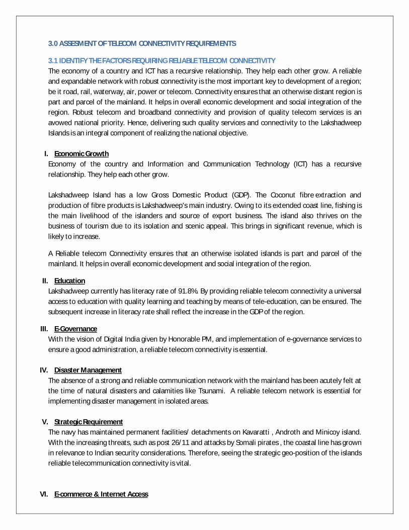
3.1 IDENTIFY THE FACTORS REQUIRING RELIABLE TELECOM CONNECTIVITY The economy of a country and ICT has a recursive relationship. They help each other grow. A reliable and expandable network with robust connectivity is the most important key to development of a region; be it road, rail, waterway, air, power or telecom. Connectivity ensures that an otherwise distant region is part and parcel of the mainland. It helps in overall economic development and social integration of the region. Robust telecom and broadband connectivity and provision of quality telecom services is an avowed national priority. Hence, delivering such quality services and connectivity to the Lakshadweep Islands is an integral component of realizing the national objective.
I. Economic Growth Economy of the country and Information and Communication Technology (ICT) has a recursive relationship. They help each other grow. Lakshadweep Island has a low Gross Domestic Product (GDP). The Coconut fibre extraction and production of fibre products is Lakshadweep's main industry. Owing to its extended coast line, fishing is the main livelihood of the islanders and source of export business. The island also thrives on the business of tourism due to its isolation and scenic appeal. This brings in significant revenue, which is likely to increase.
A Reliable telecom Connectivity ensures that an otherwise isolated islands is part and parcel of the mainland. It helps in overall economic development and social integration of the region.
II. Education Lakshadweep currently has literacy rate of 91.8%. By providing reliable telecom connectivity a universal access to education with quality learning and teaching by means of tele-education, can be ensured. The subsequent increase in literacy rate shall reflect the increase in the GDP of the region.
III. E-Governance With the vision of Digital India given by Honorable PM, and implementation of e-governance services to ensure a good administration, a reliable telecom connectivity is essential.
IV. Disaster Management The absence of a strong and reliable communication network with the mainland has been acutely felt at the time of natural disasters and calamities like Tsunami. A reliable telecom network is essential for implementing disaster management in isolated areas.
V. Strategic Requirement The navy has maintained permanent facilities/ detachments on Kavaratti , Androth and Minicoy island. With the increasing threats, such as post 26/11 and attacks by Somali pirates , the coastal line has grown in relevance to Indian security considerations. Therefore, seeing the strategic geo-position of the islands reliable telecommunication connectivity is vital.
VI. E-commerce & Internet Access

There is an increasing trend of commercial activity and connectivity over mobile phones which requires high bandwidth for making electronic commerce (e-commerce) transactions and access to social media connectivity through internet access.
3.2 ESTIMATION OF TELECOM BANDWDITH REQUIREMENT IN LAKSHADWEEP Vision Socio –Economic Growth Prior to assess the bandwidth requirements of Lakshadweep islands, it is essential to study the growth of other such islands groups like Mauritius. Mauritius: Mauritius is an island nation, located in the south-western Indian Ocean. The Republic of Mauritius is situated off the African coast in the Indian Ocean. Mauritius has a total area of about 2,040 square kilometers (787 square miles) and a population of about 1,291,456.
The rapid development and convergence of information and telecommunications technologies gave rise to an ICT industry on the island along with many incentives provided by the government. The government thus aims to make the ICT sector the 5th pillar of the Mauritian economy and Mauritius a Cyber Island
Mauritius is connected to Asia, Africa and Europe through multiple submarine cables. It can be seen that availability of reliable telecom connectivity can lead to overall growth in every aspect of that region.
Similarly, if a reliable telecom connectivity is provided in Lakshadweep the growth of ICT industry may increase and shall lead to overall development of Lakshadweep. BANDWIDTH ASSESSMENT The future bandwidth requirements have been assessed for all the inhabited islands of Lakshadweep with the objective of digitizing the entire island group. To assess the need of submarine OFC connectivity in islands, a detailed bandwidth projection for the next 10 years has been done. The customers for bandwidth usage have been categorized broadly in five to six categories as detailed below:
1. Mobile Backhaul As per the current trend in India, Broadband subscribers on mobile phones are the major contributors in broadband growth. To assess the bandwidth on mobile phones, the backhaul requirement of mobile towers / BTS is analyzed. It depends on the technology i.e. 2G, 3G or LTE with minimum backhaul requirement from 2Mbps to 30Mbps respectively. The TRAI report on Lakshadweep has indicated that total 26 BTS are required to provide coverage in Lakshadweep. To estimate the mobile backhaul providing 3G/LTE coverage in Lakshadweep for broadband services on mobile, the bandwidth requirement per cell site in increased from 12Mbps in initial years to 60 Mbps over a period of 15 years.
2. Household Broadband Penetration To estimate the broadband penetration in household, population data and decadal growth rate
of Lakshadweep was analyzed. It is seen that in past few decades the decadal growth rate of population in Lakshadweep is decreasing.

The average household size in Lakshadweep is 5.6 as per census 2011 data.The numbers of household in various years are estimated using above data.
The penetration of broadband connections shall increase gradually. To estimate bandwidth requirement per house hold, a 2Mbps link with a contention ratio of
1:10 is taken. This is as per National broadband Plan, which envisages a broadband connection of 2Mbps per household with contention ratio of 1:10.
3. Tele-Education & Tele-Medicine The Lakshadweep islands have around 15 school including 3 colleges and around 9 medical centers including hospitals, community and primary health centers. It is important to provide broadband connectivity to these educational and medical institutes located in the isolated islands to ensure quality delivery of education and medical expert opinion. A high Definition (HD) video streaming live session from mainland to these institutes takes around 4 to 5Mbps. Starting with 8 Mbps provision of 2 sessions and gradually increasing the bandwidth to 30 Mbps over a period of 15 years is considered for bandwidth projections.
4. Banks Presently there are around 9 banks operating in Lakshadweep and they need bandwidth for connecting to their branches in mainland and making financial transactions. The bandwidth requirement per bank is taken as 8 Mbps in initial years increased to 30 Mbps in 15 years.
5. Gram Panchayats (GP) There are 11 Gram Panchayats in Lakshadweep. The Gram Panchayat offices as per BBNL mandate also need to have broadband connectivity. A GP is provided a connectivity of 4Mbps increasing to 16 Mbps in 15 years.
Bandwidth Projected The total bandwidth in Lakshadweep is the summation of bandwidth required assessed under various categories. A graph indicating the bandwidth growth over the years is shown below.
0
20000
40000
60000
80000
1 2 3 4 5 6 7 8P 9P
Year
Population (no.)
0.0
2.04.0
6.0
8.010.0
12.0
1 2 3 4 5 6 7 8 9 10 11 12
Band
wdi
th (G
bps)
Year

The bandwidth assessment is made for 2 to 3 years from now, assuming a source of reliable telecom connectivity in Lakshadweep by that time.
It is seen that Bandwidth requirement of the islands is exponentially increasing from 1.7Gbps to 10 Gbps in 15 years which is understandable as the telecom market in Lakshadweep is in initial stage of development.
ISLAND-WISE POPULATION AND BANDWIDTH
The projected bandwidth for the entire Lakshadweep is divided among islands in proportion to their population. Island wise population and Bandwidth requirements
S.No. Island Population-
2011
Population (%)
Estimated Bandwidth (Mbps)
2019 2020 2022 2025 2030
1 Kavaratti 11221 17% 296 338 563 963 1781
2 Androth 11191 17% 295 337 562 961 1777
3 Minicoy 10447 16% 275 315 525 897 1659
4 Amini 7661 12% 202 231 385 658 1216
5 Agatti 7521 12% 198 227 378 646 1194
6 Kalpeni 4419 7% 116 133 222 379 702
Sub-Total (1-6) 52460 81% 1382 1581 2634 4504 8329
7 Kadmat 5404 8% 142 163 271 464 858
8 Kiltan 3946 6% 104 119 198 339 626
9 Chetlat 2347 4% 62 71 118 201 373
Sub-Total (8+9) 6293 10% 166 190 316 540 999
10 Bitra 271 0.42% 7 8 14 23 43
11 Bangaram 45 0.07% 2 2 2 4 7
Sub-Total (10+11) 316 0.49% 8 10 16 27 50
Total 64,473 100% 1699 1945 3238 5535 10236
Table 8: Projected Bandwidth
It may be noted that the above projected bandwidth is on a conservative side and as per the current trend of 4 G services; more bandwidth requirement can be expected in future. In any case, minimum one fiber pair shall be required which can carry as much as 14.4 Tbps traffic capacity with the present submarine technology available.

4.0 Submarine Optical Fiber Communication System
4.1 About Submarine OFC System Submarine cables are laid on the sea bed between land-based stations to carry telecommunication signals. They offer highly secure, reliable and very high capacity telecommunication links between countries across the world. The transmission quality of a sub-marine cable is significantly better than a typical satellite media. Submarine cables are only a few inches thick and they carry only a few optical fibers. Yet they have transmission capacities of the order of terabits per second (Tbps). However, a typical multi-terabit, trans-oceanic submarine cable system costs several hundred million dollars to construct A typical submarine cable system consists of
(i) A submarine cable system in the sea-bed [Wet Plant] and (ii) Terrestrial cable, Beach Manhole (BMH) and cable landing station (CLS) at land [Dry Plant]
The Wet Plant of a submarine cable system lies between the beach manholes, consists of submarine cable, repeater/gain equalizer, branching unit. The Dry Plant of a submarine cable system is a segment between the beach manhole and the cable landing station comprises of land cable, power feeding equipment (PFE) and submarine line terminal equipment (SLTE), etc. A typical schematic of a submarine cable system is shown below:
Figure 3: Submarine System Components
The submerged plant considered comprises of the cable for transmission, repeaters to amplify the signal at regular intervals, equalizers to maintain equal power in each signal channel, and branching units to enable network connectivity and flexibility. Associated with the submerged equipment is power-feed equipment, which is located at the terminal stations. The operating environment of the submerged plant places great demands on its mechanical design. In addition to requirement for mechanical strength against external water pressure, the equipment housing must protect the interior atmosphere against gas ingress. The target for the reliability of the submarine plant is that no more than one ship repair should be needed during that lifetime per two fiber pairs on a transatlantic cable. Such high reliability is ensured by design, with the use of high-reliability electronics and application of redundancy for components that display higher failure rates, together with strict quality procedures in the selection, testing, bum-in, and documentation of components and the use of ultraclean fabrication facilities.

4.1.1 Wet Plant Components Submerged Wet plant consists of all the equipment under the sea including submarine cable, repeaters, branching unit, equalizers, etc. It includes the submarine cable upto the Beach Manhole (BMH), including the Beach Manhole itself and the joint inside the BMH, it also includes the earthing and its cabling upto the BMH. The main characteristics to be considered while designing the wet plant shall be:
Proposed submarine cable features strong protection against external aggressions owing to its steel vault and armors.
Proposed repeaters are designed for long distances and wideband applications.
Proposed submerged equipment are fully accessible and operable by the network management system which provides monitoring facilities for preventive maintenance of the cable system.
a) Cables The cable has the primary objective to protect the fibers from the external world and to provide a means to connect the terminal stations through the wet-plant equipment. The cable is also in charge of carrying the power to the submerged equipment. The design of modern optical submarine repeatered cables concentrates on providing a stable low-loss optical transmission path, a power-feeding conductor for the submerged amplifiers, and sufficient strength and robustness to facilitate safe and successful installation operation and, if necessary, repair. The key fiber attribute in many wavelength-division multiplexing transmission systems is the attenuation of the optical fiber, which determines the amplifier or repeater spacing and is a key consideration in system design and cost. The Submarine optical fiber cable is laid connecting the terminal nodes between from the beach manhole of one node at the shore end on the sea bed. There are various types of submarine fiber cables depending on the protection layer provided on them.
Figure 4: Types of submarine cable (different levels of protective layers)
i. Type of armor
• Armor wire (LWA, SA, DA, RA, etc.) • Metallic screen/strengthen jacket (LWP, LWS, SPA, etc.) • Armoring post cable manufacturing • Duct, articulated pipe, etc.
A cross section of the shore-end of a modern submarine communications cable. 1 – Polyethylene 2 – Mylar tape 3 – Stranded steel wires 4 – Aluminium water barrier 5 – Polycarbonate 6 – Copper or aluminium tube 7 – Petroleum jelly 8 – Optical fibers

The cable for the entire route consists of combinations of sections of different kinds of cable connected together depending upon the water depths and sea-bed conditions. The difference comes in the form of armoring made around it. While shallower sections are more heavily ‘armored’ the deep-water cable is least ‘armored’. These are further defined and referenced as per ITU-T recommendation in the technical specification chapter related to submarine cables.
Figure 5: Details of Armouring in Submarine OFC The level of armoring is increased in case of shallow water where the chances of fiber cut due to man-made activities like anchoring etc is more.
The Submarine fiber laid shall comply with suitable ITU-T G.654/G.655/656 for submarine cable meeting the overall connectivity requirements.
The design life of the cable should be at least 25 years.
The submarine OFC type i.e. armored and non-armored shall depend on the depth from the seabed. The same is determined after conducting a Desktop Study and then confirmed through a Marine Survey which is carried out by the implementing agency. A general criteria for selecting fiber depending on depth of water is tabulated below:
Type Of Submarine OFC Water Depth Down(in sea)
Light weight (LW) 8000 meters Light Weight Protected (LWP) 1500 to 3000 meters
Single Armored (SA) 1000 to 2000 meters Double Armored (DA) 400 meters Rock Armored (RA) 200 meters
Table9: Type of OFC laid vis-à-vis Water Depth
ii. The type of fiber to be laid varies with the depth of the seabed. Factors of armor selection:
• water depth for a cable recovery • threat and hazard • what burial possible
burial depth (level of requirement and achievement) burial method, tool soil condition
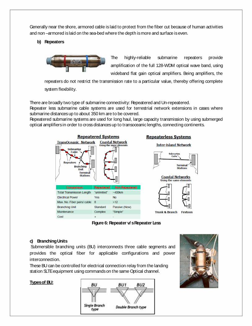
Generally near the shore, armored cable is laid to protect from the fiber cut because of human activities and non –armored is laid on the sea-bed where the depth is more and surface is even.
b) Repeaters
The highly-reliable submarine repeaters provide
amplification of the full 128-WDM optical wave band, using
wideband flat gain optical amplifiers. Being amplifiers, the
repeaters do not restrict the transmission rate to a particular value, thereby offering complete
system flexibility.
There are broadly two type of submarine connectivity: Repeatered and Un-repeatered. Repeater less submarine cable systems are used for terrestrial network extensions in cases where submarine distances up to about 350 km are to be covered. Repeatered submarine systems are used for long haul, large capacity transmission by using submerged optical amplifiers in order to cross distances up to transoceanic lengths, connecting continents.
Figure 6: Repeater v/s Repeater Less
c) Branching Units Submersible branching units (BU) interconnects three cable segments and provides the optical fiber for applicable configurations and power interconnection. These BU can be controlled for electrical connection relay from the landing station SLTE equipment using commands on the same Optical channel. Types of BU:

1. Passive BU – The Electrical connections/branches can’t be switched or controlled from Station & it is
electrically passive & doesn’t consume any electrical power. Also it is optically passive, means no Adding/Dropping of Wavelengths among three legs.
2. Power Switched BU – This type BU provides controllable electrical connections among the three
cable legs, as well as to the sea-ground electrode built into the trunk leg cable termination. The electrical connectivity within the 34A-Type BU is controlled on a powered system by means of an optical command signal & it will have a command receiver.
3. Power Switched OADM BU – It is similar to Power switched BU, but having optical add/drop
functionality using an OADM inside the BU, which makes it optically & electrically controllable among three legs.
4. Non-power switched BU – It is similar to Passive BU, but having OADM functionality.
d) Passive Equalizer Units (PEU) Passive Equalizer Units (PEU) are inserted in a submarine optical fiber cable to equalize the wavelength-dependent loss across the DWDM waveband, thereby improving the quality of transmission across a long cable. The gain equalization process is purely passive, using separate passive optical devices for each fiber. Gain equalizer function is needed for every 5-10 spans depending on the total length of the system. It is required because of non-flat nature of EDFA amplifier to compensate the gain which results with wider range of wavelength for traffic. It is basically optical filter which cleans up residual ripple and tilt from concatenating large number of EDFA’s.

Figure 7: Equalizer
e) Beach Manhole (BMH) BMH is a manhole near the sea shore where submarine fiber cable terminates and power and fiber separates. After this land cable and power cable are connected to fiber and copper conductor respectively which are extended to the cable landing station. Beach manhole is a special secured concrete chamber located on the beach (below the ground) where the submarine cable is landed on the ground. After the cable enters the BMH, through the slip hole made on the lower side of the seaward wall, its protective covering is stripped and clamped on the wall. The fiber and power conductors from the un-armored cable are then separated and by means of a special beach joint are separately connected to a land and earth cable coming from the cable landing station. The side-wall, adjacent to the one having the entry slip hole, has got four clamps adequately distanced allowing sufficient spare length of submarine cable to be coiled inside the BMH and also hold the beach joint. The BMH should be secured by means of a locking arrangement, in order to keep it out of reach from anyone other than the authorized maintenance staff. Care should also be taken that the location of the BMH on the beach is so chosen that the shore currents do not wash away the beach sand and over a period of time expose the BMH walls to the sea waves thus leading to a potential threat of the BMH getting collapsed or washed away. The sea earth (or ocean ground) is usually provisioned near the BMH, on the beach. These days most of the suppliers use the earthing electrodes (4-8 numbers) instead of one large circular earth plate. Depending upon the electrode security on the beach (in future from any potential construction activity) and also the soil resistance or cable length resistance, the earthing electrodes can alternatively be installed in the proximity of cable landing station or any other suitable area. The BMH construction usually falls within the cable owner’s responsibility like other civil constructions - cable station and land route. The BMH construction can be commenced once the CRZ clearance and permissions from relevant agencies (local municipality, beach land owning agency etc.) is available. The BMH dimensions are typically 3m x 3m x 3m.
The criteria for selection of potential suitable Beach Manhole (BMH) sites are:

• Proximity to CLS • Basic considerations
• Natural Factors • Human Impacts • Engineering Requirements
• Accessibility • Possibility of Interference with existing facilities • Impact of Fishing, Shipping and Future development • Ease of installation and maintenance • Impact of Overall cable route
4.1.2 Dry Plant a) Terminal Equipment
The CLS has the terminal equipment in it, which broadly consists of
Submarine Line Terminating Equipment Cross connect equipment (which is OTN based generally these days) Power Feed Equipment (PFE) for the repeatered cable
In addition to this, there is Network Management System (NMS) and accessories like ODF for patching the optical fiber.
Figure 8: Point to point Submarine Cable Link
i. Cable Termination Box (CTB): also known as Beach joint Box. It is placed inside the Beach manhole, and is a jointing box where submarine cable terminates and connects to the land cable. The land joint is a dry-plant component designed to allow the connection between the sub-sea cable and the terrestrial cables in the beach manhole at landings of undersea transmission systems, and the connection of combined optical/electrical cables on land routes between beach manholes and terminal stations.

Figure 9: Land Joint installed in Beach manhole (Courtesy: ASN)
ii. Cable Termination Rack (CTR): The CTR is used for terminating the cable in the landing stations
of an unrepeatered segment. The cable enters either via the top or the bottom of the rack, and is secured in a cable-terminating manifold from where the individual fibers inside the cable are taken to an Optical Fibre Distribution unit. In the fiber distribution unit fibers from cable are spliced to fibers going to the SLTE. The CTR usually also comprises a cable testing & monitoring facility, and electrical testing (electroding) functions. One CTR can also be used to terminate two cables.
iii. Line Terminal Equipment (LTE): It comprises of all equipment in a terminal station including SLTE, Power Feeding Equipment (PFE), maintenance Controller (MC), internal ODF.
iv. Submarine Line Terminal Equipment (SLTE): It is used to combine all incoming optical signal(s) into optical output after adapting for transmission over the submarine cable and perform the reverse operation in the opposite direction.
The fiber from the CTR would be terminated into one submarine Line Terminal Equipment (SLTE) at each side.
4.2 Capacity of Submarine OFC links The submarine cable systems have evolved from 1994 to present as can be seen from the diagram below. A single optical fiber can carry upto 80 wavelengths with each wavelength (lamda) being able to carry 100 Gbps (4th Gen.) of data which makes the capacity of a single optical fiber 8 Tbps. 100Gbps per lambda systems are commercially available and being deployed globally. Evolution of Capacity:

Courtesy: NEC
Figure 10: Evolution of Submarine Equipment Technology
As seen above , currently the system are evolved to work on 100Gbps DWDM systems and future technologies of upto 400Gbps are forecasted by manufacturers. The next phase of evolution is the Super Channel (5th Gen.)
Courtesy: NEC
Figure 11: Channel Spacing in a Submarine System In this regard, the capacity of the existing submarine cables landing in India was also analyzed. It was found that mostly the current working system are upgraded to 100Gbps and the new upcoming are designed for digital coherent 100 Gbps technology. The figure below gives a snapshot of cable landing in India, Indian Telecom owners, associated technology upgrade and fiber pair.
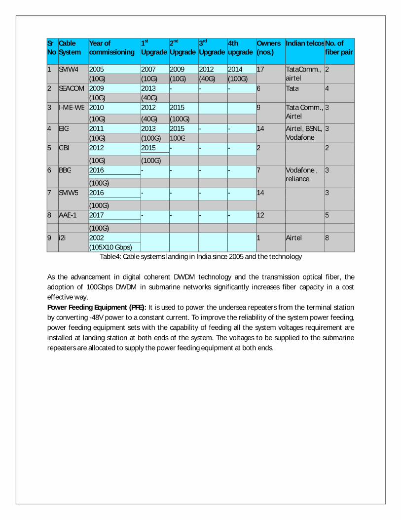
Sr No
Cable System
Year of commissioning
1st Upgrade
2nd Upgrade
3rd Upgrade
4th upgrade
Owners (nos.)
Indian telcos No. of fiber pair
1 SMW4 2005 2007 2009 2012 2014 17 TataComm., airtel
2 (10G) (10G) (10G) (40G) (100G)
2 SEACOM 2009 2013 - - - 6 Tata 4 (10G) (40G)
3 I-ME-WE 2010 2012 2015 9 Tata Comm., Airtel
3
(10G) (40G) (100G) 4 EIG 2011 2013 2015 - - 14 Airtel, BSNL,
Vodafone 3
(10G) (100G) 100G 5 GBI 2012 2015 - - - 2 2
(10G) (100G) 6 BBG 2016 - - - - 7 Vodafone ,
reliance 3
(100G) 7 SMW5 2016 - - - - 14 3
(100G) 8 AAE-1 2017 - - - - 12 5
(100G) 9 i2i 2002 1 Airtel 8
(105X10 Gbps) Table4: Cable systems landing in India since 2005 and the technology
As the advancement in digital coherent DWDM technology and the transmission optical fiber, the adoption of 100Gbps DWDM in submarine networks significantly increases fiber capacity in a cost effective way. Power Feeding Equipment (PFE): It is used to power the undersea repeaters from the terminal station by converting -48V power to a constant current. To improve the reliability of the system power feeding, power feeding equipment sets with the capability of feeding all the system voltages requirement are installed at landing station at both ends of the system. The voltages to be supplied to the submarine repeaters are allocated to supply the power feeding equipment at both ends.

Courtesy: NEC paper
Usually each of the two landing stations feeds both positive and negative voltage corresponding to ½ of the total system voltage. If a fault occurs in either of the power feeding equipment, the one at the opposite landing station feeds the total system voltage in order to enable a constant current supply to the submarine repeaters. This system redundancy is intended to improve the system reliability.
A PFE usually comprises of 3-4 racks and consists of following main units
Power converter units to convert the low voltage DC to the very high voltage DC needed to power the submarine cable at a constant current. Number of converter units needed is as per power voltage rating of the PFE, which in turn is dependent upon segment length. A spare converter unit is usually part of PFE .
A Dummy Load for offline testing of the PFE to avoid any damage to the wet plant Control unit from where the PFE functions are monitored and controlled. Duplicated control
units are provided within the PFE Cable Terminating Equipment for interconnecting the submarine cable, the System Earth and
the dedicated Station Earth

As the PFE handles high voltage, the PFE racks are secured by closed doors and several key arrangements. Any attempt to gain access to cable or HV units would lead to an automatic PFE shutdown causing the traffic outage on the segment. The size of the PFE (number of racks) is dependent upon its rated current and voltage output, which is in turn dependent upon segment length and is achieved by adding more converter units in series. Usually 4-5 rack space is required for a duplicated 6kW PFE. PFE racks are not standard 600mm dimensioned but slightly larger.
v. Internal ODF: This is Optical distribution Frame (also known as FDF) where the cable interfaces
is terminated and where the SLTE is connected to the SIE.
vi. Maintenance Controller (MC): The MC is used to supervise the SLTE, the PFE and the submerged plant from a human computer interface. The MC shall be there in each terminal station and shall allow quick localization and trouble shooting. The wet plant supplier will provide a Maintenance Controller (MC) in 1+1 configuration for managing the SLTE of the entire network. The Maintenance controller would comprise of servers and workstations and have a centralized architecture. At every landing station, a Local Craft Terminal (LCT), which is usually a laptop would be available separately for SLTE and SIE for local access and trouble shooting of the equipment along with a spare.
Both the MC and NMS servers would be located at the main NOC and back-up NOC locations. The BNOC would be a hot standby of the NOC servers and would act as a disaster recovery center (DRC).The NOC team would manage the cable system network through the MC and NMS workstations.
The connection of all nodes (equipment) of all landing station to MC and NMS servers and workstations would by via a DCN (data connection network), which would be provisioned through e-1 overheads of the transponder. The nodes correspond with the server usually on a TCP/IP protocol.
The DCN would also be used to provide the IP / EPABX based order wire between the NOC and cable landing stations.
A reliable DCN link is essential to provide continuous visibility of the network to the NOC. A cable fault would however mean the isolation of the one side of the network for which a 2Mb satellite link would be needed to act as ADCN link.
vii. OTN (Optical Transport Network) based Interconnection Equipment: OTN technology was designed to provide support for optical networking using WDM unlike its predecessor SONET/SDH. OTN is also called digital wrapper or optical channel wrapper. The wavelengths (lambdas) being received from the line side on a single optical fiber are demultiplexed into individual lambdas and then the transponder converts the optical signal into electrical signal. The 100 Gbps electrical signal can be further broken down into its client signals of 1/10 Gbps by means of an OTN based cross connect equipment. The cross connect would provide the add/drop and cross-connect functions for terminating traffic in a landing station. The 10G client

signals from SLTE would be terminated on the cross connect equipment and can be cross connected to several lower order ports as per customer needs at any landing site. It comprises of all the equipment which provides interconnection between adjacent line segments and the domestic network in a terminal station including Network Elements (NEs), Element Management Systems (EMS), Network Management system, External ODF, data communication network associated with IE. It may also include the human computer interfaces that may be located outside the terminal station and connected to the management system through the external network and used to supervise the system.
viii. External ODF: It is ODF/FDF where system interface is terminated and where the SIE is connected to the terrestrial equipment (SDH-64 etc.)
ix. Network Synchronization: For Lakshadweep system, if existing BSNL network is not having stratum 1 Primary Reference Clock source (already feeding less than 20 units) at Kochi to synchronize cable network also, then a separate PRC source would need to be installed in 1+1 mode at Chennai and Port Blair for providing network synchronization.
The G.811 level PRC source comprises of a GPS receiver (small antenna and modular unit) that connects through a SSU to multiple network elements.
The synchronization network would be supplied, configured and installed by the main system supplier.
x. Network Management: The Network management will be made of two components : a) A redundant maintenance controller (MC) dedicated to the management of the submarine
part of the system based on two software applications: o Element Manager – it integrates information from the submarine network elements of
the system (i.e. SLTE and PFE). The submarine optical path manager allows the supervision of the offered submerged plant as well as the end to end wavelengths and network powering configuration.
o Network Manager at terminal station. It may also be located outside terminal station at a central place.
b) The NMS functions are broadly as below:
Performance Management
Fault Management
Configuration Management
Security Management xi. Data Communication Network: The Data Communication network (DCN) is a dedicated system
supporting the communications between the network elements (e.g. SLTE, PFE etc.) and Network Management elements (e.g. Servers and Operator Positions) for all landing sites.
xii. Network Protection: For traffic protection, it is planned to implement the following protection schemes through the SDH equipment between SDH and SLTE:
Multiplex Section Protection (MSP) 1+1 (from day 1 equipage): to provide protection against transponder failure
Sub-Network Connection Protection (SNCP): to provide path level protection for specific users

MSP 1+1 configured on the DLS terminating ports of the 2 fiber pairs on the SDH equipment would provide the multiplex section protection. Thus it will provide protection against traffic interruption on one fiber pair due to any reason between the two SDH equipment of the segment, including a transponder failure. Due to MSP protection, the traffic would automatically get routed through the other fiber pair of the segment and would thus avoid any interruptions.
As with increase of traffic, more 10G get commissioned, it could be configured in MSP through a vacant 10G on the other fiber pair. Whenever the transponder failure rate reduces to low levels, the MSP 1+1 could be modified into MSP 1+n for effective utilization of equipment.
The SNCP protection would provide a dedicated path level protection to specific users who require protection against any transponder failure scenario. SNCP could be used when all traffic terminating in a station need not be protected and the protection facility is to be provided only to specific users. SNCP and MSP must be used independent of each other. The two protection schemes, MSP & SNCP, configured through SIE provide for an efficient and complete way of traffic protection including against transponder failures. It is a suitable and more efficient way of traffic protection popularly deployed across cable systems for long.
The detailed specifications of above system components are given in Chapter 5.
Terrestrial Cable including Trenches
The terrestrial land cable shall connect the submarine cable terminating in a cable termination box in Beach Manhole to the Cable landing station equipment. The land cable route from the BMH to the landing station needs to be prepared by the cable owner. Its construction is undertaken along with the BMH construction after relevant approvals are in place.
The usual practice for constructing land route is to use 110mm (OD) HDPE, in a concrete encasing, covered with soft soil and warning tape at usually 1.5 m depth. Hand holes at regular intervals need to be provided for ease of cable pulling. The distance and size of hand holes are usually dependent upon how many ducts are to be laid and for what length (cable station to BMH).
Depending upon the land cable type to be used (sometime its similar to submarine cable, other times the power cable is separated) one main duct with sub-ducts or two separate main ducts could be used for landing one segment cable. If there are more than one segments planned through one common land route, its preferred to use sub-ducts, in order to keep distinction easy for repair team during repairs.
Cable Landing Station (CLS)
The CLS is a building containing the onshore end of the submarine cable and equipment for connecting to backhaul circuits.
i. Consideration of Cable Landing Station:
Floor space for terminal equipment, facilities and office for maintenance staff, etc Connectivity to back haul network Access for construction and future maintenance Approach to the cable landing site Land cable route

Electronic/magnetic interference ii. Suitable for cable landing/installation operation
Cable laying ship can easily access to the beach
Access for beach works and usage of heavy machinery
Seabed topography, material and condition
Close parallels/crossing to other cables, pipelines
Low risk of fishing activity, anchoring, dredging, mining
Regulation, permission issues
National park, coastal reserves, etc
There can be more than one prospective Cable landing station sites considering the above factors.
Cable Landing Station Construction Practices
Once the selection of the landing station site has been made by the cable owner, the landing station itself would need to be planned. For maintaining communication redundancy, landing stations of two cable systems are preferably not planned within one complex or building.
The main parameters that go into the planning of cable landing station are: Provision for an equipment room Provision for utilities room and open space for generators
Provision for Dual source AC grid power into the equipment room (cable vault, if necessary)
Provision for station earth
Provision for cable Station infrastructure (mentioned in next section) The equipment room should in general provide a secured and direct access of the cable to the equipment room and easy movement and installation of the equipment should be possible. If the equipment room is planned on a multi-level building, the load factor of all the equipment required to be installed on that level (for design capacity) need to be kept in to consideration.
The utility arrangements and the site-space most often vary from one landing station site to another. Hence a lot of customization is required in planning the equipment floor for any given landing station site. Part of utilities (Electric panels, DCDB, AC units) sometimes are already available in a common floor and cannot be installed in the equipment floor space and other times, they might necessarily be needed to be installed at the equipment floor space due to constraints elsewhere. Similarly, the balance between length and width of the equipment floor could be achieved by efficiently performing the interplay between number of rows, racks per rows and placement of equipment types. The transmission equipment types also sometimes differ from supplier to supplier and determine the installation arrangement (eg. front and back opening, back-to-back installation possibility, heat dissipation areas etc)
As an example, the typical floor space requirements in cable landing stations enabling standard installation practices for following two cases of rack/row arrangement are shown below:

Equipment layout arrangement Dimension (meters)
Equipment floor area with 2 equipment rows accommodating 6 standard racks per row – 3 rows operating width
4.8 x 6.6
Equipment floor area with 3 equipment rows accommodating 6 standard racks per row – 4 row operating width
6.6 x 6.6
Workstation area 3 x 3.5
Utility area 4.2 x 7.5
Table10: Landing station equipment installation dimensions
Thus depending upon the site conditions - space and utility arrangement, and once the specifics and make of transmission and utility equipment are known, the precise equipment floor dimensions could be worked out (for design capacity).
Secondly, like any other central transmission hub or gateway - where large amount of communication traffic of the region is concentrated, adequate measures of safety and protection need to be ensured. These may include Security against tress-passing and sabotage Effective resistance against natural hazards such as earth-quake, flooding, strong wind, rain,
lightning and fire.
Safety provision planned for these parameters are usually governed by the existing situation and facilities at the chosen site and require detailed analysis at every site. While general standards of security are followed as a minimum, often a lot of customization is required here also to keep the risks to minimum under the prevailing situation.
Thirdly, the developments of facilities at a cable landing station are also often driven from business and commercial perspective of the telecommunication infrastructure (and bandwidth) going to be available at the cable system. Since the submarine cable for effective commercialization is required to be used by many telecom operators, hence provision should be available that these telecom operators have convenience of building their networks up to the cable landing site and a standard inter-connection facility exists.
These may include;
Provision for meet-me room for other telecom users and backhaul providers International datacenter level infrastructure for meet-me room Provision for backhauling from meet-me room
As three to four distinct aspects are required to be considered while planning for cable landing station and several parameters of these aspects play an important role in determining overall utility of cable landing station, hence the planning is usually undertaken by a joint team of experts capable of ensuring specialized needs of all aspects - submarine project execution, submarine cable O&M, utility, civil and infrastructure aspects and meet-me-room infrastructure.
The cable landing station planning and development activities are usually commenced in parallel when the supply contract comes into force as the specifics of equipment, cable, footprint, power consumption

are by then finalized along with clarity of available space and resources and business plans. These activities usually go on for several months, evolving frequently as best suited option are continually explored and tried.
The timely readiness of cable station, land route and BMH within the deadline as included in the supply contract plan of work of the chosen supplier, is of utmost importance in order to not to have claims and delays from the supplier. With this view, it is also important that during the contract signature, while mutually agreeing the plan of work, adequate time for cable station and relate infrastructure readiness is carefully allotted and considered along with other related activities of the project supplier.
Infrastructure within the cable landing station
Other main infrastructure elements of a typical cable landing station are as following:
I. Power plant (-48V DC) This would include complete set up of SMPS, rectifier, battery bank and electric panels. The SMPS cabinet nowadays house AC distribution cabinets with control unit, DC Distribution cabinet with control unit, Rectifier rack with monitoring module and Rectifiers. Usually 2000 Amps SMPS scalable up to 4000 Amps are preferred for cable station needs.
II. DG sets for AC power back-up The DG set is proposed as emergency backup against failure of grid supply for network and power equipment like SMPS, Air- conditioning and Lighting. The generator will be sized to supply the transmission equipment load, the UPS (Un-interruptible Power Supply) in the ultimate configuration, air- conditioning and other utilities in the station and would be provided in a 1+1 configuration. Usually 20-25 kVA DG sets suffice for cable station needs.
III. Precision AC (PAC) Units
These are independent units capable of providing 0.80 to 0.90 sensible heat ratios for effective and efficient cooling required in equipment floors where movement of people is low.
IV. Fire detection, alarm & control system The laser based early warning smoke detection VESDA system is used as fire detection system. The VESDA panel shall be compatible to transfer the signals to Fire detection panel. FM200 Fire suppression systems are generally preferred for such needs The main advantage of FM200 fire suppression system is that they can reach extinguishing levels in 10 seconds or less, and require small amount of agent required to suppress a fire resulting in lesser space requirement.
V. Water Leak detection system Water leak detection control panel of 4 zone / 8 zone type consisting with features like, auxiliary alarm contacts, monitored alarm outputs, Open & short circuit line monitoring, Bright LED's for indication are typically used.
VI. Rodent Repellants The Rodent repellent Pest control system usually consists of Master Console capable of connecting to 12 Satellites, Satellite Units complete & Connecting Cables with conduits, junctions boxes and all accessories as required.
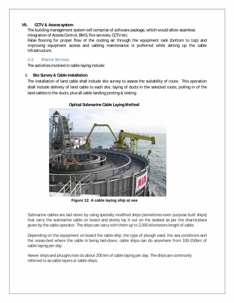
VII. CCTV & Access system The building management system will comprise of software package, which would allow seamless integration of Access Control, BMS, Fire services, CCTV etc. False flooring for proper flow of the cooling air through the equipment rack (bottom to top) and improving equipment access and cabling maintenance is preferred while setting up the cable infrastructure.
4.3. Marine Services The activities involved in cable laying include:
I. Site Survey & Cable Installation The installation of land cable shall include site survey to assess the suitability of route. This operation shall include delivery of land cable to each site, laying of ducts in the selected route, pulling in of the land cables to the ducts, plus all cable landing jointing & testing.
Optical Submarine Cable Laying Method
Submarine cables are laid down by using specially modified ships (sometimes even purpose built ships) that carry the submarine cable on board and slowly lay it out on the seabed as per the charts/plans given by the cable operator. The ships can carry with them up to 2,000 kilometers length of cable. Depending on the equipment on-board the cable-ship, the type of plough used, the sea conditions and the ocean-bed where the cable is being laid-down, cable ships can do anywhere from 100-150km of cable laying per day.
Newer ships and ploughs now do about 200 km of cable laying per day. The ships are commonly referred to as cable layers or cable-ships.
Figure 12: A cable laying ship at sea
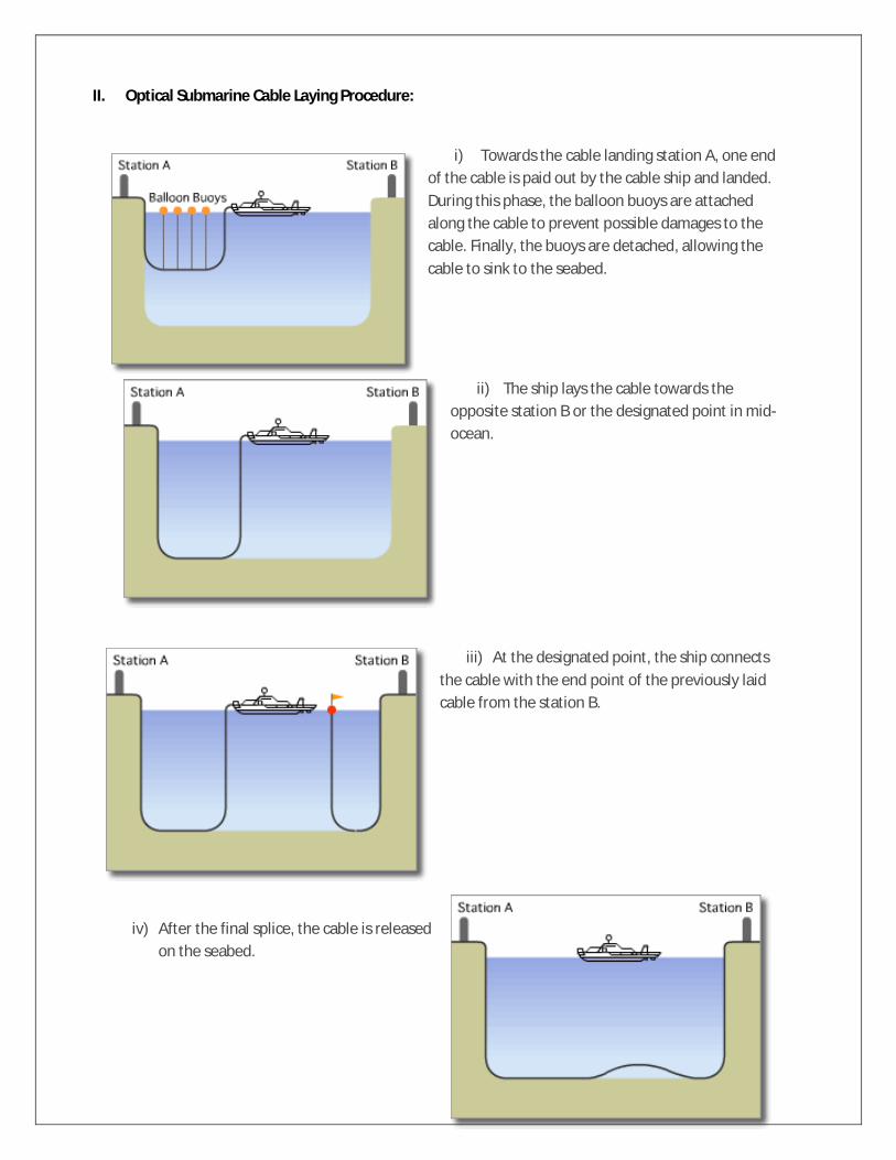
II. Optical Submarine Cable Laying Procedure:
i) Towards the cable landing station A, one end of the cable is paid out by the cable ship and landed. During this phase, the balloon buoys are attached along the cable to prevent possible damages to the cable. Finally, the buoys are detached, allowing the cable to sink to the seabed.
ii) The ship lays the cable towards the opposite station B or the designated point in mid-ocean.
iii) At the designated point, the ship connects the cable with the end point of the previously laid cable from the station B.
iv) After the final splice, the cable is released on the seabed.

III. Cable Terminations The land cable will be connected into the cable termination cubicle at the terminal station with the appropriate connections for system monitoring, safety etc. following the satisfactory landing of the shore end section of the land cable. This joint will be secured within the beach manhole.
IV. Power Feed Earth (PFE) PFE system at each of the landing locations will consist of an earth array (up to 8 electrodes) with a cable connection to the terminal station. Typically, the array will be installed at the beach, near the beach manhole and the connecting cable will be pulled into a sub-duct within the same duct as for the land cable. The electrodes to be installed within 25 meters from the BMH, and in sandy/ normal soil type conditions to a maximum depth of 4.0 meters. The protection of land cable is critical to ensure seamless working of the whole submarine system as any cut due to undesirable activity shall disrupt the whole traffic. As this land cable is jointed with submarine cable inside beach manhole with a lot of precision, diversification of land cable through another route to ensure redundancy is not feasible. Therefore, it is suggested to install sensors along the duct and CCTV cameras for 24*7 monitoring of land cable route.
V. Marine Operations and Maintenance
Optical Submarine Cable Repair Method There is a case in which an optical fiber cable is cut or damaged due to ocean earthquakes and fishing gears etc. In the situation, the cable ship is urgently dispatched to the cable failure site and repairs the cable. The cable repair procedure normally consists of the followings: 1) Localization of the cable failure point. 2) Recovery of the failure cable onto the ship 3) Cutting and removal of the cable failure section 4) Jointing of the recovered cable and the spare cable in the cable tank of the ship 5) Confirmation test and reburial of the cable
Optical Submarine Cable Repair Procedure:
1. The distance of the cable failure location from the landing station is estimated by several tests in advance. The cable ship is navigated to the location by DGPS. At the place, the tool for cable search and cutting, which is attached to the rope end, is paid out to the sea. By dragging the grapnel tool on the seabed, the cable is cut.

2. The rope with the grapnel at its end is paid out from the ship, and one end of the cut cable is caught by the grapnel (Cable Catch), and is recovered to the ship (Cable Recovery). It might take more than one day to recover the cable from the sea of 8,000m depth. The optical fiber test and electrical test of its power feed conductor is carried out. If there is still a failure, the cable is recovered further, the failure section is cut and removed.
3. At the end of the cable from which the failure section is removed, the waterproof treatment is carried out. After the attachment of the mooring rope and buoy to it, the cable is once dropped in the sea. The cable ship moves for searching the other end of the cable, and repeats the same procedure as above item
4. The optical fiber test and electrical test of its power feed conductor on the recovered cable is carried out in the same way as above item 2. If there is a failure, the failure section is cut and removed. The cable is jointed with the spare cable which is stored in the cable tank (normally, Universal Joint technology is used). The cable ship approaches to the previously installed buoy together with paying out the spare cable.
5. Holding the spare cable, the cable ship recovers the cable attached to the buoy again, and joints it with the opposite end of the spare cable. For the final confirmation, the test is held between two cable landing stations of the cable. After the confirmation of the communication normality, the on-board cable is released to the seabed, and the repair work is completed.

Fault isolation and repair There are two ways for optical fault isolation: 1. Optical Time Domain Reflectometer (OTDR) is a hardware device used for measurement of the
elapsed time and intensity of light reflected on optical fiber. The reflectometer can compute the distance to problems on the fiber such as attenuation and breaks, making it a useful tool in optical network troubleshooting. The intensity of the return pulses is measured and integrated as a function of time, and is plotted as a function of fiber length.
Figure 13: OTDR
2. Coherent Optical Time Domain Reflectometer (COTDR) is an instrument that is used to perform out
of service backscattered light measurements on optically amplified line systems. A fiber pair is tested by launching a test signal into the outgoing fiber and receiving the scattered light on the in-coming fiber. Light scattered in the transmission fiber is coupled to the incoming fiber in the loop-back couplers in each amplifier pair in a repeater.
Figure 14: COTDR
Maintenance Agency Submarine cable systems are designed for robustness and reliability during a 25-year lifespan. However, there is always the risk of damage from external sources. To help reduce the impact of cable outages, a periodical regular submarine cable maintenance services is required.
The ships and depots are strategically positioned so that they can arrive at a problem location as quickly as possible, equipped to perform any repairs.
Special fleet ships are manned by qualified, experienced teams and are strategically located to lay the fiber and maintain it. The cable ships are equipped with High engine power, thrusters and dynamic

positioning to maintain position and work in almost any weather conditions, High-tow force, heavy-duty ploughs for cable burial, Cable lay control systems. A Remotely Operated Vehicle (ROV) is used for installation and maintenance. Worldwide submarine cables are maintained by these special fleet ships and their regions are divided as shown in map below.
Figure 15: Maintenance Zone
4.4. Worldwide Cable Networks
Figure 16: Submarine cable network worldwide
General

Submarine Cable Networks Systems are categorized in accordance with their corresponding coverage as below: Trans- Pacific Submarine Cable Systems The first trans-Pacific submarine cable system, TPC-1 (Trans Pacific Cable 1), was put into service on June 19, 1964. It's a submarine coaxial cable linking Japan, Guam, Hawaii and mainland U.S.A. via Hawaii, with a small capacity of only 128 telephone lines. After that, many transpacific submarine cable systems were built continuously. Now, the in-service transpacific submarine cable systems include AAG, China-US CN, Japan-US CN, Pacific Crossing 1, Southern Cross Cable Network, Telstra Endeavour, TGN Pacific, TPC-5, TPE, Unity, etc. Trans-Atlantic Submarine Cable Systems Since the first transatlantic submarine cable system, TAT-1, went into service on 25 September 1956, there have been 26 submarine cable systems across the Atlantic Ocean. Most of the transatlantic submarine cable systems have been retired of communications service. Now, the in-service trans-Atlantic submarine cable systems include CANTAT-3, TAT-14, Apollo, Atlantic Crossing 1 (AC-1), Atlantic Crossing 2 (AC-2, also called Yellow), Columbus-III, FLAG Atlantic 1 (FA-1), Hibernia Atlantic, Tata TGN Atlantic. Trans-Atlantic submarine cable systems, including Hibernia Atlantic's Project Express and Emerald Atlantis, were ready for service by the end of 2012 or early 2013. Intra-Asia Submarine Cable Systems Intra-Europe Submarine Cable Systems Asia-Europe-Africa Submarine Cable Systems Australia-USA Submarine Cable Systems Asia-Australia Submarine Cable Systems Eurasia Terrestrial The Eurasia Terrestrial Cable Network is an important part of the global telecom infrastructure, consists of various terrestrial cable systems such as TEA, TEA-2, TEA-3, ERA, ERMC, EKA, CR2, etc., with the efforts and cooperation from carriers in China, Russia, Mongolia, Kazakhstan, and other Asian and European countries, the Eurasia Terrestrial Cable Network has been stable enough to offer bandwidth up to 10G or 10GE with SLA guaranteed. Brazil-US Submarine Cable Systems Brazil-Europe Submarine Cable Systems Brazil-Africa Submarine Cable Systems Europe-Africa Submarine Cable Systems Inter Asia submarine communication systems APCN APCN-2 EAC-C2C FNAL/RNAL TGN-IA MCS MIC-1 KJCN APG

ASE Cahaya Malaysia TIS DMCS BDM TSE-1 SeaX-1 Subsea Networks connecting India with other continents Stations There are now 10 submarine cable landing stations in India, with four in Mumbai, three in Chennai, and each in Cochin, Tuticorin and Digha.
Tata Communications owns three cable landing stations, each in Mumbai, Chennai and Cochin.
Reliance Globalcom owns the Versova Cable Landing Station in Mumbai. Bharti Airtel owns three cables landing stations, two in Chennai and one in Mumbai. Sify Technologies launched its cable landing station in Mumbai in January 2012. BSNL owns its first international submarine cable connecting India and Sri Lanka and
its cable landing station in Tuticorin. The Digha Cable Landing Station in West Bengal is newly approved in May 2011 by
the department of telecommunication (DoT) of India for a submarine cable project between India and South-east Asia.
BNSL is expected to own the Digha Cable Landing Station. Cables TIC TIC (Tata Indicom Cable), also known as TIISCS (Tata Indicom India-Singapore Cable System), is a submarine cable linking India and Singapore. The TIC cable spans 3,175 km, lands in Chennai, India and Changi, Singapore. Construction of the cable TIC began in November 2003 and went on live on September 15, 2004. The TIC cable system comprises of 8 fiber pairs, operates with 64x10 Gbps DWDM technology, with a design capacity of 5.12 Tbps. The TIC cable system is 100% owned and operated by Tata Communications. i2i In March 2001, SingTel and Bharti Group formed a 50:50 private submarine cable development company, Network i2i, for the construction of the i2i cable network (i2icn) which was the world's largest cable network in terms of bandwidth capacity (8.4 Tbps) then. The i2i submarine cable consists of 8 fiber pairs connecting Tuas cable landing station in Singapore and Chennai cable landing station in India, spans 3100 km. The entire i2i cable network utilizes the latest Dense Wavelength Division Multiplexing (DWDM) technology, with 105 wavelengths of 10 Gbps when fully equipped. BLCS The Bharat Lanka Cable System is a 320-km submarine cable systems connecting India and Sri Lanka. Initially it will have a capacity of 40 Gbit/s that will later be upgraded to 960 Gbit/s. WAC The West Asia Crossing (WAC) is an intra-Asia submarine cable system planed by Pacnet. The WAC connects India through a landing station in Chennai, to both Malaysia and Singapore. The WAC is

April 3, 2019 TCIL DPR on Lakshadweep Submarine Fiber Connectivity, Private & Confidential Page 51
also designed to offer the flexibility of extending connectivity into Bangladesh and Sri Lanka through separate branching units, as well as the possibility of a second cable landing point in Mumbai to offer additional capacity to cables landing off the west coast of India. ICX The India Cloud Xchange (ICX) subsea cable system is a private cable to be constructed by Global Cloud Xchange (former Reliance GlobalCom), delivering a direct Mumbai-Singapore route to bypass current outage prone terrestrial routes between Mumbai and Chennai. The ICX subsea cable runs approximately 5,060 kilometers between Mumbai and Singapore. Based on state-of-the-art 100G technology, the ICX cable is a four fiber pair system with initial design capacity per fiber pair at 80 x 100G. BBG The Bay of Bengal Gateway (BBG) is a new cable system that meets the continued bandwidth growth between the Middle East, the Indian sub-continent and South East Asia. The BBG cable lands in UAE, Oman, India, Sri Lanka, and Malaysia, with a diverse terrestrial network from Malaysia to the Singapore points-of-presence at Equinix and Global Switch
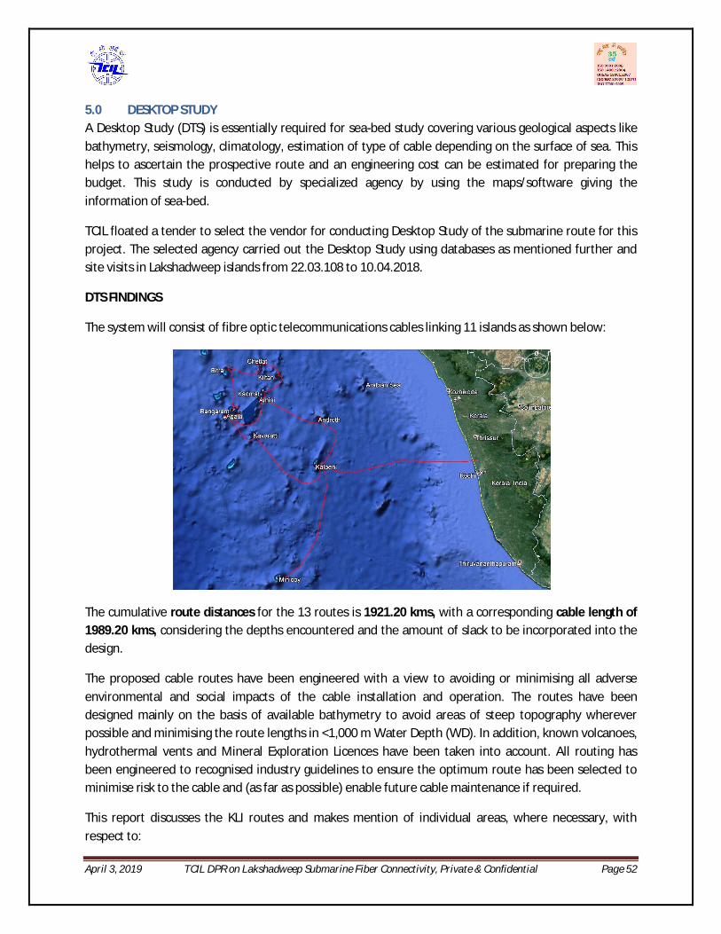
April 3, 2019 TCIL DPR on Lakshadweep Submarine Fiber Connectivity, Private & Confidential Page 52
5.0 DESKTOP STUDY A Desktop Study (DTS) is essentially required for sea-bed study covering various geological aspects like bathymetry, seismology, climatology, estimation of type of cable depending on the surface of sea. This helps to ascertain the prospective route and an engineering cost can be estimated for preparing the budget. This study is conducted by specialized agency by using the maps/software giving the information of sea-bed.
TCIL floated a tender to select the vendor for conducting Desktop Study of the submarine route for this project. The selected agency carried out the Desktop Study using databases as mentioned further and site visits in Lakshadweep islands from 22.03.108 to 10.04.2018.
DTS FINDINGS
The system will consist of fibre optic telecommunications cables linking 11 islands as shown below:
The cumulative route distances for the 13 routes is 1921.20 kms, with a corresponding cable length of 1989.20 kms, considering the depths encountered and the amount of slack to be incorporated into the design.
The proposed cable routes have been engineered with a view to avoiding or minimising all adverse environmental and social impacts of the cable installation and operation. The routes have been designed mainly on the basis of available bathymetry to avoid areas of steep topography wherever possible and minimising the route lengths in <1,000 m Water Depth (WD). In addition, known volcanoes, hydrothermal vents and Mineral Exploration Licences have been taken into account. All routing has been engineered to recognised industry guidelines to ensure the optimum route has been selected to minimise risk to the cable and (as far as possible) enable future cable maintenance if required.
This report discusses the KLI routes and makes mention of individual areas, where necessary, with respect to:
April 3, 2019 TCIL DPR on Lakshadweep Submarine Fiber Connectivity, Private & Confidential Page 53
Geology and Submarine Physiology (Bathymetry)
Offshore Activities and Potential Hazards
Oceanography and Meteorology
Landfalls and Engineering
Additional supporting information, which is not of immediate relevance to the text, is presented in the appendices. Sources of Data used for the DTS:
The sources of data consulted during the compilation of this report are:
Telecommunications cables OSAS Database
Pipelines Local knowledge and Database
Maritime Boundaries Global Maritime Boundaries Database
Oil and gas field structures Database and local knowledge
Future oil and gas exploration Infield Systems Limited data and local knowledge
Dredging and reclamation Charted or from local advice
Port developments Charted or from local advice
Near shore infrastructure developments Charted or from local advice
Fishing activities Web or from local advice
Shipping and associated anchorages Web, charted or from local advice
Marine parks Web or from local advice
5.1. Site Visit Findings The main findings of survey such as identification of cable landing sites (Cable landing station and beach manhole) and submarine cable route are covered in this chapter. For more details refer the Desktop study Report enclosed with this report.
The site visits have been conducted to all the islands and their beaches to identify the potential BMH locations considering all the factors as mentioned above. The detailed site visit of each island including the pictures and of Kochi is available in the DTS Report.
BMH Locations Table11: below summarizes the BMH locations used in the RPLs, as recommended based on the Site Visits.

April 3, 2019 TCIL DPR on Lakshadweep Submarine Fiber Connectivity, Private & Confidential Page 54
NAME STATUS LOCATION
Cherai, Kochi, Kerala Preferred option 10° 08' 26.7" N 76° 10' 43.4" E
Kalpeni Preferred option 10° 04' 00.00"N 73° 38' 52.60"E
Minicoy Preferred option 08° 16' 45.2" N 73° 03' 31.3" E
Androth Preferred option 10° 49’ 02.1” N 73° 42’ 01.1” E
Kavaratti Preferred option 10° 33' 29.2"N 72° 38' 23"E
Agatti Preferred option 10° 51’ 42.2” N 72° 11’ 56.0” E
Bangaram Preferred option 10° 56’ 44.8” N 72° 17’ 18.1” E
Amini Preferred option 11° 07’ 16.4” N 72° 43’ 41.5” E
Kadmat Preferred option 11° 13’ 27.2” N 72° 46’ 43.5” E
Kiltan Preferred option 11° 28’ 39.7” N 73° 00’ 34.2” E
Chetlat Preferred option 11° 40’ 59.4” N 72° 42’ 34.2” E
Bitra Preferred option 11° 35’ 53.7” N 72° 11’ 18.5” E
Thiruvananthapuram Preferred option 08° 28’ 27.6” N 76° 54’ 57.4” E
Table11: KLI BMH locations
The above BMH locations were selected based on marine access considerations, known hazards to the cable and proximity to currently identified existing Cable Station (CLS) locations. Some of these locations are considered problematic on the basis of site visit data and they may still change, pending approval from the local authorities. Route adjustments will be required to accommodate any new BMH locations.
There are Telecommunication buildings close to all the proposed landings but the suitability and availability of these to provide CLS facilities was reviewed during the site visits, some may need to be upgraded.
Table12: below summarizes the CLS locations, as confirmed during the Site Visits.
NAME ADDRESS LOCATION
Parur, Kochi, Kerala Parur BSNL Exchange 10° 08' 57.1" N 76° 13' 35.5" E
Kalpeni BSNL Exchange 10° 04' 23.20"N 73° 38' 34.40"E
Minicoy BSNL Exchange. 1000 sqm area available.
08° 16' 49.1" N 73° 03'13.7" E
Androth BSNL Exchange. 1000 sqm area is available on terrace of the exchange.
10° 49' 3.10"N 73° 41' 41.0" E
Kavaratti BSNL Satellite Earth Station bldg. 10° 33' 38.1"N 72° 38' 21.4"E
Agatti BSNL Exchange. Ample space in first floor of building.
10° 51’ 48.1” N 72° 11’ 34.4” E
Bangaram Presently there is no exchange in Bangaram. The CLS site was selected
10° 56’ 42.8” N 72° 17’ 17.2” E

April 3, 2019 TCIL DPR on Lakshadweep Submarine Fiber Connectivity, Private & Confidential Page 55
NAME ADDRESS LOCATION
based on available land which is just behind the existing port office.
Amini BSNL Exchange. First floor will need to be constructed.
11° 07’ 30.0” N 72° 43’ 08.2” E
Kadmat BSNL Exchange. Ample space on the first floor.
11° 13’ 41.6” N 72° 46’ 39.5” E
Kiltan BSNL Exchange. 1000 sqm area available.
11° 28’ 56.3” N 73° 00’ 28.5” E
Chetlat BSNL Exchange 11° 41’ 44.3” N 72° 42’ 43.7” E
Bitra The existing building has to be demolished and a new building needs to be constructed.
11° 35’ 54.0” N 72° 11’ 08.2” E
Trivandrum Kaithamukku, BSNL exchange. Sufficient space is available on the first floor of the building
08° 29’ 21.7” N 76° 56’ 26.4” E
Table12: KLI CLS Site Summary
5.2. Cable Types
Based on the findings of this DTS, provisional cable engineering and installation parameters have been defined. The following cable types have been recommended based on identified risks and bottom conditions:
Double Armour (DA) in inshore areas and out to water depths of 100 m Single Armour (SA) from end of DA out to beyond End of Burial (EOB) in 1,000 m WD Light weight Protected (LWP) from EOB to the base of the Continental slope in 3,000 m WD Navigation charts show all water depths in the Laccadive Sea are less than 3,000 m, so Light Weight
(LW) cable suitable for abyssal depths (>3,000 m) should not be needed.
In the approaches to all Lakshadweep Islands, sediment cover is expected to be generally sparse. Burial is likely to be impaired over extensive distances. Since cable up-armouring is recommended in areas of reduced burial, a decision may be taken to upgrade the armour requirements in the Lakshadweep area.
As mentioned above, two configuration options for the north western islands are being considered. Table1 summarises the route lengths and cable types for the DTS route.

April 3, 2019 TCIL DPR on Lakshadweep Submarine Fiber Connectivity, Private & Confidential Page 56
SEGMENT ROUTE
LENGTH (KM)
CABLE LENGTH
(KM)
DA (KM)
SA (KM)
LWP (KM)
Seg 1 Cherai(Kochi) to Kalpeni 288.440 297.461 66.649 18.070 212.742 Seg 2 Kalpeni to Androth 118.910 123.338 7.246 3.783 112.310 Seg 3 Androth to Amini 128.935 133.771 6.307 4.524 122.940 Seg 4 Amini to Kadmat 22.798 23.451 2.855 5.878 14.718 Seg 5 Kadmat to Kiltan 57.471 59.467 1.675 8.526 49.266 Seg 6 Kiltan to Chetlat 51.628 53.467 2.596 4.994 45.877 Seg 7 Chetlat to Bitra 79.656 82.595 2.466 5.868 74.261 Seg 8 Bitra to Bangaram 78.252 81.091 3.310 6.478 71.303 Seg 9 Bangaram to Agatti 47.172 48.481 3.824 15.628 29.028 Seg 10 Agatti to Amini 106.767 110.505 3.227 14.697 92.580 Seg 11 Agatti to Kavaratti 78.312 80.911 2.008 15.955 62.948 Seg 12 Kavaratti to Kalpini 181.632 188.642 1.886 6.686 180.642 Seg 13 Kalpini to Minicoy 242.707 252.250 2.064 3.515 246.671 Seg 14 Minicoy to Trivandrum 438.516 453.766 42.705 34.404 376.657
Total: 1,921.20 1,989.20 148.82 149.01 1,691.94
Table13: Cable Route Distances and Cable Lengths for DTS Routes
Note that the final engineered route will be updated based on the cable route survey results and cable manufacture should not be undertaken until the final route is defined. Different manufacturers have different cable types and may recommend alternative armour configurations to meet the protection needs.
The KLI System will unavoidably cross in-service cables, as well as relinquished hydrocarbon concession blocks. Cable armouring at each cable crossing must be agreed with the owners of the existing cables.
5.3. Cable Burial
The continental shelves off Kochi and in the Lakshadweep Island area are extensively fished, presenting a potential hazard to unburied cables. It has been identified that there is a significant risk from seafloor trawling activities at these locations to depths of over 700m. There is also a potential risk from large vessels transiting through the area and locally from vessel anchors, notably at the approaches to the Cherai landfall, Kochi. Small vessels may in principle anchor throughout the shallow continental shelves. Active oilfield exploration is an additional risk, particularly off the Kerala coast: while earlier exploration licences have been relinquished, the cable owner will need to keep this under review to ensure that future activities do not adversely affect the cable.
Based on the identified risks, burial is recommended throughout in all waters where the depth is <1,000 m, on a reasonable endeavours basis. The risk from anchors should be further assessed during the marine survey by examining side scan sonar records for signs of anchor scars.
The cable should also be protected with Articulated Pipe (AP), from the BMH locations across the beach and areas of hard terrain to the start of burial. Final decisions on the requirements will need to be made

April 3, 2019 TCIL DPR on Lakshadweep Submarine Fiber Connectivity, Private & Confidential Page 57
after completion of the route survey work, however at this stage such protection out to 10 m below LAT is suggested. The survey will also determine whether the seabed is suitable for anchoring AP if required.
The Marine survey and Post-Survey routing will provide further information as to whether any additional targeted protection is required. Public consultation and inclusion of the cable on navigation charts is recommended, to keep incidents of cable snagging to a minimum.
A sample BMH location is shown in the picture below. This is the BMH location for Kalpeni.
Figure 17: BMH at Kalpeni Island A summary of the report of CLS & BMH is given below:

April 3, 2019 TCIL DPR on Lakshadweep Submarine Fiber Connectivity, Private & Confidential Page 58

April 3, 2019 TCIL DPR on Lakshadweep Submarine Fiber Connectivity, Private & Confidential Page 59

April 3, 2019 TCIL DPR on Lakshadweep Submarine Fiber Connectivity, Private & Confidential Page 60
i. Submarine Cable a. Submarine Cable – Length & Type The entire submarine fiber cable to connect 11 islands from Kochi is divided into segments. Each segment constitutes the submarine cable from BMH of one landing station to BMH of another landing station. The summary of segments with route length and corresponding cable length as realized after DTS study is given below:
SEGMENT ROUTE LENGTH (KM)
CABLE LENGTH (KM)
Seg 1 Cherai to Kalpeni 288.40 297.46
Seg 2 Kalpeni to Androth 118.91 123.34
Seg 3 Androth to Amini 128.94 133.77
Seg 4 Amini to Kadamat 22.80 23.45
Seg 5 Kadamat to Kiltan 57.47 59.47
Seg 6 Kiltan to Chetlat 51.63 53.47
Seg 7 Chetlat to Bitra 79.66 82.60
Seg 8 Bitra to Bangaram 78.25 81.09
Seg 9 Bangaram to Agatti 47.17 48.48
Seg 10 Agatti to Amini 106.77 110.50
Seg 11 Agatti to Kavaratti 78.31 81.09
Seg 12 Kavaratti to Kalpeni 181.63 188.64
Seg 13 Kalpeni to Minicoy 242.70 252.25
Seg 14 Minicoy to T’puram 438.516 453.766 Total 1,921.20 1,989.20
Table14: Segment-wise Route & Cable Length
The submarine cable is the main part of the submarine cable system. It includes fibers for optical signal, copper conductor for carrying the power for the repeater and the protection case. The type of fiber i.e. armored, un-armored and the length of fiber depending on the sea-bed surface analysis done by M/s OSS is detailed in DTS Report.
Route Position List (RPL) The route position list defines the following with the latitude and longitude details:
Alter Course positions Landing Points & Manhole Co-ordinates Water Depths
Heading
Slack
Cable Type
Pipeline Crossing

April 3, 2019 TCIL DPR on Lakshadweep Submarine Fiber Connectivity, Private & Confidential Page 61
Cable crossings
Remarks if any
Cable Crossings& Other Route Descriptions Before execution of any submarine cable project it is imperative to know the existing cables that will be crossed by this new cable. The owners of these existing submarine cable needs to be informed about the route of the new upcoming cable. Besides this the other items that need to be checked are the concession blocks & sea zones.
1) Boundary exits & entry – The point (lat, long) where the cable crosses the national water and enters the international waters and vice versa.
2) Sea Zones –used for any specific activity like water drills by defense forces needs to be known so that those zones can be avoided if possible. If not, these locations need to be known to the concerned government authorities need to be communicated so that no such drill is carried out during the project execution.
3) Concession Blocks - The government already allocated some zones in sea as reserved for oil mining. These blocks need to be either avoided while designing the route or if could not be avoided then they need to know and informed about the upcoming new cable crossing these blocks.
The survey results shows that there are no pipeline crossings in the selected route. However there are 4 to 5 existing submarine OFC to be crossed near Kochi. The details as given above are included in a RPL.
A sample of RPL is given below. The detailed RPL may be referred from the DTS Report.

Figure 18: Route Position List Kochi to Kalpeni

April 3, 2019 TCIL DPR on Lakshadweep Submarine Fiber Connectivity, Private & Confidential Page 63
STRAIGHT LINE DIAGRAM (SLD) A Straight Line diagram describes the route giving the details of depth, associated type of submarine cable and the burial requirement. A snapshot of a Straight Line Diagram from Cherai (Kochi) to Kalpeni is given below:
Figure 19: Straight Line Diagram (Kochi to Kalpeni)

April 3, 2019 TCIL DPR on Lakshadweep Submarine Fiber Connectivity, Private & Confidential Page 64
Figure 20 Straight Line Diagram (Kalpeni to Androth)

April 3, 2019 TCIL DPR on Lakshadweep Submarine Fiber Connectivity, Private & Confidential Page 65
Figure 21: Androth to Amini
Figure 22: Kadmat to Amini

April 3, 2019 TCIL DPR on Lakshadweep Submarine Fiber Connectivity, Private & Confidential Page 66
Figure 23: Kadmat to Kiltan
Figure 24: Kiltan to Chetlat

April 3, 2019 TCIL DPR on Lakshadweep Submarine Fiber Connectivity, Private & Confidential Page 67
Figure 25: Chetlat to Bitra

April 3, 2019 TCIL DPR on Lakshadweep Submarine Fiber Connectivity, Private & Confidential Page 68
Figure 26: Bitra to Bangaram
Figure 27: Bangaram to Agatti

April 3, 2019 TCIL DPR on Lakshadweep Submarine Fiber Connectivity, Private & Confidential Page 69
Figure 28: Agatti to AMini
Figure 29 Agatti to Kavaratti
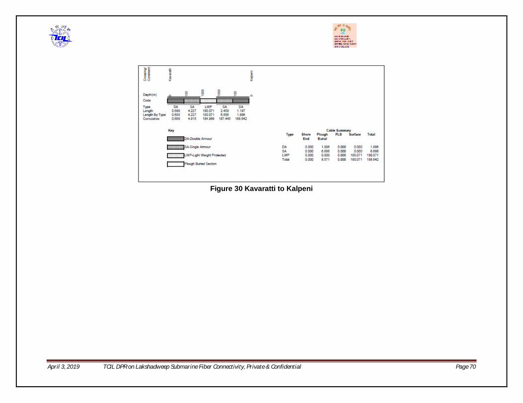
April 3, 2019 TCIL DPR on Lakshadweep Submarine Fiber Connectivity, Private & Confidential Page 70
Figure 30 Kavaratti to Kalpeni
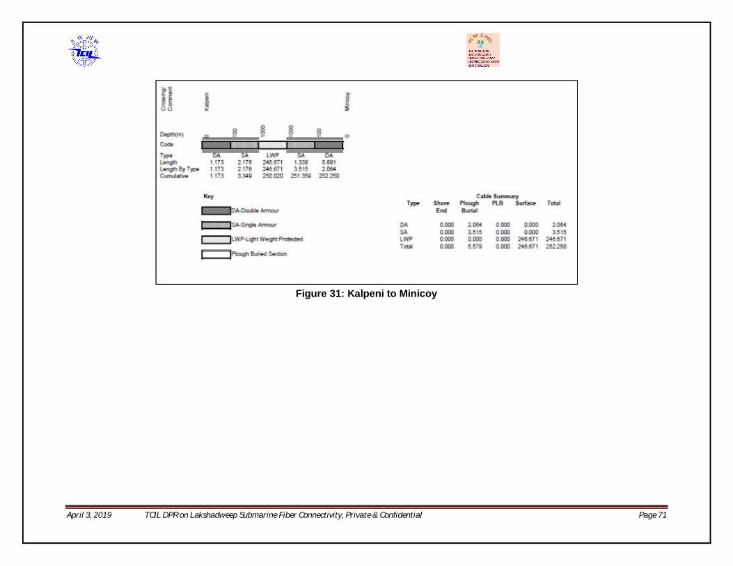
April 3, 2019 TCIL DPR on Lakshadweep Submarine Fiber Connectivity, Private & Confidential Page 71
Figure 31: Kalpeni to Minicoy
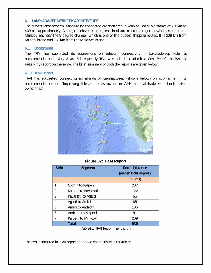
6. LAKSHADWEEP NETWORK ARCHITECTURE The eleven Lakshadweep islands to be connected are scattered in Arabian Sea at a distance of 200km to 400 km. approximately. Among the eleven islands, ten islands are clustered together whereas one island Minicoy lies near the 9 degree channel, which is one of the busiest shipping routes. It is 209 km from Kalpeni island and 130 km from the Maldives Island.
6.1. Background The TRAI has submitted its suggestions on telecom connectivity in Lakshadweep vide its recommendation in July 2104. Subsequently TCIL was asked to submit a Cost Benefit analysis & Feasibility report on the same. The brief summary of both the reports are given below.
6.1.1. TRAI Report TRAI has suggested connecting six islands of Lakshadweep (shown below) on submarine in its recommendations on “Improving telecom infrastructure in A&N and Lakshadweep islands dated 22.07.2014”.
Figure 32: TRAI Report
S.No Segment Route Distance (as per TRAI Report)
(in Kms)
1 Cochin to Kalpeni 287
2 Kalpeni to Kavaratti 122
3 Kavaratti to Agatti 66
4 Agatti to Amini 66
5 Amini to Androth 105
6 Androth to Kalpeni 81
7 Kalpeni to Minicoy 209 Total 936
Table15: TRAI Recommendation
The cost estimated in TRAI report for above connectivity is Rs. 468 cr.
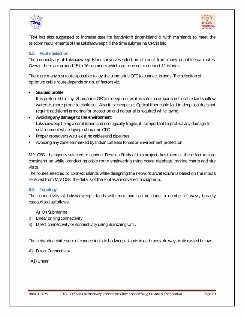
April 3, 2019 TCIL DPR on Lakshadweep Submarine Fiber Connectivity, Private & Confidential Page 73
TRAI has also suggested to increase satellite bandwidth (inter-island & with mainland) to meet the telecom requirements of the Lakshadweep till the time submarine OFC is laid.
6.2. Route Selection The connectivity of Lakshadweep Islands involves selection of route from many possible sea routes. Overall there are around 15 to 16 segments which can be used to connect 11 islands.
There are many sea routes possible to lay the submarine OFC to connect islands. The selection of optimum cable route depends on no. of factors viz.
Sea bed profile It is preferred to lay Submarine OFC in deep sea as it is safe in comparison to cable laid shallow waters is more prone to cable cut. Also it is cheaper as Optical fiber cable laid in deep sea does not require additional armoring for protection and no burial is required while laying.
Avoiding any damage to the environment Lakshadweep being a coral island and ecologically fragile, it is important to protect any damage to environment while laying submarine OFC.
Proper crossovers w.r.t existing cables and pipelines
Avoiding any zone earmarked by Indian Defense forces or Environment protection M/s OSS , the agency selected to conduct Desktop Study of this project has taken all these factors into consideration while conducting cable route engineering using ocean database ,marine charts and site visits. The routes selected to connect islands while designing the network architecture is based on the inputs received from M/s OSS. The details of the routes are covered in chapter 5.
6.3. Topology The connectivity of Lakshadweep islands with mainland can be done in number of ways, broadly categorized as follows:
A) On Submarine i) Linear or ring connectivity ii) Direct connectivity or connectivity using Branching Unit.
The network architecture of connecting Lakshadweep islands in each possible ways is discussed below:
A) Direct Connectivity
A1) Linear

April 3, 2019 TCIL DPR on Lakshadweep Submarine Fiber Connectivity, Private & Confidential Page 74
Figure 33: Linear Connectivity
The above option is showing the linear connectivity to all islands on submarine OFC. The total cable length as per DTS for this option shall be approximately 1344km.
A2) Ring
Figure 34: Ring Connectivity (Option 1)
Ring 1
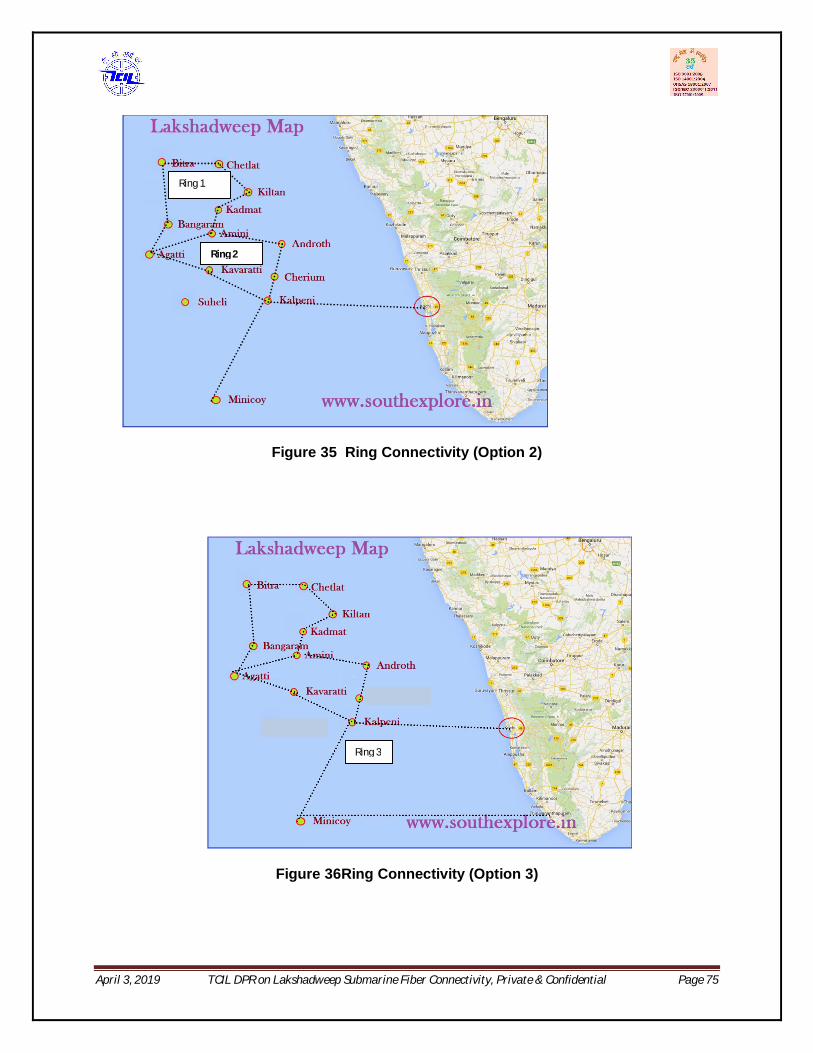
April 3, 2019 TCIL DPR on Lakshadweep Submarine Fiber Connectivity, Private & Confidential Page 75
Figure 35 Ring Connectivity (Option 2)
Figure 36Ring Connectivity (Option 3)
Ring 1
Ring 2
Ring 3

April 3, 2019 TCIL DPR on Lakshadweep Submarine Fiber Connectivity, Private & Confidential Page 76
Figure 37: Ring Connectivity (Option 4)
Figure 38: Option 5
Discussion
The above option are showing possible ring configurations both interisland and with mainland. The first option has one inter island ring covering 10 islands and 11th island (Minicoy) on spur. On addition of another segment from Amini to Agatti in this option, there are two inter –island ring i.e. option 2. The difference in cable length of two options is 110km. and a cost implication of Rs. 52 cr. in submarine cost.

April 3, 2019 TCIL DPR on Lakshadweep Submarine Fiber Connectivity, Private & Confidential Page 77
The inter-island option will give limited redundancy in case of fiber cut with mainland.
Also as per the requirement from Navy it was desired to provide Minicoy island a direct connectivity with mainland (Thiruvananthapuram) as it has strategic importance. This link shall have a cable length of approximately 500 km. and hence shall be repeatered segment.
Addition of this link will provide ring redundancy to entire Lakshadweep island group with mainland. The ring will complete from Kochi to Trivandrum using existing BSNL network.
Option 3, Option 4 and Option 5 shows the possible connections of providing ring redundancy to Minicoy .
Option 3: The two links added with Minicoy islands are: Minicoy to Kalpeni and Minicoy to Thiruvananthapuram . The DTS of Minicoy to Kalpeni has already been done and route length is 242 kms with cable length of 252 kms as per report. The pros of this option is that it will provide ring redundancy with mainland and con is that it will have a single point failure at Kalpeni, which may result in total disability of Lakshadweep islands. To solve this issue below options are suggested.
Option 4: Connect Kavaratti to Minicoy and Androth to Kozikhode. Distance of this link may be in excess of 100 kms and is subject to DTS and route study. The advantage is that it will remove repeatered segment from the network architecture (Minicoy to Kavaratti can work as unrepeatered using in line amplifiers). In a meeting conducted on 8th May 2018 in TCIL for the presentation on DTS report attended by Navy Representative, USOF, DoT & TCIL, this option was also discussed. However, before selecting this option the opinion of Navy, their requirement and a confirmation from them may be sought.
Option 5: Connect Minicoy to Kavaratti: This will alter the scenario to the extent that even if Kalpeni fails, Minicoy is still linked to capital of UT and another location on mainland. The distance of this link is about 252 kms and cable length may increase to about 270 km or thereabouts. This is subject to DTS and route study. The advantage is that it will provide Kavaratti Island, capital of U.T. of Lakshadweep two way connectivity with mainland.
The below table summarizes the above options, however in the absence of DTS of some of the links the submarine cost for all the options could not be calculated.
It may be noted that submarine cost is the cost incurred only towards submarine system components. The others cost like civil construction of CLS , PMC etc. are separate and detailed in next chapter.
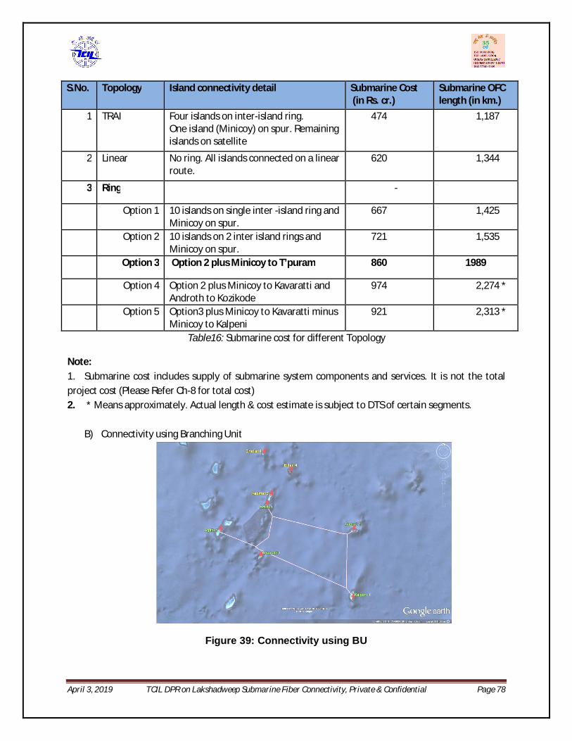
April 3, 2019 TCIL DPR on Lakshadweep Submarine Fiber Connectivity, Private & Confidential Page 78
S.No. Topology Island connectivity detail Submarine Cost (in Rs. cr.)
Submarine OFC length (in km.)
1 TRAI Four islands on inter-island ring. One island (Minicoy) on spur. Remaining islands on satellite
474 1,187
2 Linear No ring. All islands connected on a linear route.
620 1,344
3 Ring -
Option 1 10 islands on single inter -island ring and Minicoy on spur.
667 1,425
Option 2 10 islands on 2 inter island rings and Minicoy on spur.
721 1,535
Option 3 Option 2 plus Minicoy to T’puram 860 1989
Option 4 Option 2 plus Minicoy to Kavaratti and Androth to Kozikode
974 2,274 *
Option 5 Option3 plus Minicoy to Kavaratti minus Minicoy to Kalpeni
921 2,313 *
Table16: Submarine cost for different Topology
Note: 1. Submarine cost includes supply of submarine system components and services. It is not the total project cost (Please Refer Ch-8 for total cost) 2. * Means approximately. Actual length & cost estimate is subject to DTS of certain segments.
B) Connectivity using Branching Unit
Figure 39: Connectivity using BU

April 3, 2019 TCIL DPR on Lakshadweep Submarine Fiber Connectivity, Private & Confidential Page 79
It is possible to connect Lakshawdeep islands using Branching Unit (BU). This will save the cost of submarine OFC cable and provide cable protection i.e. in case of cable cut in shallow water (connected through BU), it will be possible to operate the trunk route when a fiber is cut in shallow water near the site.
There may also be saving in the cost involved in laying cable near shore as by using BU the submarine OF cable laying shall be one time only. However at the same time it will add the cost of a new network element i.e. BU. Also by using BU in connectivity, the physical ring redundancy shall not be achievable.
The cost benefit analysis shows that there will be no reduction in shore end cost as both cable (entering & exiting the shore) shall be laid in the same corridor. Now a days the practice is to pull the Submarine OFC towards shore in single operation.
Also laying of BU will cost additional mainlay Installation Vessel standby days (2-3 days per BU deployment) which will increase the marine installation costs. Also a second vessel would be required to buoying off the BU cable tail, wet storage of cable and later its installation. In additional there will be impact on overall maintenance costs of BU configuration system.
6.4. System Design A submarine OFC communication network consists of a number of components viz. submarine optical fiber cable (OFC), land cable, Submarine equipment, Joint Box, Amplifiers/ repeaters, Power Feeding Equipment required in case of long distance submarine cable length exceeding 300 km. to 400km.,equalizers, Branching unit etc. .
The system design primarily depends on network architecture and bandwidth requirement which decides the OFC cable size and number of fiber in it and equipment configuration. The other components are generally standard and vary with the length of the cable or location of the site, they shall be covered in the Bill of Quantity (BoQ).
The submarine OFC cable and equipment configuration are discussed in detail below.
6.4.1. Number of fiber in Lakshadweep Submarine Optical Fiber Cable Generally, world-wide submarine cables are laid to connect different continents, thus it cover thousands of kilometer and therefore repeatered submarine OFC. It is seen that globally number of fiber pair (fp) laid vary from 2fp to 8fp depending upon the requirements in submarine cable commercially.
The different factors to be considered while selection of number of fiber pair in a submarine OFC are:
a) Requirement b) Topology c) Cost

April 3, 2019 TCIL DPR on Lakshadweep Submarine Fiber Connectivity, Private & Confidential Page 80
The number of fiber in any Submarine Optical Fiber Cable depends on requirement. The number of fiber in a submarine OFC will always be in even number(pair) i.e. 2 fiber pair (fp), 3fp, 4fp, 5fp, 6fp and so on. It varies from minimum 1 fiber pair and can go upto 16 fiber pair depending on need.
The number of fiber pair also depends on the topology selected for connecting islands i.e. directly or through Branching unit. If the network is designed using branching unit where a dedicated fiber pair is dropped in each island, more number of fiber pair may be required. In case of collapsed ring network architecture, same number of fibers can be routed to each island.
The cost of the submarine OFC is another important factor as it may affect the budget of the project. The cost of a submarine OFC varies with the increase in number of fiber pair. It increases significantly in case of repeatered cable because it involves assembly of repeaters which are active component required to regenerate optical signal.
In case of unrepeatered cable, the increase in cost with the increase in fiber pair is not substantial and generally the trend in cost increase with adding each fiber pair in a unrepeatered cable is linear. Any standard submarine OFC can accommodate only upto a certain limit of fiber pair, this number depends on submarine OFC manufacturers. The cost of the submarine OFC cable may increase after a limit is reached owing to increase in size of cable.
The incremental cost towards increase in fiber pair also depends on its technical specifications and also varies with submarine vendors.
Approximate Estimate of Cost variation per fiber pair
No. of Fiber pair (fp) Incremental Cost of increasing Fiber Pair in Lakshadweep (in Rs. cr.)
4 fp to 5fp 9.19 4 fp to 6 fp 18.38
Fiber Pair in Lakshadweep Submarine OFC
The traffic carrying capacity of a fiber depends on the terminal equipment and the distance it has to traverse before landing on a site. As most of the segments in Lakshadweep are un-repeatered, except Minicoy to Trivandrum which may require installation of Inline amplifiers, the distance will not pose any limit to the traffic carrying capacity. The present technology used in submarine line terminating equipment (SLTE) enable to transmit optical traffic carrying signal in multiples of wavelength (capacity 100 Gbps) on a single fiber. The number of 100 Gbps signals which can be sent through a SLTE on a single fiber pair varies with equipment manufacturer, it can go upto as high as 144 wavelengths i.e. 14.4 Tbps. Therefore, a single fiber has very large traffic carrying capacity.

April 3, 2019 TCIL DPR on Lakshadweep Submarine Fiber Connectivity, Private & Confidential Page 81
As per the bandwidth requirement assessed in Chapter 3 of the report, it is clear that to meet the traffic requirements of Lakshadweep islands, a single fiber pair is sufficient. In addition Navy has desired one fiber pair in all islands. Therefore the minimum requirement of Lakshadweep is at least two fiber pair.
The recommended network architecture for Lakshadweep as discussed in previous section has direct connectivity to all islands and no use of Branching Unit. Therefore all fiber pair shall be routed to all islands.
The cost of adding each fiber pair in Lakshadweep is estimated at approximately Rs. 9 Cr. However as the additional number of fiber pair can be added for providing fiber redundancy, and also to make the network futuristic. These additional fibers can be used to extend the connectivity of India with other continents like Africa and Maldives .
Considering all points above, it is proposed to lay six fiber pair (6fp) in Lakshadweep network. A six fiber pair submarine cable can be suitably used as below:
a. One pair for telecom connectivity to Lakshadweep islands. b. One pair for dedicated use by defense forces. c. The four extra fiber pair shall be kept in unlit condition as reserve to cater any requirement
towards fiber redundancy or network extension.
SLTE
ODF
CTB
SIE
1 fiber pair for commercial traffic
1 fiber pair for Navy/ Defense forces
4 fiber pair reserved for future
Submarine OFC with 6 fiber pair
CTB- Cable Termination BoxSLTE- Submarine Line Terminating EquipmentODF- Optical Distribution FrameSIE- SDH Interconnect Equipment
6.4.2. Submarine Equipment Configuration in Lakshadweep The submarine terminal equipment in an unrepeatered submarine communication network consists of Cable Termination Rack (CTR), Submarine line terminating Equipment (SLTE), SDH Interconnect Equipment (SIE) (optional)/ Optical transport Network Equipment (OTN) and associated Network Management System(NMS) & Data communication network (DCN).All these components are already detailed in chapter 4.

April 3, 2019 TCIL DPR on Lakshadweep Submarine Fiber Connectivity, Private & Confidential Page 82
While the other products are standard items, the configuration of SLTE and SIE as per the Lakshadweep requirements are discussed below:
Submarine Line Terminating Equipment (SLTE)
The present technology used in submarine line terminating equipment (SLTE) enable to transmit optical traffic carrying signal in multiples of 100 Gbps (one wavelength) on a single fiber. The number of 100 Gbps signals which can be sent through a SLTE on a single fiber pair varies with equipment manufacturer, it can go upto as high as 144 wavelengths i.e. 14.4 Tbps.
The SLTE design is modular i.e. its functions are divided into number of cards housed in shelves inside a standard size rack. These cards are categorized as common cards like control card, power units, supervisory card, protection card, Line amplifiers, pump units, Channel or Band multiplexer cards, and transponder card capable of transmitting one wavelength to transmit more wavelengths on single fiber more transponders cards shall have to be added.
In case of Lakshadweep, after analyzing the current and future bandwidth requirement we can configure per site with one SLTE with design capacity of 16 wavelengths initially equipped with one wavelength (100Gbps). The SLTE facing submarine OFC is known as the line side, while the other side (facing client) is known as client side which would be connected to the Cross connect equipment through a 10G interface.
Equipment configuration on all islands: -1 SLTE (Submarine Line Terminating Equipment) per site per segment
- Design Capacity 16 X 100 Gbps - Equipped Capacity 02 X 100 Gbps
01X100Gbps working 01X100Gbps spare
Redundancy in Equipment
To protect the traffic from any kind of equipment failure, there is a need to protect the equipment by ensuring redundancy.
Generally there is no equipment redundancy sought in the existing submarine communication system carrying commercial traffic except redundancy of power cards. This is also because any Telecom service provider ensures bandwidth connectivity on submarine OFC by investing or buying bandwidth from at least two different submarine cable, thereby ensuring traffic protection in case of cable cut.
In case of Lakshadweep as this shall be the first submarine cable system, it will not be possible to provide redundancy on any other submarine cable system. Also it will take time to rectify any card because of transportation problem with islands.
The redundancy can be achieved by either replicating the entire equipment or some of its critical cards.

April 3, 2019 TCIL DPR on Lakshadweep Submarine Fiber Connectivity, Private & Confidential Page 83
As the design of SLTE is modular, it is recommended to replicate all critical cards like amplifier, mux demux card, power card, transponder card.
SDH Interconnect Equipment (SIE) (optional)/ Optical transport Network Equipment (OTN)
The SIE would provide the add/drop and cross-connect functions for terminating traffic in a landing station. The 10G client signals from SLTE would be terminated on the SDH equipment and can be cross connected to several lower order ports as per customer needs at any landing site. A standard SDH box usually has internally duplicated matrix and control cards and also power supply and fan units.
The network protection would be provided by means of SDH function. For SDH dimensioning ports for every station would vary depending upon the traffic need originating/terminating at every landing and hence would involve interfaces from STM16 to E-1 level.
The SDH interconnect Equipment facing line interfaces towards customer side shall have cross connect function and multiple ports as follows:
1. 10 GigE Ethernet 2. 10 Gbps OTU2 3. STM-64 4. STM-16
The no. of ports shall vary and depend on manufacturer.
The below diagram is showing the routing of one lit fiber as suggested in network design and as per topology option2.
SLTE
SLTE
SLTE
SLTE
SLTE
SLTE
SLTE
SLTE
SLTE
SLTE
SLTE
SLTE
SLTE
SLTE
SLTE
SLTE
SLTE
SLTE
SLTE
S L T E
S L T E
S L T E
S L T E
S L T E
KALPENIANDROTH
MINICOY
KOCHI
KAVARATTI
AGATTI
BANGARAM
BITRA CHETLAT KILTANKADMAT
AMINI
Figure 40: Fiber Routing Diagram
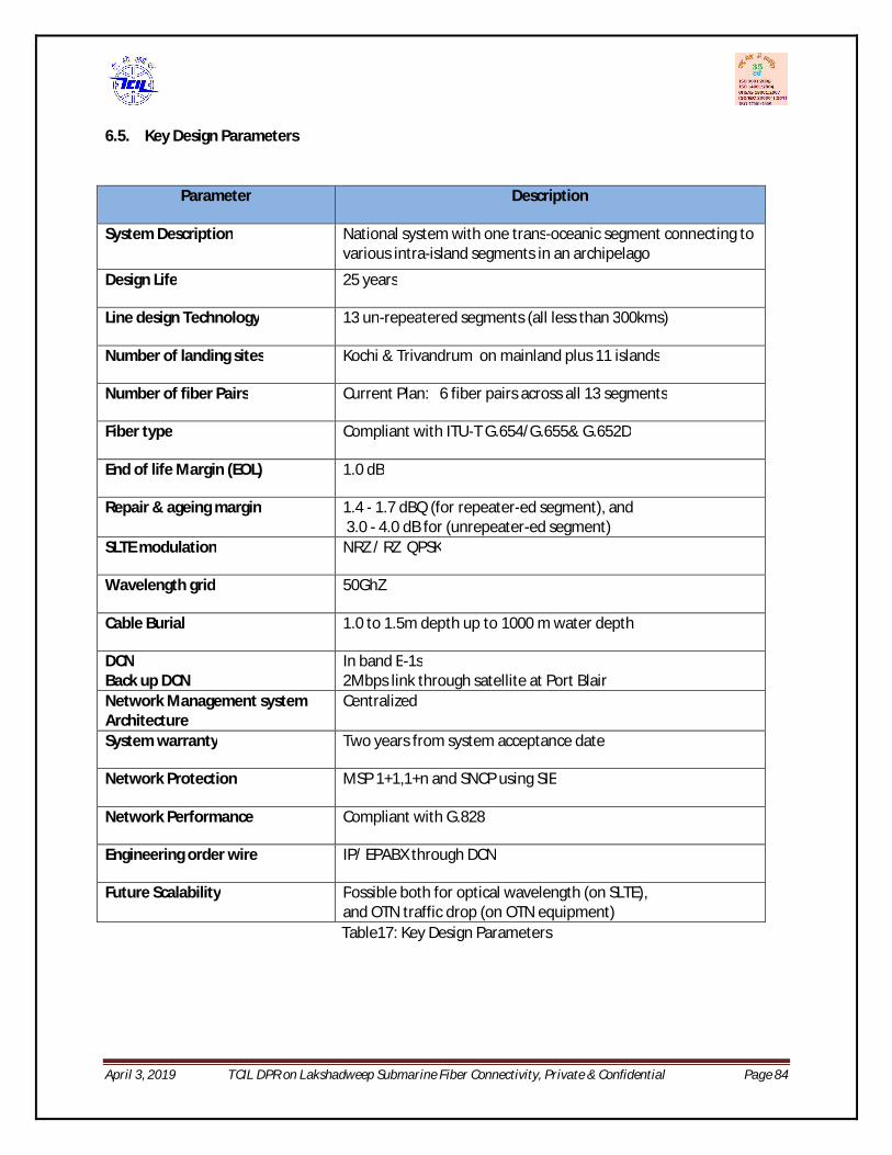
April 3, 2019 TCIL DPR on Lakshadweep Submarine Fiber Connectivity, Private & Confidential Page 84
6.5. Key Design Parameters
Parameter Description
System Description National system with one trans-oceanic segment connecting to various intra-island segments in an archipelago
Design Life 25 years
Line design Technology 13 un-repeatered segments (all less than 300kms)
Number of landing sites Kochi & Trivandrum on mainland plus 11 islands
Number of fiber Pairs Current Plan: 6 fiber pairs across all 13 segments
Fiber type Compliant with ITU-T G.654/G.655& G.652D
End of life Margin (EOL) 1.0 dB
Repair & ageing margin 1.4 - 1.7 dBQ (for repeater-ed segment), and 3.0 - 4.0 dB for (unrepeater-ed segment)
SLTE modulation NRZ / RZ QPSK
Wavelength grid 50GhZ
Cable Burial 1.0 to 1.5m depth up to 1000 m water depth
DCN Back up DCN
In band E-1s 2Mbps link through satellite at Port Blair
Network Management system Architecture
Centralized
System warranty Two years from system acceptance date
Network Protection MSP 1+1,1+n and SNCP using SIE
Network Performance Compliant with G.828
Engineering order wire IP/ EPABX through DCN
Future Scalability Possible both for optical wavelength (on SLTE), and OTN traffic drop (on OTN equipment) Table17: Key Design Parameters
April 3, 2019 TCIL DPR on Lakshadweep Submarine Fiber Connectivity, Private & Confidential Page 85
6.6. Redundancy Currently the redundancy in case of any submarine fiber cut is planned on satellite. However, the submarine cable cut is though rare but it takes several days to repair the cut depending on the location and availability of the ship. Satellite can only provide limited bandwidth therefore redundancy on fiber is important. Issue - Lack of Network resiliency The network configuration in its currently envisaged state has one serious drawback – lack of network resiliency. It provides a single point-of-connectivity to Indian mainland, at Kochi from the islands main city of Port Blair. All other segments are sequential intra-island segments. Although good care would be taken to select the best route that reduces all external risks of cable damage to minimum, still cable damage could not be completely ruled out (in our opex estimates we assume that one submarine repair would be needed per year). In the event of unfortunate cable damage, occurring anywhere on this longest segment connecting to mainland, the entire island connectivity would be lost for several days. As cable repair would require mobilisation of a repair vessel (most probably from a location in South East / South Asia-Singapore / Colombo), including transit, port clearance, repair, testing etc, the entire operation can take 12-16 days in the most optimistic conditions. Such a long period can have severe strategic, defense and economic consequences, especially after getting accustomed to availability of high bandwidth e.g if this outage were to happen during peak tourist season, it would have a severe economic impact on the local economy with a echoes of poor connectivity and bandwidth availability would impact future tourism. In all, a cable fault of reasonable extent might potentially leave the islands without any connectivity for 3 - 4 weeks, if one factors in some delays in permitting, import and re-export of vessel etc. Besides there would always exist a high risk of running into further delays if weather conditions are not favorable to enable the repair vessel to carry out the timely repairs, which in the case of the Lakshawdeep is a considerable factor given the long and severe monsoon period. This situation might prove to be very disastrous not only for islands inhabitants, tourist but also for Island administration. Even if some alternate satellite bandwidth is available for backing-up in this emergent scenario, it would be extremely scarce and could just provide few voice communication points. International practices for maintaining traffic continuity during cable faults Typically, all major submarine networks today bring in the resiliency in their network for maintaining the traffic continuity during cable damage, by way of, either: i. Re-routing traffic through an alternate path inbuilt within the network architecture, or ii. Restoring traffic on another cable originating / terminating between same landing points.

April 3, 2019 TCIL DPR on Lakshadweep Submarine Fiber Connectivity, Private & Confidential Page 86
This planning is made and executed during the construction phase of a new cable system itself by designing an appropriate resilient configuration, so that the system when gets commissioned is adequately safe-guarded against such risks from beginning itself. A cable system not incorporating such features generally has a low market value, as compared to its peer where the traffic is expected to be more secured. Recommendation for making the system resilient against cable faults As traffic restoration possibility is ruled out for this proposed Lakshadweep cable due to absence of any other cable in the island hence it becomes important to have a second connectivity to mainland from the Minicoy to form a ring. The length of point-to-point cable link between Minicoy to Trivandrum is around 426 km [From Google Maps]. Minicoy is important from strategic and national security point of view. It was discussed in meeting at Kochi on 09.03.18 for the project with opinions from Navy representative and Lakshawdeep administration to provide connectivity between Minicoy to Trivandrum. The terrestrial cable existing between Trivandrum and Kochi will complete the ring. Therefore, in the event of submarine fiber cut, the most essential bandwidth requirement of Lakshadweep islands may be met through satellite till the time alternate media is made available.

April 3, 2019 TCIL DPR on Lakshadweep Submarine Fiber Connectivity, Private & Confidential Page 87
7. Project Cost A main aspect for any project is accurate assessment of the cost involved in executing the project.
The estimated cost of this project is categorized in two categories
7.1. CAPEX (CAPITAL EXPENDITURE) This is one time capital expenditure cost of implementing the project. This shall include following costs:
Submarine system cost This shall include all cost towards laying the submarine OFC i.e.
i. Cost towards permits required prior to and while execution of project. ii. Cost towards Submarine components like Submarine OFC, Terminal Equipment, NMS
(hardware & software),traffic surveillance or monitoring equipment costs, Land Cable, Joint Box, Routers, workstation (NOC), spares, Test equipment, Documentation.
iii. Cost towards services like Marine activities (cost of marine survey and laying of submarine cable on sea –bed, construction of Beach Manhole, Laying of land cable, submarine Plant loading (on ship), system commissioning, Acceptance testing, Insurance, warranty, training.
iv. Cost towards Project Management (incurred by submarine vendor)
Civil Costs This includes cost towards construction/upgradation of Cable landing stations.
i. Civil infrastructure for readiness of Cable landing station (if existing) else building construction, construction of Beach manhole, laying of ducts for land cable.
ii. Cable station Infrastructure costs (AC plant, power plant, access control etc.) iii. Utilities like fire detection & alarm, rodent repellants, CCTV access, water leakage detection
etc.( cost included in cable station infrastructure)
Project Management cost The cost incurred by Project execution agency and project monitoring agency.
Taxes The applicable taxes like GST (IGST), Custom Duty, insurance, Local transport taxes etc.
Contingency Cost reserved to cover expenses towards any unforeseen activity which could arise in the project.
Cost towards Permissions & licenses
As seen in the case of A&N island submarine project, there are permissions required prior to execution of the project and after the project award i.e. while execution of the project.
The permissions required prior to execution are Permit in principle (PIP) given by DoT. So no cost is kept towards this, as it is a DoT project. Another permission is for getting the Coastal Regulation Zone (CRZ)

April 3, 2019 TCIL DPR on Lakshadweep Submarine Fiber Connectivity, Private & Confidential Page 88
clearance of the project from Coastal Zone Management Authority (CZMA) and Ministry of environment. A cost provision of Rs. 5 Cr. is kept towards this permission.
The remaining permissions are to be obtained at the time of execution and it is assumed that cost towards same shall be borne by the selected submarine vendor. However in BSNL recently issued tender for ANI in which separate charges are mentioned towards vessel entry (options for 6 months or 9 months) as a percentage of custom duty & bond. As it depends on the type and cost of vessel, it is difficult to estimate it. Hence a provision of 1% shall be taken in the head of contingency to cover this cost.
Submarine Cost
The submarine cost of connecting Lakshadweep islands is done using the rates received in the bid of tender recently floated by BSNL for connecting A&N islands on submarine OFC has been used. The rates included charges towards Custom Duty, GST (@18% on most of the items), Insurance upto PAC, Transportation Cost only for locally procured items.
The submarine cost assessment is made under various head i.e. 1) Submarine OFC & Accessories, 2) Marine Activities 3) Land Cable 4) Submarine Terminal Equipment 5) Installation cost 6) Project Management and System commissioning and Acceptance Testing.
Bill of Quantity
The Bill of Quantity (BoQ) of submarine OFC i.e. cable route length is taken from DTS findings. The other components are taken as per the system design and network architecture.
Submarine Cost
The below section cover the cost of recommended topology i.e. Connecting 11 islands on submarine OFC at Kochi and Trivandrum respectively.

April 3, 2019 TCIL DPR on Lakshadweep Submarine Fiber Connectivity, Private & Confidential Page 89
S.No. Submarine Head Cost (In Rs. Cr.) 1 Submarine OFC & Components 161 2 Marine Activities 361 3 Land Cable 46 4 Submarine Terminal Eqpt 142 5 Installation of Eqpt. 30 6 Project Management , System commissioning & AT 119 Total 860
Table19: Submarine Cost
Submarine Cost Analysis The following approximate break upon various heads in a submarine cost s given below:
S.No. Submarine Head Percentage of total Cost
1 Submarine OFC & Components 19% 2 Marine Activities 42% 3 Land Cable 5% 4 Submarine Terminal Eqpt. 17% 5 Installation of Eqpt. 3% 6 Project Management , System commissioning & Testing 14%
Table18: Break up of submarine Cost under various head (in %age)
This percentage cost break up may vary for different segment specifically the submarine OFC Component and Laying cost depending on the length of the segment and route at which it will be laid on sea.

April 3, 2019 TCIL DPR on Lakshadweep Submarine Fiber Connectivity, Private & Confidential Page 90
Other CAPEX Heads
The other cost elements that are important to be considered for the CAPEX budgeting of a submarine cable project are;
a) Civil infrastructure costs (BMH, land ducts and Cable station up-liftment) The civil work in the submarine project shall include construction of Beach manhole (BMH), Cable landing station, laying land cable from BMH to CLS and some degree of civil up-liftment would be needed to make them ready for receiving equipment and cable (like duct and chut construction, earthing, painting, leakage proofing, flooring etc). The BMH and land routes are considered as entire greenfield constructions. As per the site visit of the islands, it was seen that except Bangaram island where new building needs to be constructed, all the islands have sufficient space for CLS in existing BSNL facilities. However most of them are on ground floor and for CLS first floor needs to be constructed. As the rate of civil construction will vary significantly in Lakshadweep owing to the cost of transportation of raw material and labour Charges. An estimation on the basis of cost of building construction and upgradation provided by BSNL in A&N islands was made. The same was around 3% of estimated submarine cost. A Provision of 5% of submarine cost is taken towards civil works required towards Cable landing station.
b) Cable station infrastructure costs (AC Cooling, power plant, access control etc) The Power requirement in a submarine cable landing station depends on the type of power consumption by the i.e. on AC power or DC power and AC cooling to maintain ambient temperature and to counter heat dissipation in a Cable landing station. Typically, the AC power consumption ranges from 3 KW to 4 KW and DC power ranges from 6 KW to 7 KW on a unrepeatered segment site. In case of repeatered segment the power consumption to the PFE (power feeding equipment) which ranges from 1500 V to 2500 V depending on the distance covered by the segment is also added in total consumption. The amount of power consumption varies with different submarine equipment manufacturers. Also, the estimation of power consumption on a single site depends on the network architecture i.e. number of segments terminated on a site, length of segment (to assess requirement of Inline amplifiers) and number of active equipment. In case of Lakshadweep, there are 5 station that shall require power of the order of 12 KW to 14KW. Another 5 stations shall require less than 10 KW. The sites with multiple landing shall like Kalpeni and repeatered segment (Minicoy to Trivandrum) shall require 15 KW to 20 KW. The cost towards this is included in previous head “Civil Infrastructure costs”.
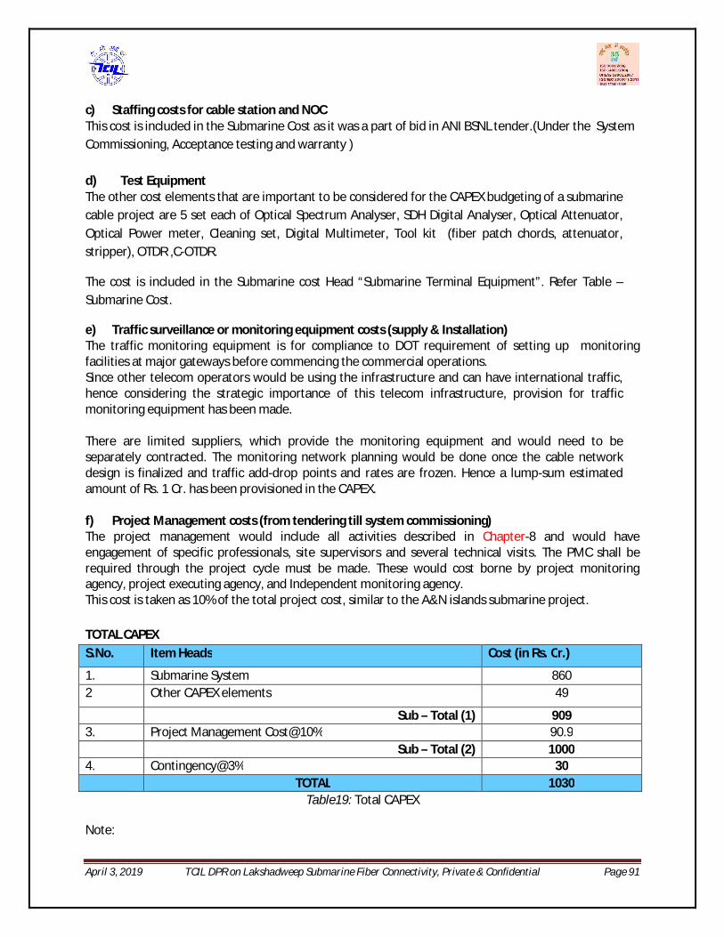
April 3, 2019 TCIL DPR on Lakshadweep Submarine Fiber Connectivity, Private & Confidential Page 91
c) Staffing costs for cable station and NOC This cost is included in the Submarine Cost as it was a part of bid in ANI BSNL tender.(Under the System Commissioning, Acceptance testing and warranty ) d) Test Equipment The other cost elements that are important to be considered for the CAPEX budgeting of a submarine cable project are 5 set each of Optical Spectrum Analyser, SDH Digital Analyser, Optical Attenuator, Optical Power meter, Cleaning set, Digital Multimeter, Tool kit (fiber patch chords, attenuator, stripper), OTDR ,C-OTDR.
The cost is included in the Submarine cost Head “Submarine Terminal Equipment”. Refer Table – Submarine Cost.
e) Traffic surveillance or monitoring equipment costs (supply & Installation) The traffic monitoring equipment is for compliance to DOT requirement of setting up monitoring facilities at major gateways before commencing the commercial operations. Since other telecom operators would be using the infrastructure and can have international traffic, hence considering the strategic importance of this telecom infrastructure, provision for traffic monitoring equipment has been made.
There are limited suppliers, which provide the monitoring equipment and would need to be separately contracted. The monitoring network planning would be done once the cable network design is finalized and traffic add-drop points and rates are frozen. Hence a lump-sum estimated amount of Rs. 1 Cr. has been provisioned in the CAPEX. f) Project Management costs (from tendering till system commissioning) The project management would include all activities described in Chapter-8 and would have engagement of specific professionals, site supervisors and several technical visits. The PMC shall be required through the project cycle must be made. These would cost borne by project monitoring agency, project executing agency, and Independent monitoring agency. This cost is taken as 10% of the total project cost, similar to the A&N islands submarine project. TOTAL CAPEX S.No. Item Heads Cost (in Rs. Cr.)
1. Submarine System 860 2 Other CAPEX elements 49
Sub – Total (1) 909 3. Project Management Cost@10% 90.9
Sub – Total (2) 1000 4. Contingency@3% 30
TOTAL 1030 Table19: Total CAPEX
Note:

April 3, 2019 TCIL DPR on Lakshadweep Submarine Fiber Connectivity, Private & Confidential Page 92
1. Other CAPEX elements includes cost towards:
CLS construction & upgradataion - estimated @5% of submarine cost
CRZ clearance and traffic surveillance equipment – provision of Rs. 6 cr. based on estimation of ANI project.
2. PMC: The cost incurred by Project execution agency and project monitoring agency. 3. Contingency: It includes cost towards vessel entry charges, currency fluctuation, inflation and any unforeseen expenses.
7.2. OPEX The Operational and Maintenance of a submarine telecom cable system shall involve various types of maintenance mainly:
1. Stand-by Maintenance: Always on stand-by, ready to deploy at any moment when a failure occurs. In this project, for the stand-by maintenance a team comprising a managerial level, a engineer and a technician shall be stationed at every Cable landing station. 2. On-call Maintenance: Failure recovery team is assembled each time a failure occurs. In this project, a on call maintenance shall be required in case of failure of equipment at terminal station for which AMC of both submarine and SDH equipment is provisioned. Any Cut in the land cable is assumed to be handled by the existing BSNL maintenance teams as they are readily available. Any cut in the submarine cable shall be handled by signing a contract with a specialized agency who is experts in repairing these cuts. The operational expenditure incurred in providing maintenance is categorized below:
Cable repair charges (in case of submarine cable cut)
AMC towards Submarine System
Operation & Management of Cable Landing Station
Preventive Maintenance
The details of the activities involved in maintenance are given as under:
Cable Repair /Wet Plant Maintenance
Depending on the location, environment, and the nature of the failure, there are many conceivable methods of carrying out repairs to the submarine cable.
The shallow water repair can be done with the help of small vessels locally available , divers and specially trained jointers who charge around $2000 a day.
The deep-water repairs (for water depths greater than 20m) are carried out on board the cable-laying vessel, equipped with facilities to repair and test the cable. The cable is retrieved, the damaged parts removed, re-connected and then laid back again.
April 3, 2019 TCIL DPR on Lakshadweep Submarine Fiber Connectivity, Private & Confidential Page 93
The special feet vehicle used to maintain the exiting submarine fiber cables are few and have divided world into submarine maintenance zone. The submarine cable under this project lies in the zone of SEAICOMA (South East Asia and Indian Ocean Cable Maintenance Agreement). A standard contract provided by SEAICOMA needs to be signed for submarine fiber cable maintenance. The spare provided by the supplier of this project for submarine cable shall be loaded in this ship. This Agreement constitutes various Indian Ocean and South Asian cable systems along with the available ship and depot owners. Because of pooled resources of cable ship operators and depot owners and sharing of costs by various cable systems, this sort of arrangement is the most efficient one to for economically viable maintenance of wet plant of cable systems.
Before the cable system gets operational, it has to initiate discussion and become a signatory to the agreement, after which the services become available at specified rates (as fixed costs) and variable costs (per repair) to be incurred. The contract mainly includes two type of charges fixed charges for base depot charges and variable charges in case of cable cut including mobilization of ship, ship transit charges, ship in port charges , loading unloading of spares, repairing charges etc.
Based on the analysis of number of fiber cut in existing submarine cables which land on Indian shore, assumption of one fiber cut per year is considered for estimating these charges.
Submarine Cable Maintenance by SEAICOMA:
o Fixed Marine Maintenance o Variable Charge for Cable repair AMC for Manpower Charges
The cost under this head is referred from A&N island DPR.
Preventive Maintenance
Inspection is made periodically to check for wear and irregularities of the submarine cables and the necessary repairs are made to pre-empt failures. Periodical inspection of land cable with the help of patrolling team, sensors and CCTV shall be done.
Operation & Management of Cable Landing Station To operate submarine cables under optimum conditions, it is necessary to manage and maintain not only the cables but also the landing stations and other facilities as a system. Normally, the maintenance of the submarine cables and the landing stations (equipment AMC) are undertaken by separate contractors.
To estimate the OPEX in this project, the following Post Commissioning Operation & Maintenance heads are considered.
Dry Plant Maintenance AMC charges to Submarine system supplier for Equipment at CLS. AMC charges for SDH equipment (indigenous portion at CLS)

April 3, 2019 TCIL DPR on Lakshadweep Submarine Fiber Connectivity, Private & Confidential Page 94
AMC for Land Cable Maintenance and Patrolling Team AMC for power plant (DG set, SMPS, UPS , Battery bank) AMC for NOC & software licenses for NMS (included in AMC – Main supplier)
Electricity & Diesel
Building Rental Charges / Co-location Charges
Insurance (cost included in building maintenance)
Manpower charges
Contingency (to cover any price escalation, unforeseen expenditure)
The charges towards these are estimated on lumpsum basis.
It has been estimated for the various head as tabulated below: S. No Items Cost (in Rs.)
1 Wet Maintenance Cost – Fixed Component 78,783,348 2 Wet Maintenance Cost – Variable component 32,181,279 3 Wet Maintenance Cost – Depot charges 3,761,972 4 AMC- Submarine System 43,779,948
5 Utilities (electricity and diesel) 19,950,000 6 Building maintenance 19,950,000 7 Manpower cost 79,800,000
8 Administrative and general expenses 6,650,000
Sub-Total 284,856,546
9 Contingency @10% 28,485,655
Total (in Rs. ) 313,342,200
Total incl. Service Tax @ 18% (Rs ) 369,743,796
Table20: OPEX
The estimated OPEX is approximately 4.39% of project cost. The budgetary estimate towards OPEX is taken as 5% of the CAPEX i.e. Rs 51 Cr including 18% service Tax. A yearly escalation of 10% is taken while estimation of OPEX in subsequent years. TOTAL PROJECT COST
CAPEX 1030
OPEX for 5 years (10% escalation every year) 314 TOTAL COST (In Rs. cr.) 1,344
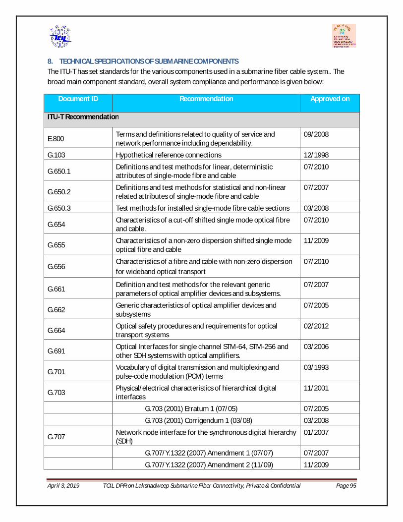
April 3, 2019 TCIL DPR on Lakshadweep Submarine Fiber Connectivity, Private & Confidential Page 95
8. TECHNICAL SPECIFICATIONS OF SUBMARINE COMPONENTS The ITU-T has set standards for the various components used in a submarine fiber cable system.. The broad main component standard, overall system compliance and performance is given below:
Document ID Recommendation Approved on
ITU-T Recommendation
E.800 Terms and definitions related to quality of service and network performance including dependability.
09/2008
G.103 Hypothetical reference connections 12/1998
G.650.1 Definitions and test methods for linear, deterministic attributes of single-mode fibre and cable
07/2010
G.650.2 Definitions and test methods for statistical and non-linear related attributes of single-mode fibre and cable
07/2007
G.650.3 Test methods for installed single-mode fibre cable sections 03/2008
G.654 Characteristics of a cut-off shifted single mode optical fibre and cable.
07/2010
G.655 Characteristics of a non-zero dispersion shifted single mode optical fibre and cable
11/2009
G.656 Characteristics of a fibre and cable with non-zero dispersion for wideband optical transport
07/2010
G.661 Definition and test methods for the relevant generic parameters of optical amplifier devices and subsystems.
07/2007
G.662 Generic characteristics of optical amplifier devices and subsystems
07/2005
G.664 Optical safety procedures and requirements for optical transport systems
02/2012
G.691 Optical Interfaces for single channel STM-64, STM-256 and other SDH systems with optical amplifiers.
03/2006
G.701 Vocabulary of digital transmission and multiplexing and pulse-code modulation (PCM) terms
03/1993
G.703 Physical/electrical characteristics of hierarchical digital interfaces
11/2001
G.703 (2001) Erratum 1 (07/05) 07/2005
G.703 (2001) Corrigendum 1 (03/08) 03/2008
G.707 Network node interface for the synchronous digital hierarchy (SDH)
01/2007
G.707/Y.1322 (2007) Amendment 1 (07/07) 07/2007
G.707/Y.1322 (2007) Amendment 2 (11/09) 11/2009
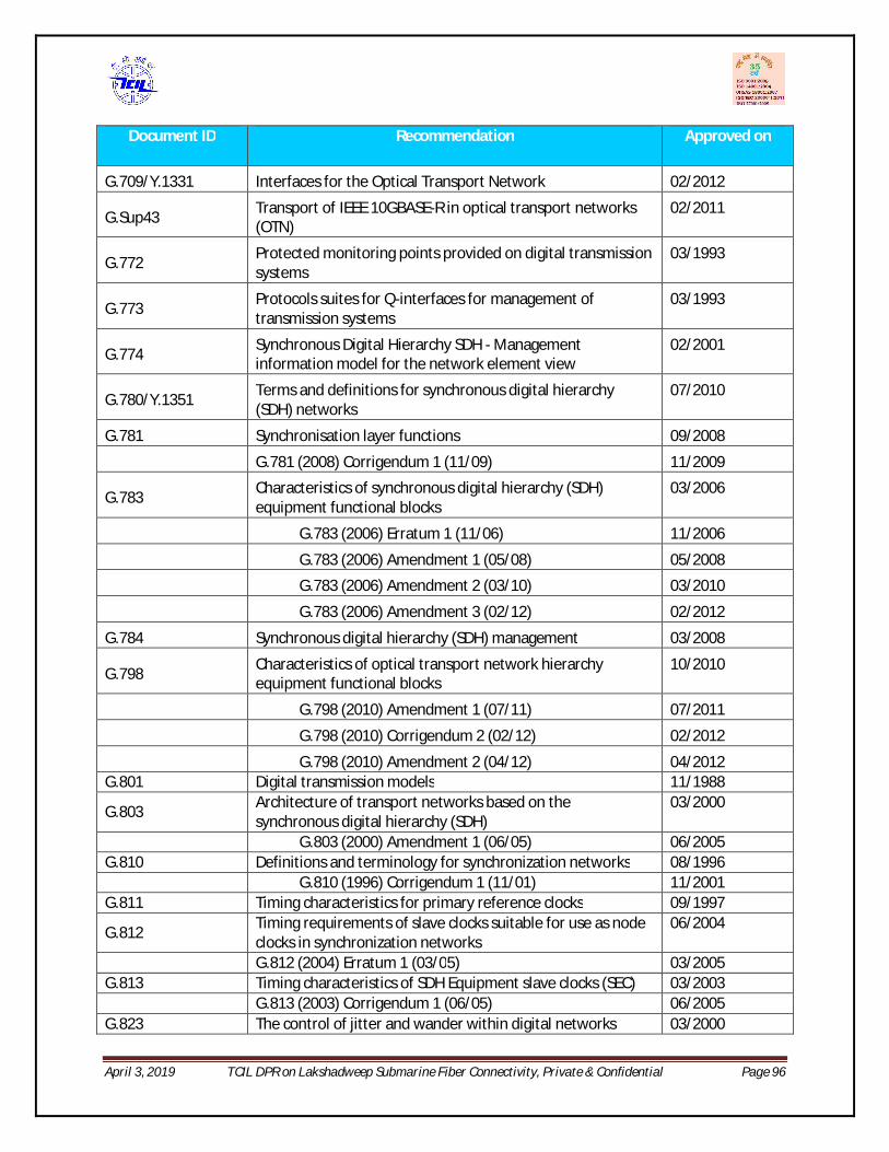
April 3, 2019 TCIL DPR on Lakshadweep Submarine Fiber Connectivity, Private & Confidential Page 96
Document ID Recommendation Approved on
G.709/Y.1331 Interfaces for the Optical Transport Network 02/2012
G.Sup43 Transport of IEEE 10GBASE-R in optical transport networks (OTN)
02/2011
G.772 Protected monitoring points provided on digital transmission systems
03/1993
G.773 Protocols suites for Q-interfaces for management of transmission systems
03/1993
G.774 Synchronous Digital Hierarchy SDH - Management information model for the network element view
02/2001
G.780/Y.1351 Terms and definitions for synchronous digital hierarchy (SDH) networks
07/2010
G.781 Synchronisation layer functions 09/2008
G.781 (2008) Corrigendum 1 (11/09) 11/2009
G.783 Characteristics of synchronous digital hierarchy (SDH) equipment functional blocks
03/2006
G.783 (2006) Erratum 1 (11/06) 11/2006
G.783 (2006) Amendment 1 (05/08) 05/2008
G.783 (2006) Amendment 2 (03/10) 03/2010
G.783 (2006) Amendment 3 (02/12) 02/2012
G.784 Synchronous digital hierarchy (SDH) management 03/2008
G.798 Characteristics of optical transport network hierarchy equipment functional blocks
10/2010
G.798 (2010) Amendment 1 (07/11) 07/2011
G.798 (2010) Corrigendum 2 (02/12) 02/2012
G.798 (2010) Amendment 2 (04/12) 04/2012 G.801 Digital transmission models 11/1988
G.803 Architecture of transport networks based on the synchronous digital hierarchy (SDH)
03/2000
G.803 (2000) Amendment 1 (06/05) 06/2005 G.810 Definitions and terminology for synchronization networks 08/1996 G.810 (1996) Corrigendum 1 (11/01) 11/2001 G.811 Timing characteristics for primary reference clocks 09/1997
G.812 Timing requirements of slave clocks suitable for use as node clocks in synchronization networks
06/2004
G.812 (2004) Erratum 1 (03/05) 03/2005 G.813 Timing characteristics of SDH Equipment slave clocks (SEC) 03/2003 G.813 (2003) Corrigendum 1 (06/05) 06/2005 G.823 The control of jitter and wander within digital networks 03/2000
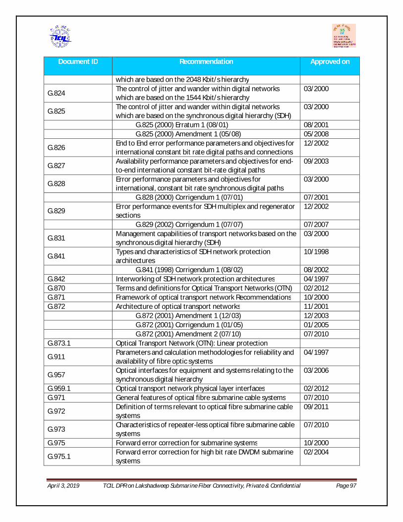
April 3, 2019 TCIL DPR on Lakshadweep Submarine Fiber Connectivity, Private & Confidential Page 97
Document ID Recommendation Approved on
which are based on the 2048 Kbit/s hierarchy
G.824 The control of jitter and wander within digital networks which are based on the 1544 Kbit/s hierarchy
03/2000
G.825 The control of jitter and wander within digital networks which are based on the synchronous digital hierarchy (SDH)
03/2000
G.825 (2000) Erratum 1 (08/01) 08/2001 G.825 (2000) Amendment 1 (05/08) 05/2008
G.826 End to End error performance parameters and objectives for international constant bit rate digital paths and connections
12/2002
G.827 Availability performance parameters and objectives for end-to-end international constant bit-rate digital paths
09/2003
G.828 Error performance parameters and objectives for international, constant bit rate synchronous digital paths
03/2000
G.828 (2000) Corrigendum 1 (07/01) 07/2001
G.829 Error performance events for SDH multiplex and regenerator sections
12/2002
G.829 (2002) Corrigendum 1 (07/07) 07/2007
G.831 Management capabilities of transport networks based on the synchronous digital hierarchy (SDH)
03/2000
G.841 Types and characteristics of SDH network protection architectures
10/1998
G.841 (1998) Corrigendum 1 (08/02) 08/2002 G.842 Interworking of SDH network protection architectures 04/1997 G.870 Terms and definitions for Optical Transport Networks (OTN) 02/2012 G.871 Framework of optical transport network Recommendations 10/2000 G.872 Architecture of optical transport networks 11/2001 G.872 (2001) Amendment 1 (12/03) 12/2003 G.872 (2001) Corrigendum 1 (01/05) 01/2005 G.872 (2001) Amendment 2 (07/10) 07/2010 G.873.1 Optical Transport Network (OTN): Linear protection
G.911 Parameters and calculation methodologies for reliability and availability of fibre optic systems
04/1997
G.957 Optical interfaces for equipment and systems relating to the synchronous digital hierarchy
03/2006
G.959.1 Optical transport network physical layer interfaces 02/2012 G.971 General features of optical fibre submarine cable systems 07/2010
G.972 Definition of terms relevant to optical fibre submarine cable systems
09/2011
G.973 Characteristics of repeater-less optical fibre submarine cable systems
07/2010
G.975 Forward error correction for submarine systems 10/2000
G.975.1 Forward error correction for high bit rate DWDM submarine systems
02/2004

April 3, 2019 TCIL DPR on Lakshadweep Submarine Fiber Connectivity, Private & Confidential Page 98
Document ID Recommendation Approved on
G.975.1 (2004) Corrigendum 1 (02/06) 02/2006 G.976 Test methods applicable to optical fibre cable systems 07/2010
G.977 Characteristics of optically amplified optical fibre submarine cable systems
04/2011
G.978 Characteristics of optical fibre submarine cables 07/2010
M.2101 Performance limits and objectives for bringing into service and maintenance of international SDH paths and multiplex sections
06/2003
M.2110 Bringing into service international multi-operator paths, sections and transmission systems
07/2002
M.2120 International multi-operator paths, sections and transmission systems fault detection and localisation procedures.
07/2002
M.3010 Principles for a telecommunication management network 02/2000
M.3010 (2000) Amendment 1 (12/03), TMN conformance and TMN compliance
12/2003
M.3010 (2000) Amendment 2 (11/05), Additions and corrections
11/2005
O.151 Error performance measuring equipment operating at the primary rate and above
10/1992
O.151 (1992) Corrigendum 1 (05/02) 05/2002 Q.811 Lower Layer protocols profiles for the Q3 and X interfaces 02/2004 Q.812 Upper Layer protocols profiles for the Q3 and X interfaces 02/2004
X.25
Interface between Data Terminal Equipment (DTE) and Data Circuit-terminating Equipment (DCE) for terminals operating in the packet mode and connected to public data networks by dedicated circuits
10/1996
X.25 (1996) Corrigendum 1 (09/98) 09/1998
X.700 Management framework definitions for Open Systems Interconnection (OSI) for CCITT applications
09/1992
X.720 Information technology - Open Systems Interconnection - Structure of management information: Management information model
01/1992
X.720 (1992) Technical Cor. 1 (02/94) 02/1994 X.720 (1992) Amendment 1 (11/95) 11/1995
X.722 Information technology – Open Systems Interconnection - Structure of management information: Guidelines for the definition of managed objects
01/1992
X.722 (1992) Amendment 1 (11/95), Set by create and component registration
11/1995
X.722 (1992) Technical Cor. 1 (10/96) 10/1996
X.722 (1992) Amendment 2 (08/97), Addition of the NO-MODIFY syntax element and guidelines extension
08/1997
X.722 (1992) Amendment 3 (08/97), Guidelines for the 08/1997

April 3, 2019 TCIL DPR on Lakshadweep Submarine Fiber Connectivity, Private & Confidential Page 99
Document ID Recommendation Approved on
use of Z in formalizing the behaviour of managed objects
X.722 (1992) Technical Cor.2 (02/00), Revision of GDMO to include ASN.1:1997
02/2000
X.724
Information technology – Open Systems interconnection – Structure of management information: Requirements and guidelines for implementation conformance statement proformas associated with OSI management
10/1996
IEEE 802.x All relevant 802.x series standards. ETSI RECOMMENDATIONS
ETS 300019 Equipment Engineering: Environmental conditions and environmental tests for telecommunications equipment
ETS 300119 European Telecommunication Standards for Equipment Practice
ETS 300132 Power supply interface at the input telecommunications equipment
ETS 300 253 Earthing and bonding of telecommunication equipment intelecommunicationcentres
ETS 300386 Public Telecommunication Network Equipment – Electro-Magnetic Compatibility Requirements
IEC STANDARDS
IEC 60297 Specification for Dimension of Panels and Racks for Electronic Equipment
IEC 60617 Graphical Symbols for Electrical and Electronic Diagrams
IEC 60721-2-x Classification of environmental conditions
IEC 60825 Safety of laser products, equipment classification requirements and users guide
IEC 60950-1 Information Technology Equipment
IEC 60950-21 Safety: General Requirements
IEC 61000-4-x Electromagnetic Compatibility (EMC) Parts 4-2 (Apr. 2001), 4-3 (Sept. 2002), 4-4 (Mar. 2002), 4-5 (Apr. 2001), 4-6 (May 2003)
IEC 61000-4-x
Electromagnetic compatibility for information technology, multimedia equipment and receivers: Radiated and Conducted Emissions from Information Technology Equipment
ISO STANDARDS
ISO 8402 Quality management and quality assurance. Vocabulary
ISO 9001 Quality Management Systems – Requirements
ISO 9004 Quality Management Systems – Part O: Guide to Quality Management and Quality System Elements

April 3, 2019 TCIL DPR on Lakshadweep Submarine Fiber Connectivity, Private & Confidential Page 100
Document ID Recommendation Approved on
TL 9000 -H, -S, -V
TL9000 - Quality Management System: - Requirement Handbook Release 3.0 - Measurement Handbook Release 3.5
IEEE Standards 802.1ag Connectivity Fault Management
802.3 -2008 Telecommunications and Information Exchange Between Systems--Specific Requirements Part 3: CSMA/CD Access Method and Physical Layer pacifications
RFC Memos
RFC 2544 Benchmarking Methodology for Network Interconnect Devices
RFC 3393 IP Packet Delay Variation Metric for IP Performance Metrics (IPPM)
Table21: IUT-T recommendations on Submarine OFC System
Note:
1. The characteristics of the optical fiber and cable shall be as per either of the ITU-T recommendations: ITU-T G. 652 and G.654B
2. Compliance to TEC GRs may not be required as this is a turnkey project and to be implemented by international OEMs complying to ITU-T standards.
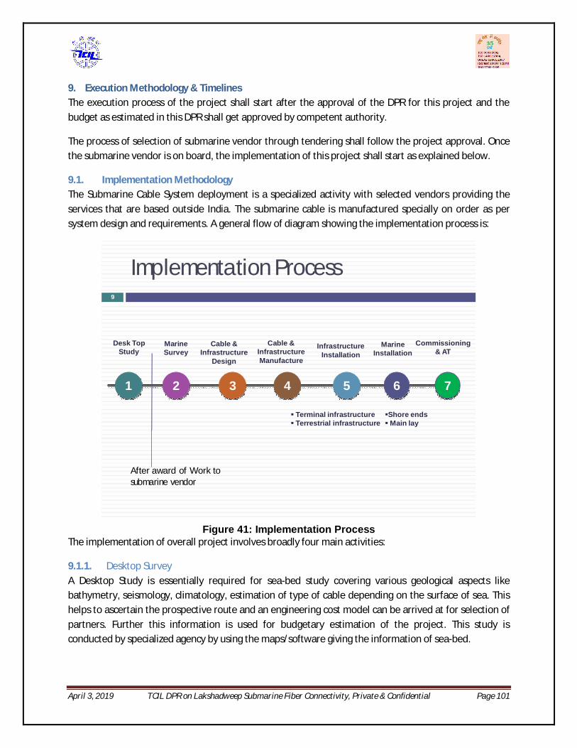
April 3, 2019 TCIL DPR on Lakshadweep Submarine Fiber Connectivity, Private & Confidential Page 101
9. Execution Methodology & Timelines The execution process of the project shall start after the approval of the DPR for this project and the budget as estimated in this DPR shall get approved by competent authority.
The process of selection of submarine vendor through tendering shall follow the project approval. Once the submarine vendor is on board, the implementation of this project shall start as explained below.
9.1. Implementation Methodology The Submarine Cable System deployment is a specialized activity with selected vendors providing the services that are based outside India. The submarine cable is manufactured specially on order as per system design and requirements. A general flow of diagram showing the implementation process is:
Implementation Process9
1 2 3 4 5 6
Desk Top Study
Marine Survey
Cable & Infrastructure
Design
Cable & Infrastructure Manufacture
Infrastructure Installation
Marine Installation
Terminal infrastructure Terrestrial infrastructure
Shore endsMain lay
After award of Work to submarine vendor
7
Commissioning & AT
Figure 41: Implementation Process
The implementation of overall project involves broadly four main activities:
9.1.1. Desktop Survey A Desktop Study is essentially required for sea-bed study covering various geological aspects like bathymetry, seismology, climatology, estimation of type of cable depending on the surface of sea. This helps to ascertain the prospective route and an engineering cost model can be arrived at for selection of partners. Further this information is used for budgetary estimation of the project. This study is conducted by specialized agency by using the maps/software giving the information of sea-bed.

April 3, 2019 TCIL DPR on Lakshadweep Submarine Fiber Connectivity, Private & Confidential Page 102
TCIL floated a tender to select the vendor for conducting Desktop Study of the submarine route for this project.
M/s Ocean Science &Survey had been shortlisted through the tender process.
The report submitted by the vendor is enclosed for reference. It is covering the aspects related to sea-bed study and the data collected during the site visit. The broad scope of work included Identify the potential Cable landing Station (CLS) and Beach Manholes (BMH), Submarine Geology, Climatology, Seismology, Oceanography, Commercial Operations, Restricted Areas and Obstructions, Biological Factors, Regulatory Factors, Site Visit, Route Recommendation & Marine Survey Recommendation.
This report can be made available to bidders at the time of tendering to facilitate them in preparing the bid.
This DPR includes the main findings of both these reports viz. BoQ, CAPEX, OPEX, potential identified sites for CLS & BMH, timelines etc.
9.1.2. Marine Survey Post desktop survey project requires marine survey to be carried out, for arriving at the exact BOQ of equipment to be installed under sea. This activity shall be carried out by the contractor who shall be implementing this project. On the basis of the results of this survey, the entire submarine cable system designing is done.
9.1.3. Execution of works This will involve the below:
a. Permits & Licenses required to start execution b. Submarine Cable Manufacturing & Laying. c. Terminal station Commissioning. d. Acceptance Testing/Third Party audit e. Handover/Takeover (HOTO)
The scope of works for each major head is mentioned in subsequent section.The process for implementing the above activities, involves selection of partner through EOI and tender process.
1. Selection of vendor for desktop survey. 2. Selection of vendor for preparation of EIA report which is required to be submitted for the permissions. .
3. Selection of vendor for marine survey &project execution.
In addition to this, the other activities required to facilitate the implementation of this project is civil works for readiness of infrastructure required in this project i.e. Beach manhole construction, ROW for land cable and laying of duct for same, cable station readiness (AC power plant, electrical connections, false ceiling, access control etc. other utilities like fire detection & alarm, rodent repellants, CCTV access,

April 3, 2019 TCIL DPR on Lakshadweep Submarine Fiber Connectivity, Private & Confidential Page 103
water leakage detection etc. Some of the key permissions required prior to execution of this project like Permit in Principle by DoT, EIA & CRZ being time consuming should be initiated as a parallel activity.
9.2. Scope of Work The marine activities form a critical part of the overall project implementation, ensuring the provision of a reliable and secure submarine link.
The key elements to ensure success of any Submarine Cable project are:
A thorough Cable Route Study.
Accurate data acquisition during the Route Survey.
Detailed analysis of survey data leading to optimum route planning and cable engineering.
Effective installation and burial of the cable.
The figure below gives broad flow of activities involved in a Submarine Cable Project.
Source: http://suboptic.org/Uploads/Files/TuMoB1a.pdf
Figure 42: Activities In a Submarine Project
Planning and Survey Activities
The key activities involved prior to laying the submarine cable in the marine project are:
Desktop Studies Top level cable routing and engineering Realistic cable quantity estimates Site and route evaluations Hazard risk assessments Solution design
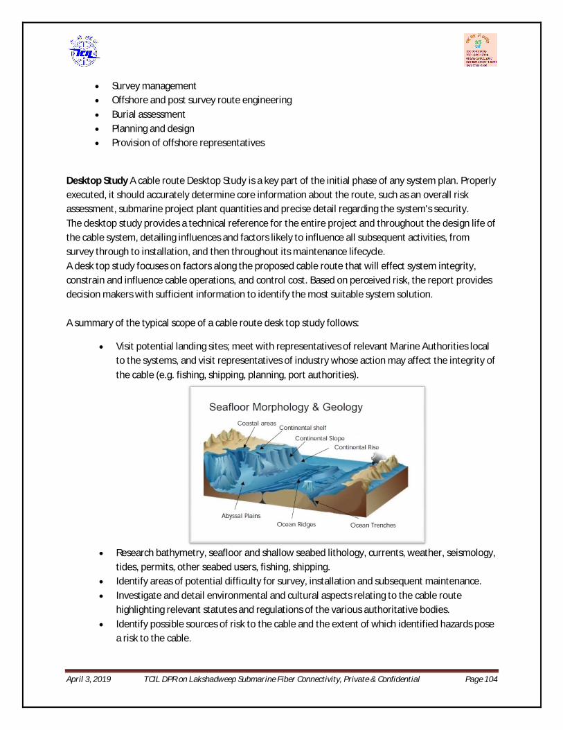
April 3, 2019 TCIL DPR on Lakshadweep Submarine Fiber Connectivity, Private & Confidential Page 104
Survey management Offshore and post survey route engineering Burial assessment Planning and design Provision of offshore representatives
Desktop Study A cable route Desktop Study is a key part of the initial phase of any system plan. Properly executed, it should accurately determine core information about the route, such as an overall risk assessment, submarine project plant quantities and precise detail regarding the system's security. The desktop study provides a technical reference for the entire project and throughout the design life of the cable system, detailing influences and factors likely to influence all subsequent activities, from survey through to installation, and then throughout its maintenance lifecycle. A desk top study focuses on factors along the proposed cable route that will effect system integrity, constrain and influence cable operations, and control cost. Based on perceived risk, the report provides decision makers with sufficient information to identify the most suitable system solution. A summary of the typical scope of a cable route desk top study follows:
Visit potential landing sites; meet with representatives of relevant Marine Authorities local to the systems, and visit representatives of industry whose action may affect the integrity of the cable (e.g. fishing, shipping, planning, port authorities).
Research bathymetry, seafloor and shallow seabed lithology, currents, weather, seismology,
tides, permits, other seabed users, fishing, shipping. Identify areas of potential difficulty for survey, installation and subsequent maintenance. Investigate and detail environmental and cultural aspects relating to the cable route
highlighting relevant statutes and regulations of the various authoritative bodies. Identify possible sources of risk to the cable and the extent of which identified hazards pose
a risk to the cable.

April 3, 2019 TCIL DPR on Lakshadweep Submarine Fiber Connectivity, Private & Confidential Page 105
Identify permits, licenses and other regulatory requirements necessary to install the cable and for the cable to remain in situ along the proposed route.
Recommend routes that do not conflict with existing subsea infrastructure. Route Engineering and survey use the Geographical Information Systems (GIS) databases.
Marine Survey Before finalizing the cable laying route, it is necessary to conduct a detailed survey to investigate the seabed and what lies beneath. Based on the marine survey, the appropriate route for laying the cable (with minimal rocks and with a gradual incline) is identified and the optimum route of the cable is determined.
1. Survey for cable laying (Seabed Surface Survey) Multi-beam depth finder is used to survey the topography of the seabed. With the multi-beam depth finder, it is possible to survey a width of a few kilometers at a time and create a topographical chart of the seabed by processing the data using a computer. With the latest multi-beam system, the surface soil quality distribution of the seabed can also be analyzed from the intensity of the refracted sound waves from the seabed.
2. Survey for cable burying (Seabed Sub-Surface Survey) A survey is conducted to investigate the sub-surface geological layer distribution and the thickness of the sedimentation layer using side-scan sonar and sub-bottom profilers for sections that require the cable to be buried. These surveys use lower sound frequencies than those used for the seabed surface survey. In addition, piston core samplers are used to collect soil samples at regular intervals to ensure that the soil is being investigated correctly.
Post Survey Route Engineering Finally, Post Survey Route Engineering service provides the survey information collected during survey and use it to make the final adjustments to the installation route. These adjustments require a detailed understanding of the practical installation methodologies used by installation vessels, combined with the cable industry GIS software skills to utilise the survey data collected. Performed either on board the survey vessel in near real time or after the survey is completed, the result is the provision of a final route position list (RPL) and Straight Line Diagram (SLD) for installation with precise details of all the necessary cable route events. These typically include; final cable quantities adjusted for correct slack values, cable plant positions, armor type transitions, cable burial start and end points, crossing points and key marine boundary positions.
Permits & Clearances The permits and clearances required prior to laying any undersea submarine cable system are as follows: I. Permit in Principle (PIP) – This is required from the parent ministry i.e DoT to initiate the project.
II. Security Clearance from Ministry of Defense. III. Environmental Clearance – Environment Impact assessment (EIA) IV. NOC from local Authority – ROW/NOC for terrestrial cable laying in islands.

April 3, 2019 TCIL DPR on Lakshadweep Submarine Fiber Connectivity, Private & Confidential Page 106
V. Operational permits to be obtained by implementation agency from customs, Navy, DG (shipping) etc.
Execution of Project The submarine project from installation to commissioning involves a no. of activities contractor is supposed to conduct, as listed below:
Engineering, planning, management and coordination of the implementation of the System.
Survey and study of the landing beaches, terminal Stations, Marine surveys as defined and agreed with Purchasers
Obtain all necessary permits, except for those permits explicitly defined and agreed with Purchasers,
Undersea Cable Route Clearance as defined and agreed with Purchasers,
The loading and testing of the submersible plant and spares on-board the laying ship(s).
The delivery, off-loading and testing of the submersible spares in the selected cable depot(s).
Provision of UJ joint kits for the maintenance of the system.
Pre-lay grapnel runs as defined and agreed with Purchasers,
Design, manufacture, supply and testing of all elements of the System, including spares.
Freighting and delivery of all elements of the System, including spares.
Provision of all materials, test equipment, labor and services, cable laying vessels, support crafts, submersible vehicles, cable plows and as defined and agreed with Purchasers,
Inspection of the buried Marine cable areas as defined and agreed with Purchasers,
Remedial post-lay burial as defined and agreed with Purchasers
Installation of shore end cable protection as defined and agreed with Purchasers,
Pipe-line and cable crossings as defined and agreed with Purchasers,
Provision, Installation and testing of all the elements of the system, including terminal equipment, land sections, submarine segments, ocean grounds and station grounds as defined and agreed with Purchasers, with the exception of construction of the beach man hole(BMH) and the conduits from the BMH to the cable station which will be supplied and installed by Purchasers.
HDD and Guard boats when required
Detailed Electronic survey of cable route and Cable Route Clearance.
Pre-lay Grapnel Run, Laying including Burial as required, Inspection of the buried cable areas, Remedial post lay cable burial.
Permits for Pipelines and Cable Crossings are dealt with in the Terms and Conditions
Perform pre and post crossing notifications to cable and pipeline owners.
Engineering and installation of all required cable or pipeline crossings to comply with the latest applicable recommendations by the International Cable Protection Committee (ICPC).
The shore end and beach works including the necessary cable protections. (The beach works shall include the construction/modification of beach manholes, conduits between beach manhole and the ocean/sea, directional drilling works and any other works as may be necessary).
Test equipment whenever required for testing and commissioning.
April 3, 2019 TCIL DPR on Lakshadweep Submarine Fiber Connectivity, Private & Confidential Page 107
Tool kit per station as required for the implementation and same will be handed over to Purchasers for O&M purposes.
All security measures during all installation phases, including marine installation, land route and terminal installation
Installation and testing of the Data Communication Network (DCN) and Order Wire system (if applicable)
Complete system integration including TSE, MTE, NMS, DCN, and Overall testing and commissioning of the System
Provision of all documentation and Provision of training in the operation and maintenance of the System( as an option)
Supply materials and install cabling to the System demarcation points (Patch panels, Breaker panels etc.) means Purchasers shall provide AC/DC power upto the respective DCPDB and thereafter Contractor shall be responsible for extensions of the same upto their equipment.
Deployment, transportation, accommodation and other requirements of all its employees/ sub-Contractor required for the execution of the Project and for all costs/charges incurred in connection therewith till the date of acceptance.
Deployment of manpower for carrying out the Project, only those manpower resources who are skilled and experienced in their respective fields and who are competent to execute or manage/supervise the Project in a proper and timely manner.
In case of change in its team composition owing to attrition the Contractor shall ensure a reasonable amount of time-overlap in activities to ensure proper knowledge transfer and handover/takeover of Document and other relevant materials between the outgoing and the new member. The existing team member should be replaced with an equally competent substitute from the pool of backup personnel.
Deployment of Electroding generators as defined and agreed with Purchasers and Sub-ducts requirement, if desired by the purchasers.
Project Management
The Project Management is a key activity required in any submarine project to keep it adheres to the schedule as many unforeseen events may arise in a project of this scale. The Project Management Consultant (PMC) would essentially be responsible for:
a. Preparation of Inception Report. This activity has been done by TCIL and report submitted to DoT as Approach Paper.
b. To get the desktop survey of the project in order to come up with authentic requirements on the basis of which tender can be floated. This activity has been done by TCIL. The Desktop Study reports are accompanied with this DPR.
c. Preparation of Detailed Project Report including Desktop Survey Results. This activity is addressed in this DPR by TCIL.

April 3, 2019 TCIL DPR on Lakshadweep Submarine Fiber Connectivity, Private & Confidential Page 108
d. Preparation of EOI & RFP for selection of vendor. There shall be two to three tenders required to be floated for this project 1) EIA assessment 2) Civil Infrastructure readiness 3) Submarine cable laying agency 4) Tender Vetting –technical & legal Expert. This shall include technical specifications and legal clauses vetting by expert agency.
e. Tender floating and evaluation. This shall involve tender normalization by expert agency. f. Award of Works to Agency/vendor. g. Supervision of the project against the set timeline.
Design review and lab demonstration of the technology
Cable loading & assembly
On –board representative during main lay and burial operation. h. Liasoning for obtaining Permits & Clearances wherever required. i. Acceptance testing/Third Party Audit
Factory audit.
Factory Acceptance Tests. j. Hand over Take over (HOTO)
9.3. Timeline Chart The indicative timelines for this project is dived into broad categories a) time required to award the project and b) time required in execution of this project.
9.3.1. Time to Award the Project This is a critical activity and to shorten the time and delay in process of approval, some of the activities like getting EIA study & CRZ clearances can be taken up parallel.
The table showing various targets activity – wise is as below:
S.No Activity Duration Remarks
1. Finalization of DPR
2. Approval of DPR (Telecom Commission & Cabinet)
2 month
3. Tender preparation for (Submarine Project &EIA Study)
1 months Work for permits should start at this point
4. Tender Queries 1 month
5. Bid submission by vendors 1 month
6. Bid Evaluation completed 1 month
7. Placement of Order on vendor 1 month
TOTAL 7 months
April 3, 2019 TCIL DPR on Lakshadweep Submarine Fiber Connectivity, Private & Confidential Page 109
9.3.2. Submarine Execution of Project The submarine cable laying projects broadly involves following activities:
(PIP) Permit in Principle
EIA (Environmental Impact Assessment) & CRZ (Coastal Region Zone) clearance.
Marine Survey
Submarine Cable Manufacturing
Repeater Manufacturing
Loading & Transit
Custom Clearance
Marine Installation
Land Cable Manufacturing
RoW for Land Cable Route
Land Cable Installation
Submarine Equipment Installation at CLS
Acceptance Testing &System commissioning (Go Live)
Each activity has a different duration but may get executed in parallel. The time gauged to execute the project shall be between 18 months to 24 Months from the date of award of project. It is to mention that this is subject to award of work date as the suitable months for laying the submarine cable as indicated by DTS vendor are from December to April depending on the monsoon conditions. A Gantt chart showing the sequence of activities and specific duration is as under:
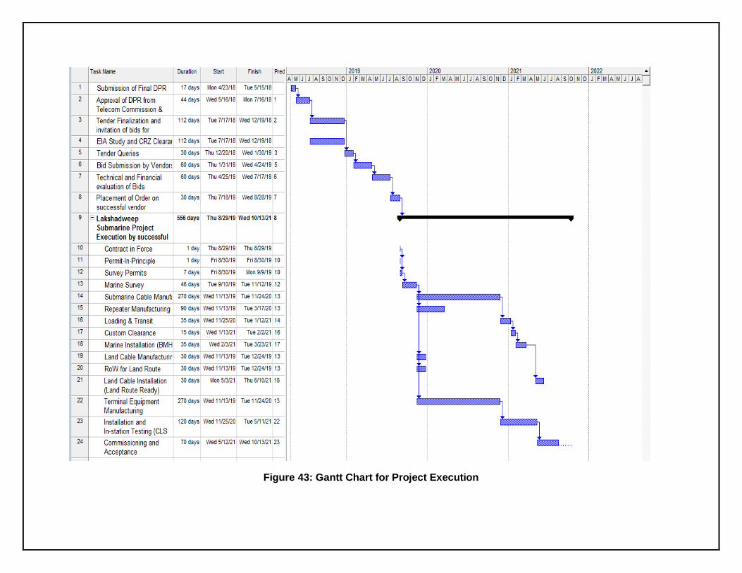
Figure 43: Gantt Chart for Project Execution

10. PERMITS & LICENSES
10.1. Introduction This section describes the currently available information regarding the Permitting requirements in the Lakshadweep area. Information included in this Section has been sourced from:
Existing data and internet data searches Site Visits made to the proposed landing sites and various authorities in March 2018 This Chapter is also covered in DTS Report.
The regulations and permissions discussed are considered to be correct at the time of writing of this section and for the present system.
Governments and Administrative Departments controlling and enforcing the regulations are beset by changes in the requirements caused by the number of cable applications, changing local and national requirements and the political situation at any time. New regulations are also being developed all the time to deal with the submarine cable industry. Discussions with the National Landing parties and regulators should continue to ensure trouble-free survey, installation and maintenance operation.
The Kochi – Lakshadweep route will remain in the Indian territorial waters only.
The maritime territorial claims of India are, as follows:
Territorial Sea * 12 miles Contiguous Zone ** 24 miles Fisheries or Economic Zone 200 miles Continental Shelf 200 miles or the Continental Margin * The Gulf of Mannar and Palk Bay are claimed as historic waters. ** Also considered a Security Zone. The claimed maritime boundaries (updated as of 2014 data) for the KLI route are illustrated in Figure below. The proposed routes lie entirely within Indian Territorial Sea, Contiguous Zone or Economic Zone. It does not cross areas claimed by other countries.

April 3, 2019 TCIL DPR on Lakshadweep Submarine Fiber Connectivity, Private & Confidential Page 112
Figure 44: Maritime claims
10.2. General Permitting Requirements Several different entities have varying responsibilities during the permitting process:
Purchaser - The ultimate owner of the cable system Supplier - The organisation supplying the cable system, which may also actually install the cable Installer/Contractor - The organisation installing the cable (if not above) and/or Any third party contracted by the installer, for example to carry out the survey
For submarine telecommunication cables installations, several types of permissions are typically required:
Operator’s License – The license to operate a submarine cable system. Obtained by the Purchaser (or its in-country subsidiaries as appropriate) and issued by the Licensing Authority (usually a Government Department) of the country in which the installation is proposed
Permits in Principle (PIP) or Route/System/Landing Permits and related EIA – The permission or approval to install a cable system within a country’s territorial seas (TS), possibly its exclusive economic zone (EEZ), and along a terrestrial route to the Terminal Station. Usually issued by a Government Department following consultation. For the purpose of this Section, it is assumed that

April 3, 2019 TCIL DPR on Lakshadweep Submarine Fiber Connectivity, Private & Confidential Page 113
the Installer will work with the Purchaser to acquire all marine permits, whilst the Purchaser nominated Network Provider will be responsible for terrestrial permits.
Operational Permits - Those permits necessary for survey, installation and maintenance operations by the Installer/Contractor who is employed on site (whether marine or terrestrial) to carry out day-to-day operations. Marine operational permits will be the responsibility of the Marine Installer (or its sub contractors) and terrestrial operational permits the responsibility of the Purchaser nominated Network Provider. Undertaking these operational permits assumes that all relevant Permits in Principle have been obtained. Typical marine operational permit applications may include/require any or all of the following:
Covering letter from applicant Letter of introduction from Purchaser or its in-country subsidiary Letter from the Installer for its survey subcontractor for vessel permitting Copy of Purchaser/Installer Contract Letter of appointment of agent by Installer Project schedule/Plan of work (PoW) Project Scope of Work (SoW) Route Position Lists (RPLs) and chartlet(s) Vessel specifications/certificates Vessels P & I Insurance certificates Crew lists with certificates and bio-data/visa application/passport details Foreign registered vessel exemption application (if applicable) Copy of vessel charter agreement duly notarised by Public Notary
Permissions from other interested marine users. Although not detailed in this Section, these will
include crossing permissions from other cable owners or concessions operators. Such permissions may either be a simple written “Agreement to Cross” or a more complex legal “Crossing Agreement”. This choice will be entirely dependent on the requirements of the company whose interests are to be crossed and the negotiations between Purchaser and that relevant company. This also includes agreements to cross Oil and Gas Concession Areas, Military Areas and Agreement with Fisheries Unions (as appropriate).
Survey works can usually commence prior to the Customer obtaining an Operator’s License. Application for installation operational permits and therefore commencement of installation however will not be able to be undertaken until both the Operator’s License and relevant Permits in Principle are in place.
The various permits, licenses and permissions indicated in this section commonly need to be applied for in a set order as each new application often requires that those preceding it have already been approved.
The Permitting requirements are often on the critical path for cable commissioning, and time can frequently be saved if the Purchaser/Supplier/Contractor commences the application process at the earliest possible time.

April 3, 2019 TCIL DPR on Lakshadweep Submarine Fiber Connectivity, Private & Confidential Page 114
Note that the definitive list of Survey and Installation Permitting requirements will only generally be available upon completion of initial discussions with the relevant permitting authorities as part of the permitting process itself.
It is also now common for Environmental Impact Assessments (EIAs) to be requested which may require surveys, studies and assessments, usually limited to Territorial Seas or coastal waters. Such requirements will be stipulated during the “Permits in Principle” process. If issue of any permit is subject to an EIA process, or any other environmental consent, conditions may be attached which require installation vessels to comply with certain environmental criteria. As such, it is advised that all requirements are established prior to operations, and that all works are carried out in compliance with these requirements.
Note that a Permit Matrix is a live document that will undergo continual refinement and updating during the course of a project. It is not possible to fully identify all Permitting requirements in advance as the procedures change from case to case.
10.3. India Permitting The general Permitting Requirements for survey and installation in India are set out below:
10.3.1. Permit in Principle (PIP) Local Body Corporation/administration (for land acquisition, digging of roads, laying of cables and for information on future/planned development in that area) State Government State Government departments related to Highways, Public Works (PWD), Fisheries, Electricity Board, Pollution, Maritime Board, Port & Mercantile etc for information and permission Central Government
Ministry of Telecommunications (Nodal Agency) Ministry of Defense (Agency for survey in Indian EEZ, Territorial waters & Lakshadweep sea besides
construction and other related offshore activities) Ministry of Home Affairs / Ministry of External Affairs (Agency for issue of permit for foreign
national to work in India and operate from vessels in Indian waters) Ministry of Environment (Agency for environmental clearance), etc for permission of cable laying,
operating vessel for survey, installation and maintenance, etc.
The applications for all permission in respect of all the activities involving the above have to be made by the owners of the cable system as the governmental bodies do not entertain requests from contractors, because the government recognizes only the owners for all details of the project. It is estimated that the turnaround period for processing and according permission would take approximately four months from the date of submission of the relevant papers by the owners/applicants to the governmental agencies.
After approval in principle is obtained by the applicants, the other permissions will generally be available in up to 8 weeks.

April 3, 2019 TCIL DPR on Lakshadweep Submarine Fiber Connectivity, Private & Confidential Page 115
10.3.2. Operational Permits It is believed that a CLS will need to be in place in order to get an Operational Permit for cable laying but this will be confirmed in the ongoing permit matrix as the project proceeds. It is understood that the CLS is not essential to obtain a Permit for survey.
Survey and Installation Operation Activities: Operational Permits need to be applied for in parallel with the MOFA Permit if they are not to delay the progress of the project. Once the in-principle approval from MOFA has been received, documents can be submitted to MOFA for both survey and installation activities. Documentation must include:
A project description Survey areas chartlets Route Position Lists (RPLs) Survey crew lists (including passport details) Vessel crew lists (including passport details) Vessel details Vessel certificates Lists of proposed equipment
Project schedule No definitive details on permit application times were secured during the site visits, however the inference from most Government Departments liaised with was that approximately 3 to 4 months would be required to review any application made.
The cable laying operation can be split into two categories: one relating to activities offshore and the second related to activities onshore.
For Offshore Activities: The Govt. of India and Maritime Board are the principal agencies from whom requisite permission has to be taken. The Maritime Board requires details of the project as well as the application to come from the end user and they shall not entertain any intermediaries. The board officials meet once every 3 months and shall study the project/proposal after which they shall reply. The board may levy charges depending on the nature of project and end user. The jurisdiction of the board is from the territorial waters of India (12 Nautical Miles from base line) up to the High Water Line.
For Onshore Activities: As per the Government of India regulations the area falling from High Water Line to about 200 metres come under the Coastal Zone Regulation act and all permits have to be obtained from the Ministry of Environment and Forests. The State Government Information Technology Department is the main regulatory authority for activities on the onshore portion. The location of the proposed beach man hole and the onshore cable route from the beach man hole to the terminal point lie in this region.

April 3, 2019 TCIL DPR on Lakshadweep Submarine Fiber Connectivity, Private & Confidential Page 116
All permissions for all activities for Optic Fiber Cable activities here are to be addressed to the Information Technology Department, which shall act as a single nodal body by coordinating and getting necessary approvals from statutory bodies. The Information Technology Department require full technical specifications of the cables, laying procedure, burial operations etc. along with the details of the route proposed to be followed till the terminal point including contingency plan for re-routing in case of emergency operations.
10.4. Lakshadweep and Minicoy Islands The Lakshadweep and Minicoy Islands are a security sensitive area and Entry Formalities apply. Some areas are closed to visitors and some Nationalities are barred from obtaining visit visas.
The entry to the Lakshadweep and Minicoy Islands is governed by the “LACCADIVE MINICOY & AMINDIVI ISLANDS (RESTRICTIONS ON ENTRY AND RESIDENCE) RULES, 1967”
10.5. Permitting Procedure & Lead-time Summary The summary provided below should be regarded as indicative only; actual Permitting times will depend on the status of the applicant and the urgency with which Permitting is pursued. However it should be stressed that Permitting is a time consuming process and if insufficient time is allowed for this the project will be delayed and both survey and installation activities risk being forced into periods of the year when the weather is unfavourable, with a resultant increase in costs and potential adverse effect on the final cable installation.
Permit Title or Description
Permit Granting Authority and POC
Details
Application Requirements (Supporting Documentation)
Estimated Duration for Application
Approval Permit in Principle (PIP) permission for the cable laying project
Ministry of Communication DoT Govt. of India
Submission of the application by Purchaser
2 Months
RSEE (Research, Survey, Exploration and Exploitation)
Ministry of Defence Naval Headquarters (MOD)
Attach to the application: A cover letter, Copy of the Permit-in-Principle:, Contract copy (between operator & subcontractor), LOA / LOI between sub-contractor and vessel owner, vessel route map, map and coordinates, vessel details
3 Months
MOHA clearance Ministry of Home Affairs (MOHA)/ Intelligence Bureau
Copy of the Permit-in-Principle: Form with personal details and signature along with clear copy of passport and 4 passport size latest photographs
4-5 Months
Specified Period License (SPL)
DG Shipping Please note that DGS will not issue SPL to any vessel if its age is more than 25 years
15 Days
INSA Clearance Indian National Ship Owner's Association
Vessel details, Work required, PIP 2 Weeks

April 3, 2019 TCIL DPR on Lakshadweep Submarine Fiber Connectivity, Private & Confidential Page 117
Permit Title or Description
Permit Granting Authority and POC
Details
Application Requirements (Supporting Documentation)
Estimated Duration for Application
Approval Naval Clearance Flag Officer
Defense Advisory Group FODAG
Copy of the Permit-in-Principle: Application with required docs such as copies of ships statutory certificates (annually endorsed), Copy of the RSEE application, Copy of Operator's request Letter along with copy of the MOHA clearance for crew members on board, Two colour ship photograph ETC, should be submitted to authority along with request letter from Operator and accordingly Naval team will board the vessel for inspection and security clearance will be issued next day after the inspection
2 Weeks
Table 1: Operational Permitting Matrix India and Lakshadweep Islands
Further details and application formats for PIP, MOD, MOHA are given in Appendix D.
No. Regulatory Permit/ Noc
Concerned Agency Activities Involved Time Frame from Start
(weeks) 1 Development
Plan Remarks Deputy Commissioner at respective location
Assess permitability as per area planning 0-10
2 Recommendation under Coastal Regulation Zone Act for project activities in CRZ Areas
Lakshadweep Coastal Zone Management Authority
Survey route to be authenticated by a Govt. approved agency.
0-16
EIA and EMP Preparation including CRZ management plan for the Project including baseline study with respect to physical, biological and socio-economic environment, Coordination with Govt. Approved Agency with respect to CRZ Survey Submission of Application to CZMA along with DP Remarks, CRZ Survey Maps, CRZ management plan, EIA/EMP
16-19
Presentation to A&NCZMA and clarifications to committee
19-29
Recommendation from A&NCZMA 29-34 3 Clearance under Ministry of Submission of Application to MoEF with all 34-36

April 3, 2019 TCIL DPR on Lakshadweep Submarine Fiber Connectivity, Private & Confidential Page 118
CRZ Notification Environment and Forests (MoEF), New Delhi
requisite details Presentation to MoEF 36-46 CRZ Final Approval 46-54
4 NOC from Fisheries Department
Commissioner of Fisheries, A&N
Application to CoF with Project details 0-16
Follow-ups and Clarifications to the Department
Note : Typical time frame to get these Permits is between 12 to 14 months
Table22: Environment related Permits for Cable Landing in Lakshadweep Islands
Among the above list of clearances , the two clearances which can be taken prior to award of work to contractor is the Permit in Principle (PIP) from DoT and EIA clearance which shall require to indulge a specialize agency to conduct the environmental impact study of this project and may take approximately a year.
The other clearances shall be taken by the contractor who will be awarded the project.
April 3, 2019 TCIL DPR on Lakshadweep Submarine Fiber Connectivity, Private & Confidential Page 119
11. RISKS & HAZARDS The probable risks that this project can face can be categorized in two categories:
1. Risks prior to start of execution (while award of work) 2. Risks while execution of project
Some of the Risks which this project can face prior to start of the project are:
Time line to award the work
Some of the probable events which can cause the delay in award of work are:
Delay in approval of project Delay in tendering to select the submarine vendor. Delay in getting CRZ clearance for the project
The risks can be covered by carrying out activities parallel.
The various main risks that may be encountered while execution of this project are bulleted below:
Adverse sea conditions, particularly from June to August
Cyclones, with peak activity from April to December, with most activity in October/November
Hydrocarbon concessions with likely exploration activity
Submarine cables, including several IS cables converging on Chennai and both IS and Planned cables in the Bay of Bengal
Several wrecks on the continental shelves
The greatest risk to cable integrity in the KLI region is believed to be from trawling activities; there is also potential risk from tsunami, anchoring activities, hydrocarbon operational areas and piracy.
Trawling is carried out by both by licensed and illegal fishing vessels, to reported water depths of up to 750 m. Although burial to 1 m below the seabed out to 1,000 m WD will provide good protection from this activity, expected ground conditions in the Lakshadweep Islands will preclude effective burial. Where cable burial is not possible, the seabed will also be unfavourable for trawling, limiting the risks of leaving the cable exposed on the seabed.
A threat from tsunami is present at all landfalls. The design and positioning of the BMH structures should take into account the possibility of tsunami damage over the lifetime of the cable system.
The anchoring risks and shipping risks generally are believed to be highest near Kochi but also significant near the local anchorages at the islands. A review of burial requirements and the inshore routes is recommended when survey data has been analysed for signs of anchoring.
Hydrocarbon exploration is a high risk in OCBs. Liaison with the operators is recommended before survey and installation and throughout the life of the cable system.

April 3, 2019 TCIL DPR on Lakshadweep Submarine Fiber Connectivity, Private & Confidential Page 120
The routes avoid a Firing Practice Area near Kochi and FADs around the islands.
The best months for survey and installation are December to April, but note that there is a risk from tropical cyclones from April to December with peak activity in October/November.
The DTS study has shown that there are no technical feasibility issues that cannot be addressed by well-understood technologies and procedures; although there are high risks associated with the cable planning and installation, no high threat to the cable routing or to its long term viability has been identified.
The risks and hazards have been broadly classified and tabulated below for ready reference.
LEVEL OF CONCERN
High Available data indicate a significant risk and continuing concern from this source
Medium Available data indicate a possible risk that needs to be better assessed
Low Available data indicate that while present continuously or intermittently in some areas, this concern is unlikely to affect cable integrity
RISK SOURCE HAZARD MITIGATION ACTION ESTIMATED RESIDUAL RISK LEVEL
Seismicity Earthquakes shock Suitable BMH, CLS and land based cable duct design
Low
Tsunami triggered by earthquake or volcanism
Inundation of BMH and CLS, movement of inshore cable. All landfalls exposed
Suitable BMH and CLS location and design; use of AP.
Moderate
Marine Volcanism and Hydrothermal Vents
Magma or hot water issue from vents on the island slopes. Risk of thermal damage to cable or repeater
Avoid any vents found during survey.
Low
Mass Movements Risk of earthquake- or cyclone-triggered down-slope sediment movement, particularly on continental slope off Kochi
Avoid canyons and route directly down slope
Low
Active Faulting Risk of cable shear None required Low

April 3, 2019 TCIL DPR on Lakshadweep Submarine Fiber Connectivity, Private & Confidential Page 121
Morphodynamics Risk of wave or current induced sediment movement. Likely during strong monsoon winds at all landfalls
Suitable armour selection; avoid Sandwaves whenever possible and cross perpendicular to strike where crossings are unavoidable. Use AP inshore
Low
Scour Risk of current induced cable strum and abrasion in areas where cable is surface laid and there are significant currents. Potential risk on continental shelf and slope wherever burial is impossible due to rock outcrops or steep slopes
The cable armour types selected are designed to withstand potential suspension. Installation techniques, slack management and route engineering all contribute to reduce the likelihood of suspended cable. In deeper areas, LWP cable has been found to provide sufficient protection.
Low
Rock Exposure and subcrop
Rock and/or coral outcrops expose the cable to risk of abrasion and suspension and are a hazard to ploughing. Boulders previously encountered on Indian continental slope; Lakshadweep Islands have extensive rock and coral reefs
Suitable armour selection; conduct thorough survey and plough with care
High
Gas Short steep slopes associated with pockmarks may cause plough instability. Risk of overburial in very weak sediments. Risk to vessels if large blowouts occur
Pockmarks are avoided where possible post-survey. Additional care is required when ploughing through pockmark areas
Low
Table 23: Submarine Physiography and Geology Risk Assessment
RISK SOURCE HAZARD MITIGATION ACTION ESTIMATED RESIDUAL RISK LEVEL

April 3, 2019 TCIL DPR on Lakshadweep Submarine Fiber Connectivity, Private & Confidential Page 122
RISK SOURCE HAZARD MITIGATION ACTION ESTIMATED RESIDUAL RISK LEVEL
Meteorology Heavy downpours during rainy season and possible flooding may hinder land work.
Avoid monsoon rain seasons during survey and installation.
Low
Meteorology/ Waves
Both monsoons produce adverse conditions for much of the year. Tropical Cyclones are a higher risk from April to December in the Laccadive Sea
If possible work during period December to April. Provide additional cable protection in surf zones. Ensure vessels have adequate Cyclone warning systems
Medium
Currents Surface currents in the area are generally low but can reach around 1 m/sec on the west coast of India. Solitons are a high risk in the Laccadive Sea. Tidal currents of up to 1 m/sec are reported in the Lakshadweep Islands
Vessel operators should exercise due care during survey and installation
Low
Seawater temperature and salinity
High surface salinity variability between seasons (monsoons water run-off)
More frequent sound velocity measurements may be required for multibeam calibration offshore Kochi
Low
Table 24: Environmental Factors Risk Assessment
RISK SOURCE HAZARD MITIGATION ACTION ESTIMATED
RESIDUAL RISK LEVEL
Trawling Trawling to around 750m on Indian continental shelves
Burial up to 1m out to 1,000 m WD; up-armouring to DA on continental shelf in areas of anticipated poor burial. Ensure cable is shown on charts after installation
High

April 3, 2019 TCIL DPR on Lakshadweep Submarine Fiber Connectivity, Private & Confidential Page 123
RISK SOURCE HAZARD MITIGATION ACTION ESTIMATED RESIDUAL RISK LEVEL
Tuna longlining Hooking un-armoured cable during installation
Liaise with fishing communities, make arrangements that long lines will not be deployed during installation. Use long line cutter during cable installation
Low
FADs/ Traps Crushing by anchor weights, obstruction by seabed installation, float and fishing vessels.
Avoided charted FADs. Check for possible changed FAD locations and new deployments during survey
Moderate
Shipping and Anchoring
All charted vessel anchorage areas have been avoided
Bury the cable to 1 m on the continental shelf. Promulgate cable positions on charts
Moderate
Hydrocarbon Concessions
There are widespread concession blocks and exploration poses a risk of obstruction during survey and installation. Oil and Gas exploration and exploitation will continue in the region over the life of the cable.
Liaise with authorities and Concession holders to identify potential developments. Promulgate cable positions on charts as soon after installation as possible.
Low
Mineral/Sand Extraction
Possible illegal extraction near landfalls
Use DA cable and AP in inshore areas
Low
Dumping, Dredging and Reclamation
No current dumping, dredging or reclamation has been identified near the routes
Liaise with authorities during the life of the cable to ensure future projects do not affect the installation
Low
Submarine Cables Unavoidable crossings of In-service and OOS cables
Survey and install with care. Liaise with authorities and Cable owners and obtain crossing agreements ahead of installation
Low
Military Activities Route passes close to firing practice area east of Kochi. Risk of disruption to survey and installation. Risk of encountering UXO.
Liaise with local military during Permitting; check Notices to Pilots for any Exercise announcements. Review safety of burying through areas with UXO
Medium
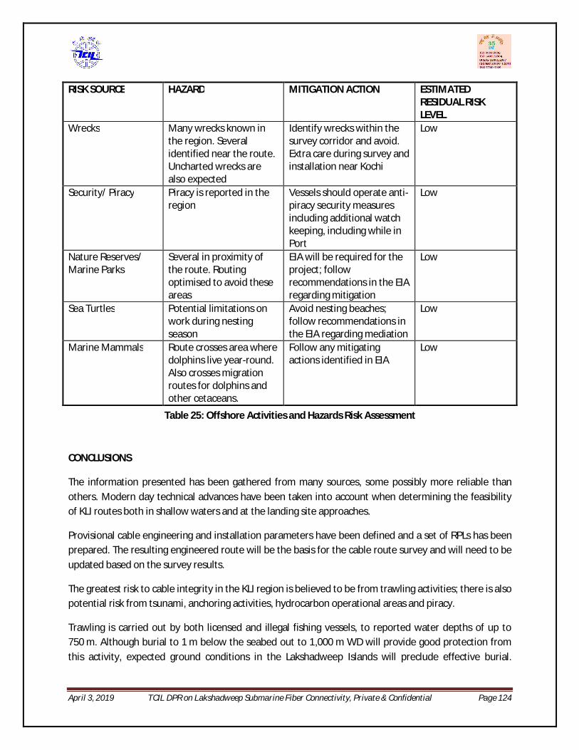
April 3, 2019 TCIL DPR on Lakshadweep Submarine Fiber Connectivity, Private & Confidential Page 124
RISK SOURCE HAZARD MITIGATION ACTION ESTIMATED RESIDUAL RISK LEVEL
Wrecks Many wrecks known in the region. Several identified near the route. Uncharted wrecks are also expected
Identify wrecks within the survey corridor and avoid. Extra care during survey and installation near Kochi
Low
Security/ Piracy Piracy is reported in the region
Vessels should operate anti-piracy security measures including additional watch keeping, including while in Port
Low
Nature Reserves/ Marine Parks
Several in proximity of the route. Routing optimised to avoid these areas
EIA will be required for the project; follow recommendations in the EIA regarding mitigation
Low
Sea Turtles Potential limitations on work during nesting season
Avoid nesting beaches; follow recommendations in the EIA regarding mediation
Low
Marine Mammals Route crosses area where dolphins live year-round. Also crosses migration routes for dolphins and other cetaceans.
Follow any mitigating actions identified in EIA
Low
Table 25: Offshore Activities and Hazards Risk Assessment
CONCLUSIONS
The information presented has been gathered from many sources, some possibly more reliable than others. Modern day technical advances have been taken into account when determining the feasibility of KLI routes both in shallow waters and at the landing site approaches.
Provisional cable engineering and installation parameters have been defined and a set of RPLs has been prepared. The resulting engineered route will be the basis for the cable route survey and will need to be updated based on the survey results.
The greatest risk to cable integrity in the KLI region is believed to be from trawling activities; there is also potential risk from tsunami, anchoring activities, hydrocarbon operational areas and piracy.
Trawling is carried out by both licensed and illegal fishing vessels, to reported water depths of up to 750 m. Although burial to 1 m below the seabed out to 1,000 m WD will provide good protection from this activity, expected ground conditions in the Lakshadweep Islands will preclude effective burial.

April 3, 2019 TCIL DPR on Lakshadweep Submarine Fiber Connectivity, Private & Confidential Page 125
Where cable burial is not possible, the seabed will also be unfavourable for trawling, limiting the risks of leaving the cable exposed on the seabed.
A threat from tsunami is present at all landfalls. The design and positioning of the BMH structures should take into account the possibility of tsunami damage over the lifetime of the cable system.
The anchoring risks and shipping risks generally are believed to be highest near Kochi but also significant near the local anchorages at the islands. A review of burial requirements and the inshore routes is recommended when survey data has been analysed for signs of anchoring.
Hydrocarbon exploration is a high risk in OCBs. Liaison with the operators is recommended before survey and installation and throughout the life of the cable system.
The routes avoid a Firing Practice Area near Kochi and FADs around the islands.
The best months for survey and installation are December to April, but note that there is a risk from tropical cyclones from April to December with peak activity in October/November. The study has shown that there are no technical feasibility issues that cannot be addressed by well-understood technologies and procedures. However it should be remembered that, whilst every attempt was made to collate all the data available to design a secure route, additional data may be obtained at any time that may require route alterations. Liaison with other stakeholders carrying out activities that could impact on the cable should be continued over the lifetime of the system.

April 3, 2019 TCIL DPR on Lakshadweep Submarine Fiber Connectivity, Private & Confidential Page 126
12. Project Management Consultant
12.1. Project management aspects The Project Management Consultancy services are critical in the project of this scale where the system is designed and implemented by a expert agency, permits are required from Indian government, liasoning with local authorities is required for successful commissioning of this project. The project management activities for the cable owner for this project would be broadly four-faceted as following;
i. Tendering (tender formation, evaluation, equalization, providing contractor clarifications, and contract formation)
ii. Permits iii. Supply contract management iv. Cable station and infrastructure readiness v. Roll out and O&M readiness
Tendering (tender formation, evaluation and contract formation)
The Tendering tasks would comprise of preparing tender documents, receiving responses, analyzing, equalizing and evaluating the offers as per developed evaluation criteria. After the technical evaluation and offer equalization, the winning tenderer is decided. The system description submitted by the (winning) tenderer is then scrutinized in detail, the unaddressed issues and requirements are discussed and finalized and the contract document is developed for signature. After fulfillment of certain commercial conditions by the supplier, the contract comes into force. The tender documents for submarine systems, as per standard international practice, comprise of various document packages, important of which are; Commercial terms and conditions, Technical package containing specifications, network requirement, design and performance
parameters, installation and marine activity procedures, support and warranty procedures, acceptance procedures etc.
Price schedules The entire process from tender formation till contract signature might take 4-6 months. Permits The activities would require to be commenced much before supply contract comes into force. These would typically involve, understanding the permit requirements completely, putting a plan in place to acquire the required permits duly considering risks and contingency, initiating action according to the plan and constant follow-up with the concerned third party (if engaged) or the government authority. Timey escalation and engagement with correct follow-up at senior level forms the key for timely acquisition of permits.

April 3, 2019 TCIL DPR on Lakshadweep Submarine Fiber Connectivity, Private & Confidential Page 127
A crucial impact of any delays incurred in securing permits that are the responsibility of the owners, may be used as an opportunity by the suppliers as a reason for cost increase and delays in project implementation. Hence it important that firstly, the scope and timelines of permits are agreed with the supplier during contract formation with great care and once agreed all efforts should be made to obtain the subject permits well in time. As mentioned in Part 1, there are two main permits under cable owner responsibility; PIP (Permit-in-Principle) CRZ clearance Among the two, CRZ is of utmost importance, as it is historically known to have taken several months to be available and for this particular project since the Lakshadweep Islands are environmentally sensitive zones, hence the time taken could be even more. An EIA would also need to be performed during the course of seeking the permits As already suggested, CRZ clearance must be initiated in parallel with tendering stage. The PIP need to be available within a couple of weeks of supply contract coming into force,so that the chosen supplier could then use it to timely initiate other operational permits without having an impact on their plan of work, (marine survey being the first ones). Besides PIP and CRZ, the cable owners would be routinely required to sign the documents of various operational permits too during the project execution cycle, as the permits can be issued by the agencies only in the name of the cable owner. The supplier would perform the tasks of processing applications, submitting and follow-up with the require agencies but all correspondence would be routed through the cable owner. Hence prior understanding of process and requirements would help achieve better coordination with the supplier. Supply contract management These activities would commence with contract CIF and would require constant engagement with the chosen supplier, monitoring the progress along an agreed plan of work, deviations from schedule and day-to-day management of issues that come up. The important thing here would be to contain cost escalations, and make sure that the project is executed in the agreed time frame. In addition, many technical visits would also need to be undertaken immediately after supply contract comes into force and may continue from time to time till the project commissioning. These may include; System design review and acceptance Lab demonstration Factory audit &acceptance tests Cable acceptance and loading Various stages of on-site testing for approving completion and acceptance of milestones as per
specs Ship representatives during survey &cable lay operations

April 3, 2019 TCIL DPR on Lakshadweep Submarine Fiber Connectivity, Private & Confidential Page 128
Besides the technical visits, the technical team would be required to develop various test plans, tests schedules, review detailed engineering specifications of manufacturing and perform remote verification of many manufacturing tests. Their acceptance would lead to payment of certain billing milestones. For carrying out these activities, professionals having sound knowledge and experience on submarine technical and marine aspects and testing would be needed from the contract in force time. The duration may be right from the contract in force till the system commissioning and clearance of deficiencies. Technical support would also be required during the supply contract tendering and contract formation stages, as explained in section. Cable station and infrastructure readiness This is one important aspect of the project whose responsibility is usually on the cable owner, and in case of Lakshadweep project would require significant pre-planning for every landing station site before the supply contract is in force, in order to assess the options available and accordingly decided on the course of action. This activity would concentrate on those aspects of the project that are not part of the supplier responsibilities but determine the timely implementation of supplier’s scope within the contractual plan of work. As already detailed in the civil construction of cable station, BMH and land route would need to carried out keeping in mind the operational requirements and standards of submarine cable and specifics of this project. For carrying out these activities, a joint team of professionals experienced on submarine project implementation along with civil and infrastructure aspects and utility providers are required. The duration of activity might be of several months and would require constant on-site presence during planning construction phases. Station installation supervision The presence of cable owner’s representative (preferably a future O&M staff) is required to receive and verify the consignments and also supervise and support the activities of the supplier onsite team at every landing site till the commissioning of the system. The consignments would be shipped in the name of the cable owner, as the cable owner would be the IOR (Importer on record).Custom clearance formalities would again require paper work to be routed through cable owner and co-ordination with supplier’s logistics team and custom house agents. Marine activity supervision The marine activities need to be supervised by cable owner representatives and would require experienced professionals for onboard representative during survey and lay operations. Reviewing of daily on-board meetings and supervising that all actions were as per standard procedures and no hazardous events went unreported are usual tasks of onboard representatives.T hey are also authorized

April 3, 2019 TCIL DPR on Lakshadweep Submarine Fiber Connectivity, Private & Confidential Page 129
to take decisions regarding survey or lay variations or processes when unforeseen scenarios are encountered and document them for raising with suppliers. Roll out and O&M readiness There are several important tools and systems that need to be in place to ensure smooth launch of O&M on the day of its commissioning. These may include;
O&M Team hiring and training NOC establishment NOC portal development NOC procedures SLA defining O&M procedures
Ideal time to commence most of the O&M readiness related tasks is when half-way stage of project execution is reached but a few among these might be either slightly brought forward or delayed. O&M Team hiring and training
Complete manpower required for running technical operations at cable station and NOC should be preferably on board at least 2 months before the system commissioning. A part of it should preferably be involved during equipment installation and testing in order to carry forward familiarity from the project stage to the O&M stage. The supply contract would cover training requirements for the O&M team and these would need to be scheduled during the last stages of project execution, along with the progress of segment readiness in order to cover hands on training portions on the actual system. Besides, the O&M team would also need to be provided training on the NOC and O&M procedures and familiarity with the portal.
NOC establishment The NOC location should preferably be decided before the contract signature or as late as till few months after the contract comes into force. A back-up NOC (BNOC) location should also be decided to act as disaster recovery site. For Lakshadweep cable system, Kochi and Kavaratti would be the two sites for the main and back-up NOC. The NOC infrastructure depending upon its customer type would require a portal, communication means (telephone lines & internet connection) and adequate manpower for 24x7 helpdesk support to all cable stations as well as the customers and NOC seating arrangement with some large display screens. The equipment supplier would provide the NMS for installation at the NOC and BNOC site along with the DCN network. The NOC procedures and manpower requirement and hierarchy would be developed by the agency entrusted with the responsibility for running the system O&M in view of the SLA conditions.

April 3, 2019 TCIL DPR on Lakshadweep Submarine Fiber Connectivity, Private & Confidential Page 130
The procedures should be ready and manpower on board at least a month before the system commissioning. NMS development The NOC would provide following services 24x7 helpdesk support for complaint management Fault management Performance management Capacity activation Reporting Coordination with AMC suppliers Inventory management For efficient way of rendering these services and the proper record upkeep, a cable system (NOC) portal would need to be developed. The work for portal development must start at least 10 months form the system commissioning in order to be ready by system commissioning. Its scope and deliverables would need to be developed by the O&M team (or agency) NOC procedures
The procedures would be the standard operating procedures for all the services listed in the sections above. These need to be developed by the O&M team and would need to be ready by system commissioning.
SLA defining Assuming that the system O&M would be run by a third party responsible for providing complete manpower and also running the entire O&M roles, the O&M SLA could be broadly developed on following aspects; Manpower availability parameters Customer support performance parameters Network availability parameters Planned maintenance parameters Inventory management parameters Each of these SLA categories would be required to have benchmark criteria, penalty and incentives schemes and also exclusion scenarios. The O&M team (or the agency) would be required to agree to the SLA. It is important to note that the planning for the manpower and other supporting resources for the O&M team would need to be aligned with the level of SLA being required form the O&M team (or agency).

April 3, 2019 TCIL DPR on Lakshadweep Submarine Fiber Connectivity, Private & Confidential Page 131
12.2. Structure - Project Management Unit The structure of the PMU shall vary with different phases of the project i.e. award phase, implementation phase and maintenance phase.
The award phase shall be lead by a senior officer with two team leads for preparation of tender, co-ordination with legal and financial experts, an expert agency services may need to be hired to review the technical specifications and tender normalization.
The implementation phase shall also involve same team in addition to team of Engineers to carry out site visit required for acceptance testing,factory audit . In this phase also, services of submarine expert agency may be required to vet the system design matrix.
The maintenance phase shall involve Staffing for cable station and NOC. A team strength of 32 individuals (over 3 skill level set) have been considered for running the technical operations at all the cable landing sites along with NOC. The support staff strength of (security and utility supervisors) of 17 has been considered.
Station L3 (Technicians)
L2 (Engineers) L1 (Manager) Security / Support
Total
Station Kochi 4 1 1 4 10 Station Kavaratti 4 1 1 4 10
Other stations 12 0 0 9 21
NOC 4 2 1 0 6 BNOC 1 1 0 0 2 Total 25 4 3 17 49
Table24: Proposed staffing level
12.3. Ownership Issues Funding Methodology Although the telecom and broadband penetration for Lakshadweep islands would increase after laying of submarine OFC cable, the estimated expenditure to be incurred for laying the submarine fiber and further maintaining it is huge. The population of Lakshadweep being only ~ 76,000 the same cannot be met by the current revenue realizations. There is no business case for any telecom operator to take up laying of submarine cable to Lakshadweep islands. Therefore, the strategic funding of CAPEX and further OPEX required for this project is essential.
The project may be implemented in two ways:
1) The RFP to implement the project invites service providers holding NLD license to implement own, operate and maintain the submarine connectivity system to Lakshadweep Islands.
However, in this approach there are following issues:

April 3, 2019 TCIL DPR on Lakshadweep Submarine Fiber Connectivity, Private & Confidential Page 132
USF may only be able to directly provide the entire CAPEX. In case it does, the assets so created have to be owned by the USOF.
The second important aspect is the security concern and Lakshadweep islands are having Defense presence and from national security point of view, it is advisable that the project lies in the hands of government or any government body like BBNL or Lakshadweep Administration.
2) The final system funded by USOF be handed over to Bharat Broadband Nigam Limited (BBNL) or any
SPV thus created which as a government arm own the system and lease bandwidth to telecom operators on non-discriminatory basis as per the tariff rates set by TRAI subject to market conditions. In this manner, one fiber pair may be directly provided to meet the Defense requirements.
12.4. Commercial Issues As Lakshadweep has limited population, the Telecom service providers (TSPs) may not like to invest their owing to increase in cost of service provision due to addition of transportation charges and less Return on Investment (RoI).
The commercial utilization of the network by the TSPs can still be ensured if the passive telecom network elements are shared like mobile tower, Equipment room. BSNL has a presence in every island therefore it will be prudent to mandate BSNL to share its infrastructure. In return USOF can provide right of operation and access to created submarine telecom infrastructure.
As USOF has funded the project so to create a level playing field for all TSPs , the USOF needs to define the bandwidth leasing charges subsidized to encourage telecom penetration by other TSPs. This may be defined as a percentage of bandwidth leasing rates defined by TRAI.
