detailed specifications of the satellite radio interfaces ...!pdf-e.… · radio interfaces of...
TRANSCRIPT
Recommendation ITU-R M.2047-0(12/2013)
Detailed specifications of the satelliteradio interfaces of International Mobile
Telecommunications-Advanced (IMT-Advanced)
M SeriesMobile, radiodetermination, amateur
and related satellite services

ii Rec. ITU-R M.2047-0
Foreword
The role of the Radiocommunication Sector is to ensure the rational, equitable, efficient and economical use of the radio-frequency spectrum by all radiocommunication services, including satellite services, and carry out studies without limit of frequency range on the basis of which Recommendations are adopted.
The regulatory and policy functions of the Radiocommunication Sector are performed by World and Regional Radiocommunication Conferences and Radiocommunication Assemblies supported by Study Groups.
Policy on Intellectual Property Right (IPR)
ITU-R policy on IPR is described in the Common Patent Policy for ITU-T/ITU-R/ISO/IEC referenced in Annex 1 of Resolution ITU-R 1. Forms to be used for the submission of patent statements and licensing declarations by patent holders are available from http://www.itu.int/ITU-R/go/patents/en where the Guidelines for Implementation of the Common Patent Policy for ITU-T/ITU-R/ISO/IEC and the ITU-R patent information database can also be found.
Series of ITU-R Recommendations
(Also available online at http://www.itu.int/publ/R-REC/en)
Series Title
BO Satellite delivery
BR Recording for production, archival and play-out; film for television
BS Broadcasting service (sound)
BT Broadcasting service (television)
F Fixed service
M Mobile, radiodetermination, amateur and related satellite services
P Radiowave propagation
RA Radio astronomy
RS Remote sensing systems
S Fixed-satellite service
SA Space applications and meteorology
SF Frequency sharing and coordination between fixed-satellite and fixed service systems
SM Spectrum management
SNG Satellite news gathering
TF Time signals and frequency standards emissions
V Vocabulary and related subjects
Note: This ITU-R Recommendation was approved in English under the procedure detailed in Resolution ITU-R 1.
Electronic Publication Geneva, 2014
ITU 2014
All rights reserved. No part of this publication may be reproduced, by any means whatsoever, without written permission of ITU.

Rec. ITU-R M.2047-0 1
RECOMMENDATION ITU-R M.2047-0
Detailed specifications of the satellite radio interfaces of International Mobile Telecommunications-Advanced (IMT-Advanced)
(2013)
Scope
This Recommendation identifies the satellite radio interface technologies of International Mobile Telecommunications-Advanced (IMT-Advanced) and provides the detailed radio interface specifications.
These radio interface specifications detail the features and parameters of the satellite component of IMT-Advanced. This Recommendation includes the capability to ensure worldwide compatibility, international roaming and access to high-speed data services.
Keywords
Satellite; radio interface; IMT-Advanced; SAT-OFDM; BMSat.
Abbreviations/Glossary
3GPP Third generation partnership project
ACK Acknowledgement
AI Acquisition indicator
AM Acknowledge mode
AMC Adaptive modulation and coding
ARQ Automatic repeat request
AS Access stratum
3GPP 3rd Generation partnership project
BCCH Broadcast control channel
BCH Broadcast channel
BPSK Binary phase shift keying
BSR Buffer status reporting
CCCH Common control channel
CCE Control channel element
CCSA China communications standards association
CFI Control format indicator
CGC Complementary ground component
CoMT Coordinated multi-point transmission
CP Cyclic prefix
CQI Channel quality information
CRC Cyclic redundancy check
CRS Cell-specific reference signals
C-RNTI Control-radio network temporary identifier

2 Rec. ITU-R M.2047-0
CSI Channel state information
DCCH Dedicated control channel
DCI Downlink control information
DFT Discrete Fourier transform
DFTS-OFDM Discrete Fourier transform-spread orthogonal frequency division multiplexing
DL Downlink
DL-SCH Downlink shared channel
DM-RS Demodulation reference signals
DSAT-eNB Donor satellite eNodeB
DTCH Dedicated traffic channel
ECR Efficient code rate
EF Envelop fluctuation
EIRP Equivalent isotropically radiated power
E-PPCH Enhanced physical paging channel
E-USRA Evolved universal satellite radio access
E-USRAN Evolved universal satellite radio access network
FEC Forward error correction
FDD Frequency division duplexing
FDMA Frequency division multiple access
FFR Fractional frequency reuse
FSTD Frequency switched transmit diversity
GBR Guaranteed bit rate
GEO Geostationary earth orbit
GNSS Global navigation satellite system
GPS Global positioning system
GSO Geostationary-satellite orbit
G/T Antenna gain-to-noise temperature
GTP General packet radio service tunnelling protocol
HARQ Hybrid ARQ
HEO Highly elliptical orbit
HI HARQ indicator
IBIC Inter-beam interference coordination
ID Identity
IFFT Inverse fast Fourier transform
IMAP Internet message access protocol
IMT International Mobile Telecommunications
Rec. ITU-R M.2047-0 3
IP Internet protocol
ITS Intelligent transport systems
IU Interleaving unit
L2 Layer 2
LCID Logical channel identifier
LEO Low earth orbit
LHCP Left hand circular polarisation
LTE Long term evolution
MAC Medium access control
MBMS Multimedia broadcast and multicast service
MBSFN Multicast/broadcast over a single frequency network
MCCH Multicast control channel
MCH Multicast channel
MCS Modulation and coding scheme
MEO Medium earth orbit
MES Mobile earth station
MIMO Multiple input and multiple output antennas
MME Mobility management entity
MMEC Mobility management entity code
MSS Mobile satellite service
MTCH Multicast traffic channel
NACK Negative-acknowledgement
N/A Not applicable
NAS Non-access stratum
NDI New data indicator
OAM Network operations and maintenance
OFDM Orthogonal frequency division multiplexing
OFDMA Orthogonal frequency division multiple access
OSC Offset-modulated single-carrier
PAPR Peak to average power ratio
PBCH Physical broadcast channel
PCCC Parallel concatenated convolutional code
PCCH Paging control channel
PCFICH Physical control format indicator channel
PCH Paging channel
PDCCH Physical downlink control channel

4 Rec. ITU-R M.2047-0
PDCP Packet data convergence protocol
PDSCH Physical downlink shared channel
PDU Protocol data unit
PHICH Physical hybrid ARQ indicator channel
PMCH Physical multicast channel
PMI Precoding matric indicator
POP Post office protocol
PRACH Physical random access channel
PRB Physical resource block
PRS Positioning reference signals
PSD Power spectral density
PSRACH Physical satellite random access channel
PSS Primary synchronization channel
PUCCH Physical uplink control channel
PUSCH Physical uplink shared channel
QAM Quadrature amplitude modulation
QoS Quality of service
QPSK Quadrature phase shift keying
RA Random access
RACH Random access channel
RAN Radio access network
RB Resource block
RBG Resource block group
RE Resource element
RF Radio frequency
RHCP Right hand circular polarisation
RI Rank indicator
RIT Radio Interface Technology
RLC Radio link control
RM Receiver memory
ROHC Robust header compression
RRC Radio resource control
RRM Radio resource management
RS Reference signal
RTD Round trip delay
Rx Receiver

Rec. ITU-R M.2047-0 5
S-eNodeB Satellite eNodeB in the SAT-OFDM
S1AP S1 application protocol
SAT-eNB Satellite eNodeB
SDU Service data unit
S-GW Serving gateway
SC-FDMA Single carrier frequency division multiple access
SCH Synchronization signal
SFBC Space-frequency block coding
SI System information
SIR Signal to interference ratio
SN Sequence number
SNR Signal to noise ratio
SRS Sounding reference symbol
SSS Secondary synchronization channel
STC Space-time coding
TA Time advance
TB Transport block
TDM Time division multiplexing
TF Transport format
TM Transparent mode
TMSI Temporary mobile subscriber identity
TS Technical specification
TTA Korean telecommunication technology association
TTI Transmission time interval
Tx Transmitter
UCI Uplink control information
UE User equipment
UL Uplink
UL-SCH Uplink shared channel
UM Unacknowledged mode
UTC Coordinated universal time
VARQ Virtual HARQ
VoIP Voice over Internet protocol
X2AP X2 Application Protocol
6 Rec. ITU-R M.2047-0
Related ITU Recommendations, Reports and Resolutions
Recommendation ITU-R M.1224-1 Vocabulary of Terms for International Mobile Telecommunications (IMT)
Recommendation ITU-R M.1645 Framework and overall objectives of the future development of IMT-2000 and systems beyond IMT-2000
Recommendation ITU-R M.1822 Framework for services supported by IMT
Recommendation ITU-R M.1850-1 Detailed specifications of the radio interfaces for the satellite component of International Mobile Telecommunications-2000 (IMT-2000)
Report ITU-R M.2176-1 Vision and requirements for the satellite radio interface(s) of IMT-Advanced
Report ITU-R M.2279 Outcome of the evaluation, consensus building and decision of the IMT-Advanced satellite process (Steps 4 to 7), including characteristics of IMT-Advanced satellite radio interfaces
Resolution ITU-R 56-1 Naming for International Mobile Telecommunications
Resolution ITU-R 57-1 Principles for the process of development of IMT-Advanced.
The ITU Radiocommunication Assembly,
considering
a) that International Mobile Telecommunications (IMT) systems are mobile broadband systems including both IMT-2000 and IMT-Advanced;
b) that IMT-Advanced systems include the new capabilities of IMT that go beyond those of IMT-2000;
c) that such systems provide access to a wide range of telecommunication services including advanced mobile services, supported by mobile and fixed networks, which are increasingly packet-based;
d) that IMT-Advanced systems support low to high mobility applications and a wide range of data rates in accordance with user and service demands in multiple user environments;
e) that IMT-Advanced also has capabilities for high-quality multimedia applications within a wide range of services and platforms providing a significant improvement in performance and quality of service;
f) that the key features of IMT-Advanced are:
– a high degree of commonality of functionality worldwide while retaining the flexibility to support a wide range of services and applications in a cost-efficient manner;
– compatibility of services within IMT and with fixed networks;
– capability of interworking with other radio access systems;
– high-quality mobile services;
– user equipment suitable for worldwide use;
– user-friendly applications, services and equipment;
– worldwide roaming capability;
– enhanced peak data rates (i.e. wideband) to support advanced services and applications;
g) that these features enable IMT-Advanced to address evolving user needs;

Rec. ITU-R M.2047-0 7
h) that the capabilities of IMT-Advanced systems are being continuously enhanced in line with user trends and technology developments;
j) that the satellite component of IMT-Advanced will be an integral part of future IMT infrastructure with the optimized service delivery;
k) that it is desirable to achieve as much commonality as possible with the terrestrial component when designing and developing an IMT-Advanced satellite system,
recognizing
a) that Resolution ITU-R 57-1 – Principles for the process of development of IMT-Advanced, outlines the essential criteria and principles used in the process of developing the Recommendations and Reports for IMT-Advanced, including Recommendation(s) for the radio interface specification;
b) that Report ITU-R M.2279 contains the outcome and conclusion of Steps 4 through 7 of the evaluation, consensus building and decision of the IMT-Advanced satellite process, including characteristics of IMT-Advanced satellite radio interfaces,
recommends
1 that the satellite radio interfaces for IMT-Advanced should be:
– “BMSat” (Broadband Mobile Satellite); and
– “SAT-OFDM” (Satellite-Orthogonal Frequency Division Multiplexing);
2 that the information provided or referenced in Annexes 1 and 2 should be used as the complete set of standards for the detailed specifications of the satellite radio interfaces of IMT-Advanced.

8 Rec. ITU-R M.2047-0
Annex 1
Specification of the BMSat radio interface technology
TABLE OF CONTENTS
Page
1.1 Overview of the radio interface technology ....................................................... 8
1.1.1 Overview of the radio interface technology ......................................... 8
1.1.2 Overview of the system aspects of the RIT ......................................... 8
1.1.3 Overview of the specific characteristics of the RIT ............................. 22
1.2 Detailed specification of the radio interface technology .................................... 33
1.2.1 BMSat Specific .................................................................................... 34
1.2.2 Radio Layer 1 ....................................................................................... 34
1.2.3 Radio Layers 2&3 ................................................................................ 35
1.2.4 Architecture .......................................................................................... 35
1.1 Overview of the radio interface technology
1.1.1 Overview of the radio interface technology
The IMT-Advanced satellite radio interface specifications known as BMSat is developed by China. BMSat is designed based on terrestrial long term evolution-Advanced (LTE-Advanced) specifications (also known as LTE Release 10 and beyond developed by the Third generation partnership project (3GPP)) and the satellite requirements. A number of modifications to LTE-Advanced are made to adapt to the satellite radio transmission environment.
BMSat is a FDD RIT designed for operation in paired spectrum. Both full-duplex and half-duplex FDD are supported. BMSat meets all the ITU IMT-Advanced minimum requirements in the mandatory open area environment defined in all aspects of services, spectrum and technical performance.
The complete set of standards for the satellite radio interface of IMT-Advanced identified as BMSat includes not only the key characteristics of IMT-Advanced but also the additional capabilities of BMSat both of which are continuing to be enhanced.
1.1.2 Overview of the system aspects of the RIT
BMSat is designed mainly for geostationary earth orbit (GEO) satellite. It is assumed that each satellite is deployed with large aperture reflector antenna systems and could provide multiple spot-beams. The frequency is reused in different beams. Flexible frequency reuse schemes could be supported in BMSat, including integer frequency reuse and fractional frequency reuse, as shown in Fig. 1.1.

Rec. ITU-R M.2047-0 9
FIGURE 1.1
Frequency reuse schemes for BMSat
M.2047-1-01
Satellite Satellite
a) Frequency reuse factor: 7 b) Fractional frequency reuse
The transmission scheme is based on conventional OFDM. Depending on the deployed satellite/terminal power amplifier performance, two low envelope fluctuation transmission modes within the OFDM framework, DFT-spread OFDM (DFTS-OFDM) and offset-modulated single-carrier (OSC), could be used in both uplink and downlink. The use of DFTS-OFDM transmission and OSC transmission is motivated by the lower peak-to-average power ratio (PAPR) of the transmitted signal compared to conventional OFDM. This allows for more efficient usage of the power amplifier at the satellite/terminal, which translates into an increased coverage and/or reduced power consumption.
Channel coding is based on rate –1/3 Turbo coding. Data modulation supports QPSK, 16QAM, and 16APSK for both the downlink and the uplink.
BMSat supports bandwidths from approximately 1.4 MHz to 100 MHz. Carrier aggregation, i.e. the simultaneous transmission of multiple component carriers in parallel to/from the same terminal, is used to support bandwidths larger than 20 MHz. Component carriers do not have to be contiguous in frequency and can even be located in different frequency bands in order to enable exploitation of fragmented spectrum allocations by means of spectrum aggregation.
BMSat supports three scheduling types: channel-dependent scheduling (dynamic), semi-persistent scheduling, and fixed scheduling. Channel-dependent scheduling in both the time and frequency domains is supported for both downlink and uplink with the base-station scheduler being responsible for (dynamically) selecting the transmission resource as well as the data rate. Semi-persistent/fixed scheduling enables transmission resources and data rates to be semi-statically/fixedly allocated to a given User Equipment (UE) to guarantee QoS of time-sensitive service and reduce the control-signalling overhead. The basic scheduling unit is 1 ms Transmission Time Interval (TTI). TTI bundling which allows transmission for a longer time period than one TTI (up to 20 TTIs) is supported in BMSat to improve coverage.
Multi-antenna transmission schemes are part of BMSat. Spatial multiplexing with up to two layers in the downlink and uplink is supported. Transmit diversity based on space-frequency block coding (SFBC) or a combination of SFBC and frequency switched transmit diversity (FSTD) in the downlink or autonomous antenna selection diversity in the uplink is supported.
Inter-beam interference coordination (IBIC), where neighbour beams exchange information aiding the scheduling in order to reduce interference, is supported for the RITs. IBIC can be used for homogenous deployments with non-overlapping beams of similar transmission power.
10 Rec. ITU-R M.2047-0
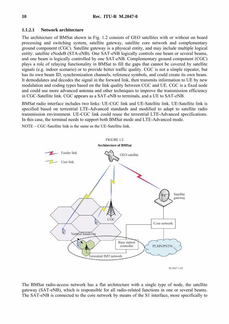
1.1.2.1 Network architecture
The architecture of BMSat shown in Fig. 1.2 consists of GEO satellites with or without on board processing and switching system, satellite gateway, satellite core network and complementary ground component (CGC). Satellite gateway is a physical entity, and may include multiple logical entity: satellite eNodeB (STA-eNB). One SAT-eNB logically controls one beam or several beams, and one beam is logically controlled by one SAT-eNB. Complementary ground component (CGC) plays a role of relaying functionality in BMSat to fill the gaps that cannot be covered by satellite signals (e.g. indoor scenario) or to provide better traffic quality. CGC is not a simple repeater, but has its own beam ID, synchronization channels, reference symbols, and could create its own beam. It demodulates and decodes the signal in the forward link, then transmits information to UE by new modulation and coding types based on the link quality between CGC and UE. CGC is a fixed node and could use more advanced antenna and other techniques to improve the transmission efficiency in CGC-Satellite link. CGC appears as a SAT-eNB to terminals, and a UE to SAT-eNB.
BMSat radio interface includes two links: UE-CGC link and UE-Satellite link. UE-Satellite link is specified based on terrestrial LTE-Advanced standards and modified to adapt to satellite radio transmission environment. UE-CGC link could reuse the terrestrial LTE-Advanced specifications. In this case, the terminal needs to support both BMSat mode and LTE-Advanced mode.
NOTE – CGC-Satellite link is the same as the UE-Satellite link.
FIGURE 1.2
Architecture of BMSat
M.2047-1-02
Feeder link
User link
GEO satellite
Satellitegateway
CGC
Vertical handover
Terrestrial IMT network
Core network
Base stationcontroller PLMN/PSTN/...
The BMSat radio-access network has a flat architecture with a single type of node, the satellite gateway (SAT-eNB), which is responsible for all radio-related functions in one or several beams. The SAT-eNB is connected to the core network by means of the S1 interface, more specifically to

Rec. ITU-R M.2047-0 11
the serving gateway (S-GW) by means of the user-plane part, S1-u, and to the Mobility Management Entity (MME) by means of the control-plane part, S1-c. One SAT-eNB can interface to multiple MMEs/S-GWs for the purpose of load sharing and redundancy.
The X2 interface, connecting SAT-eNBs to each other, is mainly used to support active-mode mobility. This interface may also be used for multi-beam Radio Resource Management (RRM) functions such as IBIC. The X2 interface is also used to support lossless mobility between neighbouring beams by means of packet forwarding.
FIGURE 1.3
Radio-access network interfaces of BMSat
M.2047-1-03
Satellite gateway
Satellite gatewaySatellite gateway
S-GW S-GW
MME
MME
Core network
S1-c
S1-u
S1-u
S1-c
S1 -
u S1-c
S1-u
S1-c
X2
X2X2
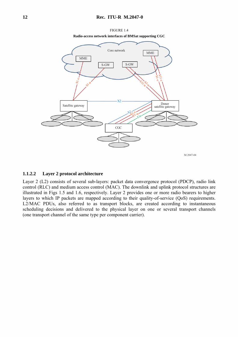
The radio-access network interfaces for BMSat supporting CGCs are shown in Fig.1.4. The CGC terminates the S1, X2 and Un interfaces. The Donor SAT-eNB (DSAT-eNB) provides S1 and X2 proxy functionality between the CGC and other network nodes (other SAT-eNBs, MMEs and S-GWs). The S1 and X2 proxy functionality includes passing UE-dedicated S1 and X2 signalling messages as well as GTP data packets between the S1 and X2 interfaces associated with the CGC and the S1 and X2 interfaces associated with other network nodes. Due to the proxy functionality, the DSAT-eNB appears as an MME (for S1-c), an SAT-eNB (for X2) and an S-GW (for S1-u) to the CGC.
12 Rec. ITU-R M.2047-0
FIGURE 1.4
Radio-access network interfaces of BMSat supporting CGC
M.2047-04
Core network
MME
S-GW S-GW
MME
Satellite gateway Donorsatellite gateway
CGC
S1-uS1
-cS1-u
S11-u
S11-c
S1-c
X2
X2S1-c
S1-uUn
1.1.2.2 Layer 2 protocol architecture
Layer 2 (L2) consists of several sub-layers: packet data convergence protocol (PDCP), radio link control (RLC) and medium access control (MAC). The downlink and uplink protocol structures are illustrated in Figs 1.5 and 1.6, respectively. Layer 2 provides one or more radio bearers to higher layers to which IP packets are mapped according to their quality-of-service (QoS) requirements. L2/MAC PDUs, also referred to as transport blocks, are created according to instantaneous scheduling decisions and delivered to the physical layer on one or several transport channels (one transport channel of the same type per component carrier).

Rec. ITU-R M.2047-0 13
FIGURE 1.5
Downlink L2 protocol structure
M.2047-05
ROHCROHC
Security Security
Segm.ARQ etc
Segm.ARQ etc
PDCP
RLC
ROHCROHC
Security Security
Segm.ARQ etc
Segm.ARQ etc
Radio bearers
Logical channels
CCCH BCCH PCCH
Segm. Segm.
MCCH MTCH
Unicast scheduling / Priority handling
MACMultiplexing UE 1 Multiplexing UE n
HARQ HARQ
DL-SCHon CC1
DL-SCHon CC
x
Transport channels
HARQ HARQ
DL-SCHon CC1
DL-SCHon CC
y
BCH PCH
Multiplexing
MCH
MBMS scheduling
FIGURE 1.6
Uplink L2 protocol structure
M.2047-06
ROHC ROHC
Security SecurityPDCP
RLCSegm.
ARQ etcSegm.
ARQ etc
Radio bearers
CCCH
Logical channels
Transport channels
Scheduling / Priority handling
Multiplexing
HARQ HARQ
UL-SCHon CC1
UL-SCHon CC
z
MAC
1.1.2.2.1 Packet data convergence protocol
Packet data convergence protocol (PDCP) is responsible for:
– User plane:
– Header compression and decompression of IP data flows using ROHC.
– Transfer of user data.
– Maintenance of PDCP Sequence Numbers (SNs).
– In-sequence delivery of upper layer PDUs at PDCP re-establishment procedure for RLC AM.

14 Rec. ITU-R M.2047-0
– Duplicate detection of lower layer SDUs at PDCP re-establishment procedure for RLC AM.
– Retransmission of PDCP SDUs at handover for RLC AM.
– Ciphering and deciphering.
– Timer-based SDU discard in uplink.
– Control plane:
– Maintenance of PDCP Sequence Numbers (SNs).
– Ciphering and Integrity Protection and Verification.
– Transfer of control plane data.
PDCP uses the services provided by the RLC sub-layer. There is one PDCP entity per radio bearer configured for a UE.
1.1.2.2.2 Radio link control
Radio link control (RLC) is responsible for:
– Transfer of upper layer PDUs.
– Error correction through automatic repeat request (ARQ) (only for AM data transfer).
– Concatenation, segmentation and reassembly of RLC SDUs (only for UM and AM data transfer).
– Resegmentation of RLC data PDUs (only for AM data transfer).
– Reordering of RLC data PDUs (only for UM and AM data transfer).
– Duplicate detection (only for UM and AM data transfer).
– Protocol error detection (only for AM data transfer).
– RLC SDU discard (only for UM and AM data transfer).
– RLC re-establishment.
Depending on the mode of operation, an RLC entity may provide all, a subset of, or none of the services above. The RLC can operate in three different modes:
– Transparent mode I, where the RLC is completely transparent and is in essence bypassed. This configuration is used for control-plane broadcast channels such as broadcast control channel (BCCH), common control channel (CCCH) and paging control channel (PCCH) only where the information should reach multiple users.
– Unacknowledged mode (UM), where the RLC provides all the functionality above except error correction, is used when error-free delivery is not required, for example for multicast control channel (MCCH) and multicast traffic channel (MTCH) using multimedia broadcast over a single frequency network (MBSFN) and for voice-over-IP (VoIP).
– Acknowledged mode (AM), where the RLC provides all the services above, is the main mode of operation for TCP/IP packet data transmission on the downlink shared channel (DL-SCH). Segmentation/reassembly, in-sequence delivery and retransmissions of erroneous data are all supported.
The RLC offers services to the PDCP in the form of radio bearers and uses services from the MAC layer in the form of logical channels. There is one RLC entity per radio bearer configured for a terminal.

Rec. ITU-R M.2047-0 15
1.1.2.2.3 Medium access control
The Medium access control (MAC) layer is responsible for:
– Mapping between logical channels and transport channels.
– Multiplexing/demultiplexing of MAC SDUs belonging to one or different logical channels into/from transport blocks delivered to/from the physical layer on transport channels.
– Scheduling information reporting.
– UE-CGC link: Error correction through N-process stop-and-wait hybrid-ARQ (HARQ) with synchronous (for the uplink) and asynchronous (for the downlink) retransmissions.
– UE-Satellite link: Error correction through virtual hybrid-ARQ (V-HARQ) with synchronous (for the uplink) and asynchronous (for the downlink) retransmissions.
– Priority handling between logical channels of one UE.
– Priority handling between UEs by means of dynamic scheduling.
– Logical channel prioritization.
– Multimedia broadcast/Multicast service (MBMS) identification.
– Transport format selection.
– Padding.
The MAC offers services to the RLC in the form of logical channels. A logical channel is defined by the type of information it carries and is generally classified as a control channel, used for transmission of control and configuration information necessary for operating a BMSat system, or as a traffic channel, used for the user data. The set of logical-channel types specified for BMSat includes:
– Broadcast control channel (BCCH), used for broadcasting system control information.
– Paging control channel (PCCH), a downlink channel used for paging when the network is not aware of the location of the UE and for system information change notifications.
– Common control channel (CCCH), used for transmission of control information between UEs and network when the UE has no RRC connection.
– Dedicated control channel (DCCH), used for transmission of control information to/from a mobile terminal when the UE has a RRC connection.
– Multicast control channel (MCCH), used for transmission of control information required for reception of the MTCH.
– Dedicated traffic channel (DTCH), used for transmission of user data to/from a mobile terminal. This is the logical channel type used for transmission of all uplink and non-MBSFN downlink user data.
– Multicast traffic channel (MTCH), used for downlink transmission of MBMS services.
From the physical layer, the MAC layer uses services in the form of transport channels. A transport channel is defined by how and with what characteristics the information is transmitted over the radio interface. Data on a transport channel is organized into transport blocks. In each transmission time interval (TTI), at most one or two (in case of spatial multiplexing) transport blocks are transmitted per component carrier.
Associated with each transport block is a transport format (TF), specifying how the transport block is to be transmitted over the radio interface. The transport format includes information about the transport-block size, the modulation scheme, and the antenna mapping. The scheduler is responsible for (dynamically) determining the uplink as well as downlink transport format in each TTI.

16 Rec. ITU-R M.2047-0
The following transport-channel types are defined:
– Broadcast channel (BCH) has a fixed transport format, provided by the specifications. It is used for transmission of parts of the BCCH system information, more specifically the so-called master information block (MIB).
– Paging channel (PCH) is used for transmission of paging information from the PCCH logical channel. The PCH supports discontinuous reception (DRX) to allow the mobile terminal to save battery power by waking up to receive the PCH only at predefined time instants.
– Downlink shared channel (DL-SCH) is the main transport-channel type used for transmission of downlink data in BMSat. It supports dynamic rate adaptation and channel-dependent scheduling, HARQ/V-HARQ with soft combining, and spatial multiplexing. It also supports DRX to reduce mobile-terminal power consumption while still providing an always-on experience. The DL-SCH is also used for transmission of the parts of the BCCH system information not mapped to the BCH. In case of transmission to a terminal using multiple component carriers the UE receives one DL-SCH per component carrier.
– Multicast channel (MCH) is used to support MBMS. It is characterized by a semi-static transport format and semi-persistent scheduling. In case of multi-beam transmission using MBSFN, the scheduling and transport format configuration is coordinated among the beams involved in the MBSFN transmission.
– Uplink shared channel (UL-SCH) is the uplink counterpart to the DL-SCH, i.e. it is the uplink transport channel used for transmission of uplink data.
In addition, the random access channel (RACH) is also defined as an uplink transport channel although it does not carry transport blocks. The RACH is used in the uplink to respond to the paging message or to initiate the move to the RRC_CONNECTED state according to terminal data transmission needs.
The mapping between logical channels, transport channels and physical channels (described in § 1.1.3.3) is illustrated in Fig. 1.7 for the downlink and Fig. 1.8 for the uplink.
FIGURE 1.7
Downlink channel mapping
M.2047-07
BCCH CCCH DTCH DCCH MTCH MCCHPCCH
BCH DL-SCH MCHPCH
PBCH PDSCH PDCCH PHICH PCFICHE-PPCH PMCH
Logicalchannels
Transportchannels
Physicalchannels
DCI

Rec. ITU-R M.2047-0 17
FIGURE 1.8
Uplink channel mapping
M.2047-08
CCCH DTCH DCCHLogicalchannels
Transportchannels
Physicalchannels
UL-SCH RACH
UCI
PUSCH PUCCH PRACH
1.1.2.3 Physical layer
For UE-CGC link, the physical layer is responsible for:
– Modulation and demodulation of physical channels.
– Error detection on the transport channel and indication to higher layers.
– Forward error correction (FEC) encoding and decoding of transport channels.
– Rate matching of the coded transport channel to physical channels.
– Mapping of the coded transport channel onto physical channels according to Fig. 1.7 (downlink) and Fig. 1.8 (uplink).
– Hybrid ARQ (HARQ) soft-combining.
– Frequency and time synchronization.
– Power weighting of physical channels.
– Multi-antenna processing and beamforming.
– Characteristic measurements and indication to higher layers.
– RF processing.
– A simplified overview of the processing for the DL-SCH is given in Fig. 1.9.

18 Rec. ITU-R M.2047-0
FIGURE 1.9
Simplified physical-layer processing for DL-SCH on one component carrier
M.2047-1-09
1 or 2 transport blocks of dynamic size per TTI
Hybrid ARQ
MA
C s
ched
uler
MAC
PHY
A c
k/N
ak
Hyb
rid
AR
Q in
fo
Red
unda
ncy
vers
ion
CRC
Coding, rate matching
Data modulation
Antenna mapping
Resource mapping
Modulationscheme
Antennaassignment
Resourceassignment
eNodeB
Hybrid ARQ MAC
PHY
A c
k/N
ak
Hyb
rid
AR
Q in
fo
Red
unda
ncy
vers
ion
CRC check
Decoding
Data demodulation
Antenna demapping
Resource demapping
Mobile terminal
Err
orin
dica
tion
For UE-Satellite link, three items of the physical layer as below are different to UE-CGC link:
– Virtual hybrid ARQ combining.
– A simplified overview of the processing for the DL-SCH is given in Fig. 1.10.
– Multi-antenna processing (beamforming is not supported).
FIGURE 1.10
Simplified physical-layer processing for DL-SCH on one component carrier with virtual HARQ
M.2047-1-10
1 or 2 transport blocks of dynamic size per TTI
MAC
PHY
CRC
Coding, Rate matching
Data modulation
Antenna mapping
Resource mapping
V-HARQ info
Modulationscheme
Antennaassignment
Resourceassignment
MA
C s
ched
uler
Satellite gateway
MAC
PHY
CRC check
Decoding
Data demodulation
Antenna demapping
Resource demapping
V-H
ARQ
info
Mobile terminal
V-HARQ
1.1.2.3.1 Physical channels
Seven different types of physical channels are defined for the downlink:
– Physical downlink shared channel (PDSCH): Used for transmission of user and control plane data services.

Rec. ITU-R M.2047-0 19
– Physical multicast channel (PMCH): Used for transmission of control and user-plane broadcast services during MBSFN subframes.
– Physical downlink control channel (PDCCH): Used for transmission of control information such as resource allocation, transport format and HARQ/V-HARQ related information.
– Physical broadcast channel (PBCH): Used for conveying beam and/or system specific information.
– Physical control format indicator channel (PCFICH): It indicates to the UE the control format (number of symbols comprising PDCCH, PHICH) of the current subframe.
– Physical hybrid ARQ indicator channel (PHICH): It conveys the ACK/NAK information for UL (PUSCH) transmissions received at CGC for UE-CGC link.
– Enhanced physical paging channel (E-PPCH): It conveys the enhanced paging information to page users in deep fading environment.
Three different types of physical channels are defined for the uplink:
– Physical random access channel (PRACH): It conveys a preamble which is used to trigger a random-access procedure in the SAT-eNB.
– Physical uplink shared channel (PUSCH): It conveys both user data and upper layer control information.
– Physical uplink control channel (PUCCH): It conveys control information (scheduling requests, CQI, PMI, RI, and HARQ/V-HARQ information for PDSCH, etc.).
1.1.2.3.2 Time-domain structure and duplex schemes
Figure 1.11 illustrates the high-level time-domain structure for transmission, with each (radio) frame of length 10 ms consisting of ten equally sized subframes of length 1 ms. Each subframe consists of two equally sized slots of length Tslot = 0.5 ms with each slot consisting of a number of OFDM symbols including cyclic prefix.
FIGURE 1.11
BMSat time-domain structure
M.2047-1-11
One frame, = 10 msTframe
One subframe, = 1 msTsubframe
One slot, = 0.5 msTslot
TCP
T T TCP s s: 160 • 5.1 s (first OFDM symbol), 144 4.7 s (remaining OFDM symbols)≈ μ ≈ μ
Normal CP
Extended CP
T Tu s 66.7 s (2 048 • )≈ μ
T Tu s 66.7 s (2 048 • )≈ μTCP – e
T TCP – e s: 512 • 16.7 s≈ μ
#0 #1 #2 #3 #4 #5 #6 #7 #8 #9
BMSat can operate in FDD as illustrated in Fig. 1.12.

20 Rec. ITU-R M.2047-0
FIGURE 1.12
Uplink/downlink time/frequency structure in case of FDD
M.2047-1-12
One radio frame, = 10 msTframe
One subframe, = 1 msTsubframe
UL
DLFDD
Subframe 0# #1 #2 #3 #4 #5 #6 #7 #8 #9
ƒULƒDL
There are two carrier frequencies for each component carrier, one for uplink transmission (fUL) and one for downlink transmission (fDL). During each frame, there are thus ten uplink subframes and ten downlink subframes and uplink and downlink transmission can occur simultaneously within a beam. Half-duplex operation at the UE side is supported by the scheduler ensuring non-simultaneous reception and transmission at the UE.
1.1.2.3.3 Physical layer processing
To the transport block(s) to be transmitted on a DL-SCH or UL-SCH, a CRC is attached, followed by rate-1/3 Turbo coding for error correction. Rate matching is used not only to match the number of coded bits to the amount of resources allocated for the DL-SCH/UL-SCH transmission, but also to generate the different redundancy versions as controlled by the HARQ/V-HARQ protocol. In case of spatial multiplexing, the processing is duplicated for the two transport blocks. After rate matching, the coded bits are modulated (QPSK, 16QAM, 64QAM for UE-CGC link; QPSK, 16QAM/16APSK for UE-Satellite link). In case of multi-antenna transmission, the modulation symbols are mapped to multiple layers and precoded before being mapped to the different antenna ports. Alternatively, transmit diversity can be applied. Finally, the (precoded) modulation symbols are mapped to the time-frequency resources allocated for the transmission.
Downlink transmission is based on conventional OFDM with a cyclic prefix. The subcarrier spacing is Δf = 15 kHz and two cyclic prefix lengths are supported: normal cyclic prefix ≈4.7 µs and extended cyclic prefix ≈16.7 µs. In the frequency domain, the number of resource blocks can range from 6 to 110 per component carrier (for channel bandwidths ranging from 1.4 to 20 MHz respectively), where a resource block is 180 kHz in the frequency domain. There can be up to five component carriers transmitted in parallel implying an overall bandwidth up to 100 MHz.
Uplink transmission is based on DFT-spread OFDM (DFTS-OFDM). DFTS-OFDM can be seen as a DFT precoder, followed by conventional OFDM with the same numerology as in the downlink. Multiple DFT precoding sizes, corresponding to transmission with different scheduled bandwidths, can be used.
Depending on the deployed satellite/UE power amplifier performance, DFTS-OFDM and Offset-modulated Single-Carrier (OSC) could be used in both uplink and downlink of UE-Satellite link.
The remaining downlink transport channels (PCH, BCH, MCH) are based on the same general physical-layer processing as DL-SCH, although with some restrictions in the set of features used.
1.1.2.3.4 Multi-antenna transmission
A wide range of multi-antenna transmission schemes are supported in the downlink of UE-CGC link:
– Single-antenna transmission using a single cell-specific reference signal.
Rec. ITU-R M.2047-0 21
– Closed-loop spatial multiplexing, also known as codebook-based beam-forming or precoding, of up to four layers using cell-specific reference signals. Feedback reports from the terminal are used to assist CGC in selecting a suitable precoding matrix.
– Open-loop spatial multiplexing, also known as large-delay cyclic delay diversity, of up to four layers using cell-specific reference signals.
– Spatial multiplexing of up to eight layers using UE-specific reference signals. CGC may use feedback reports or exploit channel reciprocity to set the beam-forming weights.
– Transmit diversity based on space-frequency block coding (SFBC) or a combination of SFBC and frequency switched transmit diversity (FSTD).
– Multi-user MIMO where multiple terminals are assigned overlapping time-frequency resources.
For downlink of UE-Satellite link:
– Transmit diversity based on SFBC (space-frequency block coding) with maximum 2 antenna ports is supported.
– Open-loop spatial multiplexing of up to two layers using cell-specific reference signals is supported.
The following multi-antenna transmission schemes are supported in the uplink of UE-CGC link:
– Single-antenna transmission.
– Precoding supporting rank-adaptive spatial multiplexing with one up to four layers.
For uplink of UE-Satellite link:
– Open-loop spatial multiplexing with up to 2 layers is supported.
– Open-loop and UE autonomous antenna selection diversity is supported.
1.1.2.3.5 Link adaptation and power control
According to the radio channel conditions, the modulation and coding scheme (MCS) can be adapted flexibly. The same modulation and coding is applied to all resource units assigned to the same transport block within a TTI. Uplink power control determines the average power over a DFTS-OFDM symbol in which the physical channel is transmitted.
1.1.2.3.6 L1/L2 control signalling
Downlink control information (DCI) is transmitted in the first one to three OFDM symbols of each downlink subframe in each component carrier with the number of OFDM symbols being indicated on the PCFICH. Downlink and uplink scheduling grants (consisting of UE identity, time-frequency resources and transport format) and virtual hybrid-ARQ information are transmitted on the PDCCH and PHICH, respectively. Each grant is transmitted on a separate PDCCH using QPSK modulation.
Uplink control information (UCI), consisting of channel-status information, scheduling requests and HARQ/V-HARQ information, is transmitted at the band edges of the primary uplink component carrier. Alternatively, parts of the control signaling can be multiplexed with data on PUSCH.
1.1.2.3.7 Multicast/Broadcast over single frequency network operation
Multicast/Broadcast over single frequency network (MBSFN) transmission, where the same signal is transmitted from multiple, time-synchronized beams, is supported by the MCH transport channel. One component carrier can support simultaneous unicast and broadcast support through time-domain multiplexing of MCH and DL-SCH transmissions.

22 Rec. ITU-R M.2047-0
1.1.3 Overview of the specific characteristics of the RIT
1.1.3.1 Low-EF transmission mode
Satellite communication system is typically power limited. In order to increase the power efficiency, two low envelope fluctuation (EF) transmission modes within the OFDM framework, DFT-spread OFDM used in terrestrial LTE uplink and offset-modulated single-carrier (OSC), could be used in both uplink and downlink.
1.1.3.1.1 OSC mode
The frequency domain transmission signal mapped to a set of subcarriers is generated by:
n
N
n
Nnmjm xe
N
m
Ny
−
=
+π−+π=1
0
/)5.0(2)5.0(sin
2
where:
{ } { }2 2 1Re and Im , 0,1, , / 2 1k k kkx x x x k N+ …= = −=
nx , 0,1, 1, / 2n N…= − ,
are complex-valued modulation symbols, N is the set size of sub-carriers.
FIGURE 1.13
Signal generation for OSC transmission mode
M.2047-1-13
Pre-processing
x0x1
Modulatedsymbol
00y0
y1
yN 1−
00
IDFTP/S ConvertCP insertionwindowing
Transmittedsignal
OSC: xN / 2 1−
1.1.3.2 Virtual Hybrid ARQ
The Hybrid ARQ (HARQ) scheme used in terrestrial LTE systems cannot work effectively because of long radio transmission delay in satellite communication systems. However, by utilizing the terrestrial LTE HARQ process, a new scheme, virtual HARQ without ACK/NACK feedback, is designed to support a wider range of channel conditions as well as transmission rates.
In order to support effective transmission in low SINR region, low rate MCS levels should be supported. The MCS levels can be equivalently extended by using the LTE HARQ process. In virtual HARQ scheme, based on the reported CQI from the receiver, the transmitter adaptively selects both the MCS level and the number of transmitted redundancy versions. This scheme can support data transmission in very low SINR channel condition by selecting maximum 4 redundancy versions.
A Transmit processing for virtual HARQ
Based on the feedback CQI, the transmitter selects at the same time both the MCS level and the number of simultaneously transmitted redundancy versions for a given number of TTI, typically a single TTI. By this way the transmission rate has a more flexible choice in contrast to AMC in LTE.

Rec. ITU-R M.2047-0 23
Each MCS corresponds to an efficient code rate (ECR) in LTE, and 29 ECRs are supported in LTE. For 64QAM is not supported in BMSat, the number of other remaining MCS/ECR is 17. When the selections of MCS and the number of simultaneously transmitted redundancy versions are combined, the 17 ECRs will be extended to 68 ECRs in BMSat. Among all possible ECRs or its subset, the maximum transmission rate that is less than the channel capacity will be selected.
Once the transmission rate, i.e. the MCS level and the number of simultaneously transmitted redundancy versions, is determined, the transmitter calculates the data size to match the determined rate. After rate matching, each redundancy version goes through symbols modulation, concatenation, resource mapping and OFDM modulation. If multiple redundancy versions are selected to be transmitted in one TTI, they will be concatenated in time or space dimension.
B Virtual HARQ receiver
The receiver first de-concatenates the received signal corresponding to multiple redundancy versions in one TTI if needed. Then, the HARQ decoding method in LTE is used in BMSat by viewing multiple redundancy versions simultaneously transmitted in one TTI as retransmitted ones.
FIGURE 1.14
Virtual hybrid ARQ
M.2047-1-14
Mode 1:(1 redundancy
version)
#
Mode 2:(2 redundancy
versions)
#
Mode 4:(4 redundancy
versions)
#
Link adaption
V.0 V.0 V.0
V.0 V.0 V.0 V.1 V.1 V.1
V.0 V.0 V.0 V.1 V.1 V.1 V.2 V.2 V.2 V.3 V.3 V.3
PDU 1 in HARQprocess 1 (RV x)
# PDU 2 in HARQprocess 2 (RV x)
# PDU 3 in HARQprocess 3 (RV x)
#
Time
V.x V.x V.x
1.1.3.3 Long TTI bundling
Due to the large path loss of satellite link and UE/satellite transmission power limitation, UL/DL transmission may be power limited for some classes of UE. In order to improve coverage of PDSCH/PUSCH transmission, a long period TTI bundling (up to 20 ms) approach can be configured. By TTI bundling, one transport block will be transmitted in multiple successive subframes. The total transmission power of the packet is boosted. Transmission of a transport block in case of long TTI bundling is defined in terms of the following steps (Fig. 1.15):
– encoding of source bits in each of the codewords to be transmitted;
– scrambling of coded bits in each of the codewords to be transmitted;
– modulation of scrambled bits to generate complex-valued modulation symbols;
– mapping of the complex-valued modulation symbols of the transport block on an antenna
port into each TTI bundling subframe: ( ) ( )= × +q SFsymx n d q M n , 0,1,..., 1= −q Q , 0,1,..., 1= −SF
symn M ,

24 Rec. ITU-R M.2047-0
where Q is the number of bundled subframes, SFsymM is the number of modulation symbols
that mapped into each subframe, ( )qx n is the nth modulation symbol mapped into the qth
subframe, ( )⋅d is the complex-valued modulation symbols of the transport block;
– generating time-domain signal to be transmitted in each subframe.
To improve spectrum efficiency, code-division multiple access on top of OFDMA (SC-FDMA) can be used when generating time-domain signal in each subframe. To be specific, the procedure includes the following steps:
– spreading of the complex-valued modulation symbols in each subframe, an example can be
found in Fig. 1.16, the nth modulation symbol of subframe q is spread by 0 1 1, ,..., − SFNw w w,
where NSF is the length of spreading code;
– mapping of the spread symbols to resource elements, for example in Fig. 1.16, the spread symbols of the nth modulation symbols are mapped to the nth subcarrier of all SC-FDMA symbols except the symbols for reference signal;
– generating time-domain signal for each subframe.
FIGURE 1.15
Long TTI bundling transmission
M.2047-1-15
Source bits Channelcoding Scrambling Modulation Subframe
mapping
Subframes
Subframe signalgeneration
Subframe signalgeneration
FIGURE 1.16
Mapping of spread symbols to resource elements (UL) (Example)
M.2047-1-16
Reference signal Data
OFDM symbol
Sub
carr
iers
xq (12)
[ ]w , w ,...w0 1 N –SF 1
xq (0)
[ ]w , w ,...w0 1 N –SF 1
1.1.3.4 Random access optimization
The propagation delay of satellite system is much longer than terrestrial LTE system. The terrestrial LTE access procedure needs to be optimized to adapt the long delay.
Depending on whether UE can obtain time advance (TA) in advance, two access schemes can be used in BMSat:

Rec. ITU-R M.2047-0 25
– RACH-less Access: for UE can obtain the accurate TA in advance;
– RACH: for UE cannot obtain TA in advance.
1.1.3.4.1 RACH-less access
In case the UE can obtain the accurate TA value in advance, the random access procedure can be avoided and the RACH-less access procedure can be used. The RACH-less access procedure is performed for the following three example cases:
1) The UE has accessed the satellite and obtained the TA value before. And the TA value stored by UE in still valid for the time span between the last access and current access is short.
2) The UE deduces the TA value between itself and the satellite through the implementation method, e.g. the UE can obtain the distance between itself and the satellite using the global navigation satellite system (GNSS).
3) A satellite broadcasts a reference time in UTC, a UE equipped with GNSS can deduce the TA value according to the time difference between the time it receives the broadcast message and the reference time value from the satellite.
In the RACH-less access procedure, the satellite gateway broadcasts a set of contention-based PRBs, the access UE chooses one contention-based PRB to send data with its identifier. If the data transmission is successful, the satellite gateway should send UE a response. Otherwise, an access collision may occur, UE may retry the access procedure after a random back-off time.
FIGURE 1.17
RACH-less access
M.2047-1-17
UE Satellite GW
1. Obtain TA
2. broadcast contention-based
resource
3. data transmission on contention-basedresource
4. ACK for data transmission
NOTE – If the calculated TA is larger than the cycle time T of contention-based PRBs, TA = TA mod T.

26 Rec. ITU-R M.2047-0
1.1.3.4.2 RACH optimization
In case UE cannot obtain the TA value in advance, the LTE RACH procedure can be reused. Two points of optimization can be adopted.
1) For the diameter of a satellite beam ranging from 100 to 500 km, the time difference of the satellite receiving the uplink synchronization codes from different UEs in the same beam may exceed the synchronization detection window. Therefore, the length of CP and GT needs to be adjusted according to the beam range (see § 1.1.3.7).
2) For the satellite having a number of beams, the transmission delay from the satellite to each beam is different. To ensure the RACH preambles from different beams to arrive the satellite in the detection window, the satellite broadcasts the propagation delay (i.e. T delay) from satellite to reference location of a beam (e.g. the centre of a beam) in each satellite beam. The UEs in the beam then set RACH preamble transmission time according to the T delay to make sure the preamble can be received by satellite in the detection window.
FIGURE 1.18
Broadcasting of the propagation delay from satellite to reference location of a beam (Example)
M.2047-1-18
Satellite
Tdelay2
Tdelay1
Tdelay3
1.1.3.5 Handover optimization
Compared with the terrestrial LTE system, the handover procedure in satellite communication system is more complex. Three handover scenarios are introduced: intra-satellite inter-beam handover, satellite to terrestrial handover and terrestrial to satellite handover. Some enhancements to optimize the handover procedure should be considered to reduce the handover interruption time caused by the long propagation delay.
Handover is based on UE assisted network control, i.e. the handover decision for a UE in connected mode is made by the network, based on possible measurement reports from the UE. The UE measurements are based on the reference symbol strength or quality, and various measurement reporting conditions are configurable by the network.
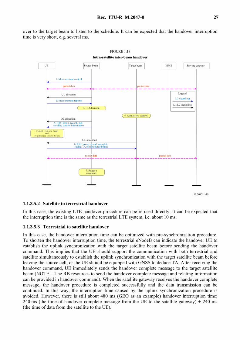
1.1.3.5.1 Intra-satellite inter-beam handover
Inter-beam tight synchronization usually can be achieved, and the uplink time advances of source beam and target beam are the same. Based on this tight synchronization, the handover UE can avoid performing the RACH procedure in the target beam to accelerate the handover procedure. After the handover command is sent from the source beam, the target beam can directly schedule the handover UE in the target beam. When UE receives the handover command, it immediately hands
Rec. ITU-R M.2047-0 27
over to the target beam to listen to the schedule. It can be expected that the handover interruption time is very short, e.g. several ms.
FIGURE 1.19
Intra-satellite inter-beam handover
M.2047-1-19
UE Source beam Target beam MME Serving gateway
UL allocation
3. HO decision
4. Admission controlDL allocation
Detach from old beamand
synchronize to new beam
UL allocation
7. Releaseresources
Legend
L1/L2 signalling
L3 signalling
1. Measurement control
2. Measurement reports
5. RRC Conn. reconf. incl.mobility control information
6. RRC conn. reconf. complete (using TA of the source beam)
packet data packet data
packet data packet data
1.1.3.5.2 Satellite to terrestrial handover
In this case, the existing LTE handover procedure can be re-used directly. It can be expected that the interruption time is the same as the terrestrial LTE system, i.e. about 10 ms.
1.1.3.5.3 Terrestrial to satellite handover
In this case, the handover interruption time can be optimized with pre-synchronization procedure. To shorten the handover interruption time, the terrestrial eNodeB can indicate the handover UE to establish the uplink synchronization with the target satellite beam before sending the handover command. This implies that the UE should support the communication with both terrestrial and satellite simultaneously to establish the uplink synchronization with the target satellite beam before leaving the source cell, or the UE should be equipped with GNSS to deduce TA. After receiving the handover command, UE immediately sends the handover complete message to the target satellite beam (NOTE – The RB resources to send the handover complete message and relating information can be provided in handover command). When the satellite gateway receives the handover complete message, the handover procedure is completed successfully and the data transmission can be continued. In this way, the interruption time caused by the uplink synchronization procedure is avoided. However, there is still about 480 ms (GEO as an example) handover interruption time: 240 ms (the time of handover complete message from the UE to the satellite gateway) + 240 ms (the time of data from the satellite to the UE).

28 Rec. ITU-R M.2047-0
1.1.3.6 Paging enhancement
The terminal of satellite mobile communication systems sometimes works in very low SNR regions such as indoor environments or strong shadowed environments. In these scenarios, the signal strength will be much lower than the SNR threshold of normal paging decoding, which means a coming call cannot reach the user.
This problem is solved by means of enhanced paging in BMSat. The enhanced paging can inform the users who are in strong shadowed environment, that a call is coming, and the user can choose to move outdoor or out of the shadowing to receive the call. For this purpose, the decoding threshold for enhanced paging should be much lower than that of the normal paging.
For enhanced paging, a new physical channel E-PPCH within the LTE frame structure is designed in BMSat.
1.1.3.6.1 Payload on E-PPCH
For normal paging in LTE, an S-TMSI (temporary mobile subscriber identity) is used for searching a user in the tracking area. The S-TMSI is composed of 8 bits MMEC (mobility management entity code) and 32 bits M-TMSI. MME is an entity for control message processing in the core networks of LTE. Several MMEs compose a MME pool, and the MMEC is used to uniquely identify a MME within an MME pool. The M-TMSI is a temporary identity for a subscriber in one MME.
Generally, one MME is enough for one satellite gateway, thus, M-TMSI is enough for normal paging and enhanced paging in BMSat, and MMEC is not necessary for BMSat.
1.1.3.6.2 Resource allocation for E-PPCH
Since E-PPCH is a new physical channel designed for enhanced paging, the mapping of the message to resource elements in BMSat should be arranged carefully to avoid superposition with control channels and synchronization channels.
Figure 1.20 shows the frequency-time resources in BMSat for slot 0/slot 10 and slot 1/ slot 11. The basic unit for resource allocation in BMSat is a PRB (physical resource block), which is composed of 12 subcarriers (180 kHz) during one slot (7 OFDM symbols). The first three OFDM symbols in each TTI (composed of two slots) are usually used for control information, and the 6th and 7th OFDM symbols of the central 6 PRBs (72 subcarriers) in slot 0 and slot 10 are used for SSS (secondary synchronization signal) and PSS (primary synchronization signal), respectively.
Based on the above considerations, the 4th and the 5th OFDM symbols of the central 6 PRBs in slot 0 and slot 10 are assigned as E-PPCH as shown in Fig. 1.20.
1.1.3.6.3 Reliable transmission of enhanced paging
To increase the SNR for enhanced paging decoding, two approaches are considered. The first is to apply “time spread” to decrease the decoding SNR threshold. By “time spread”, the short message is extended by dozens of times, so that spread gain can be obtained at the receiver by “time de-spread”. For further performance improvement, the time spread message can be repeated several times as required. The second approach is to increase the transmit power of the E-PPCH signal.

Rec. ITU-R M.2047-0 29
FIGURE 1.20
Resource allocation for E-PPCH
M.2047-1-20
Slot 0 / Slot 10 Slot 1 / Slot 11
E–PPCH
72 s
ubca
rrie
rs
Nc
SSS PSS
Control area Data area
1.1.3.6.4 Energy saving for un-targeted users
By time spread, the 32 bits M-TMSI may be extended by dozens of times. If the extended sequence is transmitted as a whole, the recovery of the M-TMSI message at the receiver will take a long time. In this case, the un-targeted users will waste a lot of energy before knowing that the M-TMSI in the message does not match their own M-TMSI.
To solve this problem, the 32 bits M-TMSI is divided into S segments with 32/S bits in each segment. All users will decode the message segment by segment, and do the comparison of the current decoded segment to the corresponding part of their own M-TMSI.
The decoding of the following segments of the message will go on only when the previous received segments all match the local M-TMSI. In this way, the un-targeted users can stop the detection as soon as possible, so that much of the energy is saved.
1.1.3.6.5 Procedure for the enhanced paging
The whole procedure is shown in Fig. 1.21. At the transmitter, the 32 bits M-TMSI message is firstly divided into several segments. Each segment is then attached a segment ID, which is used for the segment comparison at the receiver. Each M-TMSI segment with ID is then mapped to a Zadoff-Chu sequence, which is actually the time spread process. Since the Zadoff-Chu sequence for each M-TMSI segment is usually longer than 72, it should be divided into several segments firstly,

30 Rec. ITU-R M.2047-0
and then mapped to the allocated resource blocks. After OFDM modulation, the whole message is repeated as required.
At the receiver, the repeated message is firstly combined for current M-TMSI segment. After OFDM demodulation and resource blocks extraction, the segments of sequence for current M-TMSI are concatenated. The ML method can then be used for sequence detection, and the current M-TMSI segment with its segment ID is recovered according to the sequence mapping rules. With the help of the segment ID, the receiver compares the received M-TMSI segment with the corresponding part of the local M-TMSI. If current M-TMSI segment matches, the receiver will continue to detect the next M-TMSI segment. Otherwise, the receiver will stop for the E-PPCH detection. When the whole received M-TMSI matches the local M-TMSI, the receiver can inform the user that an E-PPCH is received.
E-PPCH configurations are broadcasted in system information blocks.
FIGURE 1.21
A complete design for enhanced paging
M.2047-1-21
TMSI TMSIsegmen-
tation
001+010+
...111+
ZCSequencemapping
Sequencesegmenta-
tion
Mappingto RBs
OFDMmodul-ation
P/S &repeat
Channel
Combin-ation
OFDMde-
modul-ation
RB sextrac-
tion
Sequenceconcaten-
ation
Sequencedetection
Segmentrecovery &comparison
E-PCHconfirm-
ation
YesYes
No
Last? Match?No
Stop
Continue for the next TMSI segment
1.1.3.7 Specific modification for long delay
1.1.3.7.1 PRACH configuration
In the terrestrial LTE system, several PRACH configurations are defined to support a maximum of 100 km coverage range. Satellite beam coverage targets to support much wider area with diameter from 100 km to 500 km. One PRACH configuration “sat1” is added in BMSat in Table 1.1.

Rec. ITU-R M.2047-0 31
TABLE 1.1
PRACH configuration
Preamble format
TCP TSEQ Sequence Length
GT
0 3168Ts 24576Ts 839 ≈97.4 us
1 21024Ts 24576Ts 839 ≈516 us
2 6240Ts 2*24576Ts 839 ≈197.4 us
3 21024Ts 2*24576Ts 839 ≈716 us
4 (frame
structure type 2 only)
448Ts 4096Ts 139 ≈9.4 us
Sat1 41024Ts 2*24576Ts 839 ≈1280 us
1.1.3.7.2 Period CQI feedback configuration
The maximal CQI feedback period of terrestrial LTE system is 160 ms. It is extended to support a maximum of 2 048 ms in BMSat.
TABLE 1.2
CQI feedback configuration
/CQI PMII Value of pdN Value of ,OFFSET CQIN
0 ≤ /CQI PMII ≤ 1 2 /CQI PMII
2 ≤ /CQI PMII ≤ 6 5 /CQI PMII
– 2
7 ≤ /CQI PMII ≤ 16 10 /CQI PMII
– 7
17 ≤ /CQI PMII ≤ 36 20 /CQI PMII
– 17
37 ≤ /CQI PMII ≤ 76 40 /CQI PMII
– 37
77 ≤ /CQI PMII ≤ 156 80 /CQI PMII
– 77
157 ≤ /CQI PMII ≤ 316 160 /CQI PMII
– 157
/CQI PMII = 317 Reserved
318 ≤ /CQI PMII ≤ 349 32 /CQI PMII
– 318
350 ≤ /CQI PMII ≤ 413 64 /CQI PMII
– 350
414 ≤ /CQI PMII ≤ 541 128 /CQI PMII
– 414
542 ≤ /CQI PMII ≤ 641* 256 /CQI PMII
– 542
642 ≤ /CQI PMII ≤ 741* 512 /CQI PMII
– 642

32 Rec. ITU-R M.2047-0
TABLE 1.2 (end)
/CQI PMII Value of pdN Value of ,OFFSET CQIN
742 ≤ /CQI PMII ≤ 841* 1024 /CQI PMII
– 742
842 ≤ /CQI PMII ≤ 941* 2048 /CQI PMII
– 842
942 ≤ /CQI PMII ≤ 1023 Reserved
1.1.3.7.3 QCI table
There are 9 standardized classes of QCI level pre-defined in LTE system to support a wide range of services. The services with very short delay like real-time gaming cannot be supported by satellite communication. Therefore, the original LTE QCI 3 is deleted in BMSat and other eight standardized QCI classes are left in BMSat. In addition, the packet delay budget is optimized to support satellite long delay.
TABLE 1.3
QCI configuration
QCI Resource
type Priority
Packet delay
budget
Packet error loss
rate Example services
1 GBR 2 100 ms + x 10−2 Conversational voice
2 3 150 ms + x 10−3 Conversational video (live streaming)
3 4 300 ms + 2x 10⁻⁶ Non-conversational video (buffered streaming)
4 Non-GBR 1 100 ms + 2x 10⁻⁶ IMS signalling
5 5 300 ms + 2x 10⁻⁶ Video (buffered streaming) TCP-based (e.g. www, e-mail, chat, ftp, p2p file sharing, progressive video, etc.)
6 6 100 ms + 2x 10⁻³ Voice, Video (live streaming) Interactive gaming
7 7 300 ms + 2x 10⁻⁶ Video (buffered streaming) TCP-based (e.g. www, e-mail, chat, ftp, p2p file)
8 8 sharing, progressive video, etc.
NOTE – x is the average transmission delay between UE and satellite gateway.
“+x”, service is assumed to be transmitted with RLC UM;
“+2x”, service is assumed to be transmitted with RLC AM.
1.1.3.8 Network coding
In mobile-satellite communication systems, a simple XOR-based network coding technology is used to improve the downlink frequency efficiency.

Rec. ITU-R M.2047-0 33
First, the connected two users transmit messages in different uplink channels. Second, the ground station (or the on-board processor) decodes the messages from two uplink channels, and transmits the XOR of the two decoded messages in the same downlink channel. Third, the two users decode the XOR message and recover the message from the other user by XOR the received message with the uplink message of itself. The mobile satellite communication system is power limited, especially for downlink transmission, so using one downlink channel to serve two users, the system capacity improves significantly.
1.2 Detailed specification of the radio interface technology
The detailed specifications of IMT-Advanced satellite radio interface technology entitled BMSat were uploaded in the web site of China Communications Standards Association (CCSA).
The BMSat specifications are based upon the LTE-Advanced specifications, and their relationship is defined in Table 1.4.
TABLE 1.4
Relationship between BMSat specifications and LTE-Advanced specifications
Terminology Definition
LTE-Advanced applies The feature of this BMSat specification is identical to that of LTE-Advanced, and hence the associated LTE-Advanced specification applies.
BMSat specific This BMSat specification describes a new BMSat feature that has no equivalent feature in LTE-Advanced.
Replaces LTE-Advanced The BMSat specification is a replacement for the associated LTE-Advanced specification. The BMSat specification may make reference to the associated LTE-Advanced specification.
The BMSat family of specifications are organized in document series that correspond to the LTE-Advanced document structure as shown in Table 1.5.
TABLE 1.5
Structure of the BMSat family of specifications
BMSat LTE-Advanced
BMSat Specific TS 36.0xx.2 series
Radio Layer 1 TS 36.2xx.0/2 series TS 36.2xx series
Radio Layers 2&3 TS 36.3xx.0/2 series TS 36.3xx series
Architecture TS 36.4xx.0/2 series TS 36.4xx series
where:
− TS xx.yyy.0 is used for BMSat specifications that have a corresponding LTE-Advanced specification. In this case, the numbers xx and yyy correspond to the LTE-Advanced numbering scheme.
− TS xx.yyy.2 is used for BMSat specifications that do not correspond to an LTE-Advanced specification. In this case, only the number xx corresponds to the LTE-Advanced numbering scheme and the number yyy is allocated by BMSat.

34 Rec. ITU-R M.2047-0
The complete contents of the BMSat family of specifications are given in TS BMSat 36.001.2. This section only briefly introduces the specifications that define the differences (i.e. the modifications) relative to the terrestrial LTE-Advanced specifications, i.e. the specifications that are “BMSat specific” and “Replaces LTE-Advanced”.
1.2.1 BMSat Specific
1.2.1.1 TS BMSat 36.001.2
Introduction to the BMSat family
This document gives a general introduction to the specifications in the BMSat family.
Location: http://www.ccsa.org.cn/english/files.php?docpath=/ITU-R/BMSat.
1.2.1.2 TS BMSat 36.002.2
BMSat; General Description
This document is a general description to the BMSat system and the associated air interface specification. It is intended to point out some of the differences between the terrestrial LTE-Advanced system and the mobile satellite BMSat system.
Location: http://www.ccsa.org.cn/english/files.php?docpath=/ITU-R/BMSat.
1.2.2 Radio Layer 1
1.2.2.1 TS BMSat 36.201.0
Evolved Universal Satellite Radio Access (E-USRA); BMSat physical layer; General description
This document provides a general description of the physical layer of the E-USRA radio interface. This document also describes the document structure of the E-USRA physical layer specifications, i.e. TS BMSat 36.200 series. The TS BMSat 36.200 series specifies the Uu point for the BMSat systems, and defines the minimum level of specifications required for basic connections in terms of mutual connectivity and compatibility.
Location: http://www.ccsa.org.cn/english/files.php?docpath=/ITU-R/BMSat.
1.2.2.2 TS BMSat 36.211.0
Evolved Universal Satellite Radio Access (E-USRA); Physical channels and modulation
This document describes the physical channels and modulation for E-USRA.
Location: http://www.ccsa.org.cn/english/files.php?docpath=/ITU-R/BMSat.
1.2.2.3 TS BMSat 36.212.0
Evolved Universal Satellite Radio Access (E-USRA); Multiplexing and channel coding
This document specifies the coding, multiplexing and mapping to physical channels for E-USRA.
Location: http://www.ccsa.org.cn/english/files.php?docpath=/ITU-R/BMSat.
1.2.2.4 TS BMSat 36.213.0
Evolved Universal Satellite Radio Access (E-USRA); Physical layer procedures
This document specifies and establishes the characteristics of the physical layer procedures for E-USRA.
Location: http://www.ccsa.org.cn/english/files.php?docpath=/ITU-R/BMSat.

Rec. ITU-R M.2047-0 35
1.2.2.5 TS BMSat 36.216.0
Evolved Universal Satellite Radio Access (E-USRA); Physical layer for CGC operation
This document describes the characteristics of the transmissions between SAT-eNB and CGC transmissions.
Location: http://www.ccsa.org.cn/english/files.php?docpath=/ITU-R/BMSat.
1.2.3 Radio Layers 2&3
1.2.3.1 TS BMSat 36.300.0
Evolved Universal Satellite Radio Access (E-USRA) and Evolved Universal Satellite Radio Access Network (E-USRAN); Overall description; Stage 2
This document provides an overview and overall description of the E-USRAN radio interface protocol architecture. Details of the radio interface protocols are specified in companion specifications of the 36 series.
Location: http://www.ccsa.org.cn/english/files.php?docpath=/ITU-R/BMSat.
1.2.3.2 TS BMSat 36.321.0
Evolved Universal Satellite Radio Access (E-USRA); Medium Access Control (MAC) protocol specification
This document specifies the E-USRA Medium Access Control (MAC) protocol.
Location: http://www.ccsa.org.cn/english/files.php?docpath=/ITU-R/BMSat.
1.2.3.3 TS BMSat 36.331.0
Evolved Universal Satellite Radio Access (E-USRA); Radio Resource Control (RRC); Protocol specification
This document specifies the Radio Resource Control protocol for the radio interface between UE and E-USRAN as well as for the radio interface between CGC and E-USRAN.
Location: http://www.ccsa.org.cn/english/files.php?docpath=/ITU-R/BMSat.
1.2.4 Architecture
1.2.4.1 TS BMSat 36.423.0
Evolved Universal Satellite Radio Access Network (E-USRAN); X2 Application Protocol (X2AP)
This document specifies the radio network layer procedures of the control plane between SAT-eNBs in E-USRAN. X2AP supports the functions of X2 interface by procedures defined in this document.
Location: http://www.ccsa.org.cn/english/files.php?docpath=/ITU-R/BMSat.

36 Rec. ITU-R M.2047-0
Annex 2
Specification of the SAT-OFDM radio interface technology
TABLE OF CONTENTS
Page
2.1 Introduction ......................................................................................................... 36
2.2 IMT-Advanced system description using the SAT-OFDM ................................ 37
2.2.1 Architectural description ...................................................................... 37
2.2.2 System description ............................................................................... 38
2.3 RF specifications ................................................................................................ 41
2.3.1 Satellite (space station) ........................................................................ 41
2.3.2 Mobile earth station (MES) .................................................................. 42
2.4 Baseband specifications ...................................................................................... 43
2.4.1 Multiple access ..................................................................................... 43
2.4.2 Overall baseband transmission description .......................................... 43
2.4.3 Physical channels and timing relations ................................................ 45
2.4.4 Channel multiplexing and coding ........................................................ 54
2.4.5 Physical layer procedures ..................................................................... 57
2.4.6 Satellite specific features for performance enhancement ..................... 61
2.5 Detailed specifications ........................................................................................ 81
2.1 Introduction
The SAT-OFDM is a satellite radio interface to provide various advanced mobile telecommunication services defined for the IMT satellite environments. This radio interface could be applied for geostationary-satellite orbit (GSO) satellites for global international communications.
The SAT-OFDM adopts orthogonal frequency division multiple access (OFDMA) in downlink (space-to-Earth) and single carrier frequency division multiple access (SC-FDMA) in uplink (Earth to-space).
The radio interface has a high degree of commonality with the terrestrial radio specifications, 3GPP long term evolution (LTE) technology for IMT-Advanced services, but it also has a number of different features. Those features, which are necessary to reflect the satellite-specific characteristics such as long round trip delay and slow fading satellite channel, are implemented in the form of random access, interleaving, closed loop power control and so on.
Rec. ITU-R M.2047-0 37
In this regard, the radio interface has two operational modes which are normal mode and enhancing mode. The normal mode is fully compatible with 3GPP LTE Release 8, while the enhancing mode provides performance enhancement by incorporating additional satellite specific features. The satellite RAN should support both modes while the UE support either the normal mode only or both modes.
2.2 IMT-Advanced system description using the SAT-OFDM
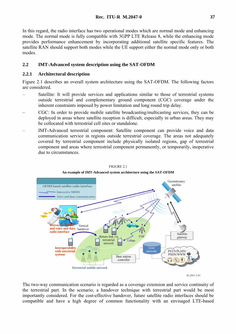
2.2.1 Architectural description
Figure 2.1 describes an overall system architecture using the SAT-OFDM. The following factors are considered.
– Satellite: It will provide services and applications similar to those of terrestrial systems outside terrestrial and complementary ground component (CGC) coverage under the inherent constraints imposed by power limitation and long round trip delay.
– CGC: In order to provide mobile satellite broadcasting/multicasting services, they can be deployed in areas where satellite reception is difficult, especially in urban areas. They may be collocated with terrestrial cell sites or standalone.
– IMT-Advanced terrestrial component: Satellite component can provide voice and data communication service in regions outside terrestrial coverage. The areas not adequately covered by terrestrial component include physically isolated regions, gap of terrestrial component and areas where terrestrial component permanently, or temporarily, inoperative due to circumstances.
FIGURE 2.1
An example of IMT-Advanced system architecture using the SAT-OFDM
M.2047-2-01
PSTN/PLMN/PSDN/WWW
Satellitegateway
Corenetwork
Base stationcontroller
Return link viaterrestrialnetwork
UrbanCGC
Verticalhandover
Terrestrial mobile network
Interoperabilitywith terrestrialsystems
Interactive MBMSand voice and dataradio interface
GeostationarysatelliteOFDM based satellite radio interface
Interactive MBMS
Voice and data communication
The two-way communication scenario is regarded as a coverage extension and service continuity of the terrestrial part. In the scenario, a handover technique with terrestrial part would be most importantly considered. For the cost-effective handover, future satellite radio interfaces should be compatible and have a high degree of common functionality with an envisaged LTE-based
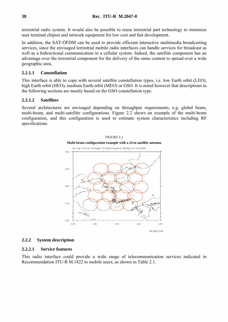
38 Rec. ITU-R M.2047-0
terrestrial radio system. It would also be possible to reuse terrestrial part technology to minimize user terminal chipset and network equipment for low cost and fast development.
In addition, the SAT-OFDM can be used to provide efficient interactive multimedia broadcasting services, since the envisaged terrestrial mobile radio interfaces can handle services for broadcast as well as a bidirectional communication in a cellular system. Indeed, the satellite component has an advantage over the terrestrial component for the delivery of the same content to spread over a wide geographic area.
2.2.1.1 Constellation
This interface is able to cope with several satellite constellation types, i.e. low Earth orbit (LEO), high Earth orbit (HEO), medium Earth orbit (MEO) or GSO. It is noted however that descriptions in the following sections are mostly based on the GSO constellation type.
2.2.1.2 Satellites
Several architectures are envisaged depending on throughput requirements, e.g. global beam, multi-beam, and multi-satellite configurations. Figure 2.2 shows an example of the multi-beam configuration, and this configuration is used to estimate system characteristics including RF specifications.
FIGURE 2.2
Multi-beam configuration example with a 24 m satellite antenna
M.2047-2-02
1.501.000.50 2.502.00
5.00
5.50
6.00
6.50
7.00
Sat. long = 116.0, lat = 0.0, height = 35 786 km. Created on: Wed May 13 11:24:20 2009
2.2.2 System description
2.2.2.1 Service features
This radio interface could provide a wide range of telecommunication services indicated in Recommendation ITU-R M.1822 to mobile users, as shown in Table 2.1.

Rec. ITU-R M.2047-0 39
TABLE 2.1
Supportable services
User experience class
Service class Example services
Conversational Basic conversational Voice telephony (including VoIP) Emergency calling Push-to-talk
Rich conversational Videoconference High-quality video telephony Remote collaboration e-education (e.g. video call to teacher) Consultation (e.g. video interaction with doctor) Mobile commerce
Conversational low delay Interactive gaming Consultation Priority service
Interactive Interactive high delay e-education (e.g. data search) Consultation (e.g. data search) Internet browsing Mobile commerce Location-based services ITS-enabled services
Interactive low delay Emergency calling e-mail (IMAP server access) Remote collaboration (e.g. desktop sharing) Public alerting (e.g. with feedback) Messaging (instant messaging) Mobile broadcasting/multicasting (mobile interactive personalized TV) Interactive gaming
Streaming Streaming live Emergency calling Public alerting e-education (e.g. remote lecture) Consultation (e.g. remote monitoring), Machine-to-machine (e.g. observation) Mobile broadcasting/multicasting Multimedia
Streaming non-live Mobile broadcasting/multicasting e-education (e.g. education movies) Multimedia Mobile commerce Remote collaboration

40 Rec. ITU-R M.2047-0
TABLE 2.1 (end)
User experience class
Service class Example services
Background Background Messaging, Video messaging Public alerting e-mail (transfer RX/TX, e.g. POP) Machine-to-machine File transfer/download e-education (file download/upload) Consultation (file download/upload) Internet browsing Location-based service
Quality of service (QoS) for various telecommunication services supported by this interface would be different from that in the terrestrial component of IMT-Advanced due to inherent satellite features such as long round trip delay. In this interface, maximum transfer delay of one way for the real time services at the bearer transport level could be less than 400 ms in the range of values 1 × 10⁻³ to 1 × 10⁻⁷ of BER.
2.2.2.2 System features
This radio interface is based on the key technical characteristics listed in Table 2.2.
TABLE 2.2
Key technical characteristics of the SAT-OFDM
Multiple-access scheme OFDMA (downlink), SC-FDMA (uplink)
Duplex scheme Frequency division duplexing (FDD)
Chip rate A multiple or submultiple of 3.84 Mcps
subcarrier spacing 15 kHz
Carrier spacing 1.3, 3, 5, 10, 15, 20 MHz
Frame length 10 ms
Inter-spot synchronization No accurate synchronization needed (Accurate synchronization needed for inter-beam coordination)
Multi-rate/Variable-rate scheme Variable modulations and coding rates + multi-layer
Channel coding scheme Convolutional coding 1/3 Turbo coding 1/3
2.2.2.3 Terminal features
The user equipment may be of various types: hand-held, portable, vehicular, transportable or aeronautical. The data rate and mobility restriction for each type of terminal are described in Table 2.3. For the maximum capacity assessment it is necessary to distinguish data rates of the forward link from those of the return link.

Rec. ITU-R M.2047-0 41
TABLE 2.3
Mobility restrictions for each terminal type
Terminal types
Data rates of the applied services
(return link) (bps/(Hz·layer))
Data rates of the applied services (forward link)
(bps/(Hz·layer))
Nominal mobility restriction
(km/h)
Hand-held (class 3) ≤ 0.089 ≤ 1.556 500
Portable ≤ 1.156 ≤ 1.556 500
Vehicular ≤ 1.556 ≤ 1.556 500 (maximum 1 000)
Transportable ≤ 1.556 ≤ 1.556 Static
2.2.2.4 Handover
This radio interface will support handover of communications from one satellite radio channel to another. The handover strategy is mobile-assisted network-decided handover.
Only hard handover is supported.
The following handover types are the most common in the system.
Beam handover
The UE periodically measures the level of the reference symbol C/(N + I) coming from adjacent beams and report such information to the satellite RAN. Based on the measurement reports, the serving satellite beam starts handover preparation which may involve exchange of signalling between serving and target beams and admission control of the UE in the target beam. Upon successful handover preparation, the handover decision is made and consequently, the handover command will be sent to the UE. The connection between UE and the serving beam will be released, then the UE attempts to synchronize and access the target beam by using the random access channel.
Inter-satellite handover
The procedure is analogous to that of inter-beam handover. The only difference is that the UE has also to search for different satellite specific reference symbol identities.
Inter-frequency handover
Inter-frequency handover may not generally be needed. This handover is decided by the satellite RAN without any support by the UE (i.e. this handover type is not a mobile-assisted handoff).
On the reverse link, the satellite RAN can instead combine all signals received from the same UE through different beams and/or satellites.
2.3 RF specifications
2.3.1 Satellite (space station)
Satellite characteristics considered in performance evaluation are summarized in Table 2.4.

42 Rec. ITU-R M.2047-0
TABLE 2.4
Satellite multi-beam architecture with 24 m satellite antenna
Number of spot beams 20
Downlink frequency (satellite to UE) (MHz) 2 170-2 200
Polarisation LHCP or RHCP
On board e.i.r.p. per carrier (dBW) 73
Uplink frequency (UE to satellite) (MHz) 1 980-2 010
Polarisation LHCP or RHCP
Rx Antenna gain (dB) ≤ 50
2.3.2 Mobile earth station (MES)
The mobile earth station is also named User Equipment (UE). The UE may be of several types:
3G standardized handset: the use in satellite environment requires adaptation for frequency agility to the MSS frequency band. The basic assumption is UE power class 1, 2 and 3, equipped with standard omni-directional antenna.
Portable: the portable configuration is built with a notebook PC to which an external antenna is appended.
Vehicular: the vehicular configuration is obtained by mounting an RF module on a car roof connected to the UE in the cockpit.
Transportable: the transportable configuration is built with a notebook of which the cover contains flat patch antennas (manually pointed towards the satellite).
Aeronautical: aeronautical configuration is built by mounting an antenna on top of the fuselage.
FIGURE 2.3
UE configuration
M.2047-2-03
Handset Portable Vehicular Transportable Aeronautical
The power and gain characteristics for four UE configurations are summarized in Table 2.5.

Rec. ITU-R M.2047-0 43
TABLE 2.5
UE characteristics
UE type Maximum transmit
power Reference
antenna gain Maximum
e.i.r.p. System temp.
G/T
3G Handset
Class 1 2 W (33 dBm) 0 dBi 3 dBW 290 K –24.6 dB/K
Class 2 500 mW (27 dBm) –3 dBW
Class 3 250 mW (24 dBm) –6 dBW
Portable 2 W (33 dBm) 2 dBi 5 dBW 200 K –21 dB/K
Vehicular 8 W (39 dBm) 4 dBi 13 dBW 250 K –20 dB/K
Transportable 2 W (33 dBm) 14 dBi 17 dBW 200 K –9 dB/K
2.4 Baseband specifications
2.4.1 Multiple access
The contents in this section are normatively referenced by clause 4.2.1 of TTAT.3G-36.2011, provided by TTA.
In addition, the followings are specified in order to adapt satellite specific conditions or performance enhancement in the satellite system.
To support transmission in paired 2 GHz band spectrum, one duplex mode is supported: Frequency Division Duplex (FDD), supporting full duplex and half duplex operation.
In downlink of enhancing mode, single-carrier frequency division multiplexing (SC-FDM) with a cyclic prefix is also supported. Details on this can be referred to § 2.4.6.6.
In uplink of enhancing mode, resource blocks narrower than 180 kHz are also supported for power-limited handheld terminals in uplink. Details on this can be referred to § 2.4.6.5.
2.4.2 Overall baseband transmission description
Overall downlink and uplink transmissions of the SAT-OFDM are described in Figs 2.4 and 2.5, respectively. The SAT-OFDM has basically the same transmission blocks with 3GPP LTE release eight radio interface for commonality but can also modify some blocks or add new blocks in order to adopt satellite-specific features.
1 Standard TTAT 3G-36.201 is the transposed document of 3GPP TS 36.201 http://committee.tta.or.kr/include/Download.jsp?filename=stnfile/TTAT.3G-36.201(R8-8.3.0).zip. TTA is one of the identified Transposing Organizations of 3GPP LTE(-Advanced) specifications.

44 Rec. ITU-R M.2047-0
FIGURE 2.4
Downlink transmissions in the SAT-OFDM
M.2047-2-04
TB 24-bit CRC attachmentcode block segmentation
Channel decoding
Code block segmentation
Rate dematching
Demodulator (LLR)
Layer demapping
Equalizer
Resource block demapping
Deprecoding
Serial to parallel
Remove cyclic prefix
Receiver
Transport block
Code block aggregation24-bit CRC check
Transport block
Channel coding (turbo 1/3)
Rate matching(bit selection and pruning)
Code block concatenation
Symbol mapper
Layer mapping
Precoding
Resource block mapping
Parallel to serial
Cyclic prefix attachment
Satellite channel
Channelestimator
FFTIFFT

Rec. ITU-R M.2047-0 45
FIGURE 2.5
Uplink transmissions in the SAT-OFDM
M.2047-2-05
TB 24-bit CRC attachmentcode block segmentation
Channel decoding
Code block segmentation
Rate dematching
Demodulator (LLR)
Layer demapping
Equalizer
Resource block demapping
Deprecoding
Serial to parallel
Remove cyclic prefix
Receiver
Transport block
Code block aggregation24-bit CRC check
Transport block
Channel coding (turbo 1/3)
Rate matching(bit selection and pruning)
Code block concatenation
Symbol mapper
Layer mapping
Precoding
Resource block mapping
Parallel to serial
Cyclic prefix attachment
Satellite channel
Channelestimator
FFTIFFT
DTF IDTF
2.4.3 Physical channels and timing relations
The following physical channels are defined in the SAT-OFDM.
– Downlink
• Physical channels: user data, control, information
– PDSCH (Physical Downlink Shared Channel)
– PMCH (Physical Multicast Channel)
– PDCCH (Physical Downlink Control Channel)

46 Rec. ITU-R M.2047-0
– PBCH (Physical Broadcast Channel)
– PCFICH (Physical Control Format Indicator Channel)
– PHICH (Physical Hybrid ARQ Indicator Channel)
• Physical signals: cell search, channel estimation
– RS (Reference Signal)
– SCH (Synchronization signal)
– Uplink
• Physical channels: user data, control
– PUSCH (Physical Uplink Shared Channel)
– PUCCH (Physical Uplink Control Channel)
– PSRACH (Physical Satellite Random Access Channel)
• Physical signals: channel estimation
– RS (Reference Signal)
2.4.3.1 Frame structure
The contents in this section are normatively referenced by clause 4 of TTAT.3G-36.2112, provided by TTA.
In addition, in order to adapt satellite specific conditions or performance enhancement in the satellite system, only frame structure type 1 is supported, applicable to FDD.
Figures 2.6 and 2.7 show downlink and uplink frame structures of the SAT-OFDM with seven OFDM symbols at normal cyclic prefix, respectively.
FIGURE 2.6
Downlink frame structure of the SAT-OFDM
M.2047-2-06
2 048160 144 144 144 144 144 144 (x Ts)2 048 2 048 2 0482 048 2 048 2 048
1
No.1
CP CP CP CP CP CP0 2 53 4 6
The cyclic prefix is created by prepending eachsymbol with a copy of the end of the symbol
etc.
1 sub-frame
= 10 ms
= 2 slots
Ts = 1/(15 000 2 048) = 32.6 ns×
1 slot
= 0.5 ms
= 15 360 Ts
N OFDM symbols (= 7 OFDM symbols at normal CP)symb
S-SCH - Secondary synchronization signal
PBCH - Physical broadcast channel
PDCCH - Physical downlink control channel
PDSCH - Physical downlink shared channelRS - Reference signal
0
No.2 No.3 No.4 No.5 No.6 No.7 No.8 No.9 No.11No.10 No.12 No.13 No.14 No.15 No.16 No.17 No.18 No.19No.0
1 43 5 62 1 20 3 4 5 6
1 Frame= 10 ms= 10 sub-frames
P-SCH - Primary synchronization signal
DL
CP
2 Standard TTAT.3G-36.211 is the transposed document of 3GPP TS 36.211 http://committee.tta.or.kr/include/Download.jsp?filename=stnfile/TTAT.3G-36.211(R8-8.6.0).zip.

Rec. ITU-R M.2047-0 47
FIGURE 2.7
Uplink frame structure of the SAT-OFDM
M.2047-2-07
2 048160 144 144 144 144 144 144 (x Ts)2 048 2 048 2 0482 048 2 048 2 048
1
No.1
CP CP CP CP CP CP0 2 53 4 6
The cyclic prefix is created by prepending eachsymbol with a copy of the end of the symbol
etc.
1 sub-frame
= 10 ms
= 2 slots
Ts = 1/(15 000 2 048) = 32.6 ns×
1 slot
= 0.5 ms
= 15 360 Ts
N OFDM symbols (= 7 OFDM symbols at normal CP)symb
PUSCH - Physical uplink shared channel
Demodulation reference signal
0
No.2 No.3 No.4 No.5 No.6 No.7 No.8 No.9 No.11No.10 No.12 No.13 No.14 No.15 No.16 No.17 No.18 No.19No.0
1 43 5 62 1 20 3 4 5 6
1 Frame= 10 ms
= 10 sub-frames
UL
CP
2.4.3.2 Uplink physical channels
The contents in this section are normatively referenced by clause 5.1 of TTAT.3G-36.211, provided by TTA.
2.4.3.2.1 Slot structure and physical resources
2.4.3.2.1.1 Resource grid
The contents in this section are normatively referenced by clause 5.2.1 of TTAT.3G-36.211, provided by TTA.
2.4.3.2.1.2 Resource elements
The contents in this section are normatively referenced by clause 5.2.2 of TTAT.3G-36.211, provided by TTA.
2.4.3.2.1.3 Resource blocks
The contents in this section are normatively referenced by clause 5.2.3 of TTAT.3G-36.211, provided by TTA.
In addition, the followings are specified in order to adapt satellite specific conditions or performance enhancement in the satellite system.
In enhancing mode, a narrow-band physical resource block in the uplink is also supported, corresponding to 2 slots and 90 kHz, 4 slots and 45 kHz, and 6 slots and 30 kHz in the time and frequency domains, respectively.
2.4.3.2.2 Physical uplink shared channel
The contents in this section are normatively referenced by clause 5.3 of TTAT.3G-36.211, provided by TTA.
2.4.3.2.2.1 Scrambling
The contents in this section are normatively referenced by clause 5.3.1 of TTAT.3G-36.211, provided by TTA.

48 Rec. ITU-R M.2047-0
2.4.3.2.2.2 Modulation
The contents in this section are normatively referenced by clause 5.3.2 of TTAT.3G-36.211, provided by TTA.
In addition, in order to adapt satellite specific conditions or performance enhancement in the satellite system, 64QAM modulation scheme is not supported.
TABLE 2.6
Uplink modulation schemes
Physical channel Modulation schemes
PUSCH QPSK, 16QAM
2.4.3.2.2.3 Transform precoding
The contents in this section are normatively referenced by clause 5.3.3 of TTAT.3G-36.211, provided by TTA.
2.4.3.2.2.4 Mapping to physical resources
The contents in this section are normatively referenced by clause 5.3.4 of TTAT.3G-36.211, provided by TTA.
In addition, in order to adapt satellite specific conditions or performance enhancement in the satellite system, TDD related operation is not considered.
2.4.3.2.3 Physical uplink control channel
The contents in this section are normatively referenced by clause 5.4 of TTAT.3G-36.211, provided by TTA.
2.4.3.2.4 Reference signals
The contents in this section are normatively referenced by clause 5.5 of TTAT.3G-36.211, provided by TTA.
In addition, in order to adapt satellite specific conditions or performance enhancement in the satellite system, TDD operation for sounding reference signal in clause 5.5.3 of TTAT.3G-36.211 is not considered.
2.4.3.2.5 SC-FDMA baseband signal generation
The contents in this section are normatively referenced by clause 5.6 of TTAT.3G-36.211, provided by TTA.
2.4.3.2.6 Physical random access channel
2.4.3.2.6.1 Operation in normal mode
The contents in this section are normatively referenced by clause 5.7.1 of TTAT.3G-36.211, provided by TTA.
In addition, in order to adapt satellite specific conditions or performance enhancement in the satellite system, a physical random access channel for TDD is not considered.

Rec. ITU-R M.2047-0 49
2.4.3.2.6.2 Operation in enhancing mode
In enhancing mode, new RA preambles are defined for system capacity improvement in satellite environments. The parameter values are listed in Table 2.7, and the values are determined by the random access configuration. The preamble format is controlled by higher layers.
TABLE 2.7
Random access preamble parameters
Preamble format CPT SEQT
4 sT⋅⋅62409 sT⋅⋅ 245763
5 sT⋅⋅ 210243 sT⋅⋅ 245766
The transmission of a random access preamble, if triggered by the MAC layer, is restricted to certain time and frequency resources. These resources are enumerated in increasing order of the subframe number within the radio frame and the physical resource blocks in the frequency domain such that index 0 corresponds to the lowest numbered physical resource block and subframe within the radio frame. PRACH resources within the radio frame are indicated by a PRACH resource index.
The physical layer random access is configured by two preamble formats listed in Table 2.7 and the subframes in which random access preamble transmission is allowed for a given configuration in frame structure type 1. The configuration index parameter of PRACH is given by higher layers. The start of the random access preamble shall be aligned with the start of the corresponding uplink subframe at the UE. For some PRACH configurations the UE may for handover purposes assume an absolute value of the relative time difference between radio frame i in the current beam and the target beam.
The random access opportunities for each PRACH configuration shall be alighted in time first and then in frequency if and only if time multiplexing is not sufficient to hold all opportunities of a PRACH configuration needed for a certain PRACH density value per 10 ms without overlap in time.
For preamble formats 5 and 6, the frequency multiplexing shall be done according to:
−−−
=
+
=otherwise,,
222
,02mod if,2
2
RARAoffset PRB
ULRB
RARARA
offset PRBRAPRB f
nN
ff
nn
where:
ULRBN : number of uplink resource blocks
fRA: PRACH resource frequency index within the considered time-domain location
RAPRBn : first physical resource block allocated to the PRACH opportunity considered
and where the parameter prach-Frequency Offset

50 Rec. ITU-R M.2047-0
RA
offset PRBn : first physical resource block available for PRACH expressed as a physical
resource block number configured by higher layers and fulfilling
20 ULRB
RAPRBoffset −≤≤ Nn .
The random access preambles are generated from Zadoff-Chu sequences with zero correlation zone, generated from one or several root Zadoff-Chu sequences. The network configures the set of preamble sequences which the UE is allowed to use.
There are 64 preambles available in each beam. The set of 64 preamble sequences in a beam is found by including the first, in order of increasing cyclic shift, all the available cyclic shifts of a root Zadoff-Chu sequence with the logical index RACH_ROOT_SEQUENCE, where RACH_ROOT_SEQUENCE is broadcasted as part of the System Information. Additional preamble sequences, in case 64 preambles cannot be generated from a single root Zadoff-Chu sequence, are obtained from the root sequences with the consecutive logical indexes until all the 64 sequences are found. The logical root sequence order is cyclic.
The time-continuous random access signal s(t) is defined by
( ) ( )( ) ( ),)(1
0
21
0
2
,PRACH
ZCCPRA2
10
ZCZC
−
=
−Δ++ϕ+π−
=
π−⋅⋅β=
N
k
TtfkKkjN
n
N
nkj
vu eenxts
where:
CPSEQ0 TTt +<≤
PRACHβ : amplitude scaling factor in order to conform to the transmit power
)(, nx vu : random access preambles
2RBsc
ULRB
RBsc
RAPRB0 NNNnk −=
The location in the frequency domain is controlled by the parameter RAPRBn which is the first
physical resource block allocated to the PRACH opportunity considered. The factor RAffK ΔΔ= accounts for the difference in subcarrier spacing between the random access preamble and uplink data transmission. The variable RAfΔ , the subcarrier spacing for the random access preamble, and the variable ϕ , a fixed offset determining the frequency-domain location of the random access preamble within the physical resource blocks, are both given by Table 2.8.
TABLE 2.8
Random access baseband parameters
Preamble format RAfΔ ϕ
4-5 416.67 Hz –6
2.4.3.2.7 Modulation and up-conversion
The contents in this section are normatively referenced by clause 5.8 of TTAT.3G-36.211, provided by TTA.

Rec. ITU-R M.2047-0 51
2.4.3.3 Downlink physical channels
The contents in this section are normatively referenced by clause 6.1 of TTAT.3G-36.211, provided by TTA.
2.4.3.3.1 Slot structure and physical resources
The contents in this section are normatively referenced by clause 6.1 of TTAT.3G-36.211, provided by TTA.
In addition, in order to adapt satellite specific conditions or performance enhancement in the satellite system, § 6.2.6 regarding guard period for TDD operation is not considered.
2.4.3.3.2 General structure for downlink physical channels
The contents in this section are normatively referenced by clause 6.3 of TTAT.3G-36.211, provided by TTA.
TABLE 2.9
Modulation scheme
Physical channel Modulation schemes
PDSCH QPSK, 16QAM
PMCH QPSK, 16QAM
In addition, the followings are specified in order to adapt satellite specific conditions or performance enhancement in the satellite system.
64QAM modulation scheme is not supported.
In enhancing mode, the following steps are additionally defined for the baseband signal representing a downlink physical channel:
– long-time interleaving of the complex-valued modulation symbols over several subframes (Details are specified in § 2.4.6.1);
– generation of complex-valued time-domain SC-FDM signal for each antenna port (Details are specified in § 2.4.6.6).
In enhancing mode, precoding for cooperative transmit diversity with complementary ground components (CGCs) is also added for performance enhancement in an integrated satellite CGC configuration (Details are specified in § 2.4.6.4).
2.4.3.3.3 Physical downlink shared channel
The contents in this section are normatively referenced by clause 6.4 of TTAT.3G-36.211, provided by TTA.
2.4.3.3.4 Physical multicast channel
The contents in this section are normatively referenced by clause 6.5 of TTAT.3G-36.211, provided by TTA.
2.4.3.3.5 Physical broadcast channel
The contents in this section are normatively referenced by clause 6.6 of TTAT.3G-36.211, provided by TTA.

52 Rec. ITU-R M.2047-0
2.4.3.3.6 Physical control format indicator channel
The contents in this section are normatively referenced by clause 6.7 of TTAT.3G-36.211, provided by TTA.
2.4.3.3.7 Physical downlink control channel
The contents in this section are normatively referenced by clause 6.8 of TTAT.3G-36.211, provided by TTA.
2.4.3.3.8 Physical hybrid ARQ indicator channel
The contents in this section are normatively referenced by clause 6.9 of TTAT.3G-36.211, provided by TTA.
2.4.3.3.9 Reference signal
The contents in this section are normatively referenced by clause 6.10 of TTAT.3G-36.211, provided by TTA.
2.4.3.3.9.1 Cell-specific reference signals
The contents in this section are normatively referenced by clause 6.10.1 of TTAT.3G-36.211, provided by TTA.
2.4.3.3.9.2 MBSFN reference signals
The contents in this section are normatively referenced by clause 6.10.2 of TTAT.3G-36.211, provided by TTA.
2.4.3.3.9.3 UE-specific reference signals
The contents in this section are normatively referenced by clause 6.10.3 of TTAT.3G-36.211, provided by TTA.
2.4.3.3.10 Synchronization signal
The contents in this section are normatively referenced by clause 6.11 of TTAT.3G-36.211, provided by TTA.
2.4.3.3.10.1 Primary synchronization signal
The contents in this section are normatively referenced by clause 6.11.1 of TTAT.3G-36.211, provided by TTA.
2.4.3.3.10.2 Secondary synchronization signal
The contents in this section are normatively referenced by clause 6.11.2 of TTAT.3G-36.211, provided by TTA.
2.4.3.3.11 OFDM baseband signal generation
The contents in this section are normatively referenced by clause 6.12 of TTAT.3G-36.211, provided by TTA.
2.4.3.3.12 Modulation and up-conversion
The contents in this section are normatively referenced by clause 6.13 of TTAT.3G-36.211, provided by TTA.

Rec. ITU-R M.2047-0 53
2.4.3.4 Timing
2.4.3.4.1 Uplink-downlink frame timing
The contents in this section are normatively referenced by clause 8 of TTAT.3G-36.211, provided by TTA.
In addition, the followings are specified in order to adapt satellite specific conditions or performance enhancement in the satellite system.
Resource allocation needs to be made to satisfy the uplink-downlink frame timing defined in clause 8 of TTAT.3G-36.211. Figure 2.8 illustrates a resource allocation method designed for this purpose, by considering satellite specific conditions. UE1 and UE2 represent terminals located at the beam edge and the centre, respectively. Therefore, UE1 and UE2 have the maximum and minimum round trip delays (RTDs), respectively, and thus ∆ , has the maximum value among all available ∆ , . The timing reference is set for uplink transmission with respect to the RTD of UE1. With this reference, UE1 can transmit its uplink signal as soon as the resource allocation information is received via the downlink, i.e. DI=0. On the other hand, for UEj, ∆ , is compensated by using the modified resource allocation method without any modification of the terrestrial LTE uplink-downlink timing. In fact, the scheduler in a satellite can get location information of each UE via its own random access trial. By using this information, the scheduler allocates available resources to the most appropriate subframes paired with a specific downlink subframe. For instance, as shown in Fig. 2.8, UE1 and UE2 receive downlink signal after t1/2 and t2/2, respectively, where ti is the RTD of UEi. The scheduler allocates available resources to the most adjacent uplink reference subframe just after the downlink signal reception and switching delay, tpro. Because the scheduler has information on ∆ , , the orthogonality problem can be resolved.
FIGURE 2.8
Resource allocation for uplink-downlink frame timing
M.2047-2-08
TimeFrame N Frame + 1N
Frame N...
... ...
Frame + 1N...
Frame N
Frame N
Frame N Frame + 1N
Frame + 1N
Frame + 1NFrame – 1N
Frame N Frame + 1N
Frame N Frame + 1N
Frame N Frame + 1N
SatelliteLocation
UE2
UE2
Reference
UE1
UE1
Satellite
10 ms
Subframes Subframes
1 ms
Uplink frameDownlink frame
... ...
... ...
... ...
... ...
... ...
... ...
...
DI = 0
τ2/2
DI < 1 ms
τ2/2
t /21
τ p-a
τ p-a
τ1/2
2.4.3.4.2 Timing relation between PRACH and PDCCH related AI
The uplink PRACH access frames are time-aligned with the reception of downlink PDCCH related to acquisition indicator (AI) access frame. Uplink access frame number n is transmitted from MES

54 Rec. ITU-R M.2047-0
τp-a subframes prior to the reception of downlink access frame number n, n=0, 1, …, 9. The PRACH/PDCCH timing relation is shown in Fig. 2.9. The transmission offset τoff shall be a value between the range of −τoff,max to τoff,max, where τoff,max is maximum transmission offset and is signalled by higher layers. The preamble-to-preamble distance τp-p shall be larger than or equal to the minimum preamble-to-preamble distance τp-p,min. In addition to τp-p,min, the preamble-to-AI distance τp-a is defined as follows:
– when AI_Transmission_Timing is set to 0, then τp-p,min = 300 subframes (thirty radio frames) and τp-a = 280 subframes (twenty-eight radio frames);
– when AI_Transmission_Timing is set to 1, then τp-p,min = 560 subframes (fifty-six radio frames) and τp-a = 540 subframes (fifty-four radio frames).
The parameter AICH_Transmission_Timing is signalled by higher layers.
FIGURE 2.9
Timing relation between PRACH and AI as seen at the MES
M.2047-2-09
One radio frame
Preamble
AIAI access framesRX at UE
AI access framesTX at UE τp-p
τoff
τp-a
Preamble
2.4.4 Channel multiplexing and coding
2.4.4.1 Mapping to physical channels
2.4.4.1.1 Uplink
The contents in this section are normatively referenced by clause 4.1 of TTAT.3G-36.2123, provided by TTA.
2.4.4.1.2 Downlink
The contents in this section are normatively referenced by clause 4.2 of TTAT.3G-36.212, provided by TTA.
2.4.4.2 Channel coding, multiplexing and interleaving
The contents in this section are normatively referenced by clause 5 of TTAT.3G-36.212, provided by TTA.
2.4.4.2.1 Generic procedure
2.4.4.2.1.1 CRC calculation
The contents in this section are normatively referenced by clause 5.1.1 of TTAT.3G-36.212, provided by TTA.
3 Standard TTAT.3G-36.212 is the transposed document of 3GPP TS 36.212 http://committee.tta.or.kr/include/Download.jsp?filename=stnfile/TTAT.3G-36.212(R8-8.6.0).zip.

Rec. ITU-R M.2047-0 55
2.4.4.2.1.2 Code block segmentation and code block CRC attachment
The contents in this section are normatively referenced by clause 5.1.2 of TTAT.3G-36.212, provided by TTA.
2.4.4.2.1.3 Channel coding
The contents in this section are normatively referenced by clause 5.1.3 of TTAT.3G-36.212, provided by TTA.
2.4.4.2.1.3.1 Tail biting convolutional coding
The contents in this section are normatively referenced by clause 5.1.3.1 of TTAT.3G-36.212, provided by TTA.
2.4.4.2.1.3.2 Turbo coding
The contents in this section are normatively referenced by clause 5.1.3.1 of TTAT.3G-36.212, provided by TTA.
2.4.4.2.1.4 Rate matching
2.4.4.2.1.4.1 Rate matching for turbo coded transport channels
The contents in this section are normatively referenced by clause 5.1.4.1 of TTAT.3G-36.212, provided by TTA.
2.4.4.2.1.4.2 Rate matching for convolutionally coded transport channels and control information
The contents in this section are normatively referenced by clause 5.1.4.2 of TTAT.3G-36.212, provided by TTA.
2.4.4.2.1.5 Code block concatenation
The contents in this section are normatively referenced by clause 5.1.5 of TTAT.3G-36.212, provided by TTA.
2.4.4.2.2 Uplink transport channels and control information
2.4.4.2.2.1 Random access channel
The contents in this section are normatively referenced by clause 5.2.1 of TTAT.3G-36.212, provided by TTA.
2.4.4.2.2.2 Uplink shared channel
The contents in this section are normatively referenced by clause 5.2.2 of TTAT.3G-36.212, provided by TTA.
In addition, the followings are specified in order to adapt satellite specific conditions or performance enhancement in the satellite system.
TDD related operation is not considered.
In enhancing mode, 5 bits of wideband CQI is also added as shown in Table 2.10. The addition is for channel quality information feedback with wideband CQI reports, and used for transmission modes 4 and 6.

56 Rec. ITU-R M.2047-0
TABLE 2.10
Wideband CQI field for enhancing mode
Field Bit width
Two antenna ports Four antenna ports
Rank = 1 Rank = 2 Rank = 1 Rank > 1
Wideband CQI codeword 0 5 5 5 5
Wideband CQI codeword 1 0 5 0 5
2.4.4.2.2.3 Uplink control information (UCI) on PUCCH
The contents in this section are normatively referenced by clause 5.2.3 of TTAT.3G-36.212, provided by TTA.
In addition, the followings are specified in order to adapt satellite specific conditions or performance enhancement in the satellite system.
TDD related operation is not considered.
In enhancing mode, the receiver memory (RM) field is added to HARQ-ACK (details are specified in § 2.4.6.10).
In enhancing mode, 5 bits of wideband CQI is also added as shown in Tables 2.11 and 2.12. Table 2.11 defines channel quality information feedback for wideband CQI reports, and it is used for transmission modes 1, 2, 3 and 7. Table 2.12 is used for transmission modes 4, 5 and 6.
TABLE 2.11
UCI field for enhancing mode (transmission mode 1, 2, 3 and 7)
Field Bit width
Wideband CQI 5
TABLE 2.12
UCI field for enhancing mode (transmission modes 4, 5 and 6)
Field
Bit width
Two antenna ports Four antenna ports
Rank = 1 Rank = 2 Rank = 1 Rank > 1
Wideband CQI 4 4 4 4
2.4.4.2.2.4 Uplink control information on PUCCH without UL-SCH data
The contents in this section are normatively referenced by clause 5.2.4 of TTAT.3G-36.212, provided by TTA.

Rec. ITU-R M.2047-0 57
2.4.4.2.3 Downlink transport channels and control information
2.4.4.2.3.1 Broadcast channel
The contents in this section are normatively referenced by clause 5.3.1 of TTAT.3G-36.212, provided by TTA.
2.4.4.2.3.2 Downlink shared channel, paging channel and multicast channel
The contents in this section are normatively referenced by clause 5.3.2 of TTAT.3G-36.212, provided by TTA.
2.4.4.2.3.3 Downlink control information (DCI)
The contents in this section are normatively referenced by clause 5.2.3 of TTAT.3G-36.212, provided by TTA.
In addition, the followings are specified in order to adapt satellite specific conditions or performance enhancement in the satellite system.
TDD related operation is not considered.
In enhancing mode, the number of indicator bits in DCI format 0 is changed for satellite carrier aggregation.
– New data indicator – 2 bits (increased to 2 bits from 1 bit in clause 5.3.3 of TTAT.3G-36.212).
In enhancing mode, the number of indicator bits in DCI formats 1, 1A, 1B, 1D, 2, 2A and 2B is changed for satellite HARQ and satellite carrier aggregation.
– HARQ process number – 9 bits (increased to 9 bits from 3 bits in clause 5.3.3 of TTAT.3G-36.212).
– New data indicator – 2 bits (increased to 2 bits from 1 bit in clause 5.3.3 of TTAT.3G-36.212).
2.4.4.2.3.4 Control format indicator (CFI)
The contents in this section are normatively referenced by clause 5.3.4 of TTAT.3G-36.212, provided by TTA.
2.4.4.2.3.5 HARQ indicator (HI)
The contents in this section are normatively referenced by clause 5.3.5 of TTAT.3G-36.212, provided by TTA.
2.4.5 Physical layer procedures
2.4.5.1 Beam search
The contents in this section are normatively referenced by clause 4.1 of TTAT.3G-36.2134, provided by TTA.
2.4.5.2 Timing synchronization
The contents in this section are normatively referenced by clause 4.1 of TTAT.3G-36.213, provided by TTA.
4 Standard TTAT.3G-36.213 is the transposed document of 3GPP TS 36.213 http://committee.tta.or.kr/include/Download.jsp?filename=stnfile/TTAT.3G-36.213(R8-8.6.0).zip.

58 Rec. ITU-R M.2047-0
In addition, the followings are specified in order to adapt satellite specific conditions or performance enhancement in the satellite system.
The resource allocation method for this transmission timing adjustments in satellite environments is specified in § 2.4.3.4.
2.4.5.3 Power control
2.4.5.3.1 Uplink power control
2.4.5.3.1.1 Operation in normal mode
The contents in this section are normatively referenced by clause 5.1 of TTAT.3G-36.213, provided by TTA.
2.4.5.3.1.2 Operation in enhancing mode
The uplink power control is based on both signal-strength measurements done by the terminal itself (open-loop power control), as well as measurements by the base station.
Even though the uplink uses orthogonal SC-FDMA access, high level of interference from neighbouring beams can still limit the uplink coverage if UEs in the neighbouring beams are not power controlled. The average inter-cell interference level received at the satellite is effectively reduced by the slow power control on each UE to compensate for path-loss and shadowing.
For the uplink, an event-based combined open-loop and closed-loop power control algorithm is applied.
The uplink power control adjusts the UE transmission power in order to keep the transmission power spectral density (PSD) at a given PSD target for each MCS, PSDtarget. The uplink power control shall be performed while the UE transmission power is below the maximum allowed output power.
Any change in the uplink transmission power shall take place immediately before the start of the frame. The change in power with respect to its previous value is derived by the UE and is denoted by ΔUP (dB).
The satellite-RAN should estimate power spectral density PSDest of the received uplink SRS, generate TPC commands, and transmit the commands once per more than one radio frame according to the following rule:
Define the variable:
Δε(i): PSDest−PSDtarget for a given MCS level
Δp(i): power control step whose value is determined according to the TPC_cmd for the ith frame, where the step sizes are [–1 dB 0 dB +1 dB +3 dB] under the control of the Satellite-RAN
Nframe: loop delay expressed in frames
and then, Δp(i) is generated by using Δε(i) and the past Nframe power control steps Δp(k), k = i − Nframe − 1, ..., i − 1 as follows:
Compute:
)),1()(()( 1, −−χ+Δ=Δ εε iPSDiPSDGi SRSSRSc
where the loop delay compensation indicator, G1 (0 ≤ G1 ≤ 1) is the higher layer parameter and is identical for all MESs in the same beam. When SRS can be used for channel estimation, the value χ has 1, otherwise χ is zero.

Rec. ITU-R M.2047-0 59
– if |Δε,c| < εT and Δε,c < 0, Δp(i) = 1 dB
– if |Δε,c| < εT and Δε,c > 0, Δp(i) = 0 dB
– if |Δε,c| < εT and Δε,c < 0, Δp(i) = 3 dB
– if |Δε,c| > εT and Δε,c > 0, Δp(i) = –1 dB.
The MES adjusts the transmit power of the uplink DSCH with a step of ΔUP (dB) using two most recently received power control steps, Δp(i) and Δp(I − 1) as follows:
ΔUP = Δp(i)−αΔp(I − 1)
where α is identical to that used in the serving beam and is signalled by the higher layer.
2.4.5.3.2 Downlink power control
2.4.5.3.2.1 Operation in normal mode
The contents in this section are normatively referenced by clause 5.2 of TTAT.3G-36.213, provided by TTA.
2.4.5.3.2.2 Operation in enhancing mode
Dynamic power control is applied to dedicated control channels addressed to a single UE or a group of UEs. No feedback of TPC commands is provided on the uplink, and power allocation is based on the downlink channel quality feedback from the UEs. Different power levels can be allocated to different resource blocks used for data transmission in a semi-static way to support inter-beam interference coordination (IBIC). Moreover, two different power levels can be defined on OFDM symbols used for data transmission within a subframe to improve satellite RAN power utilization. However, different power levels across antenna ports to resolve the spatial domain power imbalance are not permitted.
In order to decide suitable MCS level from the downlink channel quality feedback, UE may employ a prediction algorithm which estimates the future channel condition after the round trip delay. Prediction for the channel variation can be implemented by observing the trace of the past channel variations of the common channel in the active set. In order to support UEs which employ the prediction algorithm, a nominal round trip delay of the beam to which the UE belongs is signalled by higher layers. The predicted channel variation after round trip delay, Δpred, is used by the satellite RAN.
)),1()(( −−=Δ ++−++− iPSDiPSDG SCHPBCHRSCSISCHPBCHRSCSIpred
where the prediction gain, G is the higher layer parameter and may be different for each MES in the same beam.
Basically, adaptive modulation and coding (AMC) scheme is applied in downlink transmission instead of power control. But power control can be applied in the downlink transmission to keep low PAPR as follows.
– Step 1: Monitor the large scale fading values (Lk) experienced by UEs.
– Step 2: Count the number of UEs (Nu) satisfying Lk > B0.
– Step 3: If Nu < B1, count the number of total subcarriers (Nc) used by Nu UEs.
Otherwise, AMC mode operation is done.
– Step 4: If Nc < B2, power control mode is done.
Otherwise, AMC mode operation is done.
where thresholds, B0, B1 and B2 are signalled by high layers.

60 Rec. ITU-R M.2047-0
2.4.5.4 Random access procedure
The contents in this section are normatively referenced by clause 6 of TTAT.3G-36.213, provided by TTA.
In addition, the followings are specified in order to adapt satellite specific conditions or performance enhancement in the satellite system.
A random access procedure for a GPS mounted UE is defined. A GPS mounted UE can predict the amount of round trip delay based on its own location information. After adjusting UE uplink timing to within a fraction of the cyclic prefix of a random access preamble, it performs the random access transmission with the same preamble formats as that of terrestrial LTE. The UE should provide the adapted uplink timing information to the satellite RAN by selecting an appropriate preamble sequence group from Table 2.13. Some of a total of 64 sequences are configured for contention-based random access and their grouping information is signalled by the high layer.
TABLE 2.13
RA preamble sequence group
RTD difference from a beam centre Used preamble sequence group
RTD difference ≤ 1 ms Preamble sequence group 1
RTD difference ≤ 2 ms Preamble sequence group 2
RTD difference ≤ 3 ms Preamble sequence group 3
RTD difference ≤ 4 ms Preamble sequence group 4
Random access via the sequence grouping allows the satellite RAN to estimate and, if needed, adjust the UE uplink scheduling timing. The steps of the adjusting UE uplink scheduling timing are as follows:
– The satellite RAN estimates the RTD of UE using the received random access preamble and Table 2.13.
– The satellite RAN schedules the access timing of UE using the estimated RTD.
When the satellite RAN successfully received a random access preamble, it sends a random access response indicating the successfully received preamble(s) along with the time advance (TA) and uplink resource allocation information considering RTD to the UE as in Fig. 2.10.

Rec. ITU-R M.2047-0 61
FIGURE 2.10
The contention-based random access procedures with preamble sequence groups
M.2047-2-10
UE eNB
1. Preamble on PRACH
2. Preamble response onPDCCH + DL-SH
3. PUSCH transmission includingcontention resolution identity
4. Contention resolution message
Contention based RA
Preamble sequence selectionwithin the sequence group
corresponding to UE location
Estimation of RTD informationon RA UEs from the used
sequence group
2.4.6 Satellite-specific features for performance enhancement
The SAT-OFDM has a high degree of commonality with the LTE-based terrestrial radio interface but it also has a number of different features. Those features, which are necessary to reflect the satellite-specific characteristics, such as long round trip delay, are implemented. For this purpose, the following techniques are included for enhancing mode operation.
2.4.6.1 Long-time interleaver for efficient AMC operation
This scheme is used for an efficient AMC operation in satellite environment.
Considering the RTD of a GSO system, the AMC of the satellite systems cannot effectively counteract to short-term fading. A long time-interleaving technique can be used in conjunction with AMC to compensate short-term fading.
After turbo coding with mother code rate of 1/3, rate mating is applied to produce various code rates for adaptive usage. Interleaving is applied to data blocks composed of resource elements (REs) of traffic data after the baseband modulation and before resource block (RB) mapping and IFFT for OFDM modulation.
Figure 2.11 shows an example of data formation for interleaving and OFDM symbol mapping before IFFT, when the interleaver size is 120 ms. The example assumes that a single user is allocated to six RBs, i.e. 720 resource elements (REs) with 1.4 MHz bandwidth. Traffic data contained in a codeword of 1 ms is divided into 120 blocks for interleaving, and each block is called an Interleaving unit (IU). Figure 2.12 shows the configuration of the corresponding square type block interleaver which can be used to implement interleaving in Fig. 2.11. Although Fig. 2.12 shows a block type interleaver, an equivalent convolutional type interleaver can be used to reduce memory size of the interleaver. With the interleaver, a codeword consists of 120 IUs, and an IU contains different number of REs depending on the allocated bandwidth. The notation C1
2 in a single IU in Fig. 2.12 represents the second segment of the first codeword. When interleaving is operated, the transmission will start from the first element of the first column, and continue to the last element of the same column. Then, it will continue from the first element of the second column with the same manner up to the last element of the last column. Table 2.14 represents interleaver parameter examples according to the allocated bandwidth.

62 Rec. ITU-R M.2047-0
FIGURE 2.11
An example of data formation for interleaving and OFDM symbol mapping
M.2047-2-11
Block 1 Block 2 Block 3 Block 4 Block 5 Block 118 Block 119 Block 120 P-SCH S-SCH PBCH PDCCH RS
P-SCH - Primary synchronization signal
S-SCH - Secondary synchronization signal
PBCH - Physical broadcast channel
PDCCH - Physical downlink control channel
RS - Reference signal
Traffic data blocks used for interleaving
6 REs
Interleaving with 120 ms data
OFDM symbol mapping with interleaved traffic data and control information72 14 REs/1 TTI ( = 1 ms), 1.4 MHz×
Slot 1 Slot 2
72 REs
OFDMsymbol 1
OFDMsymbol 2CP CP CP CP
OFDMsymbol 3
OFDMsymbol 4
OFDMsymbol 5
OFDMsymbol 6
OFDMsymbol 7CP CP CP CP CP CP CP CP CP
OFDMsymbol 8
OFDMsymbol 9
OFDMsymbol 10
OFDMsymbol 11
OFDMsymbol 12
OFDMsymbol 13
OFDMsymbol 14
RE
RE
RE
RE
1 ms
Data formation for interleaving
RE
RE
RE
RE
CP
FIGURE 2.12
An example of square type block interleaver
M.2047-2-12
120
IUs
120 IUs
C11
C21
C31
C41
C51
C81
C91
C61
C71
C12 C1
3 C14 C1
5 C16 C1
7 C18 C1
9 C110
C22 C2
3 C24 C2
5 C26 C2
7 C28 C2
9 C210
C32 C3
3 C34 C3
5 C36 C3
7 C38 C3
9 C310
C42 C4
3 C44 C4
5 C46 C4
7 C48 C4
9 C410
C1119 C1
120
C2119 C2
120
C3119 C3
120
C4119 C4
120
C1141
C1151
C1161
C1171
C1181
C1191
C1201

Rec. ITU-R M.2047-0 63
TABLE 2.14
Long-time interleaver parameter examples
Allocated bandwidth (MHz)
No. of RBs No. of REs Interleaver size (ms)
No. of REs in an IU
No. of IUs/ms
1.4 6 720
120 6 120
360 2 360
720 1 720
3 15 1 800
120 15 180
360 5 360
1 800 1 1 800
5 25 3 000 120 25 120
10 50 6 000 120 50 120
15 75 9 000 120 75 120
20 100 12 000 120 100 120
The interleaver information based on resource allocation type and memory information is exchanged between S-eNodeBs and UEs for long-time interleaving. The interleaver information indicates an interleaver identifier (ID) representing an interleaver size (N) and interleaving unit (IU). Table 2.15 shows the interleaver IDs.
TABLE 2.15
Long-time interleaver ID
Interleaver ID N IU
0001 120 1
0010 120 2
0011 120 3
0100 120 4
0101-1111 Reserved Reserved
Especially, the symbol-interleaving process comprises interleaving the symbol-level data using an interleaver having a maximum size of 120 IUs with respect to a single RB when the resource allocation type information includes the type 2 defined in clause 7.1.6 of TTAT.3G-36.213.
The application of the (long-time) symbol interleaver is based on service information. The long-time interleaver is only applicable to non-real-time services.
For continuous transmission with the long interleaving process, a padding bits timer is applied. When no data is input to the interleaving buffer until the padding bits timer is expired, the random data may be input to the long-time interleaver. That is, when the interleaving buffer does not include the new data and the timer is yet to expire, the data is not transmitted.
2.4.6.2 Fractional frequency reuse within multi-beams
This scheme is used to support broadband satellite services as well as to increase spectral efficiency in a multi-beam satellite system. It can also be applied without any modification of LTE chipset in normal mode because it is implementation specific.

64 Rec. ITU-R M.2047-0
For fractional frequency reuse (FFR) within multi-beams, the satellite RAN shall obtain UE location information in order to distinguish beam centre UEs from beam edge UEs. The location information is determined during the random access trial of an UE, on the help of GPS mounted in an UE, or with the received SINR values from the target and adjacent beams into an UE.
When the UE timing information from the random access trial is obtained by satellite RAN, it is given as follows:
– if θ1 < TRTD_difference < θ2, the UE is located at the beam centre region;
– otherwise, the UE is located at the beam edge region,
where TRTD_difference is round trip delay difference between the target UE and the UE that has minimum round trip delay within the target beam, and the threshold values, θ1 and θ2 are high layer parameters.
When the received downlink SINRs from target and adjacent beams are estimated by a UE, the UE timing information can be also given as follows:
– if θ3 < , the UE is located at the beam centre region,
– otherwise, the UE is located at the beam edge region,
where the threshold value, θ3 is a high layer parameter.
The location information obtained by the UE shall be sent to the satellite RAN as follows:
– if the UE is located at the beam centre region, “0” is sent;
– if the UE is located at the beam edge region, “1” is sent.
In case of application of the fractional frequency reuse in a multi-beam satellite system, each beam is partitioned into two regions and each frame should be divided into two time sections, T1 and T2, in each beam, as shown in Fig. 2.13. The first section, T1 is allocated to UEs in the beam centre, and all subcarriers are used for transmission during this time period. On the other hand, the second time section, T2 is allocated to UEs in the beam edge. During this time period, only identified fractional subcarriers out of whole subcarriers are used.
The identification of fractional subcarriers is made by MAC layers. The values, T1 and T2 are determined by high layer, considering total system throughput and inter-beam interference.

Rec. ITU-R M.2047-0 65
FIGURE 2.13
Frame structure for fractional frequency reuse
M.2047-2-13
UEsin beam centre
UEsin beam centre
UEsin beam edge
UEsin beam edge
T2T1 T1
One frame One frame
Beam 1
3
2
1
4
5
67
Subcarrier groupnumber
UEsin beam centre
UEsin beam centre
UEsin beam edge
UEsin beam edge
T2T1 T1
One frame One frame
Beam 2
3
2
1
4
5
67
Subcarrier
UEsin beam centre
UEsin beam centre
UEsin beam edge
UEsin beam edge
T2T1 T1
One frame One frame
Beam 7
3
2
1
4
5
67
Subcarrier
T2
T2
T2
2.4.6.3 Coordinated multi-beam transmission
This scheme is used for performance enhancement in beam-edge region and reduction of inter-beam interference. It can also be applied without any modification of LTE chipset in normal mode because it is implementation specific on the satellite transmitter.
For coordinated multi-point transmission (CoMT) within multi-beams, the satellite RAN shall obtain UE location information in order to distinguish between beam centre UEs and beam edge UEs. The location information can be given on the help of GPS mounted on UEs or with the received SINR values from the target and adjacent two beams into an UE.
When the received downlink SINRs from the target and adjacent two beams are estimated by an UE, it can be given as follows:
– if θ4 < , the UE is located at the beam
centre region;
– if θ5 < < θ4, the UE is located at two
beams-overlapped region;
– otherwise, the UE is located at three beams-overlapped region,
where the threshold values, θ4 and θ5 are high layer parameters.
The location information obtained by UEs shall be sent to the satellite RAN as follows:
– if the UE is located at the beam centre region, “00” is sent;
– if the UE is located at two beams-overlapped region, “01” is sent;
– if the UE is located at three beams-overlapped region, “11” is sent.
In the CoMT scheme, multiple satellite beams cooperate to transmit signals to an UE. That is, the CoMT scheme means a multi-beam transmission scheme that enables a signal from an adjacent

66 Rec. ITU-R M.2047-0
beam to improve a communication service quality. Figure 2.14 shows a system using a CoMT scheme. The satellite transmits signals for UE1 to UE3 through beam 1. UE1 represents terminals located in the beam centre region, UE2 represents terminals located in the area where two beams are overlapped, and UE3 represents terminals located in the area where three beams are overlapped. In the CoMT, UE2 and UE3 may receive multiple signals from all available overlapped beams, resulting in performance enhancement.
FIGURE 2.14
Coordinated multi-point transmission
M.2047-2-14
Beam 2
Beam 1
Beam 3
UE 1
UE 2 UE 3
Figure 2.15 represents an example of beam planning for multi-beam CoMT MSS system consisting of one beam and six adjacent beams. In the multi-beam MSS system, a signal is transmitted on the same frequency band f1 from all beams to realize the frequency reuse factor of one. All beams are divided into beam centre region, two beams-overlapped region and three beams-overlapped region.
Figure 2.16 shows one example of frame structure to realize the beam planning of Fig. 2.14 for the CoMT in SAT-OFDM-based MSS system. In this figure, one frame is divided into three transmission intervals in time domain and three subcarrier groups in frequency domain. The transmission intervals, T1, T2, and T3 are allocated to a beam centre UE, a two beams-overlapped UE, and a three beams-overlapped UE, respectively. The beam centre UE can receive its own signal over whole subcarrier during T1, while the two beams and three beams-overlapped UEs can have frequency resources over only predetermined fractional part of whole subcarriers such as subcarriers groups SC1 to SC3 and SC1’ to SC3’. The size of each subcarrier group and time interval can be flexibly decided in satellite RAN depending on the traffic demand over each corresponding region.
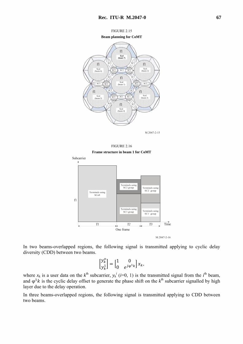
Rec. ITU-R M.2047-0 67
FIGURE 2.15
Beam planning for CoMT
M.2047-2-15
f1
Scal(beam 7)
Scal(beam 2)
Scal(beam 1)
Scal(beam 7)
Scal(beam 3)
Scal(beam 4)
Scal(beam 5)
Scal(beam 6)
SC3SC3
SC3 SC3
SC3SC3
SC2 SC2
SC2
SC2
SC2 SC1SC1
SC1SC1
SC2
SC1
SC1
f1
f1 f1
f1
f1
f1
FIGURE 2.16
Frame structure in beam 1 for CoMT
M.2047-2-16
T2
Subcarrier
T1 T3
Terminals usingSC1 group
Terminals usingSC2 group
Terminals usingSC1´ group
Terminals usingSC2´ group
Time
Terminals usingSCall
f1
One frame
In two beams-overlapped regions, the following signal is transmitted applying to cyclic delay diversity (CDD) between two beams.
= 1 00 ,
where xk is a user data on the kth subcarrier, yki (i=0, 1) is the transmitted signal from the ith beam,
and φ is the cyclic delay offset to generate the phase shift on the kth subcarrier signalled by high layer due to the delay operation.
In three beams-overlapped regions, the following signal is transmitted applying to CDD between two beams.

68 Rec. ITU-R M.2047-0
= 1 0 00 00 0
where xk is a user data on the kth subcarrier, yki(i=0, 1, 2) is the transmitted signal from the ith beam,
and φ and φ are the phase shifts on the kth subcarrier signalled by high layer due to the delay operation. The satellite RAN determines an appropriate cyclic delay offset per each beam and the determined cyclic delay offset is applied to the transmission signal of each beam.
2.4.6.4 Cooperative transmission between a satellite and CGCs
This scheme is used for performance enhancement in an integrated satellite/CGC configuration. It can also be applied without any modification of LTE chipset in normal mode because it is implementation specific on the transmitters of satellite and CGCs.
Figure 2.17(a) shows the concept of a system model where a cooperative diversity technique using a space-time coding (STC) scheme is employed, while Fig. 2.17(b) shows an STC-encoded signal transmission to a user terminal equipped with an STC decoder. The STC scheme employed here is called the Alamouti scheme. The satellite transmits data to the UEs and all ground components. In order to achieve diversity gains via utilization of the STC schemes, each of the alternate CGC must transform the received signals into a given encoded signal format, and retransmit them to the UE. The ground components and satellite can cooperate to transmit space-time coded signals, and the ground components can encode signals rather than serving as simple amplifiers. An UE can receive the STC-encoded signals. If the UE receives multiple signals from both repeaters and the satellite, then it can achieve STC gains using these signals.
In addition, a delay compensation algorithm is required. Since the processing delay to transform a given STC-encoded format at the ground component as well as the time difference of propagation delay between the links from the satellite and ground components can be estimated, the delay compensation for the signal paths of the ground components can achieve successful synchronization at the UE. For example, as shown in Fig. 2.17, a coarse and fine compensation can be made at the satellite gateway and each ground component, respectively.

Rec. ITU-R M.2047-0 69
FIGURE 2.17
An example of system model using cooperative diversity technique for an integrated system
M.2047-2-17
Satellite
CGC 1
CGC 2(STC encoder)
User terminal(STC decoder)
Satellite gateway
Cooperative diversityModulation
Pt/3
Coarse delaycompensation
CGC
Fine delaycompensation
Freq.conversion
[ ]x x1 2,
[ ]x x2 1, hR1
[]
x x21
, h
s
[]
xx
12
∗∗
, – hR2Pt/3
Pt/3
(a) system concept
[ ]x x1 2,
STC conversion
[x x x x1 2 1 2, , –]→ [ ]∗ ∗
[ ]x x1 2,
b) STC encoded signal transmission to a user terminal equipped with STC decoder
First, the modulated symbol sequence [x1, x2] is transmitted during the two symbol period 2T. Then, the satellite passes this symbol sequence [x1, x2] during the period 2T. By using a suitable delay compensation algorithm for the signal to the terrestrial repeater, the signal re-transmitted from the repeater can arrive at the user terminal at almost the same time as the one transmitted directly from the satellite.
After receiving the error-free symbol sequence [x1, x2] from the satellite, each alternative CGC applies Alamouti encoding. The following encoding matrix X2 is used to generate the symbol sequences transmitted by the two repeaters.
−=*12
*21
2xx
xxX ,
where * represents a complex conjugate operation.
In the encoding matrix of an STC scheme, each row of the matrix represents time slots, and the columns represent the corresponding transmit antennas. Therefore, the encoding matrix, X2 indicates that the first CGC transmits the signal set [x1, x2], whereas the second one transmits [–x2
*, x1*], during the period 2T. By this means, a user terminal can achieve diversity gains via a
combination of both signal paths from the satellite and repeaters, wherever possible.
A user terminal can receive various combinations of signal sets depending on the signal availability, which mainly depends on the location. If the user terminal receives three signal sets, i.e. [x1, x2] from the satellite with channel gain hs, [x1, x2] from one of the repeaters with a channel gain of hR1, and [–x2
*, x1*] from the other repeater with a channel gain of hR2, then it can achieve maximal
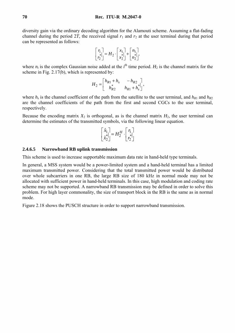
70 Rec. ITU-R M.2047-0
diversity gain via the ordinary decoding algorithm for the Alamouti scheme. Assuming a flat-fading channel during the period 2T, the received signal r1 and r2 at the user terminal during that period can be represented as follows:
,*2
1*2
12*
2
1
+
⋅=
n
n
x
xH
r
r
where ni is the complex Gaussian noise added at the ith time period. H2 is the channel matrix for the scheme in Fig. 2.17(b), which is represented by:
+
−+= *
1*
2
212
sRR
RsR
hhh
hhhH ,
where hs is the channel coefficient of the path from the satellite to the user terminal, and hR1 and hR2 are the channel coefficients of the path from the first and second CGCs to the user terminal, respectively.
Because the encoding matrix X2 is orthogonal, as is the channel matrix H2, the user terminal can determine the estimates of the transmitted symbols, via the following linear equation.
⋅=
*2
12*
2
1
ˆ
ˆ
r
rH
x
x H
2.4.6.5 Narrowband RB uplink transmission
This scheme is used to increase supportable maximum data rate in hand-held type terminals.
In general, a MSS system would be a power-limited system and a hand-held terminal has a limited maximum transmitted power. Considering that the total transmitted power would be distributed over whole subcarriers in one RB, the large RB size of 180 kHz in normal mode may not be allocated with sufficient power in hand-held terminals. In this case, high modulation and coding rate scheme may not be supported. A narrowband RB transmission may be defined in order to solve this problem. For high layer commonality, the size of transport block in the RB is the same as in normal mode.
Figure 2.18 shows the PUSCH structure in order to support narrowband transmission.

Rec. ITU-R M.2047-0 71
FIGURE 2.18
Uplink PUSCH channel structure for narrow-band transmission
M.2047-2-18
180
kH
z
90 k
Hz
45 k
Hz
30
kHz
PUSCH NB format 1
Even numbered slots
One TTI
Odd numbered slots
One subframe = 1 ms
PUSCH NB format 3
a)
Even numbered slots
One TTI
Odd numbered slots
One subframe = 1 ms
Even numbered slots Odd numbered slots
One subframe = 1 ms
PUSCH NB format 2
Even numbered slots
One TTI
Odd numbered slots
One subframe = 1 ms
Even numbered slots Odd numbered slots
One subframe = 1 ms
Even numbered slots Odd numbered slotsOdd numbered slotsEven numbered slots
One subframe = 1 ms One subframe = 1 ms
PUSCH NB format 4
b)
c)
Odd numbered slots
One TTI
Even numbered slots
One subframe = 1 ms
Odd numbered slots Even numbered slots
One subframe = 1 ms
Odd numbered slots Even numbered slotsEven numbered slotsOdd numbered slots
One subframe = 1 ms One subframe = 1 ms
Even numbered slots
One subframe = 1 ms
d)
RS2
RS1
RS1
RS1
RS2
RS2
RS1
RS1
RS1
RS1
RS2
RS2
RS2
RS2
RS2
RS2
RS2
RS2
RS1
RS1
RS1
RS1
RS1
RS2
Odd numbered slots
Figure 2.18(a) shows the normal mode PUSCH structure with the large RB size of 180 kHz, which has 12 subcarriers and 2 slots. The information bits are first channel-coded with a turbo code of mother code rate with 1/3, which is adapted to a suitable final code rate by a rate-matching process. This is followed by symbol-level channel interleaving, which follows a simple “time-first” mapping – in other words, adjacent data symbols end up being mapped first to adjacent SC-FDMA symbols in the time domain, and then across the subcarriers. The coded and interleaved bits are then scrambled by a length-31 Gold code prior to modulation mapping, DFT-spreading, subcarrier mapping and OFDM modulation. For channel estimation and data demodulation, reference signals (RSs) 1 and 2 are transmitted in each even-numbered and odd-numbered slots of a TTI, respectively.
Figure 2.18(b) shows the narrowband PUSCH structure with the RB size of 90 kHz, which has 6 subcarriers and 4 slots. Its channel bandwidth is decreased to the half and TTI is increased to twice, compared to those of the conventional PUSCH. A simple “time-first” mapping is also made for efficient transmission in power-limited satellite uplink. Within one TTI, adjacent data symbols are mapped first to adjacent SC-FDMA symbols in the time domain, and then across the subcarriers. On the other hand, in order to reuse the conventional RSs 1 and 2 in narrowband PUSCH and get a time diversity gain, the first half of RSs 1 and 2 are transmitted in the first and second slots, respectively, and then the rest half of RSs 1 and 2 are mapped in the third and fourth slots, respectively.
In a similar way to Fig. 2.18(b), Figs 2.18(c) and (d) also show the proposed narrowband PUSCH structure with the RB sizes of 45 and 30 kHz, respectively. The number of subcarriers in the narrowband PUSCHs is limited to products of 2, 3 and 5 for commonality with terrestrial LTE because DFT size in terrestrial LTE is limited to those for low complexity of DFT implementation.

72 Rec. ITU-R M.2047-0
When satellite RAN delivers uplink resource allocation information to an UE, it shall include uplink PUSCH format information via the following format indicators.
– if PUSCH with the RB size of 180 kHz is used, the format indicator “00” is sent by satellite RAN;
– if PUSCH with the RB size of 90 kHz is used, the format indicator “01” is sent by satellite RAN;
– if PUSCH with the RB size of 45 kHz is used, the format indicator “10” is sent by satellite RAN;
– if PUSCH with the RB size of 30 kHz is used, the format indicator “11” is sent by satellite RAN.
Because the normal mode is operated with 180 kHz size of RB, narrowband PUSCHs shall be grouped with 180 kHz bandwidth size within one TTI in order to be compatible with normal mode as well as terrestrial LTE.
In the same principle, PUCCH structure is shown in Fig. 2.19. PUCCH is used by a UE to transmit any necessary control signalling only in subframes, in which the UE has not been allocated any RBs for PUSCH transmission. The control signalling on the PUCCH is transmitted in a frequency region on the edges of the system bandwidth. In order to minimize the resource needed for transmission of control signalling in one subframe, each PUCCH transmission in one subframe is comprised of a single RB at or near one edge of the system bandwidth, followed by a second RB at or near the opposite edge of the system bandwidth, as shown in Fig. 2.19. Similarly to PUCCH structure, Figs 2.19(a) and 2.19(b) represent the normal mode PUCCH formats 1 and 2 and their narrowband transmissions for adaptation to satellite uplink. Figure 2.19(b) shows the narrowband PUCCH structure with the RB size of 90 kHz, which has 6 subcarriers and 4 slots. Other narrowband PUCCH structures can be applied in a similar way to Figs 2.18(c) and 2.18(d) for narrowband PUSCH structures.
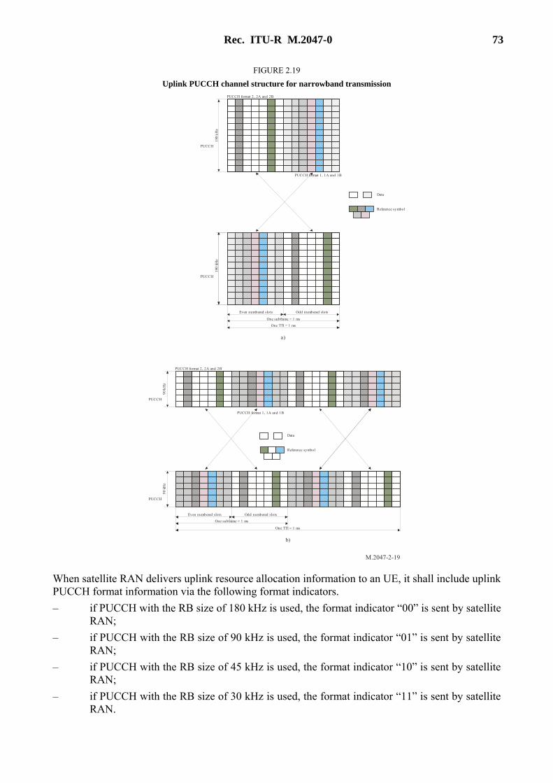
Rec. ITU-R M.2047-0 73
FIGURE 2.19
Uplink PUCCH channel structure for narrowband transmission
M.2047-2-19
180
kH
z
PUCCH format 2, 2A and 2B
Data
a)
Even numbered slots
One TTI = 1 ms
One subframe = 1 ms
PUCCH
PUCCH format 1, 1A and 1B
Reference symbol
180
kH
z
PUCCH
Odd numbered slots
Even numbered slots Odd numbered slots
One subframe = 1 ms
One TTI = 1 ms
90
kH
z
PUCCH
90
kHz
PUCCH
PUCCH format 2, 2A and 2B
Data
Reference symbol
b)
PUCCH format 1, 1A and 1B
When satellite RAN delivers uplink resource allocation information to an UE, it shall include uplink PUCCH format information via the following format indicators.
– if PUCCH with the RB size of 180 kHz is used, the format indicator “00” is sent by satellite RAN;
– if PUCCH with the RB size of 90 kHz is used, the format indicator “01” is sent by satellite RAN;
– if PUCCH with the RB size of 45 kHz is used, the format indicator “10” is sent by satellite RAN;
– if PUCCH with the RB size of 30 kHz is used, the format indicator “11” is sent by satellite RAN.

74 Rec. ITU-R M.2047-0
Because the normal mode is operated with 180 kHz size of RB, narrowband PUCCHs shall be grouped with 180 kHz bandwidth size within one TTI in order to be compatible with normal mode as well as terrestrial LTE. In addition, multiplexing narrowband PUCCH with normal mode PUCCH can be considered in order to reduce the resources used for PUCCH transmission.
2.4.6.6 Downlink transmission scheme with low PAPR
This scheme is used to reduce peak to average power ratio (PAPR) in downlink transmission of the enhancing mode. Because SAT-OFDM downlink shall support both normal and enhancing mode UEs in downlink frame, only MBSFN subframes indicated to normal mode UE are used as subframes to transmit signals of enhancing mode UEs. For compatible operation with normal mode UEs, multiplexing enhancing mode UEs with normal mode UEs within one radio frame is achieved according to the flow in Fig. 2.20.
FIGURE 2.20
Downlink OFDMA transmission combined with SC-FDM
M.2047-2-20
Allocation of the normal mode UEs in the framestructure in commonality with the 3GPP LTE
Calculate capacities required for normal mode UEs
Decision on the number of MBSFN subframesaccording to capacity required for accessed normal
mode UEs
Identification of the subframes No. for MBSFN except the subframes No. 0, 4, 5, 9
Transmission of the information on MBSFNsubframes to UEs via PBCH
End
Check if the enhancing UEs exist in thesystem
Acquisition of system information (SI) into UEs
Normal mode operation in the subframes exceptMBSFN subframes
Enhancing mode operation in the MBSFNsubframes
Check if MBSFN subframes are existing
End
Check if MBSFN subframes are consideredfor the enhancing mode UEs
Normal mode operation for MBMS
Check if only subframes 0.5 can beconfigured as MBSFN subframes
Identification of the subframes No. for MBSFN exceptthe subframes No. 0, 5
Transmission of the information on MBSFNsubframes to UEs via PBCH
Acquisition of SI into UEs
Normal mode operation in the subframes exceptMBSFN subframes
Check if MBSFN subframes are existing
Check if MBSFN subframes are consideredfor the enhancing mode UEs
Normal mode operation
Decision on the number of MBSFN subframesaccording to capacity required for accessed normal
mode UEs
Start
End
End
Enhancing mode operation in the MBSFNsubframes
Normal mode operation for MBMS
End
End
Normal mode operation
End
Normal mode operation
Figure 2.21 shows an example of frame structure for downlink transmission with low PAPR in enhancing mode UEs. The subframes 0, 4, 5, and 9 shall be used for normal mode UEs and other subframes can be used for enhancing mode UEs. The normal mode UE recognizes the subframes for enhancing mode UEs as MBSFN subframes. System information (SI) on which subframes are used for enhancing mode (or MBSFN) is transmitted to UEs via PBCH. The first one or two symbols of MBSFN subframes shall be used for PDCCH for normal mode UEs but the normal

Rec. ITU-R M.2047-0 75
mode UEs do not receive data on the other symbols of MBSFN subframes. Therefore, the other symbols of MBSFN subframes can be used for single carrier transmission with low PAPR for performance enhancement of enhancing mode UEs from non-linearity of power amplifier in satellite. Satellite RAN controls that the subframes 4 and 9 are not used for paging, and then they can also be allocated to enhancing mode UEs.
FIGURE 2.21
Frame structure for downlink transmission with low PAPR
M.2047-2-21
Normal modeUEs
Control signal for the normal mode UEs
OFDMAtransmission
Subframe 0
Enhancing modeUEs
Subframe 1
Enhancing modeUEs
Subframe 2
Enhancing modeUEs
Subframe 3
Normal modeUEs
Subframe 4
NormalmodeUEs
Subframe 5
Enhancing modeUEs
Subframe 6
Enhancing modeUEs
Subframe 7
Normal modeUEs
Subframe 9
Enhancing modeUEs
Subframe 8
SC-FDMAtransmission
SC-FDMAtransmission
SC-FDMAtransmission
OFDMAtransmission
SC-FDMAtransmission
SC-FDMAtransmission
SC-FDMAtransmission
OFDMAtransmission
OFDMAtransmission
OFDMAtransmission
Reference signal for the normal mode UEs
Reference signal for the enhancing mode UEs
OFDMAtransmission
OFDMAtransmission
Generation of an SC-FDM signal for enhancing mode UEs in the frequency domain uses a Discrete Fourier Transform-Spread OFDM (DFT-S-OFDM) structure, as shown in Fig. 2.22.
FIGURE 2.22
Downlink transmission block with low PAPR
M.2047-2-22
ScramblingModulation
mapperRE
mapper
Precoding
Z-pointDFT
spreading
Layers
Add cyclicprefix
Parallel toserial
converter
Antennaports
ScramblingModulation
mapperRE
mapper
RSmapper
RSmapper
Z-pointDFT
spreading
N-pointDFT
spreading
N-pointDFT
spreading
Add cyclicprefix
Parallel toserial
converter
RE mapping for data symbol and RS mapping for RS symbol apply to the same rule for normal mode operation. The size of Z-point DFT depends on the number of subcarriers which are used for data and RS symbol. The RBs for UEs shall be continuously mapped in order to keep single carrier property.

76 Rec. ITU-R M.2047-0
2.4.6.7 Efficient AMC scheme combined with power control
A channel quality indicator (CQI) structure in normal mode is changed for the AMC scheme combined with power control. Five bits are allocated in the normal mode to identify 32 MCS modes. But in enhancing mode, five bits are divided into two parts: the first n bits are allocated to identify MCS modes, and the other (5-n) bits are allocated for power control where the parameter, n is signalled by high layer. When (5-n) bits are used for power control, 2(5-n) different power control steps are defined using (5-n) bits. If the reported channel state (RCS) at t corresponds to the kth power level, a UE sends the message to transmit in the 2(5-n)th power level. After satellite RAN receives a CQI showing that the receive power level was at the kth level, the transmitting power level is adjusted as follows:
Transmit_Power(t) = Transmit_Power (t−1) + (25-n – k) · β
where β is a power difference between ith and (i+1)th power control steps.
FIGURE 2.23
AMC scheme combined with power control
M.2047-2-23
···2
5- n321
ΔRSth
RCS at t, RS(t)
dBβ
Operating range of MCS i
RSth( )i RSth( +1)i
In Fig. 2.23, RSth(i) and ΔRSth represent the lower bound of channel state at MCS mode i and the lower bound difference of channel states at MCS modes i and (i+1), respectively.
The procedures of AMC scheme combined with power control are as follows:
– removing a power control level, applied to a previously-received packet, from the calculated received SNR, i.e. substracting the power controlled level in dB from the calculated received SNR in dB;
– using the above subtracted SNR as a final received SNR;
– deciding an MCS mode based on the final received SNR and determining whether power control is required:
i) when the power control is determined to be required, deciding a required power control magnitude using a channel state positioned in a corresponding MCS mode range (in Fig. 2.23, when the RCS location is 25-n, the power control is not required);
– transmitting the decided MCS mode and a power control information of the decided power control magnitude through the channel quality indicator (CQI) feedback or the MCS information.
2.4.6.8 HARQ/ARQ interaction
In normal mode, each of the HARQ and ARQ independently performs an assigned task in a corresponding layer. In enhancing mode, the HARQ and ARQ interactively perform for improving transmission efficiency, by interacting between an HARQ operation performed in a MAC layer or a physical layer and an ARQ operation performed in a radio link control (RLC) layer. Feedback information received from the HARQ is reported to the ARQ layer; this enables the ARQ to

Rec. ITU-R M.2047-0 77
perform prompt retransmission and to cope with an HARQ feedback error. Accordingly, the transmission efficiency can be improved.
The transmission window is operated according to the HARQ feedback information and the waiting window is operated according to the status PDU. The transmission window is operated based on the VT(A), VT(S), and VT(MS) of the RLC transmission window, and the waiting window is operated based on the VT(CA).
The transmission window is operated in the manner described in normal mode. In enhancing mode, only an operation scheme of the VT(A) is modified according to the HARQ feedback information. In normal mode, the VT(A) is updated based on a received positive acknowledgment signal, namely ACK of the status PDU. On the other hand, in enhancing mode, the VT(A) is updated based on inner feedback information with respect to reception of ACK of HARQ.
In enhancing mode, the VT(CA) of the waiting window is updated based on an ACK in the status PDU. In case of separately managing the transmission window and the waiting window, the transmission window is operated according to inner ACK information from the HARQ, thereby promptly transmitting a subsequent protocol data unit (PDU). When a packet is retransmitted with HARQ and NACK is received from the status PDU, the packet is excluded in the retransmission list of ARQ, thereby preventing unnecessary retransmission.
The VT(CA) has the SN value of a subsequent data packet for which an ACK is to be received via the status PDU according to a sequence, and is provided to the waiting window, as a lower value.
FIGURE 2.24
Window structure for HARQ/ARQ interaction
M.2047-2-24
Transmission Window(operated by feedback from HARQ)
Waiting Window(operated by status PDU
or HARQ/ARQ interaction)
VT(CA) VT(A) VT(S) VT(MS)
MAC determines whether a packet transmission of HARQ succeeds or fails, using the feedback information received in response to the packet transmission. RLC transfers a packet from a transmission window to a waiting window, when the MAC determines that the packet transmission of HARQ succeeds. On the other hand, RLC transfers the packet from the transmission window to a transmission buffer to retransmit the packet, when MAC determines that the packet transmission of HARQ fails after the maximum retransmission. RLC receives the feedback information of status PDU, and determines a process of the retransmitted packet based on the feedback information. RLC deletes the packet, when the packet transmission succeeds as a result of analysis of the status PDU. RLC does not perform retransmission of the packet when MAC is performing retransmission of the packet, when the packet transmission fails and when the packet exists in the transmission window as a result of the status PDU. RLC performs retransmission of the packet when MAC is not performing retransmission of the packet, when the packet transmission fails, and when the packet exists in the waiting window as a result of the status PDU.
2.4.6.9 Modified RBG group size for resource allocation
In normal mode, the size of resource block group (RBG) is determined according to system bandwidth as in Table 2.16. On the other hand, in enhancing mode the maximum size of RBG is

78 Rec. ITU-R M.2047-0
additionally defined according to a UE type and a satellite specification of S-eNodeB as shown in Table 2.17. In Table 2.17, it is considered that the maximum antenna gain of S-eNodeB is 50 dBi and the antenna beam pattern of Recommendation ITU-R S.672-4 is used. If the satellite antenna gain of S-eNodeB or the antenna beam pattern is changed, RBG size according to the UE type may be adjusted. In order to support smaller size of RBG in handheld type over wide system bandwidth, the size of RBG is determined in enhancing mode as follows:
RBG_Size = min (the size of RBG from system bandwidth, Maximum size of RBG from UE type)
TABLE 2.16
The size of RBG from system bandwidth
System bandwidth (the number of RBs)
The size of RBG (the number of RBs)
10 or less 1
11-26 2
27-63 3
64-110 4
TABLE 2.17
The size of RBG from UE type
UE type The size of RBG
(the number of RBs)
Handheld class 1, 2, 3 1
Portable 2
Vehicular, Transportable 4
2.4.6.10 Definition of a new receiver memory field for HARQ
A direct implementation of the HARQ scheme into a satellite system will cause a serious memory problem at the receiver, due to the long RTD of a satellite communication system. For compatible operation with 8-channel HARQ, the receiver requires a large amount of memories for continuous transmission, in order to manage erroneous packets. In enhancing mode of the SAT-OFDM, the receiver memory (RM) field is added in order to solve the above problem. The RM field is inserted into HARQ feedback packet for the continuous transmission.
The RM field in Fig. 2.25 indicates the status of the receiver memory. The interpretation of the RM field is provided in Table 2.18.
FIGURE 2.25
Additional RM field inserted in HARQ feedback packet
M.2047-2-25
HARQ Feedback (ACK/NACK)
RM field(2 bits)

Rec. ITU-R M.2047-0 79
TABLE 2.18
RM field interpretation
Value Description
00 Receiver memory is enough to store new erroneous packet.
01 Receiver memory is not enough to store new erroneous packet.
10 The packet indicated by feedback information was not stored in receiver memory.
11 The packet indicated by feedback information should be retransmitted in the first piece of encoding packet.
When a UE receives a MAC PDU, the UE decides a value of RM field according to a state of the receiver memory, and the UE sends a feedback packet with RM field.
2.4.6.11 Buffer status reporting for satellite communication
The buffer status reporting (BSR) scheme may not be supported in the satellite system due to long RTD. In a satellite system, buffer status information from a UE is not valid after a long RTD, because the buffer status can be greatly changed during the RTD. Therefore, uplink scheduling cannot be performed on the basis of buffer status information of a UE.
The BSR of a UE in the enhancing mode of the SAT-OFDM is performed in two modes; a normal reporting operation or a successive reporting operation. In the normal reporting operation, entire buffer status information of the UE is reported as in the terrestrial LTE. On the other hand, in the successive reporting operation, information on the increased amount of data in the buffer since the last reporting is reported. The increased data amount is a value obtained by adding an amount of data, which is waiting for being re-transmitted through feedback of transmission failure among data which has already been transmitted, to an amount of data which is newly added to the buffer of the user terminal. The normal reporting operation and the successive reporting operation are distinguished by logical channel identifier (LCID) values as in Table 2.19.
TABLE 2.19
Values of LCID for UL-SCH
Index LCID values
00000 Common control channel (CCCH)
00001-01010 Identity of the logical channel
01011-10110 Reserved
10111 Truncated BSR for successive reporting
11000 Short BSR for successive reporting
11001 Long BSR for successive reporting
11010 Power Headroom Report
11011 Control-radio network temporary identifier (C-RNTI)
11100 Truncated BSR

80 Rec. ITU-R M.2047-0
2.4.6.12 HARQ retransmission in satellite carrier aggregation
In case of enhancing mode operation, the component carriers are changed for the HARQ retransmission. This can be used to reduce upper layer delay. When different feedback packets are received from component carriers, and the gain from the change of component carriers is larger than that of a HARQ retransmission without the change of component carriers, the transmitter changes component carriers for a HARQ. The gain from the change of the component carriers can be obtained if the channel condition improves due to the change of the component carriers, and the previous MCS mode is applied, and subsequently the BLER performance improves. When the transmitter changes the component carrier for the retransmission, the initial version of HARQ packet is transmitted in a new component carrier and a new data packet is transmitted in the previous component carrier. For discriminating the component carrier change, NDI field is modified as in Table 2.20.
TABLE 2.20
NDI field interpretation
Value Description
00 New data packet
01 Retransmitted packet
10 New data packet with changing component carrier
11 Reserved
Basically, the NDI field (value: 00 and 01) is used the same in normal mode operation. When an event of the component carrier change is occurred, the transmitter, which received a negative acknowledgement, sends a new packet with the newly defined NDI field (value: 10).
The steps of the HARQ retransmission in carrier aggregation are as follows:
– receiving different feedback packets from component carriers;
– comparing the gain of the component carrier change with the average gain of HARQ retransmission:
i) when three or more component carriers are used, the priority according to the sequence number of the upper layer packet and the channel condition is applied to the component carrier change;
– applying the component carrier change, when the gain of the component carrier change is larger than that of HARQ retransmission:
i) an initial version packet of HARQ is transmitted at the component carrier where a packet error is not occurred;
ii) a new packet is transmitted at the component carrier where a packet error is occurred;
– not applying the component carrier change, when the average gain of HARQ retransmission is larger than that of the component carrier change:
i) the continued operation is the same in the normal operation.

Rec. ITU-R M.2047-0 81
2.5 Detailed specifications
Since SAT-OFDM is derived from 3GPP LTE(-Advanced), the organization of the SAT-OFDM specifications closely follows the original 3GPP structure. The SAT-OFDM numbers have been designed to follow the corresponding 3GPP LTE numbering system. All SAT-OFDM specifications have the following numbering system.
– SAT-OFDM xx.yyy
where the numbers xx and yyy correspond to the 3GPP-numbering scheme.
Due to the differences between terrestrial and satellite channel characteristics, some modifications to the LTE standards are necessary. Some specifications are directly applicable, whereas others are applicable with modifications.
A SAT-OFDM system is defined by the combination of a family of SAT-OFDM specifications and 3GPP specifications, as follows:
– If a SAT-OFDM specification exists it takes precedence over the corresponding 3GPP specification (if any). This precedence rule applies to any references in the corresponding 3GPP specifications.
– If a SAT-OFDM specification does not exist, the corresponding 3GPP specification may or may not apply.
The detailed specifications for SAT-OFDM radio interface is based on the following set of documents:
– Physical layer: the most recent version of the SAT-OFDM documents derived from the 36.200 series.
– Protocols: the most recent version of the SAT-OFDM documents derived from the 36.300 series.
This set of detailed specifications in SAT-OFDM Release 1 is presently being elaborated based on 3GPP LTE Release 8 specifications inside the Radio Access Working Group (WG7011) under IMT-Advanced Project Group (PG701) of TTA in Korea (Republic of).