detecting file fragmentation point using sequential
TRANSCRIPT
DIGITAL FORENSIC RESEARCH CONFERENCE
Detecting File Fragmentation Point Using Sequential
Hypothesis Testing
By
Anandabrata Pal, Husrev Sencar, Nasir Memon
From the proceedings of
The Digital Forensic Research Conference
DFRWS 2008 USA
Baltimore, MD (Aug 11th - 13th)
DFRWS is dedicated to the sharing of knowledge and ideas about digital forensics
research. Ever since it organized the first open workshop devoted to digital forensics
in 2001, DFRWS continues to bring academics and practitioners together in an
informal environment.
As a non-profit, volunteer organization, DFRWS sponsors technical working groups,
annual conferences and challenges to help drive the direction of research and
development.
http:/dfrws.org
Detecting file fragmentation point using sequentialhypothesis testing
Anandabrata Pal*, Husrev T. Sencar, Nasir Memon
Computer Science Department, Polytechnic University, 6 Metrotech Center, Brooklyn, NY 11201, United States
Keywords:
File carving
Data recovery
Forensics
Fragmentation, Sequential
hypothesis testing
DFRWS carving challenge
a b s t r a c t
File carving is a technique whereby data files are extracted from a digital device without
the assistance of file tables or other disk meta-data. One of the primary challenges in file
carving can be found in attempting to recover files that are fragmented. In this paper,
we show how detecting the point of fragmentation of a file can benefit fragmented file
recovery. We then present a sequential hypothesis testing procedure to identify the frag-
mentation point of a file by sequentially comparing adjacent pairs of blocks from the start-
ing block of a file until the fragmentation point is reached. By utilizing serial analysis we
are able to minimize the errors in detecting the fragmentation points. The performance
results obtained from the fragmented test-sets of DFRWS 2006 and 2007 show that the
method can be effectively used in recovery of fragmented files.
ª 2008 Digital Forensic Research Workshop. Published by Elsevier Ltd. All rights reserved.
1. Introduction
With the ever increasing adoption of digital storage mediumsfor both legitimate and criminal use, the need for moresophisticated data recovery and forensic recovery products
has also increased. Most file systems and storage devices storedata by dividing it into many clusters and by maintaining thelist of clusters (file table) used for storing each file’s data.1
When a file is accessed the data is retrieved in sequencefrom this list of clusters. Similarly, deletion of a file is typicallyrealized by removing a file’s entry from the file table. Tradi-tional data recovery and forensics products attempt to recoverdata by analyzing the file system and extracting the datapointed to by the file system. Traditional recovery techniquesfail to recover data when the file system is corrupted, not pres-ent or has missing entries. File carving was then introduced torecover files from the ‘‘unallocated’’ space of a disk, i.e., the
area of the disk not pointed to by the file system. The initialand still by far most common form of file carvers simply
analyze headers and footers of a file and attempt to mergeall the blocks in between. One of the most well known of thesefile carvers is Scalpel (Richard and Roussev, 2005). However,these file carvers still fail to recover files that are fragmented.
A file is said to be fragmented when it is not stored on a con-
tinuum of clusters, and the most difficult challenge in datacarving is to recover files when they are fragmented into twoor more pieces. Garfinkel (2007) determined that fragmenta-tion on a typical disk is less than 10%, however, the fragmen-tation level of forensically important file types (like images,office files, and email) is relatively high. Among his main find-ings are that up to 42% of PST files (outlook email) 17% of MS-Word files and 16% of JPEGs are fragmented. It is, therefore,clear that recovery of fragmented files is a critical problemin forensics.
While the starting and end points of a file can be identifiedby specific markers (e.g., file headers and footers), the point at
which a file fragments and the point at which the next frag-ment starts can be extremely difficult to ascertain. Identifying
* Corresponding author. Tel.: þ1 917 482 0211.E-mail address: [email protected] (A. Pal).
1 For example, in the file system FAT-32 the root table entry with the file name will point to the first cluster of the file, which in turn willpoint to the next cluster and so on until the last cluster of the file.
ava i lab le a t www.sc iencedi rec t .com
journa l homepage : www.e lsev ie r . com/ loca te /d i in
1742-2876/$ – see front matter ª 2008 Digital Forensic Research Workshop. Published by Elsevier Ltd. All rights reserved.doi:10.1016/j.diin.2008.05.015
d i g i t a l i n v e s t i g a t i o n 5 ( 2 0 0 8 ) S 2 – S 1 3

these points involves a detailed understanding of individual
file formats, and existing techniques fail to scale when dealingwith hundreds of thousands of blocks, and files that may befragmented into more than two fragments.
In this paper, we show how by identifying the fragmenta-tion point of a file we can improve the performance of Garfin-kel’s (2007) bifragment gap carving technique, as well as Paland Memon’s (2006) Parallel Unique Path (PUP) techniquesfor recovering fragmented files. We present a technique toidentify the fragmentation point(s) of a file by utilizingsequential hypothesis test (SHT) procedure. The techniquebegins with a header block identifying the start of a file and
then attempts to validate via SHT each subsequent block fol-lowing the header block. The fragmentation point is identifiedwhen SHT identifies a block as not belonging to the file. By uti-lizing this technique, we are able to correctly and efficientlyrecover JPEG images from the DFRWS 2006 (Carrier et al.,2006) and 2007 (Carrier et al., 2007) test-sets even in the pres-ence of tens of thousands of blocks and files fragmented intothree or more parts. The bifragment gap carving techniqueenhanced with SHT allows us to improve the performanceresult of DFRWS 2006 challenge test-sets, although the tech-nique cannot be used for DFRWS 2007. We then show how Par-
allel Unique Path enhanced with SHT is able to recover allfragmented JPEGs from DFRWS 2006 and all recoverable JPEGsfrom 2007 challenge test-sets. As far as we are aware, no otherautomated technique can recover multi-fragmented JPEGsfrom the DFRWS 2007 test set.
The next section begins with a description of fragmenta-tion and how fragmentation occurs on disks. We then definethe basic terms used throughout the paper. Section 3describes existing techniques for fragmented file recovery,followed by Section 4 which describes our technique for frag-mentation point detection. We then formalize the fragmenta-
tion point detection problem and describe our solution inSection 5. Section 6 contains information about our refinedfile carving system using Fragmentation Point Detection basedon the PUP carver. We detail our experiments and results inSection 7 for the new file carver as well as bifragment gapcarving. We conclude with some open problems as well asareas that we are currently looking into.
2. Fragmentation
File fragmentation is said to occur when a file is not stored inthe correct sequence on consecutive blocks on disk. In otherwords if a file is fragmented, the sequence of blocks fromthe start of a file to the end of the file will result in an incorrectreconstruction of the file. Fig. 1 provides a simplified exampleof a fragmented file. In the figure, the file J1 has been brokeninto two fragments. The first fragment starts at block 1 andends at block 4. The second fragment starts at block 8 andends at block 9. This file is considered to be bi-fragmented
as it has only two fragments. Garfinkel (2007) showed thatbi-fragmented fragmentation is the most common type offragmentation, however, files fragmented into three or morepieces are not uncommon.
Garfinkel’s fragmentation statistics come from identifyingover 350 disks containing FAT, NTFS and UFS file systems.
Fragmentation typically occurs under one of the followingscenarios:
(1) Low disk space: If the disk space is low and the disk is notdefragmented, there may be many small groups ofblocks/clusters that are available for storing information.However, future files to be stored may be larger than the
largest of these free groups of blocks, and as a resulta file may need to be fragmented across multiple of theseblocks.
(2) Appending/editing files: If a file is saved on disk and then ad-ditional files are also saved starting at the cluster that theoriginal file ended at, then fragmentation may occur if theoriginal file is then appended to (and increases in size largerthan the cluster size). Some file systems like the AmigaSmart Filesystem may attempt to move the whole file insuch scenarios. Some other file systems like UFS attemptto provide ‘‘extents’’ which are attempts to pre-allocatelonger chunks in anticipation of appending (McVoy and
Kleiman, 1991). Another technique called delayed alloca-tion used in file systems like XFS (Sweeney et al., 1996)and ZFS reserve file system blocks but attempt to delaythe physical allocation of the blocks until the operating sys-tem forces a flushing of the contents. However, while someof these techniques are able to reduce fragmentation theyare unable to eliminate fragmentation completely.
(3) Wear-leveling algorithms in next generation devices: Solid StateDevices are currently utilizing proprietary wear-levelingalgorithms to store data on the disk (STORAGEsearch.com). If the information mapping the logical geometry of
the disk to the physical geometry is destroyed or gets cor-rupted, then any data extracted will be fragmented, withno easy way of determining the correct sequence of blocksto recover files.
(4) File system: In rare cases the file system itself will forcefragmentation. The Unix File System will fragment filesthat are long or have bytes at the end of the file that willnot fit into an even number of sectors (Carrier, 2005).
In Table 1, we give basic definitions concerning fragmenta-tion that will be used throughout the paper and Fig. 1 provides
a simple visualization of these definitions.As mentioned earlier, once a file has been fragmented, tra-
ditional file carving techniques will fail to recover the file. Inthe next section, we detail the process required to recoverfragmented files and provide a description of existing tech-niques to achieve this.
J1 ? ?J1 J1J1J1 J1?
Header Fragmentation Point
Base-fragment Fragment
641 52 83 97
Blocks
Footer
Fig. 1 – File J1 has been broken into two fragmentsspanning six blocks, with three blocks in between notbelonging to J1.
d i g i t a l i n v e s t i g a t i o n 5 ( 2 0 0 8 ) S 2 – S 1 3 S3
3. Fragmented file carving
To recover fragmented files correctly a file carver must be ableto determine the starting point of a file and the correct blocksthat are required to reconstruct the file. In essence it is a threestep process:
(1) Identify starting point of a file.(2) Identify blocks belonging to file.(3) Order the blocks correctly to reconstruct the file.
There are two published techniques that attempt to followthis three step process in differing ways. We now describethese two techniques.
3.1. Bifragment gap carving
Garfinkel (2007) introduced the fast object validation techniquefor recovery of fragmented files. This technique recovers filesthat have headers and footers and are fragmented into twofragments (bi-fragmented). This technique works only for filesthat can be validated/decoded. Decoding is the process oftransforming information in the data blocks associated witha file into its original format that describes the actual content.
Many file types, like JPEG, MPEG, ZIP, etc., have to be decodedbefore their content can be understood. Object validation isthe process of verifying if a file obeys the structured rules ofits file type. Therefore, an object validator will indicatewhether a block violates the structure or rules required ofthe specific file or file type. For example in the PNG file format,
the data can be validated through cyclic redundancy checking,
and a mismatch will indicate either data corruption or frag-mentation. A decoder can be trivially used as an object valida-tor by observing whether or not it can correctly decode eachblock in the sequence.
Bifragment Gap Carving (BGC) recovery occurs by exhaus-tively searching all combinations of blocks between an identi-fied header and footer while excluding different number ofblocks until a successful decoding/validation is possible. Wenow describe bifragment gap carving in greater detail. Let bh
be the header block, bf be the last block of the first fragmentof a file, bs be the starting block of the second fragment, and
bz be the footer block. Blocks bh and bz are known and bf andbs have to be determined. For each gap size g, starting withsize one, all combinations of bf and bs are designated so thatthey are exactly g blocks apart, i.e., s" f¼ g. A validator/decoder is then run on the byte stream representing blocksbh to bf and bs to bz. If the validation fails bf and bs are read-justed and the process continued until all choices of bf andbs are tried for that gap size, after which the gap size is incre-mented. This continues until a validation returns true or thegap size can’t be increased any further. This technique per-forms satisfactorily when the two fragments are close to
each other; however, it has the following limitations for themore general case.
(1) The technique does not scale for files fragmented withlarge gaps. If n is the number of blocks between bh and bz
then in the worst case n2 object validations may berequired before a successful recovery.
(2) For files with more than two fragments, the number ofobject validations that need to be performed can be im-practically high. This is because n" 1 gap sizes have tobe used in parallel where n is the number of fragments in
the file. It is also very highly unlikely that n can be deter-mined before hand.
(3) Successful decoding/validation does not always imply thata file was reconstructed correctly. Decoders will give anerror when the data in the blocks do not conform to inher-ent decoding rules or structure. For example, standardJPEG decoder will stop with an error when a retrieved bitpattern has no corresponding entry in the Huffman codetable. Fig. 2 from DFRWS 2007 is an example of a success-fully decoded but incorrect JPEG file.
(4) Many file types cannot be validated by their structure or donot require decoding. For example, 24-bit BMPs have
a header, followed by pixel values where each pixel is repre-sented with three bytes, and has no footer. If a bitmap imageis fragmented, any block can be considered to be a candidatefor thefragmentation pointand thestarting point of anotherfragment. Object validation will fail in such a case.
(5) Missing or corrupted blocks for a file will result in the worstcase often.
3.2. Graph theoretic carving
Pal and Memon (2006) formulate the image reassembly prob-lem as a k-vertex disjoint graph problem and reassembly isthen done by finding an optimal ordering of blocks. Their
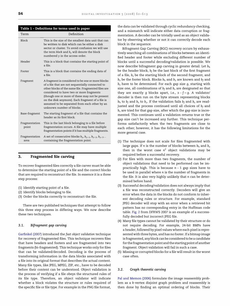
Table 1 – Definitions for terms used in paper
Term Definition
Block This is the size of the smallest data unit that canbe written to disk which can be either a disksector or cluster. To avoid confusion we will usethe term block and by will denote the blocknumbered y in the access order.
Header This is a block that contains the starting point ofa file.
Footer This is a block that contains the ending data ofa file.
Fragment A fragment is considered to be one or more blocksof a file that are not sequentially connected toother blocks of the same file. Fragmented files areconsidered to have two or more fragments(though one or more of these may not be presenton the disk anymore). Each fragment of a file isassumed to be separated from each other by anunknown number of blocks.
Base-fragment The starting fragment of a file that contains theheader as its first block.
Fragmentationpoint
This is the last block belonging to a file beforefragmentation occurs. A file may have multiplefragmentation points if it has multiple fragments.
Fragmentationarea
A set of consecutive blocks by, byþ1, byþ2, byþ3.
containing the fragmentation point.
d i g i t a l i n v e s t i g a t i o n 5 ( 2 0 0 8 ) S 2 – S 1 3S4

technique does not require object validations or decoding, bututilizes a matching metric to indicate the likelihood that
a block follows another. For file types that can’t be validatedbased on their structure (24-bit BMPs), analysis of the actualcontents of each file is required to determine if a block shouldbe paired with another block. However, even if a block can bevalidated the contents of each block are still analyzed andmatching metrics created. Matching metrics differ accordingto the file type. For example in images, the matching metricis generated by analyzing the pixel boundary created by themerging of two blocks.
Utilizing the matching metric, they present three algorithmsusing two heuristics. For the purpose of this paper we describe
the Parallel Unique Path (PUP) algorithm using the greedy heu-ristic as this has the best combination of performance andresults. PUP is a modified Dijkstra’s (1959) single source shortestpath algorithm, used to reassemble multiple files simulta-neously. Starting with the file headers of each file, the bestmatch for each header is chosen and then the header–blockpairwith the best of all thebest matches ismerged to the header.The process is repeated until all files are reconstructed.
More formally, the k file headers (bh1, bh2, . bhk) are storedas the starting blocks in the reconstruction paths Pi for each ofthe k files. A set S¼ (bs1, bs2, . , bsk) of current blocks is main-
tained for processing, where bsi is the current block for the ithfile. Initially, all the k starting header blocks are stored as thecurrent blocks for each file (i.e., bsi¼ bhi). The best greedymatch for each of the k starting blocks is then found andstored in the set T¼ (bt1, bt2, ., btk) where bti represents thebest match for bsi. From the set T of best matches the blockwith the overall best matching metric is chosen.
Assuming that this best block is bti, the following steps areundertaken:
(1) Add bti to reconstruction path of ith file, (i.e., Pi¼ Pikbti).
(2) Replace current block in set S for ith file (i.e., bsi¼ bhi).(3) Evaluate new set T of best matches for S.(4) Again find best block bti in T.(5) Repeat 1 until all files are built.
Fig. 3 shows an example of the algorithm where there are
three files being reconstructed. Fig. 3(a) shows the headerblocks H1, H2 and H3 of the three files and their best matches.The best of all the matches is presented with a dotted line andis the H2–6 pair of blocks. Fig. 3(b) now shows the new set ofbest matches after block 6 has been added to the reconstruc-tion path of H2. Now block 4 is chosen once each for blocksH1 and 6. However, the pair H1–4 is the best and therefore 4is added to the reconstruction path of H1 and the next bestmatch for block 6 is determined Fig. 3(c). This process con-tinues until all files are reconstructed.
While the reported results are very promising, the reas-
sembly requires O(n2) computations, where n is the total num-ber of blocks. Clearly, this system fails to scale when dealingwith tens of thousands and even millions of blocks. The rea-son O(n2) computations are necessary is due to the assump-tion that fragmentation occurs completely randomly andfragment sizes can be as small as a single block. However,since it assumes random fragmentation, it is able to handlefiles fragmented into greater than two fragments. Anotherproblem with this technique is that it assumes all blocks arepresent and that there are no holes.
3.3. The need for fragmentation point detection
As mentioned both BGC and PUP have problems when dealingwith fragmented files. Both require O(n2) computations in theworst case and fail to scale for very large gaps or a file frag-mented into many pieces. PUP assumes that fragmentation iscompletely random, however, as shown in Garfinkel (2007),
files with greater than three fragments are very rare, and filesystems will almost never fragment a file on a block by blockbasis. BGC assumes if a file validates it is correct, and doesnot attempt to validate or score individual pairs of blocks.
Fig. 2 – Fully validated but incorrect JPEG image from theDFRWS 2007 test set.
Fig. 3 – Simplified example of PUP algorithm.
d i g i t a l i n v e s t i g a t i o n 5 ( 2 0 0 8 ) S 2 – S 1 3 S5

Both techniques would benefit from being able to identify
the base-fragment, which as defined earlier, is the first frag-ment of a file. More specifically, the last block of the base-fragment (i.e., fragmentation point) needs to be detected.In the case of BGC, correct fragmentation point identificationallows the assumed fragmentation ending point bf (as de-fined earlier) to be fixed, and only bs (next fragment startingpoint) adjusted, thus greatly reducing the number of compu-tations required to validate a file. Even if the fragmentationpoint was not found, but the fragmentation area was found(a small set of blocks, one of which contains the fragmenta-tion point), bf would only need to be adjusted within the
fragmentation area and not from the header. In the case ofPUP rather than assuming each block is randomly frag-mented, a modification can be made so that if a block is cho-sen to belong to a file, then the blocks following the chosenone are sequentially compared to the previous block, untila fragmentation point is reached, at which point the algo-rithm will resume as normal. In the next section we presentsome simple techniques that can be used for fragmentationpoint detection.
4. Fragmentation point detection
In Fig. 4, a JPEG image J1 has one file fragmentation point at thefourth block, b4. This implies that blocks 1–4 all belongtogether in order. If a file is fragmented into more than twopieces, then multiple file fragmentation points will exist,
and if the file has no fragmentation then there will be no filefragmentation points. For a file fragmented into more thantwo pieces, the techniques for identifying the starting file frag-mentation point are no different than the techniques for iden-tifying subsequent file fragmentation points.
Other than the rare scenario where a file is fragmentedbecause two or more of its fragments are swapped with eachother, the gap between each of a file’s fragment ending pointsand the next correct fragment’s starting point contains datathat does not belong to the file. The following tests utilizethis information to identify the fragmentation point.
4.1. Syntactical tests
With this approach the fragmentation point is detected byidentifying whether or not a block belongs to a file in questionthrough one of the following methods:
$ Using keywords and signatures indicating different file types.During recovery of a fragmented file, if a block is found tobelong to some other file or file type, then it is assumedthat a fragmentation point is reached. For example, while
recovering a JPEG file if a block is identified to be startingwith an HTML file header and has a few other HTML tags,then the fragmentation point is deemed to be detected. Sim-ilarly, certain keywords are not expected to be seen duringthe process of recovery (like invalid JPEG markers), andthey can be used for detecting fragmentation points.$ Content analysis indicating incorrect block. An abrupt change in
characteristics of the data might potentially indicate a frag-mentation point. For example during the recovery of a JPEGfile if one were to encounter blocks containing Englishwords, this would indicate that the fragmentation hasoccurred.
With this type of approach while we may say with cer-tainty that a block does not belong to a particular file, thesemethods on their own have no way of determining whetheror not the previous blocks belong to the file. In the simpleexample shown in Fig. 4, a JPEG file has been fragmentedinto two pieces, the first piece, numbering four blocks, andthe last piece, numbering three blocks, with three unknownblocks in between. If the first block has the starting (header)signature of another JPEG as shown in Fig. 4b, then this mayyield to the decision that fragmentation happened at the fifth
block and the last correct block was the fourth block. More-over, when multiple files of the same type are fragmentedtogether with this approach it will be much harder to detectthe presence of fragmentation.
4.2. Statistical tests
Statistical tests attempt to compare the statistics of each blockto a model for each file type and then classify the block. Someexamples of statistical tests involve entropy of each block andthe OSCAR method (Karresand and Shahmehri, 2006a,b). TheOscar method is based on building models, called centroids,of the mean and standard deviation of the byte frequency dis-tribution of different file types. A block is compared to allmodels and a determination made as to which file type itseems to conform to. Again these tests suffer from the same
problems of being unable to detect the actual fragmentationpoint that the syntatical tests suffer from, but in addition,blocks can be falsely identified as belonging to another filetype.
4.3. Basic sequential validation
Another simple technique to identify the fragmentation pointis to start validating blocks sequentially from the header andcontinuing on until the validator (decoder) stops with an error.With this technique the last correctly validated block is
J1 ? ?J1 J1J1J1 J1?
J1 J2J1 J1J1J1 J1J2 J2
J1 ?J1 J1J1J1 J1J2 J2
1 5 62 843 97
Jpeg 1 (J1) contains two fragments (blocks 1-4 and 8-9).
Blocks 6-7 contain a second Jpeg, but block 5 is unknown.
Blocks 5-7 contain a second Jpeg (J2).
a
b
c
Fig. 4 – Three examples of different types of blocks inbetween the two fragments of a JPEG J1.
d i g i t a l i n v e s t i g a t i o n 5 ( 2 0 0 8 ) S 2 – S 1 3S6

deemed to be the fragmentation point. In Fig. 4c validation
starts at the first block and continues until it fails at blockfive, leading to the conclusion that fragmentation point is atblock 4.
However, it is possible for a validator to successfully vali-date random blocks of data, which will result in an inaccuraterecovery of a file. In fact, this is quite common and is not at allunusual. Take a look at Fig. 5, this shows four images fromDFRWS 2007 that were decoded and recovered incorrectly. InDFRWS 2007 sequential decoding alone will result in 8 of 18JPEGs having the fragmentation point identified incorrectlybecause multiple blocks beyond the correct fragmentation
point will be validated via decoding.
5. Fragmentation point detection usingsequential hypothesis testing
The main focus of this paper is to improve on PUP and BGCrecovery techniques by assuming a more realistic fragmenta-tion scenario where fragments are not randomly scattered buthave multiple blocks sequentially stored. However, at thesame time we do not want to rely on basic decoding/validationtechniques alone to determine where a fragmentation pointmay occur. We begin by reliably and efficiently detecting thefragmentation point bf and then attempt to find bs, the starting
block of the next fragment. For this purpose, we propose a gen-
eral fragmentation point detection method which is then uti-lized as a part of a JPEG image file recovery method.
5.1. Problem formulation
Recall that we define a base-fragment to be the first fragment
of a file. It is composed of k physical data blocks that startwith an identifiable bit pattern or a header. Our objective isto determine the total number of blocks k within a base-frag-ment while minimizing decision errors in falsely identifyingthe fragmentation point. A decision error can be in twoforms:
$ a random block that does not belong to the actual fragmentis joined, i.e., false addition; or$ a block is separated from the fragment that it belongs to, i.e.,
false elimination.
Hence, given the beginning of a base-fragment, a binarydecision is made for each subsequent data block to determineas to whether or not a given data block belongs to the base-fragment. This problem can be formulated as a hypothesistest and the corresponding analysis’ framework, based onfalse-positive and false-detection probabilities, can beextended to false-addition and false elimination probabilities.
Fig. 5 – Four images from the DFRWS 2007 test-set that are decoded incorrectly when doing sequential decoding.
d i g i t a l i n v e s t i g a t i o n 5 ( 2 0 0 8 ) S 2 – S 1 3 S7
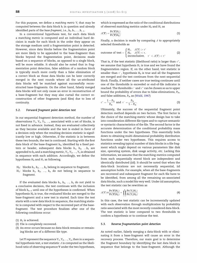
For this purpose, we define a matching metric Yi that may be
computed between the data block bi in question and alreadyidentified parts of the base-fragment, i.e., b0;b1;.; bi"1.
In a conventional hypothesis test, for each data blocka matching metric is computed and an individual hard de-cision is made for each block in the order they appear onthe storage medium until a fragmentation point is detected.However, since data blocks before the fragmentation pointare more likely to be appended to the base-fragment thanblocks beyond the fragmentation point, decisions madebased on a sequence of blocks, as opposed to a single block,will be more reliable. It should also be noted that in frag-
mentation point detection, false addition of a random blockis typically much more costly than a false elimination ofa correct block as those data blocks can be later correctlymerged in the next rounds where all the un-attributeddata blocks will be matched against successfully recon-structed base-fragments. On the other hand, falsely mergeddata blocks will not only cause an error in reconstruction ofa base-fragment but they may also curtail the correct re-construction of other fragments (and files) due to loss ofcontinuity.
5.2. Forward fragment point detection test
In our sequential fragment detection method, the number ofobservations Y1, Y2, Y3, ., associated with a set of blocks, isnot fixed in advance. Instead, they are evaluated collectivelyas they become available and the test is ended in favor ofa decision only when the resulting decision statistic is signif-icantly low or high. Otherwise, if the statistic is in between
these two bounds, the test is continued. Starting with the firstdata block of the base-fragment b0, identified by a fixed pat-tern or header, subsequent data blocks b1, b2, .bn areappended to b0 and a matching metric, Y1, Y2, ., Yn is obtainedin sequence with each addition. Accordingly, we define thehypotheses H0 and H1 as following.
H0: blocks b1, b2, ., bn belong in sequence to fragment;H1: blocks b1, b2, ., bn do not belong in sequence to
fragment.
If the evaluated data blocks b1, b2, ., bn do not yield toa conclusive decision, the test continues with the inclusionof block bnþ1 until one of the hypotheses is confirmed. Whenhypothesis H0 is true, the evaluated blocks are merged to thebase-fragment and a new test is started. Each time the teststarts with a new data block in sequence, the matching statis-tic is computed with respect to the recovered part of the base-fragment. The test procedure finalizes after one of thefollowing conditions occur:
(1) H1 is achieved.(2) File is completely recovered.
(3) An error occurs because no data-block remains or remain-ing blocks are of a different file type.
Let Y represent the sequence Y1, Y2, ., Yn, then in a sequen-tial hypothesis test, a test statistic L is computed as the likeli-hood ratio of observing sequence Y under the two hypotheses,
which is expressed as the ratio of the conditional distributions
of observed matching metrics under H0 and H1 as
LðYÞ ¼ PrðYjH1ÞPrðYjH0Þ
: (1)
Finally, a decision is made by comparing L to appropriatelyselected thresholds as
outcome of test ¼
8<
:
H1; LðYÞ > sþ
H0; LðYÞ < s"inconclusive; s" < LðYÞ < sþ
(2)
That is, if the test statistic (likelihood ratio) is larger than sþ,we assume that hypothesis H1 is true and we have found thefragmentation region. If, on the other hand, test statistic issmaller than s", hypothesis H0 is true and all the fragmentsare merged and the test continues from the next sequential
block. Finally, if neither cases are true testing continues untilone of the thresholds is exceeded or end-of-file indicator isreached. The thresholds s" and sþ can be chosen so as to upperbound the probability of errors due to false-eliminations, Pfr,and false additions, Pfe as (Wald, 1947)
sþ ¼ 1" Pfe
Pfaand s" ¼ Pfe
1" Pfa: (3)
Ultimately, the success of the sequential fragment pointdetection method depends on two factors. The first factor is
the choice of the matching-metric whose design has to takeinto consideration different file types and to capture semanticor syntactic characteristics of the file. The second factor is theaccurate determination of the conditional probability massfunctions under the two hypotheses. This essentially boilsdown to obtaining multi-dimensional probability distributionfunctions under two hypotheses. This requires access tostatistics revealing typical number of data blocks in a file frag-ment which might depend on various parameters like disksize, operating system, disk usage activity, etc. Lacking thisinformation, we assume that the matching-metrics computed
from each sequentially stored block are independent andidentically distributed (iid). It should be noted that when thedata-block locations are not necessarily sequential, iidassumption holds. For example, when all the base-fragmentsare recovered and subsequent fragment for each file have tobe identified, from among all the remaining un-associateddata blocks, such a model fits very well. Under iid assumption,the test statistic can be rewritten as
LðYÞhPrðYjH1ÞPrðYjH0Þ
¼Yn
i¼1
PrðYijH1ÞPrðYijH0Þ
: (4)
In this case, the test statistic can be incrementally updatedwith each observation through multiplication by probabilityratio associated with the most recently considered data-block.The test statistic is later compared to two thresholds to
confirm a hypothesis or to continue the test.
5.3. Reverse fragmentation point detection
As noted earlier, falsely merging a data-block with or elimi-nating it from a base-fragment will cause an error in therecovery process. Therefore, our main goal is to determinethe fragment boundary by identifying the last data block insequence that belongs to the base-fragment. Although the
d i g i t a l i n v e s t i g a t i o n 5 ( 2 0 0 8 ) S 2 – S 1 3S8

above sequential fragment detection procedure provides an
advantage in avoiding false additions and false-eliminationsby not making a decision when the information is inconclusive,it also makes accurate fragmentation point detection difficult.This is because each decision is made only after a window of ob-servations is made, and a fragmentation point can be anywherein this sequence and the test cannot accurately determine it.
To cope with this problem we propose to conduct a reversesequential test every time the (forward) test is inconclusiveand the test statistic has to be updated by considering a newdata-block. Since for a given window of observations (ina forward test) Y1, Y2, ., Yn the observations towards the
end of the block are more likely to be due to random datablocks, by visiting them first reverse test enables more accu-rate detection of the fragmentation point. In a reverse hypoth-esis test, the test statistic is computed by traversing themeasured matching-metrics in reverse order, i.e., sequenceYn, Yn"1, ., Y2. The test starts by considering Yn only. If thetest evaluates H1 as true (bn does not belong to base-fragment),the test is started with Yn"1, and if H1 is evaluated true thereverse test is terminated and the forward testing continues.On the other hand, if the reverse test is inconclusive, thetest continues by considering the next to last data blocks,
i.e., Yn, Yn"1, until a decision is reached. The fragmentationpoint is deemed to be the most recently eliminated data-blockbefore the test finally confirms the H1 hypothesis. Fig. 6 showsthe flow diagram of the fragment point detection algorithm.
Another issue is that the recovery of the base-fragment willbe continued via merging new blocks to it every time the testterminates in favor of H0. However, it must be noted that thedesignated test statistics Y, by its definition, is computedbetween the known parts of the base-fragment and the blocksin question. Therefore, when both the forward and backwardtests are inconclusive and further blocks considered do not
form a boundary with the recovered part of the image, thetest has to be forcefully terminated. In this case the fragmen-tation point is assigned to the last block that ended the test infavor of the H0 hypothesis and the blocks that cannot bedecided are not added to the base-fragment.
Having identified the fragmentation point by itself is notenough (unless the fragmentation point is the end of file) forrecovery. Once the base-fragment has been identified, thestarting block of the next fragment belonging to the file beingreconstructed needs to be determined. In the next section wepresent a new model for a file carver and then present a mod-ified version of the PUP algorithm that utilizes SHT for a com-
plete recovery solution.It should be remembered that false eliminations (fragmen-
tation point is identified before actual identification point) arepreferable over false additions (late detection of fragmenta-tion point), since the second step of the carving (close regionsweep, described in the next section) will look at a large num-ber of potential fragments to determine the next block to buildthe file and the falsely eliminated block will be reconsidered.
6. Refined file carving
As mentioned earlier, Garfinkel shows that files with greaterthan four fragments are rare, and file systems will almost
never fragment a file on a block by block basis. What this
means is that fragments typically consist of tens if not hun-dreds or thousands of blocks. We, therefore, propose a carvingsystem that takes into account the fact that fragments typi-cally consist of multiple blocks. In essence we believe thata file carver needs to find the fragmentation points of eachfile by sequentially testing each block after the header block.So our refined file carver will then contain the following steps:
(1) Identify starting block of file.(2) Sequentially check each block after first and determine
fragmentation point/file end.
(3) If fragmentation point is detected, find starting point ofnext fragment.
(4) Continute with step 2 from starting point of next fragment.
The first step in the new file carving system is the same asthe traditional step for file carving – identify the data blocksthat include the file header. The information from this initialdata block is then utilized to recover the base-fragmentthrough analysis of the neighboring blocks until a fragmenta-tion point is detected. Once the fragmentation point is deter-mined the starting block of the subsequent fragment must
be determined. Using information from the file recovered sofar the next fragmentation point (if the file has more thantwo fragments) has to be identified. This process is repeateduntil the file is completely or partially recovered from all theavailable fragments. Based on this we have modified the PUPalgorithm as described earlier with SHT.
6.1. SHT–PUP
Recall that PUP was an algorithm developed to build multiplefiles in parallel. Its major drawback was that it did not takeinto account the fact, that fragments typically consist ofmany blocks. We have developed a solution for file carvingfragmented files using SHT and PUP, called SHT–PUP. SHT–PUP begins by choosing all available headers of a file-typeand attempting to use sequential hypothesis testing asdescribed above to determine the base-fragment and frag-mentation point. Once the fragmentation point of each base-fragment is identified, the remaining available blocks are
classified into bins on the basis of file type. This is realizedby the use of keyword and statistical tests.
Keyword tests utilize the Aho–Corasick algorithm (Aho andCorasick, 1975), which is a string searching algorithm thatlocates elements of a finite set of strings within an inputtext. It matches all patterns ‘‘at once’’, so the complexity ofthe algorithm is linear in the length of the patterns plus thelength of the searched text plus the number of outputmatches. The statistical tests are exactly the same describedin Section 4 and involve entropy of the data and the OSCARmethod (Karresand and Shahmehri, 2006a,b).
It is shown in Garfinkel (2007) that the gap between frag-
ments is rarely more than 80 blocks and that the majority ofthe time the gap is much smaller. In fact a gap size of 8 blocksoccurs in 4327 files and the next closest was a gap size of32 blocks that occurs in 1519 blocks. As a result, we developeda process called the close region sweep to determine the startingpoint of the next fragment. For each base-fragment and
d i g i t a l i n v e s t i g a t i o n 5 ( 2 0 0 8 ) S 2 – S 1 3 S9

fragmentation point identified, we look at the bin of the file-type and attempt to decode each of the blocks in an area of
about 5000 blocks next to the base-fragment. For each filebeing recovered we store the top 20 block results based onour matching metric. If file i is the file with the best of the 20results say block bx, then we merge this block to the base-frag-ment of i. We then proceed with sequential hypothesis testingagain until, another fragmentation point is found. We thenstore the best 20 results for the fragmentation point exactlyas we described earlier. We repeat this process until all filesare built or have failed in finding good candidates.
SHT–PUP has the advantage of only serially comparingblocks until a fragmentation point is detected, and attempting
to then continue from the ‘‘best’’ of available fragmentationpoints of all available files. Assuming a good matching metric,files with blocks yielding better matching metric scores, willbe built first, thus reducing the blocks required to analyzefor the other file recoveries.
6.2. Bifragment gap carving with SHT
In addition, fragmentation point detection can also be used toenhance the efficiency of BGC. Recall that starting with a gapsize of 1 all possibilities of blocks between a header and footerare carved. If bf is the ending point of the first fragment and bs
is the starting block of the next fragment, every combination
of bf starting with bf greater than bhþ1 (block after header),needs to be evaluated. By utilizing fragmentation point detec-
tion, we can improve this by starting bf at ba where ba is thedetected fragmentation point. For base-fragments with hun-dreds of files this dramatically improves the performance ofthis algorithm.
7. Experiments and results
In this section, we demonstrate the use of the proposed frag-
mentation point detection algorithm by focusing on JPEG filerecovery. Essentially this requires designating a propermatching metric, i.e., Y, and obtaining the conditional proba-bilities under two hypotheses, i.e., Pr(YjH1) and Pr(YjH0), asdefined in Section 4. We will then present the performanceresults of the method for DFRWS 2006 and DFRWS 2007 test-sets.
7.1. Choice of matching metric
A matching metric is required to determine the likelihood thata block follows another in the correct reconstruction of a file.The metric is used to calculate the conditional probabilities inthe above mentioned two hypotheses that indicate a block fol-lows another. Motivated by the fact that local smoothness
(Y) >= µ1 (Y) <= µ0Fragmentation Point DetectedYes No
Fragmentation Point Detected
Make DecisionY = {Y1, Y2...Yn}
(Y)
Terminal
EOF
Yes
No
File Recovered No FurtherFragmentation Found
Yes
No
No
Merge Blocks i=1,2...nYes
Block nEvent Yn
Fig. 6 – Flow diagram of fragmentation point detection algorithm.
d i g i t a l i n v e s t i g a t i o n 5 ( 2 0 0 8 ) S 2 – S 1 3S10

assumptions often hold for natural images, Memon et al. (Paland Memon, 2006; Pal et al., 2003; Shanmugasundaram and
Memon, 2003) propose to use the discontinuity between twoneighboring image blocks as a means to determine the likeli-hood of a block following another. This is realized by comput-ing the sum of differences across the RGB pixel valuesbetween the edges of two image blocks and is then normalizedby the number of pixels used in the calculation. This returnsa score between 0 and 1 where a score is assumed to indicatea better match. Fig. 7 shows a very simple example of an im-age only five pixels long and two blocks being compared forthis image.
7.2. Estimation of model probabilities
The conditional probability density functions for the match-ing-metric Y, P(YjH0) and P(YjH1), are obtained empiricallyfrom two training sets of 600 images that were randomly
collected and had varying JPEG compression ratios and resolu-
tions. (It should be noted that the training sets did not includeimages included in DFRWS 2006 or 2007 test-sets.) In obtainingP(YjH0), model for fragments that belong together, we mea-sured the variation in Y by computing it for each block basedon the matching metric in each image with its correct nextblock. For the model where fragments are merged incorrectly,we randomly took three or more fragments from each imageand attempted to find 10 other blocks from other imagesthat decoded without an error and obtained observations ofY based on the matching metric only for those blocks thatcan be decoded correctly. Fig. 8 provides the conditional prob-
abilities. It can be seen that the resulting Y values in bothcases are significantly apart from each other. We set thethresholds desiring a detection rate of 0.7 and false elimina-tion rate of 10"15.
While we use existing models to determine Pr(YjH0), webelieve that a further improvement can be achieved bydynamically building a model for each image. By evaluatingpixel-wise differences in the recovered parts of an image, wecan build and refine the model by also updating it with thesubsequently merged blocks.
7.3. Results
Using these models, the proposed method on fragmentationpoint detection, as described in Fig. 6, is applied to recoverJPEG images in DFRWS 2006 and 2007 test cases. We must
note again that during fragmentation point detection false-eliminations (i.e., a fragmentation point is identified beforethe actual fragmentation point) are preferable over false-addi-tions (i.e., fragmentation point identified belongs to anotherfile). This is because the second step of the carving in PUPand BGC can look at a large number of potential fragmentsto determine the next block to build the file and the falselyeliminated blocks will be in contention for being chosen. Onthe other hand, manual intervention is required to recoverfrom a false addition.
4 5
1 2 3
4 5
321
Fig. 7 – Simple example of which pixels are comparedagainst which pixels.
Fig. 8 – Model for both correct and incorrect mergings of JPEG blocks.
d i g i t a l i n v e s t i g a t i o n 5 ( 2 0 0 8 ) S 2 – S 1 3 S11

Both the DFRWS 2006 and 2007 challenge test-sets lack
a file table, therefore, the default block size is set to 512 bytes.The DFRWS 2006 challenge test set consists of 14 JPEG imagesof which only 7 are fragmented. Each of the seven fragmentedJPEGs have only two fragments (i.e., are bi-fragmented). Inaddition, the second fragment of each fragmented image isin front of the starting fragment (i.e., had a greater block num-ber than the starting fragment). The DFRWS 2007 challengetest set contains 19 JPEGs only one of which is not fragmented.In addition, a few of the JPEGs have three or more fragments.One of the JPEGs has six fragments. To make the reassemblyproblem even harder, some fragments are stored in a location
behind the correct fragment that precedes it. In other words,the fragmentation point of a fragment has a block numbergreater than the starting point of the next fragment. Thismakes recovery much trickier and as a result our close regionsweep aspect of the SHT–PUP algorithm looks after and beforethe fragmentation point. Finally, some of the JPEGs have delib-erately introduced errors causing our decoder to fail. SomeJPEGs also have missing fragments. We do not attempt to cor-rect or recover from decoding errors or missing fragments.
We now present the results for both SHT–PUP, BGC andBGC with SHT, SHT–BGC. It should be noted that we initially
implemented BGC based solely on information provided inGarfinkel (2007). However, the resulting implementation hada running time of 80 min for recovering all images in DFRWS2006. We then modified, the algorithm to detect the first blockthat failed to decode after the header of an image, and ensuredthat bf (the ending point of the base-fragment) was checkedstarting from the block prior to the one that failed to decode.Then for each legitimate gap size, we moved bf to the left untilit reached the header. This reduces the running time to 22 minfor DFRWS 2006 test-set. This, technique when utilized withSHT, reduces the running time to 5 s. An alternative imple-
mentation for BGC is instead to start bf at the block beforethe decoding error as described earlier and try all possiblegap sizes before moving left for the new bf.
Even without SHT this implementation takes only 11 s torecover all images from DFWRS 2006 test-set as compared toSHT–BGC which took 5 s. Results are obtained based on thelatter described implementation of BGC.
Table 2 provides the results of recovery using DecodingDetection, BGC as well as SHT–PUP. Decoding detection is noth-ing more than decoding until an error occurs or the image isbuilt. While this cannot recover fragmented images, it isimportant to show how it also fails to identify fragmentation
points correctly and even more importantly, how it causesfalse additions (8 in 2007 and 1 in 2006). Finally, decodingdetection does not cause false eliminations since it mergesall blocks that can be successfully decoded.
In contrast, our SHT–PUP causes zero false additions, how-ever, there are a total of five false eliminations. All five of thefalsely eliminated images are fully recovered, and this isbecause the close region sweep phase correctly identifiesthat the first falsely eliminated block for each fragment be-longs to the fragment (it has the best score of the other 5000blocks checked). It should be noted that due to deliberately
introduced decoding errors and missing blocks some JPEGsare unable to be fully recovered, however, in all but one casewe are able to achieve the best possible construction.
It is also interesting to note that three of the falsely elimi-nated images have a detected fragmentation point exactly
one block prior to the actual fragmentation point (false elimi-nation). A closer inspection reveals that these cases occurwhen the test for a block is inconclusive and the next blockcauses a decoding error. Our method by default discards blocksthat are undecided if a validation fails to avoid a false-addition.These blocks are later detected to belong to correct fragmentsduring the recovery phase. In DFRWS 2006, we are able to re-cover all seven fragmented images without a problem. InDFRWS 2007 we are able to recover all but two decodable (with-out errors) fragmented images without manual intervention.One of the two images, is also manually recoverable by identi-
fying the incorrect block and simply stating that it should notconsidered for the next reassembly iteration.
8. Conclusion
In this paper, we have demonstrated the effectiveness ofusing sequential hypothesis testing for identifying the frag-mentation point for JPEGs. We have shown the advantages
of true content based recovery compared to techniques thatsolely utilize decoding or file structural errors for recovery.Additional work will be done in building and refining themodels for a file as it is being built. In future work, we planto create models for other file formats, like those of MicrosoftOffice, Email (PPT files), etc. In addition, we wish to improve
Table 2 – Recovery results for DFRWS 2006 and 2007 test-sets
DFRWS 2006 2007
Total images 14 18Fragmented images 7 17Un-fragmented images 7 1
Decoding detectionRecovered un-fragmented 7 1False elimination 0 0False addition 1 8Fragmentation point detected 5 9Recovered fragmented 0 0Total recovered 7 1
Bi-fragmented gap carvingRecovered un-fragmented 7 1False elimination 0 0False addition 1 8Fragmentation point detected 5 9Recovered fragmented 0 2Total recovered 14 1Time taken 9 s HoursTime with SHT 5 s Hours
SHT PUPRecovered un-fragmented 7 1False elimination 2 3False addition 0 0Fragmentation point detected 5 14Recovered fragmented 7 16Total recovered 14 17Time taken 13 s 3.6 min
d i g i t a l i n v e s t i g a t i o n 5 ( 2 0 0 8 ) S 2 – S 1 3S12
the accuracy and efficiency of the close region sweep phase by
identifying the most likely candidates for the next fragment’sstarting point. Finally additional work needs to be conductedin recovering from decoding errors as well as identifying andhandling missing fragments.
r e f e r e n c e s
Aho, Corasick M. Fast pattern matching: an aid to bibliographicsearch. Communications on ACM June 1975;18(6):333–40.
Amiga Smart Filesystem. http://www.xs4all.nl/hjohn/SFS.Carrier Brian. File system forensic analysis. Pearson Education;
March 2005.Carrier B, Wietse V, Eoghan C. File carving challenge 2006, http://
www.dfrws.org/2006/challenge; 2006.Carrier B, Wietse V, Eoghan C. File carving challenge 2007, http://
www.dfrws.org/2007/challenge; 2007.Dijkstra EW. A note on two problems in connexion with graphs.
Numerische Mathematik 1959;1:269–71.Garfinkel S. Carving contiguous and fragmented files with fast
object validation. In: Proceedings of the 2007 digital forensicsresearch workshop, DFRWS, Pittsburgh, PA; August 2007.
Karresand Martin, Shahmehri Nahid. Oscar – file typeidentification of binary data in disk clusters and RAM pages.IFIP Security and Privacy in Dynamic Environments 2006;201:413–24.
Karresand Martin, Shahmehri Nahid. File type identification ofdata fragments by their binary structure. IEEE InformationAssurance Workshop June 2006:140–7.
McVoy LW, Kleiman SR. Extent-like performance from a UNIX filesystem. In: Proceedings of USENIX winter’91, Dallas, TX; 1991,p. 33–43.
Pal A, Memon N. Automated reassembly of file fragmentedimages using greedy algorithms. IEEE Transactions on Imageprocessing February 2006:385–93.
Pal A, Shanmugasundaram K, Memon N. Reassembing imagefragments. In: Proceedings ICASSP, Hong Kong; April 2003.
Richard III Golden G, Roussev V. Scalpel: a frugal, highperformance file carver. In: Proceedings of the 2005 digitalforensics research workshop, DFRWS; August 2005.
Shanmugasundaram K, Memon N. Automatic reassembly ofdocument fragments via context based statistical models. In:Annual computer security applications conference, Las Vegas,Nevada; 2003.
STORAGEsearch.com. Data recovery from flash SSDs? http://www.storagesearch.com/recovery.html.
Sweeney A, Doucette D, Hu W, Anderson C, Nishimoto M, Peck G.Scalability in the XFS file system. In: Proceedings of theUSENIX 1996 annual technical conference, San Diego, CA;1996.
Wald A. Sequential analysis. New York: Dover; 1947.
Anandabrata Pal is doing his PhD degree in Computer Science
at Polytechnic University. He is specializing in File Carving andData Recovery. His research interests also include code obfus-cation and file system forensics.
Husrev T. Sencar received his PhD degree in electrical engi-neering from New Jersey Institute of Technology in 2004. Heis currently a postdoctoral researcher with Information Sys-tems and Internet Security Laboratory of Polytechnic Univer-sity, Brooklyn, NY. His research interests lie in security ofmultimedia and communication.
Nasir Memon is a Professor in the Computer Science Depart-ment at Polytechnic University, New York. He is the directorof the Information Systems and Internet Security (ISIS) lab atPolytechnic. His research interests include Data Compression,Computer and Network Security, Digital Forensics, and Multi-media Data Security.
d i g i t a l i n v e s t i g a t i o n 5 ( 2 0 0 8 ) S 2 – S 1 3 S13