detection of light - leiden universityhome.strw.leidenuniv.nl/~brandl/dol/dtl_06_bolometers.pdf ·...
TRANSCRIPT
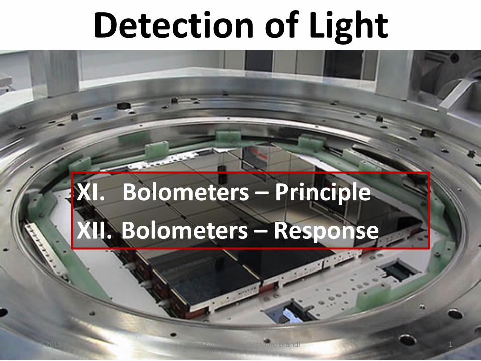
Detection of Light
XI. Bolometers – Principle XII. Bolometers – Response
17-3-2015 Detection of Light – Bernhard Brandl 1
17-3-2015 Detection of Light – Bernhard Brandl 2
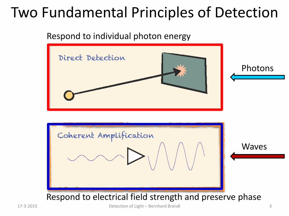
Two Fundamental Principles of Detection
17-3-2015 Detection of Light – Bernhard Brandl 3
Photons
Waves
Respond to electrical field strength and preserve phase
Respond to individual photon energy
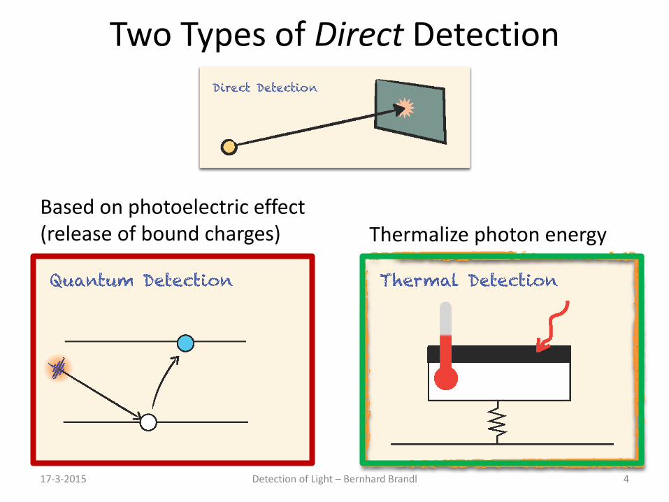
Two Types of Direct Detection
Based on photoelectric effect (release of bound charges)
17-3-2015 Detection of Light – Bernhard Brandl 4
Thermalize photon energy
17-3-2015 Detection of Light – Bernhard Brandl 5
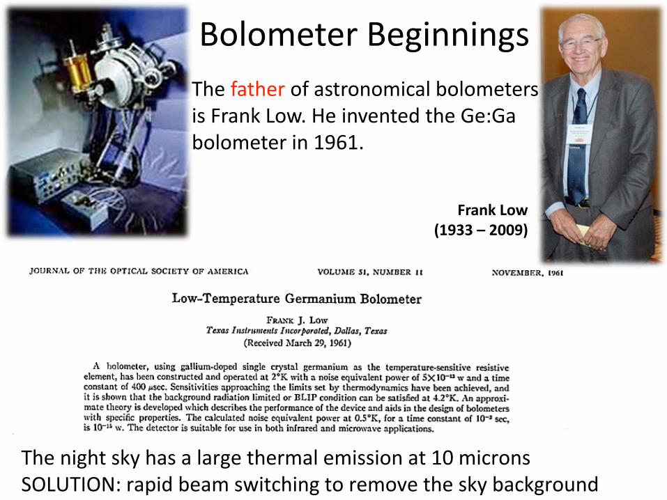
Bolometer Beginnings
17-3-2015 Detection of Light – Bernhard Brandl 6 The night sky has a large thermal emission at 10 microns SOLUTION: rapid beam switching to remove the sky background
The father of astronomical bolometers is Frank Low. He invented the Ge:Ga bolometer in 1961.
Frank Low (1933 – 2009)
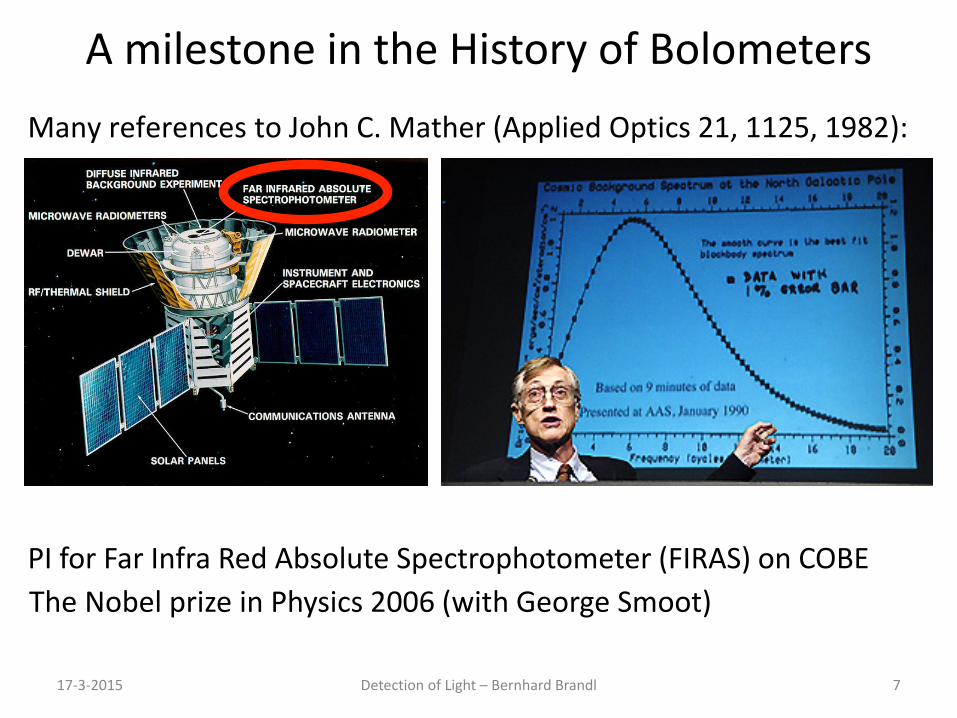
A milestone in the History of Bolometers
17-3-2015 Detection of Light – Bernhard Brandl 7
Many references to John C. Mather (Applied Optics 21, 1125, 1982):
The Nobel prize in Physics 2006 (with George Smoot) PI for Far Infra Red Absolute Spectrophotometer (FIRAS) on COBE

17-3-2015 Detection of Light – Bernhard Brandl 8
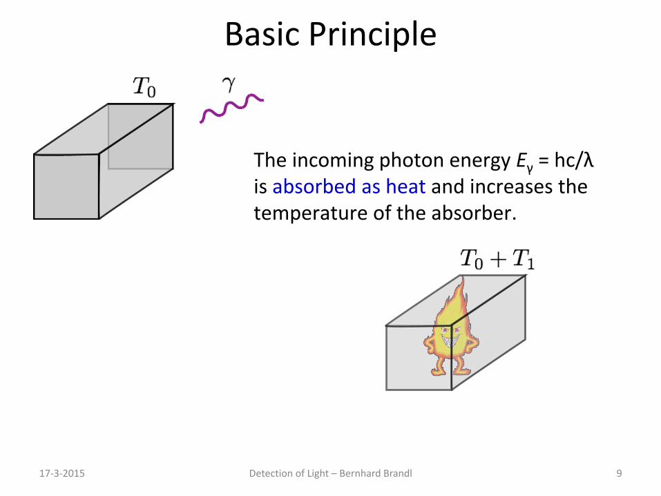
Basic Principle
17-3-2015 Detection of Light – Bernhard Brandl 9
The incoming photon energy Eγ = hc/λ is absorbed as heat and increases the temperature of the absorber.
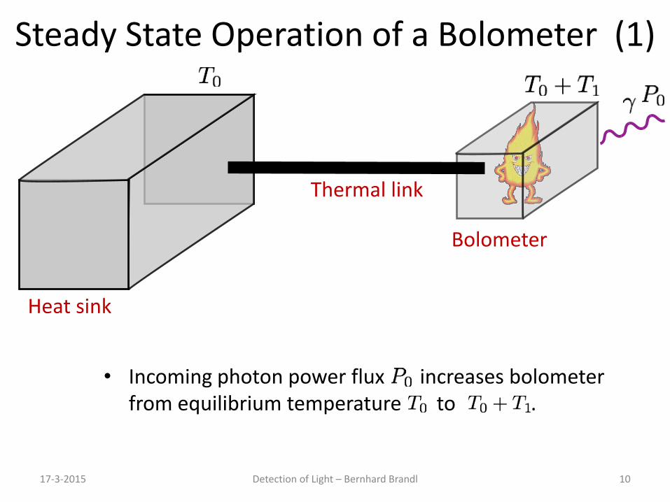
Steady State Operation of a Bolometer (1)
17-3-2015 Detection of Light – Bernhard Brandl 10
Heat sink
Bolometer
Thermal link
• Incoming photon power flux increases bolometer from equilibrium temperature to .
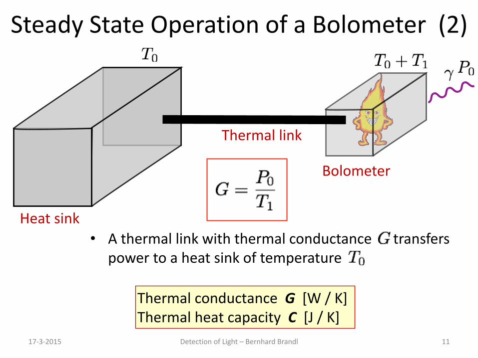
Steady State Operation of a Bolometer (2)
17-3-2015 Detection of Light – Bernhard Brandl 11
Heat sink
Bolometer
Thermal link
• A thermal link with thermal conductance transfers power to a heat sink of temperature
Thermal conductance G [W / K] Thermal heat capacity C [J / K]
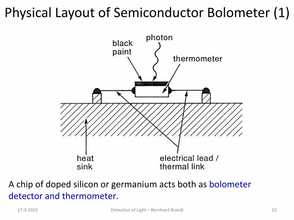
Physical Layout of Semiconductor Bolometer (1)
17-3-2015 Detection of Light – Bernhard Brandl 12
A chip of doped silicon or germanium acts both as bolometer detector and thermometer.
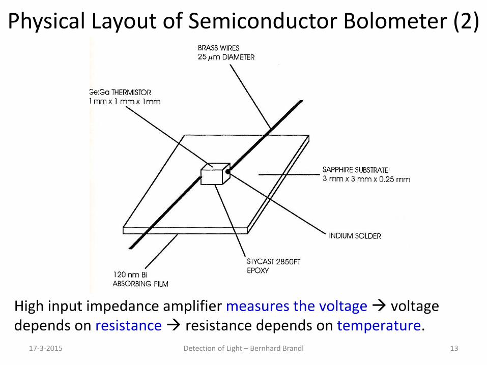
Physical Layout of Semiconductor Bolometer (2)
17-3-2015 Detection of Light – Bernhard Brandl 13
High input impedance amplifier measures the voltage voltage depends on resistance resistance depends on temperature.
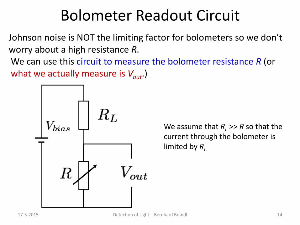
Bolometer Readout Circuit
17-3-2015 Detection of Light – Bernhard Brandl 14
Johnson noise is NOT the limiting factor for bolometers so we don’t worry about a high resistance R. We can use this circuit to measure the bolometer resistance R (or what we actually measure is Vout.)
We assume that RL >> R so that the current through the bolometer is limited by RL.

17-3-2015 Detection of Light – Bernhard Brandl 15
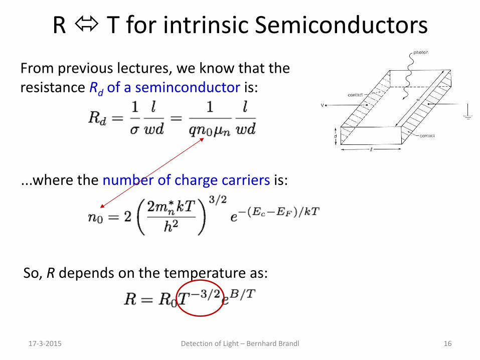
R T for intrinsic Semiconductors
17-3-2015 Detection of Light – Bernhard Brandl 16
From previous lectures, we know that the resistance Rd of a seminconductor is:
...where the number of charge carriers is:
So, R depends on the temperature as:
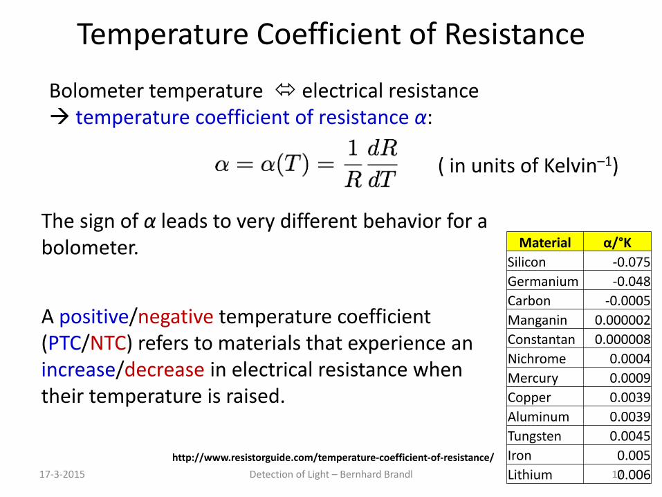
Temperature Coefficient of Resistance
17-3-2015 Detection of Light – Bernhard Brandl 17
Bolometer temperature electrical resistance temperature coefficient of resistance α:
A positive/negative temperature coefficient (PTC/NTC) refers to materials that experience an increase/decrease in electrical resistance when their temperature is raised.
The sign of α leads to very different behavior for a bolometer.
( in units of Kelvin–1)
http://www.resistorguide.com/temperature-coefficient-of-resistance/
Material α/°K Silicon -0.075 Germanium -0.048 Carbon -0.0005 Manganin 0.000002 Constantan 0.000008 Nichrome 0.0004 Mercury 0.0009 Copper 0.0039 Aluminum 0.0039 Tungsten 0.0045 Iron 0.005 Lithium 0.006
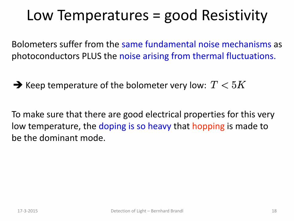
Low Temperatures = good Resistivity
17-3-2015 Detection of Light – Bernhard Brandl 18
Bolometers suffer from the same fundamental noise mechanisms as photoconductors PLUS the noise arising from thermal fluctuations.
Keep temperature of the bolometer very low:
To make sure that there are good electrical properties for this very low temperature, the doping is so heavy that hopping is made to be the dominant mode.
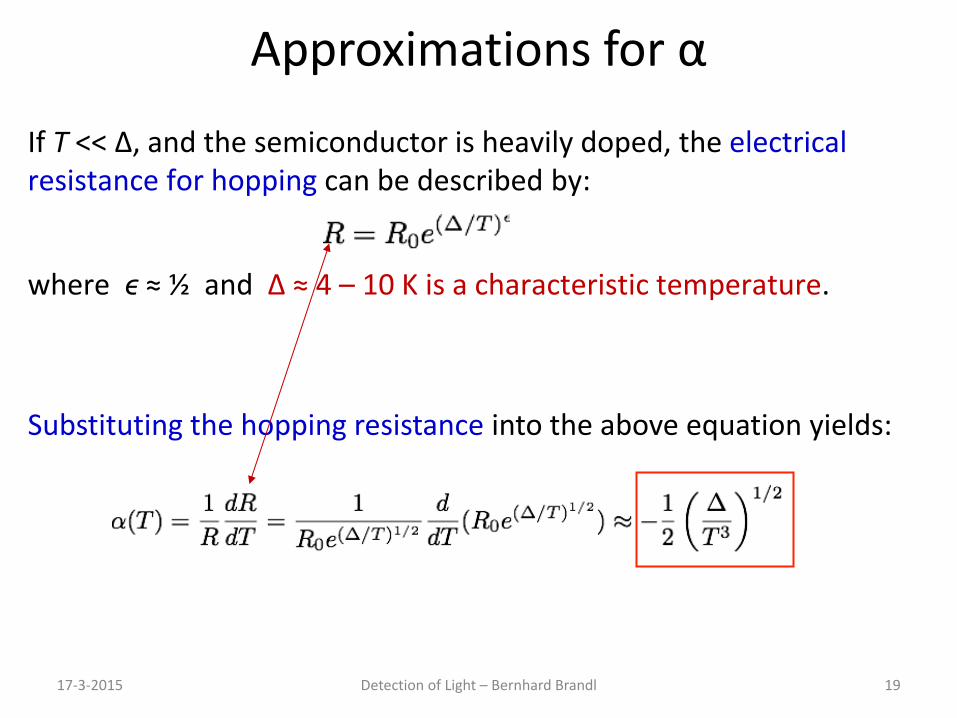
Approximations for α
17-3-2015 Detection of Light – Bernhard Brandl 19
If T << Δ, and the semiconductor is heavily doped, the electrical resistance for hopping can be described by:
where ϵ ≈ ½ and Δ ≈ 4 – 10 K is a characteristic temperature.
Substituting the hopping resistance into the above equation yields:
17-3-2015 Detection of Light – Bernhard Brandl 21
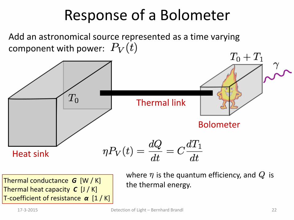
Response of a Bolometer
17-3-2015 Detection of Light – Bernhard Brandl 22
Add an astronomical source represented as a time varying component with power:
Heat sink
Bolometer
Thermal link
where is the quantum efficiency, and is the thermal energy. Thermal conductance G [W / K]
Thermal heat capacity C [J / K] T-coefficient of resistance α [1 / K]
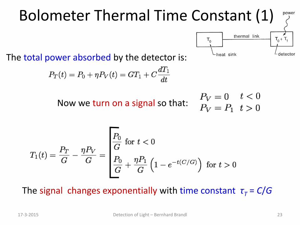
Bolometer Thermal Time Constant (1)
17-3-2015 Detection of Light – Bernhard Brandl 23
The total power absorbed by the detector is:
Now we turn on a signal so that:
The signal changes exponentially with time constant τT = C/G
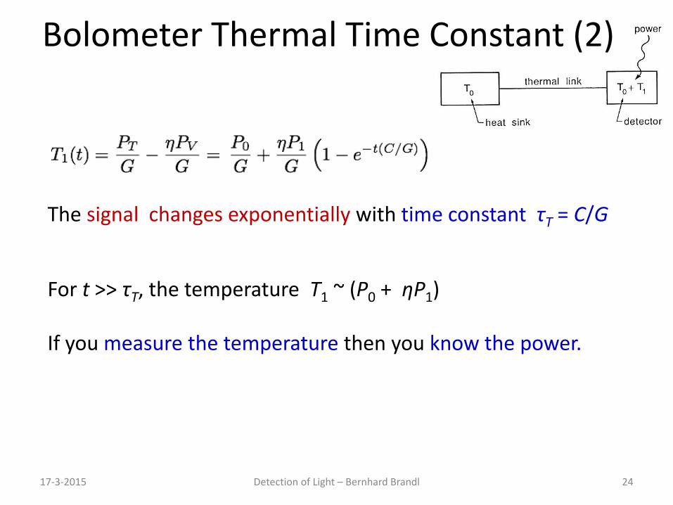
Bolometer Thermal Time Constant (2)
17-3-2015 Detection of Light – Bernhard Brandl 24
The signal changes exponentially with time constant τT = C/G
For t >> τT, the temperature T1 ~ (P0 + ηP1) If you measure the temperature then you know the power.

Two Sources of Bolometer Heating
17-3-2015 Detection of Light – Bernhard Brandl 25
1. Incoming (detected) photon flux produces PV(t):
2. Electrical heating from the current sensing in the thermometer PI:
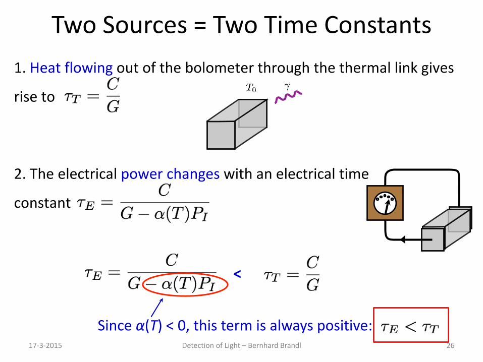
Two Sources = Two Time Constants
17-3-2015 Detection of Light – Bernhard Brandl 26
1. Heat flowing out of the bolometer through the thermal link gives
rise to
2. The electrical power changes with an electrical time
constant
Since α(T) < 0, this term is always positive:
<
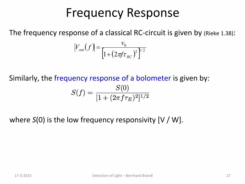
Frequency Response
17-3-2015 Detection of Light – Bernhard Brandl 27
The frequency response of a classical RC-circuit is given by (Rieke 1.38):
( )( )[ ] 2/12
0
21 RC
outf
vfVτπ+
=
where S(0) is the low frequency responsivity [V / W].
Similarly, the frequency response of a bolometer is given by:
17-3-2015 Detection of Light – Bernhard Brandl 28
Electrical Responsivity
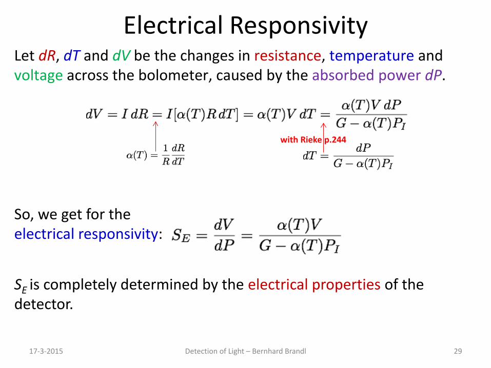
17-3-2015 Detection of Light – Bernhard Brandl 29
Let dR, dT and dV be the changes in resistance, temperature and voltage across the bolometer, caused by the absorbed power dP.
with Rieke p.244
So, we get for the electrical responsivity:
SE is completely determined by the electrical properties of the detector.
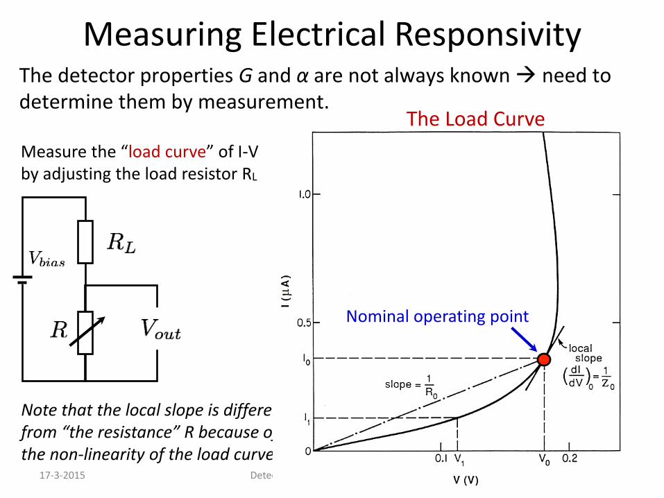
Measuring Electrical Responsivity
17-3-2015 Detection of Light – Bernhard Brandl 30
The detector properties G and α are not always known need to determine them by measurement.
Measure the “load curve” of I-V by adjusting the load resistor RL
Note that the local slope is different from “the resistance” R because of the non-linearity of the load curve.
Nominal operating point
The Load Curve
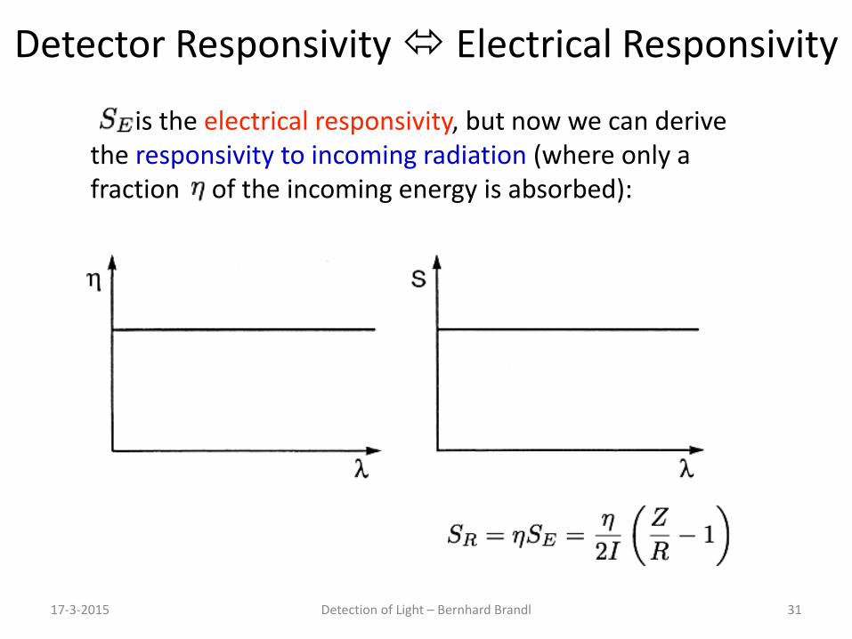
Detector Responsivity Electrical Responsivity
17-3-2015 Detection of Light – Bernhard Brandl 31
is the electrical responsivity, but now we can derive the responsivity to incoming radiation (where only a fraction of the incoming energy is absorbed):
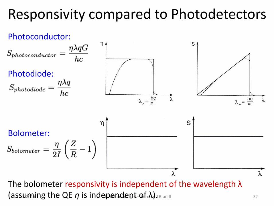
Responsivity compared to Photodetectors
17-3-2015 Detection of Light – Bernhard Brandl 32
Photoconductor:
Photodiode:
Bolometer:
The bolometer responsivity is independent of the wavelength λ (assuming the QE η is independent of λ).
17-3-2015 Detection of Light – Bernhard Brandl 33
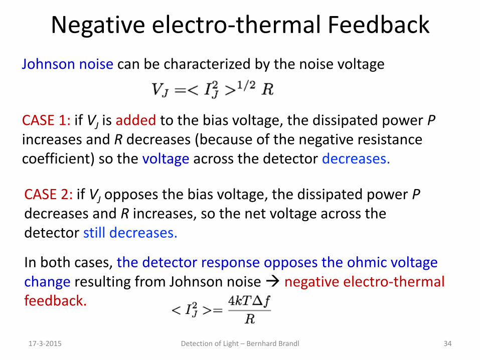
Negative electro-thermal Feedback
17-3-2015 Detection of Light – Bernhard Brandl 34
Johnson noise can be characterized by the noise voltage
CASE 1: if VJ is added to the bias voltage, the dissipated power P increases and R decreases (because of the negative resistance coefficient) so the voltage across the detector decreases.
CASE 2: if VJ opposes the bias voltage, the dissipated power P decreases and R increases, so the net voltage across the detector still decreases.
In both cases, the detector response opposes the ohmic voltage change resulting from Johnson noise negative electro-thermal feedback.
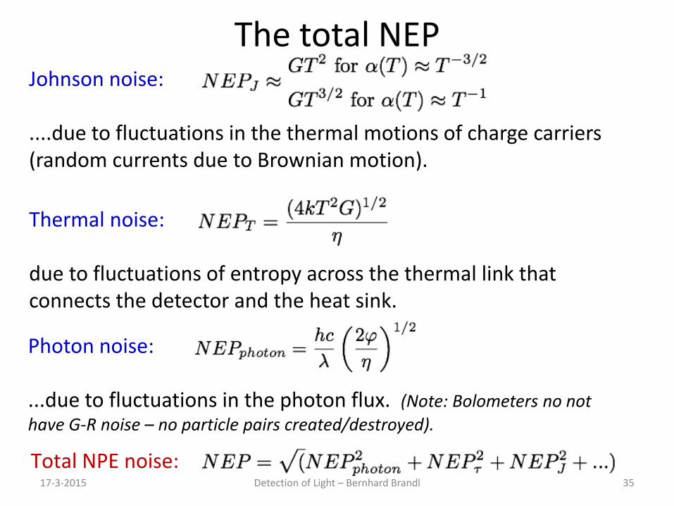
The total NEP
17-3-2015 Detection of Light – Bernhard Brandl 35
Johnson noise: ....due to fluctuations in the thermal motions of charge carriers (random currents due to Brownian motion).
Photon noise: ...due to fluctuations in the photon flux. (Note: Bolometers no not have G-R noise – no particle pairs created/destroyed).
Thermal noise: due to fluctuations of entropy across the thermal link that connects the detector and the heat sink.
Total NPE noise:
Detection of Light – Bernhard Brandl
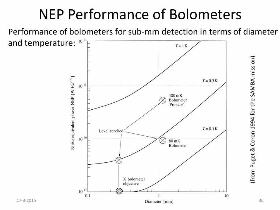
NEP Performance of Bolometers
17-3-2015 36
Performance of bolometers for sub-mm detection in terms of diameter and temperature:
(from
Pug
et &
Cor
on 1
994
for t
he S
AMBA
miss
ion)
.
17-3-2015 Detection of Light – Bernhard Brandl 37
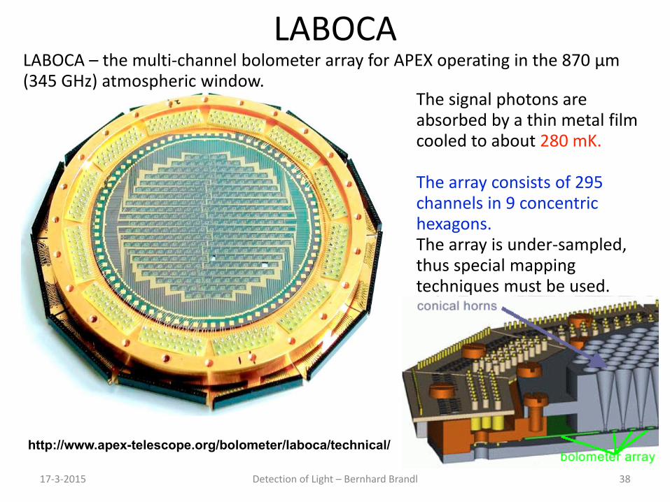
LABOCA
17-3-2015 Detection of Light – Bernhard Brandl 38
The signal photons are absorbed by a thin metal film cooled to about 280 mK. The array consists of 295 channels in 9 concentric hexagons. The array is under-sampled, thus special mapping techniques must be used.
http://www.apex-telescope.org/bolometer/laboca/technical/
LABOCA – the multi-channel bolometer array for APEX operating in the 870 μm (345 GHz) atmospheric window.
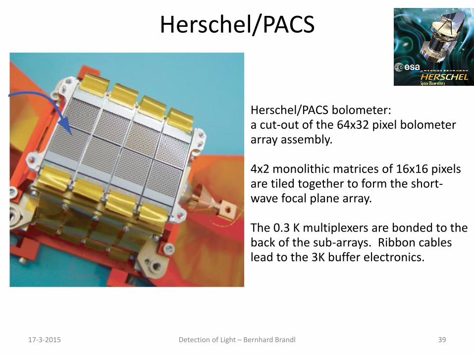
Herschel/PACS
17-3-2015 Detection of Light – Bernhard Brandl 39
Herschel/PACS bolometer: a cut-out of the 64x32 pixel bolometer array assembly. 4x2 monolithic matrices of 16x16 pixels are tiled together to form the short-wave focal plane array. The 0.3 K multiplexers are bonded to the back of the sub-arrays. Ribbon cables lead to the 3K buffer electronics.
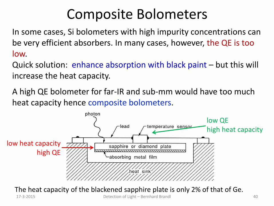
Composite Bolometers
17-3-2015 Detection of Light – Bernhard Brandl 40
In some cases, Si bolometers with high impurity concentrations can be very efficient absorbers. In many cases, however, the QE is too low. Quick solution: enhance absorption with black paint – but this will increase the heat capacity.
A high QE bolometer for far-IR and sub-mm would have too much heat capacity hence composite bolometers.
The heat capacity of the blackened sapphire plate is only 2% of that of Ge.
low heat capacity high QE
low QE high heat capacity
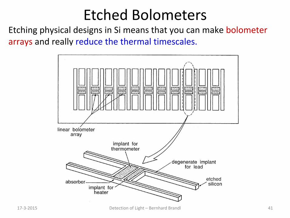
Etched Bolometers
17-3-2015 Detection of Light – Bernhard Brandl 41
Etching physical designs in Si means that you can make bolometer arrays and really reduce the thermal timescales.