determination of the striking distance of a lightning rod...
TRANSCRIPT

Turk J Elec Eng & Comp Sci
(2016) 24: 4083 – 4097
c⃝ TUBITAK
doi:10.3906/elk-1311-175
Turkish Journal of Electrical Engineering & Computer Sciences
http :// journa l s . tub i tak .gov . t r/e lektr ik/
Research Article
Determination of the striking distance of a lightning rod using finite element
analysis
Ab Halim ABU BAKAR1,∗, Alyaa ZAINAL ABIDIN2, Hazlee Azil ILLIAS1,2, Hazlie MOKHLIS1,2,Syahirah ABD HALIM2, Nor Hidayah NOR HASSAN2, Chia Kwang TAN1
1UM Power Energy Dedicated Advanced Centre (UMPEDAC), Wisma R&D University of Malaya,Kuala Lumpur, Malaysia
2Department of Electrical Engineering, Faculty of Engineering, University of Malaya, Kuala Lumpur, Malaysia
Received: 21.11.2013 • Accepted/Published Online: 08.07.2015 • Final Version: 20.06.2016
Abstract: The problems related to electromagnetic waves transmitted by lightning strikes can be studied through
physical lightning models based on laboratory results. The main concern of these models is determining the striking
distance between the leader tip and the lightning rod during lightning occurrences. The striking distance is a significant
factor in designing the lightning protection system. However, models using finite element analysis (FEA) for this purpose
are less likely to be found in the literature. Therefore, in this work, a geometry model of a lightning rod and leader was
developed using available FEA software. The model was used to determine the striking distance for different lightning
rod heights. The results obtained were compared with those of previous research using different methods to validate
the models developed using FEA software. From the comparison, the striking distance obtained from the FEA software
as a function of lightning rod height was in good agreement compared to other methods from previous research. The
use of FEA software also enables the effect of different tip radii of curvature and shapes of the lightning rod on striking
distance to be studied, which can further enhance our understanding of the relationship between striking distance and
different rod parameters.
Key words: Striking distance, finite element analysis, COMSOL
1. Introduction
Modeling of lightning requires a large number of variables, which makes the analysis complex, including
determination of striking distance [1]. The striking distance, r , is described as the gap between a lightning rod
to be struck with the leader tip when the upward progressing leader is initiated from the lightning rod [2] as
shown in Figure 1. The significance of striking distance is to estimate the lightning performance, which is mainly
used in designing lightning protection of earthed structures. Mostly, the lightning protection system contains
a lightning rod that will intercept the lightning flash and protect the structure from direct lightning strikes.
Numerous models have been successfully developed in the past to determine the striking distance against the
height of a lightning rod. These models were based on the physics of the streamer-to-leader transition and
observations made in the laboratory on long sparks to determine leader inception from a grounded structure.
The concept of striking distance described using the electrogeometrical model (EGM) is the distance
between the tip of the downward leader and the grounded structure when the final jump is established. In this
model, the presence of the connecting leader (connecting the upward and the downward leader) is neglected since
∗Correspondence: [email protected]
4083

ABU BAKAR et al./Turk J Elec Eng & Comp Sci
the striking distance is independent of the height of the grounded structure. With the presence of a connecting
leader the striking distance can be defined differently, in which the gap between the tip of the structure and the
tip of the downward leader is determined immediately after the connecting leader is initiated [3].
Figure 1. Striking distance.
In order to study the initiation of upward lightning leaders, different models have been proposed in the
past. Many studies have been performed on physical lightning models to extract information to understand
the physics of the streamer-to-leader transition. These models predict the background electric field, which is
necessary for the initiation of the upward leader inception. Eriksson’s model [4,5] utilized the critical radius
concept and has been used widely in the literature to compute the leader inception conditions on rods, masts,
power lines [6,7], and buildings [8]. In these studies, any sharp point on a structure such as the tip of lightning
rods or corners and edges of a building are rounded off to the critical radius. It was assumed that a stable leader
is initiated when the electric field on the surface is equal to the critical corona inception electric field, which is
around 3 MV m−1 at atmospheric pressure. The surface electric field depends on the shape and radius of the
rod. The experiment was done with different shapes of grounded rod and two different values of the critical
radii, namely 0.36 m [9] and 0.28 m [10]. The critical radius concept was used as a leader inception criterion
in lightning related studies by Eriksson, Dellera and Garbagnati, and D’Alessandro. The critical radius used
was 0.36 m obtained by Carrara and Thione [9] and 0.28 m obtained by Bernardi et al. [10] for a grounded
rod between two parallel plates with a 500/6000 mu s waveform. The results of the experiment show that the
critical radius concept as used today for lightning studies is strongly geometry dependent.
Another model was proposed by Rizk [11], assuming that the corona inception voltage was smaller than
the leader inception voltage from the rod. Rizk also assumed that, for the initiation of a stable leader from
the rod, potential difference and breakdown voltage of air or the electric field of the tip of the rod and the tip
of the streamer must equal or exceed a certain critical voltage gradient or breakdown voltage. According to
Petrov and Waters [12], the ambient electric field and the electric field generated by the structure must exceed
a critical electric field over the streamer zone. The streamer initiated from a given point on a structure must
extend to a critical length, which in their work was 0.7 m, before an upward leader is initiated from that point.
In Lalande’s model [13], he assumed that the leader velocity has a constant relationship with the current. From
the model, a mathematical expression for the leader inception fields to the lightning rods was derived.
From the previously developed models, several complexities arise when practical cases were analyzed.
For example, Erickson’s model was found to be less suitable to be applied for larger dimensions of lightning
inception. In [14], Rizk model’s was used to analyze the leader inception criterion for a conventional rod-to-
4084
ABU BAKAR et al./Turk J Elec Eng & Comp Sci
plane gap. However, the model was not clearly defined for buildings and complex structures as the constants
were only applicable for rods, tall masts, and transmission line models.
Petrov and Waters found that the critical streamer length contradicted the results from the laboratory
data [12]. Moreover, the empirical data obtained from the laboratory could not be used directly to model
upward leaders of lightning flashes [15]. In Lalande’s model [16], the procedure of calculating the corona charge,
which is required in quantifying the streamer-to-leader transition by this method, is only valid for structures
with axial symmetry. Moreover, the model requires knowing the number of streamer channels in the streamer
zone as an input.
Apart from experimental approaches, several numerical techniques have been used to model the lightning
attachment process. The numerical techniques include the boundary element method (BEM), the charge
simulation method (CSM), the finite difference time domain method (FDTDM), and the finite element method
(FEM). The BEM integrates the known sources within the domain and only computes the domain boundary and
was implemented by Poljak and Brebbia [17]. Meanwhile, the CSM is applicable to areas containing unbounded
regions [18]. The FDTDM requires long computation time and large memory for the complex geometries.
Although numerous studies have been conducted on the application of lightning rods, models using the
FEM are less likely to be found in the literature [19–21]. The FEM is a convenient method for areas with
many dielectrics, inhomogeneous and nonlinear materials, complex fields, and areas containing distributed
space charges and singular points. In this work, the striking distance as a function of lightning rod heights
was developed using available FEA software, which is COMSOL Multiphysics 4.3. A two-dimensional (2D)
propagation leader and lightning rod were modeled on the XY-plane to obtain the electric field distribution
in the model. The field distribution was used to determine the striking distance, by estimating the distance
between a leader and lightning rod tips, which yields a potential gradient of lightning streamers. The results
from the simulation were compared with those of the existing models to verify the striking distance obtained
using the FEA model as a function of lightning rod height. In addition, various designs of the lightning rod
were simulated by varying the shape and tip radius of curvature to investigate their influence on the striking
distance. The use of FEA software can further enhance our understanding of the relationship between striking
distance and different rod parameters through the electric field distribution calculation.
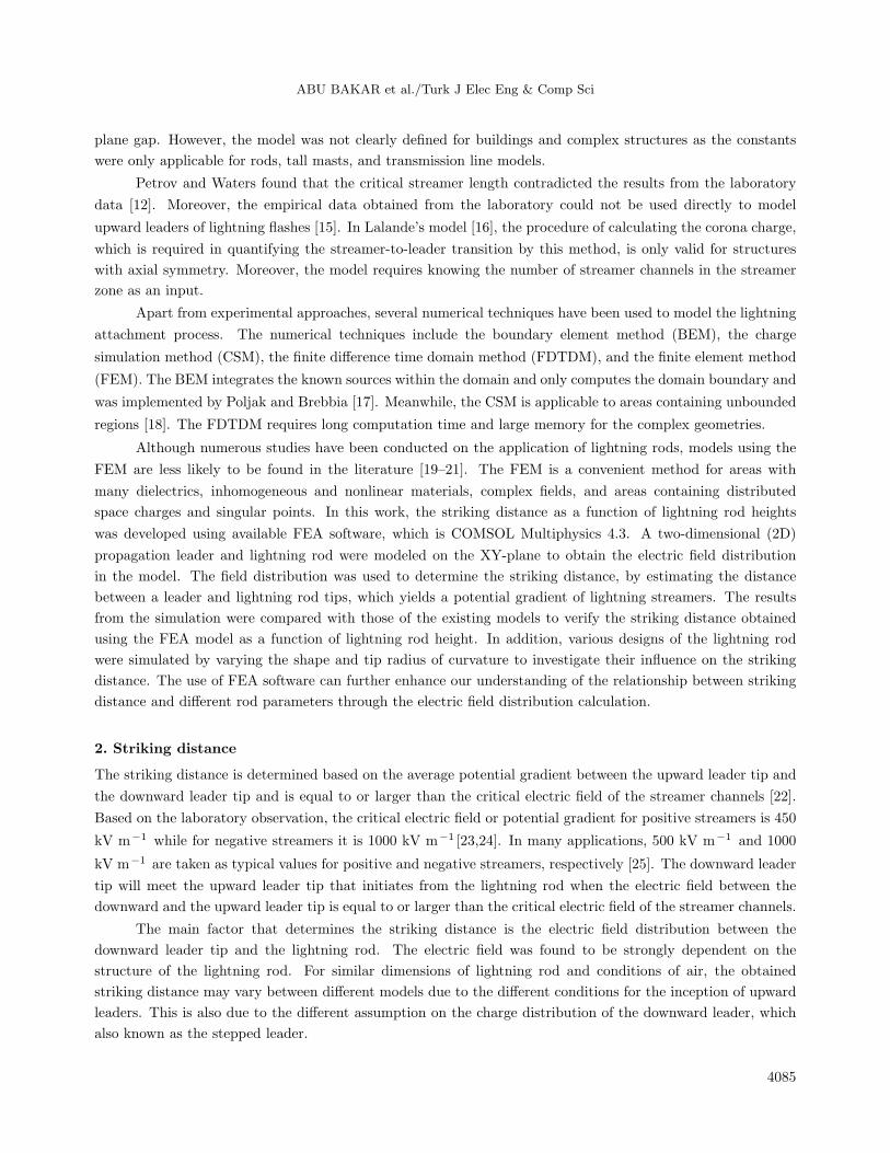
2. Striking distance
The striking distance is determined based on the average potential gradient between the upward leader tip and
the downward leader tip and is equal to or larger than the critical electric field of the streamer channels [22].
Based on the laboratory observation, the critical electric field or potential gradient for positive streamers is 450
kV m−1 while for negative streamers it is 1000 kV m−1 [23,24]. In many applications, 500 kV m−1 and 1000
kV m−1 are taken as typical values for positive and negative streamers, respectively [25]. The downward leader
tip will meet the upward leader tip that initiates from the lightning rod when the electric field between the
downward and the upward leader tip is equal to or larger than the critical electric field of the streamer channels.
The main factor that determines the striking distance is the electric field distribution between the
downward leader tip and the lightning rod. The electric field was found to be strongly dependent on the
structure of the lightning rod. For similar dimensions of lightning rod and conditions of air, the obtained
striking distance may vary between different models due to the different conditions for the inception of upward
leaders. This is also due to the different assumption on the charge distribution of the downward leader, which
also known as the stepped leader.
4085
ABU BAKAR et al./Turk J Elec Eng & Comp Sci
The striking distance depends on the electric field magnitude, which is influenced by the distribution of
charge on the stepped leader channel. The charge distribution of the leader channel was proposed by Cooray et
al. [26]. They found a solid connection between the charge distribution and the first return stroke current. In
their study, they assumed that the stepped leader channel is vertical. According to the results, a linear charge
distribution (in C/m) on the stepped leader channel when its tip is at a height above ground is given by
ρ(ζ) = a0
(1− ζ
H − z0
)G(z0)Ip +
Ip(a+ bζ)
1 + cζ + dζ2J(z0), (1)
where
G(z0) = 1− z0H
(2)
J(z0) = 0.3 e− z0−10
75 +0.7G(z0) (3)
z0 ≤ 10m
a0= 1.476× 10⁻⁵, a = 4.857× 10⁻⁵, b = 3.9097× 10⁻⁶, c = 0.522, d = 3.73× 10⁻³
ρ(ζ) = charge per unit length of a leader section located at height z (in Coulomb per meter)
ζ = length along the stepped leader channel with ζ = 0 at the tip of the leader in meters
Ip =return stroke peak current in kA
H =height of the clouds in meters
z0 =height of the leader tip above the ground in meters
From the linear charge distribution on the stepped leader channel, the electric field at a certain point can
be determined [22]
Ez =
L∫0
ρ(z)zdz
2πε0(D2 + z2)3/2
, (4)
where
L = length of the leader channel in meters
ρ(z) = linear charge distribution (C/m)
ε0 = permittivity of free space
D = lateral distance from the base of the channel to the strike point
3. FEA model
Figure 2 shows a 2D geometric model that has been developed using FEA software, namely COMSOL Multi-
physics. The model consists of a leader and grounded lightning rod surrounded by air [22]. Air was included
in the model to obtain the electric field distribution between the rod and leader tip. A hemisphere geometry
with radius of 5000 m and a single line with length of 4000 m are assigned as the air domain and the downward
leader, respectively. The striking distance was determined by the distance between the downward leader tip and
the tip of the lightning rod when the potential gradient between these two tips equals 500 kV m−1 . In other
words, while maintaining the position of the lightning rod, the position of the leader tip was adjusted until the
potential gradient between the two tips equaled 500 kV m−1 , since a positive streamer was used.
4086
ABU BAKAR et al./Turk J Elec Eng & Comp Sci
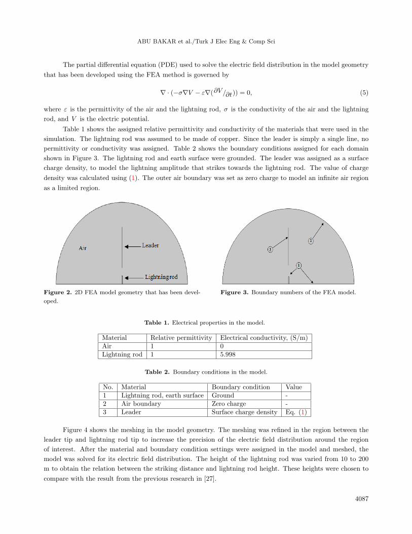
The partial differential equation (PDE) used to solve the electric field distribution in the model geometry
that has been developed using the FEA method is governed by
∇ · (−σ∇V − ε∇(∂V /∂t)) = 0, (5)
where ε is the permittivity of the air and the lightning rod, σ is the conductivity of the air and the lightning
rod, and V is the electric potential.
Table 1 shows the assigned relative permittivity and conductivity of the materials that were used in the
simulation. The lightning rod was assumed to be made of copper. Since the leader is simply a single line, no
permittivity or conductivity was assigned. Table 2 shows the boundary conditions assigned for each domain
shown in Figure 3. The lightning rod and earth surface were grounded. The leader was assigned as a surface
charge density, to model the lightning amplitude that strikes towards the lightning rod. The value of charge
density was calculated using (1). The outer air boundary was set as zero charge to model an infinite air region
as a limited region.
Figure 2. 2D FEA model geometry that has been devel-
oped.
Figure 3. Boundary numbers of the FEA model.
Table 1. Electrical properties in the model.
Material Relative permittivity Electrical conductivity, (S/m)Air 1 0Lightning rod 1 5.998
Table 2. Boundary conditions in the model.
No. Material Boundary condition Value1 Lightning rod, earth surface Ground -2 Air boundary Zero charge -3 Leader Surface charge density Eq. (1)
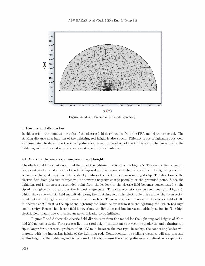
Figure 4 shows the meshing in the model geometry. The meshing was refined in the region between the
leader tip and lightning rod tip to increase the precision of the electric field distribution around the region
of interest. After the material and boundary condition settings were assigned in the model and meshed, the
model was solved for its electric field distribution. The height of the lightning rod was varied from 10 to 200
m to obtain the relation between the striking distance and lightning rod height. These heights were chosen to
compare with the result from the previous research in [27].
4087
ABU BAKAR et al./Turk J Elec Eng & Comp Sci
Figure 4. Mesh elements in the model geometry.
4. Results and discussion
In this section, the simulation results of the electric field distributions from the FEA model are presented. The
striking distance as a function of the lightning rod height is also shown. Different types of lightning rods were
also simulated to determine the striking distance. Finally, the effect of the tip radius of the curvature of the
lightning rod on the striking distance was studied in the simulation.
4.1. Striking distance as a function of rod height
The electric field distribution around the tip of the lightning rod is shown in Figure 5. The electric field strength
is concentrated around the tip of the lightning rod and decreases with the distance from the lightning rod tip.
A positive charge density from the leader tip induces the electric field surrounding its tip. The direction of the
electric field from positive charges will be towards negative charge particles or the grounded point. Since the
lightning rod is the nearest grounded point from the leader tip, the electric field becomes concentrated at the
tip of the lightning rod and has the highest magnitude. This characteristic can be seen clearly in Figure 6,
which shows the electric field magnitude along the lightning rod. The electric field is zero at the intersection
point between the lightning rod base and earth surface. There is a sudden increase in the electric field at 200
m because at 200 m it is the tip of the lightning rod while below 200 m it is the lightning rod, which has high
conductivity. Hence, the electric field is low along the lightning rod but increases suddenly at its tip. The high
electric field magnitude will cause an upward leader to be initiated.
Figures 7 and 8 show the electric field distribution from the model for the lightning rod heights of 20 m
and 200 m, respectively. For a greater lightning rod height, the distance between the leader tip and lightning rod
tip is larger for a potential gradient of 500 kV m−1 between the two tips. In reality, the connecting leader will
increase with the increasing height of the lightning rod. Consequently, the striking distance will also increase
as the height of the lightning rod is increased. This is because the striking distance is defined as a separation
4088

ABU BAKAR et al./Turk J Elec Eng & Comp Sci
between the tip of the lightning rod, where the connecting leader is initiated, and the tip of the downward
leader when the attachment is established between the connecting leader and the tip of the downward leader.
However, there is no significant difference in the way the electric field is distributed between the two lightning
rod heights.
Figure 5. Electric field distribution around the tip of the
lightning rod.
Figure 6. Electric field magnitude along the rod.
Figure 7. Electric potential distribution for a lightning rod height of 20 m.
Figure 9 shows the striking distance as a function of the lightning rod height for a rod radius of 0.01 m
from the model geometry that has been developed. The striking distance becomes larger when the rod height
increases. From Figure 9, using the curve fitting technique, a mathematical equation that can fit the data is
r = αhβ , (6)
4089

ABU BAKAR et al./Turk J Elec Eng & Comp Sci
Figure 8. Electric potential for a lightning rod height of 200 m.
where r is the striking distance, h is the height of the lightning rod, and α and β are constants. For the model
developed, α and β are equal to 11.16 and 0.5209, respectively.
The striking distance was determined by simulating the lightning attachment model under similar condi-
tions as described by Becerra and Cooray [27]. By assuming a lightning current magnitude of 15 kA, the striking
distance value was plotted as a function of lightning rod height, for different types of lightning inception model.
The models are inclusive of the Erickson, Rizk, Petrov, and Lalande model. As depicted in Figure 10, the
striking distance values obtained from the FEA simulation increase logarithmatically with respect to the height
of the rod. Furthermore, the FEA results demonstrate the same graph trend as compared with the existing
models. Hence, a good agreement with the results validates that the FEA model is adequate in determining
the striking distance as a function of lightning rod height.
0 10 20 30 40 50 60 70 80 90 10011012013014015016017018019020020
40
60
80
100
120
140
160
180
200
Height of rod (m)
Stri
kin
g d
ista
nce
(m
)
0 10 20 30 40 50 60 70 80 90 100110120130140 1501601701801902000
50
100
150
200
250
300
Height of Rod (m)
Str
ikin
g d
ista
nc
e (m
)
rizkcritical radius0.36critical radius 0.28petrovlalandecomsol
Figure 9. Striking distance as a function of lightning rod
height for 0.01 m rod radius using FEA model geometry.
Figure 10. Striking distance as a function of lightning
rod height for 0.01 m rod radius from previous models
and FEA model.
4090
ABU BAKAR et al./Turk J Elec Eng & Comp Sci
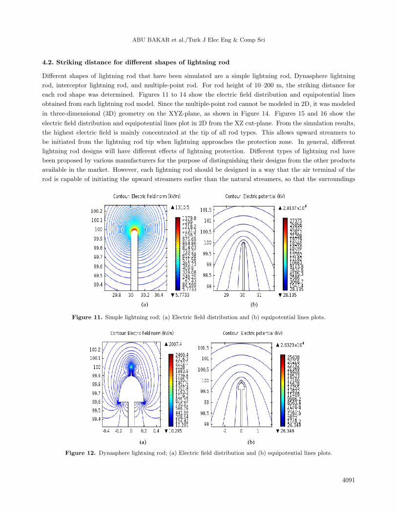
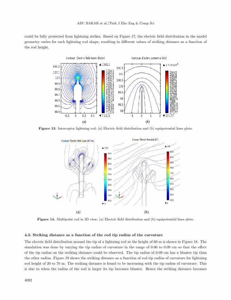
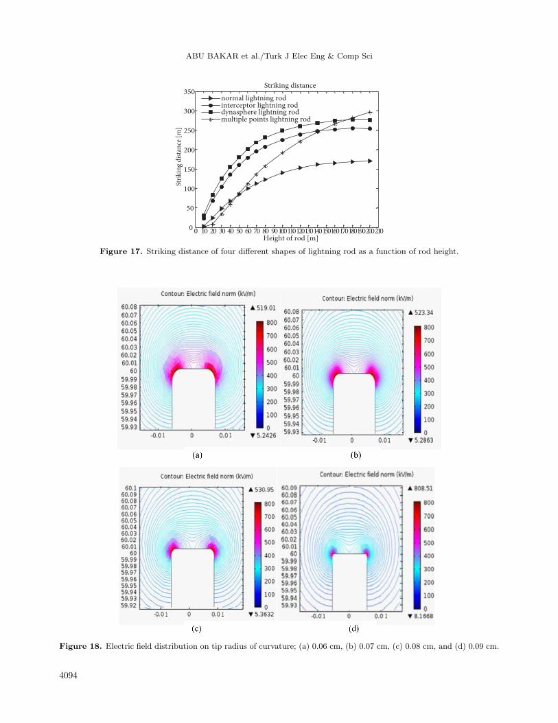
4.2. Striking distance for different shapes of lightning rod
Different shapes of lightning rod that have been simulated are a simple lightning rod, Dynasphere lightning
rod, interceptor lightning rod, and multiple-point rod. For rod height of 10–200 m, the striking distance for
each rod shape was determined. Figures 11 to 14 show the electric field distribution and equipotential lines
obtained from each lightning rod model. Since the multiple-point rod cannot be modeled in 2D, it was modeled
in three-dimensional (3D) geometry on the XYZ-plane, as shown in Figure 14. Figures 15 and 16 show the
electric field distribution and equipotential lines plot in 2D from the XZ cut-plane. From the simulation results,
the highest electric field is mainly concentrated at the tip of all rod types. This allows upward streamers to
be initiated from the lightning rod tip when lightning approaches the protection zone. In general, different
lightning rod designs will have different effects of lightning protection. Different types of lightning rod have
been proposed by various manufacturers for the purpose of distinguishing their designs from the other products
available in the market. However, each lightning rod should be designed in a way that the air terminal of the
rod is capable of initiating the upward streamers earlier than the natural streamers, so that the surroundings
Figure 11. Simple lightning rod; (a) Electric field distribution and (b) equipotential lines plots.
Figure 12. Dynasphere lightning rod; (a) Electric field distribution and (b) equipotential lines plots.
4091
ABU BAKAR et al./Turk J Elec Eng & Comp Sci
could be fully protected from lightning strikes. Based on Figure 17, the electric field distribution in the model
geometry varies for each lightning rod shape, resulting in different values of striking distance as a function of
the rod height.
Figure 13. Interceptor lightning rod; (a) Electric field distribution and (b) equipotential lines plots.
Figure 14. Multipoint rod in 3D view; (a) Electric field distribution and (b) equipotential lines plots.
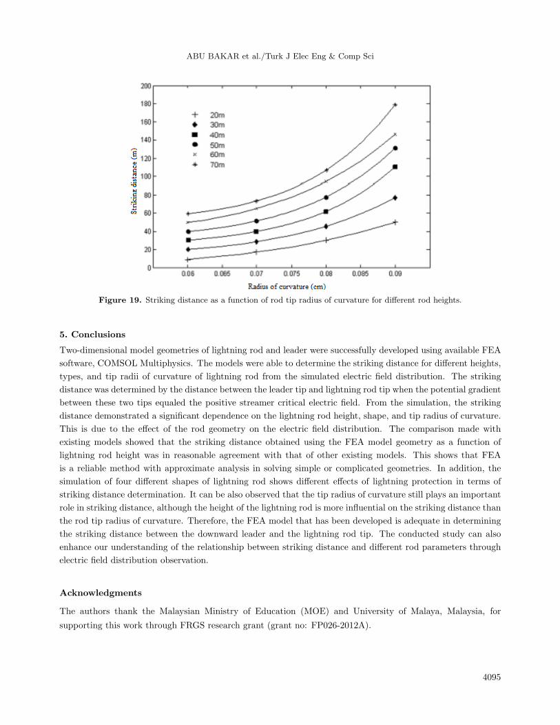
4.3. Striking distance as a function of the rod tip radius of the curvature
The electric field distribution around the tip of a lightning rod at the height of 60 m is shown in Figure 18. The
simulation was done by varying the tip radius of curvature in the range of 0.06 to 0.09 cm so that the effect
of the tip radius on the striking distance could be observed. The tip radius of 0.09 cm has a blunter tip than
the other radius. Figure 19 shows the striking distance as a function of rod tip radius of curvature for lightning
rod height of 20 to 70 m. The striking distance is found to be increasing with the tip radius of curvature. This
is due to when the radius of the rod is larger its tip becomes blunter. Hence the striking distance becomes
4092

ABU BAKAR et al./Turk J Elec Eng & Comp Sci
higher. The results also show that for certain radius of curvature the striking distance is larger with a higher
rod. Further validation of the simulated results has been made based on the publication by Moore et al. [28].
The published data proved that a blunt rod is a good strike receptor in lightning events. Due to its ability
to initiate the stable upward leaders earlier under the strong field, a longer striking distance will be produced.
This successfully validates the simulated results, in which a blunter rod yields greater striking distance, thus
improving the lightning protection. Furthermore, the simulated results prove that the tip radius of curvature
plays an important role in the striking distance determination. However, its influence on the striking distance
is not very significant as compared to the effect of the lightning rod’s height [29].
Figure 15. Multipoint rod in 2D view: (a) Electric field distribution on XZ cut-plane at y = –2.7 (b) Electric field
distribution on XZ cut-plane at y = 0 (c) Electric field distribution on XZ cut-plane at y = 2.7.
Figure 16. Multipoint rod in 2D view: (a) Equipotential lines plots on XZ cut-plane at y = –2.7 (b) Equipotential
lines plots on XZ cut-plane at y = 0 (c) Equipotential lines plots on XZ cut-plane at y = 2.7.
4093
ABU BAKAR et al./Turk J Elec Eng & Comp Sci
0 10 20 30 40 50 60 70 80 901001101201301401501601701801902002100
50
100
150
200
250
300
350
Height of rod [m]
Stri
kin
g d
ista
nce
[m
]
Striking distance
normal lightning rodinterceptor lightning roddynasphere lightning rodmultiple points lightning rod
Figure 17. Striking distance of four different shapes of lightning rod as a function of rod height.
Figure 18. Electric field distribution on tip radius of curvature; (a) 0.06 cm, (b) 0.07 cm, (c) 0.08 cm, and (d) 0.09 cm.
4094
ABU BAKAR et al./Turk J Elec Eng & Comp Sci
Figure 19. Striking distance as a function of rod tip radius of curvature for different rod heights.
5. Conclusions
Two-dimensional model geometries of lightning rod and leader were successfully developed using available FEA
software, COMSOL Multiphysics. The models were able to determine the striking distance for different heights,
types, and tip radii of curvature of lightning rod from the simulated electric field distribution. The striking
distance was determined by the distance between the leader tip and lightning rod tip when the potential gradient
between these two tips equaled the positive streamer critical electric field. From the simulation, the striking
distance demonstrated a significant dependence on the lightning rod height, shape, and tip radius of curvature.
This is due to the effect of the rod geometry on the electric field distribution. The comparison made with
existing models showed that the striking distance obtained using the FEA model geometry as a function of
lightning rod height was in reasonable agreement with that of other existing models. This shows that FEA
is a reliable method with approximate analysis in solving simple or complicated geometries. In addition, the
simulation of four different shapes of lightning rod shows different effects of lightning protection in terms of
striking distance determination. It can be also observed that the tip radius of curvature still plays an important
role in striking distance, although the height of the lightning rod is more influential on the striking distance than
the rod tip radius of curvature. Therefore, the FEA model that has been developed is adequate in determining
the striking distance between the downward leader and the lightning rod tip. The conducted study can also
enhance our understanding of the relationship between striking distance and different rod parameters through
electric field distribution observation.
Acknowledgments
The authors thank the Malaysian Ministry of Education (MOE) and University of Malaya, Malaysia, for
supporting this work through FRGS research grant (grant no: FP026-2012A).
4095

ABU BAKAR et al./Turk J Elec Eng & Comp Sci
References
[1] Hwang CC, Huang SR, Bor SS. Finite element modeling of lightning. In: IEEE Int Conf Energy Management and
Power Delivery (EMPD) 1995; 1: 298-301.
[2] Uman MA. The Lightning Discharge. New York, NY, USA: Dover Publications, 2001.
[3] Cooray V, Nucci CA, Rachidi F. On the possible variation of the lightning striking distance as defined in the IEC
lightning protection standard as a function of structure height. In: IEEE Int Conf Lightning Protection (ICLP)
2012; 1-5.
[4] Eriksson AJ. An improved electrogeometric model for transmission line shielding analysis. IEEE T Power Deliver
1987; 2: 871-886.
[5] Eriksson AJ. The incidence of lightning strikes to power lines. IEEE T Power Deliver 1987; 2: 859-870.
[6] Dellera L, Garbagnati E. Lightning stroke simulation by means of the leader progression model. I. Description of
the model and evaluation of exposure of free-standing structures. IEEE T Power Deliver 1990; 5: 2009-2022.
[7] Dellera L, Garbagnati E. Lightning stroke simulation by means of the leader progression model. II. Exposure and
shielding failure evaluation of overhead lines with assessment of application graphs. IEEE T Power Deliver 1990; 5:
2023-2029.
[8] D’Alessandro F. The use of ‘field intensification factors’ in calculations for lightning protection of structures. J
Electrostat 2003; 58: 17-43.
[9] Carrara G, Thione L. Switching surge strength of large air gaps: a physical approach. IEEE T Power Ap Syst 1976;
95: 512-524.
[10] Bernardi M, Dellera L, Garbagnati E, Sartorio G. Leader progression model of lightning: updating of the model
on the basis of recent test results. In: Proc 23rd Int Conf Lightning Protection (ICLP) 1996; Florence, Italy, pp.
399-407.
[11] Rizk FAM. A model for switching impulse leader inception and breakdown of long air-gaps. IEEE T Power Deliver
1989; 4: 596-606.
[12] Petrov NI, Waters RT. Determination of the striking distance of lightning to earthed structures. Proc R Soc Lon
Ser-A 1995; 450: 589-601.
[13] Lalande P. Study of the lightning stroke conditions on a grounded structure. Doctoral Thesis, a publication of Office
National d’Etudes et de Recherches Aerospatiales (ONERA), 1996.
[14] Rizk FAM. Modeling of lightning incidence to tall structures. I. Theory. IEEE T Power Deliver 1994; 9: 162-171.
[15] Dellera L, Garbagnati E, Bernardi M, Bondiou A, Cooray V, Gallimberti I, Pedersen A, Ruhling F. Lightning
exposure of structures and interception efficiency of air terminals. CIGRE Report Task Force 1997; 33.
[16] Goelian N, Lalande P, Bondiou-Clergerie A, Bacchiega GL, Gazzani A, Gallimberti I. A simplified model for the
simulation of positive-spark development in long air gaps. J Phys D Appl Phys 1999; 30: 2441.
[17] Poljak D, Brebbia CA. Indirect Galerkin–Bubnov boundary element method for solving integral equations in
electromagnetics. Eng Anal Bound Elem 2004; 28: 771-777.
[18] Abdel-Salam M, Al-Abdul-Latif US. Simulation of energized Franklin rods for lightning protection. IEEE T Ind
Appl 1997; 33: 651-659.
[19] Ait-Amar S, Berger G. Attractive radius of elevated building. In: Proc 28th Int Conf Lightning Protection 2006;
Kanazawa, Japan, 357-362.
[20] Becerra M, Cooray V, Hartono ZA. Identification of lightning vulnerability points on complex grounded structures.
J Electrostat 2007; 65: 562-570.
[21] Becerra M. On the simulation of the lightning strikes to complex grounded structures. In: Comsol Conference 2012.
[22] Cooray V, Rakov V, Theethayi N. The lightning striking distance - revisited. J Electrostat 2007; 65: 296-306.
4096
ABU BAKAR et al./Turk J Elec Eng & Comp Sci
[23] Les Renardieres Group. Research on long air gap discharges at Les Renardieres–1973 results. Electra, Paris 1974;
35: 49-156.
[24] Les Renardieres Group. Negative discharges in long air gaps at Les Renardieres-1978 results. Electra 1981; 74:
67-216.
[25] Cooray V, Becerra M. Lightning Protection. The Institution of Engineering and Technology, 2009.
[26] Cooray V, Rakov V, Theethayi N. The relationship between the leader charge and the return stroke current-Berger’s
data revisited. In: Proc Int Conf Lightning Protection 2004; Avignon, France.
[27] Becerra M, Cooray V. A simplified physical model to determine the lightning upward connecting leader inception.
IEEE T Power Deliver 2006; 21: 897-908.
[28] Moore CB, Aulich GD, Rison W. Measurements of lightning rod responses to nearby strikes. Geophys Res Lett
2000; 27: 1487-1490.
[29] D’Alessandro F. Striking distance factors and practical lightning rod installations: a quantitative study. J Electrostat
2003; 59: 25-41.
4097