determination of the tensions appearing in ceramic layer applied to the blades for aircraft engine-1
TRANSCRIPT

DETERMINATION OF THE TENSIONS APPEARING IN CERAMIC LAYER APPLIED TO THE BLADES FOR AIRCRAFT ENGINE
Geanina Laura Pintilei, Daniel Dragomir Stanciu, Ionut Vasile Crismaru, Gica Narcis Basescu, Sorin Claudiu Iacob Strugaru and Corneliu Munteanu*
Technical University “Gheorghe Asachi” of Iasi, Faculty of Mechanical Engineering, Iasi, Romania, [email protected]
Abstract: The achievement of the ceramic layer on the turbine blades for aircraft engine is now a usual method used for increasing the strength and durability of the blades. Turbine blades for aircraft engine are subdued, during functioning, to thermal and mechanical stresses, which can lead to their deterioration. One of the problems which appears to the ceramic coatings is the resistance of the layer deposited, to the tensions in the turbine blades under the action of the centrifugal force and force produced by the gas stream. In this paper is carried the analysis of these solicitations onto a layer of ceramic material deposited on the moving blades of aircraft engine Tumanski R13 which equips MIG 21. A calculation model was developed, using finite element analysis module, from the software CATIA V5R19. The calculation has taken into account/consideration the composed request due to the forces that are acting on blades. The resulting tension was determined on the basis of Von Mises’s equivalence theorem.
Keywords: finite element analysis, simulation, ZrO2/20%Y2O3
1.IntroductionOne way to improve the performance
for aircraft engines is increasing the temperature in the combustion chamber. By increasing the gases temperature in the turbine inlet it can significantly improve the performance and some other important functional parameters of gas turbo engines. [1]
The improvement of the temperature resistance of the aircraft engine elements can be obtained by application of a single ceramic thermal barrier coating.
The goal is to extend the lifetime of turbine blades by using a common, cheap and easily processed material, which coated with a thermal barrier by modern methods lead to improved thermo mechanical behavior of the blades, increasing their high temperature performance and prevents peeling. One of the problems which appear is the behavior of the ceramic coating layer due to the tensions that occur in the blades.
Static loading of the blades has two main components: the centrifugal force
which acts on the blade and the forces resulting from the action of the working fluid on the blades. [2]
Centrifugal force generates an axial load in the turbine blades. In case of twisted blades, the centrifugal forces produce normal and tangential tensions, which lead to an untwisting of the blade.
These two tensions are taken into consideration only for long blades, for shorter ones they are negligible.
The paper analysis the tensions distribution onto a layer of ceramic material deposited by atmospheric plasma spraying composed of ZrO2/20% Y2O3, on super alloy Inconel 625 blades of the aircraft turbo engine Tumanski R13, which equips the MIG 21. The gas turbine has two stages, with different rotation speeds. The analyze was made for the mobile blades of both stages.
2. Calculation model of the forces acting on the blade
The flow of the gas through the blades networks, determines on each blade

a force f, because of the different pressures between the suction side p1 and the pressure side p2 . The force f has two components coresponding to the tangential and axial directions: fu, fa. The model is presented in Fig.1, where w1, w2 are the relative velocities at the inlet and outlet sections.[3]
Figure.1. Calculation model of the forces acting on the blade
Based on the geometrical dimensions of the blades and the nozzles and on the results of the gasodynamic calculus of the stages, the values of force f and his components are presented in Tab.1
Table 1fu [N] fa [N] f [N]
Stage I 1003 585 1161Stage II 1097 1270 1678
The centrifugal force was default determined by the finite element analysis
3. Stress analysis using finite element method
The workflow sequence is roughly broken down into the following steps:
- Defining the geometry for the blade and the layer;
- Structural assembly;- Preprocessing;- Calculation of the stresses inside the
blade and the layer.
In figure 2 is represented a lower view of a mobile blade of the first stage and the TBC coating structure.
Figure.2. Turbine blade and the TBC coating structure.
3.1. Structural Assembly in CADThe first step was to create a CAD
model of the mobile blades of I an II stages and of the layers. This includes defining the geometry of the blades in different sections, establishing a structural assembly between the blade and the layer and defining the material for both the components.
The CAD model for the turbine blades and ceramic layers on the two turbine stages was done using the software CATIA V5 R19. For the base material from the turbine blades, we defined the properties of the Inconel 625 material and for the ceramic layer the properties of ZrO2/20% Y2O3.
The assembly of the two component parts, namely the ceramic layer and the base material, was made using a rigid connection condition between them.
3.2. PreprocessingThe finite element analysis was done
using the Generative Structural Analysis module of the CATIA V5 R19 program.
As boundary condition the blades were clamped on the lower surface. The loads that are applied to the blades are: centrifugal force due to the high rotational speeds of the blades and the force generated by the fluid flow through the network of blades.

The centrifugal force was modeled using the Rotation Force function, for which the body that is rotating is the assembly between the blade and the layer, the rotation axis is the axis of the shaft which was defined in the CAD model and the rotational speed is 11,200 turn/min for the first stage and 10,200 turn/min for the second.
The force produced by the gas flow is considered as a uniform distributed force on the pressure side of the blade and is introduced by it’s two components, namely the tangential force and the axial force, determined using the velocity triangles for the two stages. The finite elements used for the mesh are of tetrahedral parabolic type. In the mesh network composition can be noted that are 15577 elements with 5114 nodes (Figures 3.a. /3.b.)
Figure 3.a. Finite element mesh for first stage
Figure 3.b. Finite element mesh for second stage
4. Results In figure 4.a. / b. is presented the turbine blades from stage I, where it is possible to see that the zone with the highest stress is located at the base of blade and the maximum value of the stress is 251 MPa and that is present in the ceramic coating.
Figure 4.a Tension distribution of the blade from stage I with ceramic layer, suction side view
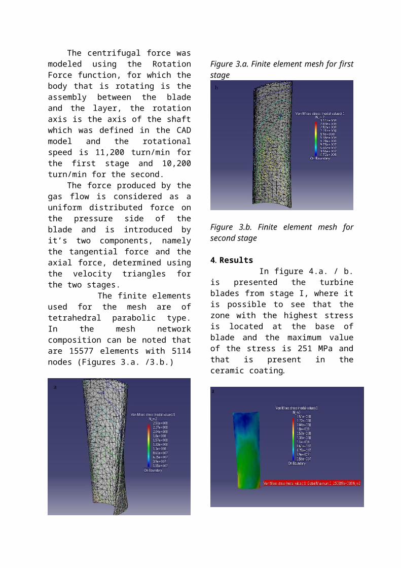
Figure 4.b Tension distribution of the blade from stage I with ceramic layer, pressure side view
In figure 5.a, b is presented the second stage of the blade. Here is observed that the zone with the highest stress is located on the central zone of the suction side of the blade and the maximum is 314 MPa. It can be observed that in the zone of the hole of the rigidization wire (Figure 6.b.) the value of the stress is higher because of the phenomenon of the tension concentrations.
Figure 5.a Tension distribution of the blade from stage II with ceramic layer, suction side view
Figure 5.b Tension distribution of the blade from stage II with ceramic layer, pressure side view
In both stages the distribution of tensions for blades with ceramic layer and without it is similar. The blades without ceramic layer of the first stage have the maximum stress value of 136 MPa and the second stage 356 MPa.
Figure 6.a Tension distribution of the blade from stage I without ceramic layer, suction side view

Figure 6.b Tension distribution of the blade from stage I without ceramic layer, pressure side view
Figure 7.a Tension distribution of the blade from stage II without ceramic layer, suction side view
Figure 7.b Tension distribution of the blade from stage II without ceramic layer, pressure side view
In table 2 are presented the maximum values of the stress for the blades with ceramic layer and for the blades without ceramic layer.
With ceramic layer [MPa]
Without ceramic layer [MPa]
Stage 1 251 136Stage 2 314 356
5. Conclusions From the presented values, we can conclude that the stress of the ceramic coating it’s less than the value of the admissible stress. For the ceramic material ZrO2/20% Y2O3 the value for the admissible stress is 380MPa. We can appreciate that:a) The blade of stage I with ceramic layer shows an increase in the maximum stress value at its base from the blade without the layer due to tangential shear stress occurring at the interface between the coating layer and the base material.b) In stage II can be seen a decrease in the maximum stress value of the blade with ceramic layer.c) To lower the maximum stress value for the blade from stage I with ceramic layer would be necessary to change the geometry of the section so the maximum stress value occurs inside the base material and doesn’t affect the ceramic layer.d) We conclude that there are situations when the geometry of the blade can influence negatively in terms of mechanical resistance the way that the layer interacts with the base material.e) It can be concluded that the ceramic layer does not influence decisively the distribution of tensions, but can improve the maximum stress that appears in the blades.
Acknowledgements

We thank SC AEROSTAR SA from Bacau for providing the super alloy substrates.
We acknowledge that this paper was realized with the support of EURODOC “Doctoral Scholarship for Research Performance at European level” project financed by the European Social Found and Rumanian Government.
References[1] C.C.Berndt et al., J.Thermal Spray Tech. 1(4) (1992).[2] C.Cantuniar, Turbomasini termice, Ed. Mirton Timisoara 2002[3] D. Ursescu and I. Tardea, Turbine cu abur si gaze, Ed. I.P. Iasi 1983.[4] S.Sampath and H.Herman, Microstructure Development in Plasma
Sprayed Coatings, Proceedings of International Thermal Spray Conference, Welding Inst., London Vol.1 (1989) P53.[5] Nicholas Curry, Nicolaie Markocsan, Xin-Hai Li, Aure´lien Tricoire, and Mitch Dorfman Next Generation Thermal Barrier Coatings for the Gas Turbine Industry (Submitted May 10, 2010; in revised form September 20, 2010).[6] R. Vassen, X. Cao, D. Stöver, Improvement of new thermal barrier coating systems using a layered or graded structure, 25th Annual Conference on Composites, Advanced Ceramics, Materials, and Structures: B: Ceramic Engineering and Science Proceedings, 22, 2008, pp. 435–442.
.