determination of the uls, for columns with small ... · a obtenção dos esforços internos...
TRANSCRIPT

© 2017 IBRACON
Volume 10, Number 2 (April 2017) p. 451 - 476 • ISSN 1983-4195http://dx.doi.org/10.1590/S1983-41952017000200009
Determination of the ULS, for columns with small dimensions, under biaxial bending and symmetrical fire conditions
Determinação do ELU, para pilares com pequenas dimensões, sob flexão composta oblíqua e incêndio simétrico
Abstract
Resumo
Obtaining internal load capacity, in reinforced concrete sections, at ambient temperature, under biaxial bending, is one of the most common tasks done by structural engineers, but not so common when the member is in fire situation.The intention of this paper is to show that is possible to correlate the ultimate limit state (ULS), in fire situation, with ULS at ambient temperature, for square cross sections under fire from all faces.To reach the purpose and give support to the numerical analysis of this article, a computer program, in Delphi language, called COL FIRE, is being developed by the authors.
Keywords: fire, columns, ultimate limit state, ULS, interaction diagram.
A obtenção dos esforços internos resistentes, em seções de concreto armado, à temperatura ambiente, sob flexão composta oblíqua, é uma das tarefas mais comuns realizadas por engenheiros de estruturas, mas não tão comum quando o elemento está submetido a ação de incêndio. O objetivo deste artigo é ilustrar que é possível correlacionar o estado-limite último (ELU), em situação de incêndio, ao ELU à temperatura am-biente, para seções quadradas sob incêndio em todas as faces.Para atingir o propósito e dar suporte à análise numérica deste artigo, um programa de computador, em linguagem Delphi, chamado COL FIRE, está em desenvolvido pelos autores.
Palavras-chave: incêndio, pilares, estado-limite último, ELU, diagrama de interação.
a Universidade de São Paulo, Escola Politécnica, Departamento de Engenharia de Estruturas e Geotécnica, São Paulo, SP, Brasil.
Received: 26 Jan 2016 • Accepted: 23 Jul 2016 • Available Online: 17 Apr 2017
M. CHEREM a
V. P. SILVA a

452 IBRACON Structures and Materials Journal • 2017 • vol. 10 • nº 2
Determination of the ULS, for columns with small dimensions, under biaxial bending and symmetrical fire conditions
1. Introduction
The achievement of ultimate limit state (ULS), in fire conditions, for uniaxial bending (UB), and for biaxial bending (BB), was already submitted by some authors such as, for instance, EL-FITIANY S.F; YOUSSEF M.A. [3]), MOREIRA A. M. M. M. [8], LAW A.; GIL-LIE M. [7] and RODRIGUEZ J.; ARISTIZABAL-OCHOA J. D. [9]. Such analysis, however, is relatively complex and impossible to be achieved without a specific fire analysis computer program.There are yet simplified calculation methods, such as, for instance, 500°C Isotherm Method, shown in EN 1992-1-2 [4], however, such methods also rely on the thermal analysis, which many times is not available to the structure engineers in the calculation offices.In all publications researched, national or international, none was found which correlates results calculated to the fire conditions to the ones found at ambient temperature. The authors purpose is showing that it is possible to develop a simplified method to assess the ulti-mate limit state (ULS) in fire conditions, without any thermal analy-sis or extremely sophisticated computer code, based only on the ultimate limit state (ULS), achieved at ambient temperature, which assessment has already been widespread in the technical means.The choice for small dimension square sections has as main pur-pose being the basis to assess columns found in industries, ware-houses and small household buildings. It can also be understood as starting point for this research progress for column sections with dif-ferent shapes and dimensions to be performed in upcoming works.
2. Fire analysis with advanced calculation methods
Advanced calculation methods shall provide a realistic analysis of structures exposed to fire. They shall be based on fundamental physi-cal behaviour leading to a reliable approximation of the expected be-haviour of the relevant structural component under fire conditions.Advanced calculation methods should include calculation models for the determination of:a) the development and distribution of the temperature within
structural members (thermal response model);
b) the mechanical behavior of the structure or of any part of it (me-chanical response model).
Advanced calculation methods may be used in association with any heating curve provided that the material properties are known for the relevant temperature range and the relevant rate of heating.Advanced calculation methods may be used with any type of cross section.
2.1 The temperature field
In an analysis of a plane cross section, in any analysis which in-volves fire situation, is to establish the fire curve (time-tempera-ture) which the structural member will be submitted and which are the faces of the cross section that will be submitted to fire situation.It is used, for this proposal, the ISO – 834 curve, also known as standard temperature-time curve.With the time-temperature curve established and all (four) faces under fire situation, it is determined the temperature ‘θi’ of each point of the cross section, in each instant of time ‘t’ desired. For this, it is necessary to resort to a numerical analysis, based on the finite element method applied to heat transfer. In this paper, this stage counts on developed by swede Dr. Yngve. Anderberg [5]. An example of the results can be visualized in Figure 1.The SuperTempcalc is a computer program of thermal analysis, bi-dimensional, non- linear, in transient regimes, that incorporates material thermal properties, which are functions of temperature in differential equations of heat transfer. The radiation and convection heat in the boundary of the element can be modeled as function of the time. The computer program was certified with innumerous experimental results since 1985 and its reliability is largely known, being used to development of the European standard [4].The field of temperatures is the name given to the set of distinct values of temperatures associated to each point of the cross sec-tion in a certain instant of time ‘t’.Usually, in reinforced concrete structures, to the analysis of heat transfer using finite element method, it is assumed that the tempera-ture of each reinforcing bar ‘θbi’ is the same of the temperature ‘θi’ obtained at the position of its geometrical center in the cross section.2.2 Concrete properties under fire situation
Figure 1Results of computer program SuperTempcalc [5], for a square cross section 30x30 cm, in some times of fire situation
453IBRACON Structures and Materials Journal • 2017 • vol. 10 • nº 2
M. CHEREM | V. P. SILVA
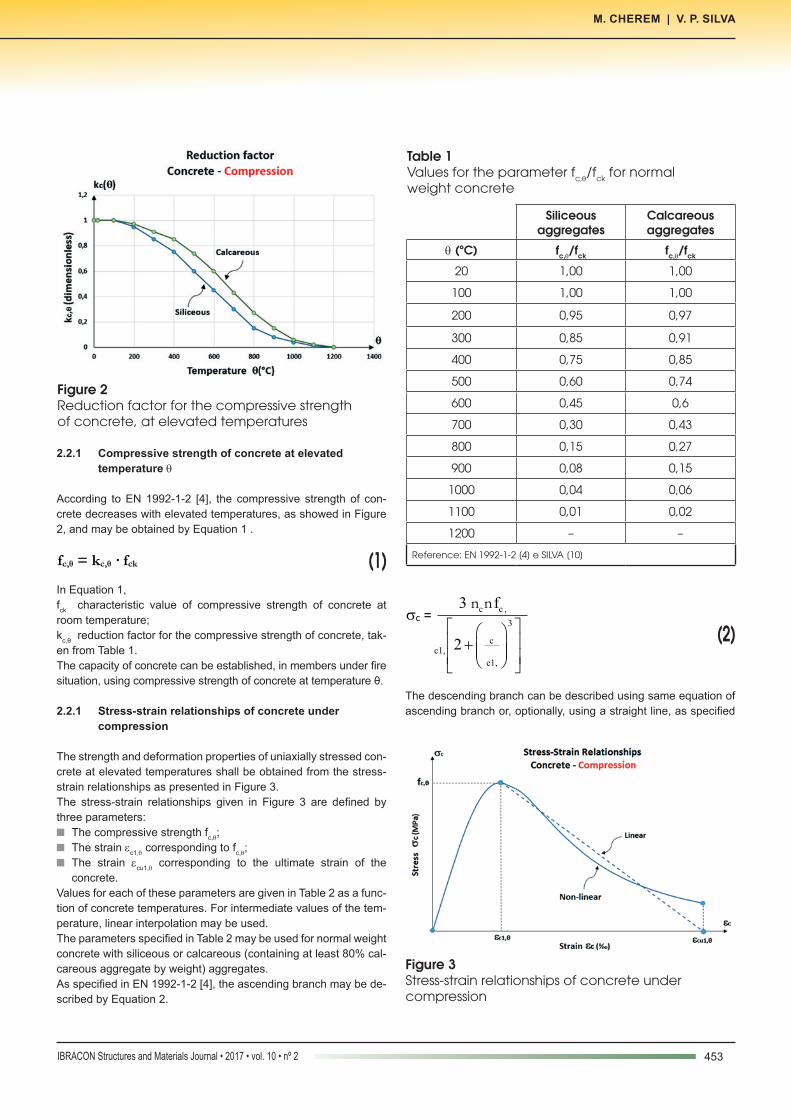
2.2.1 Compressive strength of concrete at elevated temperature θ
According to EN 1992-1-2 [4], the compressive strength of con-crete decreases with elevated temperatures, as showed in Figure 2, and may be obtained by Equation 1 .
(1)fc,θ = kc,θ · fck
In Equation 1, fck characteristic value of compressive strength of concrete at room temperature;kc,θ reduction factor for the compressive strength of concrete, tak-en from Table 1.The capacity of concrete can be established, in members under fire situation, using compressive strength of concrete at temperature θ.
2.2.1 Stress-strain relationships of concrete under compression
The strength and deformation properties of uniaxially stressed con-crete at elevated temperatures shall be obtained from the stress-strain relationships as presented in Figure 3.The stress-strain relationships given in Figure 3 are defined by three parameters:n The compressive strength fc,θ;n The strain εc1,θ corresponding to fc,θ;n The strain εcu1,θ corresponding to the ultimate strain of the
concrete.Values for each of these parameters are given in Table 2 as a func-tion of concrete temperatures. For intermediate values of the tem-perature, linear interpolation may be used.The parameters specified in Table 2 may be used for normal weight concrete with siliceous or calcareous (containing at least 80% cal-careous aggregate by weight) aggregates.As specified in EN 1992-1-2 [4], the ascending branch may be de-scribed by Equation 2.
(2)sc =
3
cc1,
c1,
2é ùæ öê ú+ ç ÷ç ÷ê úè øë û
c c ,3 fn n
The descending branch can be described using same equation of ascending branch or, optionally, using a straight line, as specified
Figure 2Reduction factor for the compressive strength of concrete, at elevated temperatures
Table 1Values for the parameter fc,θ/fck for normal weight concrete
Siliceous aggregates
Calcareous aggregates
θ (ºC) fc,θ/fck fc,θ/fck
20 1,00 1,00
100 1,00 1,00
200 0,95 0,97
300 0,85 0,91
400 0,75 0,85
500 0,60 0,74
600 0,45 0,6
700 0,30 0,43
800 0,15 0,27
900 0,08 0,15
1000 0,04 0,06
1100 0,01 0,02
1200 – –
Reference: EN 1992-1-2 [4] e SILVA [10]
Figure 3Stress-strain relationships of concrete under compression

454 IBRACON Structures and Materials Journal • 2017 • vol. 10 • nº 2
Determination of the ULS, for columns with small dimensions, under biaxial bending and symmetrical fire conditions
in the EN 1992-1-2 [4], by using equations 3 and 4.
(3)Non-linear:
c c ,3 fn nsc =
3
cc1,
c1,
2é ùæ öê ú+ ç ÷ç ÷ê úè øë û
(4)Linear: sc = ( )
cu1, c
cu1, c1,
-
- · fc,q
According to EN 1992-1-2 [4], possible strength gain of concrete in the cooling phase should not be taken into account.
2.3 Reinforced steel properties under fire situation
2.3.1 Strength of reinforced steel at elevated temperature θ
According to EN 1992-1-2 [4], the strength of reinforcing steel de-creases with elevated temperatures, as showed in Figure 4, and may be obtained by Equation 5.
(5)fy,θ = ks,θ · fyk
In the Equation 5,fyk characteristic strength of reinforcing steel at room temperature
ks,θ reduction factor for the strength of reinforcing steel, taken from Table 3.n continuous line: ks,θ applicable when εsi ≥ 2%, usually tension
reinforcement of beams, slabs or rods;n dashed line: ks,θ applicable when εsi < 2%, usually compressive
reinforcement of columns, beams or slabs.Reference: ABNT NBR 15200 [2], EN 1992-1-2 [4] e SILVA [10].
Table 2Parameters for stress-strain relationships of concrete under compression
θ (ºC) εc1,θ (‰) εcu1,θ (‰)
20 2,5 20
100 4,0 22,5
200 5,5 25
300 7,0 27,5
400 10 30
500 15 32,5
600 25 35
700 25 37,5
800 25 40
900 25 42,5
1000 25 45
1100 25 47,5
1200 – –
Reference: EN 1992-1-2 [4] e SILVA [10]
Figure 4Reduction factor for the strength of reinforcing steel, at elevated temperatures
Table 3Values for the parameter fy,θ/fyk for reinforcing steel
fy,θ/fyk
Tension Compression
θ (ºC) CA-50 CA-60 CA-50 or CA-60
20 1,00 1,00 1,00
100 1,00 1,00 1,00
200 1,00 1,00 0,89
300 1,00 1,00 0,78
400 1,00 0,94 0,67
500 0,78 0,67 0,56
600 0,47 0,40 0,33
700 0,23 0,12 0,10
800 0,11 0,11 0,08
900 0,06 0,08 0,06
1000 0,04 0,05 0,04
1100 0,02 0,03 0,02
1200 0,00 0,00 0,00
Reference: ABNT NBR 15200 [2], EN 1992-1-2 [4] e SILVA [10]

455IBRACON Structures and Materials Journal • 2017 • vol. 10 • nº 2
M. CHEREM | V. P. SILVA
2.3.2 Modulus of elasticity at elevated temperature θ
According to EN 1992-1-2 [4], the modulus of elasticity of rein-forcing steel decreases with elevated temperatures, as showed in Figure 5, and may be obtained by Equation 6.
(6)Es,θ = ksE,θ · Es
In the Equation 6,Es modulus of elasticity of reinforcing steel at room ambient,
ksE,θ reduction factor for the modulus of elasticity of reinforcing steel, taken from Table 4.
2.3.3 Stress-Strain relationships at elevated temperature θ
The properties of stress-strain relationships of reinforcing steel at elevated temperature should be obtained by stress-strain relation-ships given in Figure 6.The stress-strain relationships given in Figure 6 are defined by four parameters:n The strain εsp,θ corresponding to the value of stress fsp,θ (propor-
tional limit);n The strain εsy,θ corresponding to the value of stress fsy,θ (yield
strength);n The strain εst,θ corresponding to the value of stress fsy,θ (end of
plastic landing);n The strain εsu,θ corresponding to the ultimate strain of reinforcing
steel.As exposed in EN 1992-1-2 [4], the four different branches of the stress-strain relationships can be described by Equations 7 to 10.
(7)ss = Es,q · es
(8)ss = fsp,q – c + ( )22
sy,
ba
a
æ ö- -ç ÷
è øn
(9)ss = fsy,q
(10)ss = ( )
su, s
su, st,
-
- · fsy,q
In the Equation 8, the values of the functions a, b e c are given by equations 11 to 13.
(11)c = ( )
( ) ( )
2
sy, sp,
sy, sp, s, sy, sp,
f f
E 2 f f
-
- - -
Figure 5Reduction factor for the modulus of elasticity of reinforced steel at elevated temperatures
Table 4Values for the parameter ES,θ/ES for reinforcing steel
Es,θ/Es
θ (ºC) CA-50 CA-60
20 1,00 1,00
100 1,00 1,00
200 0,90 0,87
300 0,80 0,72
400 0,70 0,56
500 0,60 0,40
600 0,31 0,24
700 0,13 0,08
800 0,09 0,06
900 0,07 0,05
1000 0,04 0,03
1100 0,02 0,02
1200 0,00 0,00
Reference: ABNT NBR 15200 [2], EN 1992-1-2 [4] e SILVA [10]
Figure 6Stress-strain relationships for reinforcing steel

456 IBRACON Structures and Materials Journal • 2017 • vol. 10 • nº 2
Determination of the ULS, for columns with small dimensions, under biaxial bending and symmetrical fire conditions
(12)a = ( )sy, sp, sy, sp,
s,
E
æ ö- - +ç ÷ç ÷
è ø
c
(13)b = ( ) 2sy, sp, s,c E c- +
2.4 The internal loads
The trio of internal loads (N, Mx, My) is obtained by integration of stress values over the cross section, recollecting an observation that, wisely, the stresses are functions of the strains which, in turn, are functions of the temperatures which, again, are functions of time ‘t’.
(14)N = ( )ci, ici,tå · Aci + ( )si, isi,
tå · Asi
(15)Mx = – ( )ci, ici,tå · yci · Aci – ( )si, isi,
tå · ysi · Asi
(16)My = ( )ci, ici,tå · xci · Aci + ( )si, isi,
tå · xsi · Asi
2.5 The universe of possible results – Interaction surface
To determine the trio of internal loads (N, Mx, My) of a cross section,
in a specific time ‘t’ of fire situation, is necessary to impose three parameters for the cross section: the inclination of neutral axis (α), the curvature of the cross section (ρ) and the strain of the geometri-cal center (εcg), according to illustrated in Figure 7.It is worthwhile to note that the imposition that any three values (α, ρ, εcg) corresponds to a unique and exclusive trio of internal loads (N, Mx e My). On the other hand, it is practically impossible to determine values of curvature and strain of geometrical center that lead to ultimate limit state (ULS).In the fire analysis, all values are variables, functions of tem-perature, turning impossible to determine the exact values. The proposal, in this case, is to make a variation of the mentioned parameters until sufficient large values, this way, the ultimate limit state will appear naturally.n Inclination of neutral axis (α): varies from 0 to 360º;n Cross Section curvature (ρ): 0 ≤ ρ ≤ ρmáx ;n Strain of the geometric center (εcg): εcg,mín ≤ εcg ≤ εcg,máx .The universe of possible results can be illustrated in Figure 8.
2.6 Axial force limits
For a rectangular reinforced concrete cross section, the axial load capacities (NRd) and, obviously, the axial internal load (NSd) that can be applied, at room temperature, are in the range determined by Equations 17 and 18.
(17) NRd,min = – As · fyd
Figure 7Parameters which defines the trio of internal loads (N, Mx e My)
Figure 8Universe of results ranging the three parameters (α, ρ and εcg)

457IBRACON Structures and Materials Journal • 2017 • vol. 10 • nº 2
M. CHEREM | V. P. SILVA
(18) NRd,max = Ac · fcd + As · ss,ec2
In Equation 17,As total area of reinforced steel in the cross sectionfyd design strength of the steel reinforcement, at room tempera-tureIn Equation 18,Ac concrete area in the cross section fcd design concrete compressive strength, at room temperatureσs,εc2 compressive stress of reinforced steel, corresponding to the compressive strain εc1 of concrete, at room temperatureThe insertion of these two values in the interaction surface repre-sents two restraining planes, illustrated in Figure 9.In usual designs of structures, the axial internal load (NSd) is always a ratio of axial load capacity (NRd), because if NSd was numerically equal to NRd, the cross section would be at the limit of capacity, in a pure compression, without the possibility of si-multaneously bending moments.
2.7 The interaction diagram for a specific axial internal load
Determinado o universo de possibilidades, conforme descrito no item anterior, para a força normal de interesse, passa-se um plano horizontal, destacando os valores extremos nesse plano, valores que correspondem exatamente ao estado-limite último (ELU) em incêndio, naquele instante de tempo considerado, conforme exibido na Figure 10.
Taking as numerical example a 30x30 cm cross section, compres-sive strength of concrete fck= 30 MPa, 8 reinforcing bars of φ10 mm of CA-50, axial internal load NSd = 761,22 kN (40% of NRd.,máx), the computer program developed by authors provides the curves at the ultimate limit state illustrated in Figure 11.Observing the interaction diagrams at ultimate limit states in fire analysis, it is clearly noticed that, with the progress of fire situation, the internal load capacity reduction respects some proportionality.
3. Results and discussions
In this item the results will be added as figures and tables. The results will be discussed in order to ground the considerations and conclusions the article provides.
3.1 Fire analysis correlation with the ambient temperature
It is noted, by the previous item description, that the fire conditions analysis is extremely demanding, and it is practically impossible to achieve it without, at least, two computer programs duly prepared to the numerical analysis: SuperTempcalc [5] (for heat transfer) and the program developed by the authors to this article (for the internal loads).In an attempt to make the approach simpler, it has been decided to propose a correlation between the ultimate limit state under fire situation with the ultimate limit state analysis performed at ambient temperature, as provided by standard ABNT NBR 6118:2014, a widely known process by the structure engineers.Considering as numeric example the 30x30 cm cross section, the
Figure 9Universe of cases restrained by axial force limits
Figure 10Section cut in a specific axial load

458 IBRACON Structures and Materials Journal • 2017 • vol. 10 • nº 2
Determination of the ULS, for columns with small dimensions, under biaxial bending and symmetrical fire conditions
same previously used, as the interaction diagram is inserted to the last limit state at ambient temperature over the fire analysis interac-tion diagrams, what happens in Figure 12 is seen.It is possible to note that the ultimate limit state curve at ambient temperature, despite being assessed regardless of the fire analy-sis, assures the cross section some load capacity, concerning the requesting internal loads, which, in the instance provided, corre-sponds visually to approximately 60 minutes of fire resistance. It is obvious that this is not a fixed value to cross-sections, as such time varies in cross section geometry, reinforcement quantity and axial load value functions.The fact that the cross section, designed to the ultimate limit state at room temperature, assures a specific resistant fire time is a cross section inherent property, even if the structure engineer did not intend to promote such property.The curve associated at ambient temperature, however, keeps ap-
proximately the same curve geometric shape for fire conditions. Such correspondence suggested to the authors that it would be possible to develop an approximate method that can correlate any fire ultimate limit state, at any time, with the ultimate state limit achieved at ambient temperature, using for that matter only one reducing factor which is simply a scale reduction.
3.2 Cross-sections studied
As mentioned in the article´s introduction, the analysis purpose is being the basis for small dimension columns, which can be used in industries, warehouses and small size buildings. In order to create cross sections, some parameters were used:n Exposure Class II (EC II): coverage c = 3 cm;n Stirrups: φt ≤ 6.3 mm;n The exposure class choice purpose is studying the column
Figure 11Evolution of interaction diagram at ULS for different fire times

459IBRACON Structures and Materials Journal • 2017 • vol. 10 • nº 2
M. CHEREM | V. P. SILVA
sections in urban environment. With widespread width, the col-umn shear force is not significant, so that the stirrups in these cross sections that do not require large diameters, thus, the φt ≤ 6.3 cm hypothesis cover a large part of the current columns.
According to Table 5, it can be noticed that such study covers 14 different cross sections. All cross sections have been subjected to:n Axial loads (NSd): varying from 0 to NRd,max, with interval of 0.10 NRd,max ;n Fire resistance (FR): varying from 0 to 180 min, with interval of 30 min.The conclusion is, thus, that each cross-section will be subjected to 11 ordinary forces and 7 different fire times, totaling 77 study cases by cross-section, totaling 1078 analysis for this article.
3.3 Reducer factor ‘fr’ to the ultimate limit state at ambient temperature
As above mentioned, a reducer factor ‘fr’ is created, which enables
a fire conditions analysis, from, only, the interaction diagram of the ultimate limit state at ambient temperature, without thermal analy-sis need.After processing 1078 cases, for each value three cases, the cor-responding reducer factors ‘fr’ were registered, concerning the ul-timate limit state at ambient temperature. After the registrations, regressions were performed, using the program LabFit [11], sepa-rating the cross section by dimensions, which results are present-ed in Table 6.Only the fire time ‘t’’ was chosen, as independent variable.The statistic measure called ‘qui-square reduced’ is a regression quality indicative performed which, as it is closer to zero, it proves the presented equation reliability.It was noticed that, for axial load ratios rN = Rd
Rd,máx
NN
over 0.7, the regression turned into poor quality, not leading to good results,
Figure 12ULS interaction diagram insertion, at ambient temperature, over the ULS interaction diagrams, in fire analysis

460 IBRACON Structures and Materials Journal • 2017 • vol. 10 • nº 2
Determination of the ULS, for columns with small dimensions, under biaxial bending and symmetrical fire conditions
Table 5Cross sections studied
Cross sectionDistance from face to the geometric
center of reinforcementc1 = c +φt + φL/2 (cm)
Longitudinal reinforcementφL
4.5
4 φ 10mm
4 φ 12.5mm
4 φ 16mm
4.5
4 φ 10mm
4 φ 12.5mm
4 φ 16mm
5.0 4 φ 20mm
4.5
8 φ 10mm
8 φ 12.5mm
8 φ 16mm
4.5
8 φ 10mm
8 φ 12.5mm
8 φ 16mm
5.0 8 φ 20mm
Table 6Results to factor ‘fr’
Cross section Reducer factor(30 min ≤ t ≤ 180min and rN ≤ 0,7 )
Qui-square reducedc²red
fr = 3.615 – 0.710 ln t 0.02
fr = 4.016 – 0.757 ln t 0.06
fr = 4.053 – 0.736 ln t 0.07

461IBRACON Structures and Materials Journal • 2017 • vol. 10 • nº 2
M. CHEREM | V. P. SILVA
thus it was chosen, at this time, to exclude such data, limiting the method presented herein.Taking as example the cross sections of 20x20 cm dimensions, the graph shown in Figure 13 shows the function ‘fr’ against the values achieved by the program developed by the authors.
3.4 Reducer factor ‘fr’ application example
At first, the ultimate limit state at room temperature analysis is performed, as provided by standard ABNT NBR 6118:2014, and to achieve the fire ultimate limit state, at a specific fire resistance time ´t´, the reducer factor ‘fr’ is applied to the values found. The procedure´s advantage is preventing any fire analysis and achiev-ing approximate results.It is worth noting that, at ambient temperature, according to stan-dard ABNT NBR 6118:2014, the concrete tension distribution is performed as per the parabola-rectangle diagram, with peak
stress equals to 0.85 fcd, however, as alternative, if the uniform tension block is used, with neutral axis position 80% depth, the tension must be taken as 0.765 fcd, as the section width, mea-sured in parallel to the neutral line, decreases from this one to the compressed edge.Taking as numeric example a 30x30 cm section, characteristic re-sistance to concrete compression fck = 30 Mpa, with 8 reinforcing bars of φ10mm of CA-50, and the method proposed in this article is applied to an axial load NSd = 761.22 kN (40% of NRd.,max). In this case, to achieve the fire conditions ultimate limit state, for a fire exposure time of 90 min, in the four cross section faces, it is enough to apply the reducer factor to the ultimate limit state achieved at ambient temperature, according to standard ABNT NBR 6118:2014. The results are found in Table 7.fr = fr = 4.053 – 0.736 ln 90 = 0.74The corresponding interaction diagram to fire ultimate limit state, for a fire resistance time (FRT) of 90 minutes, achieved from the diagram at ambient temperature, with reducer factor application, was compared to the corresponding to fire analysis, using the ad-vanced calculation methods, according to Figure 14.Note, in Figure 14, that the fire ultimate limit state curve, achieved by the simplified method proposed herein, with the reducer factor application, the curve achieved remains internal as the fire analy-sis is performed with the advanced calculation method, by means of the program developed by the authors, considering the several variables involved.
4. Conclusions
It was proposed, in this article, a simplified procedure that enables inferring the internal load capacity for columns, concerning the re-questing internal loads, for biaxial bending, in symmetric fire condi-tions, within specific dimension and load limits, from values found at ambient temperature.For each fire resistance time, the internal load capacity reduction
Figure 13Function illustration that describes the reducer factor against the results achieved
Table 7ULS assessment on fire from ULS at ambient temperature
Ambient temperature Fire t = 90 min (fr =0.74)
α (º) MRxd (kN∙m) MRyd (kN∙m) MRxd,fi (kN∙m) MRyd,fi (kN∙m)
0 -72.28 0.00 -53.48 0.00
10 -69.59 -8.78 -51.50 -6.50
20 -64.88 -18.21 -48.01 -13.47
30 -58.17 -28.08 -43.05 -20.78
40 -49.27 -38.77 -36.46 -28.69
50 -38.77 -49.27 -28.69 -36.46
60 -28.08 -58.17 -20.78 -43.05
70 -18.21 -64.88 -13.47 -48.01
80 -8.78 -69.59 -6.50 -51.50
90 0.00 -72.28 0.00 -53.48

462 IBRACON Structures and Materials Journal • 2017 • vol. 10 • nº 2
Determination of the ULS, for columns with small dimensions, under biaxial bending and symmetrical fire conditions
concerning the ambient temperature complies with some propor-tionality, what enabled creating a reduction factor ‘fr’ which, applied to the results found at ambient temperature, provides the fire con-ditions results.The procedure proposed in this article enables, in simplified form, to assess the results related to the internal load capacity, in fire conditions, dismissing the thermal analysis.The method proposed herein can only be applied within the limits presented in the article. Studies to expand such limits are in prog-ress.
5. Acknowledgements
The authors wish to thank CAPES - Higher Education Personnel Improvement Coordination, CNPq - National Scientific Research
and Development Council, and FAPESP - Research Support Foundation of the State of São Paulo.
6. Bibliographic references
[1] ASSOCIAÇÃO BRASILEIRA DE NORMAS TÉCNICAS. Projeto de Estruturas de Concreto – Procedimento. NBR 6118, Rio de Janeiro, 2014.
[2] ASSOCIAÇÃO BRASILEIRA DE NORMAS TÉCNICAS. Projeto de estruturas de concreto em situação de incêndio. NBR 15200, Rio de Janeiro, 2012.
[3] EL-FITIANY, S.F.; YOUSSEF, M.A. Interaction diagrams for fire-exposed reinforced concrete sections. Journal: Engi-neering Structures, v. 70, p. 246–259, July 2014.
[4] EUROPEAN COMMITTEE FOR STANDARDIZATION.
Figure 14Achieved result comparison, by the approximate method, using the reducer factor ‘fr’, with the result achieved by fire advanced analysis

463IBRACON Structures and Materials Journal • 2017 • vol. 10 • nº 2
M. CHEREM | V. P. SILVA
Eurocode 2: Design of concrete structures – part 1.2 Gen-eral rules – structural fire design. EN 1992-1-2. Brussels: CEN, 2004.
[5] FIRE SAFETY DESIGN (FSD). TCD 5.0 User’s manual. Lund: Fire Safety Design AB, 2007
[6] INTERNATIONAL ORGANIZATION FOR STANDARDIZA-TION. ISO 834: Fire-resistance tests: elements of building construction - part 1.1: general requirements for fire resis-tance testing. Geneva, 1999. 25 p. (Revision of first edition ISO 834:1975).
[7] LAW, A.; GILLIE, M. Interaction Diagrams for Ambient and Heated Concrete Sections. Journal: Engineering Structures, v. 32, n. 6, p. 1641-1649, 2010.
[8] MOREIRA, A. M. M. M. Verificação de seções retangulares de concreto armado submetidas à flexão oblíqua composta em situação de incêndio. Universidade Federal de Minas Gerais, Belo Horizonte, 2013.
[9] RODRIGUEZ, J.; ARISTIZABAL-OCHOA, J. D. Biaxial Inter-action Diagrams for Short RC Columns of Any Cross Sec-tion. Journal of Structural Engineering, v. 125, n. 6, p. 672-683, June 1999.
[10] SILVA, V. P. Projeto de Estruturas de Concreto em Situação de Incêndio. São Paulo: Editora Blucher, 2012.
[11] SILVA, W.P.; SILVA, C.M.D.P.S. LAB Fit Curve Fitting Soft-ware (Nonlinear Regression and Treatment of Data Pro-gram) v 7.2.49 (1999-2016).