determining the optical constants of euv reflectors jedediah johnson dr. david allred
TRANSCRIPT
Determining the Optical Determining the Optical Constants of EUV Constants of EUV
ReflectorsReflectorsJedediah JohnsonJedediah Johnson
Dr. David AllredDr. David Allred
Talk OutlineTalk Outline
Background physics/applicationsBackground physics/applications
Project MotivationProject Motivation
Previous measurement techniquesPrevious measurement techniques
Current sputtered diode researchCurrent sputtered diode research
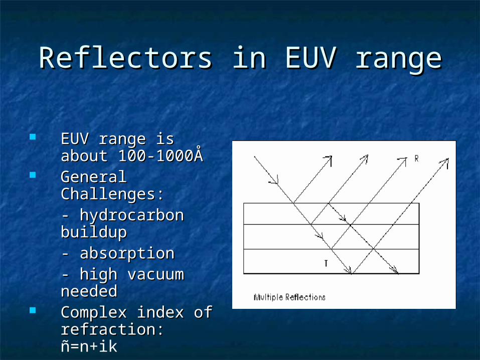
Reflectors in EUV rangeReflectors in EUV range
EUV range is about EUV range is about 100-1000Å100-1000Å
General Challenges:General Challenges:- hydrocarbon - hydrocarbon buildupbuildup- absorption- absorption- high vacuum - high vacuum neededneeded
Complex index of Complex index of refraction: refraction: ñ=n+ik
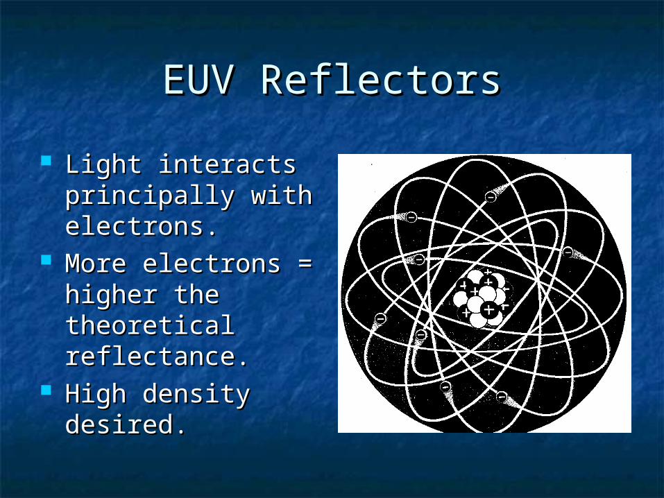
EUV ReflectorsEUV Reflectors
Light interacts Light interacts principally with principally with electrons.electrons.
More electrons = More electrons = higher the higher the theoretical theoretical reflectance. reflectance.
High density High density desired.desired.
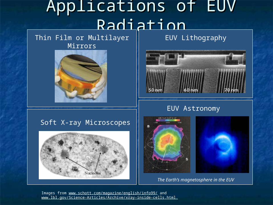
Applications of EUV RadiationApplications of EUV RadiationEUV Lithography
Images from www.schott.com/magazine/english/info99/ and www.lbl.gov/Science-Articles/Archive/xray-inside-cells.html.
Soft X-ray Microscopes
Thin Film or Multilayer Mirrors
EUV Astronomy
The Earth’s magnetosphere in the EUV
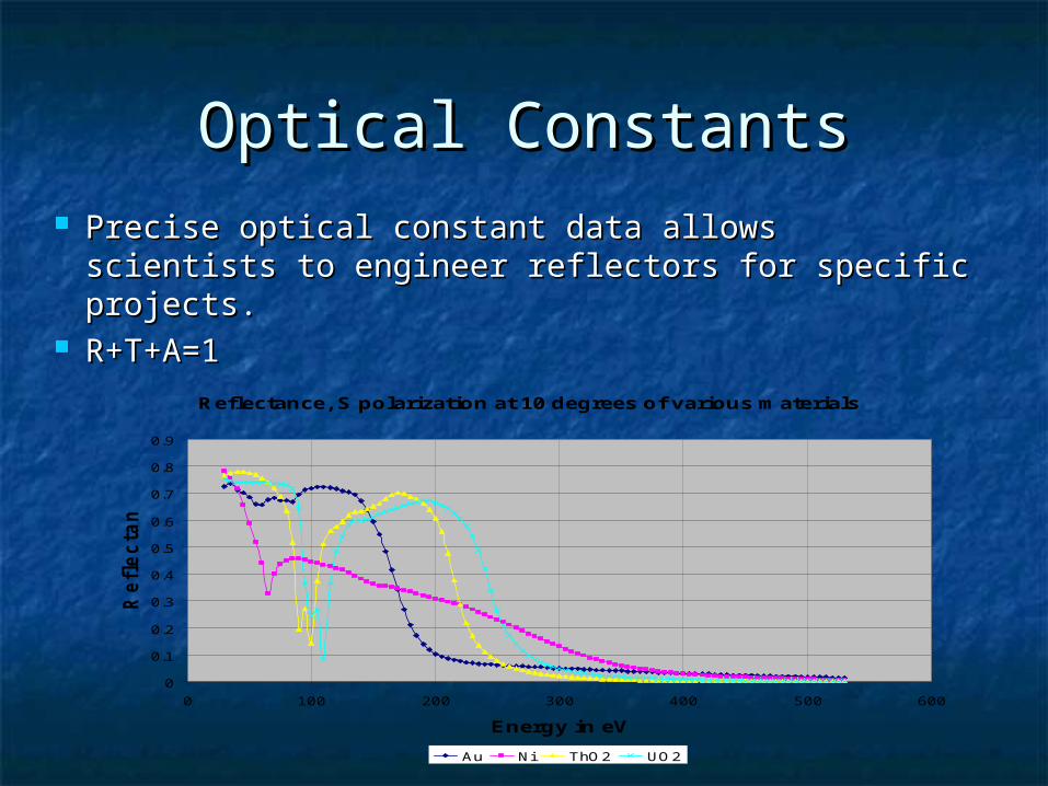
Optical ConstantsOptical Constants Precise optical constant data allows scientists to Precise optical constant data allows scientists to
engineer reflectors for specific projects. engineer reflectors for specific projects. R+T+A=1R+T+A=1
Reflectance, S polarization at 10 degrees of various materials
0
0.1
0.2
0.3
0.4
0.5
0.6
0.7
0.8
0.9
0 100 200 300 400 500 600
Energy in eV
Re
fle
cta
nc
e
Au Ni ThO2 UO2

Optical Constant Optical Constant Determination from Determination from
Transmission MeasurementsTransmission Measurements•CXRO has compiled optical constants which were usually measured from transmission measurements and Kramers-Kronig analysis
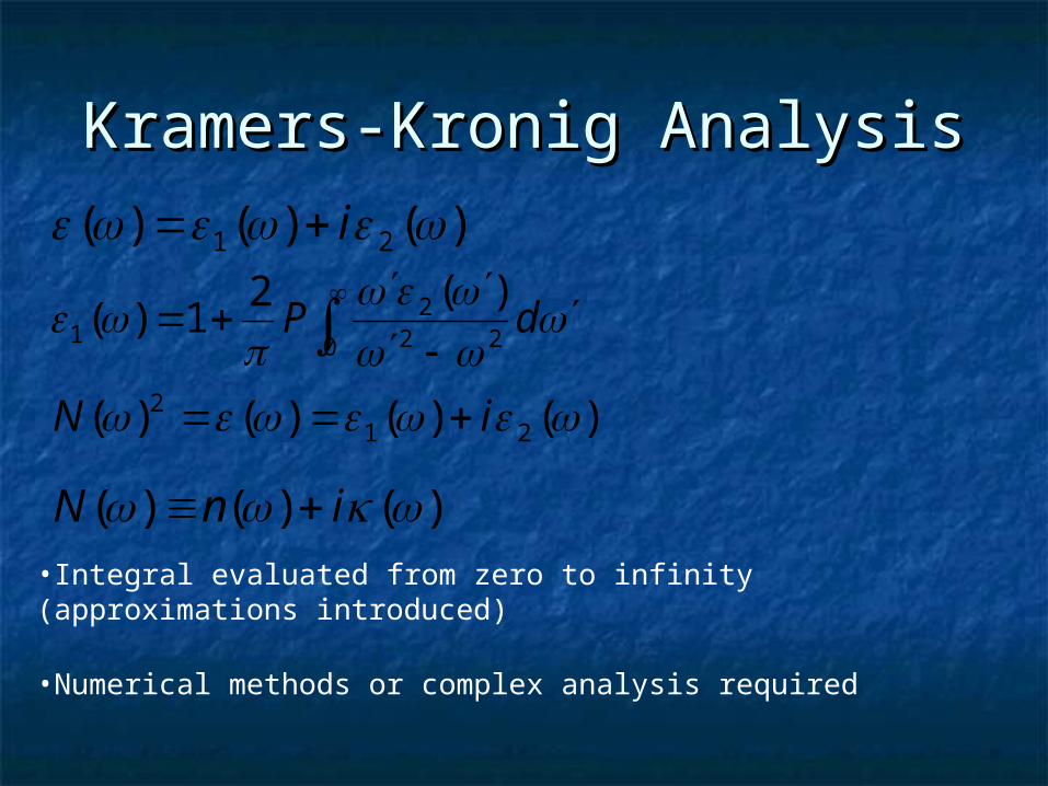
Kramers-Kronig AnalysisKramers-Kronig Analysis)()()( 21 i
0 222
1
)(21)(
dP
)()()()( 212 iN
)()()( inN •Integral evaluated from zero to infinity (approximations introduced)
•Numerical methods or complex analysis required
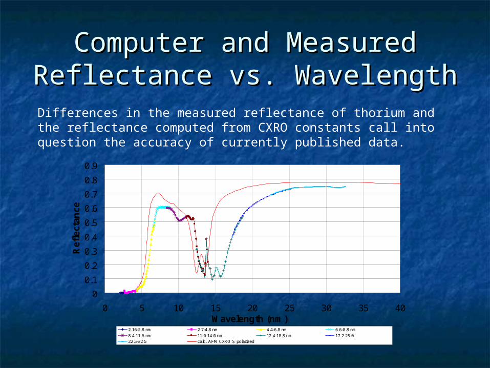
Computer and Measured Computer and Measured Reflectance vs. WavelengthReflectance vs. Wavelength
0
0.1
0.2
0.3
0.4
0.5
0.6
0.7
0.8
0.9
0 5 10 15 20 25 30 35 40Wavelength (nm)
Ref
lect
ance
2.16-2.8 nm 2.7-4.8 nm 4.4-6.8 nm 6.6-8.8 nm8.4-11.6 nm 11.0-14.0 nm 12.4-18.8 nm 17.2-25.022.5-32.5 calc. AFM CXRO S polarized
Differences in the measured reflectance of thorium and the reflectance computed from CXRO constants call into question the accuracy of currently published data.

Simultaneous Reflection and Simultaneous Reflection and Transmission MeasurementsTransmission Measurements
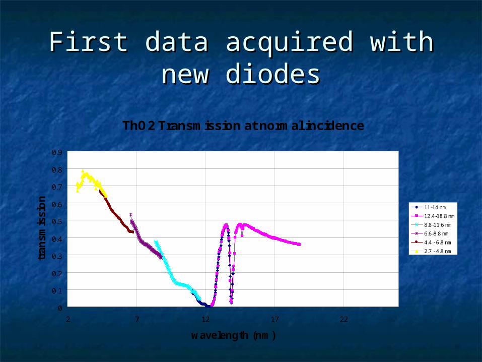
First data acquired with new First data acquired with new diodesdiodes
ThO2 Transmission at normal incidence
0
0.1
0.2
0.3
0.4
0.5
0.6
0.7
0.8
0.9
2 7 12 17 22
wavelength (nm)
tran
smis
sio
n
11-14 nm
12.4-18.8 nm
8.8-11.6 nm
6.6-8.8 nm
4.4 - 6.8 nm
2.7 - 4.8 nm
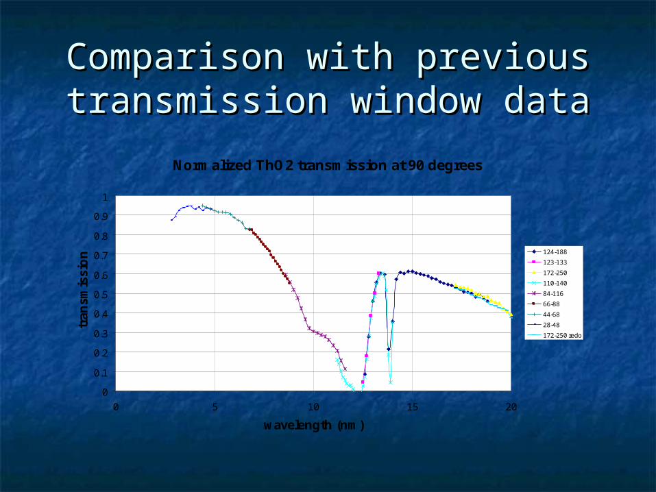
Comparison with previous Comparison with previous transmission window datatransmission window data
Normalized ThO2 transmission at 90 degrees
0
0.1
0.2
0.3
0.4
0.5
0.6
0.7
0.8
0.9
1
0 5 10 15 20
wavelength (nm)
tran
smis
sio
n 124-188
123-133
172-250
110-140
84-116
66-88
44-68
28-48
172-250 redo
ConclusionsConclusions
We believe our methods will provide We believe our methods will provide the most accurate optical constant the most accurate optical constant measurements in the EUV.measurements in the EUV.
Remainder of data taken in March Remainder of data taken in March 2005 must be analyzed and fit.2005 must be analyzed and fit.
Acknowledgments Acknowledgments
BYU XUV Research Group colleaguesBYU XUV Research Group colleagues Dr. David D. Allred Dr. David D. Allred Dr. R. Steven TurleyDr. R. Steven Turley BYU Physics Department Research BYU Physics Department Research
FundingFunding