detonation/pre-ignition and the outboard motormembers.iinet.net.au/~pauldawson/deton-pwd-94.pdf ·...
TRANSCRIPT

Page 1
DETONATION/PRE-IGNITION AND THE OUTBOARD MOTOR One of the most common causes of major internal engine damage results from the abnormal combustion conditions that have plagued the internal combustion engine since it's beginning, namely - Detonation and Pre-ignition, or Surface ignition. In racing and high performance engines detonation is responsible for more problems than any other cause. [12] These combustion related problems have been the major limiting factor to internal combustion engine power development since the beginning, and will be present at some stage of life in all engines, in varying degrees of severity, although usually only very briefly. Definitions - Detonation Spontaneous, and extremely rapid, combustion of a portion of the fuel
air mix in the combustion chamber. Pre-Ignition Ignition of the fuel/air mix in the combustion chamber by a "hot spot"
or similar source of ignition, before the spark. Surface Ignition Ignition of the fuel/air mix inside the combustion chamber by a "hot
spot" or similar on the metal surface of the chamber or piston crown, either before or after the spark.
What happens, normal combustion - 1. Piston rises in the cylinder compressing and heating the fuel/air mix. Turbulence from the
scavenging process, helped by combustion chamber shape, is vaporising the tiny droplets of liquid fuel mixed with the air. Turbulence is essential (and thankfully to some extent automatic) as the linear speed of a flame front in a stationary fuel/air mix is only around 0.5 m/sec. We need at least 15 m/sec to get across the combustion chamber in the time available. [1]
2. At the ignition timing point, an electrical spark occurs across the electrodes of the spark plug.
Actually, at first there is only an electrical potential across the gap which acts upon any charged particles in the gap (there is always some, negative electrons or positive ions) causing them to accelerate and collide with more molecules causing more and more ions.
This begins a chain reaction, called ionisation, within the fuel/air molecules in the spark plug
gap raising their temperature until a small fire occurs and is big enough to be caught by the turbulent flow in the chamber. This is the ignition delay period of about 0.5 ms (15 degrees at 5000 rpm), and is fairly constant. Refer to figure 1, points A to B, about 10 degrees. [1]
3. As soon as the ignition delay period finishes, the flame starts to spread across the combustion
chamber at a speed determined by temperature, fuel/air mix and turbulence. Typical combustion (flame) speed begins at around 10 m/sec (40 kph) rising to over 40 m/sec (140 kph) before

Page 2
combustion is complete. [2] The speed of combustion is primarily determined by turbulence in internal combustion engines
and as turbulence automatically increases with rpm, occupies a similar number of degrees of rotation across a wide rpm range. Refer to figure 1, points B to C, about 50 degrees. [1]
4. Maximum pressure occurs in the combustion chamber at approx. 20 ATDC, just before
complete combustion and the expanding gasses drive piston down with great force. Refer to figure 1, max pressure approx. 48 Bar (700 psi) at 20 degrees ATDC. The temperatures in the combustion chamber will be about 275ΕC at ignition, up to 1800ΕC at maximum pressure, dropping to about 700ΕC when exhaust port/valve opens. [5]

Page 3
What happens with detonation. 1. Compression, ignition and ignition delay periods all occur, as for normal combustion 2. The flame starts to travel across the chamber, with the expanding gasses behind the flame front
raising pressure in the whole chamber, compressing the as yet unburnt fuel/air mix in the far reaches of the chamber. If pressure rises fast enough, the temperature of some of the unburnt portions in the chamber will rise to auto-ignition point and spontaneous combustion occurs. The auto ignition point for normal automotive petrol is approx. 390Ε C. [3]
The portions of the fuel/air mix most likely to detonate are those furthest from the point of
ignition (spark plug), often called the end gasses because they are usually the last to burn, and are therefore at the "end" of the flame travel.
3. Because a portion of the fuel/air mix has "exploded", rather than burning at the rate of flame
travel, maximum pressure is reached too early, often before TDC. In a multi-cylinder engine detonation in one cylinder is often not noticeable because the other cylinders continue to operate normally.
Figure 2 shows the effect of changing from 12 to 1 compression ratio at part throttle and no
detonation, to w.o.t. and violent detonation (called pre-ignition in this instance), before the
variable compression ratio mechanism can react and lower the ratio to 9 to 1. [4] This graph is from an experimental engine with variable compression ratio to improve fuel efficiency at part throttle.

Page 4
5. Detonation causes very sudden pressure rises, and in the region where the "explosion" actually takes place the shock is violent enough to destroy the thermal boundary layer that is normally present on all the metal surfaces in the chamber. Removal of the thermal boundary layer increases of the heat transfer into the metal and raises it's local temperature, making more detonation and/or surface ignition likely. [1]
Pre-Ignition and Surface Ignition 1. These are the same as for detonation, except - 2. Ignition of the fuel/air mix is caused by something other than the spark, often very early in the
stroke, leading to very sudden rise in pressure and temperature in the chamber, which leads to detonation of a larger portion of the fuel/air mix, which in turn causes a large increase in local temperatures, and the process rapidly escalates.
Surface ignition, as the name implies, is ignition of the fuel/air mix by a high temperature spot on the surface of the chamber (spark plug, cylinder head, head gasket or piston crown). The ignition can take place before the spark (pre-ignition) or after (post-ignition), but with similar results - pressure rise is very rapid and too early causing raised temperatures and detonation of the fuel/air mix. Detonation, by itself, is generally confined to small portion of the combustion chamber. Mild detonation is called "knocking" because of the noise that can be heard when it happens at low power settings. Knocking is generally not heard at high speed and power settings because of the noise developed in air intake or exhaust system is louder and masks it. Mild detonation is present in all engines at some time. Often it can be heard when accelerating a car from low speed. In these cases the detonation is only small, and transient, as it stops once the speed stabilises or the throttle is reduced. For constant high power output engines, like marine and aircraft engines, piston crowns and combustion chamber walls are designed relatively thick and can usually withstand the hammer blows of mild detonation without physical damage. The rise in temperature leading to surface ignition, then severe detonation, is what does the damage. The damage then shows up as metal having melted away in the hottest areas, or seizure of the piston where it has expanded the most. Engines designed for only infrequent, and brief, high power settings, such as many cars and motorcycles, do not have these thick metal sections and can not always withstand even mild detonation, which then shows up as cracked and broken piston crowns or ring land areas. A result of the hammer blows from the very sudden pressure rise. Detonation is an old problem Problems with "Knock" have been around since the beginning of the internal combustion engine. It is true to say that the limits imposed by detonation have been one of the major obstacles preventing engine design from progressing at a faster rate. In some cases engine designs could not progress until fuel with a better detonation resistance was available, and in others a design that was better at resisting detonation,

Page 5
but perhaps not in other areas, was chosen because of this advantage. For more information on the history of detonation, refer to Appendix 1. Avoiding detonation The engine designer is responsible for avoiding many of the possible detonation causes such as - - Long flame travel, brought about by a torturous combustion chamber design. Figure 8 shows the
octane requirements of several different combustion chamber shapes in otherwise similar (4-stroke) engines.
- Basic compression ratio, which must match the available fuels to the engine's requirements, - Scavenging efficiency which determines the cylinder filling ability, and is very much controlled
by the exhaust system in two stroke engines. - Other areas like the air density range likely where the engine is to be operated, (high altitude,
high ambient temperatures etc.) which determines the amount of oxygen available for combustion.
These are all decisions made during design and development and not normally within the influence of the installation and repair technician. However any technician wishing to alter the design, for example to increase power for racing, must be aware of taking on an additional set of responsibilities, those of designer, which must be considered in addition to the more common service related issues mentioned below. The service technician must be aware of these common service related detonation "triggers", especially important when diagnosing an engine failure. 1. Low octane fuel - Use of the wrong grade of fuel - Use of old fuel where oxidation has taken place (degrading
some of the compounds that are responsible for maintaining

Page 6
octane level) or where evaporation has removed much of the "light ends" that are responsible for easy starting and good fuel/air mixing for a homogenous mixture.
2. Over advanced timing - Ignition timing set using wrong specifications. - Ignition timing set using wrong equipment (timing light or
fixture) - Ignition timing set using wrong method (rpm too low) - Ignition timing set using wrong reference marks (timing
pointer position incorrectly adjusted) 3. Overloading - WOT throttle rpm too low, from propeller pitch too high, a
large increase in carried load, marine growth on hull, trim altered to increase drag. WOT allows minimum charge dilution (by exhaust gasses) and maximum turbulence, so cylinder contents will have a fast burn rate intended for high rpm. If rpm is too low, peak pressures will be exerted too early, in a similar manner to over advanced timing.
4. High surface temperatures - If piston crown or combustion chamber surfaces are hotter
than intended, the incoming charge is heated early in the compression stroke and detonation temperatures can be reached before combustion is complete. High surface temperatures can be caused by a cooling system that is hotter than normal (thermostat or pressure relief valve problem).
- Insulating deposits on piston skirts also raise surface
temperatures through retarding heat transfer to the cooling system.
- Deposits on combustion chamber walls can become hot
enough to cause surface ignition (pre-ignition), through being "layered" with the inner layers insulated from the cooling system by the outer layers.
Page 7
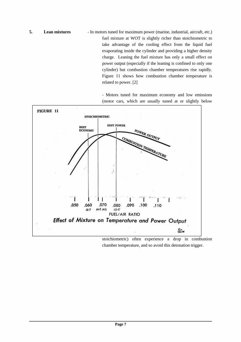
5. Lean mixtures - In motors tuned for maximum power (marine, industrial, aircraft, etc.) fuel mixture at WOT is slightly richer than stoichiometric to take advantage of the cooling effect from the liquid fuel evaporating inside the cylinder and providing a higher density charge. Leaning the fuel mixture has only a small effect on power output (especially if the leaning is confined to only one cylinder) but combustion chamber temperatures rise rapidly. Figure 11 shows how combustion chamber temperature is related to power. [2]
- Motors tuned for maximum economy and low emissions
(motor cars, which are usually tuned at or slightly below
stoichiometric) often experience a drop in combustion chamber temperature, and so avoid this detonation trigger.

Page 8
6. Compression ratio - The compression ratio of production outboard motors is fixed at manufacture to match the specified fuel requirements. Changes to compression ratio, as a result of servicing the engine, can effect the engines octanes requirement. Figure 15 show the effects of cylinder boring and head shaving on compression ratio on a common large outboard motor. If this motor is both rebored .030" oversize and the cylinder is shaved .030", the compression ratio is raised from 6.0 to 6.4. This could result in an increase of octane requirement of 1.5 to 2.5 RON numbers. [7]

Page 9
What variables influence detonation? How much do the circumstances mentioned above influence detonation? Figure 12 shows the effect of the common variables on the octane number requirement of modern engines. Increases in compression ratio, fuel/air ratio (leaner), spark advance, surface temperature and ambient air temperature all increase the octane requirement of a given engine, or the likelihood of detonation. Only higher altitudes and higher humidity reduce the octane requirement of an engine (through reduced oxygen content), conditions that are very rare for marine engines. [7] Engine manufactures design their engines with a margin of safety with regard to octane requirement. This is because some of the variables mentioned above are likely to present due to weather conditions,
and because production tolerances mean higher compression ratios, or higher surface temperatures for some engines. However, if these variables are combined with old or wrong fuel, the wrong size prop or an incorrectly timed engine, the recipe for damage is complete. Diagnosis If detonation is severe enough the piston crown will be cracked or broken by the hammer blows. Figure 13 shows how the physical piston can damage differ between detonation only or surface ignition (pre-ignition). [12] As mentioned previously, marine engines have thick section piston crowns that generally don't suffer from the hammer blows of detonation, but from the temperature increase which results in surface ignition.

Page 10
Depending on the severity of the detonation or surface ignition, and the design of the engine, one of several scenarios is likely, in usually the following order - 1. Relatively mild damage will show up as either - Seizure on the exhaust side of the piston, concentrated near the rings (because the thicker
sections result in greater expansion here), with possibly some seize marks directly opposite where piston ovality has broken through the oil film, if the temperature rise was concentrated
around the exhaust port, or - Seizure along side the wrist pin holes, if the temperature rise is more evenly spread through the
piston, resulting in four seizure areas (again because the metal is thickest and expands more in these areas).
The beginnings of detonation also often shows up as a "sand blasted" or "peppered" appearance
on the piston crown, usually near the top ring land or chamber walls which is a result of the small explosions in the area.
Figure 14 shows the type of seizure visible with relatively mild detonation damage. 2. Continued temperature rise will start to see metal melting at the hottest areas, usually the piston
crown or ring land areas near the exhaust port on loop charged models. In the case of crossflow models the sharp edges on the transfer side of the piston deflector are usually the first to melt and will exhibit a rounded and "sand blasted" appearance.

Page 11
Melted metal often ends up on the spark plug electrodes, causing a misfire and reducing further damage, and also giving a visible signal to the technician that detonation has occurred.
3. Severe damage will show up as a hole melted through the piston crown, or through the ring land
area, generally continuing until the cylinder no longer has compression. Figure 13, under the heading Pre-Ignition, shows this type of damage.
4. If an engine can continue to run with severe detonation or surface ignition long enough piston
seizure will become bad enough for the piston to break up. Heat will weaken the piston until the wrist pin is pulled out of it's bosses or the piston skirt breaks into several pieces, either of which then causes compression to be lost.
What comes first ? Which of the above is likely to occur first, or to be the cause of the engine stopping, varies greatly from engine to engine due to factors like - Piston to bore clearance and whether piston is round or cammed. Piston design and section thickness. Cooling system design and normal temperature variation across the cylinder. Combustion chamber shape and position in the bore.

Page 12
Number of cylinders (multi-cylinder engines can easily "carry" one detonating cylinder with little overall power loss).
Just where detonation started in the combustion chamber. For example, if the end gasses near the
exhaust port were the first to detonate, then the heat build up would be worst on this side of the piston, however if the centrally located spark plug has caused surface ignition then the heat build up is likely to be more evenly spread across the piston crown.
The power output of the motor when detonation occurs. A motor running at reduced power is
more likely to be stopped by a relatively mild seizure, where as a motor operating at maximum power will usually continue running until more severe damage occurs.
Page 13
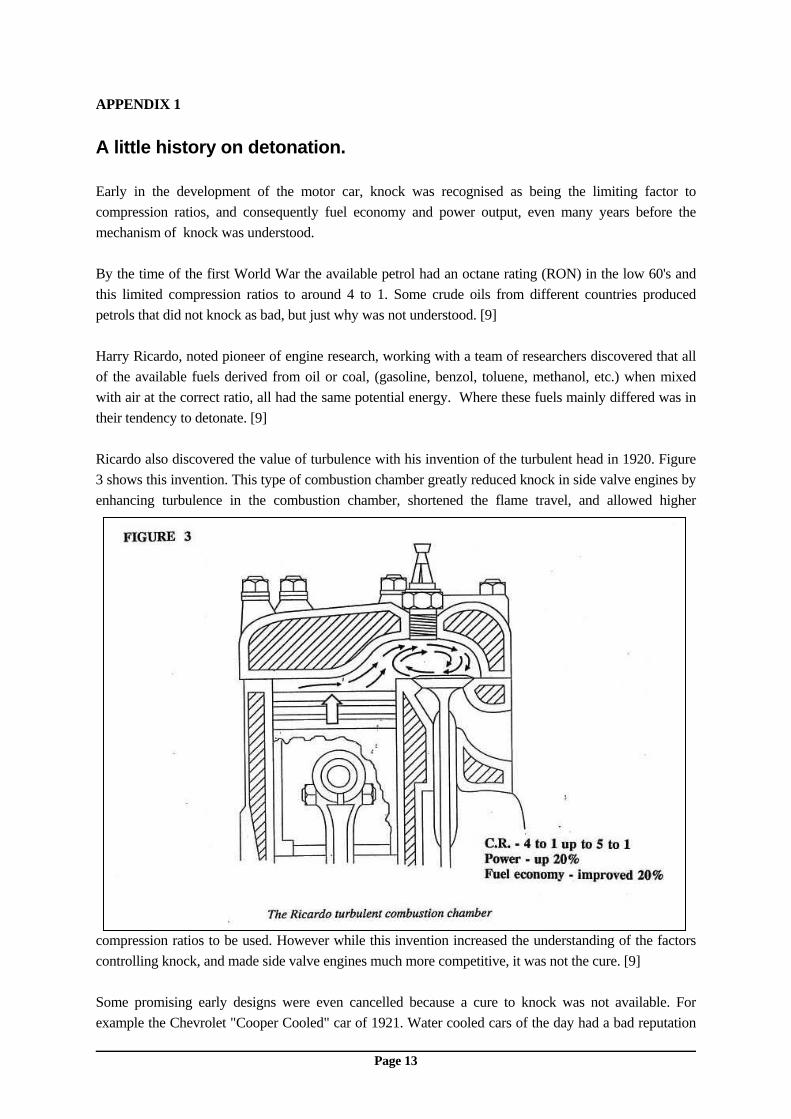
APPENDIX 1 A little history on detonation. Early in the development of the motor car, knock was recognised as being the limiting factor to compression ratios, and consequently fuel economy and power output, even many years before the mechanism of knock was understood. By the time of the first World War the available petrol had an octane rating (RON) in the low 60's and this limited compression ratios to around 4 to 1. Some crude oils from different countries produced petrols that did not knock as bad, but just why was not understood. [9] Harry Ricardo, noted pioneer of engine research, working with a team of researchers discovered that all of the available fuels derived from oil or coal, (gasoline, benzol, toluene, methanol, etc.) when mixed with air at the correct ratio, all had the same potential energy. Where these fuels mainly differed was in their tendency to detonate. [9] Ricardo also discovered the value of turbulence with his invention of the turbulent head in 1920. Figure 3 shows this invention. This type of combustion chamber greatly reduced knock in side valve engines by enhancing turbulence in the combustion chamber, shortened the flame travel, and allowed higher
compression ratios to be used. However while this invention increased the understanding of the factors controlling knock, and made side valve engines much more competitive, it was not the cure. [9] Some promising early designs were even cancelled because a cure to knock was not available. For example the Chevrolet "Cooper Cooled" car of 1921. Water cooled cars of the day had a bad reputation

Page 14
for boiling and or freezing, and GM engineers considered an air cooled car would be much better. They designed a four cylinder air cooled car utilising individual iron cylinders with shrunk on copper cooling fins and a ducted, fan forced air cooling system. The cooling system worked very well with no overheating or freezing problems, and virtually no maintenance. The only trouble was the relatively hot combustion chamber walls caused loud and annoying knock, for which a solution could not be found at the time and the project was cancelled before production began. [6] The key to raising the knock resistance of petrol was found by chemists Midgely and Boyd, in 1922, in the form of adding Tetraethyl lead (TEL). The addition of 0.5 grams of lead per litre of TEL raises the RON about 5 numbers. [1] The octane of commercially available fuel jumped from the low 60's into the mid 70's allowing compression ratios of around 6 to 1, with similar increases in fuel efficiency and power output.
Higher compression ratios are essential for getting as much as possible of the energy in the fuel converted into heat, and consequently power output. Figure 4 demonstrates the relationship between compression and octane requirement for typical 4 stroke engines. [10] An example of how fuel and knock resistance governed engine development was the Rolls Royce R series of aircraft engines. Developed from an existing V12 engine, the Rolls Royce Buzzard, it was intended for winning the international Schneider Cup sea-plane races starting with the 1929 event. Over the next two years power output was trebled by furious development, much of which was only made possible by the special fuel brews created by F. W. Banks of the Associated Ethyl company. [8] Figure 5 shows the power development details. This same engine was later used to set both land and water world
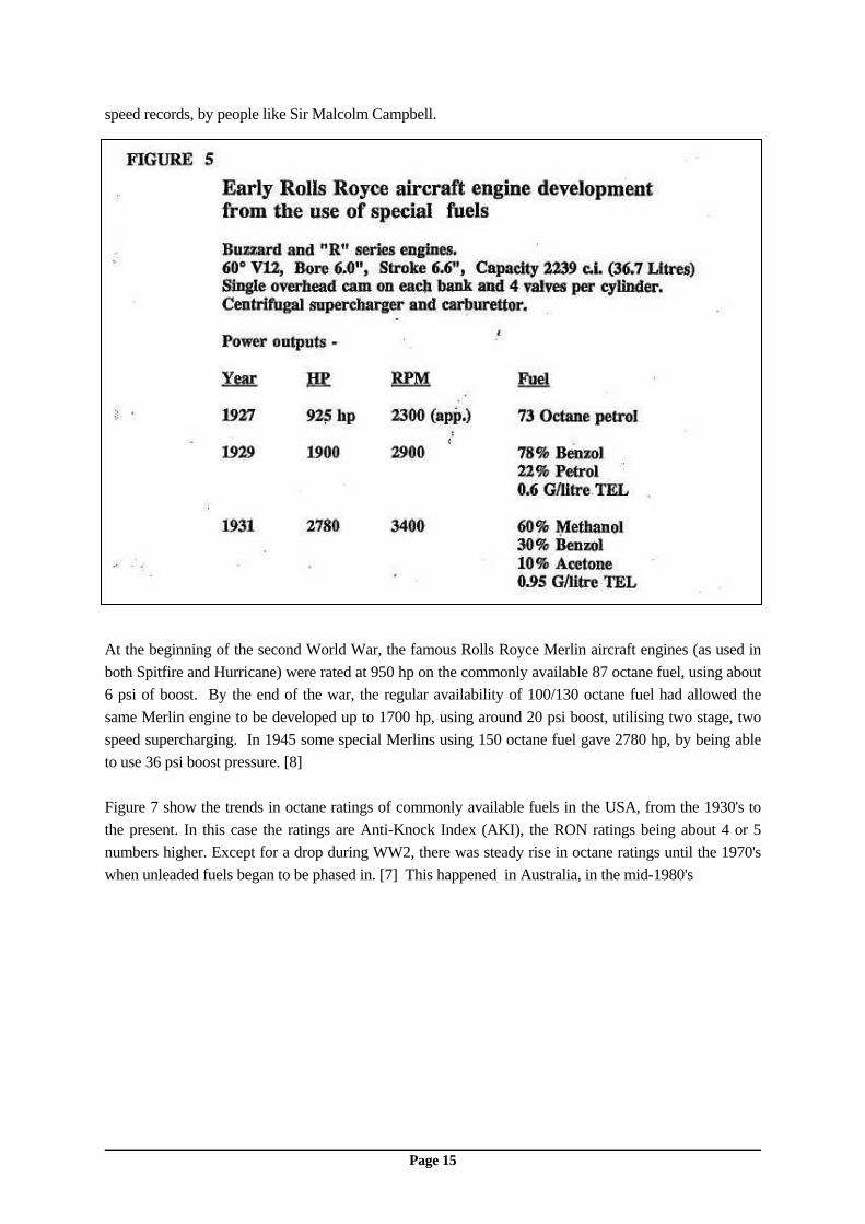
Page 15
speed records, by people like Sir Malcolm Campbell.
At the beginning of the second World War, the famous Rolls Royce Merlin aircraft engines (as used in both Spitfire and Hurricane) were rated at 950 hp on the commonly available 87 octane fuel, using about 6 psi of boost. By the end of the war, the regular availability of 100/130 octane fuel had allowed the same Merlin engine to be developed up to 1700 hp, using around 20 psi boost, utilising two stage, two speed supercharging. In 1945 some special Merlins using 150 octane fuel gave 2780 hp, by being able to use 36 psi boost pressure. [8] Figure 7 show the trends in octane ratings of commonly available fuels in the USA, from the 1930's to the present. In this case the ratings are Anti-Knock Index (AKI), the RON ratings being about 4 or 5 numbers higher. Except for a drop during WW2, there was steady rise in octane ratings until the 1970's when unleaded fuels began to be phased in. [7] This happened in Australia, in the mid-1980's

Page 16
The steady rise in available octane ratings has meant that resistance to detonation was constantly improving and compression ratios were generally increased to make use of the extra power and fuel efficiency possible. Now many older motors cannot use the latest fuels because the octane rating is too
low. Engine design is now changing to allow designs that are less sensitive to fuel octane ratings. This is demonstrated in the smaller, simpler, combustion chamber designs that loop charged engines allow, even though these engines still don't match the older crossflow designs when it comes to part throttle scavenging and ease of construction. Figure 8 shows the effects of combustion chamber shape on octane requirement, in this instance with four stroke engines. The reduced requirement for small, concentrated chambers is clearly evident. [11] Figure 9 shows the octane requirements and Figure 10 the compression ratios of large OMC outboards, over the last 20 years. The close link between compression ratio and octane requirement can be seen.

Page 17
Page 18
References [1] "Introduction To Internal Combustion Engines" Richard Stone, Macmillan Press, Hampshire UK, 1992 [2] "Aircraft Performance Engineering" United States Air Force, December 1954. [3] Technical Data Sheet TDS 7 - 1990 Australian Institute of Petroleum Ltd. [4] "Designing The Modern Engine" Article in SAE-A magazine, by R. Chadwick, Mitsubishi Motors Australia. [5] "Heat Engines and Applied Heat" F. Metcalf, Cassell, London, 1982. [6] from a book by Alfred P. Sloan on his 30 or so years as President of GM. [7] "Motor Gasolines" Lubricant Service group, Chevron Research and Technology Corp., USA, 1990. [8] "The World Encyclopaedia of Aero Engines" Bill Gunston, Patrick Stephens books, UK, circa 1986. [9] "The Ricardo Story" (Autobiography of Sir Harry Ricardo) H. Ricardo, SAE publications, USA, 1992 [10] "BP Petroleum Fuels Primer" BP Australia Ltd., Fuel and Laboratory Services, 1990 [11] From 1940/1950's research by Ricardo, as related in "The History of the Internal Combustion Engine", ASME Published by SAE, 1989 [12] "High Performance and Racing Heat Range Chart and Tuning Guide" Champion Spark Plug Company. PWD Jan 1994