detonators, igniters, primers, and other … · detonators, igniters, primers, and other initiating...
TRANSCRIPT

DETONATORS, IGNITERS, PRIMERS,AND OTHER INITIATING DEVICESUSED FOR NONMILITARY AND MILITARYPURPOSES
PrefaceIn the pages which follow, this subjectis treated separately for items used for nonmilitaryand military purposes. As the subjectis very extensive, it is separated intoseveral sections. The references and additionalreferences given at the end of thiscompilation apply to all sectionsThe items used for military purposesinclude those used for small arms ammunition,artillery ammunition, rocket ammunition,aircraft bombs, land & sea mines, grenades,demolition devices and pyrotechnicdevices. As some items (such as detonators,primers, etc) can be used in several kindsof ammunition our write-up might containsome repetitions
Section 1DETONATORS, IGNITERS AND PRIMERSUSED FOR NONMILITARY PURPOSESPart ANonmiIitary Ignitersigniters, which include devices calledsqu~bs, lighters and firing devices, etc areused for initiating expl or pyrotechnic compnswhose nature is such that it is desirable touse flame or flash for their initiation and nota shock as produced by primers or detonators., Explosives of this kind are known as deflagtatingor iow explosives. BkPdr and smoke-“less propellants are examples. The simplestdevice for ignition is B ickford or Miner’ssafety fuse, described in Ref 44, p B1 12-L.In Ref JO, pp 915-101 is described the safetyfuse and the following devices for ignitingit: ordinary matches, lead spitter fuse lighter,ignitacord and quarry cord. The lead spitter/use lighter consists of a thin lead tubingfilled with BkPdr and wound on. a feel. Aftercutting with a knife a piece of tubing,the powder is ignited with a match and lighted‘ end approached to the open end of safety fuse.The continuous spit of flame of intense heatwill ignite the fuse, making the slitting of fuse unnecessary. The pull wire fuse lighterconsists of a paper tube closed at one endand contg an igniting device consisting ofa striker compd on a wire which protrudesthtu the closed end. In use, the safety fuse

is inserted into the open end of the lighteruntiI it slightly touches the wire. It isheld in place by means of metal gripperteeth on the inside of the tube. Then theprotruding wire is pulled and this ignites thestriker compd and the fuse. The hot wire/use lighter consists of a wire covered withan ignition composition that but ns sIowlywith intense heat, and at a fairly steadyrate. The device is lighted by a match andthe flame is held against the freshly cut endof safety fuse. lgnitacord is a device cordlikein appearance which burns progressivelyaIong its length. The flame is short andhot and offers a means of lighting a seriesof safety fuses in the desired rotation. Twotypes, A & B, are manufd by the DuPont Co.The use of ““ ignitacord ““ is described in Ref50, PP 130-33. Quarrycord is another COrdtypeburning igniter designed mainly for firinga large number of quarry charges in secondaryblasting. The use of ““ quarrycord ““is described in Ref 50, pp 133-34. ““Secondaryary blasting ““~fo IIows quarry blasting operationsin order to break up large rock chunksand boulders into pieces sufficiently smallto feed into crushers (Ref 50, p 347)The DuPont Co makes aIso eIectric ignitingdevices, called electric squibs (Ref50, pp 94-5). Three types of US electricsquibs patented by Burrows et al, are describedin Ref 44, pp B212 to B214No description of British devices correspondingto US electric squibs is foundin Brit books on explosives in our possession,such as Refs 36, 38 & 51. In Ref 38; p 59is, however, a description of an electricdevice which probably serves the same purpose.It is an electric powder fuse, whichconsists of a thick paper tube contg a smalIchge of Blasting Powder (Brit for Black Powderor Gunpowder), with an ordinary lowtensionfusehead fixed at one end. On passingelectric current thru the fus”ehead it flashesand sets off the BkPdr in the tube, which can then ignite the main chge of BkPdr in the shothole. This device was created so that electricalshot-firing methods could be used forinitiating deflagrating expls like BkPdrIn the DuPont’s Hdb (Ref 50, p 187), thedevice consisting of a paper cartridge ofBkPdr in which a safety fuse is inserted iscalled black powder primer with safety fuse,and the device combining a BkPdr cartridgewith an electric squib or cap is called blackpowder primer with electric squib or cap.

As these devices are used for igniting andnot for detonating low expls like BkPdr,their correct names should be ““ igniters ““
Section 1, Part BNonmilitary Primers
Primers used for nonmilitary (commercialor industrial) purposes are devices whichinitiate high explosive charges (such asDynamites) by shock produced on detonationof primary charges and not by a flash orflame as in the case of ignitersOne of the simplest primers is a combinationof ““nonelectric cap ““(Brit ‘“ pIain detonator~ with safety fuse (Bickford fuse)and a cartridge of Dynamite, as shown inFig 1. This combination is called in US
Fig 1 DYNAMITE PRIMER““Dynamite primer ““ and in Gt Britain ““primercartridge’1 For its preparation, one cutsacross a safety fuse with a clean sharp knife(or fuse-cutter) a required length and insertsfreshly cut end into open end of blasting cap.Using a proper crimping ted, the cap iscrimped near its open end to hold the fusesecurely in position. This combination isknown in Gt Brit as “tapped fuse “j Thenext step is to open the Dynamite cartridgeat one end and to make a hole with an Al,Cu, brass or wooden pricker, then to insertthe cap into the hole and to tie the cartridgepaper tightly around the fuse above the cap(Ref 38; p 71). Other methods of prepn of““Dynamite. cartridge ““are given in Ref 50,pp 191-94Electric blasting caps can be used in lieuof nonelectric ones for prepn of primer cartridges.For this, the hole is made in a cartridgeof Dynamite as described above and,after inserting the cap, the electric wires ofthe cap are tied around the cartridge to prevent

the cap being withdrawn accidentallyduring loading or handling (See Fig 2) (Ref 3,p 72 and Ref .50, p193)
Fig 2 DYNAMITE ELECTRIC PRIMERDynamite primers with LEDC (low energydetonating cord) delay assemblies made by‘the DuPont Co are described in Ref 50, pp106-09 & 192-93. They are essentially““nonelectric MS(microsecond) delay caps”~The LEDC produces very little noise ondetonation and for this reason can be usedin highly populated areas. It is usually recommendedfor operations where bottom-hoIeinitiation is desired and electric blasting capscannot be used for fear of premature detonations from stray current or other extraneouselectricity. These primers are assembled thesame way as the ““capped fuse ““(See Fig I)““EL-primers ““are Iisted in Ref 50, p 194as ““ speciaI non-nitroglycerin primers ““designedspecifically for priming blasting agentsin smaIl diameter boreholes. Their physicalappearance is much the same as smalldiameter Dynamite and the recommended methodsof primer assembIy are exactly thesame as for Dynamite. Their compn is notgiven in Ref 50‘“Sheathed primers “o consist of Dynamitecartridge primers inserted in cylindricalpaper or cardboard containers of slightlyIarger ID than OD of cartridges. The capsmay be either nonelectric combined with safetyfuse, or electric. The sheath prevents thecap from coming out of the cartridge, adds
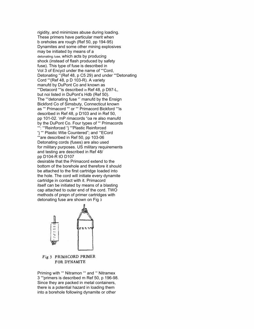
rigidity, and minimizes abuse during loading.These primers have particular merit whenb oreholes are rough (Ref 50, pp 194-95)Dynamites and some other mining explosivesmay be initiated by means of adetonating /use, which acts by producingshock (instead of flash produced by safetyfuse). This type of fuse is described inVol 3 of Encycl under the name of ““Cord,Detonating “’(Ref 48, p C5 29) and under ““DetonatingCord ““(Ref 48, p D 103-R). A varietymanufd by DuPont Co and known as““Detacord ““is described in Ref 48, p D97-L,but noi listed in DuPont’s Hdb (Ref 50).The ““detonating fuse “’ manufd by the EnsignBickford Co of Simsbuty, Connecticut knownas ““ Primacord ““ or ““ Primacord Bickford ““isdescribed in Ref 48, p D103 and in Ref 50,pp 101-02. ‘mP rimacords “oa re also manufdby the DuPont Co. Four types of ““ Primacords““: ““Reinforced “j ““Plastic Reinforced“j ““ Plastic Wtie Countered”; and ‘“ECord““are described in Ref 50, pp 103-06Detonating cords (fuses) are also usedfor military purposes. US military requirementsand testing are described in Ref 48/pp D104-R tO D107desirable that the Primacord extend to thebottom of the borehole and therefore it shouldbe attached to the first cartridge Ioaded intothe hole. The cord will initiate every dynamitecartridge in contact with it. Primacorditself can be initiated by means of a blastingcap attached to outer end of the cord. TWOmethods of prepn of primer cartridges withdetonating fuse are shown on Fig 3
Priming with ““ Nitramon ““ and ‘“ Nitramex3 ““primers is described m Ref 50, p 196-98.Since they are packed in metal containers,there is a potential hazard in loading theminto a borehole following dynamite or other
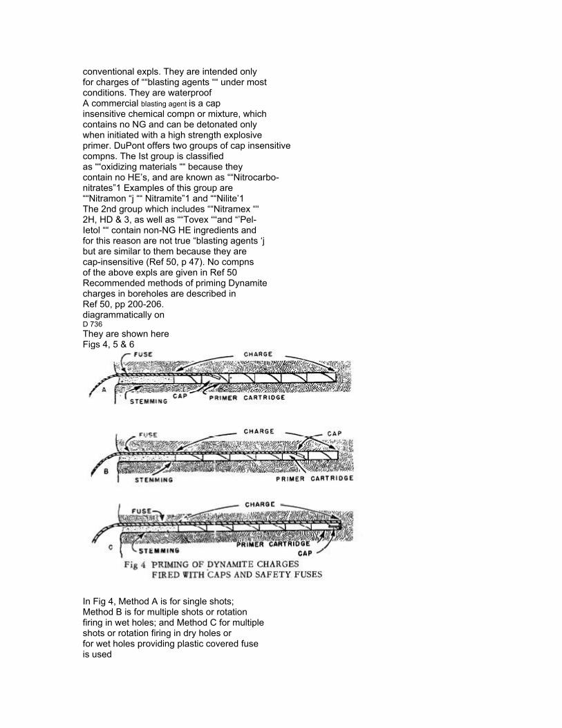
conventional expls. They are intended onlyfor charges of ““blasting agents ““ under mostconditions. They are waterproofA commercial blasting agent is a capinsensitive chemical compn or mixture, whichcontains no NG and can be detonated onlywhen initiated with a high strength explosiveprimer. DuPont offers two groups of cap insensitivecompns. The Ist group is classifiedas ““oxidizing materials ““ because theycontain no HE’s, and are known as ““Nitrocarbo-nitrates”1 Examples of this group are““Nitramon “j ““ Nitramite”1 and ““Nilite’1The 2nd group which includes ““Nitramex ““2H, HD & 3, as well as ““Tovex ““and “’Pel-Ietol ““ contain non-NG HE ingredients andfor this reason are not true “blasting agents ‘jbut are similar to them because they arecap-insensitive (Ref 50, p 47). No compnsof the above expls are given in Ref 50Recommended methods of priming Dynamitecharges in boreholes are described inRef 50, pp 200-206.diagrammatically onD 736They are shown hereFigs 4, 5 & 6
In Fig 4, Method A is for single shots;Method B is for multiple shots or rotationfiring in wet holes; and Method C for multiple shots or rotation firing in dry holes orfor wet holes providing plastic covered fuseis used

In Fig 5, Method A is for firing with in- ?stantaneous electric blasting caps; and Method B is for instantaneous firing and for all rotation firing with delay electric blasting caps
In Fig 6 is shown indirect priming methodrecommended in blasting permissibledynamiteIndirect Priming of the chge means theplacement of the cap in the 1st cartridgegoing into the borehole with the businessend pointing toward the coIIar. In contrastto this, direct priming is where the cap isplaced in the last cartridge going into thehole and pointed toward the bottom. Indirectpriming is safer than direct priming forthe reasons listed in Ref 50, p 204
Section 1, Part CNonmilitary DetonatorsDetonators, used for nonmilitary purposes

are commonly known in US as blasting capsand they are described in Ref 44, pp B185 toB201, where also numerous references aregiven. In some US Bureau of Mines publicationsthey are called ““detonators”1 Forexample, Grant & Coates (Ref 7a, p 2) statedthat ““Detonators are used to explode permissibleexplosives, dynamites, or other highexplosives. This explosion or detonationis brought about by the energy which is liberatsdas a combination of concussion and heatwhen the detonator is fired ““The blasting caps are subdivided intononelectric caps, which can be single-componentand compound caps, also called ““ two-part detonators“’(Ref 44, pp B185 to B186-R); electriccaps, which can be high tension, low tensionand match-head type (Ref 44, pp B 186-Rto B188-L); and delay electric cap (p BIWI-L )There are also a special blasting cap, suitablefor seismographic explorations and US Armyspecial blast ing caps, nonelectric and electric(Ref 44, p B 188-R). ““Western Big Inch BlastingCaps ““are briefly described in Ref 44, p B186-RIn Gt Britain devices corresponding to USblasting caps are called commercial detonators,Originally devices corresponding to US nonelectriccaps, known in Gt Britain as plaindetonators, contained a single expl chge consistingof a mixture of 80% MF & 20% K chlorate.There was a series of ten detonators and thewt of MF mixt in the No 6 detonator was lg.Later a switch was made to the (Azide-Styphnate-Aluminum) ASA/Tetryl detonator (Ref 43,p A493-R) and only No 6,& No 8 detonatorscontinued to be manufd. For example the NO 8,
manufd by the Nobel Society, contained O. 35gof LA-LSt mixture and 0..55g of Tetryl (Ref 29a,p 77). The most recent change has been thesubstitution of PETN for Tetryl, which gaveAS A/PETN detonator (Ref 43, p A493-R)(See also Ref 36, p 54 and Ref 38, p 52-3).Although each of these detonators contain twocharges: priming or upper (ASA) and secondaryor base (Tetryl or PETN), they are stillcalled in Gt Brit the ““ plain detonators’: Correspondingdevices are known in US as compoundblasting caps (See Ref 44, p 186-L and Fig),but the ASA detonators have no. ‘“reinforcingcup “, as do the US capsGerman detonators known at the time ofWWII are described in Ref 35, pp Ger 34 &Ger 35. The Briska detonator which originatedin Germany before WWII is described byStettbacher (Ref 3, p 348) and in Ref 35, pGer 23. In the Briska version of detonator
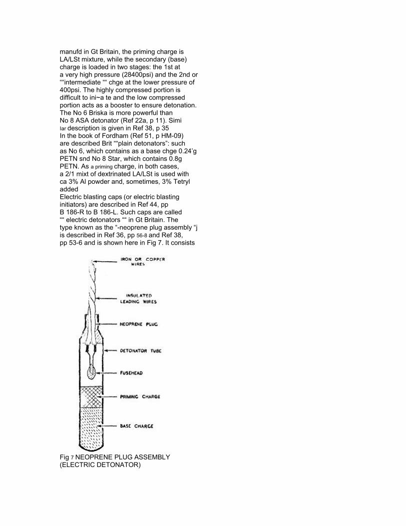
manufd in Gt Britain, the priming charge isLA/LSt mixture, whiIe the secondary (base)charge is loaded in two stages: the 1st ata very high pressure (28400psi) and the 2nd or““intermediate ““ chge at the lower pressure of400psi. The highly compressed portion isdifficult to ini~a te and the low compressedportion acts as a booster to ensure detonation.The No 6 Briska is more powerful thanNo 8 ASA detonator (Ref 22a, p 11). SimiIar description is given in Ref 38, p 35In the book of Fordham (Ref 51, p HM-09)are described Brit ““plain detonators”: suchas No 6, which contains as a base chge 0.24’gPETN snd No 8 Star, which contains 0.8gPETN. As a priming charge, in both cases,a 2/1 mixt of dextrinated LA/LSt is used withca 3% Al powder and, sometimes, 3% TetryladdedElectric blasting caps (or electric blastinginitiators) are described in Ref 44, ppB 186-R to B 186-L. Such caps are called““ electric detonators ““ in Gt Britain. Thetype known as the “-neoprene plug assembly “jis described in Ref 36, pp 56-8 and Ref 38,pp 53-6 and is shown here in Fig 7. It consists
Fig 7 NEOPRENE PLUG ASSEMBLY(ELECTRIC DETONATOR)
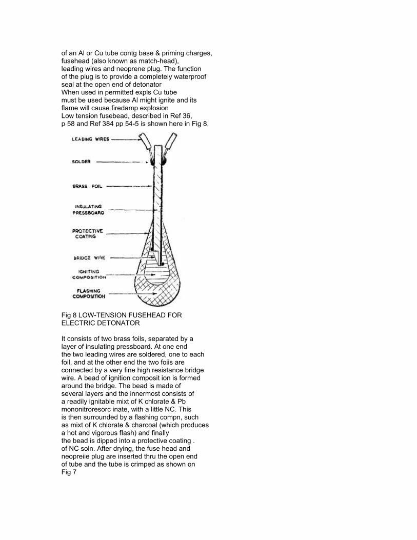
of an Al or Cu tube contg base & priming charges,fusehead (also known as match-head),leading wires and neoprene plug. The functionof the piug is to provide a completely waterproofseal at the open end of detonatorWhen used in permitted expls Cu tubemust be used because Al might ignite and itsflame will cause firedamp explosionLow tension fusebead, described in Ref 36,p 58 and Ref 384 pp 54-5 is shown here in Fig 8.
Fig 8 LOW-TENSION FUSEHEAD FORELECTRIC DETONATOR
It consists of two brass foils, separated by alayer of insulating pressboard. At one endthe two leading wires are soldered, one to eachfoil, and at the other end the two foiis areconnected by a very fine high resistance bridgewire. A bead of ignition composit ion is formedaround the bridge. The bead is made ofseveral layers and the innermost consists ofa readily ignitable mixt of K chlorate & Pbmononitroresorc inate, with a little NC. Thisis then surrounded by a flashing compn, suchas mixt of K chlorate & charcoal (which producesa hot and vigorous fIash) and finallythe bead is dipped into a protective coating .of NC soln. After drying, the fuse head andneopreiie plug are inserted thru the open endof tube and the tube is crimped as shown onFig 7

Fordham (Ref 51, pp 116-19), calls thefusehead of Fig 8 the Sandwich type fuseheadand states that it was invented by Krannichfeldin Germany. Judging by the descriptionof its method of manuf, it is similar to Germanfuseheads described in Ref 35, pp Ger53 & Ger 54Fordham describes four types of Britcommercial electric detonators (Ref 51, p 116,Fig 10. 1). The first three types are ““lowtension bridge detonators ““ and correspond toUS electric blasting initiators shown in ,Fig,p B188 of Ref 44. The 4th Brie type is”hightension,requiring at least 36 volts for itsinitiation. There is no bridge wire but electricconductivity is achieved by incorporatinggraphite in the flashing compn of fusehead!. The use of this type seems to be discontinuedin Gt Britain (Ref 51, pp 117-21)British commercial electric delay detoraatorsare described in Ref 36, pp 69-?4; Ref38, pp 56-9 and Ref 51, pp 125-30. Theearliest type introduced in Gt Britain in 1910had various lengths of Bickford fuse betweenthe fusehead and the detonator proper (Fig11.1 p 126 of Ref 5 1). An important featurewas a small hole (vent) in the detonator tube,located betw the fusehead and the fuse. Thehole initially covered with a tape (whichbroke on firing) served as a way of escapefor gases formed on burning of fuse. Thisdesign was necessary to prevent an increasein pressure which could cause too rapid burningof safety fuse. As this might cause irregularityin delay time and premature ignitionor expln of main chge, this type of detonatorwas in many cases replaced by the type ofdetonator invented by Eschbacb. In this newdetonator the delay compn (such as a mixtof K permanganate 55-7o & Sb 45-30%), whichis used in lieu of safety fuse, evolves solittle gas that there is no necessity for avent. This detonator eliminates the riskof premature expln and makes it possible toprovide fully waterproofed assemblies whichgive delay times much more regular. Such““gasless ““ delay detonators are usuallymanufd in series to fire at prearranged delaytimes with intervals of time 1 or 0.5 seesbetw the numbers. The so-called millisecondor short delay detonators are manufd with intervalsbetw each number of the series varyingbetw 25 and 50 miHiseconds (Ref 51, pp125-27)Two types of British ““electric delaydetonators ““: the “’early vented type ““ and
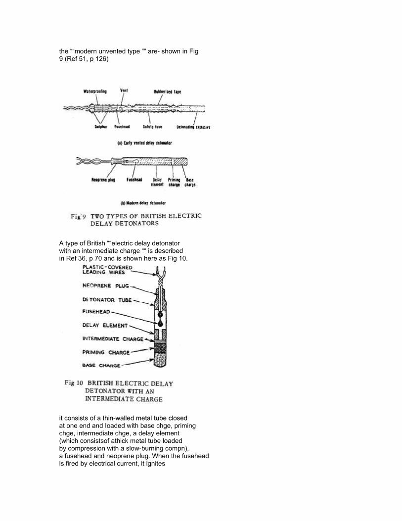
the ““modern unvented type ““ are- shown in Fig9 (Ref 51, p 126)
A type of British ““eIectric delay detonatorwith an intermediate charge ““ is describedin Ref 36, p 70 and is shown here as Fig 10.
it consists of a thin-walled metal tube closedat one end and Ioaded with base chge, primingchge, intermediate chge, a delay element(which consistsof athick metal tube loadedby compression with a slow-burning compn),a fusehead and neoprene plug. When the fuseheadis fired by electrical current, it ignites
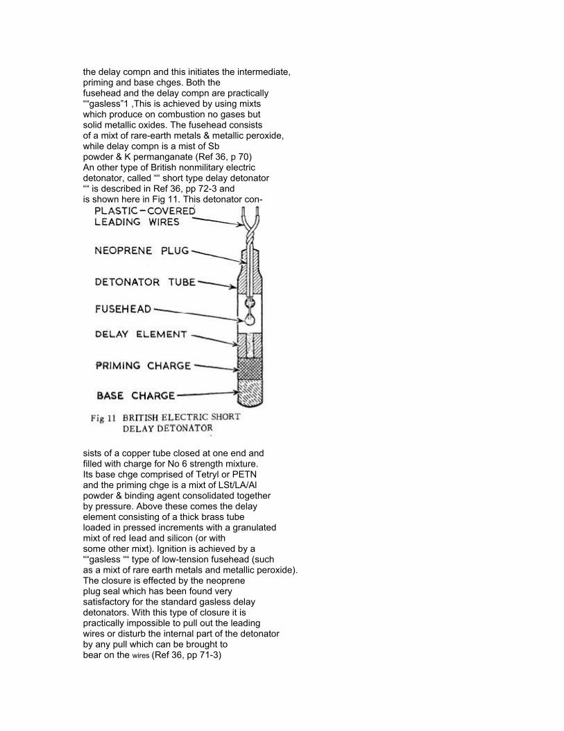
the delay compn and this initiates the intermediate,priming and base chges. Both thefusehead and the delay compn are practically““gasless”1 ,This is achieved by using mixtswhich produce on combustion no gases butsolid metallic oxides. The fusehead consistsof a mixt of rare-earth metals & metallic peroxide,while delay compn is a mist of Sbpowder & K permanganate (Ref 36, p 70)An other type of British nonmilitary electricdetonator, called ““ short type delay detonator““ is described in Ref 36, pp 72-3 andis shown here in Fig 11. This detonator con-
sists of a copper tube closed at one end andfilled with charge for No 6 strength mixture.Its base chge comprised of Tetryl or PETNand the priming chge is a mixt of LSt/LA/Alpowder & binding agent consolidated togetherby pressure. Above these comes the delayelement consisting of a thick brass tubeloaded in pressed increments with a granulatedmixt of red Iead and silicon (or withsome other mixt). Ignition is achieved by a““gasless ““ type of low-tension fusehead (suchas a mixt of rare earth metals and metallic peroxide).The closure is effected by the neopreneplug seal which has been found verysatisfactory for the standard gasless delaydetonators. With this type of closure it ispractically impossible to pull out the leadingwires or disturb the internal part of the detonatorby any pull which can be brought tobear on the wires (Ref 36, pp 71-3)

Ordinary delay detonators in Gt Britainare issued in series numbered from O to 10,the interval betw any two consecutive delaynumbers being 0.5 sec. Thus the NO O firesinstantaneously, No 1 fires 0.5 sec later,etc ( Ref 36, p 71)Short delay detonators standardized inGt Brit in 1956 number 15 and their periodsrun from O for No O to 700 milliseconds forNo 15. For No 1 it is 25 msec, for No 2-50,for NO 4-100, for No 10-345, etc (Ref 36,p 73 and Table 2, p 74)Firing characteristics of Brit electricaldetonators are given in Ref 51, p 121Devices similar to above electric delaydetonators are described in Ref 44, p B 188-L,under BLASTING CAPS and in Ref 48, ppD49-R & D50-L, under Delay Blasting Cap.The description includes two types of electricdelay caps of DuPont Co and a nonelectricde lay blasting cap (pB50-L]. Compositionalof various delay elements are given onp B52Fordham (Ref 51, p 127) states that acommon mixture for US delay elements consistsof Ba peroxide 85 & Se 15% and thatfor the manuf of millisecond delay detonators,faster burning compns are required suchas Si 30-50 & red lead (or Iead dioxide) 50-70%.Manuf of delay compns is described on pp 128-29, assembly on p 129 and design on pp 129-30of Ref 51. Ger delay compositions (Verzb”-gerungsverbindungen) and delay elements(Verz&gerungski5rper) are described in Ref 35, pp Ger33 & Ger 34Taylor & Gay (Ref 36, pp 62-4), discuss““principles of series ““ shot firing “t where theyexplain why the current needed to fire a seriesshould be greater than that required to firea single e Iectric detonator. If a uniform directcurrent is applied to a series of electricdetonators, before any one detonator can fire,the fusehead must be traversed by the currentfor a certain period of time (usually of theorder of milliseconds) during which time thebridgewire heats up to a temperature at whichthe sensitive compn of the fusehead ignitesand fires the detonator. The minimum timeis called the “’excitation time ““ and this isshown in Ref 36, p 63, as Fig 10, which isgiven here as Fig 12. After the fuseheadreceives the minimum amt of current therewill normally be a further small time lapsebefore the ignition spreads thru the fuseheadand communicates to the priming charge ofdetonator. This is the moment at which it
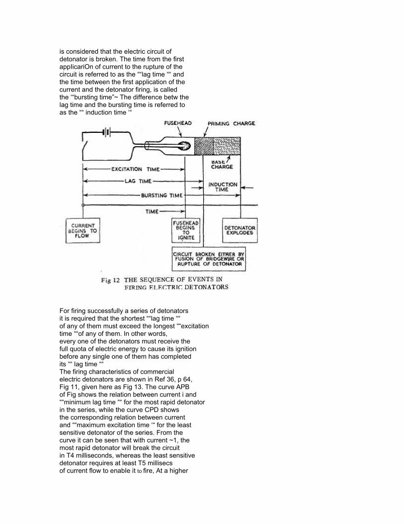
is considered that the electric circuit ofdetonator is broken. The time from the firstappIicariOn of current to the rupture of thecircuit is referred to as the ““lag time ““ andthe time between the first application of thecurrent and the detonator firing, is calledthe ‘“bursting time”~ The difference betw thelag time and the bursting time is referred toas the ““ induction time ‘“
For firing successfully a series of detonatorsit is required that the shortest ““lag time ““of any of them must exceed the longest ““excitationtime ““of any of them. In other words,every one of the detonators must receive thefull quota of electric energy to cause its ignitionbefore any single one of them has completedits ““ lag time ““The firing characteristics of commercialelectric detonators are shown in Ref 36, p 64,Fig 11, given here as Fig 13. The curve APBof Fig shows the relation between current i and““minimum lag time ““ for the most rapid detonatorin the series, while the curve CPD showsthe corresponding relation between currentand ““maximum excitation time ‘“ for the leastsensitive detonator of the series. From thecurve it can be seen that with current ~1, themost rapid detonator will break the circuitin T4 milliseconds, whereas the least sensitivedetonator requires at least T5 millisecsof current flow to enabIe it to fire, At a higher
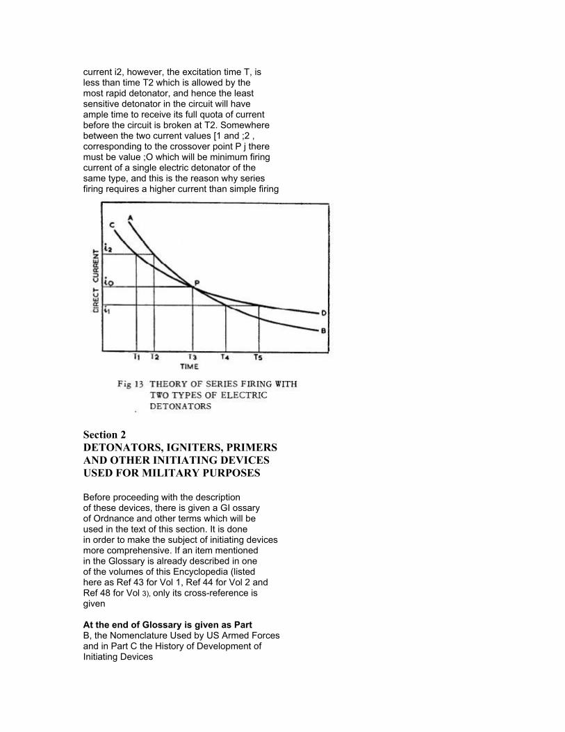
current i2, however, the excitation time T, isless than time T2 which is allowed by themost rapid detonator, and hence the leastsensitive detonator in the circuit will haveample time to receive its full quota of currentbefore the circuit is broken at T2. Somewherebetween the two current values [1 and ;2 ,corresponding to the crossover point P j theremust be value ;O which will be minimum firingcurrent of a single electric detonator of thesame type, and this is the reason why seriesfiring requires a higher current than simple firing
Section 2DETONATORS, IGNITERS, PRIMERSAND OTHER INITIATING DEVICESUSED FOR MILITARY PURPOSES
Before proceeding with the descriptionof these devices, there is given a GI ossaryof Ordnance and other terms which will beused in the text of this section. It is donein order to make the subject of initiating devicesmore comprehensive. If an item mentionedin the Glossary is already described in oneof the volumes of this Encyclopedia (listedhere as Ref 43 for Vol 1, Ref 44 for Vol 2 andRef 48 for Vol 3), only its cross-reference isgiven
At the end of Glossary is given as PartB, the Nomenclature Used by US Armed Forcesand in Part C the History of Development ofInitiating Devices
Section 2, Part AGlossary of Ordnance and Other TermsUsed in This Description of Ordnance Items
Activator (of a Land Mine). It was defined in Vol1, p A lO 1-L of Encycl (Ref 42) as a fuze, butactually it is a detonator-booster, which actsin conjunction with a firing device, as asecondary /uze which provides some A/Tmines with antilifting or booby trappingcapabilities. In TM 9-1940 (1956),“Land Mines”, pp 110-11 is describedActivator .M1 which is used in A/Tmines M6 & M15 series. The device isca 2 inches long and is made of a black plasticmaterial. It contains a detonator, has acylindrical unthreaded cup cemented to theopposite end of the body and contains a TetrYlbooster chge (See Fig 14). There is also ActivatorHE, M2 (RDX-loaded) (Compare with Fuze,Auxiliary, under Fuzes in Section 5, Part A)
Activator, Antitank Mine . It is defined inMIL-STD-444 (Ref 40a, p 2) as ““a nonmetallicitem designed to adapt a firing device toan antitank mine. It may be empty, inertfilled or explosive filled ‘“Actuator. See Explosive Actuator in thisGlossaryAircraft Ammunition. See Ref 43, p A384-RAmmunition. See Ref 43, p A383-L & Ref 40a,p8AP . Abbr for Armor-piercingA/P Abbr for AntipersonnelAT or A/T . Abbrs for AntitankAuxiIiary Detonator, See Detonator, Auxiliary

Baffle (Used in Delay Elements). When a primerof a delay element is initiated, a highvelocity jet (hot gases, slag particles, andfragments of the closure disk or cup) is projectedtoward the BkPdr pellet. The inertiaof these blast components is such as to causeundue penetration of the pellet’s surface therebydisrupting a portion of it and affecting thedelay time. Such condition is exceptionallyserious with obturated delays of small timemagnitude, say 0.01 see, where the impingementof these combustion products will completely‘d;srupt the very small pellet, givkgno significant delay. To combat this disruptiveforce, a ba//~e is employed. Baffles’have many forms, but all serve to absorb theenergy of slag particles and sealing devicefragments by deflecting them. An additionalfunction is to reduce the velocity of the hotprimer gases and ““ease ““ them across thesurface of the pellet. Baffles ate made of thesame material as delay element body in orderto reduce the possibility of electrolytic corrosion.Brass or Al alloys are usuaIly employed,and occasionally stainless steel. Thesize of the baffle is usually dictated by space
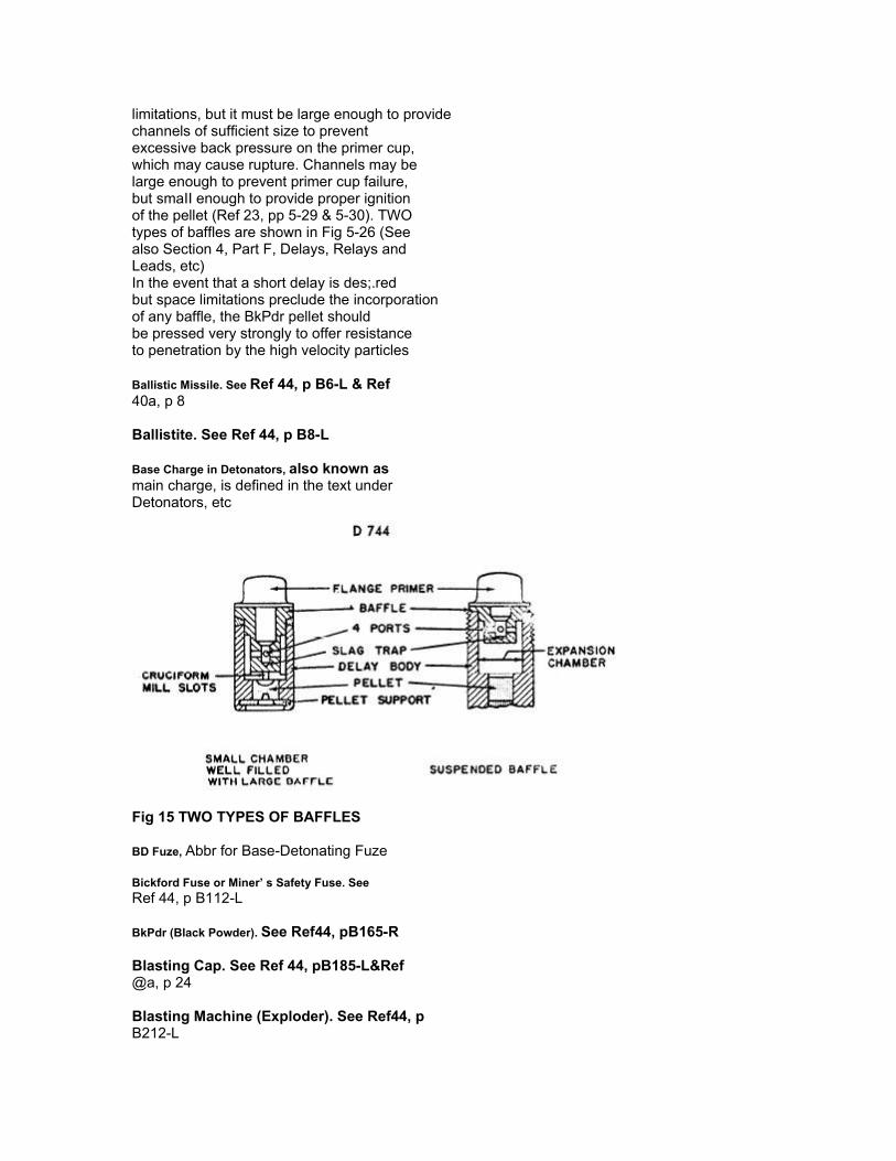
limitations, but it must be large enough to providechannels of sufficient size to preventexcessive back pressure on the primer cup,which may cause rupture. Channels may belarge enough to prevent primer cup failure,but smaII enough to provide proper ignitionof the pellet (Ref 23, pp 5-29 & 5-30). TWOtypes of baffles are shown in Fig 5-26 (Seealso Section 4, Part F, Delays, Relays andLeads, etc)In the event that a short delay is des;.redbut space limitations preclude the incorporationof any baffle, the BkPdr pellet shouldbe pressed very strongly to offer resistanceto penetration by the high velocity particles
Ballistic Missile. See Ref 44, p B6-L & Ref40a, p 8
Ballistite. See Ref 44, p B8-L
Base Charge in Detonators, also known asmain charge, is defined in the text underDetonators, etc
Fig 15 TWO TYPES OF BAFFLES
BD Fuze, Abbr for Base-Detonating Fuze
Bickford Fuse or Miner’ s Safety Fuse. SeeRef 44, p B112-L
BkPdr (Black Powder). See Ref44, pB165-R
Blasting Cap. See Ref 44, pB185-L&Ref@a, p 24
Blasting Machine (Exploder). See Ref44, pB212-L
Blend. Nitrocellulose (NC) contg 13.15 to13.25% N. See Ref 44, p C103-L
Bomb. See VOI 2 of Encycl (Ref 44), pB225-Rff
Booby Trap. See Ref 44, p B225-R
Boom. An extension of an ordnance item
Boom Igniter. Such igniters are shown oncutaway illustrations of 90mm HEAT CartridgeM348Al and 105mm HEAT CartridgeM341 described in Section 3, Subsection D,under Primers and also in Ref 52, p 3-26.The Figs show that percussion primersof these cartridges are threaded into the finassembly of the tail boom. A recess holdsthe 1 st ignition cartridge. Then comes avent for the transmission of the cartridgegas to the ““ boom ignition cartridge “1 Thisextra cartridge is needed for proper de flagrationof propellent charge (Ref 55)
Booster. See Ref 44, p B243
Bullet. See Ref 44, p B324-R
Burster. See Ref 44, p B364-L
Bursting Charge or Main Charge. See Ref 44,p B364
Cannon. See Ref 44, p C26-L and Ref 40a,p 23. The following slightly different definitionis given in Ref 45f, p 2-1: ““A cannon(general) is a weapon conforming to the generalgun definition, that is provided with structure(mount) for mechanical support duringfiring, and that has a bore diameter exceedingthe limit assigned to small arms. (The smallarms bore limit is presently administrativelyset at 3i)mm). The general category of cannonis further divided, in accordance with ballisticcharacteristics and use, into guns, howitzers,mortars, and recoilless weapons “1 A““ cannon ““ (specific), is defined in Ref 45f,p 2-5, as the term used to denote the “shooting part of a complete weapon (gun ,howitzer, mortar or recoilless weapon) comprisingonly the tube and breech structuresand such mechanism as is supported thereonfor opening and closing the breech and firingthe propelling charge
Cannon Propellant. See Ref 44, p C29-R
Carbine. See Ref 44, p C51-L & Ref 43, p 4-6
Cartridge. See Ref 44, p C70
Charge (Explosive Charge). See Ref 44, p C150
Cluster. See Vol 3 of Encycl, p C351-L
Collodion Cotton (abbr CC). See Ref 44, pC103, under CELLULOSE NITRATES. Alsoknown as Pyroxylin
Complete Round of Ammunition. See Ammunition,Complete Round in Ref 43, p A385-L
Composite propellants . See Ref 48, p C464-L
Cord, Detonating or Cardeau. See Ref 44, pC529-R
Cordite . See Ref 48, p C531-R
Cyclonite. See RDX in this Glossary
DADNPh . Our abbr for Diazodinitrophenol
DDNP. Abbr given in TM’s for Diazodinitrophenol
Deflagrating Explosives. See Ref 48, ppD38.R and D107-L. Known also as LowExplosives (See in this Glossary)
Deflagration. See Ref 48, p D38-R
DEGDN.. Our abbr for Diethyleneglycol Dinitrate
Delay. See Ref 48, p D49 and in this Vol,Section 4, Part F
Delay Blasting Cap. See Ref 48, p D49-R
Delay Charges; Delay Compositions or DeloyPowders . See Ref ,48, p D50-Lff and Section 4,Part F in this Vol
Delay Detonators . See in this Vol, Section 4,Part F
Delay Explosive Train. See in Ref 48, p D53.Land in this Vol, Section 4, Part F
Demolition Bangalore Torpedoes. See Ref 44,p B16.R
Demolition Explosives. See Ref 48, p D56.R& Ref 53
Demolition Kit or Unit. See Ref 48, p D61-L
Demolition Snakes. See Ref 44, p B17
Destructor. See Ref 48, p D92-R
Detonating Cap. Same as Blasting Cap
Detonating Cord . See Cord, Detonating in Ref48, p C529-R and Detonating Cord or Fuse inRef 48, p DI03
Detonating Explosive. See Ref 48, p DI07-Land also High-Explosive in this Glossary
Detonation. See in this Vol under DETONATION(AND EXPLOSION)
Detonator (Commercial or Nonmilitary); SeeSection 1, Part C in this Vol
Detonator, Auxiliary. The following explanationis given by odierno in Ref 45d, p II:“- In the development of some items in thepast, prior to the use of electrical fuzes forPIBD (point initiated base detonated) fuzes,an explosive component known as an auxiliarydetonator was used. This detonator resembledflanged lead cup in outward appearance,however, it was longer, Iarger in diameterand incorporated a shape charge on theoutput end. The auxiliary detonator was usedto jump the gap from the base of the fuze downthrough a hollow tube in the shell to a Tetrylor RDX pellet in the bottom of the shell. Thiswas acceptable, however, it was not as efficientas the electrical PIBD F uze, becauseof alignment problems, time of functioning, etc ““
Detonator, Delay. See in this Vol, Section 4,Part F
Detonator, Electric . See Section 3, Part Eand Section 4, Part D
Detonator, Flash. See Section 3, Part Eand Section 4, Part D
Detonator-Primer. See Section 3, Parts D &E and in Section 4, Parts D & E
Excerpted from The Enyclopedia of Explosives and Related Items Vol. 4