developing a multicopter uav platform to carry...
TRANSCRIPT
University of Western Australia Perth, Western Australia
DEVELOPING A MULTICOPTER UAV
PLATFORM TO CARRY OUT RESEARCH INTO
AUTONOMOUS BEHAVIOURS, USING ON-
BOARD IMAGE PROCESSING TECHNIQUES
A thesis in partial fulfilment of the
requirements for the degree of
BACHELOR OF ELECTRICAL and ELECTRONIC ENGINEERING
By
Rory O’Connor
2013
1
35 COOLGARDIE ST
SUBIACO WA 6008
1/11/2013
The Dean
Faculty of Engineering Computing and Mathematics
The University of Western Australia
35 Stirling Highway
CRAWLEY WA 6009
Dear Sir
I submit to you this dissertation entitled “DEVELOPING A MULTICOPTER UAV PLATFORM
TO CARRY OUT RESEARCH INTO AUTONOMOUS BEHAVIOURS, USING ON-BOARD
IMAGE PROCESSING TECHNIQUES” in partial fulfilment of the requirement of the award of
Bachelor of Engineering.
Yours Faithfully
Rory O’Connor
2

“Once you have tasted flight, you will forever walk the earth with your eyes turned skyward, for
there you have been, and there you will always long to return.”
ʊ Unknown, attr. Leonardo da Vinci
I. ABSTRACT
In conjunction with CIIPS and fellow students, a hexacopter UAV was developed to carry out
practical semi-autonomous on-board image processing functions. In this project, the process of
developing the platform, for research and development of autonomous UAV applications is
investigated and the findings are reported.
Using off the shelf components, the research focusses on utilising a Raspberry Pi computer to
process live image data captured from an on-board camera, to identify and isolate nearby objects
of interest. The position and inertial data of the UAV is also measured in real time, to provide a
reference for interpreting the image data. Furthermore, the Raspberry Pi was programmed to
generate intelligent flight responses in reaction to the data recovered from the camera and other
sensors. This process controls the desired reaction of the UAV to the objects identified in the
nearby environment.
By incorporating these algorithms together with autonomously controlled flight trajectories, the
UAV was successfully programmed to carry out simple track-and-follow tasks in a robust
manner without operator assistance or interference.
3

The results of this image based feedback control can be used to assist further development of a
wide variety of functions that may be implemented into other UAV platforms. In turn, these
functions can be tailored to suit a host of relevant real world applications, depending on the
requirements of the operator.
This thesis should offer an insight into the autonomous capabilities of modern UAV platforms to
engineering students and research professionals who are interested in starting a similar project.
UWA engineering students doing their honours research next year have arranged to continue the
work that began as part of this thesis. The platform that was developed will no doubt serve as a
robust system to further study and improve upon the results achieved in this thesis.
4
II. ACKNOWLEDGEMENTS
Supervisors Thomas Braunl and Chris Croft
Fellow robotics students Chris Venables and Thomas Drage
Head UWA Electronics Technician Jonathan Brant
PerthRC staff
Pierre Raufast, developer of Raspberry Pi programs
All of my family, friends, and loved ones
who supported me this year
For your wisdom, guidance and support
in this project, thankyou.
5
III. GLOSSARY
AV Audio-Visual
CPU Central Processing Unit
EM ElectroMagnetic
ESC Electronic Speed Controller
FC Flight Controller
FM Frequency Modulation
FPV First Person View
HSV Hue, Saturation, Value (Describing the colour of a Pixel)
IMU Inertial Measurement Unit
DJI A multicopter systems manufacturer
GCS Ground Control Station
GPS Global Positioning System
GUI Graphical User Interface
LCD Liquid Crystal Display
MEMS MicroElectroMechanical Systems
NAZA A multicopter flight controller made by DJI
PC Personal Computer
RC Radio-Control
RF Radio Frequency
RGB Red, Green, Blue (Describing the colour of a Pixel)
RPi Raspberry Pi computer
Rx Frequency Modulated Radio Receiver
Tx Frequency Modulated Radio Transmitter
UAV Unmanned Aerial Vehicle
USB Universal Serial Bus
VTOL Vertical Take-Off and Landing
WiFi IEEE 802.11b Wireless Communication Technology (Wireless Fidelity)
6

IV. INTRODUCTION
The field of unmanned aerial vehicles has, within the last few decades, emerged as a tangible and
utility-focused area for university students worldwide to explore and develop robust robotics
systems[1-3]. For longer still, the field has been an important element of military intelligence
research and development. Publicly, radio controlled aerial vehicles have been popular for
several decades, however improvements in technology have only recently allowed for the
possibility of robust, autonomous aerial vehicles built for civilian applications at a budget
suitable for an individual or small team[4, 5].
Technological improvements such as lithium polymer batteries, which have a higher specific
energy density than nickel metal hydride or sealed lead acid batteries, and offer more favourable
packaging capabilities, allow us the possibility of improved flight times and performance[6-9].
Improvements in the embedded systems to govern the vehicles behaviour, such as the open
source Arduino chips and projects, Raspberry Pi computer-on-a-chip, as well as others, have
allowed for an affordable platform to program autonomous piloting systems for such
vehicles[10].
With a robust control algorithm, to manipulate on-board data measurements such as altitude and
velocity, combined with image capturing and computing systems, an autonomous aerial vehicle
has the potential to provide a highly versatile solution to problems requiring 3D mobility,
stability, and a superior visual perspective of all ground objects[3, 11, 12].
Defence and rescue - based applications such as coastal patrols to spot sharks and people in need
of assistance, or a cheaper and safer alternative to helicopters for bushfire monitoring, are some
possible applications of the emergent technology. Industrial companies may use the technology
7

to survey aerial viewpoints of areas in real-time, especially in dangerous environments such as
open-pit mines, or oil rigs.
V. LITERATURE REVIEW
This literature review will discuss many of the terms and definitions of the physical elements
associated with this thesis. The review will also consider existing areas of research related to this
project, as well as a discussion about the limitations of existing research, and an argument for the
relevance of the research proposed for this thesis.
UAVs and VTOL
The term UAV stands for Unmanned Aerial Vehicle, and is defined by the US
Department of Defence as: “ ...powered aerial vehicles sustained in flight by aerodynamic lift
over most of their flight path and guided without an on-board crew”. This characteristic was the
most obvious to consider for the type of vehicle to use in the project, to ensure that the vehicle
could actually be flown and tested by students.
Almost as important as this, was the requirement that the vehicle be able to both take-off and
land vertically, without the need of a runway; these craft could theoretically land on an area just
larger than its own footprint. This capability, abbreviated to VTOL (Vertical Take Off and
Landing), affords functionality within diverse environments that may only offer small areas to
setup, launch and then land the UAV system. VTOL functionality increases the usefulness of
UAVs, as well as mitigating much of the potential for damages associated with a failed landing.
For the purposes of this report, the term “UAV” will refer only to the subset of these craft that
have VTOL functionality.
This class of vehicle presents many benefits over typical manned equivalents in their utility at
carrying out aerial tasks. The human pilot operating inside typical aerial vehicles such as
aeroplanes and helicopters assumes a risk to his or her life by the danger associated with a
potential crash from a great height and at great speed. Additionally, these craft must be designed
8
with the comfort and wellbeing of the pilot and crew in mind, necessitating equipment and safety
systems such as seats, flight control interfaces, oxygen supplies, ejection seats etc. Such systems
require additional volume, additional mass, and demand unnecessary power consumption from
the vehicle, while not inherently improving the flight characteristics of the vehicle. In fact, such
systems, in comparison to UAV equivalents, reduce the efficiency of the vehicle while
increasing the cost associated with operations.
For operations such as aerial surveying, where the vehicle is not used to transport people or
equipment, the efficiency gained by utilising UAVs over conventional manned technologies
allows for significantly longer flight times. Additionally, the systems are cheaper, pose a far
lower risk to the operator, and can carry out many useful functions autonomously, such as
waypoint navigation using GPS. They can also work in areas that may be unsafe for human
presence, such as sites of nuclear fallout. These factors contribute to the growing interest within
a wide variety of industries in Australia and Worldwide, towards using UAV technologies to
develop solutions that require an aerial perspective.
A limitation to UAVs compared to piloted craft, is that the UAV requires a very robust electronic
autopilot to maintain control of the vehicle. Standard navigational autopilot systems are currently
available for these craft using inertial measurement and GPS. However, a level of control that
reflects intelligent, real-time observation of and reaction to visible objects within the field of
view of the aircraft, is currently a functionality that requires the input of a human pilot from the
ground station.
AEROFOILS
Almost all UAVs move by generating thrust by spinning one or more sets of rotor blades.
The blades are a special shape called an aerofoil. An aerofoil generates a pressure gradient
between its top and under sides when it moves in the +X direction through a fluid, such as air.
The pressure is lower on the top side than the underside, so the aerofoil experiences a net force in
the +Z (vertical) direction to reach equilibrium. This effect is known as aerodynamic lift.
9

ROTOR BLADES AND ROTOR SETS
A rotor set is composed of n identical aerofoils, called blades, attached from one end to a
common rotating shaft. The relative position of the blades is rotated by 360/n degrees. When the
shaft is rotated about the common axis and in the correct direction, the blades generate
symmetrical lift, and the rotor set experiences a force that pulls it upwards. The circular path a
rotor set forms when rotating is referred to as the rotor plane.
HELICOPTERS
Helicopter-craft are the most commonly seen vehicles that have VTOL functionality,
featuring a single horizontally aligned rotor-set to produce thrust vertically, and a smaller
vertically aligned rotor-plane at the tail end to produce thrust horizontally. The lift generated
from the main rotor spinning will counteract the force of gravity on the vehicle. When the lift
force is equal to the weight of the helicopter, the helicopter can hover. The torque produced by
the spinning rotor is countered by a rotation of the helicopter hull in the opposite direction to the
rotor set. The horizontal thrust produced by the rotor at the tail end of the helicopter can be
increased or decreased in order to yaw (rotate around gravitational axis), or hold the bearing of
the vehicle steady [13].
The main rotor of a helicopter is also actuated by a swash plate, which makes small adjustments
to the angle of the rotor plane relative to the hull. Forwards and backwards adjustments are
called pitch adjustments, for example 'pitch forward'. Left and right adjustments are called roll
adjustments. Additionally, the collective pitch of the rotors sets can be increased or decreased to
adjust the angle of attack of the rotor blades, to increase the amount of thrust generated by the
rotor set.
Model helicopters present suitable flight capabilities for this project, however this platform was
not chosen for several reasons. The mechanical complexity of helicopters makes them relatively
expensive to buy and repair compared to the multicopter platforms considered. Additionally,
larger model helicopters suitable for this project would present more risk to nearby operators due
to the larger size of the rotors.
10
MULTICOPTERS
Multicopters are helicopter-like vehicles that use multiple sets of rotors, usually mounted
in a co-planar formation, to achieve lift. These craft can manipulate the same four typical
controls as helicopters: yaw, pitch, roll and thrust [2, 13-16].
The main advantage multicopter vehicles have over helicopters is that the rotor sets in a
multicopter spin in opposite directions to counteract the torque that the frame experiences. When
a clockwise spinning rotor and a counter-clockwise spinning rotor have the same rotational
velocities, the torque each rotor produces is equal and opposite to that produced by the other.
When the rotors are mounted to a frame, these torques cancel each other out, and the frame
experiences no net torque, and will not spin in free space. Rotation can be achieved when one of
the motors is sped up relative to the other. Opposite rotation is achieved by switching the choice
of motors to speed up and slow down.
Thus, all of the thrust produced by the rotors on a multicopter contribute towards lift. In contrast,
helicopters must generate thrust perpendicular to the axis of lift in order to govern yaw. Since the
thrust from the tail does not act to lift the vehicle, the energy taken to generate this thrust is
wasted[13].
There are many choices for multicopter frame and motor layout. The layout can incorporate any
number of rotor/motor sets mounted to the vehicle frame, though price, size and processing
considerations usually limit the maximum number to eight motors. There is a popular video on
YouTube which demonstrates an exception to this rule, featuring a multicopter with 16 sets of
rotors (a hexadeca-copter) that can lift an adult human pilot[17].
The motors are usually mounted rigidly to the frame, though some designs feature rotating motor
mounts, actuated by control signals sent to servo motors. This mechanic allows for certain thrust
vectoring manoeuvres not afforded by static motor mounts, though it also introduces additional
mechanical complexity, as well as power consumption by an actuator that does not generate lift
(as with a helicopter tail rotor). Servo vectored motor mounts are usually used on bi- or tri-
11

copters, since these craft have only two or three sets of rotors, and cannot control pitch, roll and
yaw without at least four distinct actuators. Some of the more popular styles of multicopter used
by hobbyist pilots currently are described in further detail below.
1) BICOPTERS: Bicopters use two coplanar rotor sets to produce lift, powered by two
brushless motors. Two more servo motors actuate these brushless motors around the common
central axis, to change the thrust angle of each rotor set independently. These four motors can be
controlled with a multicopter FC to govern the thrust, yaw, pitch and roll of the bicopter.
2) TRICOPTERS: Tricopters use three coplanar rotor sets to produce lift, powered by
three brushless motors. Furthermore, a single servo motor controls the thrust angle of the tail
rotor. The three rotor sets can be driven at different RPM values to control the thrust, pitch and
roll of the tricopter. The thrust vector of the tail rotor can be manipulated with the servo motor,
and this action controls the yaw of the tricopter.
3) QUADCOPTERS: Quadcopters use four rotor sets to produce lift, powered by four
brushless motors[2]. In contrast to bi and tri-copters, the rotor sets of a quadcopter may be
mounted in several distinct formations, and are not always co-planar.
The most common configuration is the coplanar 'x' shape. This design uses symmetrically
mounted rotor sets and has symmetrical pitch and roll flight characteristics. This configuration is
identical to the '+' configuration, except for a 45 degree rotation of the dedicated 'forward'
direction.
Another popular configuration of the quadcopter is the v-tail design. This type of configuration is
similar to the 'x' type at the forward end, featuring two co-planar rotor sets. However at the
tailing end of a v-tail, the two rotor sets are mounted at an incident angle to the co-planar set,
forming a "V" shape. The two tail rotors will produce thrust both downwards to provide lift, as
well as outwards from the tail end to provide extra control authority when carrying out yaw
manoeuvres.
12

Finally of note is the less common Y4 configuration. This design is similar to that of the v-tail
and 'x', with two coplanar rotor sets at the front. The two rotor sets at the rear of the Y4 design
are mounted coaxially. In this configuration, the differential between the two rotor sets at the rear
of the vehicle produce net torque which can control yaw. The Y4 implementation suffers the
downside of propeller wash between the two rear rotors. This effect manifests as a pocket of air
generated between the rear rotor sets that is higher pressure than atmospheric air. The energy
powering this divergence of pressure is wasted, since the effect does not generate extra any extra
lift for the multicopter.
4) HEXA- AND OCTO- COPTERS: Hexacopters and octocopters have six and eight rotor
sets respectively. These sets, as with the quadcopter ‘x’ configuration, are mounted
symmetrically around the centre of the frame. These extra motors offer an important additional
function over multicopters with fewer rotor sets, due to the capability to lose power to one motor
and still have sufficient power-out to control the UAV[18]. This functionality is maintained as
more co-planar, symmetrically mounted rotor sets are incorporated into multicopter designs,
producing decacopters, dodecacopters and even hexadecacopters. However, adding more rotor
sets to a multicopter also equates to a higher system cost and more pieces of equipment on-
boards that may fail.
5) OTHER MULTIROTORS: Many hybrid designs have been investigated that
incorporate fixed wing surfaces with multiple actuated rotor sets[19]. These designs offer the
benefit of VTOL functionality as well as low-power gliding functionality. However, the structure
and layout of these aircraft are non-trivial, and were considered too complicated for this project.
POWER SYSTEMS
Hobbyist multicopters, unlike equivalent RC aeroplanes and helicopters, have only been
designed using electrical motors[20]. Brushless outrunner motors are regarded as the best motor
choice for multicopters. These motors require electronic speed controllers (ESCs) to supply three
phase power to the motors from a DC source. The magnitude of the power delivered to the motor
13
is based on a single input signal provided to the ESC. This signal is composed of a pulse width
modulated (PWM) waveform, and is very similar to the type of signal that is used to control a
servo motor.
Lithium polymer ion batteries are the regarded as the best choice for hobbyist multicopter
projects due to their high energy density, due to the importance of a high thrust to weight ratio in
aerial vehicles[6, 9].
FLIGHT CONTROL SYSTEMS and INERTIAL MEASUREMENT
Embedded flight controller (FC) technology, governing UAV stabilisation, has improved
greatly over the past few decades. Originally, flight ‘controllers’ for model helicopters were
simply a direct routing of the RC signals from the pilot. With a mechanically sound model
helicopter, stability can be achieved by manipulating analog controls on the RC transmitter (Tx),
and feeding the signal through to the RC receiver (Rx) and directly to the relevant actuator (for
example the main motor/rotor or the swashplate). No electronic processing is necessary to
stabilise and fly the helicopter when the pilot has had sufficient experience at the controls[13].
However, many model helicopters feature the use of a gyro to measure and control the rate of
yaw. This instrument is used simply to measure the torque that is produced by changing of the
rotor speed associated with carrying out manoeuvres (for example ascending/descending with
constant heading). Measurements are then processed electronically, to automatically adjust the
tail rotor thrust. This thrust counters the rotation that the helicopter experiences from the main
rotor changing speed. As cheaper piezoelectric and MEMS -based inertial measurement
technologies replaced larger and more expensive mechanical gyros, incorporating these units into
model helicopter design became a standard.
Multicopters, in contrast to helicopters and aeroplanes, must have a FC incorporated into the
design. Multicopters are aerodynamically unstable and constant minor corrections must be made
to combat disturbances to the orientation of the vehicle[2, 21].
14

Flight controllers require information describing the inertial state of the UAV to provide stable
feedback. The changes in orientation and position of the UAV are measured using an inertial
measurement unit (IMU).
Simple multicopter FC devices use a three-axis gyroscopic IMU. The three axes measure the
pitch, roll and yaw of the UAV. This level of control will theoretically maintain the angle of the
UAV relative to the ground, though the drift associated with gyros means stabilisation to a
prescribed angle relative to the ground cannot be achieved. When flying in this mode, the pilot
must determine the appropriate inputs to keep the UAV flat and stabilised. This flight mode is
more difficult to learn and master, however it offers perhaps the best mechanics for acrobatic
flight[22].
More common FCs add to the three-axis gyro sensor with another three-axes set of linear
accelerometers. Accelerometer readings will not drift over time, and give the FC the ability to
measure the exact orientation of the UAV. With this information, the FC can maintain the rotor
plane parallel to the force of gravity, achieving a flat, stable hovering state autonomously.
Figure
15

Additional features offered by more expensive FCs include magnetometers to measure exact
compass bearing of the UAV, barometers to measure flying altitude by the change in air
pressure, and GPS to measure the position of the vehicle in open outdoor settings.
These sensors all measure inertial data, which is processed by the FC. The FC then determines
distinct signals for each motor that will maintain the UAV in the desired position, heading and
altitude autonomously[11, 12, 22, 23].
Some FC models offer output signals that will govern the position of a servo controlled camera
gimbal. Powered camera gimbals require inertial information to control the position of the
camera, so an IMU is necessary for operation. Since most FC models feature advanced IMUs,
the information these units measure can be used for both flight and gimbal control [14].
TRANSMITTER/RECEIVER SETS
The communication channels between the pilot and UAV system are physically
accomplished by sets of equipment described as transmitters (Tx) and receivers (Rx). These
devices respectively encode and transmit, or receive and decode, digital information over
electromagnetic frequencies.
Hobby and toy grade RC aircraft require one Tx/Rx set. The Tx is built into the handheld
controller, which encodes movement from the fingers of the pilot into several channels of flight
control data. Each channel is encoded as a scalar value based on the position of the interface,
which is usually composed of two joysticks each with two dimensions of movement. More
advanced Tx sets also feature buttons, knobs and switches, as well as an LCD screen as part of
the controller interface.
The Rx receives the signal from the Tx and decodes the various channels into digital outputs.
Each channel is physically connected to either the FC, or in the case of simpler RC toys, directly
to servo motors or electronic speed controllers.
16
Other Tx/Rx sets are often utilised in UAV systems. Foremost is in the transmission of live video
data back from the UAV. When using this visual feedback exclusively to operate the UAV, the
pilot is said to be flying 'first person view', or FPV.
Another Tx/Rx set is sometimes used to transmit telemetric data from the UAV back to the pilot
or GCS. This telemetric data can include the GPS position, altitude, heading, battery levels and
other on-board measurements of the UAV.
Each Tx/Rx set is matched to the same EM frequency. Other similar Tx/Rx sets that operate on
the same frequency may cause interference between the sets when operated in close proximity.
Usually the systems can be bound to a selection of distinct bandwidths within the frequency,
mitigating some of this interference.
A simple solution is to use Tx/Rx sets with different operating frequencies. For example, the RC
controller that was used in this project transmits flight control information over the 2.4GHz
frequency band. The video transmitter on board the UAV uses the 5.8GHz frequency band.
Therefore the video receiver should not be impacted by close proximity to the RC transmission,
and the RC receiver will not be impacted by proximity to the video transmission.
This being said, each electronic component will generate some small EM noise around itself in
normal operation; all internal currents produce a magnetic field.
ADDITIONAL SENSORS
Image processing, though perhaps the most difficult to implement, was only one of many
sensor-based functionalities that were considered as goals. In addition to image processing, the
vehicle would need a global positioning system (GPS) in order to navigate in open outdoor
environments. GPS can identify the position of the vehicle, and can process this information into
data describing the velocity of the vehicle.
Other sensor systems were also considered, such as echolocation of nearby objects using
sonar. This functionality has been implemented into UAV systems previously, mainly for
17

measuring and controlling the height of the UAV relative to the ground. Though possibly very
useful for safety, this functionality was not investigated as part of this project since this
technology has already undergone thorough research.
GROUND CONTROL STATION
The successful flight of UAVs requires an appropriate ground control station (GCS). This
element can be as simple as a pilot with the RC transmitter, flying the UAV line-of-sight. More
complicated setups can include:
x Multiple receivers of various frequencies.
x Large, immobile antennae for the receivers.
x Portable TV screens, to view the received video feed.
x Generators and large capacity batteries, to power the electronic equipment.
x Computers to interpret and visualise received telemetry data.
x Spare batteries and battery charging units.
The GCS is essentially composed of all of the hardware that the pilot requires to operate the
UAV from the ground.
IMAGE PROCESSING
This is the process by which digital video cameras capture image information, which is
delivered to a computer that can apply filtering and analysis to the data. The process can be used
for many different applications, from colour detection to facial recognition in real-time. This
type of processing requires a powerful CPU, and until a few years ago, was difficult to achieve
on miniature computer platforms. However, using the OpenCV library
VI. MAIN REPORT
18
The purpose of this project is to study image-based autonomy in UAV platforms. The motivation
of this thesis as a University report, is to aid further study into the field of UAV robotics, by
demonstrating the process by which such a vehicle can be developed, and by presenting results
that increase the knowledge and understanding of the capabilities of these vehicles.
The sight of a seagull flying in circles above somebody as they walk at beach, hoping to spot a
free snack accidentally crumble away from their lunch, is common and easy idea to imagine. The
sight of an UAV autonomously tracking a moving object is something that until recently was
only seen in science fiction movies and perhaps secret high-tech military operations. This idea is
striking to imagine, and has captured the imagination of engineers, scientists and children alike.
To be able to see this in first person is inspiring, and encourages new ideas for practical
applications far beyond the entertainment of hobbyists.
UAVs have the potential to be a highly versatile autonomous platform that can address problems
requiring 3D mobility, coupled with a birds-eye perspective. By producing a robust control
algorithm to manipulate the position of the UAV, using on-board inertial data measurements,
combined with image capturing and processing systems, this platform can be achieved.
This thesis is intended to show readers of all disciplines some of the potential capabilities of this
technology, in the hope that they may be inspired to use this knowledge to assist in their field of
investigation.
As part of CIIPS (Computational Intelligent Information Processing Systems), and under the
supervision of Professor Thomas Braunl and Mr Chris Croft, students were tasked research,
design and then produce a new robot that incorporates UAV technology with image processing
autonomous functionality. Initially, the problem was to be defined.
PREVIOUS RESEARCH
19

After studying the results of existing research that had utilised image processing to
autonomously control UAV technology, it was clear that many interesting and useful results had
already been established. Two particular methods had been most popular to investigate.
One of these methods involves capturing video images from a UAV, then transmitting
the image information to a GCS before processing. The GCS has a receiver (often WiFi), and a
PC powerful enough to process the image information into relevant state information about the
UAV (eg check if the UAV can see a predefined target with its camera)[15].
The other method does not involve an on-board camera at all, but instead uses multiple
stationary cameras mounted around the environment dedicated to UAV functionality. The
cameras each feed their view of the UAV to a GCS that can process the images into state
information about the UAV (eg position, bearing, velocity etc).
In both of these methods, the GCS, after processing the image data, would have
autonomously decided a set of commands to transmit back to the UAV. These commands will
either modify or maintain the control signals that govern the flight mechanics of the vehicle, in
order to achieve the desired behaviour[11, 15, 16, 24, 25].
These two methods have been carried out in various configurations to produce exciting and
useful results. However, downsides were identified to both of these methods[15, 16, 25]. The
requirement for a UAV to be within the field of view of stationary cameras to achieve autonomy,
means that the range of operation of the vehicle is severely restricted. The environment that these
projects are carried out within must be carefully set up and calibrated, making the system
difficult to incorporate into solutions for industries that may seek autonomous UAV functionality
in a variety of different locations.
Furthermore, the systems that capture video on-board, before transmitting that data back
to a GCS for processing, as well as the multiple stationary cameras method, rely on the GCS to
govern the position and movement of the UAV. Thus, these UAV systems can only behave
20
autonomously within the confines of the transmission of the control signal back to the UAV from
the GCS [15, 16].
The integrity of the link between the UAV and the GCS is essential in these projects, and
achieving autonomy as distance between these components increases becomes slower, and
eventually impossible as the WiFi signal degrades. In the event of the UAV in these systems
losing the control signal from the GCS, and without any contingency in place to take control in
this incidence, the UAV will crash to the ground.
A NEW APPROACH
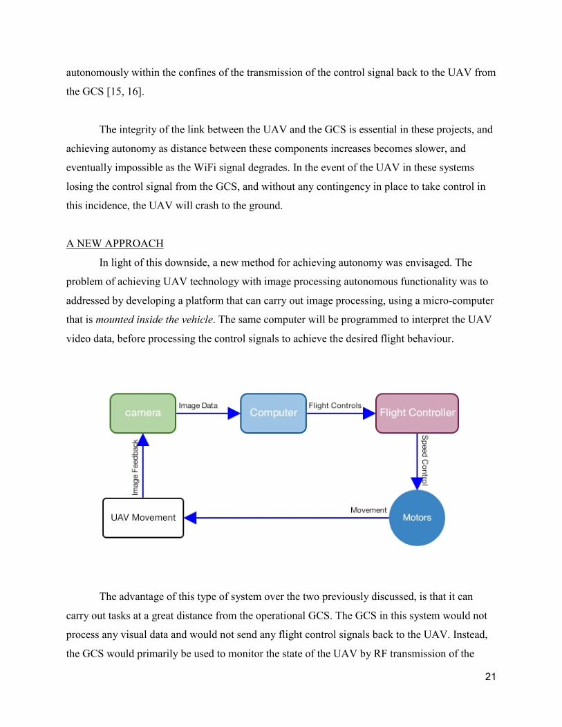
In light of this downside, a new method for achieving autonomy was envisaged. The
problem of achieving UAV technology with image processing autonomous functionality was to
addressed by developing a platform that can carry out image processing, using a micro-computer
that is mounted inside the vehicle. The same computer will be programmed to interpret the UAV
video data, before processing the control signals to achieve the desired flight behaviour.
The advantage of this type of system over the two previously discussed, is that it can
carry out tasks at a great distance from the operational GCS. The GCS in this system would not
process any visual data and would not send any flight control signals back to the UAV. Instead,
the GCS would primarily be used to monitor the state of the UAV by RF transmission of the
21

computer GUI in AV format, as well as activate or deactivate various autonomous functions
using a RC transmitter. By eliminating the WiFi connection from the real-time control loop, the
integrity or even implementation of a WiFi system on-board the UAV is no longer essential.
In reality, practical and safety considerations will always necessitate a wireless
connection from the UAV to the GCS during operations. However, without the requirement to
transmit data back and forth to the GCS to maintain autonomy, the system should in theory
operate at any distance from the GCS without loss of operational speed or degradation of flight
control. In addition, this new system could operate safely and successfully within the presence of
interference from other sources RF sources.
DEFINING THE GOAL
With this new approach, a specific goal was to be set and undertaken. Inspiration from
the embedded systems work carried out within CIIPS led to the development of the goals for this
platform. Several projects carried out under the supervision of Prof. Thomas Braunl, including
the EyeBots series, had already shown strong on-board image processing functionality.
UWA Embedded Systems (ELEC2303) students investigate image processing autonomy using
the EyeBot. Using a camera mounted at to the forward axis of the robot, the image data is
processed to identify a red object within the cameras field of view. This processed data is then
used to navigate the robot towards the object for further interaction and functionalities.
This process, to autonomously identify and track a red object, using an onboard camera and
onboard image processing, was the main element of the goal that was to be achieved by this
platform. The complete practical goal of this thesis was to build and program a UAV that is able
to be deployed in a variety of areas and carry out autonomously identify, track and follow a red
object.
The long term goal of this thesis is to begin work on a platform that can be used by other UWA
students in the future to further develop UAV robotics, and to gain the benefit of practical
investigation into this subject.
22

UAV SYSTEM DESIGN
This section describes the components that were chosen to fulfil the particular hardware
requirements for this project, and offers explanations for why these components were chosen.
Initially the components that govern the information processing systems of the platform are
described, followed by the remaining physical and mechanically important elements.
Two types of options for supplying the required equipment were utilised. Buying parts from
local suppliers, such as Perth RC, Stanbridges etc., offers the benefit of gaining access to the
equipment immediately. In addition, any problems or defects can be addressed by the supplier
locally, saving time associated with returning faulty parts by mail and receiving replacements.
Some pieces of equipment however, were only available for purchase online. The downside to
this method of acquisition is the need to wait for the product to arrive, as well as a lack personal
customer service to field questions or doubts towards. A benefit to this method however, is that
the variety of online retailers creates a more competitive market than that offered locally; online
hobby part prices are often cheaper than local retailers. Most of the parts for this project that
were bought locally could have been purchased at a cheaper price if ordered online.
However, the customer service offered by experienced local retailers of multicopters, such as
Perth RC, proved to be extremely useful in the initial development of this platform.
I. INFORMATION PROCESSING SYSTEMS: FLIGHT CONTROLLER: At the time
of purchase, the NAZA-M was the most advanced FC available from the local hobby retailer
PerthRC. The option to buy a FC online was considered, however the assurance of quality
available from buying this component, as well as the other components necessary for the flying
platform, from a local and known retailer was preferred.
23
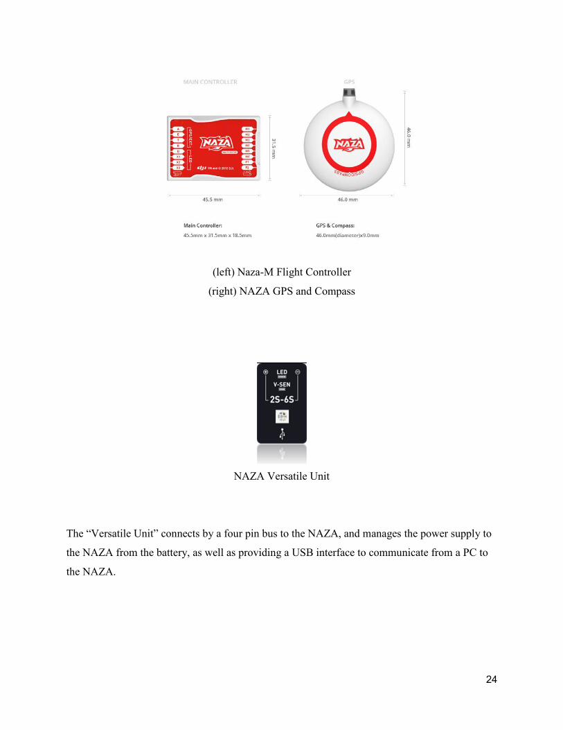
(left) Naza-M Flight Controller
(right) NAZA GPS and Compass
NAZA Versatile Unit
The “Versatile Unit” connects by a four pin bus to the NAZA, and manages the power supply to
the NAZA from the battery, as well as providing a USB interface to communicate from a PC to
the NAZA.
24
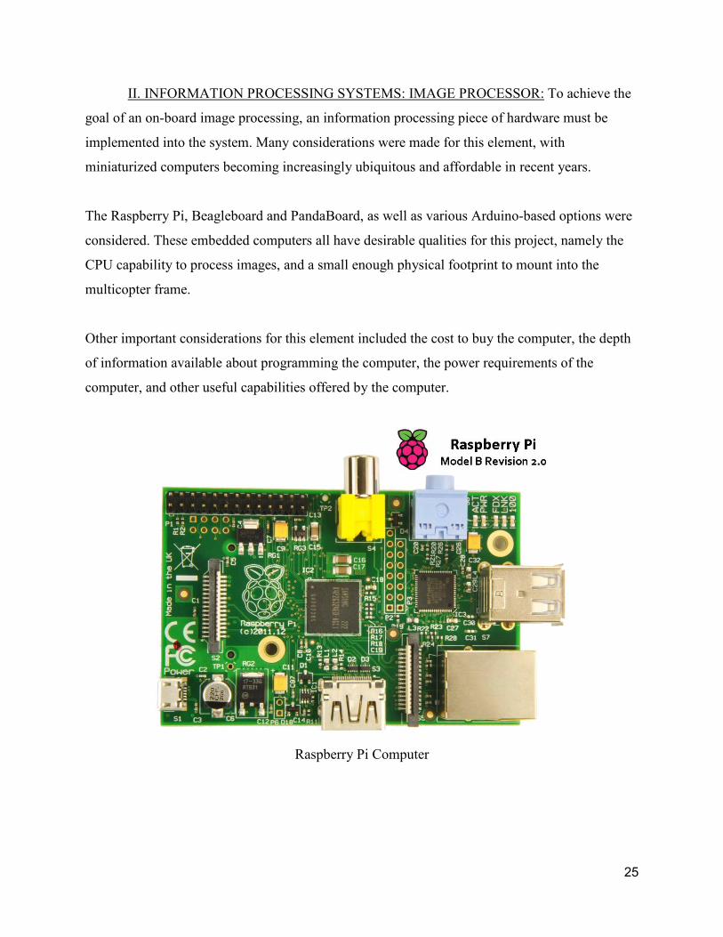
II. INFORMATION PROCESSING SYSTEMS: IMAGE PROCESSOR: To achieve the
goal of an on-board image processing, an information processing piece of hardware must be
implemented into the system. Many considerations were made for this element, with
miniaturized computers becoming increasingly ubiquitous and affordable in recent years.
The Raspberry Pi, Beagleboard and PandaBoard, as well as various Arduino-based options were
considered. These embedded computers all have desirable qualities for this project, namely the
CPU capability to process images, and a small enough physical footprint to mount into the
multicopter frame.
Other important considerations for this element included the cost to buy the computer, the depth
of information available about programming the computer, the power requirements of the
computer, and other useful capabilities offered by the computer.
Raspberry Pi Computer
25

With these considerations taken into account, the RPi (Raspberry Pi) was chosen as the image
processing computer for the UAV. At $35 the RPi is the most affordable computer of those
considered. With a 700MHz, ARM11 processor, the RPi has more than enough CPU headroom
to carry out image processing. In addition, the RPi model B features two USB ports, and can
support more USB devices using a USB hub. A wide variety of sensors and other accessories,
including WiFi and BlueTooth adapters, can communicate easily over this bus system, utilising
plug-and-play functionality.
SIGNAL SWITCHING CIRCUIT: To deliver navigational information to the NAZA FC
from the RPi, a communication channel had to be developed. The RPi has GPIO ports which can
be utilised to provide outputs that the NAZA can recognise as control signals. The four standard
flight control signals, throttle; yaw; pitch and roll, can be generated from these outputs.
Additionally, a signal to govern the pitch of the camera gimbal can be generated.
An equivalent signal for each channel is also supplied to the NAZA from the RC receiver. These
signals cannot both connect to the same input that the NAZA recognises as a control signal. In
electronic logic devices like the NAZA, ports that recognise an input signal cannot be attached to
more than one input, or the multiple input-driving devices will clash for control of the voltage at
the node of implementation.
To separate these distinct signals, an electromechanical PCB switching circuit was implemented
into the design. The switching circuit was originally designed by Senior Electronics Technician
Jonathan Brant from the UWA faculty of Electrical and Electronic Engineering.
26

The Signal Switching Circuit
made by Mr Jonathan Brant
This switching circuit was designed over 5 years ago, and due to a misallocation of some
archival data, the original schematic for the module was not available. However, the original
PCB layout file was recovered by Mr Brant. The function of this unit is to receive two different
channels of electronic signals (A and B) from separate ports (for this project the signals were
PWM), and exclusively route one signal or the other to a single channel output. This module
features eight independent instances of this switching function within the layout of the board, so
up to eight channels can be routed as outputs from up to sixteen distinct inputs. The decision of
which of the two signals is chosen for each channel is based on a PWM signal supplied to a
separate controlling input.
27
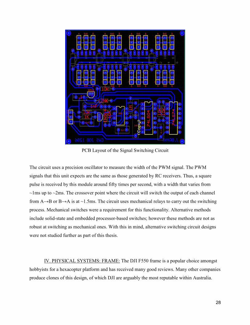
PCB Layout of the Signal Switching Circuit
The circuit uses a precision oscillator to measure the width of the PWM signal. The PWM
signals that this unit expects are the same as those generated by RC receivers. Thus, a square
pulse is received by this module around fifty times per second, with a width that varies from
~1ms up to ~2ms. The crossover point where the circuit will switch the output of each channel
IURP�$ĺ%�RU�%ĺ$�LV�DW�a���PV��7KH�FLUFXLW�XVHV�PHFKDQLFDO�UHOD\V�WR�FDUU\�RXW�WKH�VZLWFKLQJ�
process. Mechanical switches were a requirement for this functionality. Alternative methods
include solid-state and embedded processor-based switches; however these methods are not as
robust at switching as mechanical ones. With this in mind, alternative switching circuit designs
were not studied further as part of this thesis.
IV. PHYSICAL SYSTEMS: FRAME: The DJI F550 frame is a popular choice amongst
hobbyists for a hexacopter platform and has received many good reviews. Many other companies
produce clones of this design, of which DJI are arguably the most reputable within Australia.
28

This frame was purchased from PerthRC as part of the DJIF550 package that included
proprietary ESCs, rotor blades and the aforementioned NAZA-M flight controller.
DJI F550 Frame
V. PHYSICAL SYSTEMS: MOTORS: Brushless DC motors are the best choice for
generating mechanical rotation of the rotor blades. Six AXi 2217/20 brushless motors were used
for the hexacopter frame. These motors have a KV rating of 840, so the rotors should spin up to
9324 RPM when using an 11.1V, three cell LiPo battery. These motors were chosen to replace
the standard DJI brushless motors, under the advice of the PerthRC staff. The AXi motors offer
more power and efficiency than the DJI motors.
VI. PHYSICAL SYSTEMS: Electronic Speed Controllers (ESCs): The brushless motors
are powered by ESCs. The ESCs that were used in this project are 6x DJI 30A OPTO ESCs,
which are supplied as part of the DJI F550 kit.
29

DJI 30A OPTO ESCs
VII. PHYSICAL SYSTEMS: BATTERIES:
The batteries used to power the UAV are 5000mAh, 11.1V LiPo type. Two were purchased to be
able to test the platform using one battery while charging the other battery.
VIII. COMMUNICATION SYSTEMS: RC TRANSMITTER and RECEIVER: The RC
transmitter used for this project was the Futaba 14SG. This particular model became available in
2013. The advanced computer radio system was chosen over cheaper systems for several
reasons. Firstly, the company is highly reputable within the RC hobby industry. Secondly, the
system boasts 12 proportional channels and 2 switched channels of simultaneous data
transmission and reception. The proportional channels are programmed to transmit data collected
from one of many physical interfaces. These physical interfaces include the left and right control
sticks, multi positional switches and rotary knobs. The switched channels only transmit binary
data, and are assigned to two-position switches. These extra channels are essential for both
controlling the flight of the UAV, but also for activating and selecting different flight modes and
functionalities.
30
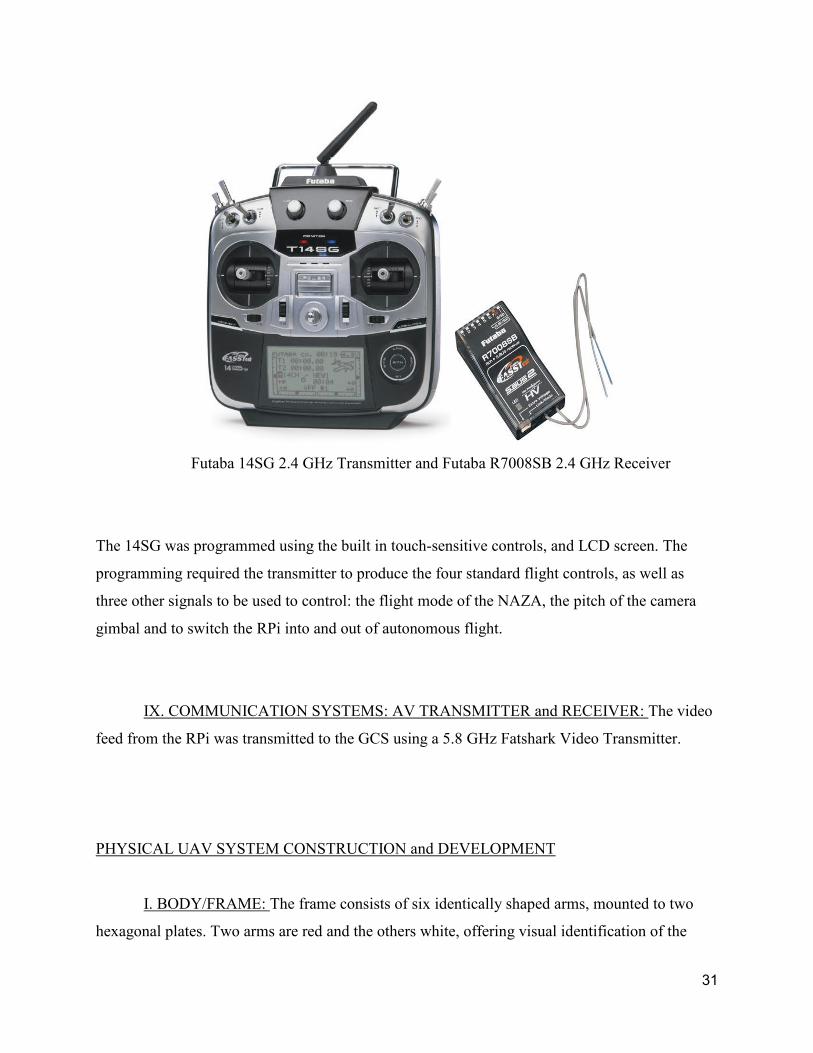
Futaba 14SG 2.4 GHz Transmitter and Futaba R7008SB 2.4 GHz Receiver
The 14SG was programmed using the built in touch-sensitive controls, and LCD screen. The
programming required the transmitter to produce the four standard flight controls, as well as
three other signals to be used to control: the flight mode of the NAZA, the pitch of the camera
gimbal and to switch the RPi into and out of autonomous flight.
IX. COMMUNICATION SYSTEMS: AV TRANSMITTER and RECEIVER: The video
feed from the RPi was transmitted to the GCS using a 5.8 GHz Fatshark Video Transmitter.
PHYSICAL UAV SYSTEM CONSTRUCTION and DEVELOPMENT
I. BODY/FRAME: The frame consists of six identically shaped arms, mounted to two
hexagonal plates. Two arms are red and the others white, offering visual identification of the
31
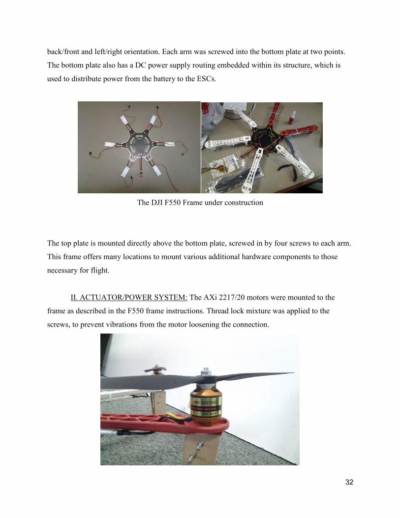
back/front and left/right orientation. Each arm was screwed into the bottom plate at two points.
The bottom plate also has a DC power supply routing embedded within its structure, which is
used to distribute power from the battery to the ESCs.
The DJI F550 Frame under construction
The top plate is mounted directly above the bottom plate, screwed in by four screws to each arm.
This frame offers many locations to mount various additional hardware components to those
necessary for flight.
II. ACTUATOR/POWER SYSTEM: The AXi 2217/20 motors were mounted to the
frame as described in the F550 frame instructions. Thread lock mixture was applied to the
screws, to prevent vibrations from the motor loosening the connection.
32

Mounted brushless motors
III. RASPBERRY PI CAMERA MODULE: This module was chosen to replace the USB
webcams that had originally been used to investigate image processing within this project. The
camera is produced especially for the Raspberry Pi computer, and is designed to accommodate
camera functionality into Raspberry Pi Projects.
IV. POWERED CAMERA GIMBAL: This device is used to stabilise the RPi camera
during flight. Initial tests were attempted without this piece of equipment, and with the RPi
camera mounted rigidly to the UAV frame. However, the change in attitude associated with
flying the UAV also affected the camera, which severely affected the cameras field of view. This
effect made tracking an object impossible while moving the UAV.
33

Scratch-Built Camera Gimbal for Raspberry Pi Camera
This gimbal, due to budgetary restrictions, was hand made from scrap parts found in the CIIPS
Robotics Lab. The camera board was attached to a piece of 3mm clear acrylic, which was
mounted to the back of a servo motor. The control horn of this rotor was mounted to a strip of
acrylic that was heat-formed into a right angle at one end. The other end is mounted to the
control horn of a second servo motor. This servo motor is mounted directly onto the DJI 550
case.
After construction, the servo connectors were plugged into the relevant NAZA outputs that
control the pitch and roll of the camera. The parameters that define the way the NAZA controls
the gimbal were programmed into the computer.
This process is carried out by trial and error, testing the resulting gimbal action against the
expected response. When the camera on the gimbal would remain in position despite changes to
the attitude of the frame, the tuning was complete.
QSTARZ GPS 818X Module
34

V. GPS: The autonomous programs that this platform is intended to carry out require
GPS location information available to the RPi. Although the NAZA FC uses a GPS device,
unfortunately this device is propriety hardware of DJI, and could not be communicated with
from the RPi. Instead, a QSTARZ GPS 818X module was used. This unit came from the CIIPS
lab and had been used in other autonomous projects before. Though not as compact, new or fast
as the GPS that the NAZA is using, the QSTARZ GPS never the less worked fine for achieving
the goals of this project.
VI. IMU: In order to measure the magnetic bearing of the UAV, an IMU, in particular
one that measures magnetic forces, such as a magnetometer, was required. The IMU used was
the XSens MTi, which can measure acceleration, angular acceleration (gyroscopic) and compass
bearing in three dimensions. Like the QSTARZ GPS, this IMU was available in the CIIPS lab
from previous robotics projects.
OVERVIEW OF COMPLETE SYSTEM:
35

The Complete System
The plot above the components that were included in the final design, as well as the interaction
between these components. Black arrows designate the flow of information through internal
electronic signals, blue arrows designate the flow of information through other physical modes,
and the red arrow is the red arrow is the flow of information from the human operator to the
controls.
SYSTEM PROGRAMMING
The RPi comes as a standalone unit without an operating system. The operating system was
loaded onto an SD card. The operating system, as well as instructions on how to setup the RPi in
general, was found at http://www.raspberrypi.org/.
36

GATHERING SENSOR DATA
The first sensor to be implemented was a USB webcam. However, when the camera module for
the RPi was released, work was focussed towards implementing this unit into the design,
replacing the USB webcam.
A USB GPS device was incorporated into the design in order to track the position of the UAV
during testing and operation.
Measuring of the compass bearing of the UAV program, was required for the RPi to sense the
rate of rotation of the UAV. The XSens IMU was implemented into the design to fulfil this
requirement.
PROCESSING SENSOR DATA
Programs were developed in C code to operate on the RPi. Using either the analog or HDMI
video outputs, code can be written directly inside the Raspbian OS. The basic word
processing program that comes with Raspbian, called Leafpad, is the easiest way to start this.
The Raspbian OS environment is slower on the RPi compared to using a modern desktop PC.
Because of this, code was usually developed on a faster PC and sent over a network connection
to the Raspberry Pi. WinSCP, a free FTP program that can connect to the Raspberry Pi from a
windows PC using the SSH protocol, was used to conduct this transfer. Compilation of the code
is carried out on the Raspberry Pi
To compile, the built-in gcc compiler was used. Each .c file needs a makefile that outlines the
requirements of the code for the compiler. Information detailing code libraries, folder locations,
as well as other .c files that may be called by the main program, is included here.
37
One online tutorial series that described the process of implementing image processing
functionality onto the RPi, recommended using CMake to compile code. For the purpose of
emulating the results of the tutorial, this program was also used.
Image processing was carried out using functions from the OpenCV library. OpenCV is an open
source, computer vision based project.
DESIGNING INTELLIGENT, TASK ORIENTATED FUNCTIONS
The desired function that was most important was image processing, and in particular case using
the information to control the movement of the UAV. The original implementation of the
program simply filtered through real time image data for a red object, as shown in the flow chart
on the following page.
38
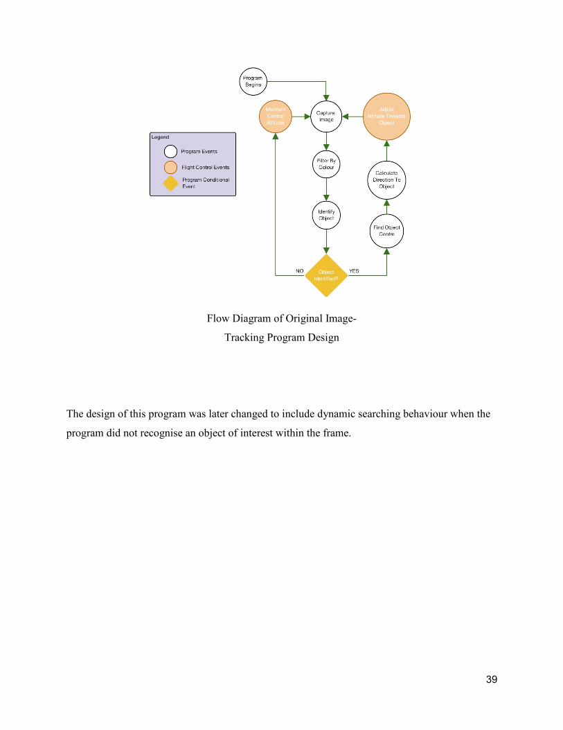
Flow Diagram of Original Image-
Tracking Program Design
The design of this program was later changed to include dynamic searching behaviour when the
program did not recognise an object of interest within the frame.
39
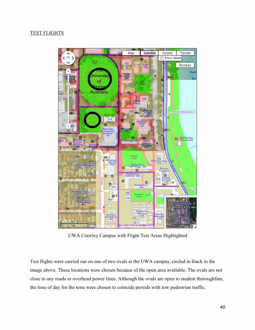
TEST FLIGHTS
UWA Crawley Campus with Flight Test Areas Highlighted
Test flights were carried out on one of two ovals at the UWA campus, circled in black in the
image above. These locations were chosen because of the open area available. The ovals are not
close to any roads or overhead power lines. Although the ovals are open to student thoroughfare,
the time of day for the tests were chosen to coincide periods with low pedestrian traffic.
40
The analog video from the RPi is transmitted to the GCS, where the desktop environment of the
RPi can be viewed on a portable monitor. By this method, the state of the program running on
the RPi could be assessed.
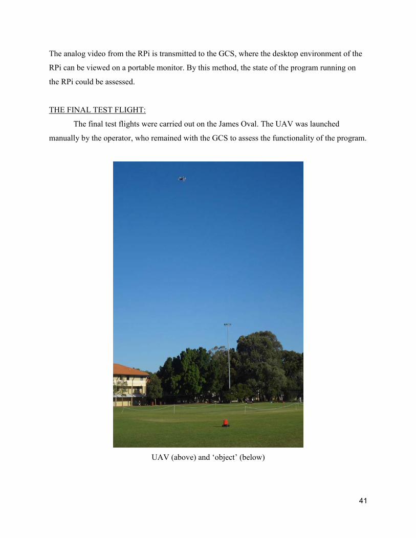
THE FINAL TEST FLIGHT:
The final test flights were carried out on the James Oval. The UAV was launched
manually by the operator, who remained with the GCS to assess the functionality of the program.
UAV (above) and ‘object’ (below)
41
A second operator was in control of toy RC truck which was driven along the ground. The RC
truck had a bright red dust bin attached above (see figure above). The UAV was flown to where
it could look straight down to see the red bin.
When the GCS showed that the RPi had indeed recognised the red bin, the UAV operator
activated the switching circuit, relinquishing control of the pitch, roll and yaw of the UAV to the
RPi.
After three seconds, the RPi begins to adjust its attitude to try and reframe the object in the
centre of its display. This successfully results in the UAV hovering steadily above the bin. The
RC truck operator then begins to drive the red bin around the oval.
The UAV continues to adjust its attitude to compensate for the movements of the red bin, in
every ground direction. The RC truck is moving at roughly 1 m/s. When the truck is quickly
driven away and leaves the frame of the RPi camera, the UAV stops where it currently is after
moving in the last direction the red lid was seen briefly.
The RC truck is left about 15m away from the point on the ground directly below the UAV. To
find the red bin again, the UAV begins to slowly rotate on the spot. After it has made a complete
circle, the RPi pitches the camera up slightly, to view a slightly larger area around itself, and
continues to rotate.
42

Flow Chart Depicting Events
Of Final Tracking Program
After 2-3 rotations, red bin is again within the frame of the RPi camera. The UAV then stops
rotating, and moves forwards towards the stationary red bin. As the UAV moves, the bin moves
to a lower in the frame of view of the camera, and the RPi adjusts the pitch of the camera gimbal
down again to compensate. This continues until the camera is pitched directly down, as it was to
begin. At this point, the program continues trying to maintain the red lid in the frame buy
adjusting the attitude, as it began the test.
The same process is repeated three more times over the week, and recorded by the Supervisor on
camera. The platform and program are now considered safe and robust for further
demonstrations.
43

VII. CONCLUSIONS
The UAV developed by final year students in 2013 underwent many tests throughout the year.
Initial tests were carried out simply to gain an understanding of the equipment being used. The
final tests carried out in the week before this thesis was submitted demonstrate the achievement
of the goals that were set out at the beginning of the year. The platform was researched, the parts
were procured, the system was successfully constructed and programmed to carry out the goal of
tracking ground objects, using on-board image processing. This goal has however, only been
achieved so far in a superficial capacity. Due to the time spent troubleshooting the final program,
currently no strong numerical results have been put together to support the success of the
platform. Nevertheless, to see the UAV during a live demonstration is a powerful testimony to
the efficacy of the system that has been developed.
The UAV was chosen to be large and powerful enough to carry a RPi with the additional
hardware accessories that provide the necessary information to achieve autonomy. Though these
components do not individually constitute a large weight relative to the UAV, the combination of
components, as well as additional cables contribute as a heavy payload.
The power loss of the UAV is proportional to the payload it must lift with the rotors.
Additionally, the payload is largely composed of active powered components. These devices also
draw current and power from the UAV during normal operation.
The combination of these effects is understood to be the main reason for the diminished duration
of flight times observed, as the project continued and more weight and power-consuming devices
were incorporated into the system.
This platform in its current state serves as a fantastic demonstration tool to showcase UAV
robotics capabilities as well as the quality of work being produced at UWA. In the weeks that
follow the submission of this thesis, three separate demonstrations of the UAV have been
arranged: an excursion to demonstrate at a Primary School; and two incursions at UWA from a
delegation of Malaysian visitors and from a High School.
44

LIMITATIONS AND ADVANTAGES
This work shows many promising results, however there exist distinct limitations to what can be
drawn from the results.
I. TESTING LIMITATIONS: The UAV was tested on the UWA campus in two
locations: the James Oval, and the nearby oval between the Civil Engineering and the molecular
and chemical sciences buildings. Due to CASA restrictions governing the operations of UAVs,
the system was never flown above 400ft. Since this is about ~40 stories in building dimensions,
and no UWA buildings are this tall, the altitude restriction was achieved by keeping the UAV
below the rooftop of the tallest nearby building. Typical flight altitudes were 10-30m from the
ground. Outside of this volume of space, the system has not been tested.
II. PERFORMANCE LIMITATIONS: The added weight and power consumption
associated with the modules that are necessary to carry out autonomy limit the flight times to less
than 10 minutes. The platform in the current state cannot be tested for longer periods than this
continuously. As such, no conclusion can be made about the quality of the program after longer
periods of operation.
III. PROGRAM LIMITATIONS: The autonomous program is currently only calibrated
to identify a red object based on a fixed threshold of the HSV pixel values of the object (a red
dust bin) that were measured. The testing area is above grass which is bright green, which is not
identified by the program. This program is essentially limited to only finding this colour, and
only when no other similarly coloured objects are also in the camera frame.
APPLICATION OF RESULTS
The results from this thesis have a variety of applications. The existing system could be
reprogrammed to carry out a variety of different functions in various scenarios, from educational
demonstrations to industrial applications. Some particular examples are described below:
45
Simple track and follow: Using the RPi camera, the UAV can identify and follow a target
based on colour recognition. The UAV could be set up to follow a person, ground vehicle or
another UAV.
An operator could ride in a car that the UAV is programmed to lock onto. The operator can be
driven through open, outdoor terrain, with the UAV following the car. Additional gimbal-
actuated cameras can be mounted to the UAV, which capture video based on the desired
viewpoint of the operator. In other words, the UAV could automatically follow a moving GCS by
this method, removing some possible human error from the operation.
Complex Tracking and Identification: Theoretically, the UAV could carry out image
processing functions in environments outside of the LOS of the operator. The UAV could follow
a strictly described route, governed by on-board GPS. As the UAV travels, it can scan the ground
below searching for objects that can be filtered out of the image feed. When an object is
identified, a number of different actions could be programmed to take place, such as follow, or
relay positional information to the operator.
This functionality may be utilised in the process of search and rescue, where one or perhaps
many drones can be deployed to scan for people who may be lost or stranded in sparse or
dangerous environments. The camera used for image processing in this thesis could be replaced
with a more powerful, perhaps multispectral or thermal camera, which can easily identify warm
human bodies. After capturing the image data and porting the data to the RPi or other
microcomputer, the same functionalities achieved in this project could be utilised to identify,
lock onto and even track the target, while relaying relatively simple positional data back to a
GCS using low frequency telemetry channels.
The same implementation could be carried over into shoreline shark patrolling services.
Operators could deploy multiple UAV platforms to monitor popular beaches for the presence of
sharks, using digital cameras designed to be able to see the large fish swimming underwater.
46
The on-board image processing investigated in this thesis, over existing off-board image
processing techniques, is particularly advantageous in applications of this type. The autonomous
image processing functionality of the UAV is not adversely affected by interference to the video
transmission over radio. Also, the autonomous flight control is highly resilient to interference
across to the RC transmission. These resistances contrast to the complications associated with
carrying out a coordinated
Further Recommendations for the UWA Hexacopter Project:
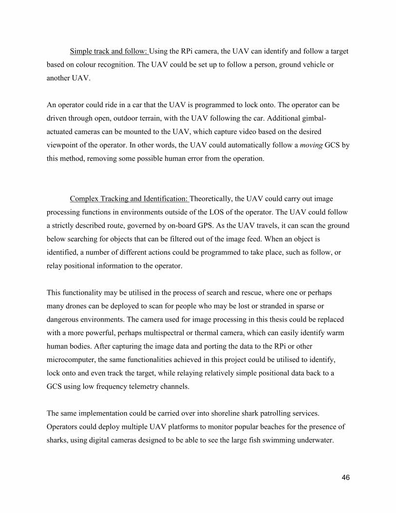
Design of an improved FPV receiver is recommended. The existing FPV receiver system
is very mobile, but cannot be focussed towards the source of the FPV transmission. Due to the
use of a stationary GCS for test flying the UAV, mobility of the receiver system is not essential.
David Windestål’s Homemade Video Receiver
47
Development of a customised antenna with a reflective dish to receive FPV is recommended.
The image above shows the system designed by David Windestål. The instructions to build this
system are available for free at the FliteTest website where David works. The helical antenna in
front of the orange dish can be directed towards the source of the FPV transmission. The dish
acts as a reflector, helping focus the EM radio signal into the antenna and improving the quality
of the reception.
This particular system was built to operate in the 1200 MHz frequency band, and would be
incompatible with the UWA project, which transmits FPV data in the 5.8 GHz frequency band.
However, by replacing the 1200 MHz receiver and antenna with a 5.8 GHz equivalent, the new
receiver system would be able to receive data from the existing transmitter.
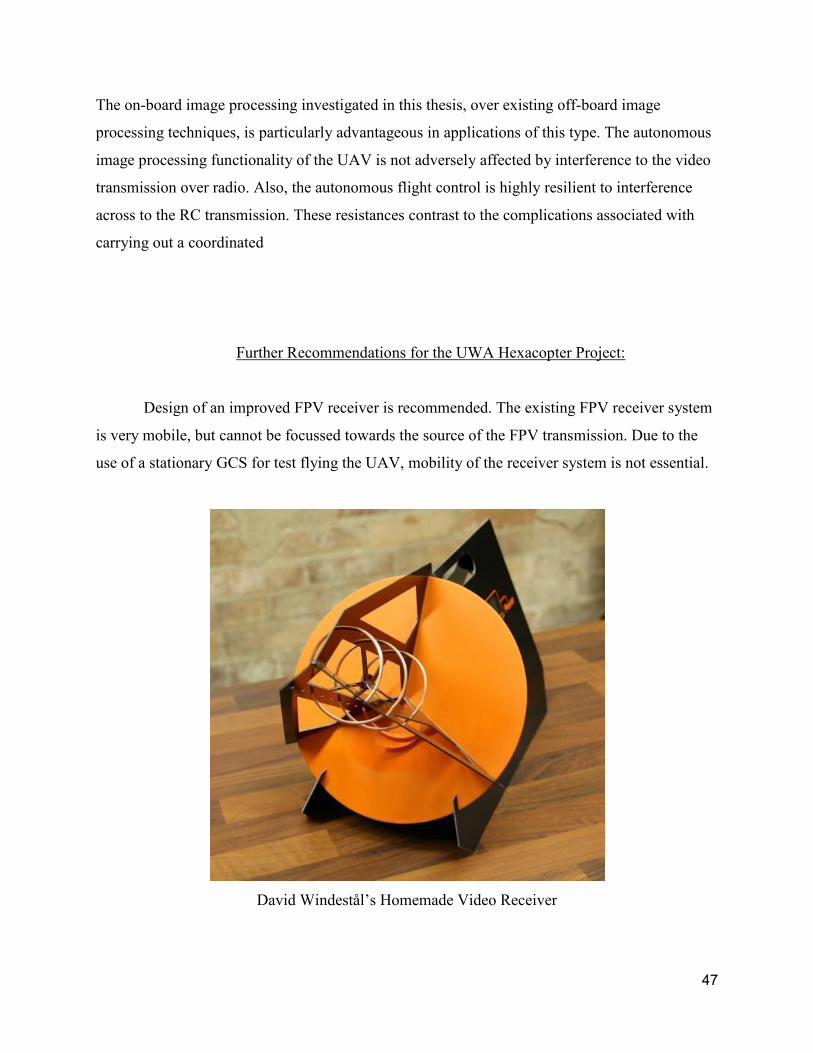
5.8 GHz 5 Turn Helical Antenna
The figure above shows an equivalent 5.8 GHz antenna that also features a reflector dish. This
unit is available to buy for $34US from the ReadymadeRC website.
Telemetry capabilities are recommended to be investigated, to deliver relevant flight control
information back to the GCS such as the altitude and GPS position of the UAV.
48
Small, USB Multimeters are recommended to accurately measure and record power and voltage
consumption during the flight process.
Incorporate multiple cameras to investigate stereo vision-based image processing functionalities.
The stereoscopic effect this setup offers could be used to develop grayscale depth images for
positional awareness around the UAV.
49

REFERENCES
1. Gonzalez, I., et al. Real-time altitude robust controller for a Quad-rotor aircraft using Sliding-
mode control technique. in Unmanned Aircraft Systems (ICUAS), 2013 International Conference
on. 2013.
2. Jiang, J., et al. Control platform design and experiment of a quadrotor. in Control Conference
(CCC), 2013 32nd Chinese. 2013.
3. Mitchell, G., The Raspberry Pi single-board computer will revolutionise computer science
teaching [For & Against]. Engineering & Technology, 2012. 7(3): p. 26-26.
4. Berezny, N., et al. Accessible aerial autonomy. in Technologies for Practical Robot Applications
(TePRA), 2012 IEEE International Conference on. 2012.
5. Sarik, J. and I. Kymissis. Lab kits using the Arduino prototyping platform. in Frontiers in
Education Conference (FIE), 2010 IEEE. 2010.
6. Reinhardt, K.C., et al. Solar-powered unmanned aerial vehicles. in Energy Conversion
Engineering Conference, 1996. IECEC 96., Proceedings of the 31st Intersociety. 1996.
7. Uragun, B. Energy Efficiency for Unmanned Aerial Vehicles. in Machine Learning and
Applications and Workshops (ICMLA), 2011 10th International Conference on. 2011.
8. Uragun, B. Energy efficiency in Nano Aerial Vehicles. in Aerospace Conference, 2012 IEEE.
2012.
9. Buchmann, I., Whats The Best Battery? 2012.
10. Edwards, C., Not-so-humble raspberry pi gets big ideas. Engineering & Technology, 2013. 8(3):
p. 30-33.
11. Krajnik, T., et al. A simple visual navigation system for an UAV. in Systems, Signals and Devices
(SSD), 2012 9th International Multi-Conference on. 2012.
12. Leishman, R., et al. Relative navigation and control of a hexacopter. in Robotics and Automation
(ICRA), 2012 IEEE International Conference on. 2012.
13. Guowei, C., et al., Modeling and Control of the Yaw Channel of a UAV Helicopter. Industrial
Electronics, IEEE Transactions on, 2008. 55(9): p. 3426-3434.
14. Al-Jarrah, M.A., et al. Autonomous aerial vehicles, guidance, control and signal processing
platform. in Systems, Signals and Devices (SSD), 2011 8th International Multi-Conference on.
2011.
50
15. Cheng, H., et al. Autonomous takeoff, tracking and landing of a UAV on a moving UGV using
onboard monocular vision. in Control Conference (CCC), 2013 32nd Chinese. 2013.
16. Daewon, L., T. Ryan, and H.J. Kim. Autonomous landing of a VTOL UAV on a moving platform
using image-based visual servoing. in Robotics and Automation (ICRA), 2012 IEEE International
Conference on. 2012.
17. Mortimer, G., German multicopter makes first manned flight. sUAS News 2011.
18. Baranek, R. and F. Solc. Modelling and control of a hexa-copter. in Carpathian Control
Conference (ICCC), 2012 13th International. 2012.
19. Oosedo, A., et al. Design and simulation of a quad rotor tail-sitter unmanned aerial vehicle. in
System Integration (SII), 2010 IEEE/SICE International Symposium on. 2010.
20. Gaponov, I. and A. Razinkova. Quadcopter design and implementation as a multidisciplinary
engineering course. in Teaching, Assessment and Learning for Engineering (TALE), 2012 IEEE
International Conference on. 2012.
21. Sebesta, K. and N. Boizot, A Real-Time Adaptive High-gain EKF, Applied to a Quadcopter
Inertial Navigation System. Industrial Electronics, IEEE Transactions on, 2013. PP(99): p. 1-1.
22. Morar, I. and I. Nascu. Model simplification of an unmanned aerial vehicle. in Automation
Quality and Testing Robotics (AQTR), 2012 IEEE International Conference on. 2012.
23. Achtelik, M.C., et al. Design of a flexible high performance quadcopter platform breaking the
MAV endurance record with laser power beaming. in Intelligent Robots and Systems (IROS),
2011 IEEE/RSJ International Conference on. 2011.
24. Achtelik, M., et al. Visual tracking and control of a quadcopter using a stereo camera system and
inertial sensors. in Mechatronics and Automation, 2009. ICMA 2009. International Conference
on. 2009.
25. Jie-Tong, Z. and T. Yu-Chiung. Visual Track System Applied in Quadrotor Aerial Robot. in
Digital Manufacturing and Automation (ICDMA), 2012 Third International Conference on. 2012.
51

APPENDICES
CASA UAV rules www.defense.gov/specials/uav2002/
DJI www.dji.com/
UWA EYEbots robotics.ee.uwa.edu.au/eyebot/
FliteTest www.flitetest.com/
WinSCP winscp.net/
OpenCV opencv.org/
Raspberry Pi www.raspberrypi.org/
Pierre Raufast’s RPi website thinkrpi.wordpress.com/
David Windestål’s Video Receiver
flitetest.com/articles/The_Overkill_FPV_Ground_Station
Helical Antenna:
www.readymaderc.com/store/index.php?main_page=product_info&products_id=1090
52