development and application of ptfe compound …development and application of ptfe compound...
TRANSCRIPT

Development and Application of PTFE Compound Bearings
Mr. Seiji YamajoKobelco Eagle Marine Engineering Co., Ltd.
Mr. Fumitaka KikkawaMikasa Corporation

Fig.1 Structure of three-layer bearing

Table 1 Characteristics of three-layer bearing

Fig. 2 Manufacturing equipment of PTFE bearing

Fig. 3 Construction of PTFE bearing

Table 2 Comparison between rubber bearing and PTFE bearing

Fig. 4 Friction characteristics

Table 3 Test condition of friction coefficient test
Item Condition Material 70-30 Copper-Nickel
Shaft Sleeve Diameter 140 mm (5½ inches)
Material PTFE Compound Bearing
+0.5 Diameter 140 +0.6
mm Bearing
Length 140mm
Shaft Revolution 6~490 r.p.m. (0.04~3.5 m/s)

0
0.05
0.1
0.15
0.2
0.25
0.3
0 0.5 1 1.5 2 2.5 3 3.5 4
Speed (m/s)
Fric
tion
Coe
ffici
ents
FFB
MIL SPEC
break away�0.1498
build up�0.1799
Fig. 5 Dynamic and static friction coefficients

Table 4 Heat resistance

Fig. 6 Swelling in seawater

Table 5 Young’s modulus of bearing

Fig. 7 Bearing pressure on bracket bearing

Fig. 8 Durability in dry condition

Fig. 9 No water supply test equipment

Fig. 10 Temperature of bearing

Fig. 11 Abrasion test equipment (Shaft dia. –
200mm)

Fig. 12 Water supply line of test equipment

Table 6 Test condition (1)

Fig. 13 Wear after 1000 hours
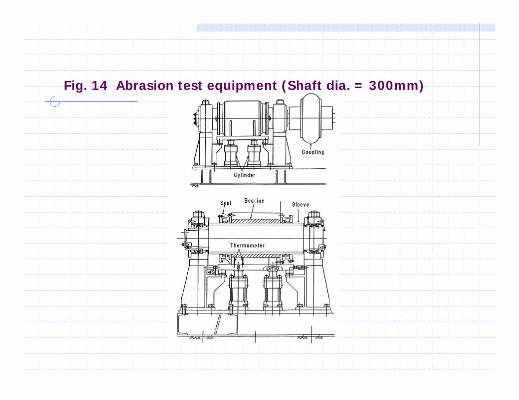
Fig. 14 Abrasion test equipment (Shaft dia. = 300mm)

Table 7 Test condition (2)

Table 8 Load condition

Fig. 15 Wear test for four months

Table 9 ABS Design Assessment
Item Condition
Lubrication Water Lubricated Stern Tube Bearing
Shaft Diameter (D) 40mm (1.6 inch) ~ 1,000mm (40 inch)
Bearing Length (L) L ≥ 2 x D
Load on Bearing
Average Pressure Less than 6 kgf/cm²
Max. Local Pressure Less than 20 kgf/cm²

Fig. 16 Change of clearance on a Destroyer

Fig. 17 Change of clearance on a Guided Missile
Destroyer
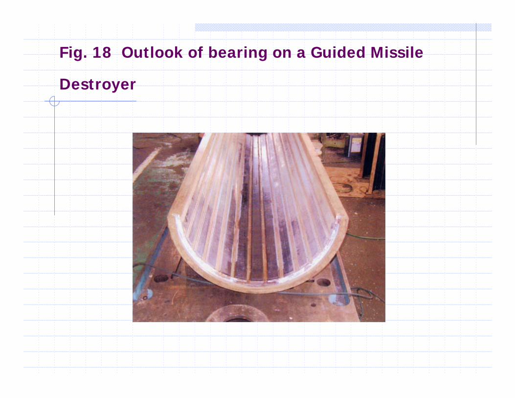
Fig. 18 Outlook of bearing on a Guided Missile
Destroyer

Fig. 19 Structure of cruising ferry

Fig. 20 Clearance of bearing at position 1

Table 10 Reference list of PTFE compound
bearing
No. Type of Vessel Delivery Bearing Size Q'tyStrut ; Ø305 x 1180L 2 1 Fishing Boat May-03 S/T ; Ø305 x 1180L 2 Strut ; Ø198 x 600L 2 2 Fishing Boat Jun-03 S/T ; Ø198 x 600L 2 Strut ; Ø241 x 900L 2 3 Fishing Boat Oct-03 S/T ; Ø241 x 900L 2 Strut ; Ø165 x 570L 2 4 Fishing Boat Feb-04 S/T ; Ø165 x 570L 2 Strut ; Ø368 x 1300L 2 S/T Aft ; Ø368 x 700L 2 5 Ocean Tug Boat Apr-04 S/T Fwd ; Ø367 x 700L 2
6 Supply Boat May-04 Strut ; Ø203 x 700L 1