development and characterization of electrospun …
TRANSCRIPT
DEVELOPMENT AND CHARACTERIZATION OF ELECTROSPUN POLYMER SCAFFOLDS FOR 3D
CELL CULTURE MODEL TO MIMIC HUMAN INTESTINE SYSTEM
A Thesis Submitted to The Graduate School of Engineering and Science of
Technology In Partial Fulfillment of the Requirements for the Degree of
MASTER OF SCIENCE
In Bioengineering
by
December 2020

ii
ACKNOWLEDGEMENTS
Initially, I would like to thank to the people who contributed to my thesis in
different ways. First, I would like to express my deepest regards and thanks to my
supervisor Assoc. Prof. Dr. Ahu ARSLAN YILDIZ for her patient, encouraging, and
understanding guidance and extensive knowledge throughout my graduate studies and
thesis writing.
I would like to express my special thanks to my co-
for their attention, suggestions and advice. Also, I am thankful to Assoc. Prof.
D
support.
I have very special thanks to my friends and co-
also grateful to my other co-workers for their help and kindness during my thesis.
Additionally, I would li
for their encouragement on my academic career. Specifically, I have very special thanks
to dea
experiences and helps to me. Thank you for his precious information he provided to me.
their endless love, infinite believe, and support to me throughout my life. I would like to
thank to my dear sister and b
endless love and support.
iii
ABSTRACT
DEVELOPMENT AND CHARACTERIZATION OF ELECTROSPUN
POLYMER SCAFFOLDS FOR 3D CELL CULTURE MODEL TO
MIMIC HUMAN INTESTINE SYSTEM
Intestinal tissue engineering is a subfield of tissue engineering, which utilizes
biomaterials to mimic the extracellular matrix (ECM) for tissue regeneration, repairment,
simulating intestine function in 3D models. It combines scaffolds, which are obtained
from natural, semisynthetic or synthetic polymer by using different fabrication methods,
with various intestinal cells. In this thesis, polycarbonate (PC), polycaprolactone (PCL)
and Polyvinylidene fluoride (PVDF), which are synthetic polymers, were used for
fabrication of scaffolds by electrospinning to obtain an alternative material against
commercial Transwell supports. Thus, electrospun PC, PCL and PVDF scaffold
containing a 12-well Transwell insert was designed by sandwiching between two PMMA
circles. To observe cellular behavior on scaffolds Caco-2 cells, which are most used
human colorectal cancer cells in the intestinal tissue engineering system, were cultured
on electrospun PC, PCL and PVDF scaffolds. According to cell viability analysis, toxic
effect was not observed at the end of 21 days culturing period. Additionally, DAPI/Actin
and collagen staining was performed for 21-days and results proved that intra/intercellular
components and proteins were expressed successfully. As known in literature, Caco-2
cells make a tight junction that is formed by paracellular interactions after 3-4 weeks
culturing. To analyze tight junction integrity, phenol red transport and transepithelial
resistance were measured. The permeability of phenol red for PCL scaffold exhibited a
significant decrease from 50% to 12% after 21 days on the contrary of PC and PVDF. In
parallel, TEER measurements supported the phenol red transport assay because in PCL
results showed that on the 7th day TEER was measured 468 2 in average and 21st day
measurement was calculated approximately 1133 m2.
iv
KARAKTERIZASYONU
ak dok modellerini
etmek tezde,
12 kuyulu Traswell, iki PMMA dairesi
ektal
- r PC, PCL ve PVDF iskelelerinde
Caco- eleri 3-
ve tight junction gibi
ve transepitelyal elektriksel C ve PVDF'nin aksine 21 g
8
3
v
TABLE OF CONTENTS
LIST OF FIGURES ....................................................................................................... viii
LIST OF TABLES........................................................................................................... xi
CHAPTER 1. INTRODUCTION ..................................................................................... 1
1.1. Aim of Thesis.......................................................................................... 1
1.2. Tissue Engineering ................................................................................. 1
1.3. Intestinal Tissue Engineering .................................................................. 3
1.3.1. Anatomy and Physiology of Human Intestines ................................ 4
1.3.2. Microstructure of Intestine ................................................................ 5
1.3.3. Extracellular Matrix Components of Intestine .................................. 7
1.3.4. 2D Cell Culture Model for Intestinal Tissue Engineering ................ 9
1.3.5. 3D Cell Culture Models for Intestinal Tissue Engineering ........... 10
1.3.5.1.Co-culture ................................................................................ 15
1.3.5.2.Microfabrication ...................................................................... 16
CHAPTER 2. MATERIALS AND METHODS ............................................................ 18
2.1. Materials ............................................................................................... 18
2.2 Methods ................................................................................................. 19
2.2.1. Fabrication of PCL, PVDF, and PC Scaffolds ................................ 19
2.2.2. Characterization Tests ..................................................................... 19
2.2.2.1. Scanning Electron Microscopy (SEM) Analysis ................. 19
2.2.2.2 Contact Angle ......................................................................... 20
2.2.2.3. Protein Adsorption ................................................................ 20
2.2.3. Microdevice Fabrication ................................................................ 21
2.2.4. In vitro Cell Culture Studies .......................................................... 22
2.2.4.1. Cell Seeding on PCL, PVDF, and PC Scaffolds .................. 22
vi
2.2.4.2. Cell Proliferation and Viability on PCL, PVDF, and PC
Scaffolds ............................................................................... 23
2.2.4.3. DAPI/F-Actin/Collagen I Staining of Caco-2 cells on PC,
PCL and PVDF Scaffolds .................................................... 24
2.2.4.5. Cell Seeding on PCL, PVDF, and PC Membrane
Containing Transwell Inserts .............................................. 25
2.2.4.6. TEER Measurement of Caco-2 cell line seeded PCL,
PVDF, and PC Membrane Containing Transwell
.Inserts ............................................................................. 25
2.2.4.7. Phenol Red Transport ........................................................... 25
CHAPTER 3. RESULT AND DISCUSSION ................................................................ 27
3.1. Fabrication of PC, PCL and PVDF Scaffolds ....................................... 27
3.2. Characterization of PCL, PVDF and PC Scaffolds .............................. 32
3.2.1 Porosity of PCL, PVDF, and PC Scaffolds ..................................... 35
3.2.2. Contact Angle of PCL, PVDF, and PC Scaffolds ........................... 38
3.2.3. Protein Adsorption of PCL, PVDF, and PC Scaffolds ................... 40
3.2.4. Hydrolytic and Enzymatic Degradation of PC, PCL, and PVDF
Scaffolds ......................................................................................... 45
3.3. In vitro 3D Cell Culture Studies ........................................................... 48
3.3.1. In vitro Proliferation Analysis on PC, PCL, and PVDF Scaffolds . 48
3.3.2. Cell Viability Assay on PC, PCL, and PVDF Scaffolds ................ 50
3.3.3. DAPI/Actin and Collagen Staining of Caco-2 cells on electrospun
PC, PCL and PVDF Scaffolds for 21 days ..................................... 56
3.3.4. Designation of Microdevice and Cell Seeding on Microfabricated
Transwell Insert .............................................................................. 60
3.3.5. TEER Measurement of Caco-2 cell line seeded PC, PCL and
PVDF Scaffolds Containing Transwell Inserts ............................... 63
3.3.6. Phenol Red Transport of PC, PCL and PVDF Scaffolds
...Containing Transwell Inserts ........................................................... 64

vii
CHAPTER 4. CONCLUSION ....................................................................................... 68
REFERENCES ............................................................................................................... 69
LIST OF FIGURES
Figure Page Figure 1. 1 The structure of villus in the human small intestine ...................................... 5
Figure 1. 2 Various cell types in villus microstructure ..................................................... 7
Figure 1. 3 Schematic diagram of major classes of ECM components in intestine ......... 8
Figure 1. 4 Schematic representation of collagen based intestinal epithelial cell
..culture system. .............................................................................................. 12
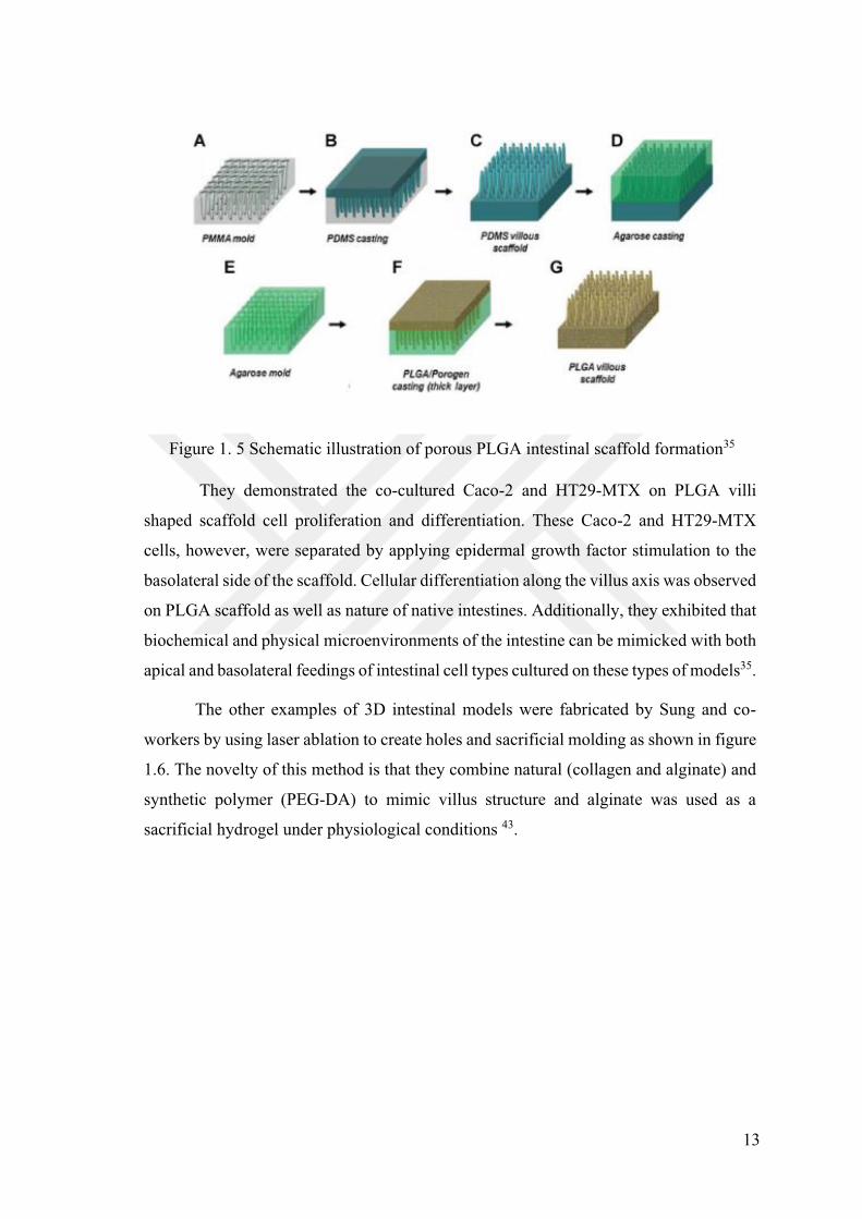
Figure 1. 5 Schematic illustration of porous PLGA intestinal scaffold formation ......... 13
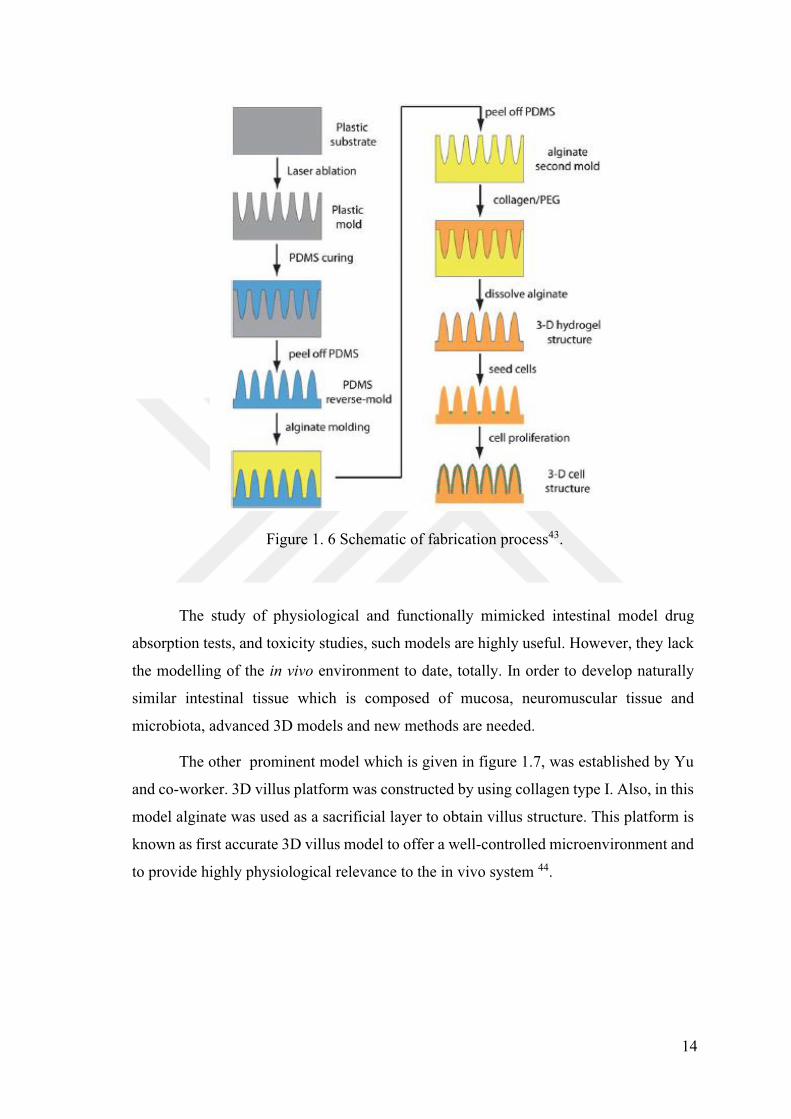
Figure 1. 6 Schematic of fabrication process. ................................................................. 14
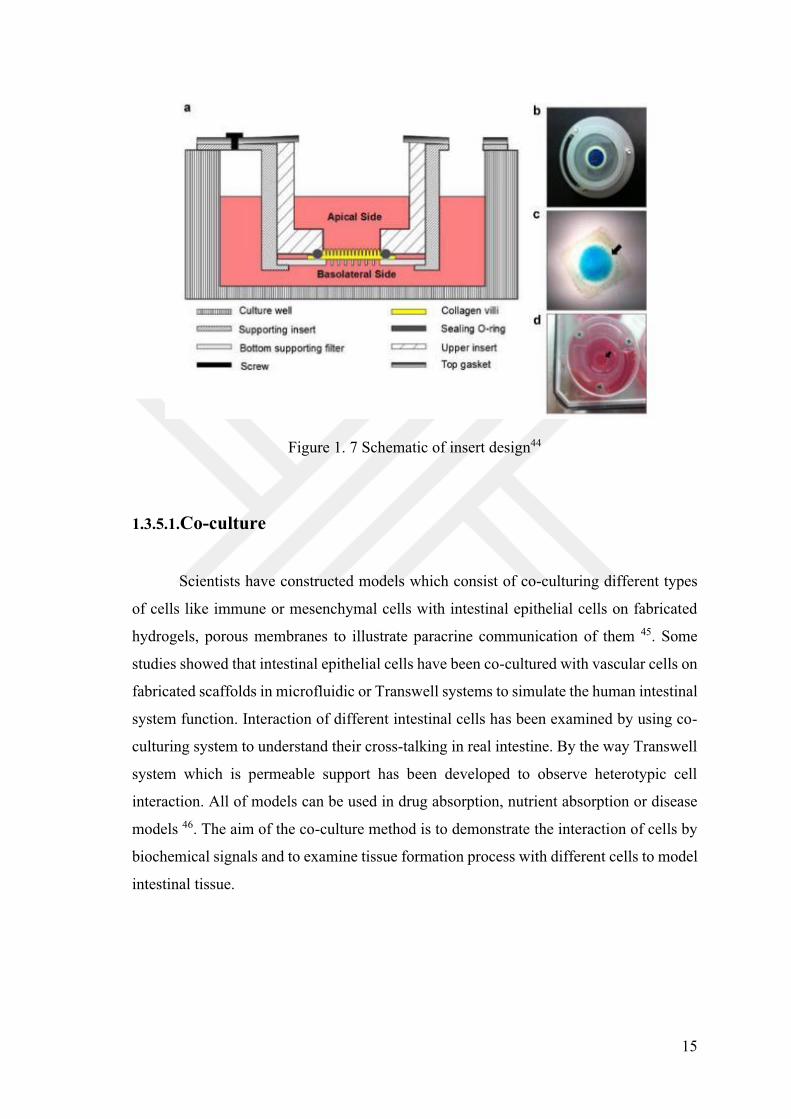
Figure 1. 7 Schematic of insert design ............................................................................ 15
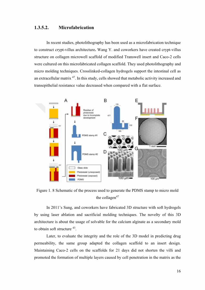
Figure 1. 8 Schematic of the process used to generate the PDMS stamp to micro mold
..the collagen ................................................................................................... 16
Figure 2. 1 Microdevice design steps 22
Figure 3. 1 SEM images of electrospun 12%wt PCL scaffolds dissolved in acetone and
..electrospun at different flow rates; 5ml/h (A, C and E) 8 ml/h (B, D, and F)
.. .................................. 28
Figure 3. 2 SEM images of electrospun 15% (A, C and E) and 18.5% (B, D and F)
..
..top to bottom) ................................................................................................ 29
Figure 3. 3 SEM images of electrospun 10 % (A, C, and E) and 15% (B, D, and F)
..PC scaffol
..from top to bottom) ....................................................................................... 30
Figure 3. 4 SEM images of electrospun 30% PVDF scaffolds dissolved in DMF:
..Acetone (4:1) at different scale 40
.. ........................................................................................................ 31
Figure 3. 5 Solubilizing adsorbed BSA on PC, PCL and PVDF with 5% SDS ............ 43
Figure 3. 6 Solubilizing adsorbed BSA on PC with 5% Tween 20 and Triton X-100
...solution. ........................................................................................................ 43
ix
Figure Page
Figure 3. 7 Solubilizing adsorbed BSA on PCL with 5% Tween 20 and Triton X-100
..solution. ......................................................................................................... 44
Figure 3. 8 Weight loss (%) graph for in vitro biodegradation analysis of electrospun
..PC in 15-week incubation period .................................................................. 46
Figure 3. 9 Weight loss (%) graph for in vitro biodegradation analysis of electrospun
..PCL in 15-week incubation period ............................................................... 47
Figure 3. 10 Weight loss (%) graph for in vitro biodegradation analysis of electrospun
.PVDF in 15-week incubation period ......................................................... 48
Figure 3. 11 Cell proliferation profiles of Caco-2 on electrospun PC, PCL and PVDF
scaffolds for 1, 2, 3, 4, 5, 6- and 7-day cell culture period, evaluated by
..................................... 49
Figure 3. 12 Fluorescence microscope images of live/ dead assay on electrospun PC
scaffolds with scaffold free control group for 21 days cell culture periods
.................................................................................................................... 51
Figure 3. 13 Cell counting Analysis of Caco-2 cells on electrospun PC scaffolds for 21
days by using the ImageJ plugin Cell Counter.
****p<0.0001). ........................................................................................... 52
Figure 3. 14 Fluorescence microscope images of live/ dead assay on electrospun PCL
scaffolds with scaffold free control group for 21 days cell culture periods
... . 53
Figure 3. 15 Cell counting Analysis of Caco-2 cells on electrospun PCL scaffolds for
21
** p<0.01, ****p<0.0001). ......................................................................... 54
Figure 3. 16 Fluorescence microscope images of live/ dead assay on electrospun PVDF
.scaffolds with scaffold free control group for 21 days cell culture periods
. epresents live cells; red represents dead cells.
. ................................................................................................................... 55
Figure 3. 17 Cell counting Analysis of Caco-2 cells on electrospun PVDF scaffolds
for ,
****p<0.0001). ........................................................................................... 56
x
Figure Page Figure 3. 18 DAPI nuclear staining (blue), Phalloidin labelled F-actin (red) and
Collagen Type I (green) fluorescent image of immunoassayed cellular
components (merged) for Caco-2 cells on control groups for 21 days.
....................................................................................... 57
Figure 3. 19 DAPI nuclear staining (blue), Phalloidin labelled F-actin (red) and
Collagen Type I (green) fluorescent image of immunoassayed cellular
components (merged) for Caco-2 cells on electrospun PC scaffolds for 21
............................................................................. 58
Figure 3. 20 DAPI nuclear staining (blue), Phalloidin labelled F-actin (red) and
Collagen Type I (green) fluorescent image of immunoassayed cellular
components (merged) for Caco-2 cells on electrospun PCL scaffolds for
........................................................................ 59
Figure 3. 21 DAPI nuclear staining (blue), Phalloidin labelled F-actin (red) and
Collagen Type I (green) fluorescent image of immunoassayed cellular
components (merged) for Caco-2 cells on electrospun PVDF scaffolds for
21 d ........................................................................ 60
Figure 3. 22 Designation of Transwell Insert by using electrospun PC, PCL and PVDF
scaffolds step by step. ................................................................................. 61
Figure 3. 23(Cont.) .......................................................................................................... 62
Figure 3. 24 (Cont) .......................................................................................................... 62
Figure 3. 25. Caco-2 cell seeding on designed PC, PCL and PVDF membrane
.Transwell insert. ......................................................................................... 62
Figure 3. 26 Trans-epithelial electrical resistance of Caco-2 cultured on 12-well
-well
insert. *** p<0.001, ****p<0.0001). ........................... 64
Figure 3. 27 % Phenol red transport measurements across the designed cell free PC,
PCL and PVDF scaffold containing Transwell insert to determine leakage
for 24 hours exposure time. ........................................................................ 65
Figure 3. 28 % Phenol red transport measurements across the Caco-2 cultured on 12-
and electrospun PCL scaffolds cell culture 12-
well insert to determine barrier integrity for 24 hours exposure time. ....... 67

LIST OF TABLES
Table Page
Table 2.1 Bovine serum albumin (BSA) standards preparation ..................................... 20
Table 3. 1 Contact angle of PVDF, PCL and PC scaffolds. ........................................... 39
Table 3. 2 TEER measurements of cell free transwell inserts ........................................ 63
1
CHAPTER 1
INTRODUCTION
1.1.Aim of Thesis
Polycarbonate and polyester (PET) membrane Transwell which are commonly used
in co-culturing to imitate functional and cell microenvironment in more natural manner
in intestinal tissue engineering are expensive so that the initial aim of thesis is to fabricate
cost-effective membrane to model barrier function as an alternative to commercial
Transwell. To provide biochemical and topographical support, nanofiber polycarbonate
(PC), polycaprolactone (PCL), and polyvinylidene fluoride (PVDF) scaffolds are
fabricated by simple electrospinning technique. Then, scaffold morphology,
hydrophobicity/hydrophilicity, protein adsorption and degradation time both enzymatic
and hydrolytic are characterized. Herein, the goal of the thesis is an integration of
fabricated scaffolds on a custom-made 12 well insert wall to promote barrier function of
the intestine. To confirm the functionality of designing system, Caco-2 cells are cultured
on PC, PCL and PVDF scaffolds for 21 days to measure TEER and permeability.
1.2.Tissue Engineering
Tissue engineering is an interdisciplinary field which combines engineering and
biological knowledge to develop, create and repair tissue and organs by using cells,
biomaterials and biologically active molecules as main components 1, 2. Biomaterials
(e.g. Natural, synthetic or semisynthetic polymers), cells (e.g. Epithelial, endothelial or
stem cells), biochemical (e.g. Growth factor), and physical signals are utilized as the
main components in tissue engineering 1.
Extracellular matrix (ECM) which known as natural scaffold, is cellular
microenvironment to support the cells mechanically and biologically and to provide
cellular network. ECM is composed of glycosaminoglycans, proteoglycans, adhesive
2
glycoproteins (laminin, fibronectin, tenascin, nidogen), and fibrous proteins (collagens,
elastin) 3. At first, scientist thought that ECM provides only mechanical support to cells,
but they have found that ECM plays a role in signaling pathways to respond quickly 3.
Biomaterial is an important component to mimic the extracellular matrix. In tissue
engineering, natural, synthetic or composite biomaterials are used to design scaffold for
each specific tissue based on physical, chemical and biological properties. Biomaterials
are utilized to construct microenvironment of cells in tissue architecture, so cell-cell
interaction and tissue function are simulated. They provide three-dimensional (3D)
support for cells. Biomaterials offer mechanical as well as biological supports to make
tissue formation from cells during the maturation process. Also, they facilitate the
rebuilding of damaged tissue or organs 1, 2. Porosity, stiffness, elasticity, biodegradation,
and hydrophobic/hydrophilic properties limit the biomaterial selection in tissue
engineering because each tissue has different characteristics 4. Thus, designation and
fabrication of suitable scaffolds from biomaterials are the major difficulty in tissue
engineering applications 5. Structural and functional properties of scaffold fabrication
techniques and types of biomaterial are crucial to understand cellular and tissue
microenvironment interactions 5. Biomaterials which are used in tissue engineering
application, should be bioresorbable, biocompatible and biodegradable according to
intendant purpose because cells receive the signals from surrounding ECM. To make
cell-cell contact received signals are transmitted to other cells under favor of designing
scaffold like native ECM for cell survival and proliferation. Scaffold provides chemical
and mechanical support to cell for cell adhesion, growth and differentiation.
Transportation of chemicals is succeeded by chemotransduction property of scaffolds, so
porous scaffolds are favorable for designing of ECM 6.
To make intestinal tissue specific ECM, it has a highly porous architecture,
biocompatible property, controllable biodegradation, proper surface morphology to
adhere, proliferate and differentiate the cells, and better mechanical feature to maintain
tissue integrity 7.
3
1.3.Intestinal Tissue Engineering
In the world, millions of people have intestinal disorders and their medical
treatment cost is over billions, so any failure in the intestinal system reduce the life
quality for human. Intestinal system has a vital role in the absorption of nutrient and
digestion of food 6. These failures can be originated from autoimmune, metabolic, or
vascular diseases, bacterial or viral infections, inflammatory immune responses, or
cancerous growths 6. As a treatment options, symptom management and surgery are
commonly used as well as tissue regeneration strategies, but they give rise to use long
term medications like anti-inflammatory drugs which cause liver or kidney damage in
time or the immune system is suppressed by immunosuppressant, so people cannot react
to the infections 8. Surgery is related to the removal of disease region of intestine or
making intestinal grafts which can conclude with rejection. As a result, surgery or
symptom management are not exact solution to cure local area in the intestinal system
without no effect on the body 6. On the other hand, tissue regeneration is comprised of
better treatment strategies against ordinary strategies in terms of improving life quality,
so intestinal tissue engineering plays a role to develop 3D model for damaged tissue
regeneration or mimicking intestinal barrier function.
Intestinal tissue engineering is a sub-field of tissue engineering, which aims new
treatment strategies for intestinal disorders by the combination of gastrointestinal
anatomy and function with engineering skills. The aim of intestinal tissue engineering is
the utilization of biomaterials to make scaffolds for tissue regeneration and repairment.
To fabricate scaffold both natural and synthetic biomaterials are utilized by various
fabrication techniques for tissue regeneration, treatment and support. However,
fabricated scaffold should be a cell or tissue compatibility to provide appropriate
conditions. Furthermore, clarifying tissue anatomy, physiology and disease pathology in
intestinal system is important to develop innovative scaffold types along with chemical
and physical properties 6.
In this part, anatomical and physiological properties of intestines, types of
biomaterials used in intestinal tissue engineering and biological requirements for
damaged tissue, recent studies on intestinal tissue engineering are discussed.
4
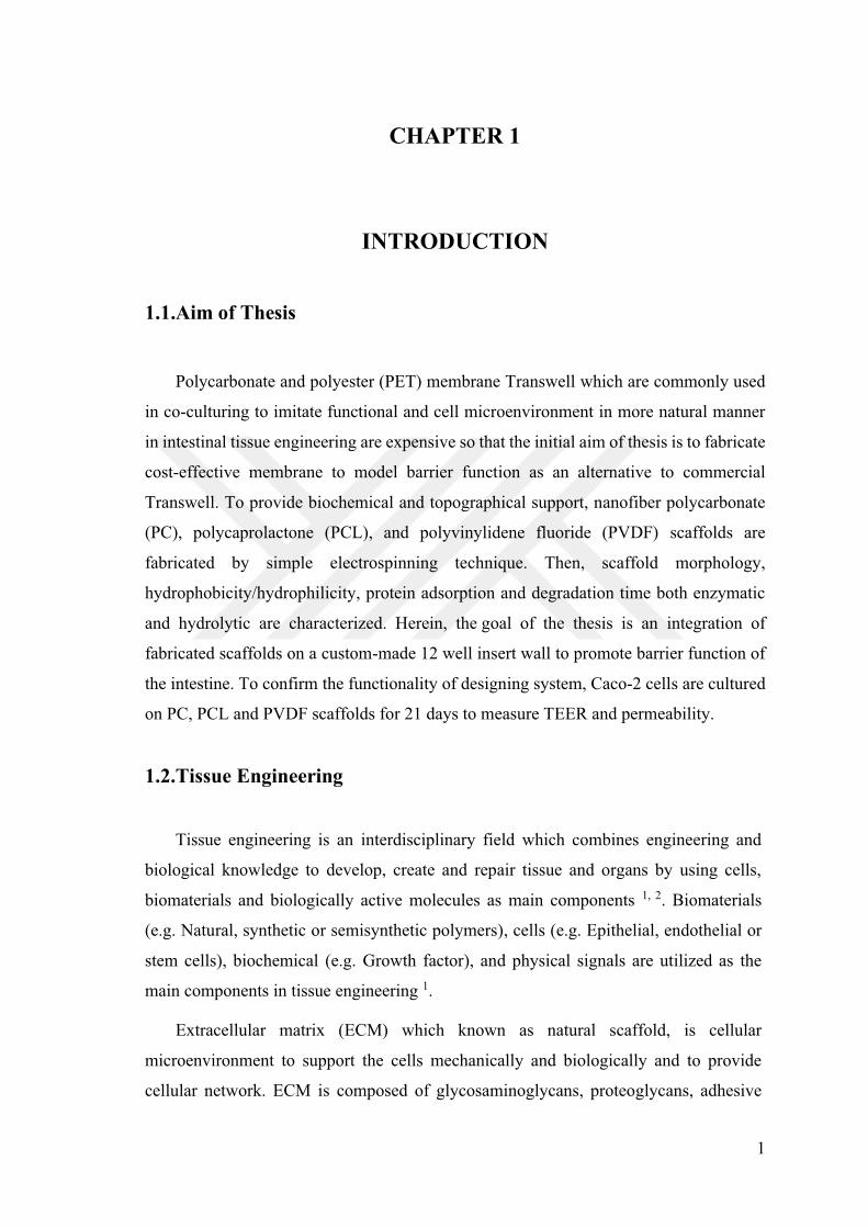
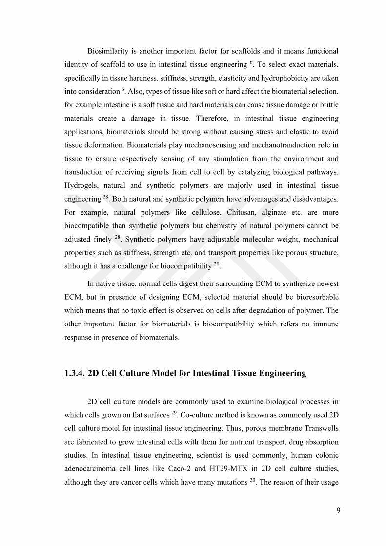
1.3.1. Anatomy and Physiology of Human Intestines
Both small and large intestines are in the lower part of the abdominal cavity. A
human intestinal system compartments and their structures are given in figure 1.1. The
small intestine is a narrow hollow tube which begins from the stomach and lies along the
pyloroduodenal junction. Then, large intestines are formed at the ileocecal junction 9.
Diameters of small intestine are 1,5 cm in newborn and 2,5-3 cm in adults. Length of
small and large intestine is 6.5 m together with adults. The small intestine is composed
of 3 parts which are duodenum, jejunum and ileum. The duodenum is the first and
shortest part of the small intestine, which is approximately 25 cm C-shaped 10. It encloses
the head of the pancreas and contains partially digested food. Also, the duodenum has 4
parts which are called as first, second, third and fourth. Acidic slurry, gastric enzymes
from the stomach, bile from the gall bladder, and pancreatic enzymes from the pancreas
are delivered from the first part of duodenum. Basic bile neutralizes the acidic slurry, so
duodenum is known as neutral or mildly acidic. As a result of this pH conditions, gastric
enzymes become inactive while pancreatic and intestinal enzymes are activated 11. The
second part is known as retroperitoneal which lateral to the pancreas and the third one is
the horizontal part that connected to abdominal wall via mesentery. The fourth part is the
last part of the duodenum where jejunum starts over here 12.
Generally, small intestines have a major function which is receiving of digested
food, digestive secretion from the liver and pancreas, digestion of received food by own
enzymes, absorption of nutrients into the blood stream. Most digestions take place in the
small intestines. Some carbohydrates are digested by pancreatic amylases and hydrolases
which are secreted from enterocytes in intestinal mucosa. Pancreatic peptidases are
activated in small intestines even though proteins, mainly digested in the stomach. Thus,
digested proteins, oligopeptides, are absorbed by the enterocytes 13. In addition to
carbohydrates and proteins, majority of lipid digestion occurs in the small intestine by
lipases and bile salts. Lipases which are responsible for digestion of lipids, are secreted
from the pancreas. Bile salts make emulsification of fats. Finally, vitamins,
micronutrients, and 60-80 % water from food are absorbed in small intestine 14.
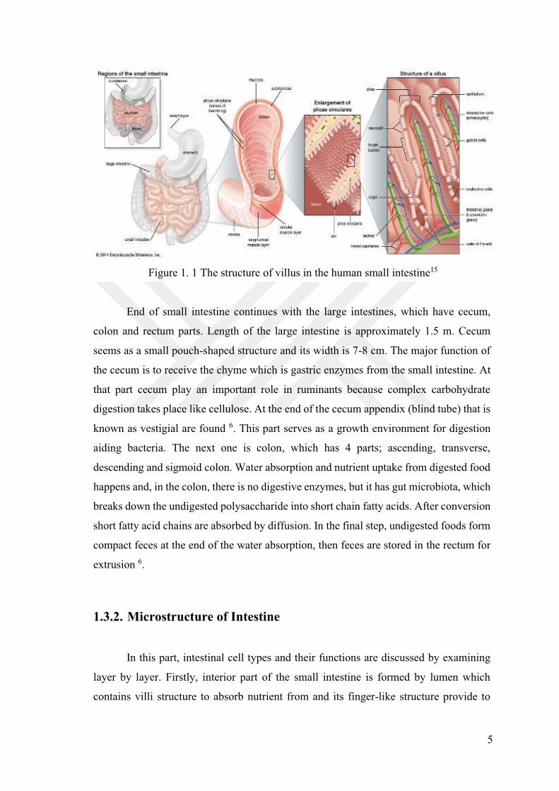
5
Figure 1. 1 The structure of villus in the human small intestine15
End of small intestine continues with the large intestines, which have cecum,
colon and rectum parts. Length of the large intestine is approximately 1.5 m. Cecum
seems as a small pouch-shaped structure and its width is 7-8 cm. The major function of
the cecum is to receive the chyme which is gastric enzymes from the small intestine. At
that part cecum play an important role in ruminants because complex carbohydrate
digestion takes place like cellulose. At the end of the cecum appendix (blind tube) that is
known as vestigial are found 6. This part serves as a growth environment for digestion
aiding bacteria. The next one is colon, which has 4 parts; ascending, transverse,
descending and sigmoid colon. Water absorption and nutrient uptake from digested food
happens and, in the colon, there is no digestive enzymes, but it has gut microbiota, which
breaks down the undigested polysaccharide into short chain fatty acids. After conversion
short fatty acid chains are absorbed by diffusion. In the final step, undigested foods form
compact feces at the end of the water absorption, then feces are stored in the rectum for
extrusion 6.
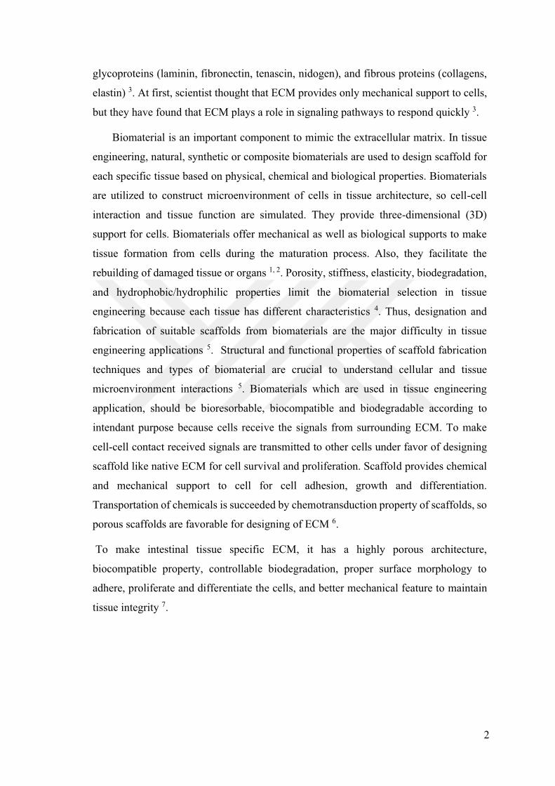
1.3.2. Microstructure of Intestine
In this part, intestinal cell types and their functions are discussed by examining
layer by layer. Firstly, interior part of the small intestine is formed by lumen which
contains villi structure to absorb nutrient from and its finger-like structure provide to
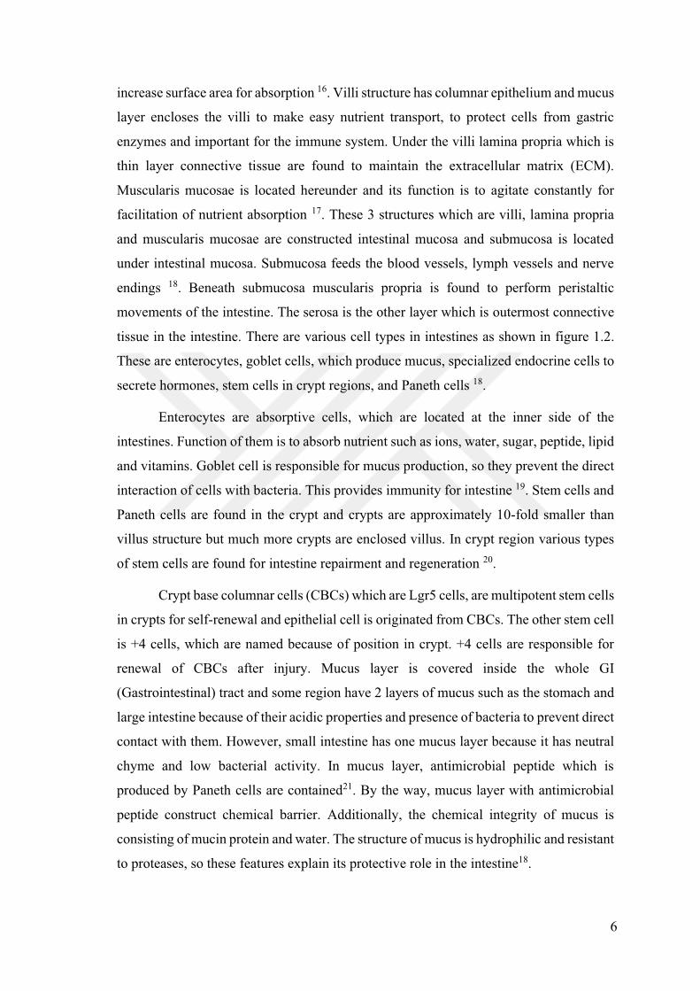
6
increase surface area for absorption 16. Villi structure has columnar epithelium and mucus
layer encloses the villi to make easy nutrient transport, to protect cells from gastric
enzymes and important for the immune system. Under the villi lamina propria which is
thin layer connective tissue are found to maintain the extracellular matrix (ECM).
Muscularis mucosae is located hereunder and its function is to agitate constantly for
facilitation of nutrient absorption 17. These 3 structures which are villi, lamina propria
and muscularis mucosae are constructed intestinal mucosa and submucosa is located
under intestinal mucosa. Submucosa feeds the blood vessels, lymph vessels and nerve
endings 18. Beneath submucosa muscularis propria is found to perform peristaltic
movements of the intestine. The serosa is the other layer which is outermost connective
tissue in the intestine. There are various cell types in intestines as shown in figure 1.2.
These are enterocytes, goblet cells, which produce mucus, specialized endocrine cells to
secrete hormones, stem cells in crypt regions, and Paneth cells 18.
Enterocytes are absorptive cells, which are located at the inner side of the
intestines. Function of them is to absorb nutrient such as ions, water, sugar, peptide, lipid
and vitamins. Goblet cell is responsible for mucus production, so they prevent the direct
interaction of cells with bacteria. This provides immunity for intestine 19. Stem cells and
Paneth cells are found in the crypt and crypts are approximately 10-fold smaller than
villus structure but much more crypts are enclosed villus. In crypt region various types
of stem cells are found for intestine repairment and regeneration 20.
Crypt base columnar cells (CBCs) which are Lgr5 cells, are multipotent stem cells
in crypts for self-renewal and epithelial cell is originated from CBCs. The other stem cell
is +4 cells, which are named because of position in crypt. +4 cells are responsible for
renewal of CBCs after injury. Mucus layer is covered inside the whole GI
(Gastrointestinal) tract and some region have 2 layers of mucus such as the stomach and
large intestine because of their acidic properties and presence of bacteria to prevent direct
contact with them. However, small intestine has one mucus layer because it has neutral
chyme and low bacterial activity. In mucus layer, antimicrobial peptide which is
produced by Paneth cells are contained21. By the way, mucus layer with antimicrobial
peptide construct chemical barrier. Additionally, the chemical integrity of mucus is
consisting of mucin protein and water. The structure of mucus is hydrophilic and resistant
to proteases, so these features explain its protective role in the intestine18.
7
Figure 1. 2 Various cell types in villus microstructure
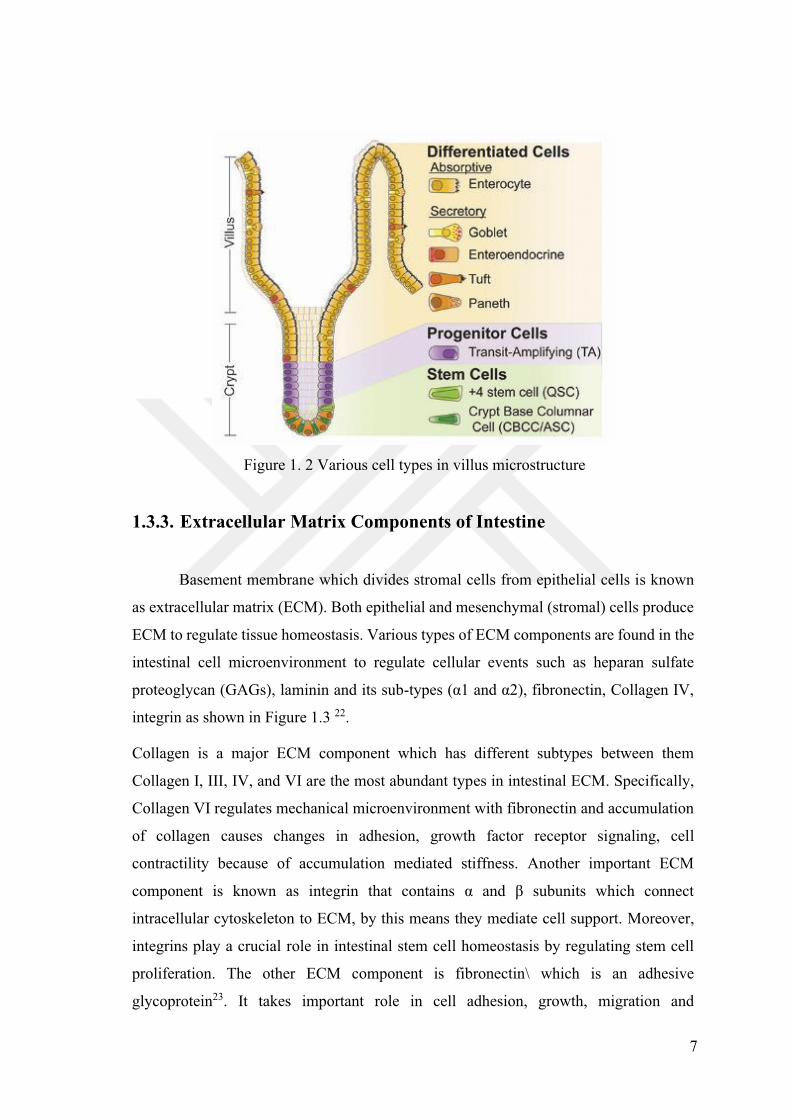
1.3.3. Extracellular Matrix Components of Intestine
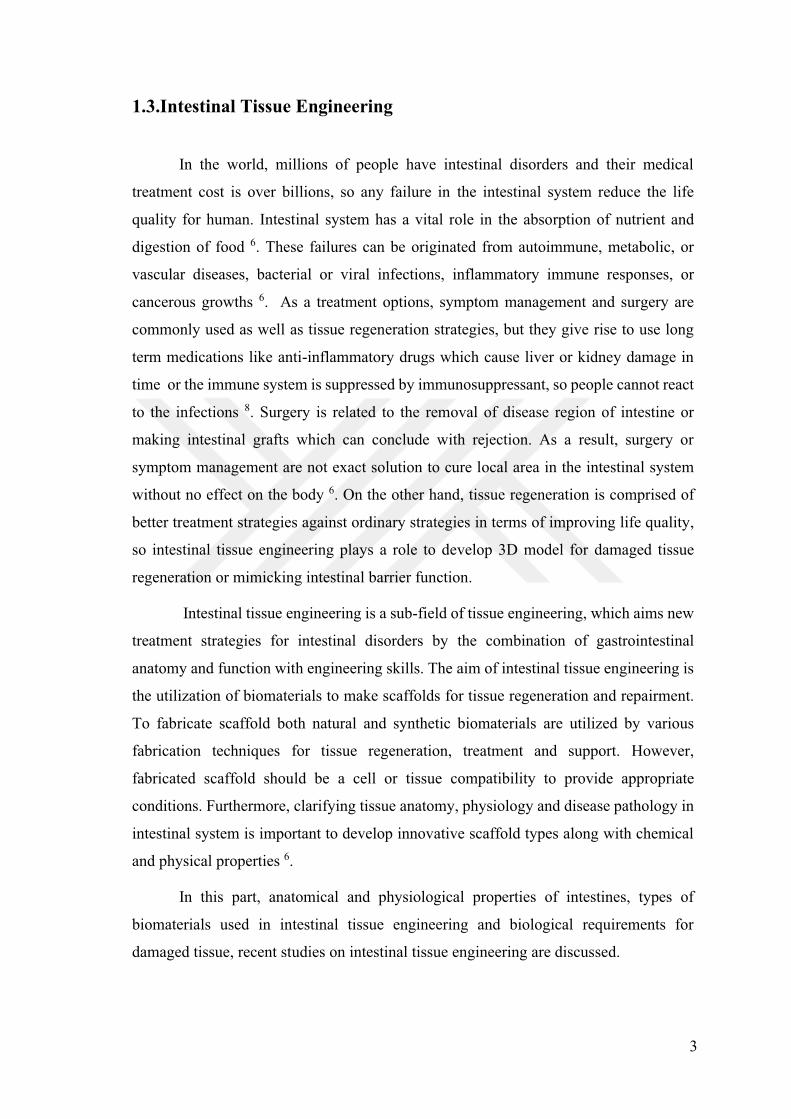
Basement membrane which divides stromal cells from epithelial cells is known
as extracellular matrix (ECM). Both epithelial and mesenchymal (stromal) cells produce
ECM to regulate tissue homeostasis. Various types of ECM components are found in the
intestinal cell microenvironment to regulate cellular events such as heparan sulfate
proteoglycan (GAGs), laminin and its sub-
integrin as shown in Figure 1.3 22.
Collagen is a major ECM component which has different subtypes between them
Collagen I, III, IV, and VI are the most abundant types in intestinal ECM. Specifically,
Collagen VI regulates mechanical microenvironment with fibronectin and accumulation
of collagen causes changes in adhesion, growth factor receptor signaling, cell
contractility because of accumulation mediated stiffness. Another important ECM
component is known as integrin that contains
intracellular cytoskeleton to ECM, by this means they mediate cell support. Moreover,
integrins play a crucial role in intestinal stem cell homeostasis by regulating stem cell
proliferation. The other ECM component is fibronectin\ which is an adhesive
glycoprotein23. It takes important role in cell adhesion, growth, migration and
8
differentiation. Fibronectin which are produced by intestinal fibroblasts, interconnect
with other ECM proteins such as GAGs, collagens, integrins. Accumulation of
fibronectin causes some intestinal diseases like Inflammatory Bowel Disease (IBD).
Moreover, fibronectin directly contact with specific signaling pathway (NF- B) that
causes inflammation. Laminin is a type of glycoprotein in ECM and mainly found in
basement membrane. It is responsible for the formation of epithelial cell polarity 24,
25.There are various laminin sub-typ re the most abundant types at
the crypt region to protect villus structure and establish mucosa. The final ECM
component is GAGs which have high viscosity and low compressibility. This feature
provides structural integrity to the cells, so cell migration is facilitated26. Heparan sulfate,
hyaluronic acid and chondroitin sulfate which are types of GAGs in intestine, promotes
intestinal regeneration 27.
Figure 1. 3 Schematic diagram of major classes of ECM components in intestine 25
9
Biosimilarity is another important factor for scaffolds and it means functional
identity of scaffold to use in intestinal tissue engineering 6. To select exact materials,
specifically in tissue hardness, stiffness, strength, elasticity and hydrophobicity are taken
into consideration 6. Also, types of tissue like soft or hard affect the biomaterial selection,
for example intestine is a soft tissue and hard materials can cause tissue damage or brittle
materials create a damage in tissue. Therefore, in intestinal tissue engineering
applications, biomaterials should be strong without causing stress and elastic to avoid
tissue deformation. Biomaterials play mechanosensing and mechanotranduction role in
tissue to ensure respectively sensing of any stimulation from the environment and
transduction of receiving signals from cell to cell by catalyzing biological pathways.
Hydrogels, natural and synthetic polymers are majorly used in intestinal tissue
engineering 28. Both natural and synthetic polymers have advantages and disadvantages.
For example, natural polymers like cellulose, Chitosan, alginate etc. are more
biocompatible than synthetic polymers but chemistry of natural polymers cannot be
adjusted finely 28. Synthetic polymers have adjustable molecular weight, mechanical
properties such as stiffness, strength etc. and transport properties like porous structure,
although it has a challenge for biocompatibility 28.
In native tissue, normal cells digest their surrounding ECM to synthesize newest
ECM, but in presence of designing ECM, selected material should be bioresorbable
which means that no toxic effect is observed on cells after degradation of polymer. The
other important factor for biomaterials is biocompatibility which refers no immune
response in presence of biomaterials.
1.3.4. 2D Cell Culture Model for Intestinal Tissue Engineering
2D cell culture models are commonly used to examine biological processes in
which cells grown on flat surfaces 29. Co-culture method is known as commonly used 2D
cell culture motel for intestinal tissue engineering. Thus, porous membrane Transwells
are fabricated to grow intestinal cells with them for nutrient transport, drug absorption
studies. In intestinal tissue engineering, scientist is used commonly, human colonic
adenocarcinoma cell lines like Caco-2 and HT29-MTX in 2D cell culture studies,
although they are cancer cells which have many mutations 30. The reason of their usage
10
is originated from differentiation ability of Caco-2 cells into enterocyte-like cells and
HT29-MTX into mucus produced goblet cells 31.Caco-2 cells were isolated from large
intestines, but they differentiate into enterocyte-like cells. Differentiation ability provides
the advantage to mimic small intestine cells. Additionally, Caco-2 cells are able to form
tight junctions between neighboring cells and produce digestive enzymes such as
sucrase-isomaltase, lactase, peptidase, and alkaline phosphatase 32. Caco-2 cells are used
to imitate small intestinal enterocytes and in nutrient and pharmaceutical ingestion and
transport studies30.
In intestinal modelling, the other commonly used cell line is HT29-MTX cells.
They were isolated from human colonic adenocarcinoma and they are methotrexate
(MTX) resistant cells. HT29-MTX cells are entirely differentiated to goblet cells, which
secrete the mucus. Generally, they combine with Caco-2 cells to make co-culture model
for mimicking intestinal system. HT29-MTX cells were used to test the muco-adhesive
and toxicity of nanoparticles, the diffusion of drugs towards the mucus layer 30.
Co-cultured Caco-2 and HT29-MTX in Transwell inserts has been studied to
mimic native small intestinal epithelium on 2D cell culture monolayer 30. The cells have
been formed irregular microvilli-like structures. HT29-MTX cells produced a mucus
layer with Caco-2 cells and they have a role in digestion, drug absorption model, drug
permeability and bioavailability studies 30. Moreover, co-culture of Caco-2 and HT29-
MTX provide the most physiologically important in vivo conditions for intestinal tissue
engineering 33.
The villus morphology does not establish effectively by Transwells because of
being 2D static cell culture models. Due to lack of a 3D microenvironment, intestinal
cells cannot undergo differentiation on Transwells. Thus, scientist has begun to develop
bioengineered 3D models for mimicking human intestinal system 34.
1.3.5. 3D Cell Culture Models for the Intestinal Tissue Engineering
Due to the weakness of 2D cell culture for intestinal remodeling, the complex
architecture of the small intestine is simulated by constructing 3D models to model in
vivo phenotype of human intestine.35 To develop a small intestine tissue structure and to
11
mimic intestine tissue microenvironment scaffolds provide mechanical and biological
support to cells for tissue network formation. There are several factors need to be
considered to develop scaffolds such as porosity, topography and biochemical cues for
intestinal 3D structure. These factors affect cell-cell interaction tissue formation,
differentiation and better tissue or organ responses 30. The main disadvantages of
mimicking of human intestine are that the topography of the intestine has not been
created totally. As is known, physical environment related to morphology, biochemical
property and metabolism of native tissue environment. The other factor to realize natural
intestine system mimicking models is that villus structure which play a role in intestinal
fluid dynamics, pressure and wall stiffness 36.
Scaffold porosity, which is the main factor, plays role in cell fate by providing
the 3D scaffold architecture. Porous structure of fabricated 3D scaffold helps intestinal
cells to diffuse inside 3D scaffolds and pore size is an important parameter because pores
create holes in scaffolds37. Cells penetrate the matrix and cells synthesize own
extracellular matrix. Therefore, there are many studies to produce porous biomaterials
which support the cells the mechanically and physically to adapt the small intestine30.
However, the cell growth, differentiation and formation of tissue from cells varies
according to used scaffolds 30. Each biomaterial has specific properties to adhere the cells
by regulating cell-and-scaffold interaction. Synthetic polymers can have additional
bioactive species such as peptides, proteins or carbohydrates which promotes biological
response or natural polymers such as collagen chitosan have similar biochemical
properties, so cells can easily adapt and adhere to them 6, 38. Scaffolds investigated to
date include natural hydrogels such as collagen, alginate etc. and synthetic scaffolds such
as poly-lactic-glycolic acid, polycaprolactone, polycarbonate which have a range of main
advantages and disadvantages 6, 30. For example, Kim and co-workers have fabricated a
cell culture well insert with a collagen gel-coated and aligned PCL nanofiber membrane
which is called Col-ANM to model intestinal barrier 39.
Collagen is known as widely used natural polymer for 3D culture because they
are simple to prepare and cost-effective, support a variety of cell types and proper for
cell encapsulation. Also, the collagen concentration or pore sizes, rigidity and ligand
density can be modified. Firstly, Collagen gels were used in the seeds of fibroblasts,
12
Caco-2 and HT29-MTX 40. This 3D co-culture model has been used to assess drug
permeability and shown that drug absorption rates are more physiologically relevant.
All these approaches do not replicate the small intestine villus-crypt architecture.
Thus, to overcome this problem, Wang and co-workers investigated the effect of a
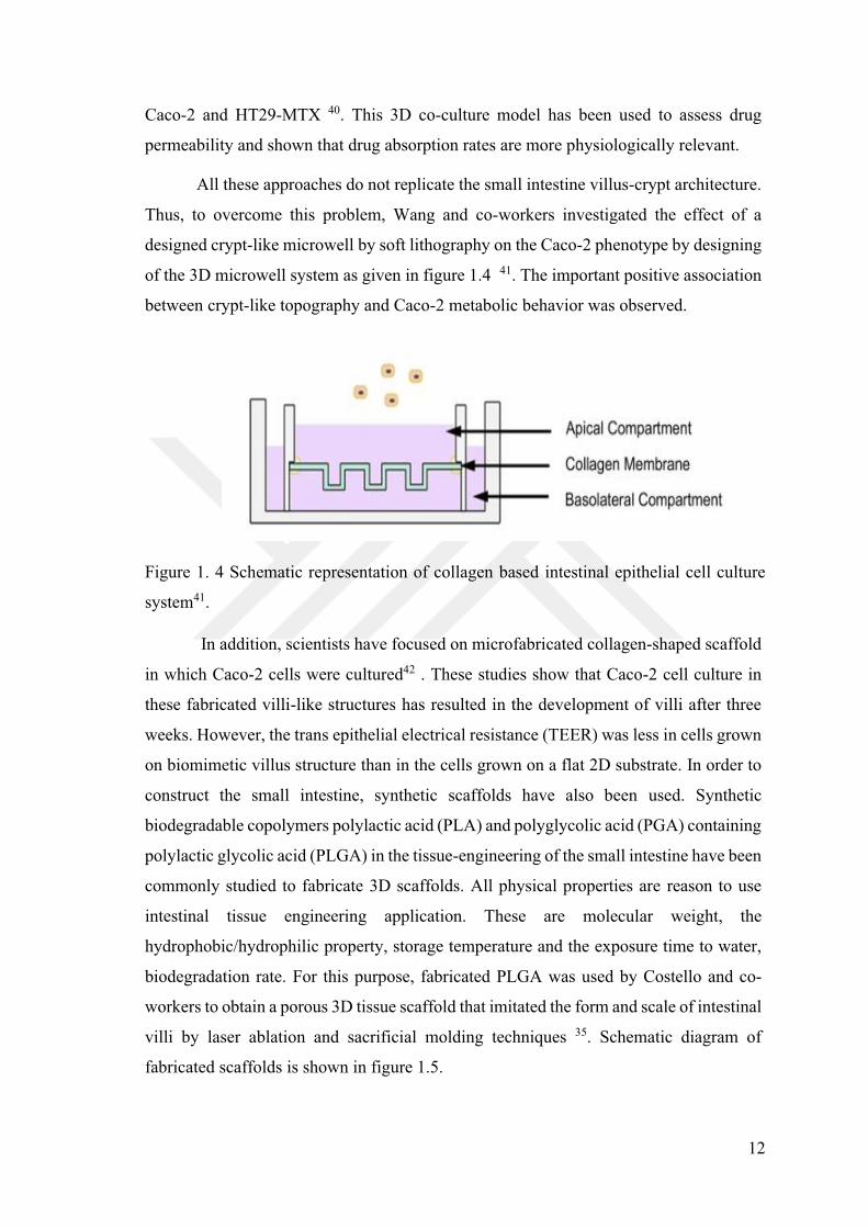
designed crypt-like microwell by soft lithography on the Caco-2 phenotype by designing
of the 3D microwell system as given in figure 1.4 41. The important positive association
between crypt-like topography and Caco-2 metabolic behavior was observed.
Figure 1. 4 Schematic representation of collagen based intestinal epithelial cell culture
system41.
In addition, scientists have focused on microfabricated collagen-shaped scaffold
in which Caco-2 cells were cultured42 . These studies show that Caco-2 cell culture in
these fabricated villi-like structures has resulted in the development of villi after three
weeks. However, the trans epithelial electrical resistance (TEER) was less in cells grown
on biomimetic villus structure than in the cells grown on a flat 2D substrate. In order to
construct the small intestine, synthetic scaffolds have also been used. Synthetic
biodegradable copolymers polylactic acid (PLA) and polyglycolic acid (PGA) containing
polylactic glycolic acid (PLGA) in the tissue-engineering of the small intestine have been
commonly studied to fabricate 3D scaffolds. All physical properties are reason to use
intestinal tissue engineering application. These are molecular weight, the
hydrophobic/hydrophilic property, storage temperature and the exposure time to water,
biodegradation rate. For this purpose, fabricated PLGA was used by Costello and co-
workers to obtain a porous 3D tissue scaffold that imitated the form and scale of intestinal
villi by laser ablation and sacrificial molding techniques 35. Schematic diagram of
fabricated scaffolds is shown in figure 1.5.
13
Figure 1. 5 Schematic illustration of porous PLGA intestinal scaffold formation35
They demonstrated the co-cultured Caco-2 and HT29-MTX on PLGA villi
shaped scaffold cell proliferation and differentiation. These Caco-2 and HT29-MTX
cells, however, were separated by applying epidermal growth factor stimulation to the
basolateral side of the scaffold. Cellular differentiation along the villus axis was observed
on PLGA scaffold as well as nature of native intestines. Additionally, they exhibited that
biochemical and physical microenvironments of the intestine can be mimicked with both
apical and basolateral feedings of intestinal cell types cultured on these types of models35.
The other examples of 3D intestinal models were fabricated by Sung and co-
workers by using laser ablation to create holes and sacrificial molding as shown in figure
1.6. The novelty of this method is that they combine natural (collagen and alginate) and
synthetic polymer (PEG-DA) to mimic villus structure and alginate was used as a
sacrificial hydrogel under physiological conditions 43.
14
Figure 1. 6 Schematic of fabrication process43.
The study of physiological and functionally mimicked intestinal model drug
absorption tests, and toxicity studies, such models are highly useful. However, they lack
the modelling of the in vivo environment to date, totally. In order to develop naturally
similar intestinal tissue which is composed of mucosa, neuromuscular tissue and
microbiota, advanced 3D models and new methods are needed.
The other prominent model which is given in figure 1.7, was established by Yu
and co-worker. 3D villus platform was constructed by using collagen type I. Also, in this
model alginate was used as a sacrificial layer to obtain villus structure. This platform is
known as first accurate 3D villus model to offer a well-controlled microenvironment and
to provide highly physiological relevance to the in vivo system 44.
15
Figure 1. 7 Schematic of insert design44
1.3.5.1.Co-culture
Scientists have constructed models which consist of co-culturing different types
of cells like immune or mesenchymal cells with intestinal epithelial cells on fabricated
hydrogels, porous membranes to illustrate paracrine communication of them 45. Some
studies showed that intestinal epithelial cells have been co-cultured with vascular cells on
fabricated scaffolds in microfluidic or Transwell systems to simulate the human intestinal
system function. Interaction of different intestinal cells has been examined by using co-
culturing system to understand their cross-talking in real intestine. By the way Transwell
system which is permeable support has been developed to observe heterotypic cell
interaction. All of models can be used in drug absorption, nutrient absorption or disease
models 46. The aim of the co-culture method is to demonstrate the interaction of cells by
biochemical signals and to examine tissue formation process with different cells to model
intestinal tissue.
16
1.3.5.2. Microfabrication
In recent studies, photolithography has been used as a microfabrication technique
to construct crypt-villus architecture. Wang Y. and coworkers have created crypt-villus
structure on collagen microwell scaffold of modified Transwell insert and Caco-2 cells
were cultured on this microfabricated collagen scaffold. They used photolithography and
micro molding techniques. Crosslinked-collagen hydrogels support the intestinal cell as
an extracellular matrix 47. In this study, cells showed that metabolic activity increased and
transepithelial resistance value decreased when compared with a flat surface.
Figure 1. 8 Schematic of the process used to generate the PDMS stamp to micro mold
the collagen47
oworkers have fabricated 3D structure with soft hydrogels
by using laser ablation and sacrificial molding techniques. The novelty of this 3D
architecture is about the usage of solvable for the calcium alginate as a secondary mold
to obtain soft structure 43.
Later, to evaluate the integrity and the role of the 3D model in predicting drug
permeability, the same group adapted the collagen scaffold to an insert design.
Maintaining Caco-2 cells on the scaffolds for 21 days did not shorten the villi and
promoted the formation of multiple layers caused by cell penetration in the matrix as the
17
collagen degraded. This led to a higher permeability of the tested hydrophilic drug, when
compared with the data from 2D cultures, approximating the values obtained for
mammalian intestines. Moreover, they reported that cell differentiation on the 3D scaffold
varied along the villus 44.
The studies also explored the recreation of the intestinal microenvironment for the
differentiation of cells. More recently, a micropatterned collagen scaffold with a crypt-
villus architecture and an adequate chemical gradient promoted the formation of a
stem/progenitor-cell zone and supported cell migration along the crypt-villus axis 48
The same group employed the PLGA scaffolds to study cell behavior and drug
absorption of the Caco-2 and HT29-MTX co-culture model. They observed that the two
epithelial cell types on the scaffolds were able to mimic the morphology and
differentiation profile verified in native intestinal tissue, as identified by the expression
of differentiation markers and by mucus secretion 42.
The other research group has investigated the absorptive and metabolic properties
of Caco-2 cells cultured in the collagen hydrogel scaffolds and in monolayers. Cell
growth was higher in the 3D villi model comparison with 2D and its barrier function was
similar to natural intestine and the activity of the metabolic enzymes was also improved
in the 3D models.49

18
CHAPTER 2
MATERIALS AND METHODS
2.1. Materials
Dimethylformamide (DMF, Sigma Aldrich), Tetrahydrofuran (THF,
Sigma Aldrich), Acetone ( Sigma Aldrich), and Chloroform ( Sigma
Aldrich) were used as a solvent to prepare polymer solutions. Electrospinning device
(Inovenso NE300) was used to obtain PC, PCL and PVDF nanofibers. Lysozyme from
chicken egg white in the form of lyophilized powder ( 90%, 40.000 units/mg protein,
Sigma Aldrich) was used for enzymatic degradation studies. BCA protein kit
(Bicinchoninic Acid, Pierce Thermo) and BSA as lyophilized powder (Bovine serum
albumin, Sigma Aldrich) were used for protein adsorption analysis. 1X phosphate buffer
saline (PBS, pH 7.4 Gibco-Thermo Fischer) was used for hydrolytic biodegradation,
cleaning and solubilizing agent for protein adsorption analysis. Sodium dodecyl sulfate
(SDS, Bioshop), Tween 20 (Bioshop) and Triton X-100 (Bioshop) were used for
solubility analysis in protein adsorption assay. For cell culture analysis; Caco-2 cell line
-37 ), Minimum Eagle's Medium (MEM, Sigma Aldrich), fetal bovine
serum (FBS-Gibco), penicillin-streptomycin (Sigma Aldrich), trypsin EDTA solution
(Sigma Aldrich) and sodium pyruvate (Sigma Aldrich) were used for cell culture studies.
Dimethylsulphoxide (DMSO, Carlo Erba) was used for cell freezing medium. In vitro
cell proliferation and viability was analyzed with resazurin sodium salt from ChemCruz,
and CytoCalcein AM and Propidium Iodide dye (AAT Bioquest) used for live/dead assay.
0.4-mm pore-size collagen-coated and PET trans-well inserts (Corning) was used in 12-
well plate Transepithelial resistance was measured by Evom2 meter (World Precision
Instruments). Phenol red (Sigma Aldrich) was used for transport experiment. Anti-
Collagen Type I-FITC Antibody, FAK100 Actin Cytoskeleton Focal Adhesion and DAPI
staining kit were purchased from Sigma Aldrich.
19
2.2 Methods
2.2.1. Fabrication of PCL, PVDF, and PC Scaffolds
Polycaprolactone (PCL), polyvinylidene fluoride (PVDF) and polycarbonate (PC)
were fabricated by using electrospinning technique. Firstly, 4.6 grams of PVDF were
dissolved in 12 ml DMF and 3 ml acetone in vial, and the mixture was put on to magnetic
stirrer fter PVDF completely dissolved, solution
transferred to the 20ml syringe. Then, the collector coated with aluminum foil to start
electrospinning. There are various electrospinning parameters to consider; flow rate,
voltage, tip collector distance and homogeneity mode of collector and rotation were
adjusted to 10ml/h at 38mm diameter,25kV, 170mm and 500 rpm respectively. Secondly,
3,7 grams of PCL (18.5wt %) was dissolved in 20 ml Chloroform. Solution was stirred
on magnetic stirrer at 30 . After 3 hours, PCL dissolved homogenously,
and electrospinning device was prepared to fabricate nanofiber mat. Collector coated with
aluminum foil. Electrospinning parameters were adjusted to 8ml/h flow rate at 38mm
diameter and voltage was 25kV, tip collector distance was 150mm and homogeneity
mode of collector and rotation are turned on at 500 rpm. Finally, 15 mL of 15wt% PC
solution was prepared by using THF: DMF (3:2) in 20 ml vial and solution put on to the
magnetic stirrer for overnight at . When PC completely dissolved,
solution transferred to the 20ml syringe and the collector coated with aluminum foil.
Electrospinning parameters were adjusted to 8ml/h flow rate at 38mm diameter and
voltage was 25.6 kV, tip collector distance was 180mm and homogeneity mode of
collector and rotation are turned on at 500 rpm. After electrospun nanofiber PCL, PVDF,
and PC scaffolds were obtained, and were dried at r
2.2.2. Characterization Tests
2.2.2.1. Scanning Electron Microscopy (SEM) Analysis
Surface morphology of scaffolds and fiber diameter were analyzed by scanning
electron microscope (SEM- Quanta FEG 250) by using Image J Software (NIH).
20
Scaffolds were cut and fixed on carbon bands and coated with thin gold layer under
argon gas (Emitech K550X). Scaffolds were analyzed in varied magnifications.
2.2.2.2 Contact Angle
Water contact angle is used to measure surface hydrophilicity of scaffolds and
distilled water used as a reference liquid. The instrument (Attension) that was used in this
analysis as a manual mode and 5 l distilled water was dropped on to the scaffold surface.
Separately, PCL, PVDF and PC scaffolds were fixed on glass lam by using double side
adhesive bands to obtain smooth surface. Then, the angle between water drop and surface
of the scaffolds was measured for 10 seconds time interval and the average value was
evaluated.
2.2.2.3. Protein Adsorption
Protein adsorption assay was utilized to display cell adhesion and proliferation on
to nanofiber scaffold surfaces. According to the instructions; 4 mg of BSA dissolved in
2mL 1X PBS which was prepared as a stock solution Dilution series were prepared
according to Table 2.1.
Table 2.1 Bovine serum albumin (BSA) standards preparation
Test Tubes
Volume of 1X PBS
Volume of Source of
Final BSA Concentration
A 0 300 of stock 2000 B 125 375 of stock 1500 C 325 325 of stock 1000 D 175 175 of test tube B
dilution 750
E 325 325 of test tube C dilution
500
F 325 325 of test tube E dilution
250
G 325 325 of test tube F dilution
125
21
H 400 100 of test tube G dilution
25
I (Blank) 400 0 0
PVDF, PCL and PC scaffolds were cut into 6 mm diameter of round shapes by
puncher and placed in 96 well plate. For each concentration 3 replications were prepared.
separated to measure the initial solution without
scaffolds. 75 well plate, scaffolds
25 ere
taken to measure final concentrations. At the same time scaffolds were removed from
solutions and washed three times in 1X PBS. Then immersed into 75 SDS
detergent solution.
as detergent solubilized samples. WR (Working reagent which contain Reagent A:
Reagent B (50:1)) is prepared according to the number of working wells. After addition
concentration)
which contained PC, PCL and PVDF scaffolds. Solutions were covered aluminum foil
and incubated After that solutions cooled to room temperature, the
absorbance was measured at 562 nm for each well on a plate reader.
2.2.3. Microdevice Fabrication
To use in co-culturing of intestinal cells as an alternative to commercial Transwell
New 3 layers Transwell insert was designed inspired by commercially available
Transwell insert. Initially, 3.4 mm thick PMMA circles were cut via laser cutter. The first
PMMA circle was placed into12- well plate insert bottom end figure 2.1
step 1. Then, 13 mm diameter of electrospun PC, PCL and PVDF nanofiber scaffolds
were cut and sterilized by UV in 30 minutes for 2 times for each side, place onto PMMA
circle as given in figure 2.1 step 2. After placement of scaffolds, same sized PMMA circle
was placed onto the scaffold, so scaffold was sandwiched by two PMMA circles as
indicated in step 3 of figure 2.1. At the end of steps, separate microdevice was constructed
from 3 different electrospun PC, PCL and PVDF scaffolds. To use in cell culture studies.
Each side of insert was sterilized by UV in 30 min for 2 times.
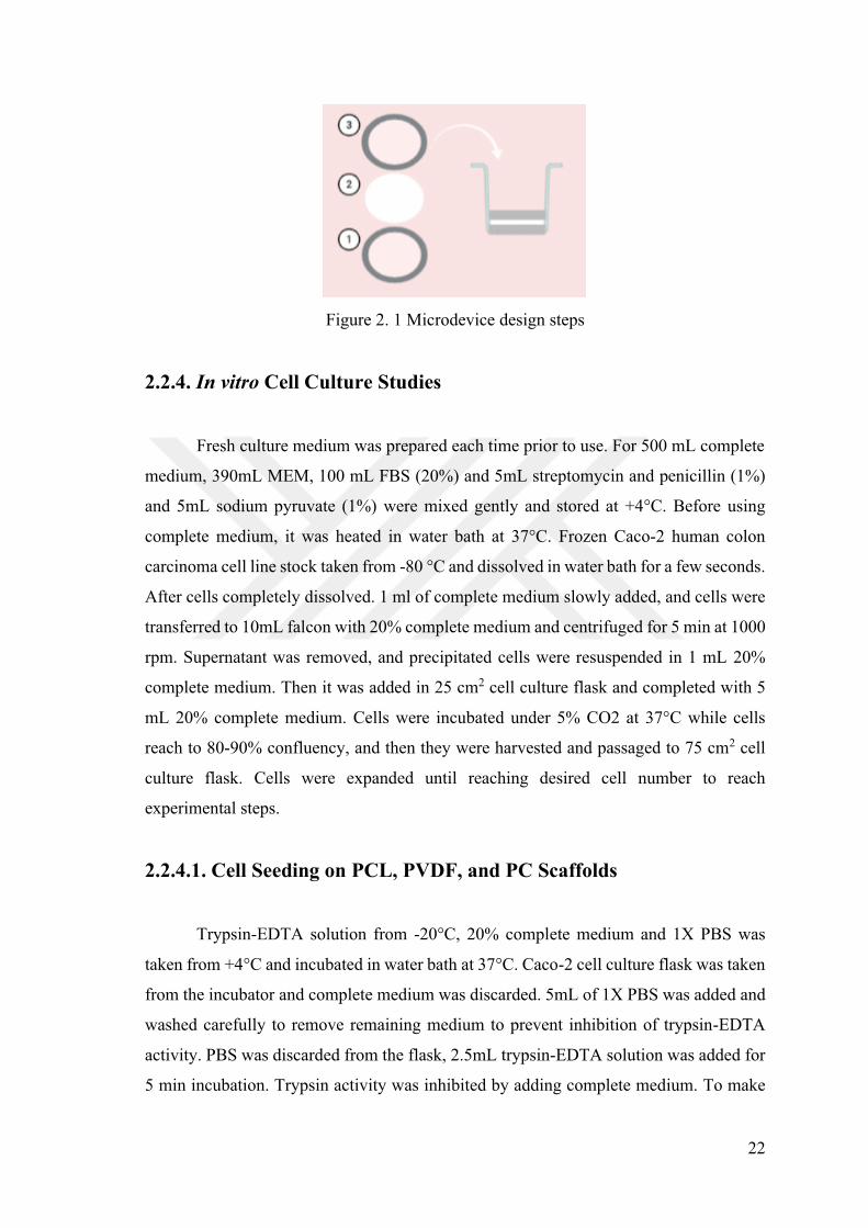
22
Figure 2. 1 Microdevice design steps
2.2.4. In vitro Cell Culture Studies
Fresh culture medium was prepared each time prior to use. For 500 mL complete
medium, 390mL MEM, 100 mL FBS (20%) and 5mL streptomycin and penicillin (1%)
and 5mL sodium pyruvate (1%) were using
complete medium, it was heated in water bath a Caco-2 human colon
carcinoma cell line stock taken from - for a few seconds.
After cells completely dissolved. 1 ml of complete medium slowly added, and cells were
transferred to 10mL falcon with 20% complete medium and centrifuged for 5 min at 1000
rpm. Supernatant was removed, and precipitated cells were resuspended in 1 mL 20%
complete medium. Then it was added in 25 cm2 cell culture flask and completed with 5
mL 20% complete medium. Cells were incu
reach to 80-90% confluency, and then they were harvested and passaged to 75 cm2 cell
culture flask. Cells were expanded until reaching desired cell number to reach
experimental steps.
2.2.4.1. Cell Seeding on PCL, PVDF, and PC Scaffolds
Trypsin-EDTA solution from - 20% complete medium and 1X PBS was
incubated Caco-2 cell culture flask was taken
from the incubator and complete medium was discarded. 5mL of 1X PBS was added and
washed carefully to remove remaining medium to prevent inhibition of trypsin-EDTA
activity. PBS was discarded from the flask, 2.5mL trypsin-EDTA solution was added for
5 min incubation. Trypsin activity was inhibited by adding complete medium. To make
23
cell counting Trypsin activity inhibited cell and complete medium mixture centrifuged at
1000rpm for 5 min. Then supernatant was discarded, and precipitated cells were
suspended in 1mL cell medium, resuspended cells were diluted to 1:10 ratio with cell
solution was loaded in hemocytometer and counted.
To make cell seeding on PCL, PVDF and PC scaffolds, Scaffolds were cut in
round shape to fit in 96 well plate and their sterilization was applied under ultraviolet
light (UV-245nm) for 30 min for each side and 3 times.
Also, scaffolds were immersed into 1X PBS to wet the scaffolds for 1 days. Each
scaffold placed in 96 well plate and each of them have 3 replicates 2*105 cells/per well
seeded over scaffolds with 20% compl
remove dead cells
and metabolic product.
2.2.4.2. Cell Proliferation and Viability on PCL, PVDF, and PC
Scaffolds
To analyze cell proliferation and behavior on scaffolds were examined by short-
term and long-term cell culture studies with Caco-2 cell line. Short-term cell culture
studies were performed for a week in 96-well plate. In each well 1*105 cells were seeded
on scaffolds. Alamar blue and live/ dead assays were used to analyze cell viability.
Alamar Blue assay is a fluorometric and colorimetric method which contains a blue non-
fluorescent resazurin reagent to investigate the cell proliferation and viability.
Fluorometric features of assay provide to measure absorbance to show cell proliferation
profiles during cell culture studies. Viable cells metabolites blue resazurin into resorufin
and it alters the culture medium from blue to pink. If viable cells increase, resorufin
production increases as well. According to the protocol, Alamar blue
complete medium was added on to cell seeded the scaffold, so final concentration of
alamar blue was obtained as 0,01%. As a negative control, only Alamar blue and complete
medium was added onto PC, PCL and PVDF scaffolds without Caco-2 cell. The other
negative control contains Alamar Blue and fresh cell medium without cell and scaffolds.
All samples were incubated for 2-4 hours at 37 C After incubation, solutions were
transferred to clean well to measure absorbance at 570 and 600 nm via micro plate reader.
Then, % cell viability was calculated based on absorbance value with the equation 1;
24
(1)
Second cell viability assay was live-dead Assay which gives the qualitative
analysis of living and dead cells through fluorescence microscopy images. In Live-Dead
Assay, mixed at equal proportions
in buffer solution. Then, 3 -Dead Assay mixture
were added onto cell seeded scaffolds
incubation scaffolds were transferred onto slide and was examined by fluorescence
microscope (Carl Zeiss, Germany).
2.2.4.3. DAPI/F-Actin/Collagen I Staining of Caco-2 cells on PC, PCL
and PVDF Scaffolds
To investigate cytoskeletal organization and Collagen I as a major ECM
component synthesis of fixed Caco-2 cells for 1, 7, 14- and 21-days incubation. When
Caco-2 cells were cultured on fabricated PC, PCL and PVDF scaffolds became
approximately 50-60 % confluent, cultured cells medium was discarded, and cell were
fixed with 4 % Paraformaldehyde in 1X PBS for 15-20 minutes at room temperature and
they were rinsed with 1X PBS for 3 times. Then, permeabilizations of 3D structures of
cells was done by 0.1 % Triton X-100 in 1X PBS for 1-5 minutes at room temperature.
Wash buffer was prepared by dissolving of 0,05 % Tween20 in 1X PBS and
permeabilized cells were washed with wash buffer for 2 times. Then, Blocked with1%
BSA in 1X PBS for 30 minutes at room temperature. TRITC-conjugated Phalloidin with
1:1000 dilution was applied for 30-60 minutes at room temperature and rinsed for 3 times
with wash buffer and each was taking 5-10 minutes. nti-collagen Type I-FITC
was added into each well for 30-60 minutes and rinsed for 3 times with wash buffer for
5-10 minutes. In the last step, DAPI was performed with 1:1000 dilution for 1-5 minutes
at room temperature and rinsed with wash buffer for 3 times (5-10 minutes each). Finally,
3D barrier structures which were formed from Caco-2 cells on PC, PCL and PVDF
scaffolds with 2D control group were examined by fluorescence microscope (Carl Zeiss,
Germany)
25
2.2.4.5. Cell Seeding on PCL, PVDF, and PC Membrane Containing
Transwell Inserts
To model 3D intestinal barrier function, designed 3-layer Transwell inserts were
taken into sterile field to seed Caco-2 cells onto PC, PCL and PVDF membrane. Before
cell seeding, Transwell inserts which are suitable for 12-well plate, were sterilized with
UV for each side in 30 minutes. Conditioning procedure with 20% FBS contained MEM
medium was applied for each Transwell insert and medium was removed from inserts
completely. After conditioning of membranes, only 1x10⁵ Caco-2 cells were seeded onto
membrane without extra medium and cell adaptation was applied for 3 hours. When cells
were adapted on scaffolds for 3 hours dium was added into upper
compartment of insert and 1.5 mL of medium was added into lower part of Transwell
inserts. 21 days cell proliferation and differentiation behavior of Caco-2 cells were
observed.
2.2.4.6. TEER Measurement of Caco-2 cell line seeded PCL, PVDF,
and PC Membrane Containing Transwell Inserts
To analyze barrier function of cells after 21 days, TEER values of each Transwell
was measured. Caco-2 cell seeded PC, PCL and PVDF Transwell insert were cultured for
21 days and each 7 days Transepithelial electrical resistance (TEER) was measured with
an Evom meter (World Precision Instruments) for each experimental setup. Medium of
inserts apical and basolateral sides were refreshed gently every 2 or 3 days if medium are
consumed. Maximum TEER are measured after 14 days although cells reach confluency
at 7 days. As a blank, cell free medium containing PC, PCL and PVDF Transwell inserts
were used for baseline value and v cm2.
2.2.4.7. Phenol Red Transport
Phenol red permeability assay is used to verify monolayer integrity and to assess
tight junction integrity by measuring of phenol red across the membrane. By using
this technique cell free membrane permeability and Caco-2 cell cultured scaffold
permeability were measured to investigate or compare. For this purpose, 3

26
Red was prepared for upper compartment of Transwell
phenol red was dissolved in 4,925 mL Krebs-Ringer (uptake) buffer. Krebs-Ringer
(uptake) buffer was prepared by using 130 mmol/L NaCl, 10 mmol/L KCl, 1
mmol/LMgSO4, 5 mmol/L glucose, and 50 mmol/L HEPES at pH 7.0 ref. Then, 1,5 mL
Krebs-Ringer (uptake) buffer was added into lower compartment
to calculate phenol red
efflux of fabricated scaffolds. To measure the phenol red transport 0h, 15 and 30 min, 1,
2, 4, 8, 16, 24 hours samples were collected from lower compartment. After incubation
periods, solutions were transferred to clean well to measure absorbance at 560 nm via
micro plate reader.
27
CHAPTER 3
RESULT AND DISCUSSION
3.1. Fabrication of PC, PCL and PVDF Scaffolds
Electrospinning method is systematic, rapid, easy-to-use and versatile technique
to fabricate nano- and micrometer scale nanofibers. Optimization of electrospinning
parameters are the first strategy for electrospinning method. To optimize the scaffold
fabrication parameters solvent type and ratio, concentration of polymers was designated.
Three different polymers; PC, PCL and PVDF were determined to use as a scaffold for
intestinal tissue engineering application. PCL has wide-range usage in biomedical
applications owing to biologically compatible, biodegradable and implantable properties 50. Many solvents are used in electrospinning process of PCL such as DCM,
trifluoroethanol (TFE), hexafluoro-2-propanol (HFP) 50. These types of solvents are toxic
organic solvents, so application in biological system is difficult. Lately, environmentally
friendly, nonhazardous solvents were preferred particularly for tissue engineering
applications. Acetone, acetic acid (AA) and formic acid (FA) are relatively nonhazardous
and less toxic solvents against other organic solvents. Also, Acetic acid and formic acid
have the lowest toxicity when compared with the other solvents such as DCM, Methyl
chloride, DMF etc. Therefore 4 different solvents which are acetone, acetic acid, formic
acid and chloroform were used to obtain electrospun nanofiber scaffolds. For this
purpose, 20% PCL (w/v) solution was prepared by dissolving within mixture of AA/FA
(1:9 v/v). At this time PCL solution was incubated at room temperature for 3 hours to
prevent PCL degradation and bead formation. Electrospinning parameters were adjusted
to 6ml/h flow rate, 15 cm distance, 500rpm rotation speed and 24kV. However,
experiment was unsuccessful because voltage cannot be increased to 32kV for effective
and continuous electrospinning. Then, another solvent which is acetone was applied and
12% PCL (w/w) solution was prepared with acetone at 5ml/h and 8ml/h flow rates, 15 cm
distance, 500rpm rotation speed and 24kV. During electrospinning process, Taylor cone
28
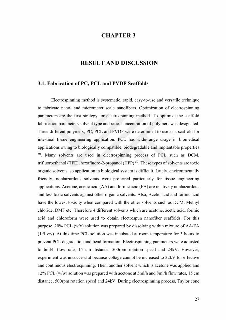
seems as a pendant and solution was dried immediately after applying voltage, so
electrospinning of PCL dissolved in acetone was not continuous. When SEM images of
PCL at 5 and 8ml/h flow rate was taken, bead formation was observed clearly for both
results as given in Figure 3.1. Flow rate is an important parameter to obtain clear fiber
shape and porosity. If flow rate increases, porosity and fiber diameter also increase 51, 52.
Figure 3. 1 SEM images of electrospun 12%wt PCL scaffolds dissolved in acetone and
electrospun at different flow rates; 5ml/h (A, C and E) 8 ml/h (B, D, and F) (scale bar =
from top to bottom)
Additionally, high flow rate leads to formation of bead structure but bead
formation cannot be eliminated by changing flow rate 52. In 12%wt PCL in acetone has
large number of bead formation, so scaffolds were shown mechanically unstable to use.

29
To overcome bead formation, chloroform was used as a solvent. 20%wt PCL
electrospinning was not proceeded effectively because solution was too viscous to spin,
and the solution was stuck inside the syringe. On the other hand, if the solution is not
viscous enough, which means diluted, droplets are formed before reaching to the collector
as is the case with 15%wt PCL solution (Figure 3.2).
Figure 3. 2 SEM images of electrospun 15% (A, C and E) and 18.5% (B, D and F) PCL
scaffolds dissolved in chloroform from top to bottom)
SEM images represents the formation of beads for 15%wt PCL, so the
concentration of PCL was increased to 18.5%wt. Electrospun PCL nanofibers were
successfully obtained by using 18.5 and 15%wt PCL solutions and shown in Figure 3.2.
Concentration increments which alter the fiber morphology positively, leads to uniform
and homogenous nanofibers on the collector53. Therefore, polymer concentration,
30
viscosity and other electrospinning parameter were optimized via 18.5%wt PCL
dissolved in chloroform.
Figure 3. 3 SEM images of electrospun 10 % (A, C, and E) and 15% (B, D, and F) PC
scaffolds dissolved in THF: DMF (6:4) (scale bar = 100 50 from top to bottom)
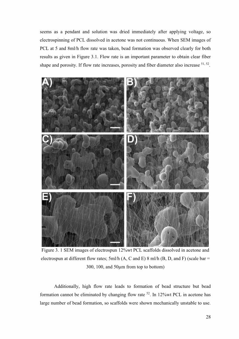
Polycarbonate (PC) membrane inserts are commercially available and commonly
used to trigger cell differentiation and tissue formation in intestinal tissue engineering
studies. For comparison, electrospun polycarbonate as scaffold was investigated as well.
In literature, chloroform, THF and DMF are used to solve polycarbonate, so combinations
of solvents were optimized. First, 14%wt PC in chloroform solution was prepared but
polycarbonate was not dissolved in chloroform homogenously after 24 hours incubation.
Although solution was heated, polycarbonate was not dissolved in chloroform
31
homogenously. Thus, second solvent combination of THF and DMF were utilized.
Firstly, 10%wt PC were prepared with 7:3 solvent ratio of THF:DMF. However enough
viscosity was not obtained for electrospinning. Then, concentration was increased to
15%wt, but this time polymer solution become non-homogenous, and solubilization
problems observed. When 6:4 THF: DMF was tried, homogenous nanofibers were
obtained at 10 and 15%wt PC concentrations as shown in Figure 3.3.
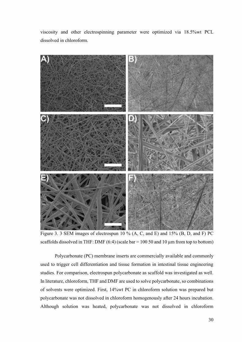
Figure 3. 4 SEM images of electrospun 30% PVDF scaffolds dissolved in DMF: Acetone
(4:1) at different scale 40 (A), 20 (B),10 (C) (D)
PVDF is an excellent biomaterial because of its piezoelectric, mechanical
strength, flexible and easy workable properties 54. It is widely used material in tissue
engineering because of its biocompatible and biodegradable properties 55. As represented
by SEM images, fiber formation was clearly shown in Figure 3.4. During the
electrospinning, solvent types, applied voltage and polymer solution concentration affects
the fiber uniformity and size 56. To obtain PVDF fiber, acetone and DMF were used as
-15
rate of acetone may prevent the irregular fiber formation like beads, while DMF may
provide the fibers to stretch 56. Bead formation was observed because of high electric
field. During the electrospinning, PVDF polymer solution becomes highly charged and it
32
is exposed to electrostatic forces. Repulsion of charges on polymer surface leads to
elongate but viscoelastic force of polymer solution prevents to elongate fibers 56.
Consequently, bead formation was observed in figure 3.4 due to the unstable polymer jet
at high voltage.
3.2. Characterization of PCL, PVDF and PC Scaffolds
Fiber diameter is an important parameter in electrospinning method for adhesion
of the cells onto scaffolds in tissue engineering 57. Fiber diameter of fabricated scaffolds
was analyzed by ImageJ to investigate the scaffold morphology. Electrospun 12%wt PCL
in acetone at 5ml/h and 8ml/h results prove that flow rate affects the fiber diameter, shape
and bead formation. If flow rate increases, fiber diameter also increases. Increases in flow
rate causes the bead formation 52. Two different flow rates which were 5ml/h and 8ml/h
with same concentration were applied to remove bead defects and collector distance and
applied voltage have been adjusted to 150mm and 25kV, but bead structure was not
eliminated. When 18.5%wt PCL scaffold dissolved in chloroform diameter distribution
graph was analyzed, diameter was 6.16 5. High polymer
concentration is resulted in high viscosity and high viscosity of polymer causes to form
thick fiber in diameter 50.
33
Figure 3. 5 SEM images of electrospun 18.5% PCL nanofibers dissolved in chloroform
at different scale 5 1 5 and Fiber Diameter Analysis graph by
ImageJ.
34
Figure 3. 6 SEM images of electrospun 10% (A and C) and 15% (B and D) PC nanofibers
dissolved in THF: DMF (6:4) (scale bar = 50 and from top to bottom) and their
Fiber Diameter Analysis graph by ImageJ
In Figure 3.6, diameter distribution of electrospun PC that has 10 and 15%wt
concentrations were evaluated by ImageJ. The results displayed that electrospun 15%wt
diameter. Concentration increases lead to diameter increases.
The final diameter distribution analysis for electrospun PVDF scaffold is shown
in Figure 3.7. Obtained PVDF scaffolds has approximately 385 nm in diameter. As
mentioned in figure 3.4, acetone evaporation rate faster than DMF. A high voltage causes
35
the unstable polymer jet which induces the larger elongation of fibers and slow
evaporation rate of the solvent, so the smaller fiber diameter was observed.
Figure 3. 7 SEM images of electrospun 30% PVDF nanofibers dissolved in DMF:
Acetone (4:1) at (A), (B), (C) and Fiber Diameter Analysis graph by
ImageJ.
3.2.1 Porosity of PCL, PVDF, and PC Scaffolds
Pore size and area of scaffolds are important parameters for strong interaction of
cells and scaffold. Porosity provide cellular infiltration and tissue ingrowth in electrospun
nanofiber mats58. In addition to these, cell adhesion, migration, proliferation,
morphology, phenotypic expression DNA synthesis, and extracellular matrix (ECM)
composition can be altered by porosity58, 59. Porosity play an important role in diffusion
of nutrients, metabolites, and waste products60. Thus, porosity of electrospun scaffolds
favor cellular adhesion and growth. However, many electrospun scaffolds has small
pores which limit cellular infiltration and tissue ingrowth in scaffold58. Recent studies
show that fiber diameter, pore size and pore area are related with each other. If fiber
36
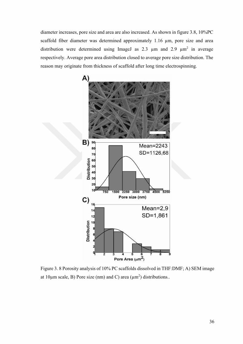
diameter increases, pore size and area are also increased. As shown in figure 3.8, 10%PC
size and area
distribution were determined using ImageJ as 2.3 2 in average
respectively. Average pore area distribution closed to average pore size distribution. The
reason may originate from thickness of scaffold after long time electrospinning.
Figure 3. 8 Porosity analysis of 10% PC scaffolds dissolved in THF:DMF; A) SEM image
2) distributions..

37
Figure 3. 9 Porosity analysis of 18.5% PCL scaffolds dissolved in chloroform; A) SEM
image 2) distributions.
For PCL, the calculated average fiber diameter, pore size and pore are were 6
12 2 respectively as given in Figure 3.9. Square of average pore size was
proportional to average pore area. Electrospun PCL scaffold had larger pore area than
electrospun PC scaffold. Lastly, PVDF fiber diameter analysis showed 385 nm in 2 average in pore area as shown in
figure 3.10. All results suggest that fiber diameter correlates with pore size of electrospun
nanofiber scaffolds. PCL had the largest pore area than electrospun PC and PVDF
38
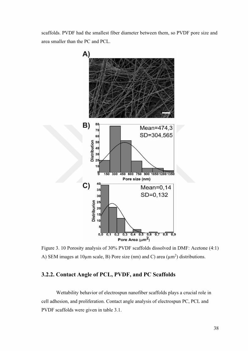
scaffolds. PVDF had the smallest fiber diameter between them, so PVDF pore size and
area smaller than the PC and PCL.
Figure 3. 10 Porosity analysis of 30% PVDF scaffolds dissolved in DMF: Acetone (4:1)
A) SEM images 2) distributions.
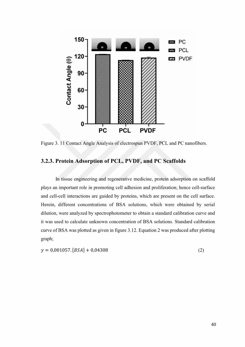
3.2.2. Contact Angle of PCL, PVDF, and PC Scaffolds
Wettability behavior of electrospun nanofiber scaffolds plays a crucial role in
cell adhesion, and proliferation. Contact angle analysis of electrospun PC, PCL and
PVDF scaffolds were given in table 3.1.
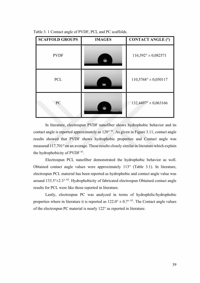
39
Table 3. 1 Contact angle of PVDF, PCL and PC scaffolds.
SCAFFOLD GROUPS IMAGES
PVDF
PCL
PC
In literature, electrospun PVDF nanofiber shows hydrophobic behavior and its
contact angle is reported approximately as 61. As given in Figure 3.11, contact angle
results showed that PVDF shows hydrophobic properties and Contact angle was
measured These results closely similar in literature which explain
the hydrophobicity of PVDF 61.
Electrospun PCL nanofiber demonstrated the hydrophobic behavior as well.
Obtained c (Table 3.1). In literature,
electrospun PCL material has been reported as hydrophobic and contact angle value was
around 62. Hydrophobicity of fabricated electrospun Obtained contact angle
results for PCL were like those reported in literature.
Lastly, electrospun PC was analyzed in terms of hydrophilic/hydrophobic
properties where in literature it is reported as 122.0 63. The Contact angle values
of the electrospun PC material is nearly 122 as reported in literature.
40
Figure 3. 11 Contact Angle Analysis of electrospun PVDF, PCL and PC nanofibers.
3.2.3. Protein Adsorption of PCL, PVDF, and PC Scaffolds
In tissue engineering and regenerative medicine, protein adsorption on scaffold
plays an important role in promoting cell adhesion and proliferation; hence cell-surface
and cell-cell interactions are guided by proteins, which are present on the cell surface.
Herein, different concentrations of BSA solutions, which were obtained by serial
dilution, were analyzed by spectrophotometer to obtain a standard calibration curve and
it was used to calculate unknown concentration of BSA solutions. Standard calibration
curve of BSA was plotted as given in figure 3.12. Equation 2 was produced after plotting
graph;
(2)
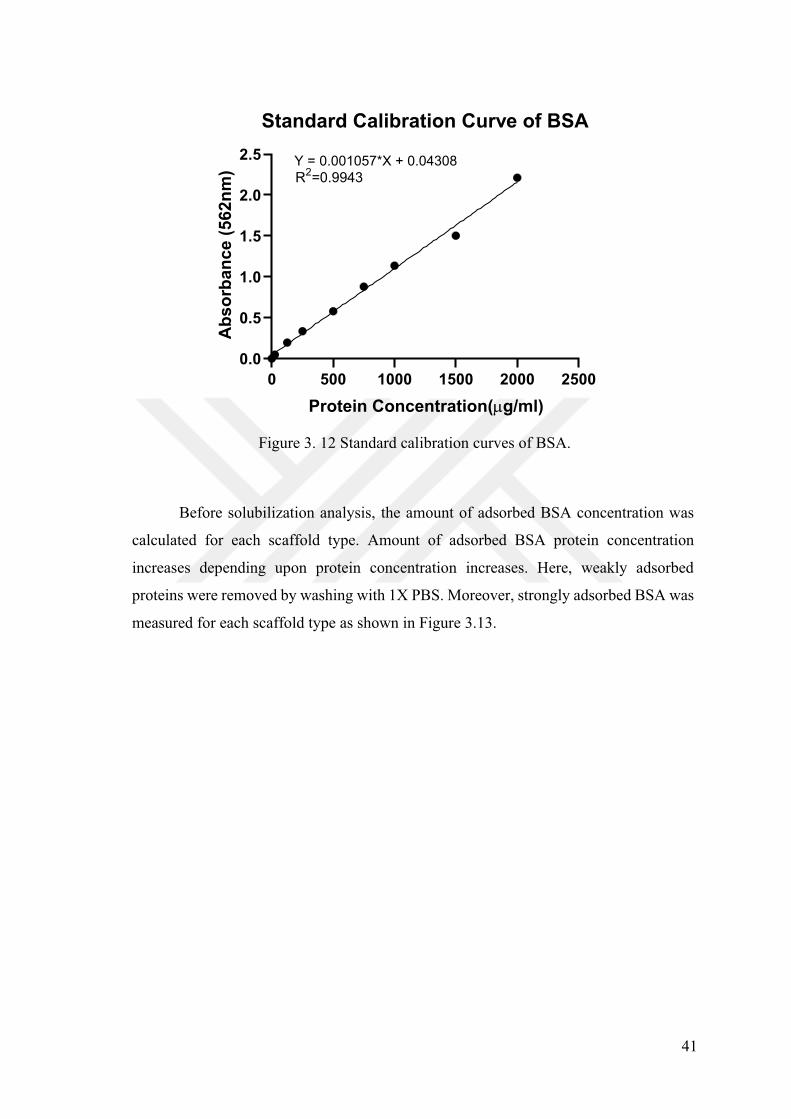
41
Figure 3. 12 Standard calibration curves of BSA.
Before solubilization analysis, the amount of adsorbed BSA concentration was
calculated for each scaffold type. Amount of adsorbed BSA protein concentration
increases depending upon protein concentration increases. Here, weakly adsorbed
proteins were removed by washing with 1X PBS. Moreover, strongly adsorbed BSA was
measured for each scaffold type as shown in Figure 3.13.
0 500 1000 1500 2000 25000.0
0.5
1.0
1.5
2.0
2.5
Standard Calibration Curve of BSA
Protein Concentration( g/ml)
Abs
orba
nce
(562
nm) Y = 0.001057*X + 0.04308
R2=0.9943

42
Figure 3. 13Adsorbed BSA on PC, PCL and PVDF scaffold.
To validate the strong protein adsorption, BSA protein was solubilized in
detergent. 5%w/v of SDS, Tween 20 and TritonX-100 was utilized separately to measure
solubilization of strongly adsorbed protein on scaffolds. As shown in SDS solubilization
results in Figure 3.14, each scaffold reached to equilibrium and saturation after a certain
point where PCL scaffold had the higher amount of adsorbed protein. When SDS is used
for solubilization of BSA that is adsorbed on PC, PCL and PVDF scaffolds, interference
problem is observed during measurements and it limits the amount of measured protein.
Therefore, for further analysis Tween 20 and TritonX-100 were used to solubilize
adsorbed BSA on PC, PCL and PVDF scaffolds.
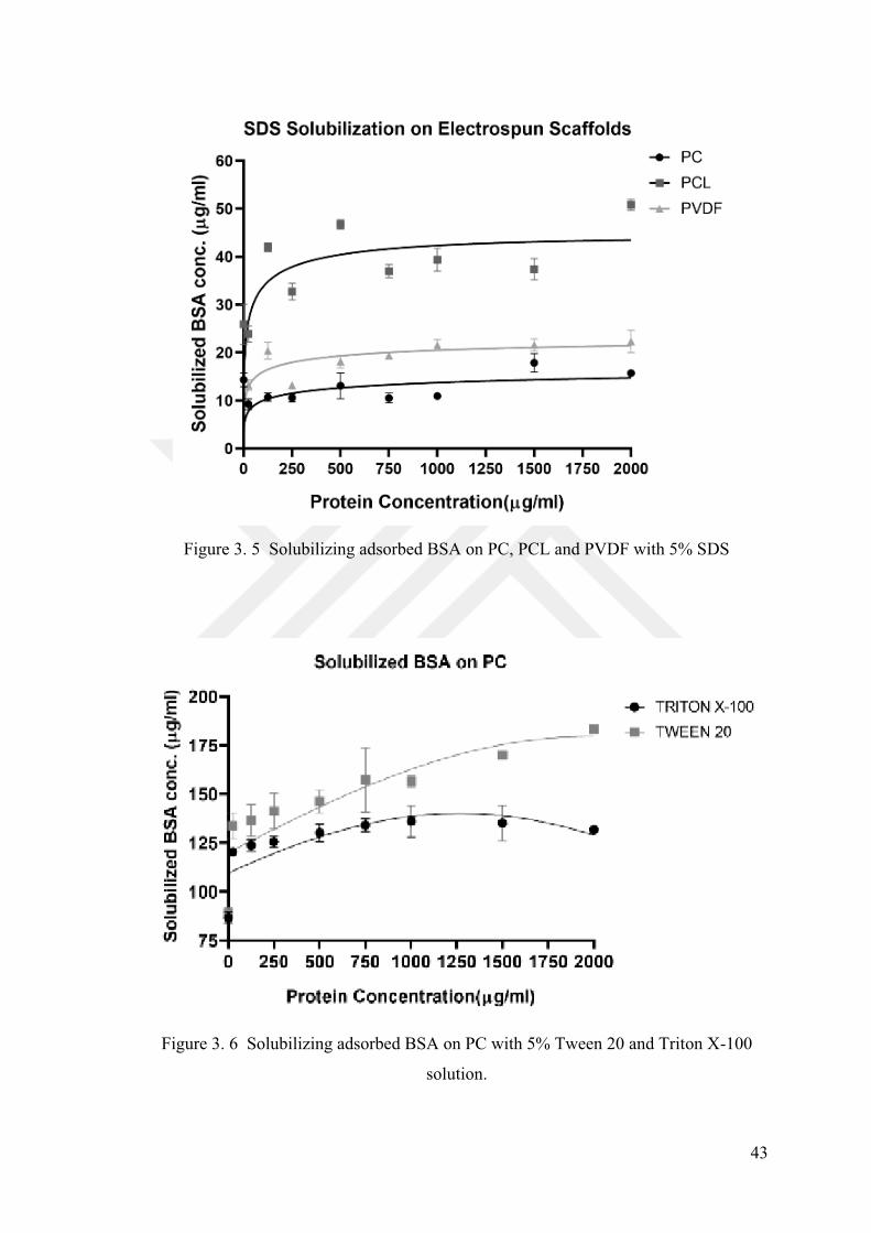
43
Figure 3. 5 Solubilizing adsorbed BSA on PC, PCL and PVDF with 5% SDS
Figure 3. 6 Solubilizing adsorbed BSA on PC with 5% Tween 20 and Triton X-100
solution.
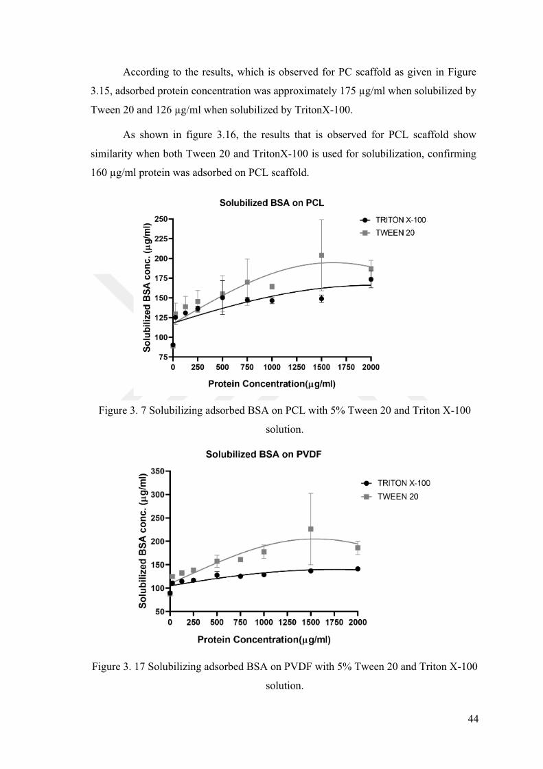
44
According to the results, which is observed for PC scaffold as given in Figure
3.15
Tween 20 and 1 -100.
As shown in figure 3.16, the results that is observed for PCL scaffold show
similarity when both Tween 20 and TritonX-100 is used for solubilization, confirming
adsorbed on PCL scaffold.
Figure 3. 7 Solubilizing adsorbed BSA on PCL with 5% Tween 20 and Triton X-100
solution.
Figure 3. 17 Solubilizing adsorbed BSA on PVDF with 5% Tween 20 and Triton X-100
solution.
45
Lastly PVDF scaffold was analyzed to observe the adsorbed BSA on PVDF,
where 147 was observed for TritonX-100 solubilized samples and 120
was observed for Tween 20 solubilized ones, as shown in figure 3.18.
Results are correlated with each other for PVDF scaffold. As a result of protein
adsorption assay, both TritonX-100 and Tween 20 solubilization exhibit more consistent
results. However, SDS was not suitable for solubilization of proteins on PC, PCL and
PVDF scaffolds. As mention above, protein adsorption assay is crucial to determine
scaffold candidate for cell adhesion and proliferation. Increment of adsorbed protein on
scaffolds means that attachment of target cells to the scaffolds is favorable. Among all
the scaffolds, average adsorbed protein on PCL was slightly higher than others. Adsorbed
protein amount on PVDF scaffolds is lower than on PC scaffold. As a result, it can be
concluded that electrospun PCL scaffold might be the best candidate for cell attachment
and growth.
3.2.4. Hydrolytic and Enzymatic Degradation of PC, PCL, and PVDF
Scaffolds
PC, PCL and PVDF are biocompatible and bioresorbable polymers which have
been studied in biomedical applications to develop tissue scaffolds or nanomaterials for
drug delivery studies64. Hydrolytic degradation is originated from scission of chemical
bonds in polymer backbone via water. Hydrophilic or hydrophobic characteristic of
polymer affects hydrolytic degradation as well as effects of molecular weight,
temperature, intensity of ester groups and degradation media.
Herein, the temperature was kept as (15 weeks)
and degradation analysis of electrospun PC, PCL and PVDF scaffolds. As given in Figure
3.18, PC weight loss (%) was observed after 7 weeks only when lysozyme enzyme is used
but degradation in PBS was observed in 8th week result. Besides PBS and lysozyme, cell
culture medium MEM was also evaluated in terms of degradation effects on electrospun
scaffolds. After 10 weeks, weight loss was significant and around 3%. The highest
degradation rate was obtained from lysozyme at 15-week enzymatic and hydrolytic
degradation experiments for PC. Lysozyme causes 14.2% weight loss in 15th week.
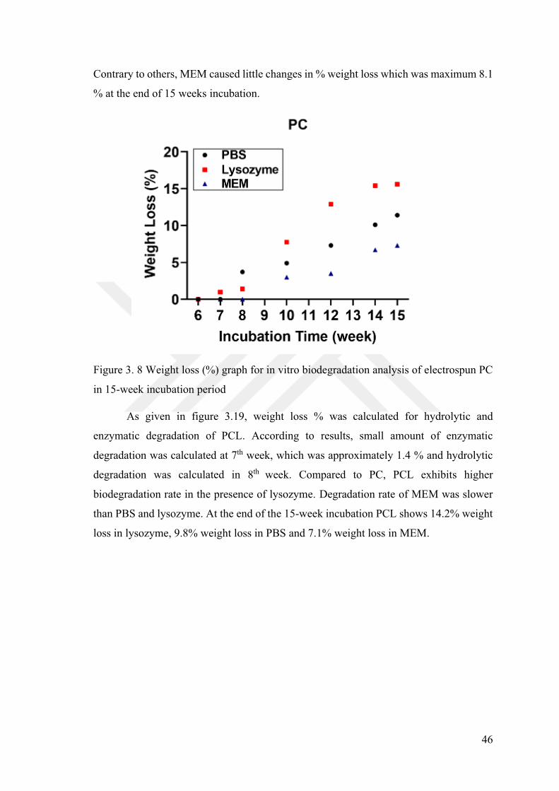
46
Contrary to others, MEM caused little changes in % weight loss which was maximum 8.1
% at the end of 15 weeks incubation.
Figure 3. 8 Weight loss (%) graph for in vitro biodegradation analysis of electrospun PC
in 15-week incubation period
As given in figure 3.19, weight loss % was calculated for hydrolytic and
enzymatic degradation of PCL. According to results, small amount of enzymatic
degradation was calculated at 7th week, which was approximately 1.4 % and hydrolytic
degradation was calculated in 8th week. Compared to PC, PCL exhibits higher
biodegradation rate in the presence of lysozyme. Degradation rate of MEM was slower
than PBS and lysozyme. At the end of the 15-week incubation PCL shows 14.2% weight
loss in lysozyme, 9.8% weight loss in PBS and 7.1% weight loss in MEM.
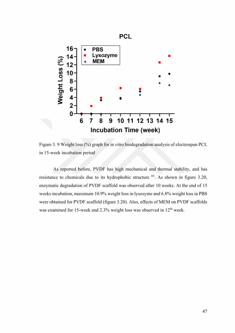
47
Figure 3. 9 Weight loss (%) graph for in vitro biodegradation analysis of electrospun PCL
in 15-week incubation period
As reported before, PVDF has high mechanical and thermal stability, and has
resistance to chemicals due to its hydrophobic structure 65. As shown in figure 3.20,
enzymatic degradation of PVDF scaffold was observed after 10 weeks. At the end of 15
weeks incubation, maximum 10.9% weight loss in lysozyme and 6.8% weight loss in PBS
were obtained for PVDF scaffold (figure 3.20). Also, effects of MEM on PVDF scaffolds
was examined for 15-week and 2.3% weight loss was observed in 12th week.
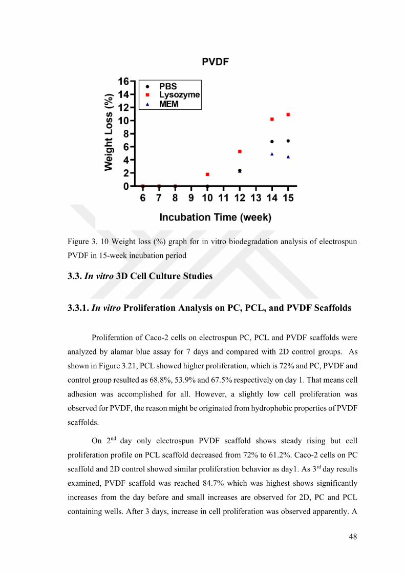
48
Figure 3. 10 Weight loss (%) graph for in vitro biodegradation analysis of electrospun
PVDF in 15-week incubation period
3.3. In vitro 3D Cell Culture Studies
3.3.1. In vitro Proliferation Analysis on PC, PCL, and PVDF Scaffolds
Proliferation of Caco-2 cells on electrospun PC, PCL and PVDF scaffolds were
analyzed by alamar blue assay for 7 days and compared with 2D control groups. As
shown in Figure 3.21, PCL showed higher proliferation, which is 72% and PC, PVDF and
control group resulted as 68.8%, 53.9% and 67.5% respectively on day 1. That means cell
adhesion was accomplished for all. However, a slightly low cell proliferation was
observed for PVDF, the reason might be originated from hydrophobic properties of PVDF
scaffolds.
On 2nd day only electrospun PVDF scaffold shows steady rising but cell
proliferation profile on PCL scaffold decreased from 72% to 61.2%. Caco-2 cells on PC
scaffold and 2D control showed similar proliferation behavior as day1. As 3rd day results
examined, PVDF scaffold was reached 84.7% which was highest shows significantly
increases from the day before and small increases are observed for 2D, PC and PCL
containing wells. After 3 days, increase in cell proliferation was observed apparently. A
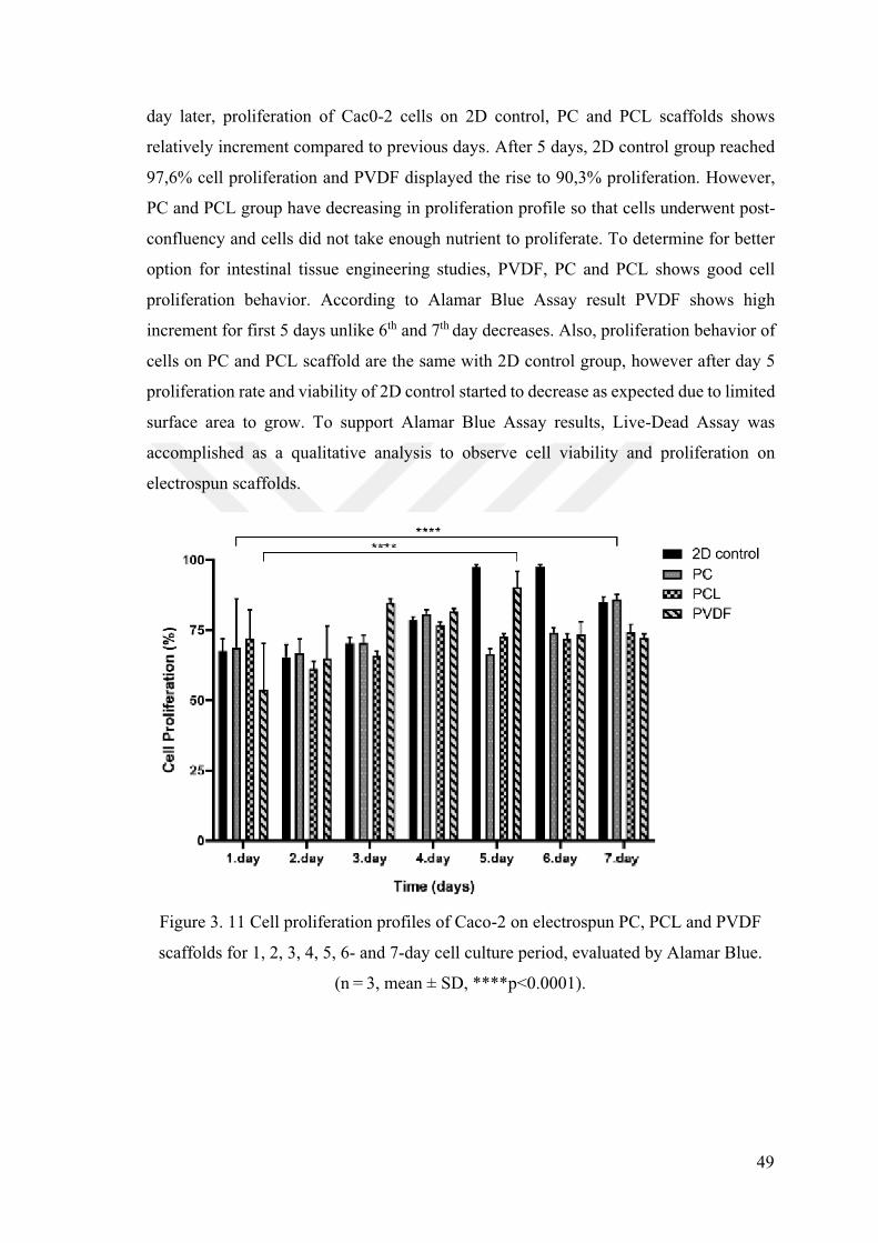
49
day later, proliferation of Cac0-2 cells on 2D control, PC and PCL scaffolds shows
relatively increment compared to previous days. After 5 days, 2D control group reached
97,6% cell proliferation and PVDF displayed the rise to 90,3% proliferation. However,
PC and PCL group have decreasing in proliferation profile so that cells underwent post-
confluency and cells did not take enough nutrient to proliferate. To determine for better
option for intestinal tissue engineering studies, PVDF, PC and PCL shows good cell
proliferation behavior. According to Alamar Blue Assay result PVDF shows high
increment for first 5 days unlike 6th and 7th day decreases. Also, proliferation behavior of
cells on PC and PCL scaffold are the same with 2D control group, however after day 5
proliferation rate and viability of 2D control started to decrease as expected due to limited
surface area to grow. To support Alamar Blue Assay results, Live-Dead Assay was
accomplished as a qualitative analysis to observe cell viability and proliferation on
electrospun scaffolds.
Figure 3. 11 Cell proliferation profiles of Caco-2 on electrospun PC, PCL and PVDF
scaffolds for 1, 2, 3, 4, 5, 6- and 7-day cell culture period, evaluated by Alamar Blue.
, mean SD, ****p<0.0001).
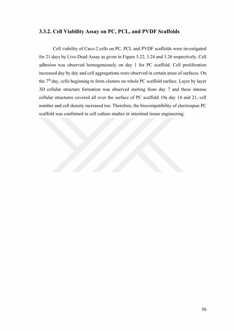
50
3.3.2. Cell Viability Assay on PC, PCL, and PVDF Scaffolds
Cell viability of Caco-2 cells on PC, PCL and PVDF scaffolds were investigated
for 21 days by Live-Dead Assay as given in Figure 3.22, 3.24 and 3.26 respectively. Cell
adhesion was observed homogeneously on day 1 for PC scaffold. Cell proliferation
increased day by day and cell aggregations were observed in certain areas of surfaces. On
the 7th day, cells beginning to form clusters on whole PC scaffold surface. Layer by layer
3D cellular structure formation was observed starting from day 7 and these intense
cellular structures covered all over the surface of PC scaffold. On day 14 and 21, cell
number and cell density increased too. Therefore, the biocompatibility of electrospun PC
scaffold was confirmed in cell culture studies in intestinal tissue engineering.
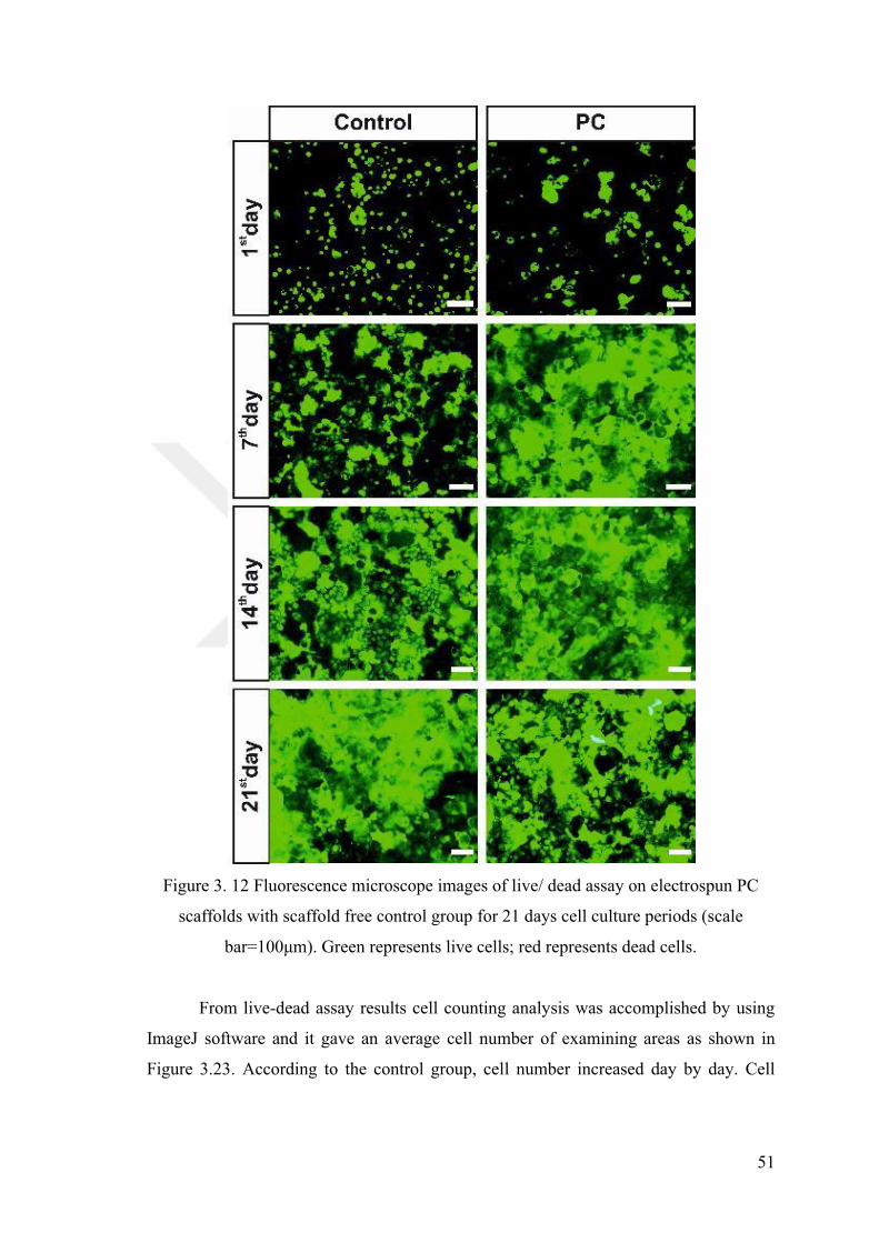
51
Figure 3. 12 Fluorescence microscope images of live/ dead assay on electrospun PC
scaffolds with scaffold free control group for 21 days cell culture periods (scale
From live-dead assay results cell counting analysis was accomplished by using
ImageJ software and it gave an average cell number of examining areas as shown in
Figure 3.23. According to the control group, cell number increased day by day. Cell
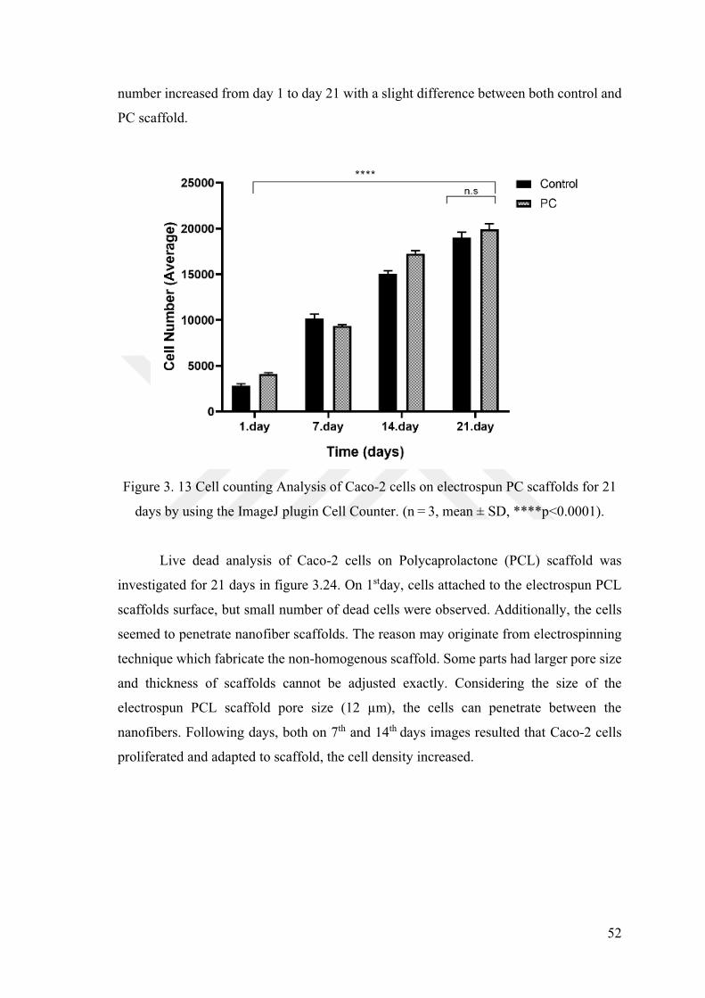
52
number increased from day 1 to day 21 with a slight difference between both control and
PC scaffold.
Figure 3. 13 Cell counting Analysis of Caco-2 cells on electrospun PC scaffolds for 21
days by using the ImageJ plugin Cell Counter. , mean SD, ****p<0.0001).
Live dead analysis of Caco-2 cells on Polycaprolactone (PCL) scaffold was
investigated for 21 days in figure 3.24. On 1stday, cells attached to the electrospun PCL
scaffolds surface, but small number of dead cells were observed. Additionally, the cells
seemed to penetrate nanofiber scaffolds. The reason may originate from electrospinning
technique which fabricate the non-homogenous scaffold. Some parts had larger pore size
and thickness of scaffolds cannot be adjusted exactly. Considering the size of the
electrospun PCL scaffold pore size
nanofibers. Following days, both on 7th and 14th days images resulted that Caco-2 cells
proliferated and adapted to scaffold, the cell density increased.
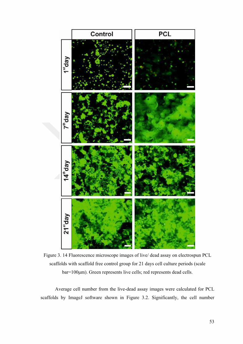
53
Figure 3. 14 Fluorescence microscope images of live/ dead assay on electrospun PCL
scaffolds with scaffold free control group for 21 days cell culture periods (scale
presents dead cells.
Average cell number from the live-dead assay images were calculated for PCL
scaffolds by ImageJ software shown in Figure 3.2. Significantly, the cell number
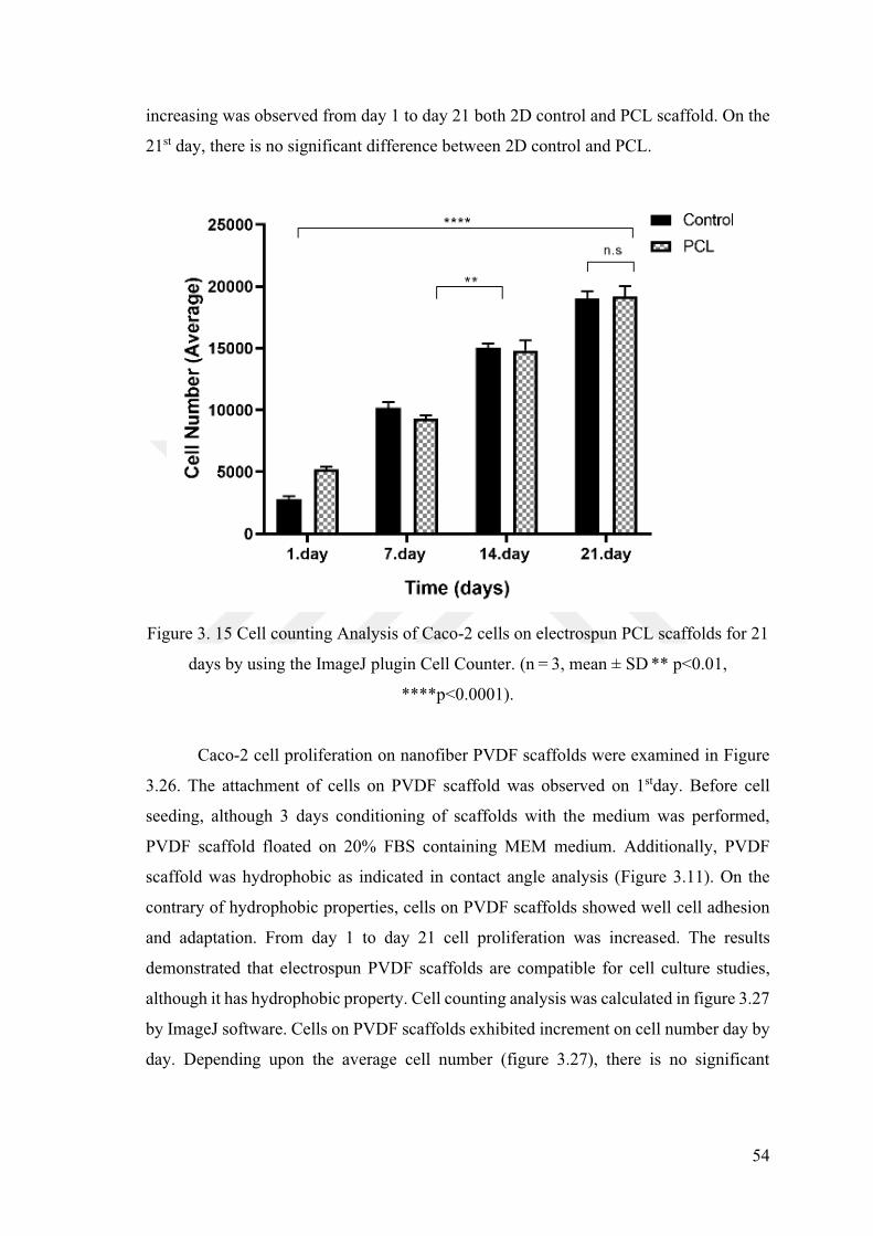
54
increasing was observed from day 1 to day 21 both 2D control and PCL scaffold. On the
21st day, there is no significant difference between 2D control and PCL.
Figure 3. 15 Cell counting Analysis of Caco-2 cells on electrospun PCL scaffolds for 21
days by using the ImageJ plugin Cell Counter. , mean SD ** p<0.01,
****p<0.0001).
Caco-2 cell proliferation on nanofiber PVDF scaffolds were examined in Figure
3.26. The attachment of cells on PVDF scaffold was observed on 1stday. Before cell
seeding, although 3 days conditioning of scaffolds with the medium was performed,
PVDF scaffold floated on 20% FBS containing MEM medium. Additionally, PVDF
scaffold was hydrophobic as indicated in contact angle analysis (Figure 3.11). On the
contrary of hydrophobic properties, cells on PVDF scaffolds showed well cell adhesion
and adaptation. From day 1 to day 21 cell proliferation was increased. The results
demonstrated that electrospun PVDF scaffolds are compatible for cell culture studies,
although it has hydrophobic property. Cell counting analysis was calculated in figure 3.27
by ImageJ software. Cells on PVDF scaffolds exhibited increment on cell number day by
day. Depending upon the average cell number (figure 3.27), there is no significant
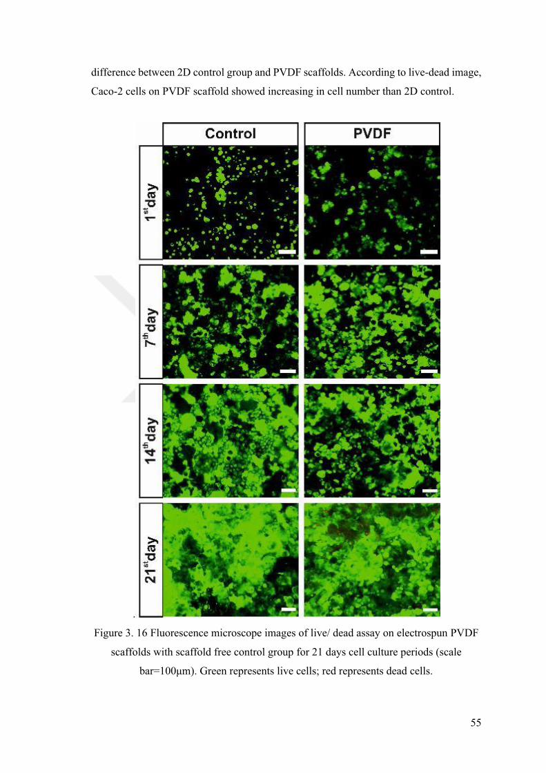
55
difference between 2D control group and PVDF scaffolds. According to live-dead image,
Caco-2 cells on PVDF scaffold showed increasing in cell number than 2D control.
.
Figure 3. 16 Fluorescence microscope images of live/ dead assay on electrospun PVDF
scaffolds with scaffold free control group for 21 days cell culture periods (scale
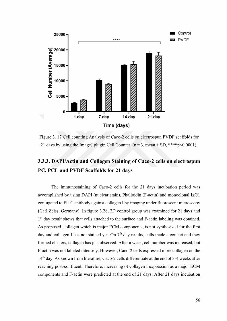
56
Figure 3. 17 Cell counting Analysis of Caco-2 cells on electrospun PVDF scaffolds for
21 days by using the ImageJ plugin Cell Counter. , mean SD, ****p<0.0001).
3.3.3. DAPI/Actin and Collagen Staining of Caco-2 cells on electrospun
PC, PCL and PVDF Scaffolds for 21 days
The immunostaining of Caco-2 cells for the 21 days incubation period was
accomplished by using DAPI (nuclear stain), Phalloidin (F-actin) and monoclonal IgG1
conjugated to FITC antibody against collagen I by imaging under fluorescent microscopy
(Carl Zeiss, Germany). In figure 3.28, 2D control group was examined for 21 days and
1st day result shows that cells attached to the surface and F-actin labeling was obtained.
As proposed, collagen which is major ECM components, is not synthesized for the first
day and collagen I has not stained yet. On 7th day results, cells made a contact and they
formed clusters, collagen has just observed. After a week, cell number was increased, but
F-actin was not labeled intensely. However, Caco-2 cells expressed more collagen on the
14th day. As known from literature, Caco-2 cells differentiate at the end of 3-4 weeks after
reaching post-confluent. Therefore, increasing of collagen I expression as a major ECM
components and F-actin were predicted at the end of 21 days. After 21 days incubation
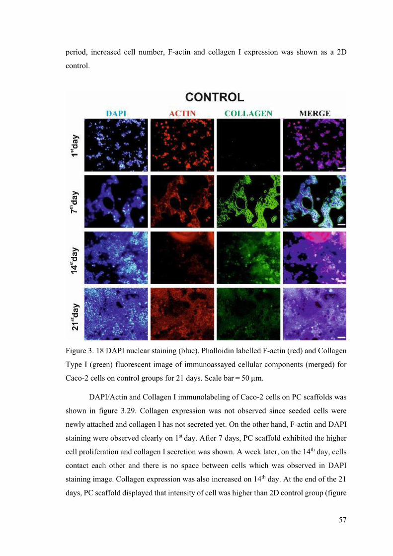
57
period, increased cell number, F-actin and collagen I expression was shown as a 2D
control.
Figure 3. 18 DAPI nuclear staining (blue), Phalloidin labelled F-actin (red) and Collagen
Type I (green) fluorescent image of immunoassayed cellular components (merged) for
Caco-2 cells on control groups for 21 days.
DAPI/Actin and Collagen I immunolabeling of Caco-2 cells on PC scaffolds was
shown in figure 3.29. Collagen expression was not observed since seeded cells were
newly attached and collagen I has not secreted yet. On the other hand, F-actin and DAPI
staining were observed clearly on 1st day. After 7 days, PC scaffold exhibited the higher
cell proliferation and collagen I secretion was shown. A week later, on the 14th day, cells
contact each other and there is no space between cells which was observed in DAPI
staining image. Collagen expression was also increased on 14th day. At the end of the 21
days, PC scaffold displayed that intensity of cell was higher than 2D control group (figure
58
3.29). Intense F-actin and collagen labeling was obtained. Thus, electrospun PC scaffold
provided good microenvironment to Caco-2 cells, so they proliferate and secrete own
ECM components.
Figure 3. 19 DAPI nuclear staining (blue), Phalloidin labelled F-actin (red) and Collagen
Type I (green) fluorescent image of immunoassayed cellular components (merged) for
Caco-2 cells on electrospun PC scaffolds for 21 days
DAPI/Actin and Collagen I Immunostaining of Caco-2 cells seeded on PCL
scaffold results were shown in Figure 3.30. On the 1st day, interestingly, small amount of
collagen was observed. F-actin labeling was observed blurred. The imaging problem can
be originated from 3D scaffold structure and as explain previously, PCL scaffold has the
larger pore size than other scaffolds and cells attached into nanofibers, so the focusing
problem happened. After a week, PCL shows increasing cell number, but we observed
the nonspecific fluorescent labeling. Actin and collagen labeling were stained at the same
region, but DAPI staining was independent from actin and collagen overlaid regions. On

59
the 14th day, cell number increasing was shown clearly, and collagen intensity was higher
than on the 7th day. After 21 days, intensity of collagen, F-actin and DAPI were increased.
Figure 3. 20 DAPI nuclear staining (blue), Phalloidin labelled F-actin (red) and Collagen
Type I (green) fluorescent image of immunoassayed cellular components (merged) for
Caco-2 cells on electrospun PCL scaffolds for 21 days
In figure 3.31, DAPI/Actin and Collagen I immunostaining of Caco-2 cells on
PVDF scaffolds were exhibited. On the 1st day, cells attached onto scaffold and there is
no collagen expression. On the 7th day, results displayed that cell number increased and
collagen I secretion was observed. A week later, all over the scaffold surface was covered
by cells. Collagen I and F-actin fluorescent intensity increased. On the 21st day, collagen
and F-actin expression were increased highly, and there is no space on scaffolds was
observed.
60
Figure 3. 21 DAPI nuclear staining (blue), Phalloidin labelled F-actin (red) and Collagen
Type I (green) fluorescent image of immunoassayed cellular components (merged) for
Caco-2 cells on electrospun PVDF scaffolds for 21 days
In conclusion, Caco-2 cells on electrospun PC, PCL and PVDF scaffolds
displayed that cell number and communication were increased week by week. Cells
adapted on fabricated scaffolds and they can express their own ECM component to make
tissue formation.
3.3.5. Designation of Microdevice and Cell Seeding on Microfabricated
Transwell Insert
Microdevice fabrication has key role in tissue engineering application to make
exact mimicking of tissue structure and function. According to studies, Transwell inserts
are commonly used in intestinal tissue engineering strategies to simulate cellular
61
interaction and cross talking of different cells as real tissue. In this case, new Transwell
insert was designed by using electrospun PC, PCL and PVDF scaffolds as a membrane
where cell was cultured on it. In order to combine commercial Transwell without
membrane with fabricated electrospun PC, PCL and PVDF scaffolds, different techniques
were tried. Initially, we tried to stick the scaffolds at the bottom side of Transwell. As
well known, non-toxic materials should be used to insert membrane in Transwell because
they are going to use in cell culture study. Any toxic material can cause the cell death,
which is undesired result. Therefore, solvents for each polymer was accomplished to stick
PC, PCL and PVDF scaffolds. To prepare the solutions of PC, PCL and PVDF
respectively diluted DMF: THF, chloroform and acetone were used. Diluted solvents
were utilized for each setup to prevent damage on Transwells. In very diluted conditions,
scaffolds did not stick strongly to bottom part of Transwells. Hence, to design electrospun
scaffold Transwell insert, 3.4 mm thick PMMA circle were cut via the laser cutter
machine to place into 12- well plate insert bottom end. Fabrication steps are given in
Figure 3.32, 3.33 and 3.34, Initial step was squeezing of first 3.4 mm thick PMMA circle
into empty insert which is represented in the 3rd image of figure 3.32. Then, 13 mm in
diameter PC, PCL and PVDF scaffolds were cut separately and they were placed onto
PMMA circle as indicated in 4th, 5th and 6th image of Figure 3.33. In order to make tight
scaffold contained transwell insert, other PMMA circle was placed on the scaffold as
shown in 7th, 8th and 9th image of Figure 3.34. Finally, mechanical compaction was
applied for each scaffold containing insert. To test leakage, 1X PBS was loaded in
transwells and there was no leakage from Transwell insert. Thus, designed cell culture
well inserts can be used in cell culture study.
Figure 3. 22 Designation of Transwell Insert by using electrospun PC, PCL and PVDF
scaffolds step by step.
62
Figure 3. 23(Cont.)
Figure 3. 24 (Cont)
In this step, Caco-2 cell seeded in Transwell inserts as shown in Figure 3.35. In
the electrospun PCL membrane Transwell, filtration of medium was observed, but in PC
and PVDF scaffold containing Transwell medium was not filtrated into the lower
compartment. The reason of this was originated from pore sizes of fabricated scaffolds as
resulted in Figure 3.11, PCL has a
Transwell in
Therefore, the medium was filtrated into the lower compartment from upper
compartment.
Figure 3. 25. Caco-2 cell seeding on designed PC, PCL and PVDF membrane Transwell
insert.
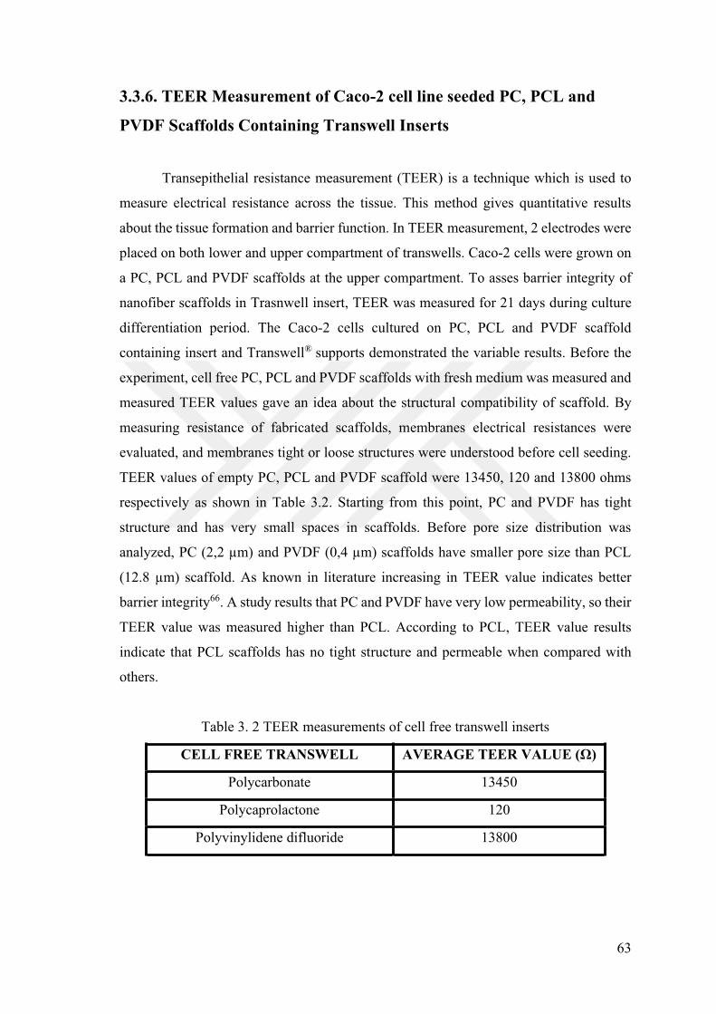
63
3.3.6. TEER Measurement of Caco-2 cell line seeded PC, PCL and
PVDF Scaffolds Containing Transwell Inserts
Transepithelial resistance measurement (TEER) is a technique which is used to
measure electrical resistance across the tissue. This method gives quantitative results
about the tissue formation and barrier function. In TEER measurement, 2 electrodes were
placed on both lower and upper compartment of transwells. Caco-2 cells were grown on
a PC, PCL and PVDF scaffolds at the upper compartment. To asses barrier integrity of
nanofiber scaffolds in Trasnwell insert, TEER was measured for 21 days during culture
differentiation period. The Caco-2 cells cultured on PC, PCL and PVDF scaffold
containing insert and Transwell supports demonstrated the variable results. Before the
experiment, cell free PC, PCL and PVDF scaffolds with fresh medium was measured and
measured TEER values gave an idea about the structural compatibility of scaffold. By
measuring resistance of fabricated scaffolds, membranes electrical resistances were
evaluated, and membranes tight or loose structures were understood before cell seeding.
TEER values of empty PC, PCL and PVDF scaffold were 13450, 120 and 13800 ohms
respectively as shown in Table 3.2. Starting from this point, PC and PVDF has tight
structure and has very small spaces in scaffolds. Before pore size distribution was
TEER value indicates better
barrier integrity66. A study results that PC and PVDF have very low permeability, so their
TEER value was measured higher than PCL. According to PCL, TEER value results
indicate that PCL scaffolds has no tight structure and permeable when compared with
others.
Table 3. 2 TEER measurements of cell free transwell inserts
CELL FREE TRANSWELL AVERAGE TEER VALUE
Polycarbonate 13450
Polycaprolactone 120
Polyvinylidene difluoride 13800
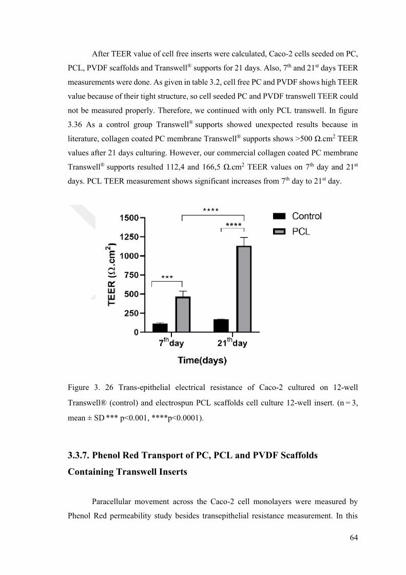
64
After TEER value of cell free inserts were calculated, Caco-2 cells seeded on PC,
PCL, PVDF scaffolds and Transwell supports for 21 days. Also, 7th and 21st days TEER
measurements were done. As given in table 3.2, cell free PC and PVDF shows high TEER
value because of their tight structure, so cell seeded PC and PVDF transwell TEER could
not be measured properly. Therefore, we continued with only PCL transwell. In figure
3.36 As a control group Transwell supports showed unexpected results because in
literature, collagen coated PC membrane Transwell supports shows >500 .cm2 TEER
values after 21 days culturing. However, our commercial collagen coated PC membrane
Transwell supports resulted 112,4 and 166,5 .cm2 TEER values on 7th day and 21st
days. PCL TEER measurement shows significant increases from 7th day to 21st day.
Figure 3. 26 Trans-epithelial electrical resistance of Caco-2 cultured on 12-well
(control) and electrospun PCL scaffolds cell culture 12-well insert. ,
mean SD *** p<0.001, ****p<0.0001).
3.3.7. Phenol Red Transport of PC, PCL and PVDF Scaffolds
Containing Transwell Inserts
Paracellular movement across the Caco-2 cell monolayers were measured by
Phenol Red permeability study besides transepithelial resistance measurement. In this
65
step, we illustrate that % transport of phenol red from the apical to basal chamber was
examined by adding Phenol red to the apical chamber to determine its permeability into
the basal chamber for 24 h of exposure. As given in Figure 3.37, % transport of
electrospun PC, PCL and PVDF scaffolds were calculated after absorbance was measured
at 560nm. According to PCL results, % permeability was significantly different from
others. During the 8. hour PC, PCL and PVDF showed almost similar phenol red %
transport. PCL showed increasing in transport % after 8 hours. As known in Figure 3.8
, in Figure 3.9 PCL has 0
others PCL can filtrate higher amount of phenol red comparison with PC and PVDF.
PVDF has the smallest pore size among the others along with hydrophobic properties. PC
and PVDF showed maximum % 12 and 9 Phenol red transport across the scaffolds
respectively at the end of 24 hours exposure. However, in PCL scaffold % 50 Phenol red
transport was calculated at the end of the 24 hours incubation period. In this case we
confirm that PC and PVDF scaffolds have tighter structure than PCL scaffold, so %
phenol red transport was higher in PCL when compared with others.
Figure 3. 27 % Phenol red transport measurements across the designed cell free PC, PCL
and PVDF scaffold containing Transwell insert to determine leakage for 24 hours
exposure time.
66
As mentioned before, Phenol red permeability assay is used to determine barrier
integrity of Caco-2 cell line with TEER measurement after 21 days culture period. In this
part, Transwell support was used as a control group and Caco-2 cells were exposed to
calculated. In figure 3.38, % permeability of Phenol red was analyzed after 21 days
culturing period. As known from literature, Caco-2 cells have differentiation ability after
3-4 weeks cell culture period. When Caco-2 cells became confluent, cells begin to form
tissue. Therefore, these barrier like formation partially prevent the leakage of substance
from apical compartment to basal compartment. After 21 days, we expected that %
permeability of Phenol Red can be decreased when compared with cell free PC, PCL and
PVDF scaffolds containing Trasnwell inserts. According to PC results, % permeability of
Caco-2 cell cultured insert shows %18 phenol red transport at the end of the 24 hours.
However, cell free PC Transwell insert showed the % 12 phenol red transport. Normally,
we expected that % phenol red transport decreased after 21 days culturing period. The
reason may be originated from conditioning of scaffolds before the experiment and PC
days. The final reason is that cells grown on PC scaffolds, but they cannot be formed
tissue. When PCL results were analyzed, % permeability of PCL scaffolds was decreased
from %50 to %15 which was serious decreasing. The result suggests that on PCL
scaffolds Caco-2 cells made interaction with each other. Then, they formed barrier, so %
Phenol red transport was decreased. On the other hand, cells cultured on PCL scaffold
Transwell insert showed increasing TEER value from 7th day to 21st day as given in Figure
3.38. Hence, PCL can be better candidate to use in Transwell design and intestinal tissue
engineering applications. The final scaffold was PVDF. It showed irregular
increase/decrease. Cell free PVDF scaffolds % phenol red permeability was % 9 and cell
cultured PVDF scaffold exhibited %15 phenol red transport at the end of 24 hours. When
PVDF result was analyzed, phenol red transport across the scaffold were restricted which
was caused from tight structure of PVDF scaffold. Even after 21 days, PVDF scaffold did
not get wet. If TEER measurement with % phenol red permeability was combined, TEER
measurements emonstrate meaningful values and % permeability experiment
did t give meaningful results too. As an interference, PVDF is not proper for intestinal
tissue engineering application because we cannot show the cell growing and measure
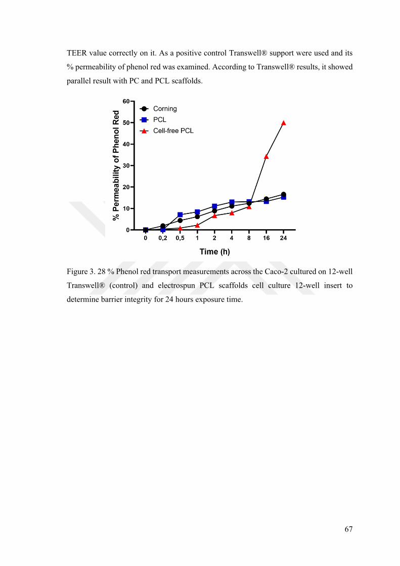
67
TEER value correctly on it. As a positive control support were used and its
% permeability of phenol red was examined. According to results, it showed
parallel result with PC and PCL scaffolds.
Figure 3. 28 % Phenol red transport measurements across the Caco-2 cultured on 12-well
(control) and electrospun PCL scaffolds cell culture 12-well insert to
determine barrier integrity for 24 hours exposure time.
68
CHAPTER 4
CONCLUSION
In this thesis study, PC, PCL and PVDF cell culture well inserts were designed to
mimic 3D human intestinal microstructure. Initially, the characterization of PC, PCL and
PVDF scaffolds which were fabricated by electrospinning method were examined by
SEM image analysis, diameter distribution, pore size and pore area distribution analysis,
contact angle, and protein adsorption assay. After characterization of electrospun
scaffolds, Caco-2 cell was cultured on each of them to understand how compatible they
with colorectal cancer cells are. By the way Live-Dead and Alamar Blue assay were done
for 7 days to determine % cell viability and results elicited that scaffolds were compatible
with Caco-2 cells, so each scaffold was confirmed that they can be integrated into cell
culture well insert. The integration of electrospun PC, PCL and PVDF scaffolds with well
insert was provided by sandwiching of scaffolds between two PMMA circle via
mechanical compaction. As known from the literature, Caco-2 cells were differentiated
after 3-4 weeks culturing and they form intestinal barrier. To understand the functionality
of formed intestinal barrier on designed PC, PCL and PVDF cell culture 12-well insert,
transepithelial electrical resistance and phenol red permeability were tested. Finally,
among 3 different scaffolds, PCL cell culture well insert was selected as a better candidate
for cell culture well insert design.
In conclusion, we clarified that PCL could be used to design cell culture well
insert and to mimic human intestinal system functionally as alternative against the
commercial support.
69
REFERENCES
1. Berthiaume, F., Maguire, T.J., and Yarmush, M.L, Tissue engineering and
regenerative medicine: History, progress, and challenges. Biomolecular Engineering
2011, 2, 403-430.
2. Langer, R. a. V., J.P., Tissue Engineering. Science 1993, 260, 920-926.
3. Randall McClelland, R. D., Lola M.Reid, Bernard Palsson, Jeffery M.Macdonald,
Introduction to Biomedical Engineering. Second ed.; Elsevier 2005.
4. S G Kumbar, R. J., S P Nukavarapu and C T Laurencin, Electrospun nanofiber
scaffolds: engineering soft tissues. Biomedical Materials 2008, 3.
5. James Velema, D. K., Biopolymer-Based Biomaterials as Scaffolds for Tissue
Engineering. Adv Biochem Engin/Biotechnol 2006, 102, 187-238.
6. Kanetkar, N. S.; Ekenseair, A. K., Scaffolds for intestinal tissue engineering. In
Handbook of Tissue Engineering Scaffolds, Elsevier, 2019; Vol. 2, pp 593-632.
7.
-Current Status. American Chemical
Society 2006, 7, 2701-2709.
8. Hodde, J., Review: naturally occurring scaffolds for soft tissue repair and
regeneration. Tissue Eng. 2002, 8, 295-308.
9. Volk, N.; Lacy, B., Anatomy and Physiology of the Small Bowel. Gastrointest
Endosc Clin N Am 2017, 27 (1), 1-13.
10. Mahadevan, V., Anatomy of the small intestine. Surgery 2017, 35, 407-412.
11. Ovesen, L.; Bendtsen, F.; Tage-Jensen, U.; Pedersen, N. T.; Gram, B. R.; Rune,
S. J., Intraluminal pH in the stomach, duodenum, and proximal jejunum in normal
subjects and patients with exocrine pancreatic insufficiency. Gastroenterology 1986, 90
(4), 958-62.
12. Campbell, I., The mouth, stomach and intestines. Anaesth Intensive Care Med
2012, 13, 56-58.
13. Moughan, P. J., Protein: Digestion, Absorption and Metabolism. Elsevier Ltd.
2016.
14. N.G. MacFarlane, Digestion and absorption. Anaesth Intensive Care Med 2018.
15. Britannica, T. E. o. E., Villus. Encyclopaedia Britannica: 2020.
70
16. Steven N. Steinway, J. S., Bon-Kyoung Koo, Delphine Delacour and Deok-Ho
Kim, Human Microphysiological Models of Intestinal Tissue and Gut Microbiome.
Frontiers in Bioengineering and Biotechnology 2020, 8, 725.
17. Rao N. Jaladanki, J.-Y. W., Regulation of gastrointestinal mucosal growth.
Colloquium Series on Integrated Systems Physiology: From Molecule to Function 2011,
114.
18. Shroyer, N. F.; Kocoshis, S. A., Anatomy and physiology of the small and large
intestines. Elsevier 2011, 324-336.
19. C. T.; Draget, K. I., Dynamic responses in small intestinal mucus:
relevance for the maintenance of an intact barrier. Eur J Pharm Biopharm 2015, 95, 144.
20. Barker, N. V. E., J.H. Kuipers, J., Identification of stem cells in small intestine
and colon by marker gene Lgr5. Nature 2007, 449, 1003.
21. Clevers, H. C.; Bevins, C. L., Paneth cells: maestros of the small intestinal crypts.
Annu Rev Physiol 2013, 75, 289.
22. Simon-
basement membrane as a modulator of intestinal epithelial-mesenchymal interactions.
Prog Mol Biol Transl Sci 2010, 96, 175.
23. V. L. Kolachala, R. B., L. Wang, Epithelial-derived fibronectin expression,
signaling, and function in intestinal inflammation. The Journal of Biological Chemistry
2007, 282, 32965 32973.
24. Beaulieu, I. C. T. a. J. F., Interactions between laminin and epithelial cells in
intestinal health and disease. Expert Reviews in Molecular Medicine 2001, 3, 1-18.
25. Laween Meran, A. B., and Vivian S. W. Li, Intestinal Stem Cell Niche: The
Extracellular Matrix and Cellular Components. Stem Cells International 2017, 11.
26. J. P. Hodde, S. F. B., A. O. Brightman, and S. L. Voytik-Harbin,
Glycosaminoglycan content of small intestinal submucosa: a bioscaffold for tissue
replacement. Tissue Engineering 1996, 2, 209-217.
27. Giobbe, G. G., Crowley, C., Luni, C., Campinoti, S., Khedr, M., Kretzschmar, K.,
et al. , Extracellular matrix hydrogel derived from decellularized tissues enables
endodermal organoid culture. Nature Communication 2019, 10, 5658.
28. Griffith, L. G., Emerging design principles in biomaterials and scaffolds for tissue
engineering. Ann N Y Acad Sci 2002, 961, 83-95.
71
29. Ahluwalia, J. C. a. A., Advances and Current Challenges in Intestinal in vitro
Model Engineering: A Digest. Frontiers in Bioengineering and Biotechnology 2019, 7,
144.
30. Dosh RH, J.-M. N., Sammon C, Le Maitre CL., Tissue engineering laboratory
models of the small intestine. Tissue Eng 2018, 24, 98-111.
31. Yamashita, S., Konishi, K., Yamazaki, Y., Taki, Y., Sakane, T., Sezaki, H. and
Furuyama, Y., New and better protocols for a short term Caco-2 cell culture system. J.
Pharm. Sci. 2002, 91.
32. Shah, P., Jogani, V., Bagchi, T. and Misra, A., Role of Caco-2 Cell Monolayers
in Prediction of Intestinal Drug Absorption Biotechnol. Prog. 2006, 22.
33. Chen, X. M., Elisia, I. and Kitts, D. D., Defining conditions for the co-culture of
Caco-2 and HT29-MTX cells using Taguchi design. J. Pharmacol. Toxicol. Methods,
2010., 61, .
34. Kim, H. J., Huh, D., Hamilton, G. and Ingber, D. E., Human gut-on-a-chip
inhabited by microbial flora that experiences intestinal peristalsis-like motions and flow.
Lab Chip 2012, 12.
35. Cait M. Costello, J. H., Shahab Shaffiey, Jiajie Yu, Nina K. Jain, David Hackam,
and John C. March, Synthetic Small Intestinal Scaffolds for Improved Studies of
Intestinal Differentiation. Biotechnol Bioeng 2014, 111.
36. Chen X, Z. J., Gregersen H, The villi contribute to the mechanics in the guinea
pig small intestine. J Biomech. 2008, 41.
37. Raghavan, K. N. B. a. S., Intestinal tissue engineering: current concepts and future
vision of regenerative medicine in the gut. Neurogastroenterol. Motility 2012, 24, 7-19.
38. Jennifer L. West, J. A. H., Bioactive Polymers. In Synthetic Biodegradable
Polymer Scaffolds, Anthony Atala and David Mooney, R. L. J. P. V., Ed. 1997; pp 83-
95.
39. Dohui Kim, S. E., Sang Min Park, Hyeonjun Hong & Dong Sung Kim, A collagen
gel-coated, aligned nanofiber membrane for enhanced endothelial barrier function.
Scientific Reports 2019, 9.
40. Ziyad Jabaji, G. J. B., Hassan A. Khalil, Connie M. Sears, Nan Ye Lei, Michael
Lewis, Matthi
an Extracellular Matrix for the In Vitro Growth of Human Small Intestinal Epithelium.
PLoS One 2014, 9.
72
41. Lin Wang, S. K. M., Gilda A. Barabino, Rebecca L. Carrier, Synergic effects of
crypt-like topography and ECM proteins on intestinal cell behavior in collagen based
membranes. Biomaterials 2010, 31, 7586-7598.
42. Costello, C. M.; Hongpeng, J.; Shaffiey, S.; Yu, J.; Jain, N. K.; Hackam, D.;
March, J. C., Synthetic small intestinal scaffolds for improved studies of intestinal
differentiation. Biotechnol Bioeng 2014, 111 (6), 1222-32.
43. Sung, J. H.; Yu, J.; Luo, D.; Shuler, M. L.; March, J. C., Microscale 3-D hydrogel
scaffold for biomimetic gastrointestinal (GI) tract model. Lab Chip 2011, 11 (3), 389-92.
44. Yu, J.; Peng, S.; Luo, D.; March, J. C., In vitro 3D human small intestinal villous
model for drug permeability determination. Biotechnol Bioeng 2012, 109 (9), 2173-8.
45. Leonard, F., Collnot, E.-M., and Lehr, C.-M., A 3-dimensional co-culture of
enterocytes, macrophages and dendritic cells to model the inflamed intestinal mucosa in
vitro. Mol Pharm 2010, 7.
46. Sarah A. Hewes, R. L. W., Mary K. Estes, Noah F. Shroyer, Sarah E. Blutt, and
K. Jane Grande-Allen,, In Vitro Models of the Small Intestine: Engineering Challenges
and Engineering Solutions. Tissue Eng 2020, 26.
47. Wang, Y.; Gunasekara, D. B.; Reed, M. I.; DiSalvo, M.; Bultman, S. J.; Sims,
C. E.; Magness, S. T.; Allbritton, N. L., A microengineered collagen scaffold for
generating a polarized crypt-villus architecture of human small intestinal epithelium.
Biomaterials 2017, 128, 44-55.
48. Wang, Y.; Ahmad, A. A.; Sims, C. E.; Magness, S. T.; Allbritton, N. L., In vitro
generation of colonic epithelium from primary cells guided by microstructures. Lab Chip
2014, 14 (9), 1622-31.
49. Shim, K. Y.; Lee, D.; Han, J.; Nguyen, N. T.; Park, S.; Sung, J. H., Microfluidic
gut-on-a-chip with three-dimensional villi structure. Biomed Microdevices 2017, 19 (2),
37.
50. Hyung Hwan Kim, M. J. K., Su Jung Ryu, Chang Seok Ki, and Young Hwan Park,
Effect of Fiber Diameter on Surface Morphology, Mechanical Property, and Cell
-caprolactone) Mat. Fibers and Polymers 2016, 17, 1033-
1042.
51. S. Megelski, J. S. S., D. B. Chase, and J. F. Rabolt, Microa nd nanostructured
surface morphology on electrospun polymer fibers. Macromolecules. Macromolecules
2002, 35.
73
52. Vahid Shabafrooz, M. M., Daryoosh Vashaee, and Lobat Tayebi, Electrospun
Nanofibers: From Filtration Membranes to Highly Specialized Tissue Engineering
Scaffolds. Journal of Nanoscience and Nanotechnology 2014, 14, 522-534.
53. A. L. Szentivanyi, H. Z., H. Menzel, and B. Glasmacher,, A review of
developments in electrospinning technology: New opportunities for the design of
artificial tissue structures. Int. J. Artif. Organs. 2011, 34.
54. Federico Fabriani, K. C. C., Iucci Giovanna and Giulia Lanzara, Characterization
of Electrospun PVDF Fibres for Sensing and Actuation. Proceedings 2018, 2, 501.
55. M. H. Alaaeddin, S. M. S., M.Y.M Zuhri, E.S Zainudin, Faris M. AL- Oqla,
Polyvinyl fluoride (PVF); Its Properties, Applications, and Manufacturing Prospects.
Materials Science and Engineering 2019, 538.
56. Sita M Damaraju, S. W., Michael Jaffe and Treena Livingston Arinzeh, Structural
changes in PVDF fibers due to electrospinning and its effect on biological function.
Biomedical Materials 2013, 8, 11.
57. Ming Chen, P. K. P., Steven B. Warner, and Sankha Bhowmick, Role of Fiber
Diameter in Adhesion and Proliferation of NIH 3T3 Fibroblast on Electrospun
Polycaprolactone Scaffolds. Tissue Engineering 2007, 13.
58. Jelena Rnjak-Kovacina, a. A. S. W., Increasing the Pore Size of Electrospun
Scaffolds. Tissue Eng 2011, 17, 365-375.
59. Zeltinger, J., Sherwood, J.K., Graham, D.A., Mueller, R., and Griffith, L.G.,
Effect of the pore size and void fraction on cellular adhesion, proliferation and matrix
deposition. Tissue Eng 2001, 7.
60. Yang, S., Leong, K.F., Du, Z., and Chua, C.K., The design of scaffolds for use in
tissue engineering. Tissue Eng 2001, 7.
61. Rasoul Moradi, J. K.-S., Preparation and Characterization of Polyvinylidene
Fluoride/Graphene Superhydrophobic Fibrous Films. Polymers 2015, 7, 1444-1463.
62. port Oligodendrocyte Precursor Cell Growth
and Function as a Neuron-Free Model for Myelination Study. Biomacromolecules 2014,
15, 319-326.
63. Piotr K. Szewczyk, D. P. U., Roughness and Fiber Fraction Dominated Wetting
of Electrospun Fiber-Based Porous Meshes. Polymers 2019, 11.
64. Trishul Artham, M. D., Biodegradation of Aliphatic and Aromatic
Polycarbonates. Macromol. Biosci. 2008, 8.

74
65. Kang, G.-d., & Cao, Y. -m., Application and modification of poly(vinylidene
fluoride) (PVDF) membranes. Journal of Membrane Science 2014, 463, 145-165.
66. Poenar, D. P.; Yang, G.; Wan, W. K.; Feng, S., Low-Cost Method and Biochip
for Measuring the Trans-Epithelial Electrical Resistance (TEER) of Esophageal
Epithelium. Materials (Basel) 2020, 13 (10).