development and fabrication of a polycarbonate eyeshield ... · pdf filedevelopment and...
TRANSCRIPT

TECHNICAL REPORT1-3-CE
DEVELOPMENT AND FABRICATION OF APOLYCARBONATE EYESHIELD FOR THE
U.S. ARMY FLYER'S HELMET
b Iy
Abraham'L. LastnikUS. Army Natick Laboratories
Notick, Maisachusetts
Bruce T. Cleavly and John R. Brown
Mine Safety Appliances CompanyPittsburgh, Ponnsylvania
7r"),Contract No. DA19-129-AMC-.332
June 1970
-U K
Clothhig I Personal Life Support Eqniipinent Laboratory
C&PSEL-16

This document has been approvedfor public release and sale; itsdistribution is unlimited.
/
TEC2 0CAL REPORT
71-3-CE
DEVELOPMENiT AND FABRICATION OF A POLYGCARBONATE EYESHIELD
FOR
THE U. S. ARkff FLAYER'S HELMET
by
Abraham L. Lastnik
U. S. Army Natick LaboratoriesNatick, Massachusetts
and
Bruce T. Cleavly
John B. Brown
Mine Safety App c,, CompanyPittsburgh, Penrsylvania
June 1970
Project Reference: Series: C&PI&SEL-76lJ664713D547
Clothing and Personal Life Support Equipnent LaboratoryU. S. AW NATICK LABORATORIES
Natick, Massachusett:?
crr m 2cj,
I
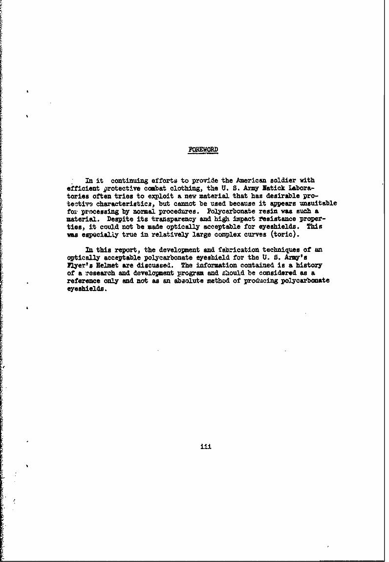
FOREWORD
In it continuing efforts to provide the American soldier withefficient protective combat clothing, the U. S. Army Natick Labora-tories often tries to exploit a new material that has desirable pro-teativ, characteristics, but cannot be used because it appears unsuitablefor prcessing by normal procedures. Polycarbonate resin was such amaterial. Despite its transparency and high impact resistance proper-ties, it could not be made optically acceptable for eyeshields. Thiswas especially true in relatively large complex curves (toric).
In this report, the develomwent and f brication techniques of anoptically acceptable polycarbonate eyeshield for the U. S. Ar'sFlyer's Helmet are discussed. The information contained is a historyof a rosearch and development program and sliould be considered as areference only and not as an abaolute method of producing polycarbonateeyeshields.
iii
-i

cOirTENTS
Page
List of Tables
List of Figures
Abstract
1. Ltroducion
2. Eyeshield Desia 2
3. Mold Design 3
4. Material Selection 7
5. Material Processing and Molding 12
6. ,alt.y Control 15
7. Discussion 16
8. Sumary 18
9. References 20
LIST OF TAB S
Flow Rates of Polycarbonate Resis as Determined by 8the Extz-xion Plastometer Melt Viscosity
I. Flow Rates of Polycarbonate Resins as Determined by 8Molding Eyeshields
II' Physical Properties of Polycarbon.te Resin 9
iV Ballistic Limit in Feet Per Sercond of Folycarbonate Resin 11
V Effect of Tinting on Clear Polycarbonate Resin to 11Eliminate Natural Coloring
Vi Molding Parameters 14
iv

LIST OF FItGLRESpoF
1 A. Acrylic Eyeshield Guide Cemented to EyeshieldB. Polycerbonate Eyeahield Guide Molded as an Integral
Component of the EyeshieldCross Section: Polycarbonate Eyeshield Guide and. AcrylicEyeshieid Guide Inserted into Lyeshield Track
Diagram of First Develolpenta! Mold to Produce OpticallyAcceptable Polycarbonate Visors
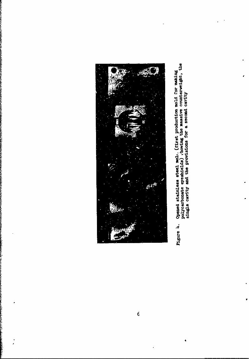
4 Opened Stainless Steel Mold (First Production Mold forMaking PolJycarbonate eashields) Showing the MassiveCounterweight, the Single Cavity and the Provisions fora Second Cavity
5 Typical Stress-Strain Curve for Molded PolycarbonatePlastic Using Low, Nedium o'c High Melt Viscosity Resin
6 Initial Inspection of' Eyeshield is Made by the MachineOperator at the 20-Ounce, 400-Ton Insection MoldingMachine
7 Three Basic Operations Required to Fabricate the Poly-carbonate eyeshield are shown in Stages:
a. Molding Operationb. Removal of Sprice by Mold Operatorc. Removal of Gate and Flash to Finish the Dyeshield.
V

The need to provide U. S. A-y aircrewmen with increased eye pro-tection saw a production technique developed to make optically acceptable,shatter- and impact-resistant eyeshields from polycarbonate resin. Itwas found that production quantities of optically transparent poly-carbonate lenses can be manufactured with a great deal of reliabilityby nujectionmolding processes. njection-molding of polycaronate
lenses employs standard equilpent and techniquea These, however, mustbe adjusted to account for the idiosyncrasies of the resin, e.g.,hygroscopic and flow characteristics.
In this fabrication project, the mold used was end-gated and highlypolished. Of three available grades of re3in, the material with thelowest molecular viscosity provided the best results. The develoImentmolds produced about 75,000 acceptable eyea:hields which were madeavailable to U. S. Arny and Air Force airmen for immediate tactical u3e.
The polycarbonate resin characteristics and molding techniquesthat influenced the design of the eyesbield, and the developient ofthe fabrication technique are discussed. Also discussed are factorsthat governod the selection of material type, mold design, and qualityassurance considerations,
vi
,a

Di-ELOP~~ PE ?AWXCATIOi OF A POI RBONE E ESHLD FORTHE U. S. AM & FIER' S HEMUT
1. Introduction
The U. S. Army is engaged in a continuous research and developmentprogram to provide maximum head protection to the aircrewmen against allhazardous and climatic environments. Each new technological developm~entis scrutinized to determine if it may, in any form, satisfy or up-grade
Lprotective requirements for the combat soldier. It was in this contextLthat polycarbonate resin was investigated for possible use in protecting
the eyes from impinging fragments. Besides resisting shattering andpenetration by fraengts, the eyeshield used by aircrewmen should notspall when impacted and, in addition, must provide protection againstsunglare and flash fires. Many transparent plastics were previouslyevaluated against these requirements; each was rejected because ofdeficient physical properties, unsatisfactory optics, or productiondifficulties.
The standard eyeshield. used to protect the eyes against sunglare,windblast, an,' flash fires i3 made from acrylic resin. This material iseasily formed into many lens shapes which provide ercellent optics.A,rylics, however, *re relatively brittle and will shatter smewhat likeglass when they a& impacted. A requirement for protacting the eyesagainst impacts and ainging fragments could not be satisfied byacrylic resin in the tkdickness that is used for the eyeshield (about0.090-Inch). Yet medical statistics report that mony facial and eyeinjuries result from either primary or secondary fragmenjs or fromshards or spall generated from impacted acrylic shields.Ll]
Initial investigations of polycarbonate resin revealed that thisplastic would not shatter or spall when exposed to a ballistic-type,low-mass, high-velocity impact. Although the earliest polycarbonateresins evaluated exhibited poor color and could not be consideredsuitable for an optical device, industry was encouraged to improve theoptical characteristics of the resin because of its potential pro-tection capabilities.
The exploitation of polycarbonate resin resulted iu a reduction ofi' s amber color first to light yellow, and then to a tinge of strawcolor. Transparent polycarbonate resin, with good color, is readilyavailable in sheet form and is also available as molding pellets whichcan be molded into transparent shapes. Optically transparent oroptically acceptable lens of polycarbonate resin, however, were stilloutside the state-of-the-art,
Primary efforts for making polycarbonate lenses or eyeshields wereconcerned with a thermo-forming method which started with an extrudedsheet. These techniques did not yield successful xesults because thequality of optics obtained was limited to that of the extruded sheet.Because of the nature of tie manufacturing process, these sheets con-tained variations in thickness, striae, and other inherent flaws andstresses which introduced optical aberrations in a lens.
Casting operations were considered necessary to eliminate inherentfaults and make a polycarbonate eyeshield with desired optical charac-teristics. Since custing of polycarbonate resin was outside the presentstate-of-the-art, "casting" had to be interpreted in the broadest sense.Liquid polycarbonate could be poured between parallel surfaces underhigh heat and pressure. This suggested injection-molding. Optics ofan injection-molded lens would then depend on parallelism of the mold,physical characteristics of the mold's surfaces and controlled shrinkagein the mold.
In conjunction with the Mine Safety Appliances Company*, the U. S.Any Natick Laboratories developed an injection mold and the processingtechnique to make a polycarbonate eyeshield for the U. S. Army Aircrew-man' s Helmet.
2. fyeshield Design
The configuration and critical dimensions of the standard large.size acrylic eyeshield were retained. The same shape eyeshield is alsoused by the U. S. Air Force in its large-sJze HGU-2A/P Flight helmet.Except for the lower edge, the contours of the eyeshield are similar tothose used with the Navyts large APH-6A flight helmet.
The standard eyeshield is made from metbylmethacrylic resin and
requires five operations to fabricate:
a. Casting optical grade sheets
b. Thermo-formiizg or blow-molding the lens
c. Trimming and finishing the lens
d. Molding eyeshield guides
e. Adhering guides to the eyeshield
* Contrac MD9-l29-AW332 2
I2
By injection-molding a polycarbonate resin eyeshield with integratedguides, the number of fabricating operations was reduced to two: molding,i then trivming and finish~mg.
~To make the eyeshield with integral guides, a redesign of the guides
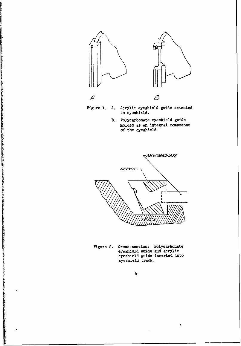
lwas necessary to obtain a molding without undue internal stresses. Acontinuous guide similar to that. in the standard acrylic eyeshield wouldhave presented difficulties in filling the mold and would present apotential shrinkage problem. To overcme these difficulties, the guideswere split into two bearing surfaces, one on each end of the eyeshieldedges (Figure 1). The split guides were groc.ved along their length toreduce their bulk, thereby reducing the probability of distortion dueto differential shrinkage of heavier sections. The critical dimensionsand bearing surfaces of the split guides were not cbanged from those ofthe older nontinuous guides (Figure 2).
3. MoldDesig
A single-cavity injection mold was designed with fan-gating on oneend and a conical runner (ligure 3). The mold was made to produce oneeyeshield with the intention of adding a second cavity and force duringthe development program (location of gate precluded a balanced set-upof the mold), thus requiring a counterweight which was built as partof the mold (Figure 4). The size of the mold base dictated the size ofthe machine to be used. The only machine available with the requiredplaten size was a 20-ounce, 450-ton injection molder. it was ultimatelydetermined that a single-cavity mold could be made smaller and lighter,but not in the current design. The current mold design, even with asingle cavity, would require it to be counterbalanced in the machine.
Two molds were made. The first was designed and used successfullyuntil it broke under pressures of production, Benefiting from thisexperience, a second mold with a single cavity was made.
The first set of mold Inserts (cavity and core) were made from420 cast stainless steel hardened to 40-50 Rockwell "C". Although asubstantial number (about 25,000) of eyeshields were produced and themold was subjected to a total of about 60,000 shots, it did exhibit anumber of shortcomings. The cast mold surfc wv-ld not take a suitablepolish for polycarbonate optical moldings. L2J The ability to retain apolish is an important characteristic for mold steels, especially sofor polycarbonate resin because it will faithfully transfer the moldsurface to the lens. The mold surface also stained or somehow reactedwith a residue from the polycarbonate resin. Periodic polishings wererequired to remove the stains and to maintain a clean, smooth surface.This resulted in excessive down time that would be considered pro-hibitive during production.
3
I
Figure 1. A. Acrylic eyeshield guide cementedto eyeshield.
B. Poycarbonate eyeshield guidemolded as an integral compoenntof the eyeshield.
,XVI YrAA8---r
Figure 2. Cross-section: Polycarbonateeyeshield guide and acrylic
eyeshield guide inserted into6yeshield track.

A~W I-CVTY-TW
COA'tZTME /1/ / P A
Fiue3SiOrMo is evlpetlmodt rdc~ opicaly ccepabl poycaronae vsrL
CAW
43 w
H
43 43
pe

The multiple polis.img of the mold emphasized the importance of thesurface finish aId the relative degree of moothness required. With eachsuccessive polishing, the optical dstortion exhibited by the eyeshieldwas reduced, thereby confirming that distortion, the only apparent opticaldeficiency encountered, was due to surface optics and could be corrected.
To increase prcuctivity by reducing the nsed for frequent polishings,the cast stainless steel mold surfaces were chrcie-.plated. This finishpermitted cleaning of surfaces while the mold w-s in the machine After9bout 60,000 shots =~d abowut 25,030 an.. epts-!e eye-hields, the stainlesssteel mold developed hairline cracks whi.S could not be polished out.
A second mold was made. This mold. was desired to overcme short-comings of the cast stairless-steel mold. It wa6 a corventional moldbase and inserts were made from forged H13 steel, a deep air-hardeuingsteel which will harden throiAout a rather large cross-sectiono L3JThe insert surfaces were plated with a niokel alloy to protect the moldsurfaces from corrosive residual products and to permit easy cleaning.
Ejection of the eyeahield frcm this mold was accomplished with onlythree straight knockout pins, one on the sprue which formed the apexof a triangle and the other two forming the base on the fan gate at itsJunction with the eyeshieldo
Polycarbonate resin has the quality of faithfully duplicating themold surface. It is, therefore, mandatory to attain a surface (polishedas perfectly as possible) to reduce the degree of optical aberrationscaused by surface imperfection. No surface finish standard has beenestablished; inadequate polishing would result in deficiencies thatwould probably manifest themselves as distortions which could, however,be uinimized as the surface finish is impr..ed. Plaeti.g the surface,whether it is done with chrome or nickel, will not necessarily improvethe finish. Plating will only make the mold surface durable, and mayserve to magnify inherent surface defectso
Both halves of the mold are channeled so that the mold tempera-tur e may be maintained by circulating water. The mold is end-gated witha fan gate. This is the recaended ronventic&al t. of gate designedto mold thin-walled, long-edged items like the eyesbield. A typicalmold design used to make the eyeshield is shown in Figure 3o
4. Material Selection
At the time of this develomant, there were only two major producersof polycarbonate resin in the United States. Each manufacturer producedthree grades of resin. These resins may be classified as having high,
7
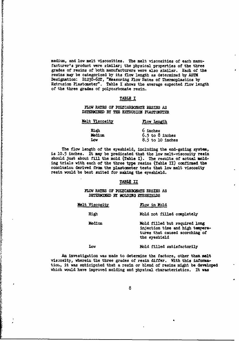
medium, and low melt viscosities. The melt viscosities of each manu-facturer's product were similar; the physical properties of the threegrades of resins of both manufacturers were also similar. Each of theresins may be categorized by its flow length as determined by ASTMDesignation; D1238-62, "Measuring Flow Rates of Thermoplastics byExtrusion Plastometer". Table I shows the average expected flow lengthof the three grades of polycarbonate resin.
TABLE I
FLOW RATES OF POLCARBONATE RESINS ASDETERMIED BY THE EMUSION PIASTC0TER
Melt Viscosity Flow Length
High 6 inchesMedium 6.5 to 8 inchesLow 8.5 to 10 inches
The flow length of the eyeshield, including the end-gating systa,is 10.5 inches. It may be predicated that the low melt-viscosity resinshould just about fill the mold (Table I). The results of actual mold-ing trials with each of the three type resins (Table II) confirmed theconclusion derived from the plastometer tests that low melt viscosityresin would be best suited for making the eyeshield.
TABLE II
FLOW RATES OF POLYCARBONATE RESINS ASDETERMIED BY MOLDING ErESHIELDS
Halt Viscosity Flow in Mold
High Mold not filled completely
Medium Mold filled but required longinjection time and high tempera-tures that caused scorching ofthe eyeshield
Low Mold filled satisfactorily
An investigation was made to determine the factors, other than meltvis.osity, wherein the three grades of resin differ. With this informa-tiob, it was anticipated that a resin or blend of resins might be developedwhich would have improved molding and physical characteristics. It was
8
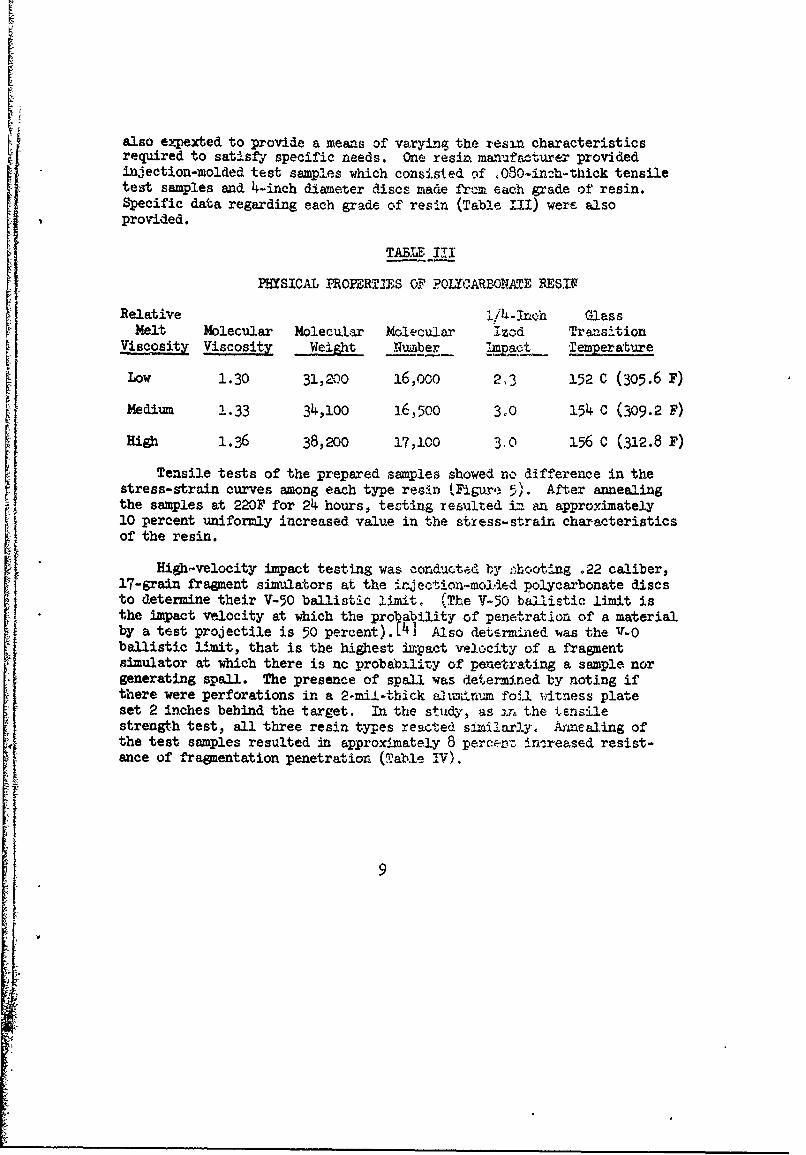
also expexted to provide a means of varying the res:n characteristicsrequired to satisfy specific needs. One resin manufacturer providedinjection-molded test samples which consisted of 080-in:h-thick tensiletest samples and 4-inch diameter discs made from each grade of resin.Specific data regarding each grade of resin (Table III) were alsoprovided.
TABUE III
PHYSICAL PROPERT/ES OF ?OYCARBONATE RESIN
Relative 1! h-/4 n" GlassMelt Molecular Molecular Molecular izod Transition
Viscosity Viscosity Wight Numiber !.L2np Teper ature
Low 1.30 31,200 16,000 2,3 152 C (305.6 F)
Medium 1.33 34,1oo 16,5oo 3.0 154 C (309.2 F)High 1.36 38,200 17,100 30 156 C (312.8 F)
Tensile tests of the prepared samples showed no difference in thestress-strain curves among each type resin (Figure 5). After annealing
the samples at 220F for 24 hours, testing resulted in an approximately10 percent uniformly increased value in the stxess-strain characteristicsof the resin.
High-velocity impact testing was conducted by ,hooting .22 caliber,17-grain fragment simulators at the injectio'n-molded polycarbonate discsto determine their V-50 ballistic l.mit, (The V-S0 ballistic limit is
the impact velocity at which the pro ability of penetration of a materialby a test projectile is 50 percent).[4 Also determined was the V-0ballistic limit, that is the highest impact velocity of a fragmentsimulator at which there is nc probabilit.y of penetrating a sample norgenerating spall. The presence of spall was determined by noting ifthere were perforations in a 2-mil-thick alriunm foil witness plateset 2 inches behind the target. In. the study, as DxT the tensilestrength test, all three resin tyles reacted similarly. Anmealing ofthe test samples resulted in approximately 8 perc:rc. in.reased resist-ance of fraguentation penetration (Table IV).
9

600-
500
400
Mz 300:D0CL
200
100
0- r
10 20 30 40 50
PERCENT ELONGATION
Figure 5. Typical etress-strain curve for molded polycarbonateplastic using low, medium or high zelt viscosity resin
10t 4
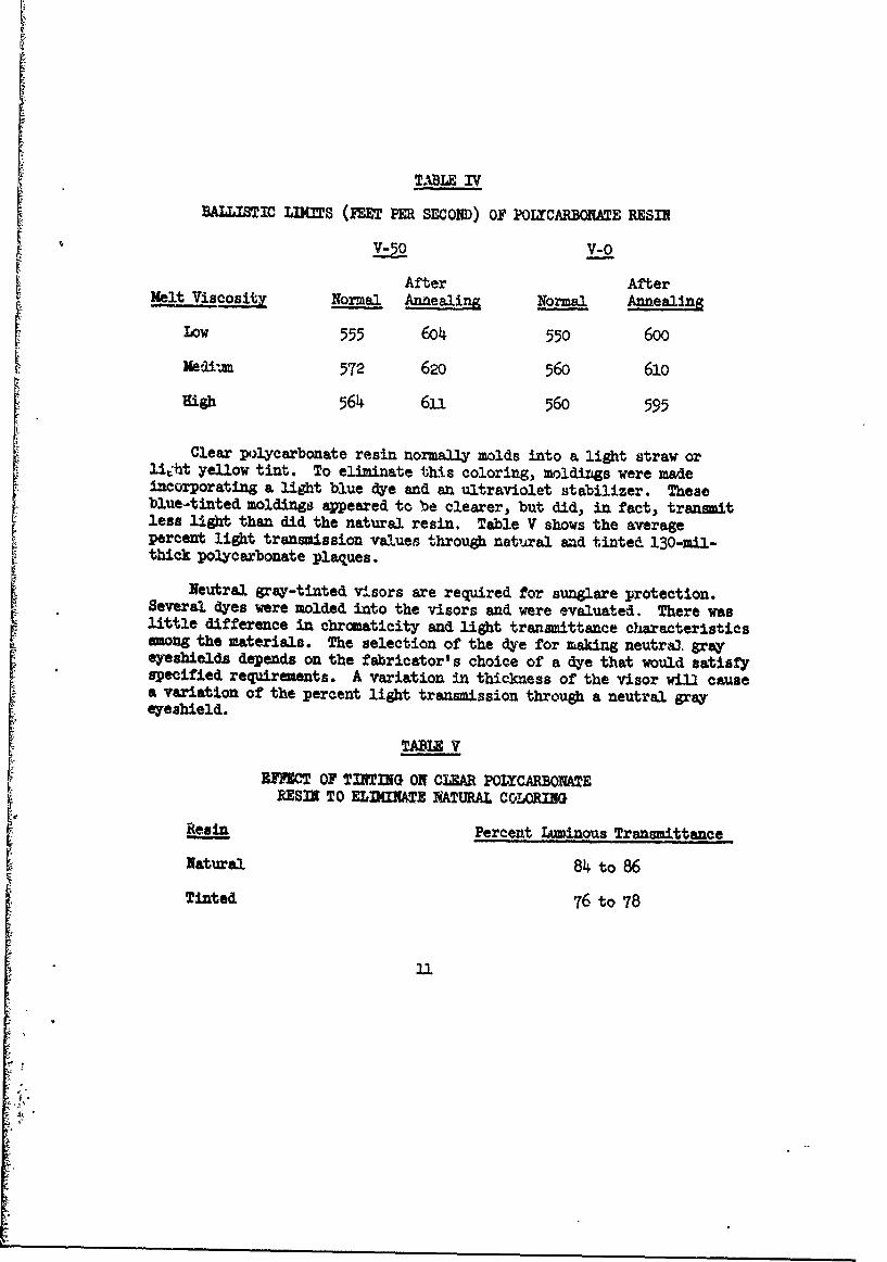
TABLE IV
BALLISTIC LIKrS (FET PER SECOND) OF POLYCARBONATWE RESIN
L_ LO V-0
After Aftermelt Viscosity Normal Anaealing Normal Annealing
Low 555 604 550 600
Kedl=im 572 620 560 610
High 564 6U 560 595
Clear polycarbonate resin normally molds into a light straw orli.ht yellow tint. To eliminate this coloring, moldings were madeincorporating a light blue dye and an ultraviolet stabilizer. Theseblue-tinted moldings appeared to be clearer, but did, in fact, transmitless light than did the natural resin. Table V shows the averagepercent light transmission values through natural and tinted 130-mil-thick polycarbonate plaques.
Neutral gray-tinted visors are required for sunglare protection.Several dyes were molded into the visors and were evaluated. There waslittle difference in chromaticity and light tranamittance characteristicsamong the materials. The selection of the dye for making neutraj. grayeyeshields depends on the fabricator's choice of a dye that would satisfyspecified requirements. A variation in thickness of the visor wi3l causea variation of the percent light transmission through a neutral grayeyeshield.
TABLE V
[ IF=I OF TINTIG ON CLEAR P0ICARBOXATERESIN TO ELINMTE NATUrAL COLORING
Resin Percent Luminous Transmittance
Natural 84 to 86
Tinted 76 to 78
11
5. Material Processing and Molding
Polycarbonate resin absorbs relatively small quantities of moistureunder normal service conditions (less than .05 percent water is absorbedas a result of immersion). To obtain satisfactory molded parts, however,it is essential to use d resin. Prior to molding the eyethield, thepolycarbonate resin pellets were stored in a drying oven at 2.500F for sixhours. They were then loaded into the injection-molding machine's dry-ing hopper which was maintained at a temperature of 200-2500F. Greatcare was taken to assure that the resin was not contaminated. If theresin should be inadequately dried, the resulting moldings might containstreaks or bubbles or appear misty. Moisture in the resin ight alsocause embrittlement of the molding or significantly reduce its impactstrength.
Conventional equipment and techniques are used in the injection-molding of polycarbonate eyeshields, Molders using standard injection-molding machines and processes should not encounter serious problems.They must, however, treat pclycarbonate resin as an entity, adjust tothe material's idiosyncrasies, and try not to identify it with otherresins. Injection-molding ofpolycarbonate resins requires highortemperatures, higher pressures, and shorter injection times than isgenerally associated with other resins.
Because of the size of the mold used for this develoment, a 20-ounce, 450-ton injection-molding machine was used (Figure 6). With aproperly designed, single-cavity mold, it is thought possible, however,to use a 5-ounce, 200-ton molding machine. Molding parameters used forthis development are shown in Table VI.
In the discussion of materials, it was shown that the maximn flowlength that could be expected from the low melt-viscosity resin is 10inches (Table I). The length of the eyeshield mold approaches themaximum expected flow length. This mold includes the eyeshield, gateand runner. Because the mold must be filled over a critical length,the injection operation is sensitive. The polycarbonate melt mustbe kept in a fluid state at the highest possible temperature withoutburning or scorching.
The temperatur e ost melt is controlled by heating chambertemperatures, screw speed, and length of time in the heating chamber.It appears that the most critical of these three variables is thelength of time (residence time) in the heating chamber.
12
* '

0
410
.44

Residence time is determined by the nunber of shots in the chember.Only a 2-1/2 ounce shot is required to fill the eyeshield mold while theheating chamber of the 20-ounce machine used for this development stored15 ounces of resin. Each shot had, therefore, been in the heatingchamber for six heats. The length of this residence time and the varia-tions due to press "open time" make temperatures difficult to control.Urless these variables are adequately controlled, molding will reretin short shots and burned shots.
Because of the long residence time, cycle time also becones acritical consideration. The size of the mold precluded the use of asmaller injection-molding machine, thereby reducing the residence time.Nevertheless, with an understanding of the process and careful controlof the variables, satisfactory eyeshields were manufactured.
The finishing operation starts at the injectiou-moling machine.The operator, after removing the visor And making an Initial inspectionfor obvious deficiencies (Figure 6), removes the sprue, the gate andflash (Figure 7). The visor then moves to another station where thesharp edges are broken. This operation was troublesome and was notbrought to production efficiency at the conpletion of the developeenteffort. All visor edges were either scraped, filed or honed.Mechanized attempts to break the edge of the visor seemed to push orflow the resin thereby creating an undesirable burr.
TABLE VI
MOLDIN PARAUTZR
Cylinder Temperatures
1A Adapter 670-700 F,Front 65o-68o F,Center 650-680 F.Rear 500-580 F.
Full Injection 4-9 ,econdsInjection Hold 7-14 secondsClamp 20-h0 secoadsMold T!mperature* 140-180 F,Injection Speed 2-4 seconds(one shot)Screw Return Time 4-8 secondsScrew Speed 20-50 rpmFeed (travel of ram) 1-1/8 to 1-1/2 inchesInjection PressureHigh 20,000 psiLOW 14,000-17,000 psi
*Outlet water temperature
144

6. Stgity Control
With each start-up and with each new batch of resin, molding conditionsmust be checked and, when needed, proper adjustments made to produce satis-factory eyeshields. From that time until the next start-up or new batch ofresin, the resulting eyeshields should hee a minimal change in theirproperties. Most defects in the eyeshields caused by deficient moldingtechniques were readily apparent to visual inspection. These defects areprimarily:
a. Discoloration or buring
b. Short shots
c. Contamination
Th defects can readily be detected with the unaided eye by lockingthrough the eyeshield, from a distance of about 12 inches, toward asuch as pits, bubbles, scratches, lint and other foreign particles not
readily detgetale by visuaL inspection can be detected by specificationtests. L5) ) 7
If the defects are present and are not readily detectable by thespecified tests, then it may be assumed that they will not affect theserviceability of the eyeshields.
Contamination can be reduced by good housekeeping and scrupulouscare in handling of the resin from the time of its manufacture, receiptat the plant, to the final molding operation. Further reduction of con-tamination may be accomplished by proper purging of the injection-moldingsystem and cleaning of the mold. Purging may not always be feasible;the machine should then continue operating until the contamination runsitself out.
Burning and short shots usually are the results of an inadvertentchange in molding conditions or fabrication procedures. Visual inspec-tion of each eyeshield removed from the mold would permit timely adjust-ment of the production operation to reduce the incidence of burning orshort shots.
Brittleness of the eyeshield may also be an indication of domolding conditions. The brittleness test used for safety glassesiloat
in to drop a 1.5-inch-diameter steel ball 50 inches onto the lens. The
15

1c'ycarbonate eyeshield did not fracture, crack, or craze as a result ofthis impact test even at temperatures ranging fcom 1850F to -40oF. Theeyeshield was al.o impacted with an 8pound ball dropped .48 inches anddid not fail. Brittleness or potential brittleness of a polycarbonateeyeshield can be detected, howev4r, by means of a high rate of loadingimpact, such as a ballistic impact.
The specification for the eyeshie..,d requires that it withstand three550 feet per second impacts, one in the center and one in each criticalvision area, without cracking, penetration o. spall. Th se impacts aremade with a .22 caliber, 17-grain fragment simulator. 1J Cracking,spall, or punch-out at velocities of 550 feet per second or below couldbe an indication of a defective molding operation. This deficiencyprobably is caused by either an unevenly heated mold or a mold that isnot hot enough to :,sclude undue stresses. By adjusting mold tempera-ture and cylce, these stresses could be minimized, thereby reducing theincidence of brittleness failvre.
All other defects are generally optical deficiencies. As previouslystated, once operations are adjusted to produce satisfactory eyeshields,properties sbould not vary bignificantly until the machine is shut down,or possibly a new batch of resin is introduced. Any change in opticalproperties would indicate process or ,wold deficiencies.
7. Discussion
As a result of producing an excess of 40,000 eyeshields with thetwo developmental molds and testing optical properties, the factorsthat would influence optical characteristics were determined.
Lminous transmittance, or total light transmission, is the ratioof visible light (electromagnetic energy wavelengths between 430 and 730millimicrons) passing through the eyeshield to the total incident light.Light transmission can be affected first by the batch of polycarbonateresin being used, and then by the processing technique. Burning ordiscoloration of the eyeshield will significantly rednce the eyesield'sluminous transmittances. This characteristic was measured tdth a record-ing spectrc-photometer. A chi square test was run on the date for "good-ness of fit"; the data approximate a normal distribution adequate topermit the use of normal statistical techniques. The process capabilityof the polycarbonate resin for this phase of the developmient permittedan average light trausmission of 38 percent with six standard deviations(S.D.), ranging from 32 to 94 percent. This range encompasses 99.86percent of the specified production of eyeshiel-s; 95.90 percent of theeyeshields exhibited 84 to 92 percent luminous transmittance.
16
• i

Diffuse Tranamittances, or haze measurements, were made by means ofa recording spectrohotmeter. A chi square test of the haze test dataindicated that the data approximate a normal distribution, Tho eyeshieldsexhibited an average of transaittance of diffused light of 0.78 percentwith a standard elevation of 0.45 percent. Thus, 99.86 percent (six S.D.)of the visors will exhibit haze readings between 0.0 and 2.13 percent.The primary cause of haze is the insufficient drying of the resin. Hazemay alao be caused by an inadequately polished mold surface.
Ultraviolet Transmittance is the total light transmitted through theeyeshield in the erythermal band of 250 to 320 millirdcrons. Essentially,no ultraviolet light was shown to be transmitted within the capabilitiesof the spectrophotmeter used for these measurements. This characteristicappearm to be a function of the polycarbonate materiel. The moldingprocess should in no way affect the ultraviolet transmittance. Testingfor this characteristic may, with cnnfidence, be conducted on a batchbasis only.
Other characteristics affecting optics may be caused by pbysical
defects in the eyeshield as opposed to the "optical" properties discussed.These deficiencies are concerned with the bending of light passing throughthe eyeshield. Three deficiencies may be collectively categorized as
prismatic deviation:
a. Vertical prismatic deviation
b. Horizontal prismatic deviation
c. Spherical and cylindrical power
Defects in these characteristics are virtually always a functionof the mold. Distortion and haze may also be controlled by the mold,but to a much lesser degree.
Horizontal Prismatic Deviation is a shift in direction of theviewerls line of sight. This deviation may be present because of unevenformning or congealing of the resin. Nonparallel surfaces or variationsthickness will also cause deviation of line of sight. This defect maybe controlled by a well-designed mold with smooth parallel surfaces,uniform heating and/or cooling capabilities, and sufficient clempingpressure and suitable locks to keep the mold from separating or movingunder high pressures.
Vertical Prismatic Deviatiou is a shift in position of the vi ,wer'sline of sight. This defect is also a function of material thickness.It is, in fact, the same as horizontal prismatic deviation, except for
17

the direction in which transmitted light is shifted. Vertical prismaticdeviation is caused by the same factors that influence horizontal pris-matic deviation and will undoubtedly be overcome with the same correctiveactions.
Spherical and Cylindrical Power defines the curvatures of the eye-shield. This is solely controlled by the configuration of the mold.This is measured by determining the magnification present in eachcritical visua3 area of the eyeshield.
Distortion may be a function of the molding process; it may also becaused by a defective mold. Uneven heating and/or cooling causing striaeor internal stress will cause cistortion. The deficiency will also mani-fest itself if the eyeshield varies substantially in thickness over smallareas. Polycarbonate resin's characteristics of duplicating the mold
surface will cause distortion if the mold surface is less than "perfect".
A test for distortion will also reveal imperfections not visibleto the unaided eye nor revealed by other tests. These imperfectionsinclude surface scratches, pits and entrapped foreign bodies.
8. ~sWm
Production quantities of optically transparent polycarbonate lensescan be manufactured with a great deal of reliability by injection-moldingprocesses. The eyeshield for the U. S. Army Flyer's helmet is producedin this wanner.
The mold used was end-gated and was highly polished. Of threeavailable grades of resin, the material with the lowest molecularviscosity provided the best results.
Injection-molding of polycarbonate lenses employs standard equip-ment and techniques. These, however, must be adjusted to account forthe idiosyncrasies of the resin, e.g., hygroscopic and flow charac-teristics.
The developnent molds produced about 75,000 acceprable eyeshieldswhich were made available to U. S. Army and Air Force airmen for imediatetactical use.
18

Figure 7.Three basic operations required to fabricate thepolycarbonate eyeahield are shown in stages:
a. Mol~ding Operationb. Removal of sprue by mold operatorc.* Removal of gate and flash to finish
the eyeshield
19

9. References
1. Coates, S. B., Jr., and J. D. Beyer, Wound Ballistics, Office
of The Surgeon General, Department of the Army, 1962
2. Balint, R. D., Mold Finishing, SPE Journal, March, 1966
3. Schettig, J. R., How to Select Mold Steels, Plastic TechnogyO
4. Military Standard, mIL-STD-662A, 15 June 1964, BallisticAcceptance Test Method for Personal Armor Material
5. Military Specification, MIL-V-22272B(WP), 28 January 1965,Visors, Protective Helmet
6. Military Specification, MIL-Z-38169 (USAF), 26 March 1963,General Specification for Lenses, Goggle and Visor, Helmet,Optical Characteristics
7. Military Specification, MIL-V-43511(GL), 30 June 1967 andAmendment-2, 13 May 1968, Visors, Flying Helmet, Polycarbonate
8. United States of America Standard Institute, Standard Z2.1-1959Head, Eye, and Respiratory Protection
20

UNCLASSIFIEDSecurity Classification
DOCUMENT CONTROL DATA. R & D(Security clasulfication of title, body of abstract and indexing annotation must be entered when the overall report I. Claeeified)
I. ORIGINATING ACTIVITY (Corporate author) 1ah REPORT SECURITY CLASSIPICATION
U.S. Army Natick Laboratories UNCLASSIFIEDNatick, Massachusetts 017602 GROUP
S. REPORT TITLE
DEVEHER AD FABRICATII OF A POLYCA ZE EYE HIELD FOR THE U. S. APF'LYER ' S HELMET
4. DESCRIPTIVE NOT9S (Type of report and inclusive dale&)
5. AUTHOR(S) (FirSt name, middle initial, iast name)
Abraham L. LastnikBruce T. GleavlyJohn B. Brown
9. REPORT DATE 7a. TOTAL NO. OF PAGES 7b. NO. OF REFS
June 1970 20 8CONTRACT OR GRANT NO. 9a. ORIGINATOR'S REPORY NUI'RDRIS)
DM9-329-AiM-332-,. PROJECT NO. 71-3-CE (C&PLSEL-76)
l.664713D547C. 9b. OTHER REPORT NO(S) (Any other numbers t hmay be a oigod
this report)
d.
10. DISTRIOUTION STATEMENT
This docment has been approved for public release and sale; its distribution
is unlimited.
II. SUPPLEMENTARY NOTES 12. SPONSORING MILITARY ACTIVITY
U. S. Army Natick LaboratoriesNatick, Massachusetts 01760
IS. ASTSRACT
- -The need to provide U.S. Arvy aircremen with increased eye protection saw aproduction technique developed to make optically acceptable, shatter- and impact-resistant eyeshields from polycarbnate resin. It was found that productionquantities of optically transparent polycarbonate lenses can be manufactured witha great deal of reliability by injection-molding processes. Injection-molding ofpolycarbonate lenses employs standard equipment and techniques. These, however,must be adjusted to account for the idiosyncrasies of the resin, e.g., hygroscopicand flow characteristics.
In this fabrication project, the mold used was end-gated and highly polished.
Of three available grades of resin, the material with the lowest molecular viscosity
provided the best results. The development molds produced about 75,000 acceptableeyeshields which were made available to U.S. Army and Air Force airmen for imediate
tactical use.
The polycarbonate resin characteristics and molding techniques that influnced
the design of the eyeshield, and the develolmt of the fabrication techniq:;e are
discussed. Also discussed are factors that governed the selection of material
type, mold design, and quality assurance considerations.
DD ~ ~ ~ Z ID.17 ::rnF hbPU14711. JAN 04. WHICM 4DDP F.*,M,1,.73 e, [11 Il
UWL AS SIFED
UICLASSIFIEDSecurity Ciesslicatlon
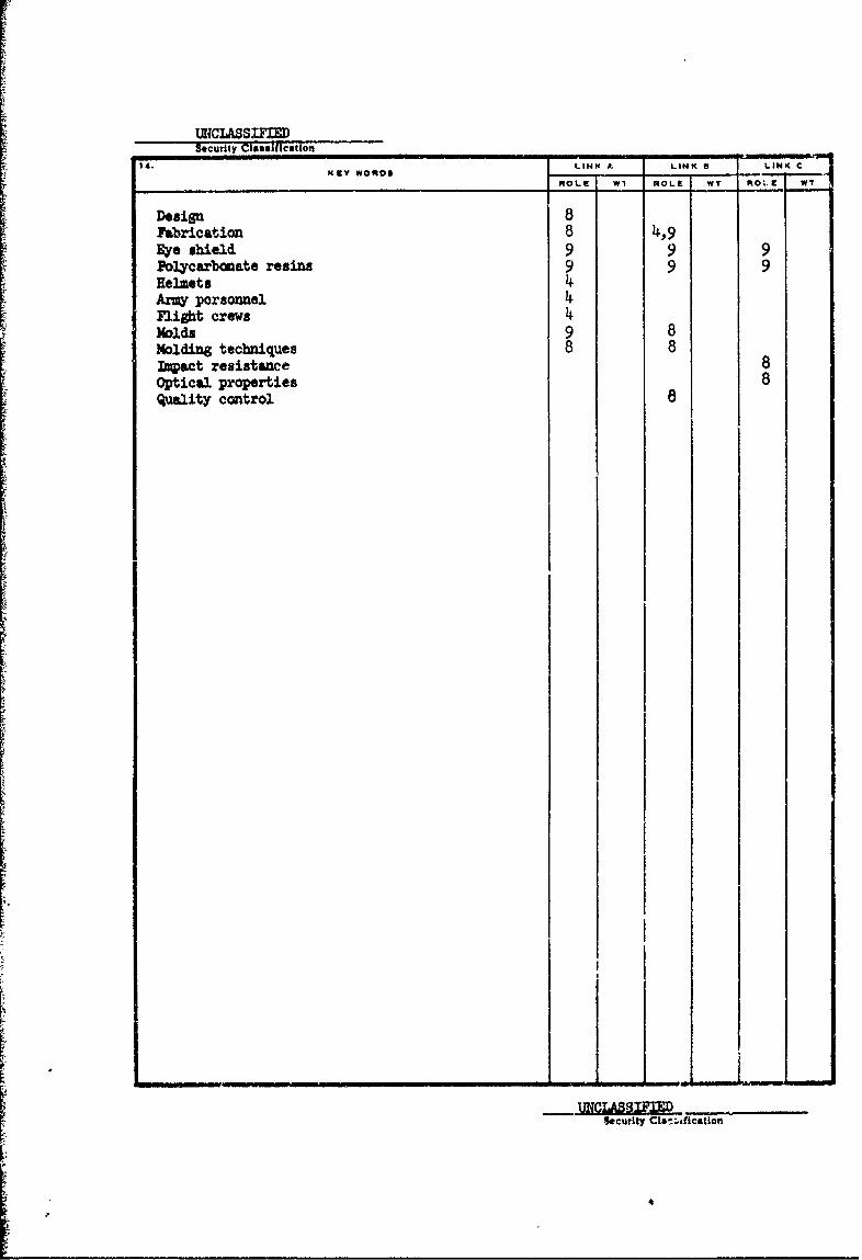
14. WORDS LINK A LINK S LINK C
RPIOLE W1 ROLE WT MOl.EWT
Design 8Fabrication 8 4,9Rye shield 9 9 9Polycarbonate resins 9 9 9Eelmets 4ArmW porsonnel 4Flight crews 4Molds 9 8Molding techniques 8 8Impact resistance 8Optical properties 8Qality control e
I I- ~ J ~Li ____