development and implementation of a biaxial contact ... · computer program called opensees. this...
TRANSCRIPT

PROJECTE O TESINA D’ESPECIALITAT
Títol
Development and implementation of a biaxial contact
element to analyze pounding in highway bridges with
deck rotation under bidirectional seismic excitation
Autor/a
Vicente A. García Marín
Tutor/a
Alex H. Barbat
Departament
Departamento de Resistencia de Materiales y Estructuras en Ingeniería
Intensificació
Ingeniería Estructural
Data
8 de febrero de 2015

i
Development and implementation of a biaxial
contact element to analyze pounding in highway
bridges with deck rotation under bidirectional
seismic excitation
Vicente A. García Marín
M. Eng. Thesis
Department of Civil and Environmental Engineering
Tokyo Institute of Technology
Tokyo, Japan
Dipartimento di Ingegneria Strutturale
Politecnico di Milano
Milan, Italy
Escola Tècnica Superior d’Enginyers de Camins, Canals i Ports
Universitat Politècnica de Catalunya (UPC)
Barcelona, Spain
March, 2015

ii
Abstract
During the last strong earthquakes, the impact between closely adjacent structures was reported as
one of the major causes of collapse in buildings and bridges. This impact is also called seismic pounding
and is due to the different dynamic characteristics of those neighboring structures that make them to
vibrate out of phase and become them in potentially dangerous. In the case of bridges, seismic pounding
is the impact produced between deck-deck and deck-abutment. In the common engineering practice,
bridges are designed with expansion joints or gaps to allow the expansion of the deck because of
temperature, shrinkage or creep of concrete. Since this gap cannot be removed generally, it is a vulnerable
part of the bridge when earthquake occurs. In addition, seismic pounding produces severe damage in
bridges and even collapse.
In this study, a detailed overview of the last strongest earthquakes since San Francisco earthquake in
1906 until Tohoku earthquake in 2011 is presented focusing on different types of damages produced in
bridges. Within all these different ways of failure and unlike other types of damages, seismic pounding
has been less studied although it was demonstrated to be one of the main causes of damages in bridges
during the last great earthquakes. Unidirectional and bidirectional seismic pounding are distinguished and
a deep review in the literature is provided to know what has been done so far in the field of seismic
pounding simulation in bridges. After that, a brief introduction of physical nature of impact as well as the
main existing impact force models divided into linear and non-linear are presented. Then, a proposed
impact force model based on a modified Kelvin-Voigt model where frictional forces are involved is
developed. This proposed contact element is implemented as a biaxial contact element in an open-source
computer program called OpenSees. This computer program was developed at University of Berkeley
(California) and is based on the Finite Element Method. It is widely used in earthquake research because
of is a powerful tool to deal with dynamic problems where non-linearity’s are involved. Moreover, the
new contact element was validated for unidirectional directional using an experiment carried out at
Harbin Institute of Technology (China) with encouraging results.
Finally, three real and different bridges located in California are taken as seed bridges to study
seismic pounding in bridges. Furthermore Kobe, Loma Prieta, Chi-Chi and Landers earthquake are
chosen as input ground motions in order to have two pulse-like (Kobe and Loma Prieta) and two far-field
(Chi-Chi and Landers) earthquakes. The isolated bridges are modeled in OpenSees and subjected to 2,688
non-linear time history analysis simulations where the gap and the skew angle of decks are the parameters
used to study the seismic bridge response. The results show how important the skew angle is and its
influence in the performance of the bridge being 45º the worse scenario when pounding occurs.

iii
Acknowledgements
I would like to express my sincere gratitude to my three thesis supervisors, Associate Professor Anil
C. Wijeyewickrema (Tokyo Institute of Technology, Japan), Assistant Professor Luca Martinelli
(Politecnico di Milano, Italy) and Professor Alex Barbat (Universitat Politècnica de Catalunya, Spain) for
their continuous support and guidance during this thesis work. Their moral and expert advice has played a
key role in the successful completion of this work. I am also grateful for the critical insights they put into
my work.
I am also grateful to Ms. Yumiko Hori (International Student Exchange Division of Tokyo Institute
of Technology), the secretaries of Anil Lab Ms. Emiko Serino and Ms. Toshiko Kabashima for the help
before, during and after my internship in Tokyo. I would like to express my sincere thanks to my lab-
mates in Japan for their friendship and help, Ms. Porjan Tuttipongsawat, Mr. Makoto Kimura, Mr. Itaru
Takahashi, Mr. Yuma Asai, Mr. Chou Soklin, Mr. Rohit Kumar, Ms. Anuja Shrestha and Ms. Monika
Maharjan. In addition, I would like to thank especially my lab-mates Mr. Samith Buddika, Mr. Satish
Bhagat and Mr. Deepak Pant for their technical and moral support and for showing me the knowledge
knows no boundaries.
I am also indebted to Jaume Cirera, Elisa Romero and Nina Dechkova for all the years we spent in
Barcelona together and where without their moral support and friendship I would not be able to finish my
studies successfully. Moreover, I would like also to express my gratitude to Eduard Barguès for making
my life easier, his support and kindness in Milan.
Last but not least, my deepest gratitude to my whole family for being always available when I
needed it. Especially, I would like to thank my mother Amparo Marín and my grandmother Carmina Díaz
for teaching me how to face the troubles and what is even more important: how to overcome them.
Thanks to them, a normal child who lived in a modest neighborhood in Alicante was able to grow up and
fulfill the dream of living in the downtown of the biggest city in the world.

iv
Table of Contents
Abstract ii
Acknowledgements iii
Table of Contents iv
List of Figures vi
List of Tables xi
List of Symbols xii
1. Introduction
1.1. Damage to bridges in the past earthquakes 5
1.2. Seismic pounding in bridges 10
1.3. Review of Previous studies 13
1.3.1. Unidirectional pounding 15
1.3.2. Bidirectional pounding 16
1.4. Objectives and scope 17
1.5. Outline of thesis 18
2. Impact Force Models
2.1. Physical nature of impact 19
2.2. Numerical simulation of impact 21
2.3. Existing Impact Force Models 23
2.3.1. Linear models 23
2.3.2. Non-linear models 27
2.4. Proposed Impact Force Model 31
2.4.1. Mathematical formulation 33
2.4.2. Numerical implementation in OpenSees 44
2.4.3. Experimental validation 51
2.4.3.1. Unidirectional validation 51
2.4.3.2. Bidirectional validation 62
2.5. Conclusions 66
3. Bridge Description and Design
3.1. Bridges selection and locations 67
3.2. Ground motion selection and scaling 70
3.3. Seismic Isolators Design 76
3.3.1 Lead Rubber Bearings Design 79
3.4. Design of Bridge A 82
v
3.5. Design of Bridge B 86
3.6 Design of Bridge C 88
3.7. Conclusions 90
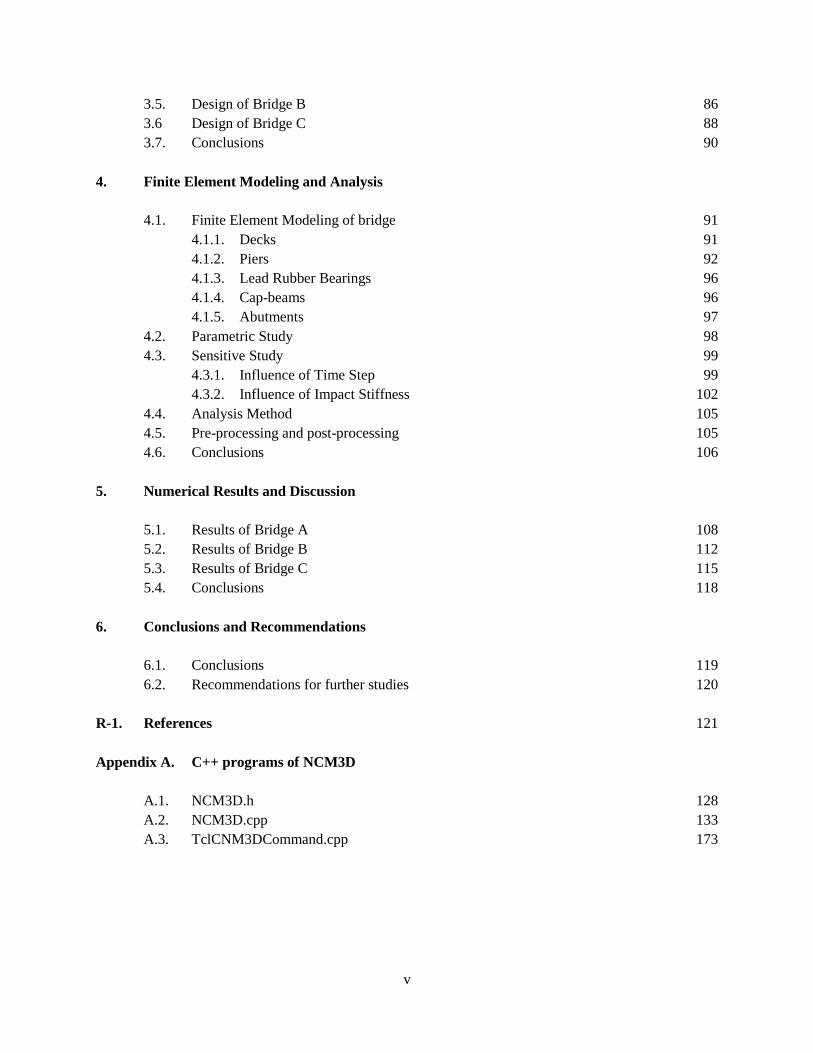
4. Finite Element Modeling and Analysis
4.1. Finite Element Modeling of bridge 91
4.1.1. Decks 91
4.1.2. Piers 92
4.1.3. Lead Rubber Bearings 96
4.1.4. Cap-beams 96
4.1.5. Abutments 97
4.2. Parametric Study 98
4.3. Sensitive Study 99
4.3.1. Influence of Time Step 99
4.3.2. Influence of Impact Stiffness 102
4.4. Analysis Method 105
4.5. Pre-processing and post-processing 105
4.6. Conclusions 106
5. Numerical Results and Discussion
5.1. Results of Bridge A 108
5.2. Results of Bridge B 112
5.3. Results of Bridge C 115
5.4. Conclusions 118
6. Conclusions and Recommendations
6.1. Conclusions 119
6.2. Recommendations for further studies 120
R-1. References 121
Appendix A. C++ programs of NCM3D
A.1. NCM3D.h 128
A.2. NCM3D.cpp 133
A.3. TclCNM3DCommand.cpp 173

vi
List of Figures
Fig. 1.1. Damage produced by Great Kanto earthquake in (a) Tokyo and (b)
Yokohama in 1923.
Fig. 1.2. Scheme of the Ring of Fire.
Fig. 1.3. Collapse of (a) I-5 at Gavin Canyon (Los Angeles county) and (b) a highway
bridge in Granada Hills (California) produced by Northridge earthquake.
Fig. 1.4. Collapse of (a) approach span of Nishinomiya-ko bridge and (b) Hanshin
Expressway toppled to the north (from Kawashima) produced by Kobe
earthquake.
Fig. 1.5. Collapse of (a) the Shih-Wui bridge and (b) the Wu-His bridge in highway
Tai-3 produced by Chi-Chi earthquake.
Fig. 1.6. List of the strongest earthquakes year by year since 2000.
Fig. 1.7. (a) Abutment slid towards river showing the movement of the Rio Viscaya
bridge footings and piles during the Costa Rica earthquake and (b) the
relative rotation between abutment and deck of the same bridge.
Fig. 1.8. (a) Heavy flexural cracking on south face of pier #38 and (b) failed splices
and layered longitudinal steel of southeast corner of pier #45 (Hanshin
expressway), (c) plastic hinge developed at about one third above the
ground level (Niigata earthquake, 2004) and (d) failure of the column
(Hanshin expressway, Kobe earthquake 1995).
Fig. 1.9. Close-up view of shear failure of (a) highway pier in Granada Hills
(California) and (b) La Cienaga - Venice highway bridge pier showing
cracked and spalled concrete cover produced by Northridge earthquake
(1994).
Fig. 1.10. (a) Damage to cap beam of supporting east span of cable-stayed bridge (Chi-
Chi, Taiwan 1999), (b) knee joint failure of Cypress Street Viaduct
(California 1989), (c) reinforced concrete abutment footings of Rio Cuba
highway bridge badly cracked (Costa Rica, 1991) and (d) northeast corner of
steel pier #55 (Hanshin expressway, 1995).
Fig. 1.11. (a) Unseating between deck supported on bearing and abutment (Chi-Chi,
Taiwan 1999) and (b) piers and abutment moved and collapsed into the river
because of pier footings suffered liquefaction (Costa Rica, 1991).
Fig. 1.12. Sketch of two-span highway bridge supported on bearings at middle pier and
abutments without pounding.
Fig. 1.13. (a) Impact between decks and abutments when decks move outwards and (b)
impact between decks when decks move inwards.
Fig.1.14. Pounding between (a) deck-abutment, (b) deck-deck and (c) rotation between
two bents during Northridge earthquake. Pounding between (d) deck-
abutment, (e) rotation deck-abutment and (f) relative displacement between
decks in Nishinomiya-ko bridge during Kobe earthquake.
Fig. 1.15. Relative displacements between decks during (a) Northridge earthquake and
(b) Kobe earthquake.
1
2
3
3
4
5
8
8
9
9
10
10
11
12
13

vii
Fig. 1.16. Top view of (a) unidirectional pounding and (b) bidirectional pounding of
base-isolated bridge.
Fig. 2.1. Force-deformation relationship for an instance of impact (a) according to
compression and restitution phases and (b) according to different stages.
Fig. 2.2. (a) Simulation of impact as overlap-material and (b) contact element between
impacting bodies.
Fig. 2.3. Comparison between damping ratios for linear models developed by
different researchers.
Fig. 2.4. Typical force-indentation relationship of (a) linear spring model, (b) Kelvin-
Voigt model, modification of Kelvin-Voigt model by (c) Komodromos et al.
(2007) and (d) Pant and Wijeyewickrema (2010).
Fig. 2.5. Comparison between damping ratios for non-linear models developed by
different researchers assuming equal to one.
Fig. 2.6. Typical force-indentation relationship of (a) Hertz model and (b) Hertz
damping model.
Fig. 2.7. Model for decks.
Fig. 2.8. Sketch of the proposed contact element with linear springs and non-linear
dashpots in both directions and friction in tangential direction.
Fig. 2.9. Relative displacements along local normal ( ) and local tangential ( )
direction when (a) deck 1 is target deck and deck 2 is attack deck and when
(b) deck 2 is target deck and deck 1 is attack deck.
Fig. 2.10. (a) Representation of pounding when L2 is the attack node and deck 2 is the
target deck showing (b) the normal ( ) and tangential ( ) forces involved
during the impact.
Fig. 2.11. Contact between (a) and deck 2, (b) and deck 1, (c) and deck 2 and
(d) and deck 1.
Fig. 2.12. Detail of a typical contact between node and deck 2.
Fig. 2.13. Example of pounding when attack node is and deck 2 is the target deck
showing the equations of the straight lines that define both decks.
Fig. 2.14. Illustration of linear interpolation for deck 1 (target deck) when is attack
node where (a) it represents all components of displacements, (b) x
components and (c) y components of displacements.
Fig. 2.15. Representation of a typical impact between deck 1 (attack deck) and deck 2
(target deck) at different time steps.
Fig. 2.16. Illustration of relative displacement when deck 2 is attack deck and deck 1 is
target deck at time .
Fig. 2.17. (a) Compression and (b) restitution phase when attack deck is deck 1 and 2
respectively. (c) Restitution and (d) compression phase when attack deck is
deck 1 and 2 respectively.
Fig. 2.18. Sign convention when (a) deck 1 is attack deck and (b) when deck 2 is attack
deck.
14
20
23
26
27
30
30
31
32
34
35
35
36
37
38
38
39
40
41

viii
Fig. 2.19. Relocation of pounding forces when the attack node is (a) node , (b) node
, (c) node and (d) node .
Fig. 2.20. Definition and location of the local axis x and y for (a) contact element 1, (b)
contact element 2, (c) contact element 3 and (d) contact element 4 indicating
the attack node with a red rectangle.
Fig. 2.21. Console of OpenSees
Fig. 2.22. Overlapping area between (a) and as well as (b) between and .
Fig. 2.23. Bridge model on the shaking table during the experiment at Harbin Institute
of Technology.
Fig. 2.24. Schematic diagram of the measurement and control system. Units in mm.
Fig. 2.25. Variation of modal damping ratio with natural frequency .
Fig. 2.26. Sketch of the numerical model for unidirectional pounding validation.
Fig. 2.27. Absolute acceleration of (a) deck 1 and (b) deck 2 under Taft earthquake
without pounding. Absolute acceleration of (c) deck 1 and (d) deck 2 under
Kobe earthquake without pounding.
Fig. 2.28. Absolute acceleration of (a) deck 1 and (b) deck 2 under Taft earthquake
using NCM3D. Absolute acceleration of (c) deck 1 and (d) deck 2 under Taft
earthquake using the contact element developed by Guo et al. (2009).
Fig. 2.29. Representation of typical unidirectional pounding.
Fig. 2.30. Error E of the peaks of acceleration in (a) deck 1 and (b) deck 2 under Taft
earthquake.
Fig. 2.31. (a) Pounding force and (b) displacements of deck 1 and deck 2 under Taft
earthquake.
Fig. 2.32. Absolute acceleration of (a) deck 1 and (b) deck 2 under Kobe earthquake
using NCM3D. Absolute acceleration of (c) deck 1 and (d) deck 2 under
Kobe earthquake using the contact element developed by Guo et al. (2009).
Fig. 2.33. Error E of the peaks of acceleration in (a) deck 1 and (b) deck 2 under Kobe
earthquake.
Fig. 2.34. (a) Pounding force and (b) displacement of deck 1 and 2 under Kobe
earthquake.
Fig. 2.35. Displacements of the deck 1 and deck 2 along (a) X-axis and (b) Y-axis using
NCM3D under Taft earthquake.
Fig. 2.36. Displacement of the corner nodes , , and under Taft earthquake.
Fig. 2.37. Rotation of deck 1 and deck 2 under Taft earthquake.
Fig. 2.38. Absolute acceleration in X direction of (a) deck 1 and (b) deck 2. Absolute
acceleration in Y direction of (c) deck 1 and (d) deck 2. NCM3D is used.
Fig. 2.39. Normal pounding force and (b) tangential pounding force using NCM3D
under Taft earthquake.
Fig. 2.40. Comparison between absolute acceleration response with and without
pounding of (a) deck 1 and (b) deck 2 along X-axis and (c) deck 1 and (d)
deck 2 along Y-axis under Taft earthquake.
Fig. 3.1. Bridge A located in city of Ripon in California with coordinates 37° 45' 12"
N, 121° 08' 30" W.
42
43
44
50
52
53
54
55
56
57
58
59
59
60
61
61
62
63
63
64
65
66
67

ix
Fig. 3.2. Single pier of the Bridge A.
Fig. 3.3. (a) General view, (b) piers and (c) abutment of Bridge B located in city of
Tustin in California with coordinates 33° 46' 51.08'' N, 117° 49' 51.43'' W.
Fig. 3.4. Bridge C located in city of Ripon in California with coordinates 37° 45' 12"
N, 121° 08' 30" W.
Fig. 3.5. Generic design response spectrum.
Fig. 3.6. Design response spectrum along FN and FP of (a) location I and (b) location
II.
Fig. 3.7. Comparison between 5 % damped elastic pseudo acceleration response
spectra of the original ground motions and the design response spectrum
(DE) of both locations for (a) Fault Normal (FN) and (b) Fault Parallel (FP)
directions.
Fig. 3.8. Acceleration time histories of original ground motions: (a) Kobe (FN), (b)
Kobe (FP), (c) Loma Prieta (FN), (d) Loma Prieta (FP), (e) Chi-Chi (FN), (f)
Chi-Chi (FP), (g) Lardens (FN) and (h) Lardens (FP).
Fig. 3.9. Comparison between 5 % damped elastic pseudo acceleration response
spectra of matched ground motions and the design response spectrum for (a)
location I and FN, (b) location I and FP, (c) location II and FN, (d) location
II and FP.
Fig. 3.10. (a) Reduction of spectra accelerations by period increase and (b) increment
of the displacement demand by period increase.
Fig. 3.11. (a) Natural Rubber Bearing (NRB), (b) Lead Rubber Bearing (LRB) and (c)
Friction Pendulum System (FPS).
Fig. 3.12. Typical bilinear force-displacement relationship for Lead Rubber Bearing
(LRB).
Fig. 3.13. Comparison between lower and upper bound values for LRB in
unidirectional motion.
Fig. 3.14. Comparison of force-displacement relationship of LRB with UB values
between (a) unidirectional and (b) bidirectional motions.
Fig. 3.15. Typical circular Lead Rubber Bearing (LRB) with its main geometric
parameters.
Fig. 3.16. Cross section of Bridge A. Units in meters.
Fig. 3.17. Cross-section of the pier of Bridge A with the 60 reinforcing bars. Units in
meters.
Fig. 3.18. Force-displacement relationship of passive pressure force in abutments.
Fig. 3.19. Cross-section of Bridge B. Units in meters.
Fig. 3.20. Cross-section of Bridge C. Units in meters.
Fig. 3.21. Cross-section of a pier of Bridge C with the 60 reinforcing bars. Units in
meters.
Fig. 4.1. Sketch of deck model using elastic beam column elements in OpenSees.
Fig. 4.2. Sketch of fiber beam column element with some integration points.
Fig. 4.3. Different uniaxial materials of the RC section of a pier.
Fig. 4.4. Stress-strain relationship of the concrete02 model available in OpenSees.
Fig. 4.5. Stress-strain relationship of the steel02 model available in OpenSees.
68
68
69
71
72
73
74
75
77
78
79
80
80
82
83
84
85
87
89
90
92
93
93
94
95

x
Fig. 4.6. Schematic representation of the bearings of Bridge A, B and C.
Fig. 4.7. Schematic representation of abutments.
Fig. 4.8. Skewness.
Fig. 4.9. Displacements of deck 1 along (a) X direction and (b) Y direction using
NCM3D under Taft earthquake for different time steps.
Fig. 4.10. Accelerations of deck 1 along (a) normal and (b) tangential direction using
NCM3D under Taft earthquake for different time steps.
Fig. 4.11. Normal force of (a) the first impact and (b) a random impact. Tangential
force of (c) the first impact and (d) random impact for different time steps.
Fig. 4.12. Rotation of deck (a) 1 and (b) 2 direction using NCM3D under Taft
earthquake for different time steps.
Fig. 4.13. Displacement of deck 1 along (a) X and (b) Y direction using NCM3D under
Taft earthquake for different impact stiffness values.
Fig. 4.14. Acceleration of deck 1 along (a) normal and (b) tangential direction using
NCM3D under Taft earthquake for different impact stiffness values.
Fig. 4.15. Acceleration of deck 1 along normal direction using NCM3D under Taft
earthquake for different impact stiffness values.
Fig. 4.16. Rotation of deck (a) 1 and (b) 2 using NCM3D under Taft earthquake for
different impact stiffness values.
Fig. 5.1. Flowchart of all possible combinations used in the non-linear time history
simulations in OpenSees.
Fig. 5.2. Peak accelerations of deck 2 of Bridge A when (a) there is no pounding and
(b) pounding.
Fig. 5.3. Maximum displacements of deck 2 of bridge A for (a) DE and (b) MCE in
the case of LB.
Fig. 5.4. Maximum reaction force in the base of the pier of bridge A for (a) DE and
(b) MCE in the case of LB.
Fig. 5.5. Maximum displacements of deck 2 of bridge B for (a) DE and (b) MCE in
the case of LB.
Fig. 5.6. Maximum reaction force in the base of the pier of bridge B for (a) DE and
(b) MCE in the case of LB.
Fig. 5.7. Maximum displacements of deck 2 of bridge C for (a) DE and (b) MCE in
the case of LB.
Fig. 5.8. Maximum reaction force in the base of the pier of bridge C for (a) DE and
(b) MCE in the case of LB.
96
97
98
99
100
101
102
103
104
104
106
107
109
110
111
113
114
116
117

xi
List of Tables
Table 2.1. Representation of impact between two spherical bodies at various stages.
Table 2.2. Conditions for the identification of compression and restitution phases
depending on the attack deck.
Table 3.1. General properties of the seed bridges.
Table 3.2. Parameters of the design response spectrum (DE) for location I and II.
Table 3.3. Summary of the original ground motions.
Table 3.4. Comparison of PGA, PGV and PGD between original and matched ground
motions.
Table 3.5. Summary of the bounding properties of LRB for Bridge A, B and C.
Table 3.6. Summary of geometric properties of LRB.
Table 4.1. Summary of the input parameters used for concrete02 model in OpenSees.
Table 4.2. Summary of the impact stiffness for the abutments.
Table 4.3. Gaps (d) used for the simulations for each bridge.
20
40
70
72
73
76
81
82
95
97
98

xii
List of Symbols
Symbol Description
a Half-length of deck 1
ia Experimental peak of acceleration
ia Numerical peak of acceleration
A Total area of the cross-section of pier
sA Total area of reinforcement of pier
b Half-width of deck 1 and deck 2
c Half-length of deck 2
lc Damping coefficient of linear model
hc Damping coefficient of Hertz damping model
d Gap size
bd Lateral distance between reinforcing bars
BD Bonded diameter of lead rubber bearing
DD Displacement demand of elastomeric bearing
LD Lead diameter of lead rubber bearing
nE Normalized error of peak of acceleration
sE Modulus of elasticity of steel
tsE Slope of softening branch in tension for concrete
cf Concrete compressive strength
cuf Residual stress

xiii
tf Tensile strength of concrete
uf Crushing strength of concrete
NF Pounding force along normal direction
TF Pounding force along tangential direction
yF Yield strength of elastomeric bearing
g Gravity
h Height of cover plates of lead rubber bearing
abuth Height of abutment
BH Height of lead rubber bearing without cover plates
dk Post-elastic stiffness of elastomeric bearing
hk Impact stiffness of the Hertz model
lk Impact stiffness of the linear model
Nk Impact stiffness of the NCM3D in normal direction
Tk Impact stiffness of the NCM3D in tangential direction
Vk Vertical stiffness of elastomeric bearing
abutK Axial stiffness of the abutment
im Mass of body i
bwP Passive pressure force at abutment
r Coefficient of restitution
ct Thickness of cover plates of lead rubber bearing
st Thickness of steel shims of layers of lead rubber bearing
iu Displacement of deck i

xiv
iu Velocity of deck i
*
iv Velocity of node i after impact (stereomechanical approach)
w Width of cover plates of lead rubber bearing
abutw Projected width of the back wall of abutment
kx Global coordinate x of node k
Gy Deck centroid
ky Global coordinate y of node k
Angle between the normal vector of target deck and relative displacement of decks
Angle between the normal vector of target deck and relative velocity of decks
Ratio between post-elastic and elastic stiffness of lead rubber bearings
Indentation
Relative velocity of impact
0 Relative velocity just before the impact
0c Concrete strain at maximum stress
k Kinetic coefficient of friction
s Static coefficient of friction
Damping ratio
c Density of concrete
s Ratio of volume of hoop reinforcement (pier)

1
Fig. 1.1. Damage produced by Great Kanto earthquake in (a) Tokyo and (b) Yokohama in 1923.
(a) http://nisee.berkeley.edu/jpg/EERC_2002_0712/IMG0020.jpg, (b) http://nisee.berkeley.edu/jpg/EERC_2002_0712/IMG0015.jpg
Chapter 1
Introduction
Since long time ago, earthquakes have been one of the most unknown natural disasters for the human
beings due to the uncertainty of occurrence and high damage produced. In fact, the first seismic
excitations were studied by a Chinese philosopher called Chang Heng in 132 B.C inventing the earliest
known seismoscope (Dewey and Byerly 1969). This first seismoscope was intented to record both the
occurrence of earthquakes and the azimuths of their origins from the observer. During the following
centuries the seismic technology enhanced through the inventions such as the first seismoscope to record
the time of small earthquakes invented by Palmieri in the middle of nineteenth century and the first
seismograph of low intensity developed by Cecchi in 1875. Thanks to that, nowadays the newest
seismographs are equipped with electromagnetic sensors that can record the ground motions with high
accuracy and digitally. In addition, the launch of the first computers in the middle of twentieth century led
to suppose a significant stride for the earthquake research. Hence, the modern earthquake engineering was
born based on numerical methods and the high speed of processing supplied by the computers.
In the past, several strong earthquakes produced a relevant damage in buildings and civil structures.
The largest earthquake ever recorded was the Chile earthquake 9.5wM in 1960 with a material
damage estimated at 700 million dollars, many structures collapsed and however only dozens of people
died because of earthquake, surprisingly. This was essentially due to the warning given by small shock
that preceded the main earthquake by about 15 minutes (Rosenblueth 1960, 1961). Nevertheless, the
Great San Francisco earthquake 7.6wM in 1906 and the Great Kanto earthquake 8.3wM in 1923
can be considered the first strong ground motions well documented. In Japan, around 694,000 houses
were partially or completely collapsed (James 2011). The earthquake devastated Kanto region, specially
Tokyo and Yokohama city (Fig. 1.1(a), (b)) killing thousands of people.
(a) (b)

2
Since Great Kanto earthquake, there were several strong earthquakes in different points around the
word. However, All these points are mostly concentrated in a particular region called Circum-Pacific
Seismic Belt and widely known as Ring of Fire (Fig. 1.2). About 90 % of the world’s earthquakes and 81
% of the largest world’s earthquakes occur there (Kious and Tilling 2001). It has horseshoe shape and
belongs to the basin of Pacific Ocean.
Most of the last strongest earthquakes took place in this region. For instance, in 1989 Loma Prieta
earthquake 6.9wM provided some interesting insights into the effects of a great earthquake in an
urban setting (EERI 1989). Unlike other very damaging California earthquakes, such as San Fernando,
Coalinga or Whittier events (Priestly and Eeri 1988), Loma Prieta earthquake distributed damaged
throughout many counties. It was the largest earthquake occurred on the San Andreas Fault since the
Great San Francisco earthquake 7.9wM in 1906. Some years later, Northridge earthquake 6.7wM
damaged about 12,500 structures in 1994. Of 66,545 buildings inspected, 6 % were severely damaged and
17 % were moderate damaged (EQE 1994). Collapses and other severe damage forced closure of 11
major roads (Fig. 1.3(a), (b)) to downtown Los Angeles such as I-5, SR-14, I-10 and SR-118 (ITS 2002).
The next year, the Kobe earthquake 6.8wM shook the southern side of the main island of Honshu
(Japan) in 1995. After this earthquake 5,000 people were reported killed, more than 26,000 were injured
and over 300,000 were left homeless (Comartin et al. 1995). Kobe, Ashiya and Nishinomiya (Fig. 1.4(a))
areas were specially destroyed and therefore their transportation system. The Hanshin expressway (Fig.
1.4(b)) through the city was closed by transverse overturning and collapsed section of 18 spans (630 m of
total length) due to flexural and shear mode damage (Hashimoto et al. 2005). A number of major
expressways, rail lines and bridges, some of very modern design, were severely damaged. However, the
Akashi Kaikyo bridge, the longest suspension bridge in the world, was still under construction when
Kobe earthquake struck the city and the towers were moved by one meter increasing the main span from
1990 m to 1991 m and the change was easily accommodated in the slightly altered final design because of
only the towers were erected at the time. On the other hand, the Port of Kobe, much of which was new,
was also devastated by widespread and severely liquefaction and permanent ground deformations, which
destroyed more than 90 % of the port’s 187 berths and damaged or destroyed most large cranes (EQE
Fig. 1.2. Scheme of the Ring of Fire.
http://earthquake.usgs.gov/learn/glossary/images/ringoffire.gif

3
1995). Moreover, the damage to the capital stock, expressed at commercial exchange rates, was estimated
at US$114 billion, three times the recorded cost of any previous natural disaster in the history (Horwich
2000).
(a) (b)
(a) (b)
Taiwan is also a seismically zone located in the Ring of Fire and therefore not exempt to suffer
strong earthquakes frequently. Hence, in 1999 the Chi-Chi earthquake 7.7wM devastated Taiwan and
Taichung and Nantou counties specially. On one hand, over 2,400 lives were lost, more than 10,000
people were injured and left and estimated 100,000 people homeless. On the other hand, over 10,000
buildings collapsed and more than 7,000 suffered damage (Lee and Loh 2000). Moreover, highway
damage was widespread throughout Taichung and Nantou counties due to fault rupturing, collapsed or
crippled bridges, landslides, soil settlement and slope failures. Regarding traffic infrastructures, thirty of
590 inspected bridges on the island sustained damage. Of those, 5 bridges collapsed, 9 bridges required
major emergency repairs to sustain traffic and 16 bridges were damaged but rated safe (Dong et al. 2000).
Fig. 1.3. Collapse of (a) I-5 at Gavin Canyon (Los Angeles county) and (b) a highway bridge in Granada
Hills (California) produced by Northridge earthquake.
(a) http://nisee.berkeley.edu/jpg/5074_1631_0650/IMG0003.jpg, (b) http://nisee.berkeley.edu/jpg/5076_1631_2251/IMG0046.jpg
Fig. 1.4. Collapse of (a) approach span of Nishinomiya-ko bridge and (b) Hanshin Expressway toppled to
the north (from Kawashima) produced by Kobe earthquake.
(a) http://nisee.berkeley.edu/jpg/6324_3122_2969/IMG0054.jpg, (b) http://nisee.berkeley.edu/jpg/6317_3071_0981/IMG0026.jpg

4
In addition, those most seriously affected range from 3-span to 28-span. From the economic point of
view, the economic losses were around US$12 billion. Most of the collapsed bridges (Fig. 1.5(a), (b))
were located on the highway Tai-3 which runs north south through Taichung and Nantou counties and
coincides with the Chelungpu fault rupture.
There have been several strong ground motions around the world after Chi-Chi earthquake and every
year a strong earthquake occurs (Fig. 1.6). According to United States Geological Survey’s (USGS), the
largest earthquake since year 2000 was the west coast of northern Sumatra earthquake 9.1wM in
2004 when a big tsunami destroyed the coasts of Indonesia, Sri Lanka, Thailand and India. The last
significant seismic excitation due to nuclear troubles related to the earthquake was the Tohoku earthquake
9.0wM off the east coast of Japan in 2011.
The Tohoku earthquake is known as Great East Japan earthquake and triggered extremely destructive
tsunami waves that reached height over 39 m (Mimura 2011). The earthquake and tsunami destroyed an
important number of buildings and infrastructures in northeast Japan. The Japan National Police Agency
confirmed 15,550 deaths, 5,688 injuries and 5,344 people missing as well as 224,798 housing units
collapsed, 434,327 housing units partially damaged and 32,443 non-residential buildings damaged.
Moreover, infrastructure damage was also widespread with 3,546 areas along roads, 71 bridges and 26
parts of the railway system. The tsunami waves played a crucial role in the damage of the structures as
Fig. 1.5. Collapse of (a) the Shih-Wui bridge and (b) the Wu-His bridge in highway Tai-3 produced by
Chi-Chi earthquake.
(a) http://nisee.berkeley.edu/jpg/0021_3292_3456/IMG0032.jpg, (b) http://nisee.berkeley.edu/jpg/9187_3302_4395/IMG0068.jpg
Fig. 1.6. List of the strongest earthquakes year by year since 2000.
(b) (a)

5
Kosa (2012) concluded. The outflow of superstructures occurred to more than 300 bridges during the
Tohoku earthquake. Among those 300 bridges, 9 national way bridges, 14 prefectural road bridges and
101 railway bridges suffered losses. In addition, Bricker et al. (2012) carried out field surveys and
numerical modeling to show the influence of the deck inclination, flow speed and tsunami surge in the
deck failure. Curiously most of the bridges designed by post-1990 code were not damaged however in
some bridges designed by 1995 code rubber bearings and dampers were severely damaged (Takahashi
2012) contributing to the total damage of the bridge. The tsunami inundated area of 2400 km and the area
affected by the earthquake is still under reconstruction and the Japan Government estimates the final cost
between 16 and 25 trillion yen.
After doing a review of the largest earthquakes in the world in the last hundred years, it can be
noticed the importance of correct seismic design in the structures in order to avoid collapse and severely
damage produced by the ground motions. Conceptually, bridges are simpler structures rather than other
structures such as, for example, buildings, tunnels or dams. Nevertheless, because of this conceptual
simplicity and therefore its limited redundancy unlike buildings, bridges are more sensitive to be affected
by earthquakes. Therefore, a deep knowledge of the failures produced by strong earthquakes is needed in
order to avoid them in the future.
1.1 Damage to Bridges in the Past Earthquakes
Past earthquakes showed the limitations of the structural design of some bridges under strong ground
motions. These limitations cause different types of failure making evidence the weak points of the seismic
bridge design. According Priestley et al. (1996), three different structural deficiencies can be identified in
different forms causing the main failures in bridges and are direct consequence of the elastic design
philosophy. The first deficiency is seismic deflection based on the specified lateral force levels that are
seriously underestimated because of the elastic design. The second deficiency is based on the first one
since seismic force levels were artificially low, the ratio to gravity load to seismic force adopted for
design was incorrect. Finally, inelastic structural actions and associated concepts of ductility and capacity
design are crucial to the survival of inelastic systems under severe seismic response and were not
considered in the elastic design process.
Because of these three deficiencies in the seismic bridge design, Priestley et al. (1996) divide the
potential failures of bridges into seven categories depending on the affected structural component:
1. Abutment slumping: The earth pressures increase under longitudinal response due to the
acceleration of the ground. Moreover, if impact occurs between the deck and backfill
generates and the soil is not well compacted an increment of pressure in the low level
pushing inwards and rotating the abutment. Costa Rica earthquake (EQE 1991) showed
several examples of this type of failure (Fig. 1.7(a), (b)).

6
2. Column failures: the columns failures can be divided into two different groups, a) flexural
strength and ductility failures and b) column shear failures.
a) Flexural strength and ductility failures. Until the middle of twentieth century, bridge
designers were generally unaware about ductility capacity what caused some
troubles. The typical ductility failures are:
Inadequate flexural strength. The elastic design assumed a low seismic
lateral force (6 % of dead weight in California) what underestimated a lot
the real seismic forces. In fact, empirical elastic response exceeded 100 %
this value. However, despite this large discrepancy the real strength
difference was much less due to the nature of the conservative analysis
adopted (Fig. 1.8(a)).
Undependable column flexural strength. The insufficient splice length above
the foundation does not allow to develop the strength of the reinforcing bars
and make the joint column-foundation a weak point under strong ground
motions (Fig. 1.8(b)).
Inadequate flexural ductility. Ductility is the property of being able to
deform through several cycles of displacements much larger than the yield
displacement without significant strength degradation. Therefore, in order to
survive intense seismic attack, structures must possess ductility. The lack of
ductility in the bridges was observed in past earthquakes (Fig. 1.8(c)) and
caused severely damage.
Premature termination of column reinforcement. The lack of the length
enough for the reinforcing bars along the column may cause the failure of
the whole column at the point where the reinforcement is missing. Kobe
earthquake caused this drawback especially in 1995 (Fig. 1.8(d)).
b) Column shear failures. Shear failure is a brittle failure and involves rapid strength
degradation. Short columns are particularly susceptible to shear failure as
consequence of the high shear/moment ratio and conservatism in the flexural
strength design of older columns (Fig 1.9(a), (b)).
3. Cap beam failures: Last earthquakes as Loma Prieta earthquake (1989) and Kobe earthquake
(1995) made clear three relevant deficiencies regarding cap beams. (i) Shear capacity, (ii)
premature termination of cap beam negative moment reinforcement and (iii) insufficient
anchorage of cap beam reinforcement into the end regions. This failure produces flexural
and shear cracks that decrease the strength of the cap beam (Fig. 1.10(a)).

7
4. Joint failures: Inappropriate shear reinforcement in joints between cap beams and piers may
produce the shear failure. In the past, several bridge designers did not consider these shear
forces to design the knee joints what means unsuitable shear reinforcement in that area (Fig.
1.10(b)).
5. Footing failures: In spite of the difficult of checking footings after an earthquake, some
failures were reported in the last earthquakes such as San Fernando earthquake in 1971 (Fig.
1.10(c)). Basically, the main deficiencies of footings are: (i) footing flexural strength, (ii)
footing shear strength, (iii) joint shear strength in the region immediately below the column,
(iv) anchorage and development of column reinforcement and (v) inadequate connection
between tension piles and footings.
6. Failures of steel bridge components: Steel bridge components are also susceptible to damage
although are lighter than equivalent concrete component (by about 30 %). For instance,
Kobe earthquake showed many examples of buckling of steel I-beam girders as result of
inadequate bracing. In addition, steel piers were also damaged (Fig. 1.10(d)).
7. Seismic displacements: Last earthquakes provided an important list of damage due to
underestimated seismic displacements as consequence of the elastic theory used for the
bridge design. The main failures related to seismic displacements are as defined below.
a) Span failures due to unseating at movement joints. Strong ground motions may
produce large displacements of spans in the direction of the earthquake and therefore
to exceed the seating width in joints between either deck-deck or deck-abutment.
This failure was reported in the most of past earthquakes (Fig. 1.4(a), Fig. 1.5(a) and
Fig. 1.11(a)).
b) Amplification of displacements due to soils effects. Soil where the bridge is built has
a crucial role in the displacements of the spans. Soft soils will generally result in
amplification of structural vibration response increasing the probability of unseating.
Moreover, if soil is composed of saturated sandy silts or silty sands, liquefaction of
the ground may occur. Bridges with simple supported span are particularly
susceptible to span failure due to liquefaction (Fig. 1.11(b)).
c) Pounding of bridge structures. Pounding between adjacent structures may occur
when the distance in insufficient. These unpredictable impacts produce high
pounding forces that can affect the behavior of the bridge and increase the seismic
displacements. In addition, pounding can also increase the shear forces of the piers
as well as acceleration response of bents (Fig. 1.14(a-f)).

8
(a) (b)
Fig. 1.7. (a) Abutment slid towards river showing the movement of the Rio Viscaya bridge footings and
piles during the Costa Rica earthquake and (b) the relative rotation between abutment and deck
of the same bridge.
(a) http://nisee.berkeley.edu/jpg/1351_3163_3946/046.jpg, (b) http://nisee.berkeley.edu/jpg/1351_3163_3946/044.jpg
(a) (b)
(c) (d)
Fig. 1.8. (a) Heavy flexural cracking on south face of pier #38 and (b) failed splices and layered
longitudinal steel of southeast corner of pier #45 (Hanshin expressway), (c) plastic hinge
developed at about one third above the ground level (Niigata earthquake, 2004) and (d) failure of
the column (Hanshin expressway, Kobe earthquake 1995).
(a) http://nisee.berkeley.edu/jpg/6317_3071_0960/IMG0020.jpg, (b) http://nisee.berkeley.edu/jpg/6317_3071_0960/IMG0040.jpg,
(c) http://nisee.berkeley.edu/jpg/EERC_2004_1129/IMG0002.jpg, (d) http://nisee.berkeley.edu/jpg/6317_3071_0981/IMG0029.jpg

9
(a) (b)
Fig. 1.9. Close-up view of shear failure of (a) highway pier in Granada Hills (California) and (b) La
Cienaga - Venice highway bridge pier showing cracked and spalled concrete cover produced by
Northridge earthquake (1994).
(a) http://nisee.berkeley.edu/jpg/5076_1631_2251/IMG0036.jpg, (b) http://nisee.berkeley.edu/jpg/EERC_2010_1906/Caltrans-NR-La-
Cienaga4.jpg
(a) (b)
(c) (d)
Fig. 1.10. (a) Damage to cap beam of supporting east span of cable-stayed bridge (Chi-Chi, Taiwan
1999), (b) knee joint failure of Cypress Street Viaduct (California 1989), (c) reinforced
concrete abutment footings of Rio Cuba highway bridge badly cracked (Costa Rica, 1991) and
(d) northeast corner of steel pier #55 (Hanshin expressway, 1995).
(a) http://nisee.berkeley.edu/jpg/9189_3291_1733/IMG0083.jpg, (b) http://nisee.berkeley.edu/jpg/1351_3163_1044/073.jpg,
(c) http://nisee.berkeley.edu/jpg/1351_3163_3722/img-066.jpg, (d) http://nisee.berkeley.edu/jpg/6317_3071_0960/IMG0055.jpg

10
Among all these different types of failure, this study is focused on pounding in highway bridges due
to strong ground motions.
1.2 Seismic Pounding in Bridges
Pounding is a complex phenomenon that occurs when two structures impact to each other due to
insufficient separation under strong ground motion and has been identified as cause of damage and
collapse (Anagnostopoulos 1994). Due to function requirements, highway bridges are set up a distance to
allow the out-of-phase displacement as consequence of temperature effects, creep or shrinkage of
concrete. This distance is also known as either gap or expansion joint and is located between deck-deck
and deck-abutment. On one hand, the difference of dynamic characteristics of neighboring structures as
well as asynchronous seismic excitation due to the length of the bridge may induce pounding. Because of
forces induced by pounding bridges can be severely damaged or even collapse. Three different kind of
gaps that can be distinguished in a common isolated highway bridge and are (i) gap between left abutment
and deck, (ii) gap between decks and (iii) gap between deck and right abutment as shown Fig. 1.12.
(a) (b)
Fig. 1.11. (a) Unseating between deck supported on bearing and abutment (Chi-Chi, Taiwan 1999) and
(b) piers and abutment moved and collapsed into the river because of pier footings suffered
liquefaction (Costa Rica, 1991).
(a) http://nisee.berkeley.edu/jpg/0021_3292_3456/IMG0065.jpg, (b) http://nisee.berkeley.edu/jpg/1351_3163_3946/042.jpg
Fig. 1.12. Sketch of two-span highway bridge supported on bearings at middle pier and abutments without
pounding.
Gap Gap Gap

11
On the other hand, impact occurs when the distance of the joint expansion (gap) becomes zero as
consequence of relative displacement of the bodies involved. Assuming decks as rigid bodies, pounding
can occur in either (i) left abutment (Fig. 1.13(a)), (ii) middle expansion joint (Fig. 1.13(b)), (iii) right
abutment (Fig. 1.13(a)) or (iv) different places simultaneously depending on the dynamic characteristics
of bridge system (piers, bearings and decks) as well as gaps in each location (left abutment, expansion
joint and right abutment). These impacts may change the dynamic behavior of the whole bridge and cause
severely concentrated damage because of pounding produces high forces in a short period of time.
Moreover, bridges are large linear infrastructures with principal axes defined clearly along lanes.
Therefore, bridges are sensitive structures to the direction of the seismic excitation.
Pounding is a common phenomenon when bridges are shaken by strong earthquakes and have been
widely reported during the last earthquakes. According to the National Information Service for
Earthquake Engineering (NISEE) by the Civil and Environmental Engineering Department of the
University of California (Berkeley), several highway bridges suffered as deck-abutment pounding as
deck-deck pounding as well as deck displacement induced by pounding that caused unseating of some
bents during Northridge and Kobe earthquake. In the case of Northridge earthquake, the Interstate-5/Hwy
14 interchange (Los Angeles county) suffered severely damaged as consequence to pounding between
deck and abutment (Fig. 1.14(a)) what caused unseating and collapse of deck. On the other hand,
Interstate-5/210 interchange (abutment 9), showed vertical and horizontal offset and damage along the
expansion joint (Fig. 1.14(b)). Regarding seismic displacements, Interstate-10/Fairfax Ave.-Washington
Blvd rotated at hinge between bents 3 and 4 (Fig. 1.14(c)) and an expansion joint of the Interstate-10/14th
St. bridge opened by 19 mm and moved to the side by 13 mm (Fig. 1.15(a)). During Kobe earthquake,
several pounding cases were reported. For example, the impact between steel deck and RC abutment (Fig.
1.14(d)), the off-ramp movement at abutment near bent #80 (Fig. 1.14(e)), deck displacement in (Fig.
1.14(f)) and deck displacement at pier #30 (Hanshin expressway) as shown in Fig. 1.15(b).
Fig. 1.13. (a) Impact between decks and abutments when decks move outwards and (b) impact between
decks when decks move inwards.
(b)
Impact Impact
Gap
Impact
Gap Gap
(a)

12
(a) (b)
(c) (d)
(e) (f)
Fig. 1.14. Pounding between (a) deck-abutment, (b) deck-deck and (c) rotation between two bents during
Northridge earthquake. Pounding between (d) deck-abutment, (e) rotation deck-abutment and (f)
relative displacement between decks in Nishinomiya-ko bridge during Kobe earthquake.
(a) http://nisee.berkeley.edu/jpg/5074_1631_0651/IMG0019.jpg, (b) http://nisee.berkeley.edu/jpg/5074_1631_0651/IMG0080.jpg,
(c) http://nisee.berkeley.edu/jpg/5074_1631_0650/IMG0040.jpg, (d) http://nisee.berkeley.edu/jpg/6324_3122_2969/IMG0047.jpg,
(e) http://nisee.berkeley.edu/jpg/6317_3071_0960/IMG0114.jpg, (f) http://nisee.berkeley.edu/jpg/6324_3122_2969/IMG0051.jpg

13
As it has been shown in the previous section, failures as consequence of pounding are as common as
other failures in bridges and the damage produced by this phenomena cannot be neglected. Therefore, a
deep study is needed in order to assess the pounding forces and its influence in the total bridge behavior.
However, before going ahead it is mandatory to review the relevant previous studies to know what have
been done until now.
1.3 Review of Previous Studies
Relevant previous studies about pounding in bridges as well as buildings are basically classified in
two main groups depending on the type of contact. The first group is unidirectional pounding and is
defined by unidirectional ground motion where the contact points (plane of impact) are known before
contact (Fig. 1.16(a)). Generally, it is considered unidirectional pounding when the direction of
propagation of seismic wave coincides with the longitudinal axis of the bridge. The second group is
bidirectional pounding and unlike unidirectional pounding, the contact points are unknown before impact
due to the relative displacement between the contact bodies (Fig. 1.16(b)) and it is defined by
bidirectional ground motion. It is widely established the longitudinal and transverse axis of the bridge as
main axis to define the components of the input earthquake. While unidirectional pounding has been
(a) (b)
Fig. 1.15. Relative displacements between decks during (a) Northridge earthquake and (b) Kobe
earthquake.
(a) http://nisee.berkeley.edu/jpg/5074_1631_0652/IMG0094.jpg, (b) http://nisee.berkeley.edu/jpg/6317_3071_0960/IMG0004.jpg

14
widely studied by researchers due to its easy implementation in computer programs, bidirectional
pounding deals with the difficulty that the contact points are unknown a priori and deck rotation and
friction force are also involved. In addition, pounding in bridges has not been as studied as pounding in
buildings. Nevertheless, much of the strides achieved in the field of buildings (base-isolated and fixed-
base buildings) are also used in bridge pounding. Furthermore, unlike unidirectional pounding, the
potential contact area in bidirectional pounding is a point if there is deck rotation. This contact point is
unknown because depends on the relative displacements that depends on the input ground motions and
dynamic properties of the bridge. Fig. 16(a) shows a typical unidirectional pounding between two
adjacent decks of base-isolated bridge along the longitudinal axis of the bridge while Fig. 16(b) shows a
typical bidirectional pounding of the same bridge produced by bidirectional earthquake. Note the rotation
of bearings.
Plane of impact
Impact
Fig. 1.16. Top view of (a) unidirectional pounding and (b) bidirectional pounding of base-isolated
bridge.
(a)
(b)

15
1.3.1 Unidirectional Pounding
There are few studies about unidirectional pounding of bridges unlike unidirectional pounding of
buildings that is phenomena widely studied. However most of the studies related to buildings can be also
used for bridges. One of the earliest studies about pounding was conducted by Wolf and Shrikerud (1980)
modeling pounding using a non-linear 1-Degree Of Freedom (DOF) system and an impact spring-dashpot
mechanism. In addition, they also studied pounding of typical reactor building by adjacent auxiliary
building during an earthquake using 2-DOF as well as an aircraft impact. After that, Maison and Kasai
(1990) conducted the formulation and solution of multi DOF equations of motion for a type of structural
pounding through the analysis of 15-stores building. In 1992, Anagnostopoulos studied mutual pounding
effect between two adjacent buildings modeled as lump masses using MDOF and bilinear force-
deformation characteristics for the impact model.
Pounding in bridges gained attention in 90s by researchers and in 1998 Tanabe et al. were some of
the first researchers who found pounding as cause of collapse in bridges. At the end of this decade, the
first studies that tried to explain the pounding phenomena in bridges appeared. On one hand, Pantelides
and Ma. (1998) conducted a study about the interaction between decks taking account the gap and impact
parameters. Furthermore, Malhotra (1998) developed a collinear impact between concrete rods with the
same cross-section but different lengths in order to use these results to formulate a realistic model for
concrete bridges. This study concluded that (i) seismic pounding generally reduces the pier forces, (ii)
large impacts forces generated in the superstructure are not transmitted to the bridge columns and
foundations and (iii) pounding does not increase the longitudinal separation at the hinges. A more
accurate numerical experiment was carried out by Kim et al. (2000a) modeling 6-span bridge as 3-DOF
(translational motion of superstructure along the main bridge axis and translational and rotational motion
of foundations). Kim et al. found pounding to affect the global motion of the bridge and may increase or
decrease the relative motions between adjacent bents according to the given conditions. Since the
beginning of pounding studies in bridges, researchers tried to avoid the pounding effect using dissipating
devices. For example, Kim et al. (2000b), Won et al. (2008) and Abdel Raheem (2009) investigated the
efficacy of using energy dissipating restrainers at expansion joints for preventing collapse of highway
bridges. In addition, Jankowski et al. (2000) analyzed several methods of reduction of the negative effects
of collision induced by pounding. The results showed that the influence of pounding on structural
response was significant in the longitudinal direction and significally depended on the gap size between
decks. Further studies indicated that the bridge behavior could be effectively improved by placing hard
rubber bumpers between segments and by stiff linking those segments. DesRoches and Muthukumar
(2002) carried out a similar study to determine the effects of frame stiffness ratio, ground motions
characteristics, frame yielding and restrainers on the pounding response of bridge frames. In addition, a
semi-active control using dampers were implemented to mitigate the non-linear response of bridges under
pounding effect by Ruangrassamee and Kawashima (2003).
During the following years, researchers adopted more complex models in order to investigate the
unidirectional pounding effect. In 2005, Chouw and Hao studied the effect of spatial variations of ground
motions with different wave propagation apparent velocities in soft and medium soil as well as the
influence of the soil structure interaction (SSI) on pounding response of two adjacent bridge frames. A
response spectra approach was presented by Jankowski (2006) in order to investigate pounding showing
peaks of pounding forces as functions of the natural structural vibration periods. A more complex

16
approach using dimensional analysis was conducted by Dimitrakopoulos et al. (2009) in order to
determine the dynamic response of several pounding oscillators subjected to pulse-type excitations.
Hence, the study showed that pounding structures such as colliding buildings or interacting bridge
segments may be most vulnerable for excitations with frequencies very different from their natural
frequencies. Moreover, one of the few experimental and analytical studies about pounding in bridges was
carried out by Guo et al. (2009) to reduce the pounding effect using magnetorheological (MR) dampers.
Once pounding phenomenon was understood better, researchers started to carry out parametric studies in
order to determine the effect of those parameters in the bridge response. For example, Bi et al. (2010)
investigated the minimum total gap that modular expansion joint (MEJ) had have to avoid pounding at
abutments and between decks and Li et al. (2013) considered the effect of abutment motion on bridge
pounding response.
1.3.2 Bidirectional Pounding
Regarding bidirectional pounding, the number of published studies is much less than unidirectional
pounding due to the difficulty of modeling. On one hand, Jankowski et al. published one of the first
studies about bidirectional pounding in 1998. They presented an analysis of pounding between
superstructure segments of base isolated bridge induced by propagating seismic wave in both directions
(longitudinal and transverse direction) using high-damping rubber bearing (HDRB) as isolation device.
Although this study takes account frictional forces, does not consider rotation of decks.
On the other hand, the 3D friction-model developed by Zhu et al. (2002) can be considered the
biggest stride in the last ten years because of led the transition from simplified bidirectional models to
general 3D model that can handle with non-linear materials and geometries. This 3D model included
Mohr-Coulomb friction and allows overlapping material. In addition, it utilizes Lagrange multiplier
method to impose restrictions. Nevertheless, it is incapable of dealing with non-linear materials during
contacts. The authors implemented the model in Dynamic Analysis if Bridge Systems (DABS), computer
program developed by themselves. Two years later, the same authors (Zhu et al. 2004) utilized DABS in
order to evaluate the effectiveness of pounding countermeasures and the serviceability of elevated bridges
subjected to severe ground motions. The peak and residual magnitude of gaps between girders as well as
maximum shear deformations of bearings were used to determine the serviceability.
When bidirectional ground motion is considered and the mass center and shear center does not
coincide, the rotation of decks play a crucial role in the pounding response. In that sense, the work of
Watanabe and Kawashima (2004) clarify the mechanism of rotation of skewed bridges. Skewed bridges
show particular structural response as result of poundings of the decks to the substructures and the effect
of restrainers. As occurred in the case of unidirectional pounding, the influence of the abutment during
pounding was also studied for bidirectional pounding and therefore the abutment behavior was also
included in the simulations when the phenomenon. For example, Aviram et al. (2008) evaluated the
sensibility of bridge seismic response with respect to three different abutment modeling approaches. An
interesting study about seismic torsional pounding between an asymmetric single story tower and
neighboring barrier under harmonic ground excitation was carried out by Wei et al. (2009). The numerical
simulations revealed that torsional pounding tended to be much more complex and unpredictable than
unidirectional pounding. Unlike Wei et al. (2009) that induced rotational pounding through the offset

17
between mass center and shear center applying harmonic ground excitation along one direction
(perpendicular to the barrier used for the study), Pant and Wijeyewickrema (2013) proposed a new
approach to evaluate the pounding response between a building and retaining wall subjected to
bidirectional earthquake. Hence, Pant and Wijeyewickrema concluded that considering unidirectional
excitation instead of a bidirectional excitation under strong near-fault motions provides highly
unconservative estimates of superstructure in some instances.
As occurred in the unidirectional pounding, Guo et al. (2011) carried out one of the few experiments
taking account bidirectional pounding. They presented an analytical model and pounding experiment of
highway bridge, especially focused on the point-to-surface pounding of bridge decks due to torsional
rotation, when subjected to extreme bidirectional earthquake excitations. The results showed that highway
bridge was vulnerable to deck rotation and point-to-surface pounding should be considered in the
structural design to lighten the pounding damage of the highway bridge under strong ground motion
excitations.
1.4 Objectives and Scope
The main objective of this study is to develop and implement a new contact element in order to
overcome the limitations of the previous studies discussed previously and assess the bridge response
under strong ground motions when pounding is induced.
On one hand, a new impact force model is presented based on the latest impact models as well as its
implementation in the open source FE program called OpenSees. An empirical validation of the proposed
contact element is carried out using the experiment results provided by Guo et al. (2009). Then, three real
bridges located in two different locations in California have been designed and modeled in finite elements
(FE) according to AASHTO LRFD Bridge Design Specifications (2012) as well as Caltrans (2013) in
order to assess the effect of unidirectional pounding and bidirectional pounding. Moreover, a detailed
design of lead rubber bearings (LRB) for each bridge is also conducted.
On the other hand, three dimensional non-linear seismic pounding analysis of the three mentioned
bridges are performed. Gap size and skew angle of the bridge are used for the parametric study. Design
Earthquake (DE) and Maximum Considered Earthquake (MCE) are also utilized in the analysis as well as
the lower bound and upper bound properties of the lead rubber bearings. In total, 2,688 non-linear
analysis using FEM are performed.
Finally, the response of bridges with and without pounding as well as both directions is evaluated in
with the purpose of estimate the effect that pounding in (i) the relative acceleration of decks, (ii) relative
displacement of decks, (iii) drift of pier, (iv) reactions on the base of pier (shear forces and moments) and
(v) behavior of lead rubber bearings.

18
1.5 Outline of Thesis
Chapter 2: A brief introduction of physical nature of impact is given. Different impact models to
simulate pounding numerically are reviewed. A new biaxial contact element to take account the deck
rotation is proposed as well as its implementation in OpenSees. In addition, an experimental validation of
the proposed contact element is also conducted for unidirectional pounding.
Chapter 3: Three real bridges located in two different locations in California are designed according
the American and Californian code (AASHTO LRFD BDS and Caltrans). A detailed explanation about
the lead rubber bearings design is given. Moreover, the scaling of the four ground motions used as
earthquake input (Kobe, Loma Prieta, Chi-Chi and Landers) for the numerical simulations are also
presented.
Chapter 4: Detailed finite element modeling of each part of the bridge and non-linear analysis is
presented. In addition, a sensitive study is conducted to investigate the suitability of the parameters used
in the parametric study (gap and skewness).
Chapter 5: Numerical results of three bridges are presented in terms of effect of unidirectional and
bidirectional pounding when the gap size and skew angle change. The results are focused on the effect in
(i) the relative acceleration of decks, (ii) relative displacement of decks, (iii) drift of pier, (iv) reactions on
the base of pier (shear forces and moments) and (v) behavior of lead rubber bearings.
Chapter 6: Main conclusions of the present study are presented as well as several recommendations
for further studies. Moreover, limitations of the proposed contact element are also discussed.

19
Chapter 2
Impact Force Models
Since Heinrich Hertz presented his theory to the Berlin Physical Society in January 1881 and
published his classic paper On the contact of elastic bodies in 1882, the study of contact mechanics has
changed substantially (Johnson 1985). Apparently, impact between two colliding bodies is a simple
phenomenon that can be seen every day in many different ways such as, for instance, walking (every
single step is an impact between shoe and ground), playing tennis (between ball and racket), baseball
(between bat and ball) or football (between foot and ball). However, impact is a very complex
phenomenon that occurs in a very brief period of time and involves many different variables what make it
difficult to model mathematically. Therefore, there have been different theories along the years in order to
simplify the phenomenon and make it easy to handle and useful for engineering applications.
According to the classic manuals of impact mechanics (Stronge 2000 and Goldsmith 2001), there are
four different methods to classify collisions depending on the deformations developed during impact, the
distribution of these deformations in each of the colliding bodies and how these deformations affect the
period of contact. In general, these four types of analysis for low speed collisions are (i) particle impact,
(ii) rigid body impact, (iii) transverse impact on flexible bodies and (iv) axial impact on flexible bodies.
This study is focused on a particular approach of the rigid body impact theory in order to study pounding
in highway bridges. To do that, the case of direct central impact is used to explain the physical nature of
impact.
2.1 Physical Nature of Impact
The physical nature of impact can be easily explained using the impact between two spherical
bodies. Fig. 2.1(a, b). shows a typical impact force-local deformation relationship during a direct central
impact.
The different stages that can be recognized in Fig. 2.1 are detailed with several remarks in Table 2.1.
The bodies approaching towards each other with certain velocity (stage I) and come in contact (stage II)
with a relative velocity just before impact 0 00 red bluev v v . After this stage, if 0 0v (assuming
positive velocity along the direction of red body in stage I and negative otherwise) the contact induces an
impact force which starts at point A as shown in Fig. 2.1 and depends on the overlapping of bodies
(indentation) . This contact force is applied in both colliding bodies at the same time with the same
magnitude but opposite direction. In addition, the indentation 1 depending on time is increasing during
the stages II and IV, where it reaches the maximum value max and 0 0v (stage IV) marked by point B
in Fig. 2.1. From stage II to stage IV the indentation is increasing due to relative movement of bodies and
this phase is known as compression phase. After reaching the point B characterized by the maximum

20
indentation max and relative velocity equal to zero, the indentation 1 starts to decrease and bodies start
to separate each other due to relative velocity becomes negative (stage V). However, the path to go from
stage V to stage VI in Fig. 2.1 is not the same to go from stage II to stage IV due to energy dissipation.
The phase characterized by stages V and VI where colliding bodies move in opposite directions (from
point B to point A) is known as restitution phase. The relative velocity at stage VI, just after the impact,
generally it is not the same than stage II what indicates that some amount of energy is lost during the
impact. The energy dissipation can be in two principal forms, one is heat/sound and another one is
permanent indentation. At low velocities of impact, the permanent indentation is negligible (Lankarani
and Nikravesh 1994). It is quite common to neglect this permanent indentation for seismic pounding
analysis between RC building therefore this assumption is taken for this study in the case of bridges.
Therefore, the bodies start to separate to each other at stage VI with 0 (point A in Fig. 2.1). Finally,
the bodies reach stage VII considering that impact finished. During impact, the area under the F- curve
shows the energy dissipation what means that generally the final positions of bodies should not be the
same than their positions before impact.
Table 2.1. Representation of impact between two spherical bodies at various stages.
Stage Illustration Remarks
I
Bodies approaching. Compression
phase is imminent.
II
Co
mp
ress
ion
Bodies just before impact.
Compression phase is
imminent.
III
Co
mp
ress
ion
General step during
compression phase
IV
Co
mp
ress
ion
Maximum indentation during
compression phase. Restitution
phase is imminent.
V
Res
titu
tio
n
General step during restitution
phase
VI
Res
titu
tio
n
Bodies just after impact.
Restitution phase finished.
VII
Bodies after separation.
0.1629
0.2743
0.1629
1
max
1

21
Com
pres
sion
Res
titut
ion
Energy loss
maxmax1 1
FF
A A
BB
Stage II-III
Stage III-IV
Stage IV-V
Stage V-VI
(a) (b)
According to the foundations of the impact mechanics (Stronge 2000 and Goldsmith 2001), the fact
that relative velocity of the colliding bodies just after the impact reflects the amount of energy dissipated
during the process is the basis of several impact force models. This fact allows the use of coefficient of
restitution to describe the amount of energy dissipated during the impact. Coefficient of restitution is
defined as the ratio of final to initial relative velocity of bodies, which is essentially the ratio of relative
velocities at stages VI and II.
2.2 Numerical Simulation of Impact
Impact between buildings and highway bridges is a complex process with non-linear damage and
energy dissipation at the contact area of structures, such as local cracking, crushing, fracturing, friction
and so on. Therefore, an accurate and rigorous numerical simulation is always difficult. Nevertheless,
despite this complexity there are different methods and approaches to simplify the phenomenon in order
to be able to deal with it.
On one hand, the stereomechanical approach is a macroscopic attempt to model impact according to
the classical impact theory which assumes that the impact is instantaneous (the impact duration is
negligibly small) and the laws of momentum and energy conservation are used to determine the post-
impact velocities of colliding bodies (Stronge 2000 , Goldsmith 2001 and Muthukumar and DesRoches
2005). Stereomechanical approach does not considered transient stress and deformation produced during
the impact and only initial and final states of colliding bodies are of interest what means that bodies go
from stage II to stage VI instantly (Fig 2.1(a), (b)). This approach is not widely utilized for pounding
simulation due to its limitation to simulate the transient nature of impact properly and although the basic
concept of this method is applicable for pounding problems, it is unsuited in finite element analysis in
general. However, its formulation is easy because of involves minimum mathematical difficulties. This
approach is based on coefficient of restitution r (Eq. 2.1) to simulate the amount of energy dissipated
Fig. 2.1. Force-deformation relationship for an instance of impact (a) according to compression and
restitution phases and (b) according to different stages.

22
during the contact. The effect of impact is accounted for by adjusting the velocities of colliding bodies
after the impact (Stronge 2000) as shown in Eq. (2.2).
2 1 2*
1 1
1 2
1 ,m v v
v v rm m
1 1 2*2 2
1 2
1m v v
v v rm m
(2.1)
* *1 2
1 2
,v v
rv v
(2.2)
where *1v and
*2v are the velocities of colliding bodies with masses 1m and 2m after impact while 1v and
2v are the velocities of the same bodies before impact. According to the momentum conservation
principle, the range of coefficient of restitution is 0 1r , where 0r indicates that the velocities of
both bodies are the same and therefore the 100 % of the energy has been dissipated during the impact
while 1r indicates that the relative velocities after impact are exactly the same than before impact what
means that there is not energy dissipation during the impact. Note that 1v cannot be equal to 2v because
in that case there would not be impact and therefore the coefficient of restitution is not defined. Moreover,
since this model does not trace the structural response during the pounding and assumes that the impact
duration is neglected, its application is limited to the analysis of pounding between two structures
modeled as single-degree-of-freedom (SDOF) systems. In cases when the structures are modeled using
multi-degrees-of-freedom (MDOF), the structural response within the contact interval is important. This
is because when structural members rebound after collision, they may come into contact with other
members.
On the other hand, the contact element approach is a force-based approach to model the impact
where contact element is activated when impact occurs (Fig. 2.2(a)). Generally, contact elements are set
up between two nodes i and j and when gap becomes zero the same pounding forces are applied in both
nodes but with opposite directions. Unlike stereomechanical approach, contact element approach
considers the transient nature of impact what make it suitable to be utilized in order to simulation
pounding in structures with MDOF. Moreover, contact element approach is used most widely for seismic
pounding simulation due to its clear physical meaning and simple algorithm as well as its implementation
in commercial and open-source finite element programs (for example Jankowski et al. 1998 and 2000,
Zhu et al. 2002 and 2004, Abdel Raheem 2009, Guo et al. 2009 and 2011, Polycarpou and Komodromos
2012 and Pant and Wijeyewickrema 2013). Typically, this approach uses spring elements, damping
elements or their combination to simulation the pounding forces involved during the impact as well as the
energy dissipation. Depending on the force-deformation relationship of these elements (springs,
dashpots… etc), researchers have developed different types of contact elements that can be divided into
two main categories: linear and non-linear models.

23
0.9982
Nodes at contact surfacesNodes at contact surfaces
Contact element
Node i Node j
d
(a) (b)
2.3 Existing Impact Force Models
This study is focused on contact element approach because of its range of applicability is higher than
stereomechanical approach as it has been mentioned before. However, many different contact elements
have been developed during the last years where the next contact element was the improvement of the
previous one. Basically, all contact elements developed until now can be divided into linear and non-
linear models. In addition, these contact elements are based on the overlap indentation between
colliding bodies what does not have physical explanation. However, it is one of the main parameters used
to compute the pounding forces between structures when pounding occurs. According to the two types of
pounding considered in this study, unidirectional and bidirectional pounding, the existing impact force
models presented from now can be modified to be used in bidirectional pounding too. Nevertheless, from
the explanation point of view, the existing impact force models are presented for unidirectional pounding.
2.3.1 Linear models
The two basic linear models are linear spring model and Kelvin-Voigt model. These models are the
simplest models and where used in 1980s by the first time (for example, Wolf and Shrikerud 1980 and
Anagnostopoulos 1988).
2.3.1.1 Linear spring model
Linear spring model can be considered the simplest model and it uses linear spring (Fig. 2.4(a)) to
simulate the pounding force. Therefore, the impact force F (Eq. 2.3) is directly proportional to the
indentation and energy dissipation is not considered. This model is set up between two nodes i and j
(Fig. 2.2(b)) and the current indentation is given by Eq. (2.4),
F 0
0 0
sk
, (2.3)
i ju u d , (2.4)
where sk is the stiffness of the spring, d is the distance between nodes at rest (gap) and iu and ju are
the displacement of nodes i and j respectively. Fig 2.4(a) shows this force-indentation relationship.
d
Fig. 2.2. (a) Simulation of impact as overlap-material and (b) contact element between impacting bodies.

24
2.3.1.2 Kelvin-Voigt model
Kelvin-Voigt model is defined by linear spring and dashpot in parallel in order to simulate the
energy dissipation during the contact (Fig. 2.4(b)). The pounding force F between both bodies is given
by,
F 0
0 0
l lk c
, (2.5)
where lk is the stiffness of the spring, is the indentation defined in Eq. (2.4), lc is damping coefficient
and is the relative velocity of impact defined as,
i ju u , (2.6)
where iu and ju are the relative velocities of nodes i and j respectively. Note that the overdot denotes the
derivation of the variable respect to the time. A typical impact force is shown in Fig. 2.4(b). The damping
coefficient lc can be expressed in terms of the coefficient of restitution r to indicate the amount of energy
dissipated during the impact. Different researchers proposed an expression for the damping coefficient in
the Kelvin-Voigt model. For example, Anagnostopoulos (1988 and 2004) proposed an expression of
damping coefficient lc that was used by other researchers such as Zhu et al. (2002), Jankowski (2005)
and Muthukumar and DesRoches (2006). Hence, the damping coefficient lc is related to coefficient of
restitution r by equating the energy losses during the impact,
1 2
1 2
2l l
m mc k
m m
, (2.7)
where lk is taken as axial stiffness of colliding bodies in absence of experimental results and is the
damping ratio defined as follows (Fig. 2.3),
22
ln
ln
r
r
(2.8)
The disadvantage of Kelvin-Voigt model is that the viscous component is active with the same
damping coefficient during the entire collision. This results in uniform dissipation during approach and
restitution phases which is not consistent with realty (Goldsmith 2001). In addition, this model exhibits an
initial jump of the impact forces upon contact due to the damping term. Therefore, these damping forces
cause negative impact forces that pull the impacting bodies together during the restitution phase instead of
pushing them apart. Furthermore, another limitation of the present Kelvin-Voigt model is related with
relationship between r and . For a perfect plastic impact ( 0r ), should tend to infinity and for a
perfectly elastic impact ( 1r ), should be equal to zero. However, when 0r , 1 (Eq. 2.8).

25
In order to avoid these drawbacks associated with Kelvin-Voigt model, at least four different
modifications have been proposed until now by (a) Komodromos et al. (2007), (b) Mahmoud (2008), (c)
Kun et al. (2009a) and (d) Pant and Wijeyewickrema (2010).
a) Komodromos et al. (2007) proposed a modification of Kelvin-Voigt model (Fig. 2.4(c)) to
eliminate the tensile forces during detachment removing the spring and dashpot as soon as
the impact forces become zero in the restitution phase (Eq. 2.9). The relationship between
damping coefficient lc and damping ratio is the same as Anagnostopoulos (Eq. 2.7, 2.8).
Hence, the main drawback of Kelvin-Voigt model is overcome. Nevertheless, there is still a
permanent indentation when impact forces are equal to zero (Fig. 2.4(c)) and sudden jump of
the impact force at the beginning of impact ( 0 ). Therefore, allowing for the permanent
indentation, the relationship between and r should be changed.
F 0
0 0
l lk c F
F
(2.9)
b) Mahmoud (2008) enhanced the work of Komodromos et al. (2007) eliminating the sticky
tensile force just before separation of the colliding bodies (Eq. 2.10), one of the major
shortcomings of this model and reassessed the relationship between and r (Eq. 2.11)
according to stereomechanical theory (Stronge 2000 and Goldsmith 2001). To do that, they
considered that the major part of the energy is dissipated during the compression phase
therefore dashpot is activated this phase and removed during restitution phase. However,
after this improvement respect to the Komodromos et al. (2007) modification, the sudden
jump at the beginning of impact is still in the model.
F
0, 0 (Compression phase)
0, 0 (Restitution phase)
0 0
l l
l
k c
k
(2.10)
21 1 r
r
(2.11)
c) Kun et al. (2009) proposed a linear relationship respect to the indentation between damping
ratio and damping coefficient lc (Eq. 2.12) in order to avoid the sudden jump at the
beginning of impact. The determination of was done according to energy loss of the
stereomechanical model. However the dashpot is activated during the whole impact and this
fact does not avoid the sticky forces just after impact in all the cases. In Eq. (2.12) the
relative velocity just before impact is denoted as 0 .
0
3 1;
2
l
l
k rc
r
(2.12)

26
d) Pant and Wijeyewickrema (2010) presented a linear spring and dashpot in parallel (Fig.
2.4(d)) based on the assumption that the most part of the energy is dissipated during the
compression phase (Eq. 2.13). The spring is activated throughout the contact (compression
and restitution phases) while dashpot is only activated during the compression phase. Unlike
the modification proposed by Kun et al. (2009a), the removal of dashpot from the entire
restitution phase and the linear variation of damping coefficient lc respect to the indentation
, always ensures the elimination of tensile impact force and sudden jump at the beginning
of impact. To do that, the authors reevaluated the relationship between the damping ratio
and damping coefficient lc (Eq. 2.14) using the stereomechanical model according to these
assumptions.
F
0, 0 (Compression phase)
0, 0 (Restitution phase)
0 0
l l
l
k c
k
(2.13)
2
20
3 1 ;
2
l
l
k rc
r
(2.14)
Different damping ratios against coefficient of restitution r are compared in Fig. 2.3. Note the
progressive variation of damping ratios in order to model the energy dissipation properly. Although the
ratio 0lk is bigger than one generally, in the cases of Kun et al. (2009) and Pant and Wijeyewickrema
(2010), this ratio has been taken equal to 1 to be able to draw the curves.
0.0 0.5 1.0
0.0
0.5
1.0
1.5
Anagnostopoulos (1988)
Mahmoud (2008)
Kun et al. (2009a)
Pant and Wijeyewickrema (2010)
Dam
pin
g r
atio
Coefficient of restitution r
Fig. 2.3. Comparison between damping ratios for linear models developed by different researchers.

27
2.3.2 Non-linear models
The main non-linear models are (a) Hertz model, (b) Hertz model with non-linear dashpot (known
also as Hertz damping model) and (c) non-linear viscoelastic model and are characterized by non-linear
relationship between indentation and pounding force.
2.3.2.1 Hertz model
Hertz model is similar to linear spring model (Fig. 2.6(a)) unlike this model has non-linear spring to
model pounding forces (Eq. 2.15). The use of Hertz contact law has an intuitive appeal in modeling
pounding, since one would expect the contact area between the colliding bodies to increase as to the
contact force increases. The impact force F is defined as,
F 0
0 0
nhk
, (2.15)
F F
F F
sk
lk
lk
lk
Fig. 2.4. Typical force-indentation relationship of (a) linear spring model, (b) Kelvin-Voigt model,
modification of Kelvin-Voigt model by (c) Komodromos et al. (2007) and (d) Pant and
Wijeyewickrema (2010).
Sudden jump
Tensile force
Permanent indentation
(a)
(c)
(b)
(d)
Sudden jump

28
where hk is the stiffness of the non-linear spring defined by power n that typically is taken as 3 2 and
is the indentation defined in Eq. (2.4). As in the linear spring model, energy dissipation does not appear in
this model.
2.3.2.2 Hertz damping model
Hertz damping model can be considered the improved version of Hertz model to be able to represent
the energy dissipation (Fig. 2.6(b)). This enhanced Hertz model is used also in other fields of study such
as robotics and multi-body systems (Lankaraniand and Nikravesh 1990). Muthukumar and DesRoches
(2006) were the first researchers who utilized this method to study pounding simulation in buildings. The
impact force F given by Hertz damping model is:
F 0
0 0
nh hk c
, (2.16)
where hk is the stiffness of the non-linear spring, n is typically taken as 3 2 and hc is the non-linear
damping coefficient proposed by Lankarani and Nikravesh (1994) and defined as follows (Fig. 2.5),
2
0
3 1;
4
hnh
k rc
(2.17)
According to classical impact theory, 1r deals with the case of a perfect elastic impact and 0r
deals with a perfect plastic impact what indicate that for a perfect elastic impact ( 1r ) the damping ratio
should be equal to zero and in the case of perfect plastic impact ( 0r ), the damping ratio should
tend to infinite. However, the results obtained from Eq. (2.17) are non consistent with the classic impact
theory because of when 0r (perfect plastic impact), the damping ratio does not tend to infinite (Eq.
2.18). This disagreement with the physical nature of pounding indicates that to use Eq. (2.17) is not
accurate to evaluate impact forces.
0
1 0
30
4
h
r
kr
(2.18)
Therefore, in order to avoid this shortcoming Kun et al. (2009b) modified the damping ratio of
the Hertz damping model as follows (Fig. 2.5),
0
8 1,
5
hk r
r
(2.19)
where the determination of the non-linear stiffness of the spring hk is not obvious as Guo et al. (2012)
concluded after doing a comparison between the theoretical value of hk and its experimental value.

29
2.3.2.3 Non-linear viscoelastic model
Jankowski (2005) proposed a non-linear viscoelastic model based on Hertz’s contact law, including a
non-linear dashpot in parallel with a non-linear spring during the compression phase while during the
restitution phase the energy dissipation is neglected. The pounding force F is defined as,
F
0, 0 (Compression phase)
0, 0 (Restitution phase)
0 0
nh h
nh
k c
k
, (2.20)
where hk is the stiffness of the non-linear spring, n is typically taken as 3 2 and hc is the non-linear
damping coefficient defined by Jankowski (2005) as follows,
1 2
1 2
2h h
m mc k
m m
, (2.21)
where 1m and 2m are the masses of the colliding bodies as defined in Eq. (2.7) and is the damping
ratio defined by Jankowski (2006). Nevertheless, Jankowski (2006) proposed two different values of
depending on the approximation function used to figure out (Fig. 2.5). The first and second approaches
of the damping ratio are 1 and 2 respectively defined in Eq. (2.22). However, according to the
numerical experiments carried out by Jankowski (2006), 2 matches much better with these results.
2 2
1 2
5 1- 9 5 1;
2 2 9 16 16
r r
r r r
(2.22)
This model overcomes the drawbacks of Kelvin-Voigt model such as sudden jump and tensile forces
at the beginning of impact. In addition, this impact model can produce more accurate results than linear
models due to simulate the non-linear behavior of impact. However, the impact force-time curve obtained
from this model does not vary smoothly between the approach and restitution phases. Moreover, as
mentioned before, the determination of the stiffness of the non-linear spring hk and therefore the damping
coefficient hc , is a source of discussions among researchers when there are not experimental results as
usual occurs (Guo et al. 2012).
Linear models are specially used to investigate the pounding response of structures due to its easy
implementation in commercial and open-source programs as well as the evaluation of the parameters
involved in those models. Hence, Kelvin-Voigt model is the most utilized linear model to study pounding
in structures. Therefore, a modification of Kelvin-Voigt model based on the model proposed by Pant and
Wijeyewickrema (2010) is presented.

30
As mentioned in section 1.3.2, most of the studies about pounding in bridges focused on
unidirectional pounding due to contact points are known before contact, its easy formulation and
implementation in FE programs and the fact that frictional forces are not involved. Nonetheless,
unidirectional pounding cannot catch a real pounding response of bridge under any condition because of
assumes that the ground motion propagates along bridge axis and this is not always true generally. Some
researchers such as Zhu et al. (2002) and Guo et al. (2011) worked on bidirectional pounding in bridges.
On one hand, in the case of Zhu et al. (2002), they developed a biaxial contact element considering
friction and implemented it in a general-purpose analysis program DABS that can take into account non-
linear response of the structure. Nevertheless, this proposed contact element cannot handle with non-
linearities material during the contact. On the other hand, Guo et al. (2011) proposed a biaxial contact
element quite similar to the element of Zhu et al. (2002) and used it to formulate system of equations of
motions assuming 3-DOF per deck and linear elastic response. Nonetheless, the contact elements
developes by Zhu et al. (2002) and Guo et al. (2011) use a constant damping coefficient to simulate
0.0 0.5 1.0
0.0
0.5
1.0
1.5
Dam
pin
g r
atio
Coefficient of restitution r
Lankarani and Nikravesh (1994)
Kun et al. (2009b)
Jankowski approach 1 (2006)
Jankowski approach 2 (2006)
Fig. 2.5. Comparison between damping ratios for non-linear models developed by different researchers
assuming equal to one.
Fig. 2.6. Typical force-indentation relationship of (a) Hertz model and (b) Hertz damping model.
hk
hk
F F
(a) (b)

31
energy dissipation that is known to produce unrealistic tensile forces between impacting bodies just
before separation. This drawback was overcome, in the case of bidirectional pounding in buildings, by
Pant and Wijeyewickrema (2013) using a modified Kelvin-Voigt model (Fig. 2.4(d)) in 2D which
incorporates a variable damping coefficient c. This bidirectional impact model proposed by Pant and
Wijeyewickrema in 2013 is an extension of the modified Kelvin-Voigt model for unidirectional pounding
proposed by themselves in 2010. However, this bidirectional model was developed to be used between
buildings and retaining walls so it cannot handle with impact bodies when both are moving at the same
time. Therefore, a new contact element is needed for bridges in order to overcome this limitation and be
able to model properly the deck behaviors under bidirectional ground motions.
2.4 Proposed Impact Force Model
A new biaxial contact element based on the element proposed by Pant and Wijeyewickrema (2013)
is presented in order to overcome the drawbacks mentioned before. This proposed contact element
assumes that the major part of the energy dissipation occurs during the compression phase along both
directions (normal and tangential directions) as well as friction forces along tangential direction. To this
end, the new biaxial contact element is presented by a linear spring and non-linear dashpot in parallel
along normal and tangential directions and, in addition, it considers friction in tangential direction. The
dashpot is only used during the compression phase in order to avoid the appearance of tensile forces
between impacting bodies just before separation. In addition, the friction is governed by the well known
Mohr-Coulomb’s law. Decks are modeled as shown in Fig. 2.7 and defined by four nodes per deck: 1L ,
1D , 2D , 2L for deck 1 and 1R , 2R , 2A , 1A for deck 2, respectively.
Each deck has 3-DOF as shown in Fig. 2.7 where ix and iy are the displacements of mass center of
deck i along the global axes X and Y , respectively. Furthermore, i is the rigid rotation of deck i (for
1,2i ). Therefore, the displacement of any point belonging decks can be known given these three
coordinates ( ix , iy and i ). The lengths of deck 1 and 2 are 2a and 2c respectively while the common
2a 2c
2b
Deck 1 Deck 2
d
Fig. 2.7. Model for decks.
2a 2c
2b
d
Y
XO
1L1D
2D 2L
1R
2R
1A
2A
1x
1y
12x
2y
2
Deck 1 Deck 2

32
width is 2b . The gap at rest between both decks and deck-abutment is d and is measured as the initial
distance between adjacent decks along X -axis as shown Fig. 2.7. In addition, it is common to assume X
-axis as longitudinal axis along bridge length at initial time.
The assumptions of the proposed biaxial contact element are:
I. Both decks are considered as rigid bodies in-plane therefore the problem is governed by 3-
DOF per deck.
II. Decks must have polygonal shape defined by straight lines between nodes.
III. The initial gap d is defined between two parallel decks.
IV. Only the corner nodes of the attack deck ( 1L , 2L and 1R , 2R ) can impact the target deck.
V. Friction is only involved along tangential direction.
VI. Vertical component Z is not considered.
The assumption I indicates that there are not deformations of decks after an impact. Although this
new contact element allows to change the deck shape in each iteration, it is not a realistic response of
decks under seismic excitations (assumption II). Generally bridge decks are modeled using four straight
lines per deck (Fig. 2.7), however for curved bridges may be interesting to be able to model a curved deck
with a polygonal line to match better the shape of deck to the realty. Although the gap distance changes
during the earthquake event, the initial gap d must be defined when both decks are parallel as usual in
common engineering practice (assumption III). As consequence of assumption I, assumption IV is quite
obvious, however, it is necessary to assume it during the implementation of the model in order to avoid
numerical errors. Finally, friction forces are only possible along tangential direction of decks and vertical
component Z is neglected in the mathematical model. It only considers bidirectional motion within
X Y plane. Linear springs and non-linear dashpots in both direction as well as friction along tangential
direction are depicted in Fig. 2.8.
Where Nk and Tk are the normal impact stiffness in normal and tangential direction of the linear
springs; Nc and Tc are the damping coefficient of the non-linear dashpots in normal and tangential
directions and is the coefficient of friction along tangential direction.
Fig. 2.8. Sketch of the proposed contact element with linear springs and non-linear dashpots in both
directions and friction in tangential direction.
Tc t
Nc t
Tk
Nk
Node i
Node j

33
2.4.1 Mathematical formulation
The formulation of the proposed contact element is based on the contact element developed by Pant
and Wijeyewickrema (2013). When impact occurs, the modulus of the pounding forces in normal
direction NF (along local x-axis) and tangential direction TF (along local y-axis) are given as,
NF , (compression phase)
, (restitution phase)
N N
N
k c
k
N N
N
u u
u, (2.23)
TF ,
,
T T s
k s
k c
T T T N
N T N
u u F F
F F F, (2.24)
where Nu and Tu are the modulus of the relative displacement at the contact points in the normal
and tangential directions defined by the normalized vectors in and iv (Eq. 2.25 and 2.26) respectively as
depicted in Fig. 2.9. The coefficients of static and kinetic friction are s and k , respectively. The
relative displacement is evaluated as 2 1u u u where iu is the displacement of contact point that
belongs to deck i (for 1, 2i ). The overdot denotes the derivation respect to the time. Therefore, Nu
and Tu (Eq. 2.27) are the relative velocities between the contact points between attack and target deck.
1 2 1 2
1 2 1 2
1 2 1 2
1 2 1 2
2 2
1 11, ; 1,
1 1
L L R R
L L R RL L R R
L L R R
x x x x
y y y yx x x x
y y y y
1 2n n (2.25)
1 2 1 2 1 2 1 2
1 2 1 2 1 2 1 2
2 2 2 2
, ,;
L L L L R R R R
L L L L R R R R
x x y y x x y y
x x y y x x y y
1 2v v (2.26)
Where kx and ky are the global coordinates (respect to the global reference system XOY) of node k
(for 1k L , 2L , 1R and 2R ). The normal and tangential components of the relative displacement u (Eq.
2.27) and the relative velocity u (Eq. 2.28) respect to the deck i (defined by in ) are computed using the
scalar product respect to the in and then applying the Pythagoras' theorem (Fig. 2.9),
2 2
cos cos
N i i
T N i
u u u n u n
u u u u v, (2.27)
2 2
cos cos
N i i
T N i
u u u n u n
u u u u v, (2.28)

34
where and are the angles between in and u as well as in and u , respectively. Note that the x
component of 1n and 2n are always positive and negative respectively while 90, 90i degrees.
This is a reasonable enough hypothesis in the case of bridges because it would not be logic to have deck
rotations about up to few degrees. In addition, the normalized normal vectors in are defined to be always
outwards respecting to the deck i. Fig 2.9 represents the relative displacements of two different periods of
time (contact point 1 and 2) when the target deck is deck 1 and attack deck is deck 2 (Fig. 2.9(a)) and the
when the target deck is deck 2 and attack deck is deck 1 (Fig. 2.9(b)). Note that by analogy, Fig. 2.9 can
be also used to depict the relative velocities in both local directions defined by in and iv .
The damping coefficients Nc and Tc are the damping coefficients respecting normal and tangential
direction, respectively. According to Pant and Wijeyewickrema (2013), the damping coefficients are
defined as,
2 2
2 2
3 1 3 1; ,
2 2
N N T T
N T
N T
k r k rc c
r r
N T
N0 T0
u uu u
(2.29)
where N0u and T0u are the modulus of the relative velocities between contact points just before the
impact along normal and tangential directions, respectively. Moreover, the coefficient of restitutions in
normal and tangential direction are Nr and Tr , respectively. Hence, once the mathematical formulation is
proposed and the parameters involved in the contact element are defined, it is necessary to determine
Contact point 1
Contact point 2
14°
19°
XO
Y
Nu
Tu
u
1u
2u
1n1v
Nu Tu
u1u
2u
2n2v
1L 1R
2L 2R
Fig. 2.9. Relative displacements along local normal ( ) and local tangential ( ) direction when (a)
deck 1 is target deck and deck 2 is attack deck and when (b) deck 2 is target deck and deck 1 is
attack deck.
(a) (b)
Deck 1
Deck 2

35
what occurs when there is impact and when impact takes place. Therefore, when there is impact, normal
and tangential pounding forces (Eq. 2.23 and 2.24) are applied between decks with the same magnitude
and opposite directions as depicted in Fig. 2.10. The directions of the pounding forces are given by the
normal ( in ) and tangential ( iv ) vectors of the deck which receives the impact (target deck).
Regarding when impact occurs, on one hand there are two potential contact nodes per deck. These
potential contact nodes are the only nodes that may touch the opposite deck as explained in assumption
IV. In the case of deck 1, the potential contact nodes that may touch deck 2 are 1L and 2L while the
potential contact nodes of deck 2 are 1R and 2R . Therefore, only four different contacts are allowed as
shown in Fig. 2.11.
Contact point
NFNF
TF
TF
Y
O
2L
2R
Fig. 2.10. (a) Representation of pounding when L2 is the attack node and deck 2 is the target deck
showing (b) the normal ( ) and tangential ( ) forces involved during the impact.
(a) (b)
X
Y
O
1L1L
1R
1R
2L
2L2R
2R
Fig. 2.11. Contact between (a) and deck 2, (b) and deck 1, (c) and deck 2 and (d) and deck 1.
(a) (b)
(c) (d)
X

36
Indentation region
The overlap area (known also as indentation region) that can be noticed in Fig. 11 when impact
occurs does not have physical meaning but it is used for the contact elements to compute the pounding
forces (Fig. 2.12). The area of the indentation region can be used to formulate different equations to
compute the pounding forces as Polycarpou and Komodromos (2012) proposed. However, this is not the
purpose of this study (see Polycarpou et al. 2013).
On the other hand, in order to detect the contact it is needed to define the contact conditions. Hence,
the contact conditions for each type of contact depicted in Fig. 2.11 (a, b, c and d) are given by Eq. (2.30
a, b, c and d), respectively. Therefore, considering these four possibilities of contact between decks shown
in Fig. 2.11, the contact occurs when attack node belongs to the inner region of the target deck defined by
the closest two edges to the point of impact as depicted in Fig. 2.13.
1 1 1 1
1 1 1 1
2
5
L L R R
L L R R
x m y y x
y m x x y
,
1 1 1 1
1 1 1 1
1
3
R R L L
R R L L
x m y y x
y m x x y
,
(2.30)
2 2 1 1
2 2 2 2
2
6
L L R R
L L R R
x m y y x
y m x x y
,
2 2 1 1
2 2 2 2
1
4
R R L L
R R L L
x m y y x
y m x x y
,
Where jm (for 1,6j ) are the slopes of the straight lines defined by corner nodes 1L , 1D , 2D , 2L ,
1R , 2R , 2A and 1A (Fig. 2.7) linked two by two and given in Eq. (2.31). Note that the denominators cannot
become equal to zero due to how the nodes are located as well as the assumption that the both rotations
would be 90, 90i as mentioned according to the common engineering practice. Furthermore, note
that it is considered contact since the attack node belong to the edge of the target deck ( , ) and not
only when there is overlap material (<, >).
X
Y
O
1L
1R
Attack deck Target deck
Fig. 2.12. Detail of a typical contact between node and deck 2.
(a) (b)
(c) (d)

37
1 2 1 2 1 1
1 2 1 2 1 1
1 2 3; ; ,L L R R L D
L L R R L D
x x x x y ym m m
y y y y x x
2 2 1 1 2 2
2 2 1 1 2 2
4 5 6; ; L D R A R A
L D R A R A
y y y y y ym m m
x x x x x x
,
When there is contact, the displacement and velocity of the attack node are always known in each
time step because of the corner nodes of decks are inputs for the contact element. However, the contact
point ( Cx ) that belongs to the target deck does not coincide with any corner deck generally. Therefore, a
linear interpolation is needed in order to figure out the displacement and velocity of the contact point
belonging to the target deck (Fig. 2.14). In addition, despite this target contact point ( Cx ) can be only
defined at the instant of time of contact exactly due to after the first contact the indentation region starts
growing and the initial contact point disappears, it is considered that remains the same point during the
whole impact as depicted in Fig. 2.15. This initial contact point is defined by the distance Cl (Eq. 2.32)
taken as the straight distance from the node 2L and the contact point given for deck 1 and the distance
from 2R and contact point for deck 2 respectively given by Eq. 2.30. This distance Cl remains constant
during the contact however it updates for each different impact. According to Cl and using a linear
interpolation, the displacement and velocity of the target contact point is computed (Eq. 2.33).
2 2
2 2
2 2Deck 1
2 2Deck 2
C L C L C
C R C R C
l x x y y
l x x y y
(2.32)
.
.
..
Fig. 2.13. Example of pounding when attack node is and deck 2 is the target deck showing the
equations of the straight lines that define both decks.
1 13 L Ly m x x y
1 11 L Lx m y y x
1 15 R Ry m x x y
1 12 R Rx m y y x
3m
1m 2m
5m
XO
Y
1L
1R
(2.31)

38
XO
Y Cl
1L 1L
1L
2L 2L 2L
2Lu
Cu
1Lu
2Lx
1Lx
1Ly
Cx
Cy
2Ly
2Lx
Cx
1Lx
2Ly
Cy
1Ly
(a) (b) (c)
Deck 1 Deck 1 Deck 1
Fig. 2.14. Illustration of linear interpolation for deck 1 (target deck) when is attack node where (a) it
represents all components of displacements, (b) x components and (c) y components of
displacements.
Hence, when impact occurs between deck 2 (attack deck) and deck 1 (target deck), the displacements
( Cu ) and velocities ( Cu ) of the contact point Cx are given by Eq. (2.33) while when impact occurs
between deck 1 (attack deck) and deck 2 (target deck), the displacements and velocities of Cx are given
by Eq. (2.34). By analogy, Fig. 2.14 can be also used to plot interpolated velocities of contact point Cx .
1 2 2
1 2 2
2
2
CC L L L
CC L L L
lx x x x
b
ly y y y
b
;
1 2 2
1 2 2
2
2
CC L L L
CC L L L
lx x x x
b
ly y y y
b
, (2.33)
1 2 2
1 2 2
2
2
CC R R R
CC R R R
lx x x x
b
ly y y y
b
;
1 2 2
1 2 2
2
2
CC R R R
CC R R R
lx x x x
b
ly y y y
b
, (2.34)
lk
Contact point
Contact pointContact point Contact point
1u 1u
1u2u
2u
2u
Fig. 2.15. Representation of a typical impact between deck 1 (attack deck) and deck 2 (target deck) at
different time steps.
XO
Y
2R 2R
2R
2L2L
2L
nt t
1nt t
2nt t

39
Note that the contact point characterized by Eq. 2.32 remains the same during the whole impact in
Fig. 2.15. Nevertheless, the displacements 1u and 2u as well as the velocities 1u and 2u change at each
time step n
t t because of the pounding forces applied in those nodes (attack and target node), where N
is the number of iterations computed during the whole simulation. The displacements iu and velocities
iu are calculated at each time step as the difference in global coordinates between the current coordinates
of the attack and target nodes at time step 1n
t
and the previous one at n
t .
1 1
1 2 1 2
1 1
,
For 1, 2. , , , . 1, .
,
n n n
i j j
n n n
i j j
i j L L R R n N
u x x
u x x
(2.35)
Hence, the relative displacement and velocity, by analogy, are computed as (Fig. 2.16),
1 2 1 2
,
For , , . , , . 1, .
n n n
p s
n n n
p s
p R R C s L L C p s n N
u x x
u x x
(2.36)
where C is the contact point that can belong to deck 1 or deck 2 depending on the type of contact
explained in Fig. 2.11. Note that nodes p and s cannot be contact nodes at the same time because it is not
allowed in the code. Therefore, when there is overlap between attack nodes the code removes the
pounding forces of one of them and only consider one attack node in order to avoid to apply the pounding
forces twice as is exposed in section 2.4.2. In addition, the global coordinates of nodes 1 2 1 2, , , L L R R as
well as its velocities are known in each time step and provided by the code. However, the global
coordinates and velocities of the contact point are given by Eq. (2.33) and Eq. (2.34) as mentioned before.
Contact point
XO
Y
nu
1L
1
nu
2
nu
n
sx
n
px
Fig. 2.16. Illustration of relative displacement when deck 2 is attack deck and deck 1 is target deck at
time .
2L

40
Regarding the phases of contact, unlike the case of unidirectional pounding where the relative
velocity along direction of earthquake is used directly to know the type of phase of the contact, in the case
of bidirectional pounding this process is not obvious. On one hand, the compression and restitution phase
must be defined in a different way for both decks due to each deck is defined by a normalized normal
vector in that changes in each time step and are different by definition because the x component of 1n is
always positive while the x component of 2n is always negative (Eq. 2.25). On the other hand, the
direction of the relative velocity must be computed in order to detect in what type of phase the contact is.
To this end, the scalar product between the relative velocity u and normalized normal vector in are
used. Hence, this study proposes the following phase condition as shown in Table 2.2.
Table 2.2. Conditions for the identification of compression and restitution phases depending on the attack
deck.
Attack deck Deck 1 Deck 2
Compression phase 0 2u n 0 1u n
Restitution phase 0 2u n 0 1u n
According to the definition of 1n , 2n and 2 1u u u given in Eq. (2.25) and Eq. (2.36)
respectively, two different cases are considered depending on the attack deck. In the case of deck 1 as
attack deck, the compression phase is considered when the normal component of the relative velocity
Nu is aligned with 2n and restitution phase otherwise (Fig. 2.17(a), (c)). In the case of deck 2 as attack
deck, the restitution phase is considered when the normal component of the relative velocity Nu is
either aligned with 1n or equal to zero and compression phase otherwise (Fig. 2.17(b), (d)).
Compression phase
Restitution phase Compression phase
Restitution phase
XO
Y
2n
2n
1n
1n
1u
1u
1u
1u
2u
2u
2u
2u
uu
uu
Nu Nu
Nu Nu
1R
1R
1L
1L
1L
1L
1R
1R
(a)
(c)
(b)
(d)
Fig. 2.17. (a) Compression and (b) restitution phase when attack deck is deck 1 and 2 respectively. (c)
Restitution and (d) compression phase when attack deck is deck 1 and 2 respectively.

41
Sign convention of normal pounding force NF is defined by the normalized normal vector in of
target deck while sign convention of tangential pounding force TF is defined by the relative Tu and iv .
On one hand, the normal pounding force NF is always a compression force due to the nature of impact
and therefore opposite to the onwards normal vectors (Fig. 2.10) as defined in Eq. (2.37) and according to
the normal vector of the target deck. On the other hand, the tangential pounding force TF depends on the
attack deck therefore there are two different sign conditions following the same analogy of the
identification of the phase (Fig. 2.17). However, TF always is aligned with iv of the target deck. The
direction of the tangential pounding force TF at attack node is given by Eq. (2.38). By equilibrium, the
normal and tangential pounding forces have the same value and opposite direction in the target deck.
Normal pounding force NF and tangential pounding force TF in Eq. (2.37) and Eq. (2.38) are defined for
the attack node where the modulus of NF and TF are given in Eq. (2.23) and Eq. (2.24), respectively.
Attack node, Target deckN iF i NF n (2.37)
1 2
1 2
0 Attack node and (deck 1)
0 Attack node and (deck 2)
T
T
F L L
F R R
T 2 2
T 1 1
F v u v
F v u v (2.38)
In order to clarify the sign convention, Fig. 2.18 presents two typical impacts of the four potential
contact nodes 1 2 1 2, , , L L R R . It is important to note that the Eq. (2.37) and Eq. (2.38) are the pounding
forces applied in the attack node and therefore these forces have opposite sign in the target deck.
XO
Y
2v
1u Tu
1R 1R
1L1L
1L
1L
1R1R
2u
u
1v
1u
2u Tu
u
NFNF
TF
TF
TF
TF
NFNF
Fig. 2.18. Sign convention when (a) deck 1 is attack deck and (b) when deck 2 is attack deck.
(a)
(b)

42
1.2373
3.7027
3.7782
1.3046
As mentioned in section 1.3.2, the contact point in the target deck during bidirectional pounding is
unknown before the impact. In addition, the decks are modeled by four corner nodes per deck as depicted
in Fig. 2.7 therefore, the probability that the contact point does not coincide with one of the input points is
very high. Taking into account that in FEM the forces only can be applied in a given node, it is necessary
to remove the pounding forces from its original location ( , O ON TF F ) to an input node ( ,N TF F ). To his end,
it is assumed that the distance ph (for 1, 2p ) that defines the contact point and depends on the attack
node (Fig. 2.19) is much smaller than the deck width 2b ( 2ph b ). Considering that there are two sets
of potential contact nodes such as upper nodes ( 1 2, L L ) and bottom nodes ( 1 2, R R ), these are linked two
by two between iL and iR (Fig. 2.19). Hence,
When node 1L is attack node the pounding forces of the target deck are relocated at node 1R
(Fig 2.19(a)).
When node 2L is attack node the pounding forces of the target deck are relocated at node 2R
(Fig. 2.19(b)).
When node 1 20 is attack node the pounding forces of the target deck are relocated at node
1L (Fig. 2.19(c)).
When node 2R is attack node the pounding forces of the target deck are relocated at node 2L
(Fig. 2.19(d)).
The distance ph is defined as 1 2 Ch b l when 1L and 1R are attack nodes and as 2 Ch l when 2L
and 2R are attack nodes where Cl is the distance from the bottom nodes to the contact point (Eq. 2.32).
1 2 Ch b l
1 2 Ch b l
2 Ch l
2 Ch l
XO
Y
TF
TF
TF
TF
TF TF
TFTF
NF
NF
NF
NF
NF
NF
NF
NF
ONF
ONF
ONF
ONF
OTF
OTF
OTF
OTF
1L
1L
1R
1R
2L
2L
2R
2R(a) (b)
(c) (d)
Fig. 2.19. Relocation of pounding forces when the attack node is (a) node , (b) node , (c) node
and (d) node .

43
In fact, this assumption ( 2ph b ) only affects the normal forces in terms of an increment of
moment M applied in the mass center of the target deck (Eq. 2.39). However, since ph is generally few
centimeters in the worse scenario (under strong ground motion and both deck vibrating completely out-of-
phase), a deck width of a common highway bridge measures at least several meters depending on the
number of lanes (see Fig. 1.15(b)) as example). Therefore, there is at least one order of magnitude less.
This fact as well as the short period of time of the impact and the high torsional stiffness of the bearings
(see section 3.2) legitimize this assumption. In addition, this assumption was taken in order to simplify
the implementation of the contact element as explained in section 2.4.2.
pM h NF (2.39)
Moreover, this increment of the moment M is directly proportional to the normal pounding force
that depends on the normal impact stiffness Nk . According to Guo et al. (2012), the uncertainty about Nk
is very high and only can be assessed with certain reliability after carrying out several experiments in the
laboratory. These kind of pounding experiments are completely unusual in the common engineering
practice. Pounding forces are only relocated in one node because of implementation reasons. On one
hand, the whole behavior of both decks during the impact can be modeled through four potential contact
nodes ( 1 2 1 2, , , L L R R ) and only these nodes receive the pounding forces as mentioned before. On the
other hand, the proposed contact element was defined to set up between two different nodes i and j as
depicted in Fig. 2.8. Therefore, four different contact elements are used in order to model all the possible
pounding forces easily. The contact elements are set up between 1L and 1R , 1R and 1L , 2L and 2R as
well as between 2R and 2L using the local x and y-axis shown in Fig. 2.20(a), (b), (c) and (d) respectively,
where the red rectangle indicates the attack node.
2R2L
1R1L
XO
Y
x
y
x
yx
y
y
x
1L
1R
1L
1R
2L
2R
2R2L
Contact element 1 Contact element 2 Contact element 3 Contact element 4
(a) (b) (c) (d)
Fig. 2.20. Definition and location of the local axis x and y for (a) contact element 1, (b) contact element 2,
(c) contact element 3 and (d) contact element 4 indicating the attack node with a red rectangle.

44
Fig. 2.21. Console of OpenSees.
2.4.2 Numerical implementation
The new contact element known as NCM3D (New Contact Material 3-Dimentional) has been
implemented in OpenSees (Open System for Earthquake Engineering Simulation). OpenSees is an object-
oriented open-source software framework developed at University of California, Berkeley (OpenSees
2014) and is based on Finite Element Method (FEM). It has modular structure where each modulus can be
an uniaxial materials, ND materials, elements, sections… etc. Opensees was selected as software to
implement NCM3D because of its powerful tools for non-linear analysis earthquake and because it is
open-source framework. On one hand, unlike SAP 2000, ABAQUS or ANSYS, OpenSees does not
possess GUI (Graphical User Interface) as shown in Fig. 2.21 and the scripts simulations have to be
programmed in TCL (Tool Command Language) and then running them into OpenSees directly. On the
one hand, OpenSees allows the user to implement a new element using different programming languages
such as C, FORTRAN or C++. In this study, C++ was chosen as programming language due to its object-
oriented capabilities to deal with real time problems.
Microsoft Visual Studio Ultimate 2010 is the IDE (Integrated Development Environment) used to
implement NCM3D in OpenSees. In object-oriented programming, the concepts of Class and Object are
very important. A Class is a user-defined data type and an object is an instance of a type (Overland 2005).
Therefore, in order to implement NCM3D, it is necessary to create a new element class for it. This new
class can be divided into two main files, the file with .h extension and the file with .cpp extension. Both
files must have the same name than the new class, therefore they are called NCM3D.h and NCM3D.cpp.
Hence, NCM3D.h defines the class and the variables used throughout the whole class and NCM3D.cpp
implements the algorithms that characterized the new class. Both files, NCM3D.h and NCM3D.cpp, are
given in Appendix A. Here NCM3D.cpp is discussed in detail.
Taking into account that the proposed contact element NCM3D can only be set up between two
nodes (Fig. 2.8 ) and there are four potential contact nodes when two decks are modeled as shown in Fig.
2.7, the source code of NCM3D is divided into four different parts depending on the attack node that
wants to model (Fig. 2.20) known as WID j (for 1,4j ), where j is the contact element that defines.

45
The first part of the code is characterized by the attack node 1L (Fig. 2.20(a)) and known as 1WID . The
second part of the code is characterized by attack node 1R (Fig. 2.20(b)) and known as 2WID . The
third part of the code is characterized by attack node 2L (Fig. 2.20(c)) and known as 3WID . Finally,
the fourth part of the code is characterized by attack node 2R (Fig. 2.20(d)). The differences between
these different parts of the code are minimum as explained in section 2.4.1, being the main difference the
contact condition for each WID defined by Eq. (2.30).
T
The basic flowchart of the main part of the code for each contact element at each time step is as
follows,
if (WID == 1) {
(Main code of contact element 1)
} else if (WID == 2) {
(Main code of contact element 2)
} else if (WID == 3) {
(Main code of contact element 3)
} else if (WID == 4) {
(Main code of contact element 4)
Step I
Step II
Step III
Step IV
Step V
Compute ,
Compute ,
Contact?
NO
YES
Compute
Compute pounding forces

46
// NORMAL OF DECK 1 double NormN1 = sqrt(pow((xL(0)-xL2(0))/(xL(1)-xL2(1)),2.0)+1); n1(0) = 1/NormN1; n1(1) = -((xL(0)-xL2(0))/(xL(1)-xL2(1)))/NormN1; // NORMAL OF DECK 2 double NormN2 = sqrt(pow((xR(0)-xR2(0))/(xR(1)-xR2(1)),2.0)+1); n2(0) = -1/NormN2; n2(1) = (xR(0)-xR2(0))/(xR(1)-xR2(1))/NormN2; // TANGENTIAL Vector of DECK 1 (From L2 to L) double NormV1 = sqrt(pow(xL(0)-xL2(0),2.0)+pow(xL(1)-xL2(1),2.0)); v1(0) = (xL(0)-xL2(0))/NormV1; v1(1) = (xL(1)-xL2(1))/NormV1; // TANGENTIAL Vector of DECK 2 (From R2 to R) double NormV2 = sqrt(pow(xR(0)-xR2(0),2.0)+pow(xR(1)-xR2(1),2.0)); v2(0) = (xR(0)-xR2(0))/NormV2; v2(1) = (xR(1)-xR2(1))/NormV2; // Defining parameters // Slopes of the straight lines m1 = v1(0)/v1(1); m2 = v2(0)/v2(1); m3 = (xL(1)-xD(1))/(xL(0)-xD(0)); m4 = (xL2(1)-xD2(1))/(xL2(0)-xD2(0)); m5 = (xR(1)-xA(1))/(xR(0)-xA(0)); m6 = (xR2(1)-xA2(1))/(xR2(0)-xA2(0));
I. Step I. The normalized normal and tangential vectors ( , i in v ) are computed (Eq. 2.25 and Eq.
2.26) as well as the six slopes km (Eq. 2.31) in each time step.
II. Step II. Before knowing if there is impact or not, the length Cl (Eq. 2.32) between the bottom
nodes ( 2L , 2R ) and the velocity of the potential contact point is computing each time step in order
to figure out the relative velocity just before impact 0u . Cl and 0u are saved each time step
when there is not impact and used immediately after when it is impact in order to calculate the
relative displacement, relative velocities of the contact node Cx through linear interpolation (Eq.
2.33 and Eq. 2.34 respectively) and the damping coefficients (Eq. 2.29). Although the code below
corresponds with 1WID , the calculus for the other contact elements are exactly the same by
analogy.

47
// There is no contact kvaluen = cvaluen = kvaluet = cvaluet = 0.0; // Distance from node R to the contact point belonging deck 2 lkL0 = sqrt(pow(xL(0)-xR(0),2.0)+pow(xL(1)-xR(1),2.0)); // Relative velocity in X direction IncrVelL0(0) = (velNdR2(0)-velNdR(0))*(lkL0/NormV2) + velNdR(0) - velNdL(0); // Relative velocity in Y direction IncrVelL0(1) = (velNdR2(1)-velNdR(1))*(lkL0/NormV2) + velNdR(1) - velNdL(1); if (abs(IncrVelL0(0)) < 1.0E-21) { IncrVelL0(0) = 1.0E-21; // a very small value for velocity if the vel. is zero (for convergence issues) } if (abs(IncrVelL0(1)) < 1.0E-21) { IncrVelL0(1) = 1.0E-21; // a very small value for velocity if the vel. is zero (for convergence issues) }
// WID = 1 // check for pounding condition if ((xL(0) >= m2*(xL(1)-xR(1))+xR(0)) && (xL(1) <= m5*(xL(0)xR(0))+xR(1))) {; // WID = 2 // check for pounding condition if ((xR(0) <= m1*(xR(1)-xL(1))+xL(0)) && (xR(1) <= m3*(xR(0)-xL(0))+xL(1))) {; // WID = 3 // check for pounding condition if ((xL2(0) >= m2*(xL2(1)-xR(1))+xR(0)) && (xL2(1) >= m6*(xL2(0)- xR2(0))+xR2(1))) {;
// WID = 4 // check for pounding condition if ((xR2(0) <= m1*(xR2(1)-xL(1))+xL(0)) && (xR2(1) >= m4*(xR2(0)- xL2(0))+xL2(1))) {;
III. Step III. This is the key point that distinguishes each contact element according to Eq. (2.30).
Each contact element is characterized by a double contact condition given by the semi space
defined by the corner nodes of the decks (Fig. 2.7). These contact conditions are independent
between them and located in a different part of the code. However, in order to summarize them in
the same step, these conditions are given together as,

48
// There is CONTACT // Contact point that belongs to deck 2 xkL0(0) = (xR2(0)-xR(0))*(lkL0/NormV2) + xR(0); xkL0(1) = (xR2(1)-xR(1))*(lkL0/NormV2) + xR(1); // Increment of relative displacement IncrDispL(0) = xkL0(0) - xL(0); IncrDispL(1) = xkL0(1) - xL(1); double IncrDL = sqrt(pow(IncrDispL(0),2.0)+pow(IncrDispL(1),2.0)); IncrDLN = abs(IncrDispL(0)*n2(0) + IncrDispL(1)*n2(1)); IncrDLT = sqrt(pow(IncrDL,2.0)-pow(IncrDLN,2.0)); // Increment of the relative velocity double Velocity1L_x = velNdL(0); double Velocity1L_y = velNdL(1); double Velocity2L_x = (velNdR2(0)-velNdR(0))*(lkL0/NormV2) + velNdR(0); double Velocity2L_y = (velNdR2(1)-velNdR(1))*(lkL0/NormV2) + velNdR(1); IncrVelL(0) = Velocity2L_x - Velocity1L_x; IncrVelL(1) = Velocity2L_y - Velocity1L_y; double IncrVL = sqrt(pow(IncrVelL(0),2.0)+pow(IncrVelL(1),2.0)); double IncrVLN = abs(IncrVelL(0)*n2(0) + IncrVelL(1)*n2(1)); double IncrVLT = sqrt(pow(IncrVL,2.0)-pow(IncrVLN,2.0)); // Stiffness kvaluen = KN; cvaluen = 3.0*kvaluen*(1-pow(RN,2.0))*abs(IncrDLN)/(2.0*pow(RN,2.0)*abs(IncrVelL0(0))); kvaluet = KT; cvaluet = 3.0*kvaluet*(1-pow(RT,2.0))*abs(IncrDLT)/(2.0*pow(RT,2.0)*abs(IncrVelL0(1)));
IV. Step IV. Once the contact element detects pounding though the contact conditions (Eq. 2.30), this
part of the code generates all the parameters needed to calculate the normal and tangential
pounding forces NF and TF respectively, as well as the sign of these forces (Eq. 2.37 and Eq.
2.38). First of all, the code computes the global coordinates and the velocity of the contact point
belonging to the target deck at each time step according to the linear interpolation given in Eq. (2.
33) and Eq. (2.34). Then, the relative displacement u and the relative velocity u are
computed. After that, the projections of u and u along normal and tangential directions are
figure out according to Eq. (2.27) and Eq. (2.28), respectively. Finally, once , N Tu u are
known and the both components (normal and tangential) of the relative velocity just before the
impact 0u are given in Step II, the damping coefficients Nc and Tc are calculated (Eq. 2.29).
Hence, in the case of 1WID these calculations are computed as follow:

49
// Now calculate the forces double SpringForcen = 0.0, DampingForcen = 0.0, SpringForcet = 0.0, DampingForcet = 0.0; SpringForcen = -kvaluen*abs(IncrDLN); if ((xL(0)-xkL0(0))*v2(0)+(xL(1)-xkL0(1))*v2(1) > 0.0) { SpringForcet = -kvaluet*abs(IncrDLT); } else { SpringForcet = kvaluet*abs(IncrDLT); } if (abs(IncrVelL(0)*n2(0)+IncrVelL(1)*n2(1)) < 1.0E-21) { DampingForcen = cvaluen*1.0E-21; } else { DampingForcen = cvaluen*abs(IncrVelL(0)*n2(0)+IncrVelL(1)*n2(1)); } if (abs(IncrVelL(0)*v2(0)+IncrVelL(1)*v2(1)) < 1.0E-21) { DampingForcet = cvaluet*1.0E-21; } else { DampingForcet = cvaluet*abs(IncrVelL(0)*v2(0)+IncrVelL(1)*v2(1)); } if (-IncrVelL(0)*n2(0)-IncrVelL(1)*n2(1) < 0.0) { DampingForcen = -DampingForcen; //compression phase } else { DampingForcen = 0.0; //restitution phase } if (IncrVelL(0)*v2(0)+IncrVelL(1)*v2(1) < 0.0) { DampingForcet = -DampingForcet; } else { DampingForcet = DampingForcet; } qb(0) = (SpringForcen+DampingForcen)*abs(n2(0)) + (SpringForcet+DampingForcet)*abs(v2(0)); qb(1) = (SpringForcen+DampingForcen)*abs(n2(1)) + (SpringForcet+DampingForcet)*abs(v2(1));
V. Step V. Since all the parameters involved in the pounding are known, it is time to calculate the
pounding forces NF and TF defined in Eq. (2.23) and Eq. (2.24) respectively as well as the
direction of those forces (Eq. 2.37 and Eq. 2.38). In order to clarify the code, both normal and
tangential pounding forces are divided into its spring SpF and dashpot D
pF components (for
, p N T ). First, the code computes the values of the pounding forces. Then according to the
sign convention, the code assigns the sign to NF and TF . Finally the code checks if the attack
node sticks or slides along the target deck according to Mohr-Coulomb friction’s law (Eq. 2.24).

50
if (abs(SpringForcet+DampingForcet) > MUS*abs(SpringForcen+DampingForcen)) { if ((xL(0)-xkL0(0))*v2(0)+(xL(1)-xkL0(1))*v2(1) > 0.0) { qb(0) = (SpringForcen+DampingForcen)*abs(n2(0)) - MUK*abs(SpringForcen+DampingForcen)*abs(v2(0)); qb(1) = -MUK*abs(SpringForcen+DampingForcen)*abs(v2(1)) + (SpringForcen+DampingForcen)*abs(n2(1)); } else { qb(0) = (SpringForcen+DampingForcen)*abs(n2(0)) + MUK*abs(SpringForcen+DampingForcen)*abs(v2(0)); qb(1) = MUK*abs(SpringForcen+DampingForcen)*abs(v2(1)) + (SpringForcen+DampingForcen)*abs(n2(1)); } }
Note that the sign convention is for the attack node therefore the other node of the contact element
receives the same forces but in the opposite direction according to Eq. 2.37 and Eq. 2.38. Despite it seems
more logical to set up NCM3D using the four potential contact nodes directly, the main reason is that the
contact element would become less stable from the numerical point of view as was noticed during the
development of NCM3D as well as would be slower in terms of computational time due to NCM3D
should check all four contact conditions at each time step. After studying and implementing different
versions of NCM3D using different numbers of involved nodes, it was decided to use only two nodes per
contact element and to use four contact elements in order to model a general pounding between bridge
decks. However, this decision has the drawback that the pounding forces can be only applied in the nodes
of the contact element and therefore there is a small error in terms of equilibrium during the pounding
quantified by Eq. (2.39) as explained in section 2.4.1.
Finally, there is a small part of the code to avoid the overlap of attack nodes. It may occur that both
nodes of the same contact element were attack nodes as depicted in Fig. 2.22 and would apply pounding
forces twice when in fact there is only one impact. In order to avoid this effect, one of the contact nodes is
removed. In those cases, the removed attack nodes are 1L and 2L applying 0 N TF F . Fig 2.22(a)
shows the overlap region between node 1L and 1R therefore when this effect occurs pounding forces
related to the contact element 1 are removed. In the case of the overlap between 2L and 2R (Fig. 2.22(b)),
pounding forces related to the contact element 3 are removed.
X
Y
O
1L1R
2L2R
Fig. 2.22. Overlapping area between (a) and as well as (b) between and .
(a) (b)

51
// WID = 1 // Condition to avoid overlap between node L and node R if ((xR(0) <= m1*(xR(1)-xL(1))+xL(0)) && (xR(1) <= m3*(xR(0)-xL(0))+xL(1))) { qb(0) = 0.0; qb(1) = 0.0; }
// WID = 3 // Condition to avoid overlap between node L2 and node R2 if ((xR2(0) <= m1*(xR2(1)-xL(1))+xL(0)) && (xR2(1) >= m4*(xR2(0)-xL2(0))+xL2(1))) { qb(0) = 0.0; qb(1) = 0.0; }
This part of the code is implemented at the end of 1WID and 3WID using the contact condition
of the opposite node of the contact element supplied by Eq. (2.30).
Once the algorithm of NCM3D is written in C++ and files NCM3D.h and NCM3D.cpp are generated
with the new NCM3D class, it is necessary to implement the TCL commands in OpenSees in a different
class in order to OpenSees was able to recognize the new element when running TCL scripts. This file is
called TclNCM3DCommand.cpp and is given in Appendix A. Although NCM3D was implemented
successfully in OpenSees and no logical errors were detected, it is necessary a numerical validation.
2.4.2 Experimental validation
Validation of NCM3D is a key point of the development process in order to ensure that there are no
either logical errors or bugs. However, it is important to note the subtle difference between validation and
verification. This issue has been widely discussed in the science community (Oreskes et al. 1994).
Because of the proposed contact element NCM3D deals with some of the physical parameters involved in
the pounding and not all of them, it should be said validation instead of verification. To this end, the
pounding results carried out by Guo et al. (2009) are used to validate NCM3D according to the
unidirectional and bidirectional nature of the pounding exposed in section 1.3.1 and 1.3.2 respectively.
2.4.2.1 Unidirectional validation
Unidirectional validation of NCM3D is based on the results provided by Guo et al. (2009) at Harbin
Institute of Technology (China) and is a particular case of bidirectional pounding. They carried out an

52
experiment in the laboratory about unidirectional pounding using a bridge model scaled 1 20 as shown in
Fig. 2.23. The experiments were performed on a tri-axial shaking table of size 5 m 5 m at the Institute
of Engineering Mechanics of China Earthquake Administration in Harbin. The payload of the shaking
table is 350 kN and the working frequency ranges go from 0.5 to 40 Hz. The shaking table is capable of
providing maximum accelerations of 1.0g in both horizontal directions and 0.7g in the vertical
direction (see Guo et al. 2009 for more details). The bridge model is a two-span-isolated bridge model
with different dynamics characteristics for both decks supplied by the different properties of the bearings.
The natural periods of the left and right deck are 0.47 s and 0.40 s, respectively.
The bridge model has two spans with the same length of 1.80 m, width of 1.20 m and height of 1.53
m. Each deck consists of a steel plate of 1.80 m 1.20 m 0.02 m and an additional mass made of
reinforced concrete embedded in the steel plate in order to increase the weight of each deck until 2,514
kg. The gap is 3.5 mm. In addition, the height and diameter of the rubber bearings used in the experiments
are 97.5 and 100 mm respectively, with a shear modulus of 0.39 and 0.55 MPa for left and right decks,
respectively. The schematic diagram of the data acquisition and control system is shown in Fig. 2.24
(more drawing details in Appendix B). An accelerometer was installed on the shaking table in order to
measure the earthquake input. Moreover, two accelerometers are set up on the decks to measure the
absolute acceleration of decks during the experiment. The relative displacement responses between the
adjacent superstructures are obtained by using a Linear Variable Differential Transformer (LVDT) sensor
installed over the expansion joint as depicted in Fig. 2.24. During the tests, the structural responses are
measured with sampling frequency of 5000 Hz to capture the instantaneous impact between decks.
Regarding ground motion inputs, Kobe earthquake (JMA Station FN component) with PGA (Peak
Ground Acceleration) equal to 2825.0 cm s and Taft earthquake (Taf111 component) with PGA equal to
2177.8 cm s are chosen as near-field and far-field ground motions. Time increments of the original
Fig. 2.23. Bridge model on the shaking table during the experiment at Harbin Institute of Technology.
Picture taken from Guo et al. (2009).

53
ground motion records are scaled using a scale factor of 1 20 as well as the PGA of Kobe and Taft
earthquake that were also scaled to 2610.0 cm s and
2590.0 cm s respectively.
The recorded acceleration responses of the free vibrations are processed to obtain the natural
frequencies of the bridge model through Fourier analysis and the logarithmic decrement method is
adopted to identify the damping ratios of the bridge model. Therefore, the natural frequencies of the left
and right deck are 2.17 and 2.52 Hz and the corresponding damping ratios 1 and 2 are 3.0 and 2.9 %
respectively. Each deck can be modeled as one DOF using the displacement along the longitudinal axis of
the bridge. Therefore, the displacements of both decks (assuming decks as rigid bodies) are governed by
the dynamic equilibrium given in Eq. (2.40),
GMx Mx Cx Kx Mr , (2.40)
where 1 2, u ux is the vector of displacements of mass centers of deck 1 and 2 along X-axis
respectively as depicted in Fig. 2.7, GMx is the acceleration of the input ground motion along X-axis and
1, 1r . The mass, damping and stiffness matrices are M , C and K defined by Eq. (2.41).
2,514 0
0 2,514
M kg, 2,055.0 0
Ns m0 2,306.9
C , 467.0 0
kN m0 629.8
K (2.41)
Viscous damping matrix C is formulated using the Rayleigh damping approach (Chopra 2007)
given by,
0 1a a C M K , (2.42)
Fig. 2.24. Schematic diagram of the measurement and control system. Units in mm.
Picture taken from Guo et al. (2009).

54
Fig. 2.25. Variation of modal damping ratio with natural frequency .
where 0a and 1a are the damping coefficients. The damping ratio n (Fig. 2.25) for the n-th mode of
such a system is given by,
0 11
2 2n n
n
a a
, (2.43)
where n is the natural frequency for the n-th mode. The damping coefficients 0a and 1a can be
determined from specified damping ratios i and j for the i-th and j-th modes respectively using Eq.
(2.43). If both modes are assumed to have the same damping ratio which is reasonable based on the
experimental data, the damping coefficients 0a and 1a are given by Eq. (2.44). Both modes with
damping ratios i and j are chosen to ensure reasonable values for the damping ratios in all the modes
contributing significantly to the response (Chopra 2007). Generally, i and j are taken as the first and
higher mode, respectively.
0
2 i j
i j
a
; 1
2
i j
a
(2.44)
Regarding the numerical modeling of the bridge model, both deck were modeled as lumped masses
embedded on the top of elastic piers, as depicted in Fig. 2.26, allowing the displacement along X-axis (see
Fig. 1 of Guo et al. 2009). The stiffness of the elastic piers is given by the equivalent stiffness of the
superstructure system of the bridge mode composed by deck and bearings in the stiffness matrix K in Eq.
(2.41). According McGuire et al. (1999), the elastic stiffness xk along X-axis for a pier of height L ,
Young’s modulus E and moment of inertia xI is given as,
Rayleigh damping
Dam
pin
g r
atio
n
Natural frequencies n
0 11
2 2n n
n
a a
0 1
2n
n
a
1
2n n
a

55
3
12 xx
EIk
L , (2.45)
therefore, the moment of inertia xI can be written as follows,
3
12
xx
L kI
E (2.46)
Assuming the height of the piers as 1 mL , 52.1 10 MPaE and the equivalent stiffness xk for
both decks supplied by Guo et al. (2009) in Eq. (2.41), the moment of inertia xI of the piers in order to
have an elastic stiffness xk is given as,
1
2
3
4
5 2
3
4
5 2
1 m 467 kN m185,317 mm
12 2.1 10 N mm
1 m 629.8 kN m249,921 mm
12 2.1 10 N mm
x
x
I
I
(2.47)
Therefore, deck 1 and deck 2 are modeled as lumped masses 1 2 2,514m m kg, length of piers
1 2 1 mL L , Young’s modulus 5
1 2 2.1 10 MPaE E , moment of inertia along X-axis
1
4185,317 mmxI and 2
4249,921 mmxI , respectively (Fig. 2.26). The gap between adjacent decks is
3.5 mm. Due to NCM3D needs a geometry of decks to be set up, two rectangular decks were built by four
ElasticBeams elements of length 2 1 ma (Fig. 2.26) in OpenSees without mass. On one hand, the
coefficient of restitution 0.64r was taken as Guo et al. (2009). Nonetheless, the impact stiffness for
NCM3D was chosen 41 10 kN mk instead of
43 67 kN mk used by Guo et al. (2009) because of
the definition of the damping coefficient c in both contact elements. The impact stiffness
43 67 kN mk was found after carrying out a parametric study in order to assess k as close as possible
to the numerical solution.
2a 2c
2b
d
1.9432
8.1627
1 m
1 m1 m
3.5 mm
XO
Z
XO
Y1 m
3.5 mm
1m 2m
1m 2m
1f
1
1xI
2f
2
2xI
Fig. 2.26. Sketch of the numerical model for unidirectional pounding validation.
2WID
4WID

56
On the other hand, unlike the contact element developed by Guo et al. (2009), NCM3D uses a non-
linear damping coefficient c (Eq. 2.29) instead of the constant damping coefficient c used by Guo et al.
(2009) and defined in Eq. (2.7). In addition, three year later the same authors (Guo et al. 2012) conducted
a study about how to determine the impact stiffness for different impact models (see section 2.3) and
concluded that the structural response may be highly influenced by the impact model used and therefore
influenced by the parameters involved in those impact models.
Two contact element were set up between nodes 1R and 1L (contact element 2) and between 2R and
2L (contact element 4). Since unidirectional pounding is a particular case of bidirectional pounding, there
will be also the overlap region explained and depicted in Fig 2.22. Because of this, contact element 2 (
2WID ) and 4 ( 4WID ) were selected as shown in Fig. 2.26. The impact stiffness 41 10 kN mk is
divided into both contact elements resulting that each NCM3D has 2Ck k to respect the symmetry of
the unidirectional pounding. The absolute acceleration response of the numerical model described in Fig.
2.26 was compared with the experiment before applying NCM3D (without pounding) under Taft
earthquake and Kobe earthquake. The absolute acceleration of deck 1 and deck 2 match good enough as
under Taft earthquake (Fig. 2.27(a), (b)) as Kobe earthquake (Fig. 2.27 (c), (d)) what indicates that the
numerical model is acceptable and suitable (Fig. 2.27).
0 2 4 6 8 10 12
-6
-3
0
3
6
0 2 4 6 8 10 12
-6
-3
0
3
6
0 1 2 3 4 5 6
-4
-2
0
2
4
0 1 2 3 4 5 6
-4
-2
0
2
4
Acc
eler
atio
n (
m/s
2)
Time (s)
Experiment
Present study
Time (s)
Acc
eler
atio
n (
m/s
2)
Time (s)
Experiment
Present study
Time (s)
Fig. 2.27. Absolute acceleration of (a) deck 1 and (b) deck 2 under Taft earthquake without pounding.
Absolute acceleration of (c) deck 1 and (d) deck 2 under Kobe earthquake without pounding.
(a) (b)
(c) (d)

57
After checking that the behavior of the numerical model without pounding was as expected, contact
element 2 and 4 were applied with the half of the total impact stiffness. The comparison of the absolute
acceleration between NCM3D and the experiment under Taft earthquake is depicted in Fig. 2.28 as well
as the comparison between the same experiment and the contact element developed by Guo et al. (2009).
From the impact point of view, on the one hand NCM3D was capable to detect all the impacts (18
impacts) while the contact element developed by Guo et al. (2009) was not able to detect seven impacts.
On the other hand, unlike Guo et al. (2009) that detected three impacts that did not occur during the
experiment, NCM3D detected four impacts incorrectly. Each sharp peak represents an instant of impact.
The sign of the peaks accelerations due to pounding between decks are coherent with the physical
nature of the impact. Deck 1 received impacts from its right side therefore the peaks of acceleration
because of pounding should be negative as it is shown in Fig. 2.28(a) while deck 2 received the same
impacts from its left side and, by equilibrium, the peaks of acceleration should be positive as depicted in
Fig. 2.28(b). The same bridge response can be seen in the simulation ran by Guo et al. (2009) in Fig.
2.28(c), (d). Nonetheless, none contact element could detect the negative peaks of acceleration produced
in deck 2 (Fig. 2.28(b), (d)). By equilibrium, these peaks of acceleration should appear with positive sign
in deck 1 however they do not. This fact induces to think that may be some error in the measurement
0 2 4 6 8 10 12
-10
-5
0
5
10
0 2 4 6 8 10 12
-10
-5
0
5
10
0 2 4 6 8 10 12
-10
-5
0
5
10
0 2 4 6 8 10 12
-10
-5
0
5
10
Acc
eler
atio
n (
m/s
2)
Time (s)
Experiment
Present study
Time (s)
Acc
eler
atio
n (
m/s
2)
Time (s)
Experiment
Guo et al. (2009)
Time (s)
Fig. 2.28. Absolute acceleration of (a) deck 1 and (b) deck 2 under Taft earthquake using
NCM3D. Absolute acceleration of (c) deck 1 and (d) deck 2 under Taft earthquake using
the contact element developed by Guo et al. (2009).
(a) (b)
(c) (d)

58
during the experiment because there is no physical explanation to this behavior. When there is
unidirectional pounding between two adjacent decks, the pounding force applied in both bodies tends to
change the direction of the body given by the inertia and therefore the peaks of acceleration induced by
impact should contribute to this end as shown in Fig. 2.29. Nevertheless, the negative peaks of
acceleration detected during the experiment does not tend to change the direction of the deck 2.
Moreover, the acceleration induced by pounding must follow the same direction than pounding force F
due to the second law of Newton’s laws of motion however it does not occur in this case.
From the value of the peaks of acceleration point of view, the normalized error of the peaks of
acceleration nE is given by,
i i
n
i
a aE
a
(2.48)
where ia and ia are the peak of acceleration experimentally obtained and numerically obtained
respectively at an instant of time it . The normalized error nE produced by Guo et al. (2009) under Taft
earthquake for deck 1 is 52.67 % and for deck 2 is 86.71 %. In the case of NCM3D, the normalized errors
nE are 33.57 % and 47.72 % for deck 1 and deck 2, respectively. In the case of Guo et al. (2009), only
the peaks of acceleration detected by the contact element were taken into account for the calculation of
the normalized error. On one hand, the normalized error decreases substantially when NCM3D is used.
On the other hand, considering the error E (Eq. 2.49) in each single impact, the maximum error by
NCM3D are also lower than those by Guo et al. (2009) in both deck as shown in Fig. 2.30. While the
maximum error E of the peaks of absolute acceleration by NCM3D are 27.09 % and 78.86 % for deck 1
and deck 2 respectively, the maximum error E by Guo et al. (2009) for deck 1 and deck 2 are 149.66 %
and 554.79 % respectively.
i i
i
a aE
a
(2.49)
Impact
XO
Z
F F
Fig. 2.29. Representation of typical unidirectional pounding.

59
Fig. 2.30. Error E of the peaks of acceleration in (a) deck 1 and (b) deck 2 under Taft earthquake.
The deck displacements and the pounding forces are coherent with the acceleration response (Fig.
2.28) as expected. The pounding force is always positive and applied during a short period of time due to
the physical nature of impact (Fig. 2.31(a)). In addition, this pounding reflects in the displacements of the
decks and when there is contact both decks move back as depicted in Fig. 2.31(b). Unlike bidirectional
pounding, in the case of unidirectional pounding it is useful to plot the displacement response of decks to
note if there was any error during the data analysis and see that the decks did what were expected to do.
For instance, Fig 2.31(b) marks some of the impacts detected during the simulation using NCM3D.
2 4 6 8 10 12 14 16 18
0
25
50
75
100
125
150E
rro
r (%
)
Number of impact
Guo et al. (2009)
Present study
2 4 6 8 10 12 14 16 18
0
50
100
500
550
Number of impact(a) (b)
0 2 4 6 8 10 12
0
10
20
0 2 4 6 8 10 12
-20
-10
0
10
20
Po
un
din
g f
orc
e (k
N)
Time (s)
Pounding force
Dis
pla
cem
ent
(mm
)
Time (s)
Deck 1
Deck 2
Impacts
Fig. 2.31. (a) Pounding force and (b) displacements of deck 1 and deck 2 under Taft earthquake.
(a) (b)

60
Regarding the Kobe earthquake, the same numerical analysis was carried out in order to assess the
peaks of the absolute acceleration. As occurred under Taft earthquake, NCM3D detected all the impacts
(10 impacts) as shown in Fig. 3.32(a), (b) while Guo et al. (2009) detected one impact less (Fig. 3.32(c),
(d)). Nonetheless, in the case of Kobe earthquake there is a small off-set between the experimental
response and the numerical response in both simulation using as NCM3D as contact element developed
by Guo et al. (2009). Both contact elements detected the impacts slightly before than the experimental
one, curiously. In addition, the order of magnitude of this off-seat in the case of this thesis and Guo et al.
(2009) is quite similar. The same phenomenon about negative peaks of acceleration in deck 2 explained in
the case of Taft earthquake appears under Kobe earthquake (see Fig. 2.29).
In terms of normalized error nE of the peaks of acceleration (Eq. 2.48), the results obtained with
NCM3D are comparable with the results supplied by Guo et al. (2009). On one hand, the normalized error
nE of deck 1 are 53.48 % and 57.60 % using the contact element of Guo et al. (2009) and NCM3D,
respectively. In the case of the deck 2, the normalized error obtained with Guo et al. (2009) and with
NCM3D are 71.76 % and 66.17 %, respectively. Therefore, there is a small improvement in the deck 2
and a little lost of accuracy in the deck 1 about 4 % in both cases. On the other hand, the errors in each
0 1 2 3 4 5 6
-15
-10
-5
0
5
10
0 1 2 3 4 5 6
-15
-10
-5
0
5
10
0 1 2 3 4 5 6
-15
-10
-5
0
5
10
0 1 2 3 4 5 6
-15
-10
-5
0
5
10
Acc
eler
atio
n (
m/s
2)
Time (s)
Experiment
Present study
Time (s)
Acc
eler
atio
n (
m/s
2)
Time (s)
Experiment
Guo et al. (2009)
Time (s)
Fig. 2.32. Absolute acceleration of (a) deck 1 and (b) deck 2 under Kobe earthquake using NCM3D.
Absolute acceleration of (c) deck 1 and (d) deck 2 under Kobe earthquake using the contact element
developed by Guo et al. (2009).
(a) (b)
(c) (d)

61
single impact are also comparable. The maximum error E obtained by NCM3D for the deck 1 and deck 2
are 35.61 % and 128.62 % respectively while the maximum error obtained by Guo et al. (2009) for deck 1
and deck 2 are 41.68 % and 114.04 %, respectively. As occurred in the case of Taft earthquake, the
maximum error related to the deck 2 is higher than which of deck 1. Moreover, there is a small
improvement of accuracy using NCM3D in deck 1 however there is a lost in deck 2. Fig. 2.33 shows the
single error divided by number of impact and deck.
Finally, the displacements of both decks and the pounding force are depicted in Fig. 2.34 to note the
effect of the pounding in the deck displacements. When there is contact between decks, both decks moved
back due to the pounding force applied (Fig. 2.34(a)) in the decks at the same time with the same value
and opposite direction. This fact can be seen clearly in Fig. 2.34(b). In addition, all pounding forces are
positive (compression) and applied during short periods of time as expected because of the physical
nature of impact (see section 2.1). Fig. 2.34(b) shows some impacts detected during the simulation using
NCM3D.
0 1 2 3 4 5 6 7 8 9 10
0
10
20
30
40
50
Err
or
(%)
Number of impact
Guo et al. (2009)
Present study
0 1 2 3 4 5 6 7 8 9 10
0
25
50
75
100
125
150
Number of impact
Fig. 2.33. Error E of the peaks of acceleration in (a) deck 1 and (b) deck 2 under Kobe earthquake.
(a) (b)
0 1 2 3 4 5 6
0
10
20
30
0 1 2 3 4 5 6
-20
-10
0
10
20
Po
un
din
g f
orc
e (k
N)
Time (s)
Pounding force
Dis
pla
cem
ent
(mm
)
Time (s)
Deck 1
Deck 2
Impacts
Fig. 2.34. (a) Pounding force and (b) displacement of deck 1 and 2 under Kobe earthquake.
(a) (b)

62
2.4.2.2 Bidirectional validation
Unlike unidirectional pounding, there are no many experimental data available about bidirectional
pounding in bridges. As occurred in the case of unidirectional pounding, Guo et al. (2011) carried out one
of the few experimental studies in this field. Nevertheless, the data of this study is not available. On one
hand, since NCM3D was validated successfully for unidirectional pounding (see section 2.4.2.1) using the
experimental data supplied by Guo et al. (2009) with encouraging results, and taking into account that the
implemented code in OpenSees was the generic algorithm explained in section 2.4.1; there is no reason
not to assume that bidirectional pounding using NCM3D would also provide reasonable results. In
addition, from the algorithm point of view the only difference between the formulation for unidirectional
and bidirectional pounding is the well known Mohr-Coulomb’s friction law. This friction model has been
widely used by researchers around the world with acceptable results (see for example Zhu et al. 2002 and
2004, Guo et al. 2011, Dimitrakopoulos 2011, Polycarpou et al. 2013, Bi and Hao 2013). On the other
hand, many simulations of bridges were carried out using different bridge models and the results provided
by OpenSees were compared with results calculated by hand and no relevant differences were found.
Among all the simulations carried out to validate bidirectional pounding, one of them is presented in
this section. The numerical bridge model for bidirectional pounding is the same than was used for
unidirectional validation and depicted in Fig. 2.26. In order to simulate all the possible contacts, all four
contact element were set up (see Fig. 2.20) instead of the two NCM3D used for unidirectional pounding.
The static coefficient of friction 0.5s the kinetic coefficient of friction 0.4k were added in the
four contact element as well as tangential coefficient of restitution taken as 0.64Tr . Moreover, the
value of the impact stiffness in tangential direction is 41 10 kN mN Tk k . The moment of inertia
along Y-axis of the pier 1 and 2 was assumed 1 1x yI I and
2 2x yI I , respectively. In addition, the same
ground motion is used as input (Taft earthquake) for Y-axis with the goal of simplifying the comparison
between unidirectional and bidirectional pounding response. Once the numerical model is built, the
bidirectional simulation was carried out. On one hand, the displacement along X-axis in the case of
bidirectional pounding shown in Fig. 2.35(a) is quite similar to unidirectional pounding (Fig. 2.31(b)),
however it is not exactly the same. As the input along X and Y-axis and the moment of inertia are the
same in both directions, the displacement along Y-axis looks the same than along X-axis (Fig. 2.35(b)).
0 2 4 6 8 10 12
-20
-10
0
10
20
0 2 4 6 8 10 12
-20
-10
0
10
20
Dis
pla
cem
ent
(mm
)
Time (s)
Deck 1
Deck 2
Time (s)
Fig. 2.35. Displacements of the deck 1 and deck 2 along (a) X-axis and (b) Y-axis using NCM3D under
Taft earthquake.
(a) (b)

63
Although Fig. 2.35(a) may be interesting to compare the displacement in X direction of both decks in
bidirectional pounding with the same displacement in unidirectional pounding, it does not provide useful
information about what occur with the corner nodes. Unlike unidirectional pounding where all corner
nodes that belonged to the same deck moved in the same direction and with the same value of
displacement, in the case of bidirectional pounding there should be a different behavior due to frictional
forces involved. Those frictional forces induce rotation on both decks that can be detected looking at the
displacement along X-axis of the single corner node (Fig. 2.36). The inset graph given in Fig. 2.36 shows
the first impact. It is important to note how the displacement of the nodes belonging to the same deck are
overlapped until the first impact when the first tangential force takes place and make decks rotate.
Therefore, if decks rotate the displacement in X direction of their corner nodes cannot be the same after
the first impact as shown Fig. 2.36.
0 2 4 6 8 10 12
-60
-40
-20
0
20
40
60
Dis
pla
cem
ent
(mm
)
Time (s)
Node L1
Node L2
Node R1
Node R2
1.02 1.04 1.06 1.08
9
10
11
12
Fig. 2.36. Displacement of the corner nodes , , and under Taft earthquake.
First impact
0 2 4 6 8 10 12
-0.06
-0.03
0.00
0.03
0.06
Ro
tati
on
(ra
d)
Time (s)
Deck 1
Deck 2
Fig. 2.37. Rotation of deck 1 and deck 2 under Taft earthquake.
First impact

64
Although the input acceleration is applied in both directions from the beginning, there is no rotation
until the first impact because there is no offset between the mass center and the shear center. Therefore, it
is sure that the first impact occurs when the x coordinates of the potential surfaces are equal (inset of Fig.
2.36). Furthermore, the negative sign of the rotation of deck 1 and deck 2 at first impact confirm this fact
as depicted in Fig. 2.37. In terms of absolute accelerations, the behavior of the decks is quite the same
respect to the unidirectional case as expected and as shown in Fig. 2.38.
Unlike the normal pounding forces that are always positive due to the physical nature of impact as
explained in section 2.4.2.1 in for unidirectional pounding, in the case of tangential pounding forces the
sign may change. As was described in Eq. (2.37) and Eq. (2.38), the direction of the normal pounding
force is always opposite to the normalized normal of the target deck. However, the direction of the
tangential pounding force depends on the scalar product between the relative displacement of the contact
points u and the normalized tangential vector iv of the target deck. In addition, the same behavior is
observed in the absolute acceleration in Y direction. While the peaks of acceleration along X-axis are
always either positive or negative depending on the deck (Fig 2.38(a), (b)), the peaks of acceleration
along Y-axis (Fig. 2.38(c), (d)) change the sign depending on Eq. (2.38). In addition, this behavior is also
observed in the normal pounding forces and the tangential pounding forces as expected. Fig. 2.39 shows
Fig. 2.38. Absolute acceleration in X direction of (a) deck 1 and (b) deck 2. Absolute acceleration in Y
direction of (c) deck 1 and (d) deck 2. NCM3D is used.
(a) (b)
(c) (d)
0 2 4 6 8 10 12
-10
-5
0
5
0 2 4 6 8 10 12
-10
-5
0
5
0 2 4 6 8 10 12
-5
0
5
0 2 4 6 8 10 12
-5
0
5
Acc
eler
atio
n (
m/s
2)
Time (s)
Deck 1 (X)
Time (s)
Deck 2 (X)
Acc
eler
atio
n (
m/s
2)
Time (s)
Deck 1 (Y)
Time (s)
Deck 2 (Y)

65
the normal and tangential forces of the four different contact elements used in the simulation. The normal
pounding forces (Fig. 2.39(a)) are always positive (compression) and tangential pounding forces are
positive and negative (Fig. 2.39(b)). The insets depicted in Fig. 2.39 show the typical shape of the normal
and tangential pounding force at the same instant of time ( 7.85 st ). The bubble shape of the normal
pounding force is given by the compression and restitution phase (see Table 2.1). The same bubble shape
is also found when the tangential pounding force is only either positive or negative.
On one hand, note that the tangential pounding forces are lower than normal pounding forces but are
not negligible and have the same order of magnitude. On the other hand, the rotation induced by
bidirectional pounding cannot be neglected as shown in Fig. 2.37 and demonstrated in section 1.2.
In terms of absolute acceleration response, it is interesting to compare the absolute acceleration
response with and without pounding to determine how the bridge was influenced by the bidirectional
pounding. To this end, Fig. 2.40 shows a comparison between the absolute acceleration in both directions
and both decks with pounding and without pounding. Taking into account that the simple example
presented in this section is based on the bridge scaled 1/20, the influence of the pounding is significant.
The peaks of acceleration induced by pounding multiply the absolute acceleration several times respect to
the bridge response without pounding. In the case of study, the acceleration in Y direction of deck 2 (Fig.
2.40(c)) is the less influenced by bidirectional pounding while the acceleration response of deck 1 and
deck 2 along X-axis are highly influenced when the normal pounding forces are higher, as depicted in Fig.
2.40(a), (b). In addition, the high rotation observed (Fig. 2.37) when there is pounding (the rotation is
almost zero when there is no pounding if there is no offset between mass center and shear center) should
0 2 4 6 8 10 12
0
3
6
9
12
15
0 2 4 6 8 10 12
-4
0
4
8
12
No
rmal
fo
rce
(kN
)
Time (s)
Contact element 1
Contact element 2
Contact element 3
Contact element 4
Tan
gen
tial
fo
rce
(kN
)
Time (s)
7.84 7.85 7.86 7.87
0.0
2.5
5.0
7.84 7.85 7.86 7.87
-0.6
0.0
0.6
Fig. 2.39. (a) Normal pounding force and (b) tangential pounding force using NCM3D under Taft
earthquake.
(a) (b)

66
be taken into consideration because there may be other adjacent structures to impact with such us the
wings of the abutments.
2.5 Conclusions
A brief introduction of the physical nature of impact was presented. On one hand, stereomechanical
approach and contact element approach were introduced. However, contact element approach is more
suitable to simulate pounding in structures due to does not neglect the time of impact as occurred with
stereomechanical approach. On the other hand, different impact models were reviewed in detail and the
main studies about unidirectional and bidirectional pounding were exposed. Then, a new biaxial contact
element called NCM3D was proposed to study pounding in highway bridges with deck rotation. NCM3D
was implemented in an open-source finite element program OpenSees using the programming language
C++. NCM3D was validated for unidirectional pounding using the experimental data supplied by Guo et
al. (2009) with good level of accuracy. Finally, a logical explanation and numerical example was given to
demonstrate the validation of NCM3D for bidirectional pounding.
0 2 4 6 8 10 12
-10
-5
0
5
0 2 4 6 8 10 12
-10
-5
0
5
0 2 4 6 8 10 12
-5
0
5
0 2 4 6 8 10 12
-5
0
5
Acc
eler
atio
n (
m/s
2)
Time (s)
No pounding
Pounding
Time (s)
Acc
eler
atio
n (
m/s
2)
Time (s)
No pounding
Pounding
Time (s)
Fig. 2.40. Comparison between absolute acceleration response with and without pounding of (a) deck
1 and (b) deck 2 along X-axis and (c) deck 1 and (d) deck 2 along Y-axis under Taft
earthquake.
(a) (b)
(c) (d)

67
Chapter 3
Bridge Description and Design
The purpose of this chapter is to provide the bridge descriptions and the design details of the bridges
used for the numerical simulation carried out in Chapter 5. Three real highway bridges located in two
different places in California (US) with different configurations are chosen for this study. In addition, four
different ground motions are selected and scaled in order to fulfill the requirements of the code in each
location. In addition, the detailed designs of the lead rubber bearings of the bridges are also provide.
3.1 Bridges Selection and Locations
Three real highway bridges used by Kaviani et al. (2010 and 2012) and located in two different
places in Southern California (which is a region with high seismicity) are selected for this study. These
bridges were recently designed (after 2000) and are called Bridge A, Bridge B and Bridge C, respectively.
On one hand, Bridge A is a two span-single column bent bridge and corresponds with the Jack tone Road
On-Ramp Overcrossing bridge (Fig. 3.1 and Fig. 3.2) located in city of Ripon in California with
coordinates 37° 45' 12" N, 121° 08' 30" W. Bridge B is a two span-multi column bent bridge and
corresponds with La Veta Avenue Overcrossing bridge (Fig. 3.3) located in city of Tustin in California
with coordinates 33° 46' 51.08'' N, 117° 49' 51.43'' W. Bridge C is a three span-multi column bent bridge
and corresponds with the Jack Tone Road Overhead bridge (Fig. 3.4) located close to Bridge A therefore
from now it is considered both bridges have the same coordinates.
The three bridges used in this study are based on the real bridges used by Kaviani et al. (2010 and
2012) but do not have the same features exactly. The only modification in all the bridges is the
introduction of lead rubber bearings between the substructure (piers and abutments) and the
superstructure (decks). The reason is to extend as much as possible the results provided by the present
study. Nowadays, most of the pounding studies in bridges consider base-isolated bridges (see for example
Watanabe and Kawashima 2004, Wang 2007, Nielson and DesRoches 2007, Aviram et al. 2008, Guo et
al. 2009 and 2011, Bi and Hao 2013).
Fig. 3.1. Bridge A located in city of Ripon in California with coordinates 37° 45' 12" N, 121° 08' 30" W.
Picture taken from Google Maps.

68
Fig. 3.2. Single pier of the Bridge A.
Picture taken from Google Maps.
Fig. 3.3. (a) General view, (b) piers and (c) abutment of Bridge B located in city of Tustin in California
with coordinates 33° 46' 51.08'' N, 117° 49' 51.43'' W.
Pictures taken from Google Maps.
(a)
(b) (c)

69
Although all bridges possess a small curvature in the realty, Bridges A, B and C are considered
straight bridges in this study. Moreover according to Kaviani et al. (2010 and 2012), the main features of
the three bridges are listed in Table 3.1 and are as follow:
Bridge A: The Jack Tone Road On-Ramp bridge is a two-span bridge with 67 m of total
length, left and right (respect to Fig. 3.1) spans of 33 m and 34 m, respectively. The
superstructure is a three-cell reinforced concrete box-girder supported by a cap beam located
between decks. This cap beam is supported on a single reinforced concrete (RC) circular pier
in the middle. The diameter and the height of the pier are 1.7 m and 6 m respectively, while
the longitudinal reinforcing steel ratio of the pier is approximately 2 %. The deck width is
8.3 m and the deck depth is 1.4 m. In addition, the deck centroid is located to 75 cm from the
top of the cap beam. The abutments (left and right) as well as the cap beam are seat-type
with two circular bearings per abutment and cap beam.
Bridge B: The La Veta Avenue Overcrossing bridge is a two-span bridge with 91 m of total
length, left and right (respect to Fig. 3.3(a)) spans of 47 m and 44 m respectively. The
superstructure is a six-cell RC box-girder supported by a cap beam located between decks.
This cap beam is supported on two RC circular piers located symmetrically respect to the
longitudinal axis of the bridge. The diameter and the height of the piers are 1.7 m and 6.7 m
respectively, while the longitudinal reinforcing steel ratio of the pier is approximately 1.9 %.
The deck width is 23 m and the deck depth is 1.9 m. In addition, the deck centroid is located
to 1.04 m from the top of the cap beam. The abutments (left and right) as well as the cap
beam are seat-type with three circular bearings per abutment and cap beam.
Bridge C: The Jack Tone Road Overhead bridge is a three-span with 127.5 m of total length
divided into three spans: the left span of 47.5 m, the middle one of 44 m and the right one of
36. The superstructure is a seven-cell RC box-girder supported by two cap beams located
between left and middle deck and between middle and right deck. These cap beams are
Fig. 3.4. Bridge C located in city of Ripon in California with coordinates 37° 45' 12" N, 121° 08' 30" W.
http://www.biggscardosa.com/home/images/stories/transportation/proj_trans_jacktone.jpg

70
supported on three RC circular piers per cap beam located symmetrically respect to the
longitudinal axis of the bridge as shown in Fig. 3.4. The diameter and the height of the piers
are 1.7 m and 7.5 m respectively, while the longitudinal reinforcing steel ratio of the pier is
approximately 2.2 %. The deck width is 23.5 m and the deck depth is 1.92 m. In addition,
the deck centroid is located to 1 m from the top of the cap beam. The abutments (left and
right) as well as the cap beams are seat-type with three circular bearings per abutment and
cap beam.
Table 3.1. General properties of the seed bridges.
Parameters Bridge A Bridge B Bridge C
Span lengths (m) 33 + 34 47 + 44 47.5 + 44 + 36
Deck width (m) 8.3 23 23.5
Deck depth (m) 1.4 1.9 1.92
Deck centroid (m) 0.75 1.04 1
Piers per bent 1 2 3
Pier height (m) 6 6.7 7.5
Pier diameters (m) 1.7 1.7 1.7
Longitudinal reinforcement steel ratio (%) 2 1.9 2.2
The location of Bridge A and Bridge C is known as location I (37° 45' 12" N, 121° 08' 30" W) while
the location of Bridge B is location II (33° 46' 51.08'' N, 117° 49' 51.43'' W). Once the bridges for the
numerical simulations are selected and presented, the next step is to design those bridges according to the
US code and the code of California. Nevertheless, it is necessary to determine the design response
spectrum for location I and location II before because the design of some parts of the bridges such as the
bearings depend on the design response spectrum.
3.2 Ground Motion Selection and Scaling
Each location is characterized by design response spectrum that depends basically on the seismicity
of the region and the type of soil. For the case under study, a soil type D (stiff soil) is assume for location
I and the soil type C (very dense soil and soft rock) is assume for location II. Given the coordinates of the
location and the type of soils, the code AASHTO Guide Specifications for LRFD Seismic Bridge Design
2009 provides all the parameters required to calculate the spectrum design. The first step is to figure out
the PGA (Peak Ground Acceleration) of the region under study with 7 % probability of exceedance in 75
years given by the Fig. 3.4.1-2 of code AASTHO LRFD SBD 2009. Then, the horizontal spectra response
acceleration of the period 0.2 s ( sS ) and 1.0 s ( 1S ) for 5 % of critical damping is computed using the Fig.
3.4.1-3 and Fig. 3.4.1-4 of the same code, respectively. The next step is to find the site coefficient ( PGAF )
according to the type of soil and the PGA computed before.

71
The final value of PGAF will be an intermediate value between the closest values in the Table
3.4.2.3-1 of the AASHTO LRFD SBD 2009 using a linear interpolation. The same procedure is used to
compute the spectral response acceleration parameter at short periods ( aF ) using the same Table 3.4.2.3-
1. After that, the mapped spectral response acceleration coefficient at 1 s period ( vF ) is calculated from
Table 3.4.2.3-2 using the same methodology than PGAF and aF . Finally, using the equations (3.4.1-1,
3.4.1-12, 3.4.1-3) provided by the code the parameters needed to define the design response spectrum sA ,
DSS and 1DS are computed as given in Eq. (3.1) as well as 0T and 1T . and depicted in Fig. 3.5. Table 3.2
summarizes these values for location I and II.
DS D1 1; S ; S s PGA a S vA F PGA F S F S (3.1)
Seismic hazard in California is governed by shallow crustal tectonics, with the sole exception of the
Cascadia subduction zone along California’s northern coastline (Caltrans Seismic Design Criteria 1.7).
According to the state agency responsible for highway, bridge, and rail transportation planning,
construction, and maintenance of California (Caltrans), seismic demand for structural applications is
represented using an elastic 5 % damped response spectrum. In general, according to Caltrans SDC 1.7
the design response spectrum is defined as:
1) A probabilistic spectrum based on a 5 % in 50 years probability of exceedance (or 975-years
return period).
2) A deterministic spectrum based on the largest median response resulting from the maximum
rupture of any fault in the vicinity of the bridge site.
3) A statewide minimum spectrum defined as the median spectrum generated by a magnitude
6.5 earthquake on a strike-slip fault located to 12 km from the bridge site.
Sp
ectr
a re
spo
nse
acc
eler
atio
n (
g)
Period (s)
Design Response Spectrum
sA
1DS
DSS
0T ST 1
1Da
SS
T
a DSS S
0
0.4 0.6a DS
TS S
T
Fig. 3.5. Generic design response spectrum.

72
The state of California has taken a modified approach in which the design response spectrum is
specified to be the largest of (a) a probabilistic response spectrum calculated in accordance with the 2008
USGS National Hazard Map for a 5% probability of being exceeded in 50 years (or 975 years return
period, which is equivalent to a 7 % probability of being exceeded in 75 years spectrum) and (b) a
deterministic median response spectrum calculated based on the “Next Generation Attenuation” project of
the PEER-Lifelines program. Spectra for this design earthquake are available online through the Caltrans
Acceleration Response Spectra (ARS) website (Constantinou et al. 2011). Since Design Earthquake (DE)
is the earthquake that match with the design response spectrum given by the code, the Maximum
Considered Earthquake (MCE) have to match the design response spectrum multiply by a factor of 1.5 to
be on the safety side. The Design Earthquake (DE) and the Maximum considered Earthquake (MCE) for
location I and II are depicted in Fig. 3.6(a), and Fig. 3.6(b), respectively, in Fault-Normal direction (FN)
and in Fault-Parallel direction (FP). From now, all the FN components will be considered as components
along X-axis and FP components as Y-axis.
Table 3.2. Parameters of the design response spectrum (DE) for location I and II.
Location I Location II
Soil type D C
PGA (g) 0.262 0.434
SS (g) 0.630 1.053
1S (g) 0.230 0.387
sA (g) 0.334 0.434
DSS (g) 0.816 1.053
1DS (g) 0.446 0.547
0T (s) 0.109 0.104
1T (s) 0.547 0.519
Fig. 3.6. Design response spectrum along FN and FP of (a) location I and (b) location II.
0 1 2 3 4 5
0.0
0.4
0.8
1.2
0 1 2 3 4 5
0.0
0.4
0.8
1.2
1.6 Location II
Des
ign
res
po
nse
sp
ectr
um
(g
)
Period (s)
DE
MCE
Location I
Period (s)(a) (b)

73
Kobe, Loma Prieta, Chi-Chi and Landers are the four earthquakes chosen to study the effect of the
unidirectional and bidirectional pounding on the three seed bridges. On one hand, Kobe (January 17,
1995) and Loma Prieta (October 17, 1989) earthquake represent a pulse-like ground motion while Chi-
Chi (September 21, 1999) and Landers (June 28, 1992) earthquake represent far-field ground motions. All
these earthquakes were taken from the Pacific Earthquake Engineering Research Center (PEER Center
2013). Table 3.3 summarizes the main parameters of the original earthquakes considered in this study.
PGA represents Peak of Ground Acceleration, PGV denotes Peak of Ground Velocity, PGD means Peak
of Ground Displacement, wM the moment magnitude and the epicentral distance is eR .
Table 3.3. Summary of the original ground motions.
Earthquake No. EQ Station wM PGA
(g)
PGV
( cm s )
PGD
(cm) eR
(km)
Kobe FN
1 Takarazuka 6.90 0.645 72.54 20.81
0.3 FP 0.697 82.97 26.60
Loma Prieta FN
2 Saratoga Aloha Ave 6.93 0.363 55.53 29.52
8.5 FP 0.376 43.25 15.62
Chi-Chi FN
3 CHY019 7.62 0.054 6.77 6.12
50.5 FP 0.061 5.15 4.31
Landers
FN
4 Mission Creek Fault 7.28 0.122 23.16 24.32
27 FP 0.126 6.89 2.51
The acceleration time histories of the original ground motions shown in Table 3.3 are plotted in Fig.
3.8. The 5 % damped elastic pseudo acceleration response spectra of the original ground motions for FN
and FP directions as well as the design response spectrum (DE) of location I and II are shown in Fig.
3.7(a) and Fig. 3.7(b), respectively.
0 1 2 3 4 5
0.0
0.5
1.0
1.5
2.0
2.5
0 1 2 3 4 5
0.0
0.5
1.0
1.5
2.0
2.5
3.0
Pse
ud
o a
ccel
erat
ion
(g
)
Period (s)
Kobe
Loma Prieta
Chi-Chi
Lardens
DE (location I)
DE (location II)
FP
Period (s)
FN
Fig. 3.7. Comparison between 5 % damped elastic pseudo acceleration response spectra of the original
ground motions and the design response spectrum (DE) of both locations for (a) Fault Normal (FN)
and (b) Fault Parallel (FP) directions.
(a) (b)

74
0 5 10 15 20 25
-0.8
-0.4
0.0
0.4
0.8
0 5 10 15 20 25
-0.8
-0.4
0.0
0.4
0.8
0 4 8 12 16 20
-0.4
-0.2
0.0
0.2
0.4
0 4 8 12 16 20
-0.4
-0.2
0.0
0.2
0.4
0 20 40 60 80 100
-0.06
-0.03
0.00
0.03
0.06
0 20 40 60 80 100
-0.06
-0.03
0.00
0.03
0.06
0 10 20 30 40 50 60
-0.15
-0.10
-0.05
0.00
0.05
0.10
0.15
0 10 20 30 40 50 60
-0.15
-0.10
-0.05
0.00
0.05
0.10
0.15
Acc
eler
atio
n (
g)
Time (s)
Kobe (FN)
Time (s)
Kobe (FP)A
ccel
erat
ion (
g)
Time (s)
Loma Prieta (FN)
Time (s)
Loma Prieta (FP)
Acc
eler
atio
n (
g)
Time (s)
Chi-Chi (FN)
Time (s)
Chi-Chi (FP)
Acc
eler
atio
n (
g)
Time (s)
Landers (FN)
Time (s)
Landers (FP)
Fig. 3.8. Acceleration time histories of original ground motions: (a) Kobe (FN), (b) Kobe (FP), (c)
Loma Prieta (FN), (d) Loma Prieta (FP), (e) Chi-Chi (FN), (f) Chi-Chi (FP), (g) Lardens (FN)
and (h) Lardens (FP).
(a) (b)
(c) (d)
(e) (f)
(a) (b)
(e)
(c) (d)
(f)
(g) (h)

75
The ground motions are matched to the design response spectrum at 5% damping using wavelet
adjustment using the computer program RspMatch2005 (Hancock et al. 2006) for location I and II as well
as for FN and FP. A comparison between the design response spectrum and the matched pseudo
accelerations are depicted in Fig. 3.9. Note the accuracy of the matched response spectra using the
improved method developed by Hancock et al. (2006).
Table 3.4 shows a comparison of PGA, PGV and PGD between the original ground motions (FN and
FP) and the matched ground motions for location I and II. Hence, once all earthquakes are matched to
their corresponding locations, the design of bearings of the bridges is possible. Each bearing is designed
for a given particular location as well as particular deck because of depends on the mass of the structure,
basically.
0 1 2 3 4 5
0.0
0.2
0.4
0.6
0.8
1.0
0 1 2 3 4 5
0.0
0.2
0.4
0.6
0.8
1.0
0 1 2 3 4 5
0.0
0.2
0.4
0.6
0.8
1.0
1.2
0 1 2 3 4 5
0.0
0.2
0.4
0.6
0.8
1.0
1.2
FP
Period (s)
Kobe
Loma Prieta
Chi-Chi
Lardens
DE (Location I)
FN
Pse
udo a
ccel
erat
ion (
g)
Period (s)
FN FP
Pse
udo a
ccel
erat
ion (
g)
Period (s)
Kobe
Loma Prieta
Chi-Chi
Lardens
DE (Location II)
Period (s)
Fig. 3.9. Comparison between 5 % damped elastic pseudo acceleration response spectra of matched
ground motions and the design response spectrum for (a) location I and FN, (b) location I and
FP, (c) location II and FN, (d) location II and FP.
(a) (b)
(c) (d)

76
Table 3.4: Comparison of PGA, PGV and PGD between original and matched ground motions.
Original Location I Location II
No. EQ PGA
(g)
PGV
( cm s )
PGD
(cm)
PGA
(g)
PGV
( cm s )
PGD
(cm)
PGA
(g)
PGV
( cm s )
PGD
(cm)
1 FN 0.645 72.54 20.81 0.380 45.28 247.00 0.484 80.16 55.10
FP 0.697 82.97 26.60 0.377 43.55 239.53 0.516 60.68 188.08
2 FN 0.363 55.53 29.52 0.372 46.58 31.44 0.480 55.06 54.83
FP 0.376 43.25 15.62 0.374 45.56 106.47 0.485 57.73 142.45
3 FN 0.054 6.77 6.12 0.370 34.44 24.61 0.480 38.53 28.70
FP 0.061 5.15 4.31 0.368 37.72 22.58 0.475 53.40 25.79
4 FN 0.122 23.16 24.32 0.372 47.19 42.58 0.483 56.52 38.90
FP 0.126 6.89 2.51 0.371 48.93 27.90 0.486 56.84 31.03
3.3 Seismic Isolators Design
Seismic isolators are a fundament part of the bridge design because are the responsible devices to
reduce forces and dissipate energy during a seismic excitation in form of hysteretic energy dissipation
providing additional horizontal flexibility to the superstructure. Seismic protective systems (isolators and
damping devices) were developed to mitigate the effects of the earthquake shaking and are used on
bridges and buildings. In the case of bridges, seismic isolators are set up typically between substructure
and superstructure what means between cap beams and decks and between abutments and decks. The goal
of installing seismic isolator devices on bridges are basically two:
a) Reduction of acceleration and therefore forces in the superstructure and substructure.
b) Redistribution of forces between the piers and the abutments.
Nowadays, seismic isolation systems in bridges allow (i) to isolate superstructure from the effects of
the earthquake in terms of horizontal accelerations and (ii) to reduce displacements dissipating energy
through hysteresis, friction and any inelastic response. On one hand, to fulfill the requirement of reduction
of accelerations, typically seismic isolators systems shift the fundamental period of the structure to make
it larger (Chen and Scawthorn 2003, Chopra 2007, Constantinou et al. 2011) and therefore reducing the
acceleration induced by the earthquake (Fig. 3.10(a)). On the other hand, this increment of the
fundamental period of the structure imply and increment of the displacement demand of the
superstructure what would suppose higher pounding damage (Fig. 3.10(b)). In addition, seismic isolators
concentrate the major part of the damage during seismic excitation into a few mechanical elements that
may be easily checked and replaced, if need be. Seismic isolators are also used to redistribute the stiffness
selecting the parameters involved in the seismic isolator devices such as stiffness, yield strength and
ultimate elongation capacity as function of the desired protection and of the seismic intensity expected
(Priestley et al. 1996).

77
According to Priestley et al (1996), the main parameters in a seismic isolator system to have to be
considered are: (i) deformability under frequent quasistatic load,(ii) yielding force and displacement, (iii)
ultimate displacement and post-ultimate behavior, (iv) capacity for self-centering after deformation
(restoring force) and finally (v) vertical stiffness. Within all the possible devices, the most commonly
used and available seismic isolators are: Natural Rubber Bearings (NRB), Lead Rubber Bearings (LRB)
and Sliding Bearings (Friction Pendulum System). The main features of these devices are as follow,
a) Natural Rubber Bearings (NRB): NRB uses natural rubber (elastomeric material) layers with
small damping in cylindrical or rectangular block and constitutes the simplest isolator for bridges.
The insertion of horizontal steel plates increase the vertical stiffness and improve the stability of
the whole system. (Fig. 3.11(a)). The linear response of NRB is governed by the properties of the
natural rubber.
b) Lead Rubber Bearings (LRB): LRB are basically NRB with a lead plug. The insertion of the lead
plug provides a better energy dissipation and increment of stiffness for static loads (Fig. 3.11(b).
The energy dissipation is because of the deformation of the lead, basically.
c) Sliding Bearings (Friction Pendulum System): Friction Pendulum System (FPS) combines
friction action due to sliding and restoring force by geometry (Fig. 3.11(c)). The concept of FPS
is based on the pendulum equation considering no friction. Hence, the deck weight is supported
on rollers sliding on a spherical surface. This type of isolator is commonly used combined with
other centering devices.
In this thesis, LRB was chosen as seismic isolator system for the seed bridges under consideration
because LRB are widely used in a seismic bridge design due to its damping properties and effectiveness
to mitigate hazard of earthquakes. The design of the LRB for all three bridges is based on the technical
report written by Constantinou et al. (2011) and according to AASHTO LRFD SBD 2009. All the
calculations needed to get the final results are not given in this study.
Period shift Period shift
Acc
eler
atio
n
Dis
pla
cem
ent
Period Period
Increasing
damping
Fig. 3.10. (a) Reduction of spectra accelerations by period increase and (b) increment of the
displacement demand by period increase.
(a) (b)

78
Fig. 3.11. (a) Natural Rubber Bearing (NRB), (b) Lead Rubber Bearing (LRB) and (c) Friction
Pendulum System (FPS).
Pictures from Chen and Scawthorn (2003).
(a)
(b)
(c)

79
3.3.1 Lead Rubber Bearings Design
According to Constantinou et al. (2011), analysis of seismically isolated bridges should be performed
for Design Earthquake (DE) for two different sets of mechanical properties of the LRB: Lower Bound
(LB) and Upper Bound (UB) properties. The definitions of LB and UB provided by Constantinou et al.
(2011) are as follow,
a) Upper bound (UB) properties are defined to be the lower bound values of characteristic strength
and post-elastic stiffness that can occur during the lifetime of the isolators and considering the
effects of aging, contamination, temperature and history of loading and movement. Typically, the
upper bound values describe the behavior of aged and contaminated bearings, following
movement that is characteristic of substantial traffic loading, when temperature is low and during
the first high cycle of seismic motion. The upper bound values of properties usually in the largest
force demand on the substructure elements.
b) Lower bound (LB) properties are defined to be the lower bound values of the characteristic
strength and post-elastic stiffness that can occur during the lifetime of the isolators. Typically, the
lower bound values describe the behavior of fresh bearings, at normal temperature and following
the initial cycle of high speed motion. The lower bound values of properties usually result in the
largest displacement demand on the isolators.
Lead Rubber Bearings (LRB) have bilinear force-displacement response on the horizontal plane as
shown in Fig. 3.12. The objective of the LRB design for each type of bound (lower or upper bound) is to
find (i) initial stiffness, (ii) post-elastic stiffness and (iii) yield strength to determine when pass from the
first initial branch to the post-elastic branch. Fig. 3.12 shows the initial stiffness ik , post-elastic stiffness
dk , yield strength yF and corresponding yield displacement yD , displacement demand DD and finally
the residual strength 0F .
Forc
e
Displacement
.
.
.
Fig. 3.12. Typical bilinear force-displacement relationship for Lead Rubber Bearing (LRB).
ik
dk
yF
0F
yD
DD

80
Fig. 3.13 clarifies the concept of upper and lower bound. Typically, the yield displacement in UB is
considered to be equal to LB and the displacement demand DD is generally lower in UB as mentioned
before. The area closed by the lines represents the energy dissipation through hysteresis.
Note that as Fig. 3.12 as Fig. 3.13 are the bilinear force-displacement relationship for unidirectional
motions. In the case of bidirectional motions the relationship force-displacement changes getting a
irregular curve. Fig. 3.14 shows a comparison of the force-displacement relationship for LRB between
unidirectional and bidirectional motions after carrying out a numerical simulation under Loma Prieta
earthquake of Bridge A using UB values for the LRB in OpenSees. Note the differences of regularity
between unidirectional and bidirectional motions along the X-axis in both cases.
Fo
rce
Displacement
Fig. 3.13. Comparison between lower and upper bound values for LRB in unidirectional motion.
Lower Bound
Upper Bound
-80 -60 -40 -20 0 20 40 60 80
-150
-100
-50
0
50
100
150
-80 -60 -40 -20 0 20 40 60 80
-150
-100
-50
0
50
100
150
Displacement (mm)
Bidirectional
Fo
rce
(kN
)
Displacement (mm)
Unidirectional
Fig. 3.14. Comparison of force-displacement relationship of LRB with UB values between (a)
unidirectional and (b) bidirectional motions.
(a) (b)

81
According to the technical report called LRFD-based Analysis and Design Procedures for Bridge
Bearings and Seismic Isolators written by Constantinou et al. (2011), as well as AASHTO LRFD SBD
2009, the main properties of the three bridges considered in this study were calculated. A detailed
procedure of this calculations are not given in this study. From the design point of view, all parameters
needed to model the bridge numerically are listed in Table 3.5. Spans 1, 2 and 3 are enumerated from left
to right side respect to the pictures of Bridge A, B and C given in Fig. 3.1, Fig. 3.3(a) and Fig. 3.4,
respectively. The ratio indicates the post-elastic ratio between the post-elastic stiffness dk and the
initial stiffness ik . Typically, the values of the vertical and torsional stiffness of LRB are much higher
than the initial and post-elastic stiffness for horizontal displacements. Note that torsional stiffness Tk is
specially high in all bridges because it comes out as consequence of fulfilling all the requirements for
horizontal displacements provided by the code. In addition, each deck has different properties for LRB
because those depend on the mass of decks, therefore although the specific weight of all spans are the
same, they have different lengths as shown in Table 3.1. For all spans, the live loads are assumed as the
15 % of the dead loads defined by the dead weight of each span.
Table 3.5. Summary of the bounding properties of LRB for Bridge A, B and C.
Parameter
Span 1 Span 2 Span 3
Bridge
A
Bridge
B
Bridge
C
Bridge
A
Bridge
B
Bridge
C
Bridge
C
Low
er B
ound (
LB
)
Initial stiffness ik 310
kN m 3.9331 5.2409 5.8695 3.3558 5.2409 5.7229 5.5842
Yield strength yF
kN 98.33 235.84 264.13 100.67 235.84 257.53 251.29
Vertical stiffness Vk 510
kN m 6.8467 19.234 24.208 68.467 19.234 20.616 17.320
Torsional stiffness Tk 1010
kN m 1.7627 1.2747 1.7148 1.7627 12.747 12.337 8.7044
Ratio d ik k 0.119 0.200 0.239 0.140 0.200 0.219 0.200
Up
per
Bo
un
d (
UB
)
Initial stiffness ik 310
kN m 4.7244 6.2996 7.0574 4.0317 6.2996 6.8800 6.7122
Yield strength yF
kN 118.11 283.48 317.58 120.95 283.48 309.60 302.05
Vertical stiffness Vk 510
kN m 6.8467 19.234 24.208 6.8467 19.234 20.616 17.320
Torsional stiffness Tk 1010
kN m 1.7627 12.747 17.148 1.7627 12.747 12.337 8.7044
Ratio d ik k 0.120 0.201 0.240 0.141 0.201 0.221 0.201

82
The LRB chosen are circular bearings with circular lead in the core. Hence, the LRB for Bridge A, B
and C with the bounding properties listed in Table 3.5, have the following geometric properties showed in
Fig. 3.15 and listed in Table 3.6. Although the bounding properties of bearings are different for each span,
in the case of Bridge A and B the same LRB sizes were chosen in order to simplify the bridge design and
always from the safety side point of view. In the case of Bridge C, each span has different LRB sizes as
listed in Table 3.6. The height of the bearing without cover plates is BH , LD is the lead diameter, BD is
the bonded diameter of the rubber, ct is the thickness of the cover plates, st is the thickness of the steel
shims layers and finally w and h are the width and height of the cover plates (see Fig. 3.11(b)).
Table 3.6. Summary of geometric properties of LRB.
(mm) Bridge A Bridge B Bridge C
Span 1 Span 2 Span 3
BD 608 908 958 908 858
LD 105 115 160 160 160
BH 455 517 409 409 409
ct 10 10 10 10 10
st 6 7 8 8 8
w 650 950 1000 950 900
h 650 950 1000 950 900
3.4 Design of Bridge A
The Jack Tone Road On-Ramp Overcrossing bridge shown in Fig. 3.1 Fig. 3.2 (Bridge A) is a two
span-single column bent with the main geometric properties listed in Table 3.1. The superstructure is a
three-cell RC box-girder with a centroid of the deck 0.75 mGy from the cap beam as shown in Fig.
3.16. Knowing the deck centroid, the geometry of each span and the number of cells of the RC box-
girder, several trials were needed before reaching the final cross-section of the RC box-girder in order to
possess the same deck centroid as the Jack Tone Road On-Ramp Overcrossing bridge. The geometry of
the cap beam was fitted to the deck geometry according to the common engineering practice. Two
circular LRB as described in Fig. 3.15 were installed to 3.7 m between each other and symmetrically
respect to the central pier. In addition, two more circular LRB with the same properties were installed on
the right and left abutment accordingly. Fig. 3.16 shows the proposed scaled cross-section of Bridge A,
cross-section A hereafter, with all the distances defined.
0.6080
0.02240.1161
0.7080
0.7079
0.4459
Fig. 3.15. Typical circular Lead Rubber Bearing (LRB) with its main geometric parameters.
LD
BD
ct
BH
h
w
st

83
Cross-section A has an area 24.2421 mcsA and the length of left and right spans are 33 and 34 m,
respectively. Therefore, assuming that the whole section is made only by concrete with a density of
32,500 kg mc , the weight (dead load) is computed as cW Vg where V is the volume of the rigid
body defined by the deck edges and g is the gravity acceleration equal to 9.81 2m s . In addition, the live
load is assumed to be a 15 % of the dead load and uniform distributed on the deck in order to take into
account the random traffic load. Hence, the final vertical loads for the right and left decks are 3,948.22
and 4,067.87 kN, respectively.
Regarding the single pier, it may be consider the central part of the bridge design because unlike
decks, the pier has to support the flexural actions induced by the earthquake while decks behave like a
rigid body. Therefore, the final behavior of deck will be governed by the central pier. The pier was design
according to the only two parameters provided by Kaviani et al. (2010 and 2012) what means the
diameter of 1.70 m and longitudinal reinforcement steel ratio equal to 2 %. From this point, all the
parameters needed to the proper design of the pier were based on the Caltrans SDC 1.7, Caltrans Bridge
Design Specifications 2003 and AASHTO LRFD SBD 2009. An iterative procedure was carried out
using and Excel spreadsheet in order to find a suitable solution from the code viewpoint. After several
trials, as occurred with the shape of the cross-section A, it was found the number of steel reinforcing bars
and its area. First of all, given the total cross-section area of the pier (22.27 mA ) and knowing the
longitudinal reinforcement steel ratio, the total area of reinforcement sA comes out as,
2 20.02 2.27 m 0.0454 msA (3.2)
1.7000
0.2500
0.4250
0.7500
8.3000
0.1500
0.4250
4.7000
0.2601
0.2000
0.2000
Fig. 3.16. Cross section of Bridge A. Units in meters.
G

84
It was assumed to have 60 longitudinal reinforcing bars what means one reinforcing bar each 6
degrees. Therefore, it is possible to assess the area for a single reinforcing bar as given in Eq. (3.3). In
addition, according to the section 8.22 of Caltrans BDS 2003, a cover of 60 mm is considered in order to
protect the reinforcement steel against corrosion.
2 260 756.60 mm 15.52 mms sb sb sb sbA A A R R (3.3)
The reinforcing bars used for Bridge A are those called Metric #32 which have a diameter equal to
32.3 mm and are those standard reinforcing bars closest to the minimum required of 15.52 mmsbR .
The section 8.21.1 of Caltrans BDS 2003 provides a minimum lateral distance between reinforcing bars
defined as well as section 8.18.1.2 that provide the condition for the number of reinforcing bars and their
sizes.
8.21.1. For cast-in-place concrete, the clear distance between parallel bars in a layer shall not be
less than 11/2 bar diameters, 1
1/2 times the maximum size of the coarse aggregate, or 1
1/2 inches.
8.18.1.2 The minimum area of longitudinal reinforcement shall not be less than 0.01 times the
gross area, Ag, of the section. When the cross section is larger than that required by
consideration of loading, a reduced effective area may be used. The reduced effective area shall
not be less than that which would require one percent of longitudinal reinforcement to carry the
loading. The minimum number of longitudinal reinforcing bars shall be six for bars in a circular
arrangement and four for bars in a rectangular arrangement. The minimum size of bars shall be
No. 5.
therefore the spacing between reinforcing bars bd is between upper and lower limitations and fulfills the
requirement (Eq. 3.4). In addition, the number of reinforcing bars are 60, much more than the minimum
provided by the code and the total area of longitudinal reinforcing bars are given by Eq. (3.2) and bigger
than 1 %. Once it has been checked that to set up one reinforcing bar each 6 degrees (60 in total) with a
diameter of 32.3 mm is allowed by the code, the design related to the longitudinal reinforcing bars is
finished as shown in Fig. 3.17.
Figure 3.17. Cross-section of the pier of Bridge A with the 60 reinforcing bars. Units in meters.
0.06
R0.85
D0.0323

85
46.56 mm 131.10 mm 203.20 mmbd (3.4)
Regarding lateral reinforcement, it was chosen a standard Metric #25 (29.9 mm of diameter) as
reinforcing bar for the stirrups spacing 20 cm along the height of the pier, according to the section 8.3 of
Caltrans BDS 2003. Therefore, the lateral reinforcing steel ratio is 0.91 %. The design of the abutments is
based on the section 7.8. of the code Caltrans SDC 1.7. The backfill passive pressure force resisting
movement at the abutment varies non-linearly with the longitudinal abutment displacement and is
dependent upon the material properties of the backfill. Hence, the bilinear demand model provided by
Caltrans SDC 1.7 include an effective abutment stiffness that accounts for expansion gaps, and
incorporates a realistic value for the embankment fill response. The initial stiffness iK for embankment
fill material provided by Caltrans SDC 1.7 is as given,
28.7 kN mm
miK (3.5)
The initial stiffness iK must be adjusted proportional to the back wall/diaphragm height, as given in
Eq. 3.6,
1.7 m
abutabut i abut
hK K w
, (3.6)
where abutw is the projected width of the back wall or diaphragm for seat and diaphragm abutments. In
the case of Bridge A, 8.3 mabutw and 1.855 mabuth therefore the stiffness of the abutment is
52.60 10 kN mabutK . Based on a bilinear idealization of the force-displacement relationship depicted
in Fig. 3.18, the passive pressure force at the abutment is calculated according to Eq. (3.7).
239 kPa1.7 m
abutbw e
hP A
, (3.7)
where eA is the effective abutment wall area defined as e abut abutA h w . Hence, the passive pressure force
bwP is 4,015.27 kN.
Fo
rce
DisplacementGap
abutK
bwP
Fig. 3.18. Force-displacement relationship of passive pressure force in abutments.

86
3.5 Design of Bridge B
The La Veta Avenue Overcrossing bridge shown in Fig. 3.3 is a two-span bridge supported on two
piers per cap beam. The geometric parameters of the bridge B are given in Table 3.1. The superstructure
is a six-cell RC box-girder and the piers are supposed to be circular with a 1.7 m diameter. The procedure
to design Bridge B is exactly the same as followed to design Bridge A, therefore the first step was to draw
in Autocad several decks model until reach a deck with the same deck centroid ( 1.04 mGy ) than the
real bridge provided by Kaviani et al. (2010 and 2012). After several trials, the final deck shape is given
in Fig. 3.19 as well as the cap beam and the bearings. In the case of Bridge B, three circular Lead Rubber
Bearings (LRB) are used and located symmetrically respect to the center of the cap beam and separated
5.85 m. All the circular bearings used in Bridge B have the same size as listed in Table 3.6.
Cross-section B has an area 216.559 mcsA and the length of left and right spans are 47 and 44 m,
respectively. Therefore, assuming a density of concrete 32,500 kg mc , the weight of the left and
right span is 19,087.15 and 17,868.82 kN, respectively. As occurred in the design of Bridge A, a 15 % of
dead load is supposed to be live load to take into account the traffic load. Hence, the final vertical load
applied on left and right decks are 21,950.22 and 20,549.14 kN, respectively.
Regarding the piers of the Bridge B, the longitudinal reinforcing steel ratio is approximately 1.9 %
therefore the total steel area is,
2 20.019 2.27 m 0.0431 msA , (3.8)
and assuming 60 reinforcing bars as was assumed in Bridge A, the area of a single reinforcing bar is given
by,
2 260 718.77 mm 15.13 mms sb sb sb sbA A A R R (3.9)
According to the common engineering practice, a standard Metric #32 (32.3 mm of diameter) was
chosen as reinforcing bars. On one hand, the minimum lateral distance between reinforcing bars defined
in section 8.21.1 of Caltrans BDS 2003 and the condition for the number of reinforcing bars and their
sizes given in section 8.18.1.2 are fulfilled as occurred in Bridge A. The lateral distance between
reinforcing bars bd is given in Eq. (3.10). Moreover, according to the section 8.22 of Caltrans BDS 2003,
a cover of 60 mm is considered in order to protect the reinforcement steel against corrosion. Therefore,
the cross-section of Bridge B is the same than Bridge A as depicted in Fig. 3.17.
45.38 mm 131.96 mm 203.20 mmbd (3.10)
On the other hand regarding the lateral reinforcing bars, it was chosen a standard Metric #25 (29.9
mm of diameter) as reinforcing bar for the stirrups spacing 20 cm along the height of the pier, according
to the section 8.3 of Caltrans BDS 2003. Therefore, the lateral reinforcing steel ratio is 0.91 %. The
design of the abutments is based on the section 7.8. of the code Caltrans SDC 1.7. The width and the
height of the abutment are 23 and 2.417 m, respectively. According to Eq. (3.5), Eq. (3.6)

87
23.00000.3000
0.2500
0.4500
0.5500
0.5500
11.7000
0.4006
0.1500
1.0400
6.7000
1.7000 1.7000
Fig. 3.19. Cross-section of Bridge B. Units in meters.
G

88
and Eq. (3.7), the stiffness of the both abutments are 59.39 10 kN mabutK and the passive pressure
force shown in Fig. 3.18 is 18,894.39 kNbwP .
3.6 Design of Bridge C
The Jack Tone Road Overhead bridge is a three-span bridge supported on three piers per cap beam.
The superstructure is a seven-cell RC box-girders and the diameter of each pier is 1.7 m. The rest of the
geometric properties are listed in Table 3.1. As mentioned in section 3.5, the procedure to design the
Bridge C is exactly the same than used for Bridge A. On one hand, the final shape of the seven-cell RC
box girder was found taking into consideration the deck centroid ( 1 mGy ) as main parameter. Hence,
after several trials using Autocad and according to common engineering practice for bridge design, the
final shape of Bridge C is depicted in Fig. 3.20. Three circular LRB were installed symmetrically respect
to the central pier on the cap beams and on the abutments with the sizes listed in Table 3.6 and separated
7.6 m. In the case of Bridge C, each deck has different LRB due to seismic design criteria suggested by
Constantinou et al. (2011) and explained in detail in Appendix C.
On the other hand, cross-section C has an area 217.269 mcsA and the length of left, middle and
right spans are 47.5, 44 and 36 m, respectively. Therefore, assuming a density of concrete
32,500 kg mc , the weight of the left, middle right span is 20,117.31, 18,634.98 and 15,246.80 kN,
respectively. As occurred in the design of Bridge A and B, a 15 % of dead load is supposed to be live load
to take into account the traffic load. Hence, the final vertical load applied on left, middle and right decks
are 23,134.90, 21,430.22 and 17,533.82 kN, respectively.
Regarding the piers, the longitudinal reinforcing steel ratio is 2.2 %. Therefore, the total steel are is
given by,
2 20.022 2.27 m 0.0499 msA , (3.11)
Assuming that there are 60 reinforcing bars, the area of the single reinforcing bar is,
2 260 832.26 mm 16.28 mms sb sb sb sbA A A R R (3.12)
According to the common engineering practice, a standard Metric #36 (35.8 mm of diameter) was
chosen as reinforcing bars unlike Bridge A and B. On one hand, the minimum lateral distance between
reinforcing bars defined in section 8.21.1 of Caltrans BDS 2003 and the condition for the number of
reinforcing bars and their sizes given in section 8.18.1.2 are fulfilled as occurred in Bridge A and B. The
lateral distance between reinforcing bars bd is given in Eq. (3.13). Moreover, according to the section
8.22 of Caltrans BDS 2003, a cover of 60 mm is considered in order to protect the reinforcement steel
against corrosion. Hence, the cross-section of single pier of Bridge C is depicted in Fig. 3.21.
48.83 mm 129.42 mm 203.20 mmbd (3.13)

89
Fig. 3.20. Cross-section of Bridge C. Units in meters.
G
0.5500
0.5500
7.5000
5.9000 5.9000
0.4000
0.4500
1.2000
1.7000 1.7000 1.7000
1.0000
23.5000
0.2733
0.2500
0.1500

90
Regarding the lateral reinforcing bars, it was chosen a standard Metric #25 (29.9 mm of diameter) as
reinforcing bar for the stirrups spacing 20 cm along the height of the pier, according to the section 8.3 of
Caltrans BDS 2003. Therefore, the lateral reinforcing steel ratio is 0.91 % as Bridge A and B. The design
of the abutments is based on the section 7.8. of the code Caltrans SDC 1.7. The width abutw and the
height abuth of the abutment are 23.5 and 2.329 m, respectively. Therefore, according to Eq. (3.5), Eq.
(3.6) and Eq. (3.7), the stiffness of the both abutments are 59.24 10 kN mabutK and the passive
pressure force shown in Fig. 3.18 is 17,924.58 kNbwP .
3.7 Conclusions
Three real bridges located in California and based on the three seed bridges used by Kaviani et al.
(2010 and 2012) have been selected to study the pounding effect under bidirectional seismic excitations
using the proposed contact element NCM3D. Bridge A and C are located in location I while Bridge B is
located in location II. Hence, the design response spectrum for each location was calculated according to
AASTHO LRFD SBD 2009 and Caltrans SDC 1.7. In addition, Kobe, Loma Prieta, Chi-Chi and Landers
earthquake were chosen from PEER database (2013) as input ground motions along Fault Normal (FN)
and Fault Parallel (FP). Then, these earthquake were scaled using the computer program RspMatch2005
(Hancock et al. 2006) for both locations. Once the design response spectrum was known, the Lead Rubber
Bearings (LRB) were design according to Constantinou et al. (2011) for each bridge individually. Finally,
a brief design description was given for each bridge based on AASTHO LRFD SBD 2009, Caltrans BDS
2003 and Caltrans SDC 1.7.
0.06
R0.85
D0.0358
Fig. 3.21. Cross-section of a pier of Bridge C with the 60 reinforcing bars. Units in meters.

91
Chapter 4
Finite Element Modeling and Analysis
The study of pounding phenomenon in highway bridges in this thesis is based on numerical
simulations using Finite Element Method (FEM) through the contact element NCM3D developed for the
computer program OpenSees. In order to achieve accurate results, the finite element model should
represent as realistic as possible all the mechanical properties of the structure. To this end, three detailed
finite element models were built in OpenSees. The different elements, the materials for those elements
and the type of analysis used to perform the numerical solution are discussed in depth in this chapter.
Furthermore, a sensitive study about the impact stiffness and the time step of the simulations are carried
out to determine its influence when pounding occurs.
4.1 Finite Element Modeling of Bridges
The main components of a finite element model of a bridge are (i) decks, (ii) piers, (iii) bearings, (iv)
cap beams and (v) abutments. Within these components, those that govern the behavior of the bridge are
piers and bearings basically. On one hand, the finite element modeling of bridges is based on the
recommendations provided by Guidelines for Non-linear Analysis of Bridge Structures in California
(2008) and the same modeling criteria is used for the three bridges under consideration. On the other
hand, the bridge modeling is performed according to the elements and materials available in OpenSees
(2013).
4.1.1 Decks
Decks are modeled as depicted in Fig. 2.7, using four corner nodes and adding other intermediate
nodes and mass center node. These nodes are linked between each other through Elastic Beam Column
elements without mass as shown in Fig. 4.1. In addition, a Rigid Diaphragm is used on the top and on the
bottom level between all these nodes using the mass center as the master node and the other ones as slave
nodes. The intermediate nodes are added to simulate better the geometry of decks in terms of location of
bearings. A rigid diaphragm is used to force the deck to behave as rigid body. Because of this, it does not
matter the material properties of these elastic beam column elements. The total mass of the decks (see
sections 3.4, 3.5 and 3.6) is divided into the mass center (MC) and the four corner nodes assigning the 60
% to the mass center and the 10 % to each single corner node because convergence issues. Moreover,
rotational inertia is applied to the mass center according to Eq. 4.1, where m is the total mass, a and b are
the semi length and semi width of the deck defined in Fig. 2.7.
2 20
1
3I m a b (4.1)

92
The vertical elastic beam column elements between the top level and the bottom level of the deck are
linked using Rigid Link constraining all six degrees of freedom. Hence, the whole deck behaves as rigid
body. The length of the vertical elastic beam column elements coincide with the deck centroid Gy . In the
case of Bridge A where only two bearings are installed, the middle node on the bottom level is removed
(see Fig. 3.16) due to the bottom nodes are set up exactly on the same location where the bearings are
installed to connect the deck with the cap beams through the lead rubber bearings defined in Table 3.6.
4.1.2 Piers
Piers are modeled using Non-Linear Beam Column elements available in OpenSees in order to
simulate the non-linear geometry and non-linear material behavior. On one hand, the geometric non-
linearity is modeled through P transformation which performs a linear geometric transformation of
beam stiffness and resisting force from the basic system to the global coordinate system, considering
second-order P effects. On the other hand, the non-linear material is handled using Euler-Bernoulli
fiber beam column elements with distributed plasticity based on the work of Spacone et al. (1996a, b).
The constitutive behavior of the section is modeled discretizing the section into fibers that can take into
consideration the axial force-moment coupling as well as the interaction between steel and concrete. This
element is based on the classical beam Euler-Bernoulli’s theory that assumes that the cross-section
remains perpendicular to the axis of the beam after deformation, what implies constant shear strain
distribution along the length of the beam. Despite this element uses distributed plasticity, the strains are
only evaluated at certain point known as integration points. In this thesis, ten integration points along the
length are used per pier in all three seed bridges (Fig. 4.2). The integration along the element is based on
Gauss-Lobatto quadrature rule (two integration points at the end of the element). Although usually four
integration points are used and there are some studies suggesting that more integration points not always
means more accurate results (for example, Fragiadakis and Papadrakakis 2008), this study utilizes ten
integration points because different number of integration points were used to study the response of the
FE models and ten points provided a good response in terms of convergence.
Elastic Beam Column
Corner node
A
A'Top Rigid Diaphragm
Bottom Rigid
Diaphragm
2.3720
A' A
Intermediate
node
MC
Fig. 4.1. Sketch of deck model using elastic beam column elements in OpenSees.
Gy

93
The section of the pier is discretized into three different Uniaxial Materials available in Opensees as
depicted in Fig. 4.3: unconfined concrete for the cover ring, confined concrete for the core of the pier and
steel for the reinforcing bars.
These uniaxial materials have different non-linear constitutive relationships. On one hand, the
unconfined and confined concrete are modeled using the model proposed by Yasin (1994) in his PhD
dissertation at University of California at Berkeley that takes into consideration the concrete damage and
hysteresis of concrete under cyclic loading as shown in Fig. 4.4. This concrete model is available in
OpenSees as Uniaxial material Concrete02 and is based on the experimental results by Sinha et al. (1964)
and Karsan and Jirsa (1969). This concrete constitutive law can model the initial cracking of the concrete
modeling the tension branch. In this concrete model, according to Yasin (1994), the parameters for
unconfined concrete are:
' '
0 0, , 0, , , 0.5c c c cu u cu u t t ts cf f f f f f E E , (4.2)
Fig. 4.2. Sketch of fiber beam column element with some integration points.
Integration points
= + +
RC section Unconfined concrete
fibers
Confined concrete
fibers
Reinforcing steel
fibers
Fig. 4.3. Different uniaxial materials of the RC section of a pier.

94
And for confined concrete:
' ' '0 0 0
' ' '0
'
0.8, , 0.2 , , , 0.1
2 0.51 , ,
3 0.290.75 0.002
145 1000
c c c cu c cu t t ts c
s yh cc
cc cs
hc
f Kf K f Kf K f f E EZ
f fK E Z
f f hK
sf
, (4.3)
where 0c is the concrete strain at maximum stress, 0 is the strain at maximum stress in unconfined
concrete taken as 0.002 in this study, cuf is the residual stress and uf is the crushing strength of the
concrete where cu is its corresponding strain, u is the strain at crushing strength in unconfined concrete
taken as 0.004 in this study, tf is the maximum tensile stress and '
tf is the tensile strength of the
concrete taken as ' '0.556t cf f according to the code, tsE is the softening branch slope in tension, cE
is the tangent modulus at origin, K is a factor which accounts for the strength increase due to the
confinement, Z is the strain softening slope, '
cf is the concrete compressive cylinder strength in MPa
taken as 40 MPa, yhf is the yield strength of stirrups in MPa taken as 350 MPa in this study, s is the
ratio of volume of hoop reinforcement to the volume of concrete core measured to outside of stirrups, 'h
is the width of concrete core measured to outside of stirrups and finally hs is the center to center spacing
of stirrups or hoops sets (Yassin 1994). The stress-strain relationship of the uniaxial material concrete02
available in OpenSees and based on the constitutive law for confined and unconfined concrete developed
by Yassin (1994) is depicted in Fig. 4.4. Table 4.1 summarizes all the input parameters used for
concrete02 model.
0c
cf
cuf
cu
tf
Z
tsE
cE
Fig. 4.4. Stress-strain relationship of the concrete02 model available in OpenSees.

95
Table 4.1. Summary of the input parameters used for concrete02 model in OpenSees.
Unconfined concrete Confined concrete
Parameters Bridge A Bridge B Bridge C Bridge A Bridge B Bridge C
cf (MPa) 40 40 40 43.17 43.17 43.18
0c 0.002 0.002 0.002 0.00216 0.00216 0.00216
cuf (MPa) 0 0 0 8.63 8.63 8.64
cu 0.004 0.004 0.004 0.00970 0.00970 0.00971
tf (MPa) 3.52 3.52 3.52 3.65 3.65 3.65
tsE (MPa) 20000 20000 20000 4000 4000 4000
Regarding reinforcing steel fibers in longitudinal direction, the Uniaxial material Steel02 available in
OpenSees is based on the Menegotto and Pinto (1973) constitutive law and improved by Filippou et al.
(1983) including isotropic strain-hardening effect. This model is governed by the yield stress yf taken as
420 Mpa and the modulus of elastic of the steel sE taken as 52 10 MPa. The transition region between
the initial slope and the post-elastic slope is governed by three parameters taken by default in OpenSees
and allow to represent properly the Bauschinger effect. Fig. 4.5 shows the constitutive law of the uniaxial
material steel02 available in OpenSees used for the reinforcing steel bars
In the three seed bridges, the non-linear beam column elements are used with mass density per unit
length. This mass density is calculated taking into consideration the volume of concrete and the volume of
yf
sE
yf
sE
Fig. 4.5. Stress-strain relationship of the steel02 model available in OpenSees.

96
Bridge A Bridge B Bridge C
steel in each pier and their corresponding densities as well as the height of the piers. Therefore, assuming
a density of steel equal to 7,850 3kg m and a density of concrete equal to 2,500
3kg m , the mass density
for Bridge A, B and C is 5.91, 5.89 and 5.93 2 2kNs m , respectively.
4.1.3 Lead Rubber Bearings
The Lear Rubber Bearings (LRB) used to isolate the superstructure (decks) and the substructure
(piers) are governed by bilinear stress-strain relationship depicted in Fig. 3.12. In order to model these
LRB, Elastomeric Bearings elements available in OpenSees are used. These elements are used with the
input parameters according to the lower and upper bounding defined and listed in Table 3.5. As shown in
Fig. 4.6, LRB are installed between the cap beam and the bottom plane of the deck.
Although the Elastomeric Bearing elements can be used as Zero Length element in OpenSees, the
total height of the bearing BH of each bridge defined in Table 3.6 is chosen in order to simulate better the
real bridges. The input parameters needed for lower and upper bounding are: The initial stiffness ik , the
yield strength yF , the vertical stiffness Vk , the torsional stiffness Tk and the ratio between the post-
elastic stiffness dk and the initial stiffness ik (see Table 3.5).
4.1.4 Cap Beams
Cap beams are modeled using Elastic Beams elements available in OpenSees without mass and
forced to work as a rigid body through the command RigidLink Beam available in OpenSees that
constraint the 6 degrees of freedom between two nodes using a master node. This master node is the joint
between the cap beam and the pier as shown Fig. 4.7. The code Caltrans SDC 1.7 as well as the technical
report Guidelines for Non-Linear Analysis of Bridge Structures in California provided by PEER Center,
1.5175 1.5175 1.5175
Cap beam Cap beam Cap beam
Pier
Bearing
Pier Pier
Bearing BearingBH BH BH
Fig. 4.6. Schematic representation of the bearings of Bridge A, B and C.

97
allow to take this assumption. In addition, it is a common practice in numerical simulations of bridges
(see for example Jankowski et al. 1998, Abdel Raheem 2009, Eröz and DesRoches 2013).
4.1.5 Abutments
The abutments are modeled according to the technical report used in the case of cap beams (see
section 4.1.4) and the contribution on the X-Y plane of the abutments only appear when there is pounding.
Hence, when there is pounding abutments becomes another adjacent structure where decks may impact
with. Therefore, abutments are modeled with the proposed contact element NCM3D developed and
implemented in OpenSees in this study. The impact stiffness in normal and tangential direction are
assumed to be the same and equal to the stiffness of the abutment provided by section 7.8 of Caltrans
SDC 1.7 and computed in section 3.4 (Bridge A), section 3.5 (Bridge B) and section 3.6 (Bridge C) and
summarized in Table 4.2, the normal and tangential coefficient of restitution is 0.64N Tr r and the
static and kinetic coefficient of friction are assumed to be 0.5s and 0.4k , respectively. From the
vertical point of view, the vertical stiffness of the abutments is given by the vertical stiffness of the LRB
(see Table 3.5) installed due to the abutments are assumed to be fixed during the earthquake as shown in
Fig. 4.7.
Table 4.2. Summary of the impact stiffness for the abutments.
Abutment right Abutment left
Parameters Bridge A Bridge B Bridge C Bridge A Bridge B Bridge C
Stiffness
5 10 kN mabutk 2.60 9.39 9.24 2.60 9.39 9.24
Passive force kNbwP 4,015.27 18,894.39 17,924.58 4,015.27 18,894.39 17,924.58
Although the passive force listed in Table 4.2 and provided the section 7.8 of Caltans SDC 1.7 is not
respected when NCM3D is used due to NCM3D does not use a linear relationship between displacements
and forces, the maximum values of pounding force along normal direction are close to the passive force
values. Therefore, in order to take into consideration the friction forces as well, NCM3D is used instead
of an uniaxial contact element with the force-displacement relationship given by the code and showed in
Fig. 3.18.
Abutment Abutment Abutment
Bridge A Bridge B Bridge C
Fig. 4.7. Schematic representation of abutments.

98
In addition, the stiffness of the abutment given by the same code are not considered as impact
stiffness, however in this study are taken as impact stiffness because of the order of magnitude of those
stiffness is quite similar un many pounding studies and realistic.
4.2 Parametric Study
In order to summarize the global behavior of the three seed bridges under pounding phenomena, two
parameters were used: the expansion joint (gap) and the skewness (angle). On one hand, the gap is defined
as the distance between two adjacent decks as well as the distance between a deck and an abutment as
shown in Fig. 1.12. On the other hand, the skew angle is defined as the angle between the expansion joint
and the lateral edge of the deck as depicted in Fig. 4.8. The range of the gap d is taken as the 10, 30, 50,
70, 90 and 100% of the displacement demand DD of the LRB using Upper Bound properties (see Table
4.3). Therefore, each bridge has a different range for the gap. Unlike the gap, the range of the skew angle
goes from 0 to 45 degrees using 15 degrees step between them (0º, 15º, 30º and 45º).
Table 4.3. Gaps (d) used for the simulations for each bridge.
Gap (mm) Bridge A Bridge B Bridge C
0.1Dd D 9.9 15.2 11.4
0.3Dd D 29.7 45.6 34.2
0.5Dd D 49.5 76 57
0.7Dd D 69.3 106.4 79.8
0.9Dd D 89.1 136.8 102.6
1.0Dd D 99 152 114
Different combinations of the gap, skewness, direction of the ground motion (unidirectional and
bidirectional),pounding and no pounding as well as both bounding properties of the LRB (lower and
upper) were used in order to perform 2,688 non-linear time history FEM analysis using OpenSees.
Fig. 4.8. Skewness.

99
4.3 Sensitive Study
Pounding is complex phenomenon acting in a short period of time with several parameters involved
that cannot be determined easily. Therefore, it can be imagined this phenomena may be sensitive to some
of those parameters and modify the final response of the bridge under seismic excitation. Since pounding
is only produced during a short period of time (in the order of miliseconds) and the impact stiffness has a
high uncertainty (Guo et al. 2011) and only can be computed experimentally, the time step dt and the
impact stiffness k are used to check out the sensitivity of the numerical modeling of bridges. The bridge
model used to carry out this sensitive study was the same as used for bidirectional validation in Section
2.4.2.2.
4.3.1 Influence of Time Step
0 2 4 6 8 10 12
-20
-10
0
10
20
0 2 4 6 8 10 12
-20
-10
0
10
20
Dis
pla
cem
ent
(mm
)
Time (s)
dt = 0.01 s
dt = 0.005 s
dt = 0.001 s
dt = 0.0005 s
Dis
pla
cem
ent
(mm
)
Time (s)
Fig. 4.9.Displacements of deck 1 along (a) X direction and (b) Y direction using NCM3D under Taft
earthquake for different time steps.
(a)
(b)

100
Because of the duration of the pounding, the time step dt used to discretized the time may be a
crucial parameter in order to perform a good FEM analysis as well as change the bridge response during
the earthquake. Therefore, different time steps were used to determine their influence during pounding.
Unlike the displacements along X and Y-axis as shown in Fig. 4.9, the accelerations in those directions are
quite sensitive to the different time steps (Fig. 4.10).
The displacements of deck 2 are quite similar to the deck 1 and therefore are not reported in this
study. While the influence of the time step in terms of displacements is not relevant and does not seem
that changes the bridge response significantly, the acceleration response is highly influenced by the time
step as depicted in Fig. 4.10. On one hand, it changes the number and the time of the impacts as well as
the value of those impacts. On the other hand, the response of the deck in terms of accelerations (normal
and tangential) does not change a lot when there is no pounding. That may be why the bridge model used
in the sensitive study is an isolated bridge through LRB between cap beam and decks. Therefore, both
decks are very sensitive to the accelerations but low sensitive in terms of displacements.
0 2 4 6 8 10 12
-15
-10
-5
0
5
0 2 4 6 8 10 12
-8
-4
0
4
Acc
eler
atio
n (
m/s
2)
Time (s)
dt = 0.01 s
dt = 0.005 s
dt = 0.001 s
dt = 0.0005 s
Acc
eler
atio
n (
m/s
2)
Time (s)
Fig. 4.10. Accelerations of deck 1 along (a) normal and (b) tangential direction using NCM3D under Taft
earthquake for different time steps.
(a)
(b)

101
1.44 1.45 1.46 1.47
0
5
10
5.70 5.75 5.80
0.0
2.5
5.0
1.44 1.45 1.46 1.47
0
2
4
5.70 5.75 5.80
0
1
2
A1 = 0.09843 kNs
A1 = 0.09843 kNs
A1 = 0.10265 kNs
No
rmal
fo
rce
(kN
)
Time (s)
dt = 0.01 s
dt = 0.005 s
dt = 0.001 s
dt = 0.0005 s
A1 = 0.10962 kNs
A2 = 0.07823 kNs
A2 = 0.04331 kNs
A2 = 0.05731 kNs
A2 = 0.06464 kNs
A3 = 0.04461 kNs
A3 = 0.04173 kNs
A3 = 0.04002 kNs
A3 = 0.04002 kNs
A4 = 0.02648 kNs
A4 = 0.02337 kNs
A4 = 0.01768 kNs
A4 = 0.03187 kNs
No
rmal
fo
rce
(kN
)
Time (s)
Tan
gen
tial
fo
rce
(kN
)
Time (s)
Tan
gen
tial
fo
rce
(kN
)
Time (s)
Focusing on the acceleration response, zooming in the first impact at time 1.44 s and a random
impact during the earthquake at time 5.75 s approximately, the main differences such us the shape of the
impact force relationship and the dissipated energy can be compared. Fig. 4.11(a, c) shows the force-time
relationship at the first impact for normal and tangential direction. As it can be seen, the initial contact
takes place at the same time with all four different time steps and the peak value of those are quite similar.
Obviously ,the shape produced by dt = 0.01 s is sharper than the other ones as expected.
Nonetheless, the area under the curve, what means the dissipated energy, remains almost the same as
shown in Fig. 4.11 (a, c) and the differences are not significant. However, looking at the normal and
tangential forces produced at time 5.75 s, the influence of the time step becomes relevant and modify the
exact time of the impact as well as its peak value and dissipated energy as depicted in Fig. 4.11(b, d). The
error of the dissipated energy in a random time during the contact respected to the initial impact is due to
the accumulative error. However, as it said before, the influence of the time steps in terms of
displacement may be neglected while the effect in terms of acceleration is relevant.
Fig. 4.11. Normal force of (a) the first impact and (b) a random impact. Tangential force of (c) the first
impact and (d) random impact for different time steps.
(a) (b)
(c) (d)

102
0 2 4 6 8 10 12
-0.050
-0.025
0.000
0.025
0 2 4 6 8 10 12
-0.050
-0.025
0.000
0.025
Ro
tati
on
(ra
d)
Time (s)
dt = 0.01 s
dt = 0.005 s
dt = 0.001 s
dt = 0.0005 s
Time (s)
In both cases, the dt = 0.01 s is when more energy is dissipated while the dissipated energy in the
initial impact is the same for dt = 0.001 s and dt = 0.0005 s what means that dt = 0.001 s is a good
assessment for the further time step. However, in the random impact all the dissipated energies are
different due to the accumulative error mentioned above. Finally, the rotation of both decks was studied
showing a slightly difference of behavior but less chaotic than the acceleration response. As it can be seen
in both decks in Fig. 4.12, there is no difference of response during the first contact and this difference is
growing up along the time due to the accumulative error produced by the time step.
4.3.2 Influence of Impact Stiffness
According to Guo et al. (2010), the impact stiffness k used in the mathematical model in both
directions (see Section 2.4.1) is one of the most significant parameters in pounding modeling. Despite the
right assessment of the impact stiffness would need to carry out several experiments in the laboratory, this
procedure is not common in the normal engineering practice. Therefore, it is needed to estimate a value of
the impact stiffness a priori, before knowing anything else. Some years ago, this impact stiffness was
taken as the normal stiffness taking account the axial deformation of both colliding bodies. Nevertheless,
Guo et al. (2010) demonstrated there was a huge gap between the real value computed experimentally and
the theoretical axial value. Hence, different impact stiffness’s were taken to study the influence of this
parameter in the bridge response based on the published literature.
As occurred during the assessment of the influence of the time step, the influence of the impact
stiffness in terms of displacements is reduced. Fig. 4.13 shows the small variations of the displacement
Fig. 4.12. Rotation of (a) deck 1 and (b) deck 2 using NCM3D under Taft earthquake for different time
steps.
(a) (b)

103
0 2 4 6 8 10 12
-20
-10
0
10
20
0 2 4 6 8 10 12
-15
-10
-5
0
5
10
15
Dis
pla
cem
ent
(mm
)
Time (s)
k = 5 x 10³ kN/m
k = 1 x 10⁴ kN/m
k = 5 x 10⁴ kN/m
k = 1 x 10⁵ kN/m
k = 5 x 10⁵ kN/m
Dis
pla
cem
ent
(mm
)
Time (s)
along X and Y-axis of deck 1 according to the different values of the impact stiffness. However, the
differences are bigger than those related to the time step as expected.
As expected, the influence in the acceleration response is much higher than displacement response.
In addition, because of the impact stiffness is directly proportional to the normal and tangential pounding
force and therefore to the acceleration of decks, the increment of the acceleration when the impact
stiffness is also incremented is evident. The normal and tangential acceleration of deck 1 are depicted in
Fig. 4.14(a) and Fig. 4.14(b), respectively. However, due to the scale necessary to draw the different
accelerations related to different impact stiffness’s in the same plot is not possible to understand it clearly
and therefore Fig. 4.15 is provided.
(a)
(b)
Fig. 4.13. Displacement of deck 1 along (a) X and (b) Y direction using NCM3D under Taft earthquake
for different impact stiffness values.

104
0 2 4 6 8 10 12
-50
-40
-30
-20
-10
0
0 2 4 6 8 10 12
-25-20-15-10
-505
1015
k = 5 x 10³ kN/m
k = 1 x 10⁴ kN/m
k = 5 x 10⁴ kN/m
k = 1 x 10⁵ kN/m
k = 5 x 10⁵ kN/m
Acc
eler
atio
n (
m/s
2)
Time (s) Time (s)
0 2 4 6 8 10 12
-50
-40
-30
-20
-10
0
k = 5e3
k = 1e4
k = 5e4
k = 1e5
k = 5e5
Time (s)
Acc
eler
atio
n (
m/s
2)
Impa
ct stif
fnes
s
Finally, the rotation of both decks are compared for different values of impact stiffness’s as shown in
Fig. 4.16. As expected, the influence of the impact stiffness in the rotation of decks is much higher than
the influence of the time step. Nevertheless, although the rotation response is completely different
according to different values of the impact stiffness, it seems as constrained between the same positive
and negative values of rotation. In other words, the absolute value of the peak rotations do not change
significantly as shown in Fig. 4.16.
Fig. 4.14. Acceleration of deck 1 along (a) normal and (b) tangential direction using NCM3D under Taft
earthquake for different impact stiffness values.
(a) (b)
Fig. 4.15. Acceleration of deck 1 along normal direction using NCM3D under Taft earthquake for
different impact stiffness values.

105
0 2 4 6 8 10 12
-0.06
-0.03
0.00
0.03
0 2 4 6 8 10 12
-0.03
0.00
0.03
k = 5 x 10³ kN/m
k = 1 x 10⁴ kN/m
k = 5 x 10⁴ kN/m
k = 1 x 10⁵ kN/m
k = 5 x 10⁵ kN/m
Ro
tati
on
(ra
d)
Time (s) Time (s)
4.4 Analysis Method
Non-linear time-history analysis procedures are widely recognized as the most accurate way of
simulating the seismic response of structure and especially when pounding is involved. Time integration
of equations of motion is accomplished using Newmark’s method of constant acceleration
0.5, 0.25 and the time step of 0.001 s. As it was mentioned in Section 4.3.1, a time step of 0.001
s provided good enough results in terms of displacement, energy dissipation and convergence. Among the
2,688 non-linear time history analysis, only few simulations are carried out using a time step of 0.0005 s
due to convergence troubles.
The non-linearity of the problem demands an iterative solution procedure. At the beginning of each
time step modified Newton-Raphson method is employed for the iterative solution and the method is
changed if the convergence is not achieved in the time step. This procedure is done through a script
written in TCL and added in each bridge model. The wide library of solvers in OpenSees supplies
algorithms such as Newton with line search, Krylov-Newton, Secant Newton, BFGS and Broyden method.
The convergence of the solution is based on energy increment and the Rayleigh damping used in this
study is stiffness proportional.
4.5 Pre-processing and Post-processing
The open-source computer program OpenSees does not have GUI (Graphical User Interface) as
shown in Fig. 2.21 and therefore is not user-friendly. The powerful of OpenSees for dynamic problems
Fig. 4.16. Rotation of deck (a) 1 and (b) 2 using NCM3D under Taft earthquake for different impact
stiffness values.
(a) (b)

106
contrast with the lack of tools regarding pre and post-processing. On one hand, in order to overcome this
drawback, all the TCL scripts of the three seed bridges needed to the numerical simulations were written
using the computer program TCL editor and then loaded in OpenSees through the command source
script.tcl. On the other hand, the output files from OpenSees came out in .txt format. A Matlab script was
created to be able to read, summarize and screen all the significant data to study the bridge responses. The
Matlab script is not provided in this thesis because is unnecessary and does not contribute in the
understanding of the problem. Finally, once all the recorded parameters of the bridges were filtered and
screened in a legible file, the final results were plotted using OriginLab (as all the graphs presented in this
study).
4.6 Conclusions
Three real bridges were modeled in OpenSees according to the common engineering practice in non-
linear analysis recommended in Guidelines of nonlinear analysis in bridge structures in California
(Aviram et al. 2008b). Basically, the main parts of the bridge which were modeled were: decks, piers,
lead rubber bearings (LRB), cap-beams and abutments. Then, the expansion joint (d) and the skewness of
the bridge were taken as the main parameters needed to carry out a parametric study. Different values of
gaps and skew angles were taken and combined in order to simulate as scenarios as possible. In this study,
2,688 non-linear time-history analysis were computed. In addition, a sensitive study related to the most
two sensitive parameters regarding pounding phenomena such as time step and impact stiffness were
considered. Finally, the analysis method used during the numerical simulations as well as the computers
programs used during the pre and post-processing were explained.

107
Chapter 5
Numerical Results and Discussion
This chapter presents the results of all numerical simulations of the seed bridges considered in
Chapter 3. The same type of simulations are done in the three bridges. This means to figure out a
combination of unidirectional and bidirectional seismic excitation, pounding and no pounding, lower
bound (LB) and upper bound (UB), four ground motions (Kobe, Loma Prieta, ChiChi and Landers
earthquake), six different gaps depending on the bridge (see Table 4.3) and finally four different skew
angles (0º, 15º, 30º and 45º) in each case. Combining all these cases implies 2,688 non-linear time history
analysis. Fig. 5.1 shows, as example, a flowchart of the combination of simulations mentioned before.
GM 1
GM 2
GM 3
GM 4
GM 1
GM 2
GM 3
GM 4
Bridge A
Unidirectional
Bidirectional
Pounding
No Pounding
LB
UB
LB
UB
GM 1
GM 2
GM 3
GM 4
10 %
30 %
50 %
70 %
90 %
100 %
0º
15º
30º
45º
0º
15º
30º
45º
Bridge Direction Contact
Bounding
properties
Ground
Motion Gap
Skew
angle
Fig. 5.1. Flowchart of all possible combinations used in the non-linear time history simulations in
OpenSees.

108
In the three bridges are used the same impact parameters as input of NCM3D. The normal and the
tangential impact stiffness is taken as 51·10 kN mk , the coefficient of restitution along normal and
tangential direction is taken 0.64N Tr r while the static and kinetic coefficient of friction and s k are
taken as 0.5 and 0.4 respectively. Due to the huge amount of output data of each bridge, 896 non-linear
time history analysis for each bridge with a lot of parameters recorded in each simulation, is not possible
to show all the results supplied by OpenSees. Nonetheless, there is a correlation between some of those
results which allow to understand good enough the seismic response of the bridge only focusing on in
several parameters. Therefore, although all the results were recorded, only the relative acceleration of one
deck, the displacement of the same deck as well as the reaction of one of the piers (in the case there were
more than one) is shown in this study.
It is also important to explain the way of how these results are shown. Unlike the results regarding
the seismic behavior of bridges plotted previously in this study, the results of Section 5 are more
concentrated and concise due to the huge amount of data to deal with. In order to do that, a new template
of graph is created for this Section 5. The new graph used to plot as much information as possible is based
on the base of this study: the pounding and no pounding behavior and both parameters used in the
parametric study (gap and skewness). The circle is divided into two semicircles where the left one shows
all the results related to unidirectional ground motion while the left side of the circle shows the results
related to the bidirectional ground motion. At the same time, each semicircle is divided into two portions
where the upper one concentrates all the results along X-axis while the lower portion summarizes the
results along Y-axis. As occurred in the unidirectional semicircle (left one), the bidirectional semicircle
(right one) is also divided into two portions where the upper one summarizes the results along X-axis and
the lower one the results along Y-axis. Each portion is painted with a different color in order to be
distinguished clearly. In addition, each portion is also divided into four different areas representing the
four different skew angles used in the simulations (0º, 15º, 30º and 45º) and each of these areas is divided
into six smaller areas which represent the six different gap sizes used (10, 30, 50, 70, 90 and 100% of the
displacement demand provided in Table 4.3). Hence, the results of the unidirectional and bidirectional
ground motions can be compared easily for the different parameters.
5.1 Results of Bridge A
The bridge A (The Jack Tone Road On-Ramp bridge) is a two-span bridge with 67 m of total length,
left and right spans of 33 m and 34 m respectively and one pier between decks (Fig. 3.1 and 3.2). The first
result studied is the acceleration of deck 2 in the case of Design Earthquake (DE) for the different ground
motions as well as the lower (LB) and upper (UB) bound properties of the LRB. As can be seen in the fig.
5.2, the peak accelerations is quite chaotic and do not follow any perceptible path. However, the point is
not only how the peak accelerations change for the different gaps and the different skew angles. It should
be also noted the increment of the peak accelerations in the case of pounding respect to when there is no
pounding. As shown in Fig. 5.2, the peak accelerations when there is pounding are around ten times
higher than when there is no pounding. As it will see after, the peak accelerations are the most chaotic
measurement to study and provide information about local damages due to the isolation of the bridge.

109
0.0
0.1
0.2
0.3
0.4
0.5
0.6
0.0
0.1
0.2
0.3
0.4
0.5
0.6
0
1
2
3
4
5
6
0
1
2
3
4
5
6
Max
imu
m r
elat
ive
acce
lera
tio
n (
g)
Kobe DE (LB)
Kobe DE (UB)
Loma Prieta DE (LB)
Loma Prieta DE (UB)
Chi-Chi DE (LB)
Chi-Chi DE (UB)
Landers DE (LB)
Landers DE (UB)
Unidirectional (X-axis)
Unidirectional (Y-axis)
Bidirectional (X-axis)
Bidirectional (Y-axis)
Acceleration Deck 2
No pounding
100
100
100
100
100
100
100
100
100
100
100
100
100
100
90705030
10
5070
90
3010
90
70
50
30
10
90
70
50
30
10
90
70
50
30
10
90
70
50
30
1090
7050
3010
9070 50 30 10 90 70 50 30
1090
7050
30
10
90
70
50
30
10
90
70
50
30
10
90
70
50
30
10
90
70
50
30
10010
9070
5030
10
10090
705030
Max
imu
m r
elat
ive
acce
lera
tio
n (
g)
45o
30o
15o
0o
45o
30o
15o
0o
45o
30o
15o
0o
45o
30o
15o
0o
10
45o
30o
15o
0o
45o
30o
15o
0o
45o
30o
15o
0o
45o
30o
15o
0o
Pounding
Fig. 5.2. Peak accelerations of deck 2 of Bridge A when (a) there is no pounding and (b) pounding.
(a)
(b)

110
0
50
100
150
200
250
300
0
50
100
150
200
250
300
0
50
100
150
200
250
300
350
400
450
0
50
100
150
200
250
300
350
400
450
Max
imu
m d
isp
lace
men
t (m
m)
Kobe (No pounding)
Kobe (Pounding)
Loma Prieta (No pounding)
Loma Prieta (Pounding)
Chi-Chi (No pounding)
Chi-Chi (Pounding)
Landers (No pounding)
Landers (Pounding)
Displacement Deck 2
Lower Bound (DE)
100
100
100
100
100
100
100
100
100
100
100
100
100
100
90705030
10
5070
90
3010
90
70
50
30
10
90
70
50
30
10
90
70
50
30
10
90
70
50
30
1090
7050
3010
9070 50 30 10 90 70 50 30
1090
7050
30
10
90
70
50
30
10
90
70
50
30
10
90
70
50
30
10
90
70
50
30
10010
9070
5030
10
10090
705030
Max
imu
m d
isp
lace
men
t (m
m)
45o
30o
15o
0o
45o
30o
15o
0o
45o
30o
15o
0o
45o
30o
15o
0o
10
Lower Bound (MCE)
100
100
100
100
100
100
100
100
100
100
100
100
100
100
90705030
10
5070
90
3010
90
70
50
30
10
90
70
50
30
10
90
70
50
30
10
90
70
50
30
1090
7050
3010
9070 50 30 10 90 70 50 30
1090
7050
30
10
90
70
50
30
10
90
70
50
30
10
90
70
50
30
10
90
70
50
30
10010
9070
5030
10
10090
705030
45o
30o
15o
0o
45o
30o
15o
0o
45o
30o
15o
0o
45o
30o
15o
0o
10 Unidirectional (X-axis)
Unidirectional (Y-axis)
Bidirectional (X-axis)
Bidirectional (Y-axis)
Fig. 5.3. Maximum displacements of deck 2 of bridge A for (a) DE and (b) MCE in the case of LB.
(a)
(b)

111
0
200
400
600
800
0
200
400
600
800
0
200
400
600
800
1000
0
200
400
600
800
1000
Max
imu
m r
eact
ion
fo
rce
(kN
)
Kobe (No pounding)
Kobe (Pounding)
Loma Prieta (No pounding)
Loma Prieta (Pounding)
Chi-Chi (No pounding)
Chi-Chi (Pounding)
Landers (No pounding)
Landers (Pounding)
Comparison reaction pier
Lower Bound (DE)
100
100
100
100
100
100
100
100
100
100
100
100
100
100
90705030
10
5070
90
3010
90
70
50
30
10
90
70
50
30
10
90
70
50
30
10
90
70
50
30
1090
7050
3010
9070 50 30 10 90 70 50 30
1090
7050
30
10
90
70
50
30
10
90
70
50
30
10
90
70
50
30
10
90
70
50
30
10010
9070
5030
10
10090
705030
Max
imu
m r
eact
ion
fo
rce
(kN
)
45o
30o
15o
0o
45o
30o
15o
0o
45o
30o
15o
0o
45o
30o
15o
0o
10
Lower Bound (MCE)
100
100
100
100
100
100
100
100
100
100
100
100
100
100
90705030
10
5070
90
3010
90
70
50
30
10
90
70
50
30
10
90
70
50
30
10
90
70
50
30
1090
7050
3010
9070 50 30 10 90 70 50 30
1090
7050
30
10
90
70
50
30
10
90
70
50
30
10
90
70
50
30
10
90
70
50
30
10010
9070
5030
10
10090
705030
45o
30o
15o
0o
45o
30o
15o
0o
45o
30o
15o
0o
45o
30o
15o
0o
10 Unidirectional (X-axis)
Unidirectional (Y-axis)
Bidirectional (X-axis)
Bidirectional (Y-axis)
Fig. 5.4. Maximum reaction force in the base of the pier of bridge A for (a) DE and (b) MCE in the case
of LB.
(a)
(b)

112
The acceleration along Y-axis when applied unidirectional ground motion and there is no pounding is
zero, as expected (Fig. 5.2(a)). Nevertheless, when there is pounding these accelerations become bigger
than zero in the case of the skew angle is bigger than zero also. This effect also appears in terms of
displacements (Fig. 4.3) and reactions (Fig. 5.4) and can be explained physically due to the slipping of
both decks in the plane of contact even when the ground motions is only applied along X-axis. Moreover,
the bigger is the skew angle the bigger are the displacements, as expected.
On one hand, regarding the maximum displacements of deck 2, the behavior for Design Earthquake
(DE) and Maximum Considered Earthquake (MCE) are analogous apart from the value of the
measurement. In the case of unidirectional ground motion, the maximum displacements along X-axis
when there is are always lower than those when there is no pounding except when the skew angle is 45º.
In addition, the maximum displacements along Y-axis become larger than zero when the skew angle is
bigger than 0º as commented in the previous paragraph. In the case of bidirectional ground motion it can
be seen the same behavior. Basically, the response of the bridge in terms of maximum displacements can
be summarized as: the bigger is the skew angle the higher are the differences between pounding and no
pounding. These differences between the maximum displacements with and without pounding are
growing up with the skew angle.
On the other hand, the reaction on the base of the pier along X-axis in the case of unidirectional
earthquake and pounding seem to be constrained to be lower than the reaction when there is no pounding.
Only when the skew angle is 45º the reaction with pounding become larger than without pounding. As it
is depicted in Fig. 5.4(a), there is a convergence trouble in the case of unidirectional ground motion, 45º
of skew angle and 30% of displacement demand in both directions. The reactions do not tend to infinite
but are much larger than expected. Nevertheless, although a smaller time step of 0.0001 s was used, it
came out the same result. In addition, this trouble does not appear when MCE is applied what means it is
a numerical problem in that particular case. Regarding the reaction along Y-axis, the maximum reaction is
400 kN for 45º and therefore not negligible. In the case of bidirectional pounding, the same path observed
for the displacement can be distinguished now. The reactions of the pier with pounding in both directions
are lower than those without pounding when the skew angle is 0º. However for 15º, 30º and 45º the
reactions with pounding are increasing respect to those without pounding. Regarding the reactions along
Y-axis with pounding are always lower than those without pounding. Moreover, all reactions recorded for
the four different earthquakes are quite similar. There are not significant differences between results using
pulse-like ground motions and far-field ground motions.
5.2 Results of Bridge B
The bridge B (La Veta Avenue Overcrossing bridge) is a two-span bridge with 91 m of total length,
left and right spans of 47 m and 44 m respectively and two piers between decks (Fig. 3.3). As occurred in
the bridge A, despite the peaks of accelerations of deck 2 do not follow any logical path and therefore it is
difficult to extract conclusions directly about the bridge response, those are around ten times larger when
there is pounding respect to when there is no pounding. The graph is not provided in this study because of
does not contribute in the knowledge of the bridge response as occurred in the bridge A.

113
0
100
200
300
400
0
100
200
300
400
0
100
200
300
400
500
600
0
100
200
300
400
500
600
Max
imu
m d
isp
lace
men
t (m
m)
Kobe (No pounding)
Kobe (Pounding)
Loma Prieta (No pounding)
Loma Prieta (Pounding)
Chi-Chi (No pounding)
Chi-Chi (Pounding)
Landers (No pounding)
Landers (Pounding)
Displacement Deck 2
Lower Bound (DE)
100
100
100
100
100
100
100
100
100
100
100
100
100
100
90705030
10
5070
90
3010
90
70
50
30
10
90
70
50
30
10
90
70
50
30
10
90
70
50
30
1090
7050
3010
9070 50 30 10 90 70 50 30
1090
7050
30
10
90
70
50
30
10
90
70
50
30
10
90
70
50
30
10
90
70
50
30
10010
9070
5030
10
10090
705030
Max
imu
m d
isp
lace
men
t (m
m)
45o
30o
15o
0o
45o
30o
15o
0o
45o
30o
15o
0o
45o
30o
15o
0o
10
Lower Bound (MCE)
100
100
100
100
100
100
100
100
100
100
100
100
100
100
90705030
10
5070
90
3010
90
70
50
30
10
90
70
50
30
10
90
70
50
30
10
90
70
50
30
1090
7050
3010
9070 50 30 10 90 70 50 30
1090
7050
30
10
90
70
50
30
10
90
70
50
30
10
90
70
50
30
10
90
70
50
30
10010
9070
5030
10
10090
705030
45o
30o
15o
0o
45o
30o
15o
0o
45o
30o
15o
0o
45o
30o
15o
0o
10 Unidirectional (X-axis)
Unidirectional (Y-axis)
Bidirectional (X-axis)
Bidirectional (Y-axis)
Fig. 5.5. . Maximum displacements of deck 2 of bridge B for (a) DE and (b) MCE in the case of LB.
(a)
(b)

114
0.0
0.4
0.8
1.2
1.6
0.0
0.4
0.8
1.2
1.6
0.0
0.5
1.0
1.5
2.0
2.5
0.0
0.5
1.0
1.5
2.0
2.5
Max
imu
m r
eact
ion
fo
rce
(10
3 k
N)
Kobe (No pounding)
Kobe (Pounding)
Loma Prieta (No pounding)
Loma Prieta (Pounding)
Chi-Chi (No pounding)
Chi-Chi (Pounding)
Landers (No pounding)
Landers (Pounding)
Comparison reaction pier
Lower Bound (DE)
100
100
100
100
100
100
100
100
100
100
100
100
100
100
90705030
10
5070
90
3010
90
70
50
30
10
90
70
50
30
10
90
70
50
30
10
90
70
50
30
1090
7050
3010
9070 50 30 10 90 70 50 30
1090
7050
30
10
90
70
50
30
10
90
70
50
30
10
90
70
50
30
10
90
70
50
30
10010
9070
5030
10
10090
705030
Max
imu
m r
eact
ion
fo
rce
(10
3 k
N)
45o
30o
15o
0o
45o
30o
15o
0o
45o
30o
15o
0o
45o
30o
15o
0o
10
Lower Bound (MCE)
100
100
100
100
100
100
100
100
100
100
100
100
100
100
90705030
10
5070
90
3010
90
70
50
30
10
90
70
50
30
10
90
70
50
30
10
90
70
50
30
1090
7050
3010
9070 50 30 10 90 70 50 30
1090
7050
30
10
90
70
50
30
10
90
70
50
30
10
90
70
50
30
10
90
70
50
30
10010
9070
5030
10
10090
705030
45o
30o
15o
0o
45o
30o
15o
0o
45o
30o
15o
0o
45o
30o
15o
0o
10 Unidirectional (X-axis)
Unidirectional (Y-axis)
Bidirectional (X-axis)
Bidirectional (Y-axis)
Fig. 5.6. Maximum reaction force in the base of the pier of bridge B for (a) DE and (b) MCE in the
case of LB.
(a)
(b)

115
Unlike the bridge A, in the case of unidirectional ground motion and DE only the Kobe earthquake
does not increase the displacement along X-axis when there is pounding. On one hand, as occurred in all
the parameters studied in the bridge A, the slipping effect is also seen in the displacement of bridge B.
The displacements along Y-axis for 0º are zero but when the skew angle is larger the displacements
increase until not negligible values. Furthermore the larger is the skew angle the higher is the different
between the displacement with and without pounding. In the case of MCE, pounding reduces the
displacement in the most of the cases as depicted in Fig. 5.5(b) for the unidirectional ground motion. On
the other hand, the same behavior is noted. For a low value of the skew angle the maximum
displacements when there is no pounding seem to be larger than those with pounding. However, when the
skew angle is larger than 30º and the gap is larger than 50-70% of the displacement demand, pounding
causes larger displacements for DE. In addition, the same response is observed along Y-axis. Curiously,
when the earthquake applied is MCE, the displacement along X-axis follows the same path than DE but
not along Y-axis, where it seems to have an upper limit displacement when there is no pounding (Fig.
5.5(b)). Again, the highest difference of displacement between pounding and no pounding take place for
the skew angle equal to 45º in the case of unidirectional and bidirectional ground motion as well.
Regarding the reaction on the base of the pier, the pier taken to measure the reaction is the closest to
the corner 2L (see Fig. 2.7). On one hand, in the case of unidirectional ground motion the reactions
related to the different earthquakes are quite similar when there is pounding and not so equal without
pounding. In all the cases except for 45º, the reaction with pounding is lower than without pounding. In
the case of bidirectional as DE as MCE follows the same path until 30º, the larger is the gap the higher is
the reaction as shown in Fig. 5.6. However, up to 30º this path disappears and the reactions follow the
same path than the displacement in the same range of skew angles. In addition, the reaction of the pier
when there is not pounding is not constant for the different skew angles due to the two piers instead of
one as in the case of bridge A. This effect due to the mass distribution is clearer for MCE (Fig. 5.6(b)).
Finally, the cases where the reaction of the pier with and without pounding are exactly the same means
that there was not contact between decks.
5.3 Results of Bridge C
The bridge C (Jack Tone Road Overhead bridge) is a three-span with 127.5 m of total length divided
into three spans: the left span of 47.5 m, the middle one of 44 m and the right one of 36 m (Fig. 3.4). As
occurred in bridge A and B, the slipping effect is also noted in this case as in terms of displacements as in
terms of reactions of the middle pier. Regarding the peak of accelerations when there is pounding, in the
bridge C are around five times larger than without pounding. The maximum displacement of the deck 2
(middle one) of bridge C, as in the case of unidirectional as well as bidirectional ground motion DE along
X-axis, the maximum displacements increase with the displacement demand. In addition, for a high
displacement demand (up to 50%) the displacements with pounding are larger than those without
pounding (Fig. 5.7(a)). However, in the case of MCE the maximum displacement along X-axis under
unidirectional ground motion are lower when there is pounding apart from 45º when, again, pounding
effect contributes to increase the displacement. When bidirectional ground motions are used, the same
behavior is observed along X-axis. Nonetheless, the maximum displacement along Y-axis remains quite
similar with and without pounding for DE.

116
0
50
100
150
200
250
300
350
400
0
50
100
150
200
250
300
350
400
0
100
200
300
400
500
600
0
100
200
300
400
500
600
Max
imu
m d
isp
lace
men
t (m
m)
Kobe (No pounding)
Kobe (Pounding)
Loma Prieta (No pounding)
Loma Prieta (Pounding)
Chi-Chi (No pounding)
Chi-Chi (Pounding)
Landers (No pounding)
Landers (Pounding)
Displacement Deck 2
Lower Bound (DE)
100
100
100
100
100
100
100
100
100
100
100
100
100
100
90705030
10
5070
90
3010
90
70
50
30
10
90
70
50
30
10
90
70
50
30
10
90
70
50
30
1090
7050
3010
9070 50 30 10 90 70 50 30
1090
7050
30
10
90
70
50
30
10
90
70
50
30
10
90
70
50
30
10
90
70
50
30
10010
9070
5030
10
10090
705030
Max
imu
m d
isp
lace
men
t (m
m)
45o
30o
15o
0o
45o
30o
15o
0o
45o
30o
15o
0o
45o
30o
15o
0o
10
Lower Bound (MCE)
100
100
100
100
100
100
100
100
100
100
100
100
100
100
90705030
10
5070
90
3010
90
70
50
30
10
90
70
50
30
10
90
70
50
30
10
90
70
50
30
1090
7050
3010
9070 50 30 10 90 70 50 30
1090
7050
30
10
90
70
50
30
10
90
70
50
30
10
90
70
50
30
10
90
70
50
30
10010
9070
5030
10
10090
705030
45o
30o
15o
0o
45o
30o
15o
0o
45o
30o
15o
0o
45o
30o
15o
0o
10 Unidirectional (X-axis)
Unidirectional (Y-axis)
Bidirectional (X-axis)
Bidirectional (Y-axis)
Fig. 5.7. Maximum displacements of deck 2 of bridge C for (a) DE and (b) MCE in the case of
LB.
(a)
(b)

117
0.0
0.2
0.4
0.6
0.8
1.0
1.2
0.0
0.2
0.4
0.6
0.8
1.0
1.2
0.0
0.4
0.8
1.2
1.6
2.0
0.0
0.4
0.8
1.2
1.6
2.0
Max
imu
m r
eact
ion
fo
rce
(10
3 k
N)
Kobe (No pounding)
Kobe (Pounding)
Loma Prieta (No pounding)
Loma Prieta (Pounding)
Chi-Chi (No pounding)
Chi-Chi (Pounding)
Landers (No pounding)
Landers (Pounding)
Comparison reaction pier
Lower Bound (DE)
100
100
100
100
100
100
100
100
100
100
100
100
100
100
90705030
10
5070
90
3010
90
70
50
30
10
90
70
50
30
10
90
70
50
30
10
90
70
50
30
1090
7050
3010
9070 50 30 10 90 70 50 30
1090
7050
30
10
90
70
50
30
10
90
70
50
30
10
90
70
50
30
10
90
70
50
30
10010
9070
5030
10
10090
705030
Max
imu
m r
eact
ion
fo
rce
(10
3 k
N)
45o
30o
15o
0o
45o
30o
15o
0o
45o
30o
15o
0o
45o
30o
15o
0o
10
Lower Bound (MCE)
100
100
100
100
100
100
100
100
100
100
100
100
100
100
90705030
10
5070
90
3010
90
70
50
30
10
90
70
50
30
10
90
70
50
30
10
90
70
50
30
1090
7050
3010
9070 50 30 10 90 70 50 30
1090
7050
30
10
90
70
50
30
10
90
70
50
30
10
90
70
50
30
10
90
70
50
30
10010
9070
5030
10
10090
705030
45o
30o
15o
0o
45o
30o
15o
0o
45o
30o
15o
0o
45o
30o
15o
0o
10 Unidirectional (X-axis)
Unidirectional (Y-axis)
Bidirectional (X-axis)
Bidirectional (Y-axis)
Fig. 5.8. Maximum reaction force in the base of the pier of bridge C for (a) DE and (b) MCE in the
case of LB.
(b)
(a)

118
The reaction of the pier is taken in the middle pier on the base. As occurred in bridge B, the reaction
of the pier changes for each skew angle even if there is no pounding under unidirectional earthquake. The
reason is that the skew angle changes the shape of the deck and therefore the mass distribution. On one
hand, the maximum reactions along X-axis under unidirectional earthquake, DE and pounding are always
equal or lower than without pounding. However, in the case of MCE the reactions with pounding are
much lower than those with pounding except when the skew angle is 45º, as shown in Fig. 5.8(a).
On the other hand, the reactions under bidirectional ground motion along X-axis behave quite similar
to unidirectional ground motion been the reactions with pounding lower than those without pounding in
the most of the cases. Only when the skew angle gets close to 45º, this kind of behavior changes as
depicted in Fig. 5.8. In the case of the reactions along Y-axis, as under DE as MCE, the reactions with
pounding are always equal or lower than without pounding.
5.4 Conclusions
The responses of the peak accelerations and maximum displacements of deck 2 as well as the
maximum reactions on the base of the pier of bridge A, B and C are given in this chapter. Despite all
three bridges are different, there is a common path in all of them: the larger is the skew angle the larger
are the displacements and reactions. Nonetheless there is a range of skew angles where the reactions when
there is pounding are lower than there is no pounding. This range varies from each bridge but on average
goes from 0º to 30º approximately. Furthermore, the reduction of reaction force on the base of the pier
increased when the number of piers increased as well. While the reduction of the reaction in the bridge A
with pounding is minimum, the reduction in the same case in bridge C is significant. Therefore, the
influence of the skewness is much relevant than other parameters as the gap, for instance. The gap also
influences the response of the bridge but in most of the cases the parameters under study are lower with
pounding than without pounding. Hence, it can be concluded that the worse combination may be a skew
angle of 45º and there are information enough to propose the worse gap in terms of increment of
acceleration, displacement and reactions on the base of the pier. However, to use a small gap means to
restrict the displacements and the reactions as shown the results showed previously.

119
Chapter 6
Conclusions and Recommendations
This study evaluates the effect of the seismic pounding in typical highway bridges with deck
rotation. A bilinear contact element based on modified Kelvin-Voigt model which takes into account the
relative displacement between deck and frictional forces involved was developed and implemented in an
open-source computer program OpenSees based on Finite Element Method. The contact element was
validated for unidirectional direction using an experiment carried out at Harbin Institute of Technology in
2009. Hence, the bidirectional validation was done by analogy due to the lack of available data. Once it
was verified that the developed contact element worked as expected, three real bridges located in
California were chosen as seed bridges in order to apply the proposed contact element. Four different
ground motions were taken as input seismic excitation (Kobe, Loma Prieta, Chi-Chi and Landers
earthquake) for the numerical simulations in OpenSees. After that, the gap and the skewness were chosen
as the main parameters of the parametric study. Therefore, 2688 non-linear time history analysis were
simulated.
6.1 Conclusions
After carrying out all the simulations, several conclusions can be drawn from this study:
1. The impact stiffness is maybe the most relevant variable involved in the pounding
phenomenon and the assessment of its value is crucial to provide good results. The most
common impact stiffness used in the literature for highway bridges of concrete is 51·10 kN m.k Larger impact stiffness might cause convergence troubles.
2. Due to the short period of time of the pounding between adjacent structures, the selection of
an appropriate time step becomes an important issue in seismic pounding simulation. An
adequate time step for this kind of problems may be 0.001 s.dt
3. The typology of the bridge as well as the number of piers and spans under consideration may
influence significantly the whole bridge response.
4. Unlike it was expected, pounding phenomenon restricts the displacement of decks as well as
the reaction on the base of the pier, generally. However, it makes increase the relative
accelerations of decks in the order of magnitude from five to ten times more approximately
what may mean local damages on the top surface of the bridge. The isolation between deck
and cap-beam minimize somehow these accelerations on the pier.
5. The skew angle was detected as a main parameter of the bridge response when pounding
occurs. The higher skew angle the larger displacements of decks and reactions of piers
appear. In this study, the worse skew angle detected was 45º for unidirectional and
bidirectional earthquake.
120
6. It was observed that the gap size limit the displacements and the reactions forces. Therefore,
a gap as small as possible is recommended in order to avoid the pounding effects. However,
the gap has to fulfill several requirements such as dilation, creep of concrete, shrinkage…
etc.
7. Finally, increasing the number of piers the differences of displacements and reaction forces
with and without pounding was also increased. That means a relevant reduction of
displacements and reaction forces when the number of piers increased.
Taking account the large number of non-linear time history analysis carried out in this study, it
makes a good approach to the real response of a bridge under seismic pounding. A lot of different
variables were taking into consideration in order to simulate a situation as real as possible and find real
results to be considered in the bridge design in the future.
6.2 Recommendations for Further Studies
On one hand, for the modified Kelvin-Voigt impact force model, the transition between compression
and restitution phases of impact is not smooth. Therefore, the improvement of the model could be
proposed in further studies. On the other hand, the assumption of rigid body for decks can be removed
and to assume an elastic body. In addition, the hypothesis of neglecting the increment of moment due to
the point of impact given by Eq. 2.39 can be removed and taken into consideration. Finally, the vertical
component of the ground motions could be also used in the mathematical model in order to simulate a real
3D pounding as well as to consider fixed bridges and not only isolated bridges in further studies.

121
References
AASHTO LRFD (2012). Bridge Design Specifications (BDS), Customary U.S. Units, 6th Edition.
Abdel Raheem, S. E. (2009). “Pounding mitigation and unseating prevention at expansion joints of
isolated multi-span bridges”, Engineering Structures, Vol. 31(10), pp. 2345-2356.
Abrahamson, N. A. (1998). “Non-stationary spectral matching program RSPMATCH”, PG&E, Internal
Report.
Anagnostopoulos, S. A. (1988). “Pounding of buildings in series during earthquakes”, Earthquake
Engineering and Structural Dynamics, Vol. 16, pp. 443-456.
Anagnostopoulos, S. A. (1994). “Earthquake induced pounding: State of the art”, Proceedings of the 10th
European Conference on Earthquake Engineering, vol. 2, Vienna, Austria, pp. 897–905.
Anagnostopoulos, S. A. (2004). “Equivalent viscous damping for modeling inelastic impacts in
earthquake pounding problems”, Earthquake Engineering and Structural Dynamics, Vol. 33, pp. 897-
902.
Aviram, A., Mackie, K. R. and Stojadinovic, B. (2008a). “Effect of abutment modeling on the seismic
response of bridge structures”, Earthquake Engineering and Engineering Vibration, Vol. 7(4), pp. 395-
402.
Aviram, A., Mackie, K. R. and Stojadinovic, B. (2008b). “Guidelines of nonlinear analysis in bridge
structures in California”, Pacific Earthquake Engineering Research Center. California, US.
Bi, K. and Hao, H. (2013). “Numerical simulation of pounding damage to bridge structures under
spatially varying ground motions”, Engineering Structures, Vol. 46, pp. 62-76.
Bi, K., Hao, H. and Chouw, N. (2010). “Required separation distance between decks and at abutments of
a bridge crossing a canyon site to avoid seismic pounding”, Earthquake Engineering and Structural
Dynamics, Vol. 39(3), pp. 303-323.
Bricker, D. J., Kawashima, K. and Nakayama, A. (2012). “CFD Analysis of bridge deck failure due to
tsunami”, Proceedings of the International Symposium on Engineering Lessons Learned from the 2011
Great East Japan Earthquake, March 1-4, Tokyo, Japan.
Caltrans (2013). ”Seismic Design Criteria version 1.7”, California Department of…
Chen, W. and Scawthorn, C. (2003). “Earthquake engineering handbook”, CRC Press LLC.
Chopra, A.K. (2007). “Dynamics of Structures: Theory and Applications to Earthquake Engineering”,
Pearson Education, New Jersey.
Chouw, N. and Hao, H. (2005). “Study of SSI and non-uniform ground motion effect on pounding
between bridge girders”, Soil Dynamics and Earthquake Engineering, Vol. 25(7), pp. 717-728.

122
Comartin, C. D., Greene, M. and Tubbering, S. K. (1995). “The Hyogo-Ken Nanbu Earthquake. Great
Coast Hashin Earthquake Disaster. January 17, 1995”, Preliminary reconnaissance report. Earthquake
Engineering Research Institute. Oakland, US.
Constantinou, M. C., Kalpakidis, I., Filiatrault, A. and Lay, R. E. (2011). “LRFD-based analysis and
design procedures for bridge bearings and seismic isolators”, Technical report MCEER-11-0004.
DesRoches, R. and Muthukumar, S. (2002). “Effect of pounding and restrainers on seismic response of
multiple-frame bridges”, Journal of Structural Engineering, Vol. 128(7), pp. 860-869.
DesRoches, R. and Muthukumar, S. (2002).”Effect of pounding and restrainers on seismic response of
multi-frame bridges”, J Struct. Eng, Vol. 128(7), pp. 860-9.
Dewey, J. and Byerly, P. (1969). “The early history of seismometry”, Bulletin of the Seismological
Society of America. Vol. 59 (1), pp. 183-227.
Dimitrakopoulos, E. G. (2011). “Seismic response analysis of skew bridges with pounding deck–
abutment joints”, Engineering Structures, Vol. 33(3), pp. 813-826.
Dimitrakopoulos, E., Makris, N. and Kappos, A. J. (2009). “Dimensional analysis of the earthquake‐
induced pounding between adjacent structures”, Earthquake Engineering and Structural Dynamics,Vol.
38(7), pp. 867-886.
Dong, W., Morrow, G., Tanaka ,A. and Kanagawa, H. (2000). “Chi-Chi, Taiwan earthquake”, Event
report. Risk Management Solutions Inc, US.
EERI (1989), “Loma Prieta earthquake. October 17, 1989”, Preliminary reconnaissance report.
Earthquake Engineering Research Institute. Oakland, US.
EQE (1991). “Valle de la Estrella. Costa Rica earthquake”. Technical report. EQE International. San
Francisco, US.
EQE (1994). “The January 17, 1994. Northridge earthquake, California”, EQE summary report. EQE
international. San Francisco.
EQE (1995). “The January 17, 1995. Kobe earthquake”, EQE summary report. EQE international. San
Francisco.
Eröz, M. and DesRoches, R. (2013). “The influence of design parameters on the response of bridges
seismically isolated with the Friction Pendulum System (FPS)”, Engineering Structures, Vol. 56, pp. 585-
599.
Filippou, F. C., Popov, E. P. and Bertero, V. V. (1983). “Effects of bond deterioration on hysteretic
behavior of reinforced concrete joints”, EERC Report 83/19, Earthquake Engineering Research Center,
University of California, Berkeley.
Fragiadakis, M. and Papadrakakis, M. (2008). “Modeling, analysis and reliability of seismically excited
structures: computational issues”, International Journal of Computational Methods, Vol. 5 (4), pp. 483-
511.
123
Goldsmith, W. (2001). “Impact: The theory and physical behavior of colliding solids”, Dover
Publications, Inc., Mineola, New York.
Guo, A., Cui, L. and Li, H. (2012). “Impact Stiffness of the Contact-Element Models for the Pounding
Analysis of Highway Bridges: Experimental Evaluation”, Journal of Earthquake Engineering, Vol. 16
(8), pp. 1132-1160.
Guo, A., Li, Z. and Li, H. (2011). “Point-to-Surface Pounding of Highway Bridges with Deck Rotation
Subjected to Bi-Directional Earthquake Excitations”, Journal of Earthquake Engineering, Vol. 15(2), pp.
274-302.
Guo, A., Li, Z., Li, H. and Ou, J. (2009). “Experimental and analytical study on pounding reduction of
base‐isolated highway bridges using MR dampers”, Earthquake Engineering and Structural Dynamics,
Vol. 38(11), pp. 1307-1333.
Hancock, J., Watson-Lamprey, J. A. and Abrahamson, N. A. (2006). “An improved method of matching
response spectra of recorded earthquake ground motion using wavelets”, Journal of Earthquake
Engineering, Vol. 10(Special Issue 1), pp. 67-89.
Hao, H. (1998). “A parametric study of the required seating length for bridge decks during earthquake”,
Earthq Eng Struct Dynam; Vol. 27(1), pp. 91-103.
Hashimoto, S., Fujino, Y. and Abe, M. (2005). ”Damage Analysis of Hanshin Expressway Viaducts
during 1995 Kobe Earthquake. II: Damage Mode of Single Reinforced Concrete Piers.”, J. Bridge
Eng., 10(1), 54–60.
Horwich, G. (2000). “Economic Lessons of the Kobe Earthquake”, Economic Development and Cultural
Change, Vol. 48 (3), pp. 521-542.
ITS (2002) “Effects of catastrophic events on transportation system management and operations.
Northridge earthquake - January 17, 1994”, Technical report. U.S. Department of Transportation ITS
Joint Program Office. Cambridge, US.
James, C. (2011). “The 1923 Tokyo Earthquake and Fire", University of California, Berkeley.
Jankowski, R. (2005). “Non-linear viscoelastic modelling of earthquake-induced structural pounding”,
Earthquake Engineering and Structural Dynamics, Vol. 34, pp. 595-611.
Jankowski, R. (2006). “Analytical expression between the impact damping ratio and the coefficient of
restitution in the non-linear viscoelastic model of structural pounding”, Earthquake Engineering and
Structural Dynamics, Vol. 35, pp. 517-524.
Jankowski, R. (2006). “Pounding force response spectrum under earthquake excitation”, Engineering
Structures, Vol. 28(8), pp. 1149-1161.
Jankowski, R., Wilde, K. and Fujino, Y. (1998). “Pounding of superstructure segments in isolated
elevated bridge during earthquakes”, Earthquake engineering and structural dynamics, Vol. 27(5), pp.
487-502.

124
Jankowski, R., Wilde, K. and Fujino, Y. (2000).”Reduction of pounding effects in elevated bridges during
earthquakes”, Earthq Eng Struct Dyna, Vol. 29(2), pp. 195-212.
Jankowski, R., Wilde, K., and Fujino, Y. (2000). “Reduction of pounding effects in elevated bridges
during earthquakes”, Earthquake Engineering and Structural Dynamics, Vol. 29(2), pp. 195-212.
Jonhson, K. L. (1985). “Contact mechanics”, Cambridge University Press, United Kingdom.
Karsan, I. D., and Jirsa, J. O. (1969). "Behavior of concrete under compressive loading", Journal of
Structural Division, ASCE, Vol. 95 (ST12).
Kaviani P, Zareian F, Sarraf M. (2010). “Comparison of seismic response of skewed bridges to near vs.
far field motions”, 7th International conference on urban earthquake engineering and 5th international
conference on earthquake engineering, Tokyo, Japan, March 3–5; pp. 1805-1810.
Kaviani, P., Zareian, F. and Taciroglu, E. (2012). “Seismic behavior of reinforced concrete bridges with
skew-angled seat-type abutments”, Engineering Structures, Vol. 45, pp. 137-150.
Kim, J. M., Feng, M. Q., and Shinozuka, M. (2000b). “Energy dissipating restrainers for highway
bridges”, Soil Dynamics and Earthquake Engineering, Vol. 19(1), pp. 65-69.
Kim, S. H., Lee, S. W., Won, J. H., and Mha, H. S. (2000a). “Dynamic behaviors of bridges under
seismic excitations with pounding between adjacent girders”, Proc., 12th World Conf. on Earthquake
Engineering.
Kious, W. J. and Tilling, R. I. (2001). “This Dynamic Earth: The Story of Plate Tectonics”, United States
Government Printing.
Komodromos, P., Polycarpou, P. C., Papaloizou, L. and Phocas, M. C. (2007). “Response of seismically
isolated buildings considering poundings”, Earthquake Engineering and Structural Dynamics ,Vol. 36
(12), pp. 1605-1622.
Kosa, K. (2012). “Damage analysis of bridges affected by tsunami due to Great East Japan earthquake”,
Proceedings of the International Symposium on Engineering Lessons Learned from the 2011 Great East
Japan Earthquake, March 1-4, Tokyo, Japan.
Kun, Y., Li, L. and Hongping, Z. (2009a). “A modified Kelvin impact model for pounding simulation of
base-isolated building with adjacent structures”, Earthquake Engineering and Engineering Vibration,
Vol. 8 (3), pp. 433-446.
Kun, Y., Li, L. and Hongping, Z. (2009b). “A note on the Hertz contact model with nonlinear damping
for pounding simulation”, Earthquake Engineering and Structural Dynamics, Vol. 38, pp. 1135-1142.
Lankarani, H. M. and Nikravesh, P. E. (1990), “Contact Force Model with Hysteresis Damping for
Impact Analysis of Multibody Systems”, Journal of Mechanisms, Transmissions, and Automation in
Design, Vol. 112 (3), pp. 369-376.
Lankarani, H. M. and Nikravesh, P. E. (1994). “Continuous contact force models for impact analysis in
multibody systems”, Nonlinear Dynamics, Vol. 5, pp. 193-207.

125
Lankarani, H. M. and Nikravesh, P. E. (1994). “Continuous contact force models for impact analysis in
multibody systems”, Nonlinear Dynamics, Vol. 5, pp. 193-207
Lee, G. C. and Loh, C. (2000). “The Taiwan earthquake of September 21, 1999: Reconnaissance Report”,
Technical report MCEER-00-0003. The Multidisciplinary Center for Earthquake Engineering Research,
University at Buffalo, State University of New York.
Li, B., Bi, K., Chouw, N., Butterworth, J. W. and Hao, H. (2013). “Effect of abutment excitation on
bridge pounding”, Engineering Structures, Vol. 54, pp. 57-68.
Mahmoud, S. (2008). “Modified linear viscoelastic model for elimination of the tension force in the linear
viscoelastic”, Fourteenth World Conference on Earthquake Engineering, Beijing, China, Paper ID 05-01-
0397.
Maison, B. and Kasai, K. (1990). “Analysis for type of structural pounding,” Structural Engineering
(ASCE) 116, pp. 957–977.
Malhotra, P. K. (1998), “Dynamics of seismic pounding at expansion joints of concrete bridges”, Journal
of Engineering Mechanics, ASCE, 124, 7, pp. 794-802.
McGuire, W., Ziemian, R. D. and Gallagher, R. H. (1999).”Matrix structural analysis”, John Wiley and
Sons.
Menegotto, M. and Pinto, P. (1973). “Methods of analysis for cyclically loaded R/C frames”, Proceedings
of the Symposium of Resistance and Ultimate Deformability of Structure Acted by Well Defined Repeated
Load, IABSE, Lisbon, Portugal.
Mimura, N., Yasuhara, K., Kawagoe, S., Yokoki, H. and Kazama, S. (2011) “Damage from the Great
East Japan Earthquake and Tsunam”, Mitigation and Adaptation Strategies for Global Change, Vol. 16
(7), pp. 803-818.
Mori, N., Takahashi, T., Yasuda, T., and Yanagisawa, H. (2011). “Survey of 2011 Tohoku earthquake
tsunami inundation and run-up”, Geophys. Res. Lett., 38, L00G14, doi:10.1029/2011GL049210.
Muthukumar, S. and DesRoches, R. (2005). “Effect of frame-restoring force characteristics on the
pounding response of multiple-frame bridges”, Earthquake Spectra, Vol. 21, pp. 1113–1135.
Muthukumar, S. and DesRoches, R. (2006). “A Hertz Contact Model with Nonlinear Damping for
Pounding Simulation”, Earthquake Engineering and Structural Dynamics, Vol. 35 (7), pp. 811-828.
Nielson, B. G. and DesRoches, R. (2007). “Analytical seismic fragility curves for typical bridges in the
central and southeastern United States”, Earthquake Spectra, Vol. 23(3), pp. 615-633.
OpenSees. (2014). “Open System for Earthquake Engineering Simulation”. http://opensees.berkeley.edu
Oreskes, N., Shrader-Frechette, K. and Belitz, K. (1994). “Verification, validation, and confirmation of
numerical models in the earth sciences”, Science, Vol. 263 (5147), pp. 641-646.

126
Overland, B. R. (2005). “C++ without fear: a beginner’s guide that makes you feel smart”, Pearson
Education, Inc., Prentice Hall Professional Technical Reference, Upper Saddle River, New Jersey 07458.
Pant, D. R. and Wijeyewickrema, A. C. (2010). "Analysis of seismic pounding of a base-isolated RC
building using a modified Kelvin-Voigt impact force model ", Taiwan-Japan Symposium on the
Advancement of Urban Earthquake Hazard Mitigation Technology, September 20-21, Jhongli, Taoyuan,
Taiwan, pp. 9-12.
Pant, D. R. and Wijeyewickrema, A. C. (2013). "Performance of base-isolated reinforced concrete
buildings under bidirectional seismic excitation considering pounding", Earthquake Engineering and
Structural Dynamics (under review).
Pant, D. R. and Wijeyewickrema, A. C. (2013). "Seismic pounding of base-isolated buildings under
bidirectional excitation", Tenth International Conference on Urban Earthquake Engineering (10CUEE),
March 1-2, Tokyo, Japan, pp. 1389-1398.
Pantelides, C. P. and Ma, X. (1998). “Linear and non-linear pounding of structural systems”, Computers
and Structures, Vol .66 (1), pp. 79-92.
PEQIT Report (1994). “The Northridge earthquake” Post earthquake investigation report. California
Department of Transportation, Division of Structures. Sacramento, US.
Polycarpou, P. C. and Komodromos, P. (2012). “A methodology for an efficient three-dimensional (3D)
numerical simulation of earthquake-induced pounding of buildings”, 15th World Congress Earthquake
Engineering (WCEE). Lisboa, Portugal.
Polycarpou, P., Papaloizou, L. and Komodromos, P. (2013), “An efficient methodology for simulating
earthquake-induced 3D pounding of buildings”, Earthquake Engineering & Structural Dynamics,
[Accepted for publication].
Priestley, M. J. N. and Eeri, M. (1988). “The Whittier Narrows, California Earthquake of October 1,
1987. Damage to I-15/I-605 separator”, Earthquake Spectra, Vol. 4 (2), pp. 389-405.
Priestley, M., Seible, F. and Calvi, G. “Seismic Design and Retrofit of Bridges”. Wiley: New York, 8–9.
1996.
Rosenblueth, E. (1960). “Effects of Chilean earthquakes of May 1960 on buildings and other structures”,
Technical report. Instituto de Ingenieria, National University of Mexico. Mexico DF, Mexico.
Rosenblueth, E. (1961). “Chilean earthquakes of May 1960: their effects on civil engineering structures”,
Technical report. Instituto de Ingenieria, National University of Mexico. Mexico DF, Mexico.
Ruangrassamee, A. and Kawashima, K. (2003). “Control of nonlinear bridge response with pounding
effect by variable dampers” Engineering Structures, Vol. 25(5), pp. 593-606.
Sinha, B. P., K. H. Gerstle, and L. G. Tulin. (1964). “Stress-strain relations for concrete under cyclic
loading”, Journal of the American Concrete Institute, Vol. 61(2), pp. 195-211.

127
Spacone, E., Filippou, F. C. and Taucer, F. F. (1996a). “Fiber beam-column model for non-linear analysis
of R/C frames. Part I: Formulation”, Earthquake Engineering and Structural Dynamics, Vol. 25, pp. 711-
725.
Spacone, E., Filippou, F. C. and Taucer, F. F. (1996b). “Fiber beam-column model for non-linear analysis
of R/C frames. Part II: Applications”, Earthquake Engineering and Structural Dynamics, Vol. 25, pp.
727-742.
Stronge, W. J. (2000). “Impact Mechanics”, Cambridge University Press, United Kingdom.
Takahashi, Y. (2012). “Damage of rubber bearings and dampers of bridges in 2011 Great East Japan
earthquake”, Proceedings of the International Symposium on Engineering Lessons Learned from the 2011
Great East Japan Earthquake, March 1-4, Tokyo, Japan.
Tanabe, T., Machida, A., Higai, T., and Matsumoto, N. (1998), “General view of the reasons for seismic
damages for bridge piers and columns of elevated bridges at Hyogoken-Nanbu earthquake”, Structural
Engineering World Congress, T153-4.
Wang, C. J. (2007). “Failure study of a bridge subjected to pounding and sliding under severe ground
motions”, International journal of impact engineering, Vol. 34(2), pp. 216-231.
Watanabe, G. and Kawashima, K. (2004). “Effectiveness of cable-restrainer for mitigating rotation of a
skewed bridge subjected to strong ground shaking”, 13th World Conference on Earthquake Engineering.
pp. 1-6.
Wei, X. X., Wang, L. X. and Chau, K. T. (2009). “Nonlinear seismic torsional pounding between an
asymmetric tower and a barrier”, Earthquake Spectra, Vol. 25(4), pp. 899-925.
Wolf, J. P. and Shrikerud, P. E. (1980). “Mutual pounding of adjacent structures during earthquakes”,
Nucl. eng. des. Vol. 57, pp. 253-275.
Won, J. H., Mha, H. S., Cho, K. I. and Kim, S. H. (2008). “Effects of the restrainer upon bridge motions
under seismic excitations”, Engineering Structures, Vol. 30(12), pp. 3532-3544.
Yashinsky, M. and Karshenas, M. (2003). “Fundamentals of seismic protection for bridges”. Earthquake
Engineering Research Institute.
Yassin, M. H. M. (1994). “Nonlinear analysis of prestressed concrete structures under monotonic and
cyclic loads”, Ph.D. Dissertation, University of California at Berkeley.
Zhu, P., Abe, M. and Fujino, Y. (2002). “Modelling three‐dimensional non‐linear seismic performance of
elevated bridges with emphasis on pounding of girders”, Earthquake Engineering and Structural
Dynamics, Vol. 31(11), pp. 1891-1913.
Zhu, P., Abe, M. and Fujino, Y. (2004). “Evaluation of pounding countermeasures and serviceability of
elevated bridges during seismic excitation using 3D modeling”, Earthquake Engineering and Structural
dynamics, Vol. 33(5), pp. 591-609.