development and testing of an innovative rock …coastalconference.com/2015/papers2015/s...
TRANSCRIPT

1
DEVELOPMENT AND TESTING OF AN INNOVATIVE ROCK REVETMENT DESIGN
Stuart Young 1, Chris Harris2, Edward Couriel1, Indra Jayewardene1, Oliver Light1
1NSW Public Works Manly Hydraulics Laboratory, Sydney, NSW 2Roads and Maritime Services, Wollongong, NSW Abstract Traditional rock armoured coastal structures, such as breakwaters and revetments, typically involve rock layers where the largest armour stones required for stability are placed on top of smaller underlayers. More recently, Icelandic type structures have been used where the largest armour stones to be utilised are typically placed as the top layer of the berm of a structure. This paper describes the development of an innovative design where smaller armour stones are placed in front of a terminal “block” of larger armour stones positioned at the rear or root of a revetment berm. The concept of a Terminal Adaptive Revetment (TAR) is introduced which can tolerate design conditions being exceeded through clearly defined triggers to adapt the design for projected future sea levels. The smaller rock berm (being of overall larger mass) is designed to adjust under major storm waves, until the root is exposed, which triggers the need to widen the berm and further dissipate wave energy. In this way, the structure satisfies existing coastal protection requirements without having to expend for future loading conditions until necessary (“no-regrets” strategy).
The design was developed to utilise an existing stockpile of larger rock of insufficient volume to construct the revetment, while minimising costs of sourcing and placing additional conventionally larger armour rock. The design and an adaptation strategy were shown to be effective using a two-dimensional wave flume model, saving more than $12M to NSW. The potential applicability of the design philosophy to upgrading/repairing existing coastal structures is significant, particularly where future required volumes of large rock may no longer be economically available. As sea level rise inevitably creates a need to upgrade or repair existing coastal structures, the innovative TAR design thinking can provide a viable solution for managing the effects of climate change on aging existing coastal infrastructure. Introduction and background The Seacliff Bridge forms part of the Grand Pacific Drive and is located on Lawrence Hargrave Drive at Coalcliff approximately 60 kms south of Sydney (or 23 kms north of Wollongong). It was opened in December 2005, at a total cost of approximately $49 million. Since 2008 the slope below Lawrence Hargrave Drive in the area known as the northern amphitheatre (Figure 1) has displayed instability and experienced a number of significant slips during coastal storm events (Figure 2) . Roads and Maritime Services (RMS) has been monitoring the geotechnical stability of the slope since 2009, and has sought to develop a strategy to stabilise the slope from further slips as a result of coastal erosion at the base of the embankment. Minor slope stabilisation works were undertaken in 2012 which involved the placement of 2-4 tonne rock at the toe of the slope, prior to developing a long term solution.
RMS wanted to develop a construction plan of works to stabilise the slope based on an existing concept plan that had been prepared following a number previous reports and investigations on the area. Prior to the finalisation of the construction plan, the proposed works required coastal engineering certification. NSW Public Works Manly Hydraulics Laboratory (MHL) worked in partnership with RMS to develop the final plan for construction,

2
including design development, two dimensional (2D) physical modelling, final design review and certification, and coastal engineering advice during construction of the revetment. The partnership was an example of a successful collaboration between two different government agencies with RMS providing geotechnical, design, drafting, and project management experience and MHL providing coastal engineering, technical advice and physical modelling capabilities to achieve an optimal outcome.
Figure 1 – Lawrence Hargrave Drive and Northern Amp hitheatre location map (figure from RMS)
Figure 2 – Northern Amphitheatre embankment erosion following storm event on 6 June 2012 (photograph date 14 June 2012)

3
RMS had previously commissioned a private sector consultant to provide a concept design for the proposed coastal protection works. A number of concept design options were evaluated, with two options (a 6.3-8.3 tonne rectangular block revetment and a 6.8 tonne rock armour revetment) being demonstrated to be stable through 2D physical model testing undertaken by MHL in 2012. The concept designs however were not adopted for construction by RMS on a cost basis as the block revetment and large rock revetment had estimated construction costs of $27.5 million and $17 million respectively. RMS subsequently developed their own revetment concept design, which required coastal engineering certification, and purchased 5,000 tonnes of 6 to 8 tonne basalt armour rock. MHL undertook a review of this design, which did not adequately address some coastal engineering requirements. By working in collaboration with MHL, the concept design was further revised and developed, including 2D physical model testing of the revetment in MHL’s wave flume and subsequent assessment of the final design to provide the required coastal engineering certification. The design was developed to be effective under current wave and water level conditions, with an adaptation strategy developed to manage the projected impacts of sea level rise on this structure.
Original RMS Design and Revised Design Objectives The concept design originally developed by RMS consisted of a 5 m wide rock berm comprised of 80-300mm core rock fill and 6-8 tonne armour rock on a 1:1.25 (V:H) slope. The NSW Coastal Panel reviewed the design and provided a recommendation to RMS to have the design assessed by a coastal engineer including the provision of coastal engineering certification of the works prior to construction. MHL worked with RMS and determined that the original design was not sufficient in terms of providing an appropriately thick primary armour layer (minimum 2 layers required) and the 80-300mm core rock fill underlayer was undersized. The 1:1.25 batter slope was determined to be too steep to achieve a statically stable armour slope based on the 6-8 tonne armour size and the design wave conditions at the site. Furthermore the 6-8 tonne armour rock was only employed up to the height of the berm at 5.25 m AHD, providing inadequate protection against overtopping of the berm under high water level and wave conditions. MHL and RMS agreed that a revised design was required. Objectives for the revised design included:
• Make use of the already purchased 5,000 tonnes of 6-8 tonne armour rock • Maintain the berm height at approximately 5.25 m AHD to tie in with the existing
access road to the site. • Provide sufficient toe details for the revetment construction • Redesign the revetment slope to at least 1:1.5 (V:H) • Primary armour layer to be a minimum of 2 layers thick • Secondary armour layer to be resized based on conventional coastal engineering
design practice (typically 10% of the mass of the primary armour units) • Define the required sizing of armour stone based on current wave and sea level
conditions, with the impact of higher sea level rise (SLR) conditions investigated • Provide an adaptation design based on the likely projected SLR conditions, including
triggers for the implementation of the adaptation strategy. Provision of coastal engineering certification for the current works was contingent on having an appropriate adaptation strategy that addresses the expected future conditions at the site.
4
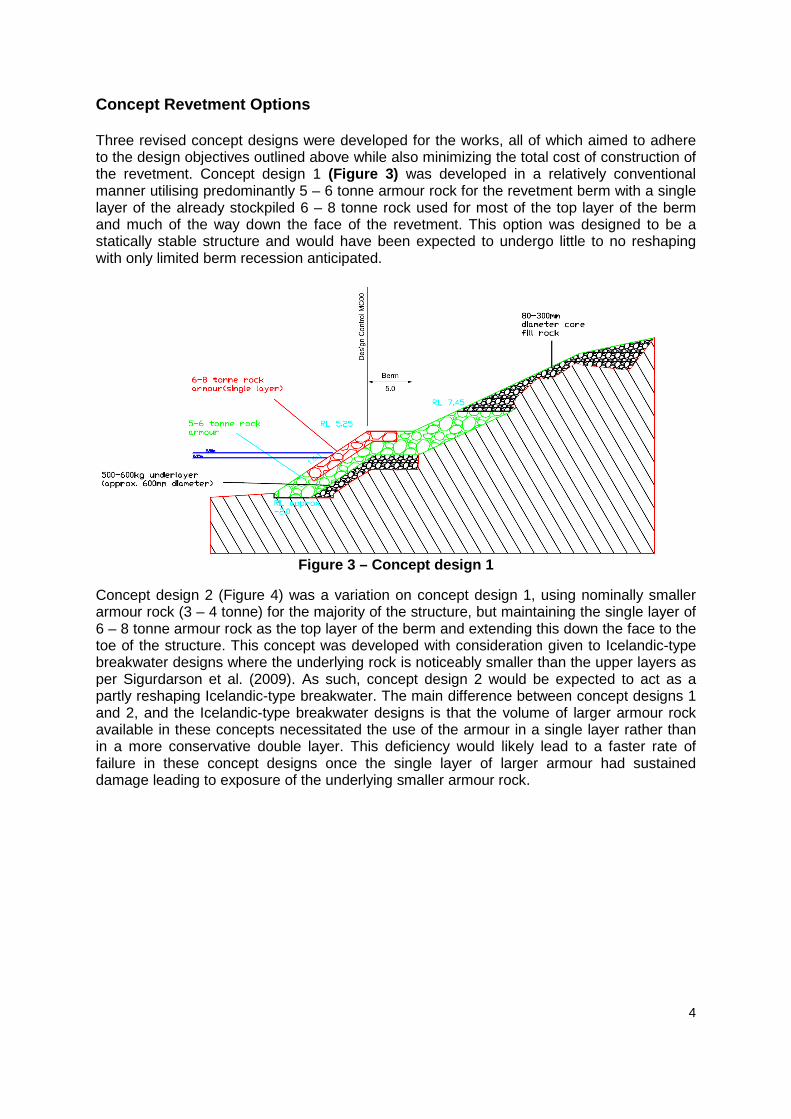
Concept Revetment Options Three revised concept designs were developed for the works, all of which aimed to adhere to the design objectives outlined above while also minimizing the total cost of construction of the revetment. Concept design 1 (Figure 3) was developed in a relatively conventional manner utilising predominantly 5 – 6 tonne armour rock for the revetment berm with a single layer of the already stockpiled 6 – 8 tonne rock used for most of the top layer of the berm and much of the way down the face of the revetment. This option was designed to be a statically stable structure and would have been expected to undergo little to no reshaping with only limited berm recession anticipated.
Figure 3 – Concept design 1
Concept design 2 (Figure 4) was a variation on concept design 1, using nominally smaller armour rock (3 – 4 tonne) for the majority of the structure, but maintaining the single layer of 6 – 8 tonne armour rock as the top layer of the berm and extending this down the face to the toe of the structure. This concept was developed with consideration given to Icelandic-type breakwater designs where the underlying rock is noticeably smaller than the upper layers as per Sigurdarson et al. (2009). As such, concept design 2 would be expected to act as a partly reshaping Icelandic-type breakwater. The main difference between concept designs 1 and 2, and the Icelandic-type breakwater designs is that the volume of larger armour rock available in these concepts necessitated the use of the armour in a single layer rather than in a more conservative double layer. This deficiency would likely lead to a faster rate of failure in these concept designs once the single layer of larger armour had sustained damage leading to exposure of the underlying smaller armour rock.

5
Figure 4 – Concept design 2
Concept design 3 (Figure 5) introduces the idea of a Terminal Adaptive Revetment (TAR), an innovative design where smaller armour stones (3 – 4 tonne) are placed in front of a terminal “block” of larger armour stones (6 – 8 tonne) positioned at the rear or root of a revetment berm. This design was developed based around the desire to use the available volume of 6 – 8 tonne armour rock in a two layered format rather than as a single layer as in concepts 1 and 2. The revetment is expected to act as a partly reshaping mass armoured berm breakwater as described in Sigurdarson and van der Meer (2013).
Figure 5 – Concept design 3
Of the 3 concept designs, concept 1 was expected to be the most expensive both in terms of rock armour material costs (as it uses the larger 5 - 6 tonne armour rock) and construction costs. Constructability of both concepts 1 and 2 is to some extent more complicated than for concept 3 as the single layer berm of 6 – 8 tonne armour is more complicated to place than the terminal revetment block of armour. Larger plant may also have been required to place the 6 – 8 tonne rock down the face of the structure. Concept design 3 is also a more readily adaptable structure as the smaller armour in the rock berm is designed to adjust under major storm waves, until the root or terminal block is exposed, which triggers the need to implement the adaptation strategy and widen the berm to further dissipate wave energy within the structure. In this way, the design satisfies existing coastal protection requirements

6
without having to expend for future loading conditions until necessary (a “no regrets” strategy after Hallegatte, 2009). Based on these considerations, concept options 2 and 3 (and an adaptation strategy for each) were selected to be assessed for stability and comparative damage levels in a 2D physical model, to aid in selection of the preferred option for final design development. 2D Physical Model Testing The objectives of the 2D physical model investigation were to:
• construct a 2D model with a scale of 1:37 in MHL’s 30 m x 1 m x 1.8 m wave flume
• test four design cross-sections of the revetment (two concept designs, each with a potential future adaptation design to account for expected sea level rise)
• provide an assessment of the stability and damage for the different revetment design options
The physical model testing was carried out in MHL’s irregular wave flume facility using a model length scale of 1:37. The scale was chosen on the basis of the dimensions of the structure to be modelled, armour sizes, water levels, wave heights and the need to minimise scale effects. The bathymetry constructed for the physical model was based on nearshore hydrosurvey of the northern amphitheatre area and was the same as was previously adopted for the earlier revetment design testing undertaken for the coastal protection works. The bathymetry used was considered as a relatively conservative 2D representation of the 3D bathymetry in close proximity to the selected design cross-section.
The four cross sections tested were as shown in Figure 4 and Figure 5 as outlined above, and the potential adaptation designs for each concept as shown in Figure 6 and Figure 7 . Each cross section was constructed from a toe level of -2m AHD up to the crest levels of 7.45 m AHD for concept 3, and up to 6.50 m AHD for concept 2. The main differences between the different design cross sections include:
• the volume and configuration of 6-8 tonne armour rock, with concept 3 using slightly less rock but a two layer terminal configuration, while concept 2 uses slightly more rock in a single layer configuration over the entire front face and part of the berm; and
• adaptation for concept 3 uses additional 3-4 tonne rock to extend the berm width, while adaption for concept 2 used smaller 1-3 tonne rock in front of the 6-8 tonne primary armour.
The model was constructed with the core material covered by a layer of plastic and a geotextile fabric to reduce the permeability of the core and hence decrease the stability of the model armour while increasing wave runup and overtopping relative to that expected in the prototype (conservative). All armour units were randomly placed on the structure in the configurations shown in Figure 4 to Figure 7 . Narrow or single-sized armour stone gradings were used with D85/D15 approximately equal to 0.9 for all armour rock distributions.
Throughout testing the wave climate was recorded by 3 deepwater capacitance probes and one probe in shallow water (approximately 45m from the structure). All test durations were for 2000 waves which is over 6 hours duration in prototype for 12 second and 14 second period waves. Testing was undertaken for the water level and wave conditions as shown in Table 1 .
7
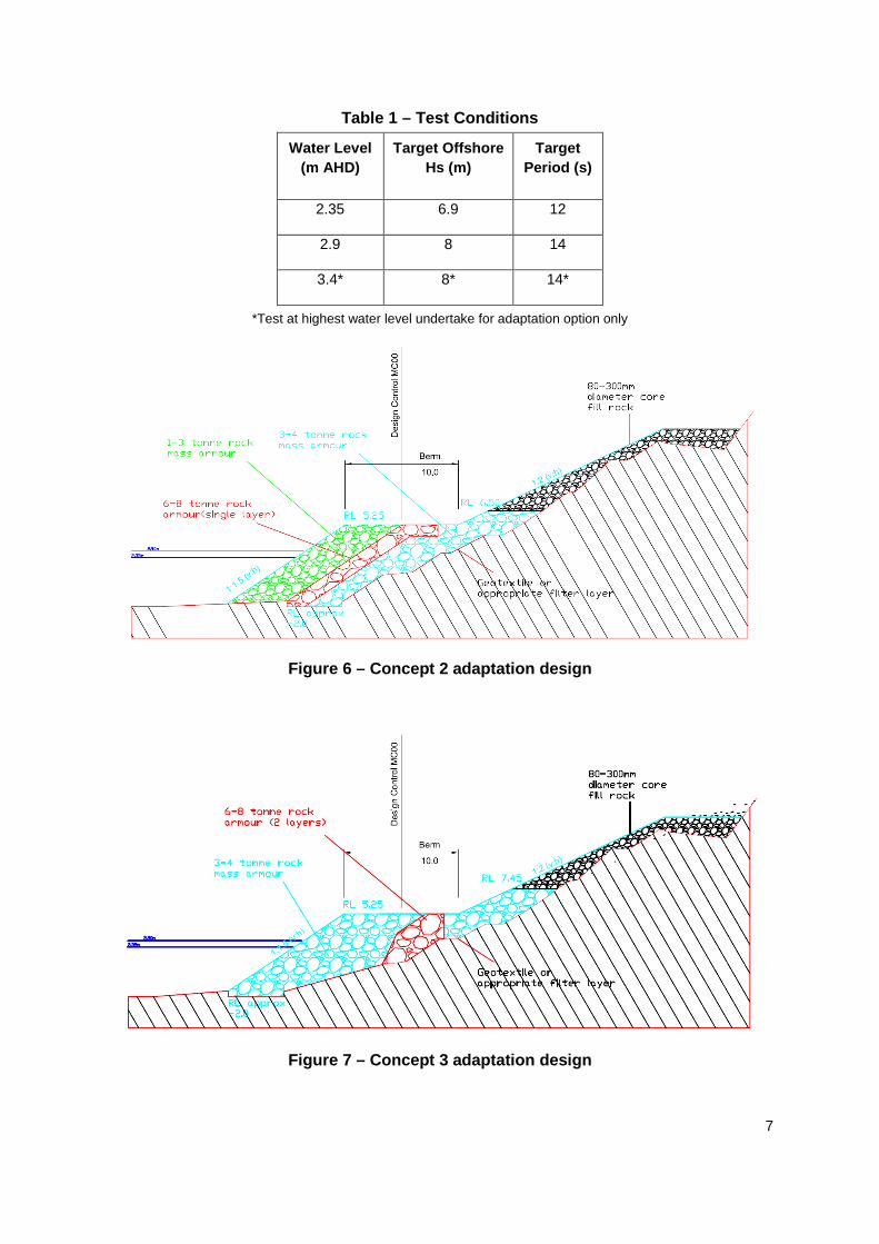
Table 1 – Test Conditions
Water Level (m AHD)
Target Offshore Hs (m)
Target Period (s)
2.35 6.9 12
2.9 8 14
3.4* 8* 14*
*Test at highest water level undertake for adaptation option only
Figure 6 – Concept 2 adaptation design
Figure 7 – Concept 3 adaptation design

8
The offshore wave climate recorded during testing at the 3 deepwater wave probes in the model closely matched the targeted offshore wave conditions as described in Table 1 . However, it was noted that the wave heights recorded at the nearshore probe (45m from the structure) were generally lower than the nearshore breaking wave heights estimated by numerical modelling of the area undertaken by Lawson & Treloar in 2004 (estimated Hs = 4.6m for 100 year ARI in numerical model vs. recorded Hs = 3.7m in model). The difference between the nearshore wave height results could be attributable to 3 dimensional effects not represented in the 2D wave flume model, even with the adopted conservative representation of the 3D bathymetry. A significant amount of offshore wave breaking was observed during model testing, indicating depth limited wave breaking conditions at the structure which may not have been well represented in the previous numerical modelling.
Estimates of the level of damage observed for each of the design cross sections at the completion of testing were made with damage defined in terms of the percentage of armour units that were displaced by a distance of greater than one armour unit diameter. Typical levels of damage that are considered acceptable for statically stable revetments are less than 5%, however higher levels of damage can be tolerated for dynamically stable mass armour structures (being of three or more armour layers thick) as represented by concept design 3. Observed damage levels were 0-1% and approximately 7% for concept 2 and its associated adaptation strategy. Observed damage levels were approximately 1-3% for concept 3 and its associated adaptation strategy. All cross sections tested experienced damage that can be considered to be within tolerable levels under the design test conditions achieved. Rates of overtopping were negligible for all test at the 7.45 m AHD crest level and only minor rates were measured for the 6.5 m AHD crest including under projected SLR conditions.
Each cross-section tested can be classified as one of the four main types of berm breakwater described in Sigurdarson and van der Meer (2013). Table 2 gives this classification which is based on armour stability number.
Table 2 – Berm Breakwater Classification (after Sig urdarson and van der Meer (2013))
Concept Design
Stability Number
(Hs/∆Dn50) Classification
Concept 1 1.6-2.0 Partly reshaping mass armoured berm breakwater
Concept 1 Adaptation
1.7-2.2 Partly reshaping mass armoured berm breakwater
Concept 2 1.3-1.7 Hardly reshaping Icelandic-type berm breakwater
Concept 2 Adaptation
2.1-2.6 Partly reshaping to reshaping mass armoured berm breakwater

9
Following testing, damage profiles were measured to provide an indication of any reshaping of the initially constructed revetment profiles. No significant reshaping of the profile was observed, however a small amount of berm recession was measured which was consistent with the level of berm recession that would be expected based on the equations given in Sigurdarson and van der Meer (2013). The berm width for the final design and adaptation strategy was defined based on both the maximum recession measured during the 2D model testing and on the maximum predicted recession from the berm breakwater design theory using the higher wave heights as reported for the numerical modelling. Figure 8 and Figure 9 show before and after testing photographs of the concept 2 and 3 models. Figure 10 and Figure 11 show waves breaking on all four cross-sections during testing.
Figure 8 – Concept 2 before and after testing (0-1% damage)
Figure 9 – Concept 3 before and after testing (1% d amage)
Figure 10 – Waves breaking on concept 2 during test ing of base design (LHS) and adaptation strategy (RHS)

10
Figure 11 – Waves breaking on concept 3 during test ing of base design (LHS) and adaptation strategy (RHS)
Based on the 2D model testing results and qualitative comparisons between the two concepts, both of the design options tested were considered as viable concepts for final design development. Both design concepts are relatively unconventional (i.e. not employing a statically stable conventional 2 layers of primary armour), although each have been shown to be stable and provide effective coastal protection under the test conditions. In consultation between RMS and MHL the preferred options for final design development was the TAR structure of concept 3, based on the expected construction cost savings compared to concept 2, the indicated stability of the 3-4 tonne mass armour with a terminal 6-8 tonne 2 layer armour wedge at the rear of the berm and the better constructability compared with option 2.
Although the concept designs were shown to be stable under the test conditions, some uncertainty remains as to the armour stability under larger breaking wave conditions which were indicated from numerical modelling previously undertaken by Lawson & Treloar 2004. For the achieved model significant wave heights of between 2.8m and 3.7m near the structure, the estimated berm recession for the 3-4 tonne rock armour based on analytical methods was 0.5m to 2.6m (0.4 to 2.5 armour units). The measured model recession was slightly less than these estimated analytical values. Adopting the higher nearshore wave conditions of 4.2m to 4.6m based on Lawson & Treloar’s numerical model (albeit invalidated), an estimated analytical berm recession of between 5m and 6m was calculated for the TAR berm concept. With the initial berm width at 5m (backed by the 6-8 tonne terminal armour block), this would result in the need for the structures’ adaptation strategy to be implemented should those wave conditions be experienced at the structure. Given the relatively mild offshore bathymetry of the study area, nearshore wave heights of 4.2m to 4.6m could not be achieved in the 2D model due to breaking offshore, but may nevertheless be possible due to 3D effects, particularly under future sea level rise projections.
The results show that the TAR concept design has been demonstrated to be sufficiently stable to withstand the adopted present day sea level and design wave conditions as tested in the 2D physical model. Due to some remaining uncertainty regarding the nearshore breaking wave heights at the structure and their expected potentially significant impact on armour stability, a 3 dimensional (3D) physical model has been recommended to be undertaken to verify and potentially further refine the proposed future adaptation strategy for the revetment.
It is noted that numerical models rely on many empirical parameters to account for nearshore and some 3D effects and may be unreliable in shallow water where breaking and

11
other focusing effects may have not been validated from field observations. The recommended 3D modelling would allow confirmation of nearshore design wave conditions, taking into account the combined effects of refraction, diffraction, shoaling and breaking, including the potential for wave focusing that may be responsible for the indicated higher nearshore wave climate from the earlier numerical model study. This would provide further confidence in the recommended TAR design concept and its future adaptation strategy’s adequacy to account for future sea level rise.
Final Terminal Adaptive Revetment (TAR) Design Following the 2D model testing, RMS designers with input from MHL developed the final design and adaptation strategy for the revetment as shown in Figure 12 and Figure 13. MHL’s final review and certification of the proposed design was undertaken from a coastal protection and armour stability perspective noting that the geotechnical and slope stability aspects of the works have been considered separately by RMS. The proposed design is expected to perform satisfactorily from an immediate coastal hazards perspective under present day water level and design wave height conditions. The proposed adaptation design is also indicated to be effective under projected future sea level scenarios, although implementation of the adaptation measures are subject to validation of the nearshore wave conditions and further refinement of the design through the use of a 3D physical model.
Figure 12 – Final TAR design

12
Figure 13 – Final TAR adaptation strategy
Revetment Construction RMS started the TAR revetment construction on the 14th of August 2015. The construction of the revetment is currently being carried out under contract by Cleary Bros Pty Ltd who was the successful tenderers for the works. The construction plan for the works has been stepped out to make the work site both productive and safe for all workers onsite, below is the construction outline for the complete works. Stage 1: Filter rock to be installed under the 6-8 tonne armour rock, denoted by the red highlighted area in Figure 14 Stage 2: Placement of 6-8 tonne armour rock, denoted by the dark blue highlighted area in Figure 14 Stage 3: Filter rock to be installed under 3-4 tonne armour rock, denoted by the tan highlighted area in Figure 14. Stage 4: Placement of 3-4 tonne armour rock, denoted by the orange highlighted area in Figure 14. Stage 5: Filter rock to be installed under the revetment toe, denoted by the yellow highlighted area in Figure 14. Stage 6: Placement of 3-4 tonne armour rock at the revetment toe, denoted by the purple highlighted area in Figure 14. Stage 7: Filter rock to be installed on slope, denoted by the magenta highlighted area in Figure 14.

13
Stage 8: Placement of 3-4 tonne armour rock above the revetment berm, denoted by the sky blue highlighted area in Figure 14. Stage 9: Placement of core fill, denoted by the green highlighted area in Figure 14.
Figure 14– Construction Stages
Construction on site is carried out with two 50 tonne excavators, two 30 tonne dump trucks, and two 25 tonne dump trucks. The armour rock is loaded into two dump trucks at the nearby stockpile site at the Illawarra Coke Company (ICC) by the first 50 tonne excavator. Once loaded the dump trucks travel to site via Lawrence Hargrave Drive under an intermittent road closure. The dump trucks then unload the armour rock at the revetment site where the second 50 tonne excavator places the armour rock as per design with GPS tracking. The two dump truck return to the stockpile site, while the second two dump trucks loaded, pass them on the road, again under closure, and the process is continually repeated. Figure 15 shows the location of both the stockpile site and the revetment site.

14
Figure 15– Location of Construction Site.
Construction as of the end of October 2015 is approximately 60 percent completed to design and approximately 75% completed time wise, Table 3 shows the construction that has been completed along with the remaining works to be completed.
Table 3 – Construction Quantities to 31 st October 2015
Activity Completed Remaining Placement of 6-8 tonne armour rock 4459 t Nil Placement of 3-4 tonne armour rock 12,240 t 3200 t Placement of 400-600mm filter rock 3,570 t 570 t Placements of 80-300mm core rock fill 2,916 t 2,084 t 900mm ᴓ Culvert extension 15 m 45 m
Shotcrete Drainage Line Nil 125 m2
Slope Stabilisation/Rock Bolting Nil 250m2
Access track Nil 600 m2
As table 3 shows the construction is not only the revetment there is also the auxiliary works which include a culvert extension to the bottom of the revetment’s berm, slope stabilisation of the northern end of the amphitheatre, extension of a concrete drainage line, and a permanent access track for future maintenance.
15
The revetment cost to complete is estimated at a total of $4.16 million which includes both the construction and the development. This is a much better outcome than the original concept designs that were proposed at the start of the project. The savings that have occurred on this project is because of the collaboration between RMS and MHL and the willingness to investigate a flexible solution with an adaptation for the long term.
Applicability in Upgrading Existing Infrastructure The TAR revetment design is a potential applicable design philosophy for upgrading and/or repairing existing coastal structures, particularly where future required volumes of large rock may no longer be economically available. Where the footprint of the structure is of less importance, for example on the ocean rather than channel side of breakwaters, the use of smaller mass armour to create a berm in front of a statically stable terminal block of armour may prove an effective strategy in ensuring the long term stability of the overall structure. During the physical model testing a significant proportion of the incoming wave energy was dissipated throughout the berm, with waves breaking over the width of the berm as can be seen in Figure 10 and Figure 11. The addition of a berm in front of an existing structure would increase the serviceability of the structure via a reduced average rate of overtopping and would be relatively easy to repair following major storm events by “topping up” the reshaped berm with additional armour stone when required. As sea level rise inevitably creates a need to upgrade or repair existing coastal structures, the innovative TAR design thinking can provide a viable solution for managing the effects of climate change on aging existing coastal infrastructure. Conclusion MHL and RMS have successfully developed an innovative rock revetment design for the coastal protection works at Northern Amphitheatre on Lawrence Hargrave Drive. The Terminal Adaptive Revetment (TAR) structure for the site has been designed to tolerate design wave and water level conditions being exceeded through clearly defined triggers to adapt the design for projected future sea levels. The smaller rock berm (being of overall larger mass) is designed to adjust under major storm waves, until the root is exposed, which triggers the need to widen the berm and further dissipate wave energy within the structure. In this way, the structure satisfies existing coastal protection requirements without having to expend for future loading conditions until necessary (“no-regrets” strategy).
The design was developed to utilise an existing stockpile of larger rock of insufficient volume to construct the revetment, while minimising costs of sourcing and placing additional conventionally larger armour rock. The design and an adaptation strategy were shown to be effective using a two-dimensional wave flume model, saving more than $12M to the NSW government.
References Hallegatte,S. (2009), Strategies to adapt to an uncertain climate change, Global Environmental Change (19), 240-247 Lawson & Treloar Pty Ltd. (2004), Lawrence Hargrave Drive Provision of Coastal Engineering Advice, Report J2266/R2124, prepared for LHD Link Alliance

16
Sigurdarson, S., Mocke, R., Smaradon, O., Carlton, B., and Allsop, W. (2009). Development of an Icelandic-type berm breakwater for the Oakajee port project in Western Australia. Proc. ICE, Coasts, Marine Structures and Breakwaters 2009, Edinburgh, UK. Sigurdarson, S. and van der Meer, J. W. (2013). Design of berm breakwaters, recession, overtopping and reflection. Proc. ICE, Coasts, Marine Structures and Breakwaters 2013, Edinburgh, UK.