development and turbine engine performance … development and turbine engine performance ... etops...
TRANSCRIPT

DEVELOPMENT AND TURBINE ENGINE PERFORMANCE OF THREE ADVANCED RHENIUM CONTAINING SUPERALLOYS
FOR SINGLE CRYSTAL AND DIRECTIONALLY SOUDIFIED BLADES AND VANES
Robert W. Broomfield, David A. Ford, Harry K Bhangu Rolls-Royce plc
[Derby and Bristol, U.K.] 1111111111113111111111 Malcolm C. Thomas, Donald J. Frasier, Phil S. Burkholder
Allison Engine Company (Rolls-Royce plc) [Indianapolis, Indiana U.S.A.]
Ken Harris, Gary L. Erickson, Jacqueline B. Wahl Cannon-Muskegon Corporation
(SPS Technologies, Inc.) [Muskegon, Michigan U.S.A.]
ABSTRACT Turbine inlet temperatures over the next few years will
approach 1650°C (3000°F) at maximum power for the latest large commercial turbofan engines, resulting in high fuel efficiency and thrust levels approaching 445 kN (100,000 lbs). High reliability and durability must be intrinsically designed into these turbine engines to meet operating economic targets and ETOPS certification requirement
This level of performance has been brought about by a combination of advances in air cooling for turbine blades and vanes, design technology for stresses and airflow, single crystal and directionally solidified casting process improvements and the development and use of rhenium (Re) containing high y' volume fraction nickel-base superalloys with advanced coatings, including full-airfoil ceramic thermal bather coatings. Re additions to cast airfoil superalloys not only improve creep and thermo-mechanical fatigue strength but also environmental properties, including coating performance. Re dramatically slows down diffusion in these alloys at high operating temperatures.
A team approach has been used to develop a family of two nickel-base single crystal alloys (CMSX-4. containing 3% Re and CMSX0-10 containing 6% Re) and a directionally solidified, columnar grain nickel-base alloy (CM 186 LC: containing 3%
Re) for a variety of turbine engine applications. A range of critical properties of these alloys is reviewed in relation to turbine component engineering performance through engine certification testing and service experience.
Industrial turbines are now commencing to use this aero developed turbine technology in both small and large frame units in addition to aero-derivative industrial engines. These applications are demanding with high reliability required for turbine airfoils out to 25,000 hours, with perhaps greater than 50% of the time spent at maximum power. Combined cycle efficiencies of large frame industrial engines is scheduled to reach 60% in the U.S. ATS programme. Application experience to a total 1.3 million engine hours and 28,000 hours individual blade set service for CMSX-4 first stage turbine blades is reviewed for a small frame industrial engine.
NOMENCLATURE ASMET = accelerated simulated mission endurance test ATS = advanced turbine system B = boron C = carbon CGR = crack growth rate DS = directionally solidified, columnar grain
CMSX-20, CMSX-30, CMSX-40, CMSX-60, CMSX0- 10, CM 247 LC® and CM 186 LC® are registered trademarks of the Cannon-Muskegon Corporation.
LAMILLOY® is a registered trademark and CASTCOOLTI4 a trademark of Allison Engine Company.
Presented at the International Gas Turbine & Aeroengine Congress & Exhibition Orlando, Florida — June 2-June 5, 1997
This paper has been accepted for publication in the Transactions of the ASME Downloaded From: https://proceedings.asmedigitalcollection.asme.org/pdfaccess.ashx?url=/data/conferences/asmep/82057/ on 06/21/2018 Terms of Use: http://www.asme.org/about-asme/terms-of-use
OPT = durability proof testing EDAX = energy dispersive x-ray micro-analysis EFH = engine flight hours ETOPS = extended over water, twin engine certification requirements
HCF = high cycle fatigue HIP = hot isostatic pressing HP = high pressure IP = intermediate pressure ISA = International Standard Atmosphere (15°C) kN = kilo newton LCF = low cycle fatigue LW' = Larson-Miller parameter LNG = liquid natural gas MFB = machined-from-blade MW(e) = mega-watt NGV = nozzle guide vane OPR = overall pressure ratio ppm = part per million S = sulfur Si = silicon SEM = scanning electron microscope T = temperature TBC = thermal barrier coating TCP = topologically close-packed phase TEM = transmission electron microscope TEl = turbine entry temperature IF = thermal fatigue TFCLL = thermal fatigue crack initiation life TMF = thenno-mechanical fatigue TTT = transformation-time-temperature WDX = wavelength dispersive micro-analysis Zr = Zirconium [NJ = combined nitrogen [0] = combined oxygen y = gamma phase y' = gamma prime phase Astr,„, = change in mechanical strain Kr = stress concentration factor
INTRODUCTION During the last 30 years, turbine inlet temperatures have
increased by about 500°C (900°F). About 70% of this increase is due to more efficient design of air cooling for turbine blades and vanes, particularly the advent of serpentine convection and film cooling and the use of full airfoil thermal battier ceramic coatings, while the other 30% is due to improved superalloys and casting processes. The greatest advances in metal temperature and stress capability for turbine airfoils have been the result of the development of single crystal superalloy, casting process and engine application technology pioneered by Pratt and Whitney (P&W) (Gell et al., 1980).
Maximum metal temperatures approaching 1130°C (2066°F) have been flight qualified for CMSX-4 turbine blades at maximum engine power during accelerated, simulated mission endurance testing (ASMET) (Fullagar et al., 1994). Full airfoil and platform advanced thermal barrier coatings have been cerrfied for commercial turbine engine use, with the capability to increase gas temperatures by 100°C (180°F), or reduce metal temperatures commensurately to dramatically improve turbine blade life (PW, 1994).
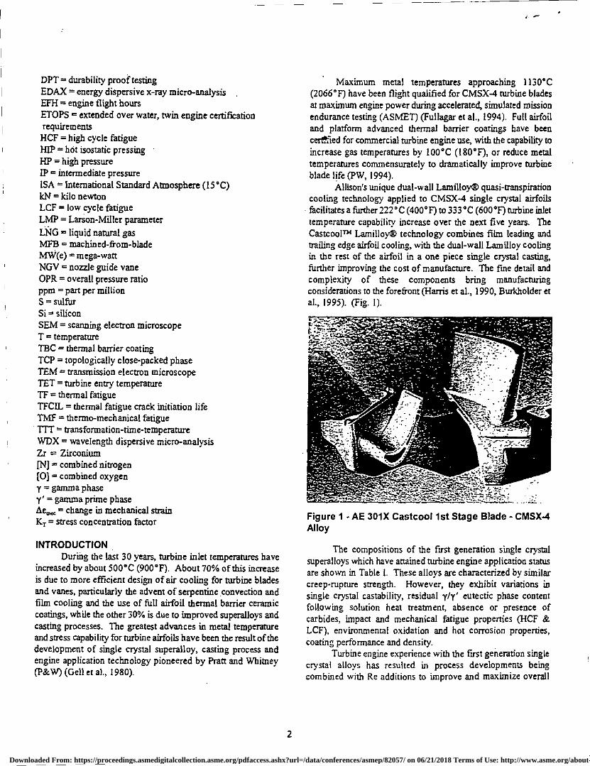
Allison's unique dual-wall Lamilloy® quasi-transpiration cooling technology applied to CMSX-4 single crystal airfoils facilitates a further 222°C (400°F) to 333°C (600°F) turbine inlet temperature capability increase over the next five years. The CastcoolTh Lamilloy® technology combines film leading and trailing edge airfoil cooling, with the dual-wall Lamilloy cooling in the rest of the airfoil in a one piece single crystal casting, further improving the cost of manufacture. The fine detail and complexity of these components bring manufacturing considerations to the forefront (Harris et al., 1990, Burkholder et al., 1995). (Fig. 1).
Figure 1 - AE 301X Castcool 1st Stage Blade - CMSX-4 Alloy
The compositions of the first generation single crystal superalloys which have attained turbine engine application status are shown in Table I. These alloys are characterized by similar creep-rupture strength. However, they exhibit variations in single crystal castability, residual y/y' eutectic phase content following solution heat treatment, absence or presence of carbides, impact and mechanical fatigue properties (HCF & LCF), environmental oxidation and hot corrosion properties, coating performance and density.
Turbine engine experience with the first generation single crystal alloys has resulted in process developments being combined with Re additions to improve and maximize overall
2
Downloaded From: https://proceedings.asmedigitalcollection.asme.org/pdfaccess.ashx?url=/data/conferences/asmep/82057/ on 06/21/2018 Terms of Use: http://www.asme.org/about-asme/terms-of-use
1
Tune, hours
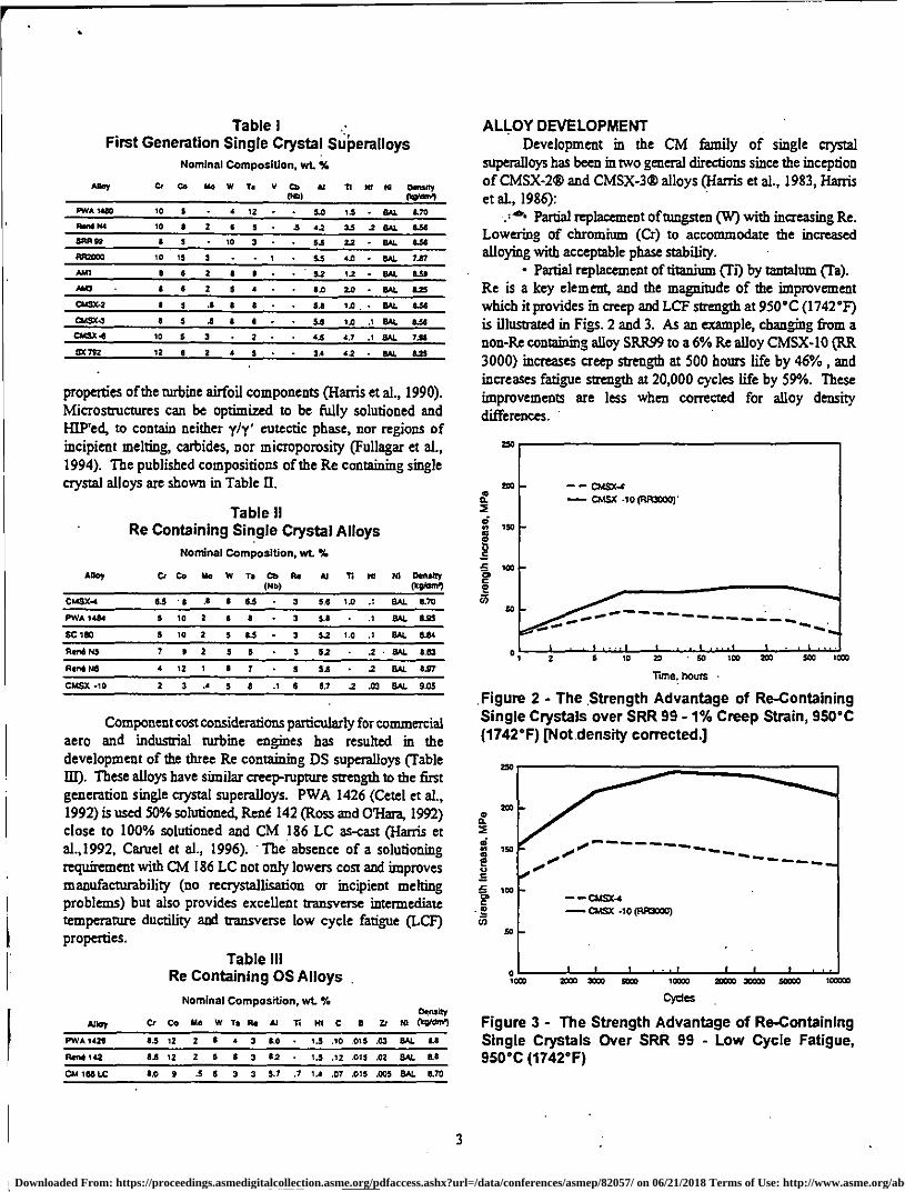
Figure 2 - The Strength Advantage of Re-Containing Single Crystals over SRR 99 - 1% Creep Strain, 950°C (1742°F) [Not density corrected.]
0, - - - - - - - - -
- ---- ..• 0 .
CIASC-4
OASX -10 (RSCIX10)
2003 X0) KW 15030
2C000 X000
.C1155
Figure 3 - The Strength Advantage of Re-Containing Single Crystals Over SRR 99 - Low Cycle Fatigue, 950°C (1742°F)
,
00030 Ic0X0
- DitSx-e CUSX .10 (RR31200)
••••••.„...
ea/ ------------ --
2 5 10
20
qr.
• 50 IX 829 SOO 1300
Table I First Generation Single Crystal Superalloys
Nominal Composition, wt. X
Ain Ce Co No W Ts V Co (N0)
AI 11 Mt id dewy Oisrent
PWA 10 5 • 4 12 • • 5.0 14 • SAL 170
RAS N4 10 I 2 6 5 • .5 4.2 33 2 SAL 1.56
EAR 99 1 3 • 10 3 - • 53 12 • SAL 1136
RR2003 10 IS 3 • • 1 • 5.5 4.0 • 841. 737
Pan 5 6 2 6 5 • • 5.2 12 - SAL 1139
NO • I 5 2 s • • • 64 2.0 • fiAL
04052 $ .e 5.5 14 641. 136
C1421143 5 3 .5 5.6 14 .1 EL4L 633
04113 10 5 3 44 4.7 .1 SAL 7.116
SX 7/2 II 11 2 • 3.4 42 841 1.25
properties of the turbine airfoil components (Harris et al., 1990). Microstructures can be optimized to be fully solutioned and H1P'ed, to contain neither y/y' eutectic phase, nor regions of incipient melting, carbides, nor microporosity (Fullagar et al., 1994). The published compositions of the Re containing single crystal alloys are shown in Table II.
Table II Re Containing Single Crystal Alloys
Nominal Composition, wt. %
Ann Cr Co No W Ts CO (ND)
Re 11 M1 NI Density 0022dro,
CIA3X-4 6.5 ' 9 6 6.5 3 5.6 1.0 .1 SAL 5.70
PWA 1434 5 10 2 6 9 • 3 5.6 • .1 BAL ILO
Sc 100 5 10 2 $ 0.5 - 3 5.2 1.0 .1 RR. 854
Rerd 5/5 7 5 2 $ 5 • 3 62 .2 MAL 3.33
Rend $6 • 12 1 6 7 • 5 54 • .2 SAL 6.97
CMS% -10 2 3 .4 5 3 .1 6 S.? .2 .03 SAL 935
Component cost considerations particularly for commercial aero and industrial turbine engines has resulted in the development of the three Re containing DS superalloys (Table 131). These alloys have similar creep-rupture strength to the first generation single crystal superalloys. PWA 1426 (Cetel et aL, 1992) is used 50% solutionecl, Rene 142 (Ross and O'Hara, 1992) close to 100% solutioned and CM 186 LC as-cast (Harris et al.,1992, Camel et al., 1996). ' The absence of a solutioning requirement with CM 186 LC not only lowers cost and improves manufacturability (no recrystallisation or incipient melting problems) but also provides excellent transverse intermediate temperature ductility and transverse low cycle fatigue (LCF) properties.
Table III Re Containing DS Alloys .
Nominal Composition, wt. Ti
Alloy Cr Co Mo w to Re Al Ti 141 C a Zr Noway
w 0021121
PV0A 1425 5.5 13 2 5 • 3 0.0 • 13 .10 .015 .03 SAL 5.6
Re4 142 6.0 12 2 5 6 3 62 - 1.5 .12 .015 .02 SAL 11.6
OA 104 LC 6.0 9 .5 8 3 3 5.7 .7 1.4 .07 .015 .005 BAL 11.70
ALLOY DEVELOPMENT Development in the CM family of single crystal
superalloys has been in two general directions since the inception of CMSX-2® and CMSX-3® alloys (Harris et al., 1983, Harris et aL, 1986):
Partial replacement of tungsten (W) with increasing Re. Lowering of chromium (Cr) to accommodate the increased alloying with acceptable phase stability.
• Partial replacement of titanium (Ti) by tantalum (Ta). Re is a key element, and the magnitude of the improvement which it provides in creep and LCF strength at 950°C (1742°F) is illustrated in Figs. 2 and 3. As an example, changing from a non-Re containing alloy SRR99 to a 6% Re alloy CMSX-10 (RR 3000) increases creep strength at 500 hours life by 46%, and increases fatigue strength at 20,000 cycles life by 59%. These improvements are less when corrected for alloy density differences.
250
Str
eng
th In
crea
se.
MP
e
IX
50
3
Downloaded From: https://proceedings.asmedigitalcollection.asme.org/pdfaccess.ashx?url=/data/conferences/asmep/82057/ on 06/21/2018 Terms of Use: http://www.asme.org/about-asme/terms-of-use

In order to understand these improvements, the distribution of Re through the microstructure has been studied in some detail on three scales: dendritic, microscopic and atomic.
DISTRIBUTION OF RHENIUM On the dendritic scale, it is well known that Re segregates
strongly to the dendrite centers and that even - alter a solution/homogenisation heat treatment, a uniform distribution is not achieved (Table IV). In the Rolls-Royce materials specifications for CMSX-4 and CMSX-I 0 (RR 3000), a different approach to measuring dendritic segregation following solution/homogenisation heat treatment has been taken. A large number of measurements of Re, W and Ta levels are made across a section perpendicular to crystal growth, and the standard deviations associated with the distributions for each element are calculated. An upper limit is set for the standard deviation for each element; the limits vary from one alloy to the other, but they do not vary by component in a given alloy. The solution/homgenisation heat treatments developed for both alloys are designed to minimise residual dendritic microsegregation and hence to maximise phase stability.
Table IV CMSX-4 ALLOY
0.25" (6.4 mm) 0 Test Bar Allison Solution/Homogenisation Heat Treatment + Double Aged
SEM-WDX Analysis (wt. °A)
Center of Interdendritic Primary Dendrite Region
Cr 5.8 5.7
Co 9.7 9.8
Ni BAL BAL
6.1 4.2
Mo .6 .7
Ti .9 1.0
Al 5.7 6.4
Re 3.7 1.9
Ta 5.0 6.5
I-If .06 .05
On a microscopic scale, the composition of the y' phase has been measured in both CMSX-4 and in an early variant of CMSX-10 (RR 3000) containing 5.3% Re (RR 2067) using EDAX micro-analysis on thin TEM foils. The alloy and y' phase compositions were as shown in Table V.
The y' compositions were much more similar to each other than were the alloy compositions, basically (Ni, Co), (Al, Ta) with some Cr, W and Ti dissolved. The Re contents in the y' were low, and so on the basis that both CMSX-4 and CMSX-I 0 (RR 3000) contain about 70 vol. % y', this implies average Re
Table V Alloy and y' phase compositions.
Co Cr Ma W Re At Ti Ta
Nominal wt. % RR2067 8.0 3.4 0.48 6.1 5.3 5.6 1.0 7.8
CMSX-4 9.7 6.5 0.6 6.4 2.9 5.6 1.0 6.5
Gamma PAM c5, vet. % RR2067 5.2 1.9 1.0 5.6 1.9 6.1 1.25 11.4
CMSX-4 6.1 2.7 055 5.75 1.4 6.2 1.4 10.7
Gamma Prime (75, at.% RR2067 5.5 2.3 0.6 1.9 0.65 14.1 1.6 3.9
CMSX-4 6.4 3.2 0.35 1.9 0.45 14.2 1.75 3.6
levels in the y phase of about 6 wt. % and 13% (by weight) respectively in the two alloys. It is not surprising therefore, that under conditions where dislocation movement is confined to the y phase, Re additions are very powerful strengtheners.
Atom-probe micro-analyses of Re containing .modifications of PWA 1480 and CMSX-2 alloys reveal the occurrence of short range order in the y matrix (Blavette et al. 1986 , Blavette et al., 1988). Small Re clusters (approximately • 1.0 Ann in size) are detected in the alloys. The Re clusters act as efficient obstacles to dislocation movement in the y matrix channels compared to isolated solute atoms in solid solution and thereby play a significant role in improving alloy strength. The benefits of Re to mechanical properties are seen in situations where dislocation movement within the y phase matrix channels is controlling. Where dislocations pass readily through both y and y' phases, the strength advantage is smaller. Dislocations travel mainly within the y matrix channels at higher temperatures >850°C (1562°F). A consistent benefit for CMSX-4 for example is seen in tensile strength, creep and stress-rupture strength over the temperature range 850-1050°C (1562-1922°F) where the temperature capability advantage is at least 30°C (54°F) over SRR 99.
Further work on the distribution of Re on the atomic scale is being undertaken at Oxford University using atom-probe micro-analysis. In filly heat-treated CMSX-10 (RR 3000), a pronounced buildup of Re has been observed adjacent to the y' particles - as one might expect since Re is a slow-diffusing element which is rejected by the growing y' (Fig. 4).
r phase 7 phase
Al
Figure 4 - Re Distribution Across y and y' Phases CMSX-10 (RR 3000)
4
Downloaded From: https://proceedings.asmedigitalcollection.asme.org/pdfaccess.ashx?url=/data/conferences/asmep/82057/ on 06/21/2018 Terms of Use: http://www.asme.org/about-asme/terms-of-use

u5
0
OA
0.7
0.0
32300 31000 05
vcco 29030 MOO 30000
Larson - Miller Parameter
12
1.1
1.0
INFLUENCE OF Re UPON SELECTED PROPERTIES The influence of Re is all-pervasive in this class of
superalloy, but five areas have been selected: stability of y' at high temperatures, effect of Re distribution upon primary creep behavior, oxidationaoerformance, thermal fatigue, and finally LCF properties.
Stability of v' . y' stability is important in terms of resistance to coarsening
and re-solutioning of y' during coating or brazing operations. CMSX-4 has good performance in this respect, as indicated by a recent paper (Miglietti and Pennefather, 1996). These workers measured y' size following a wide range of brazing/diffusion heat treatments up to 1240°C (2264°F). These times and temperatures have been combined via the Larson-Miller parameter (LMP) (Fig. 5); there is steady y' growth up to a LMP of 30,000, but much faster growth thereafter. The 30,000 value conesponds for instance to 3 hours at 1190°C (2174°F) (atypical brazing condition). It is interesting to note that the resistance to y' coarsening appears to be improved by the 1140°C (2085°F) intermertivf. age used for CMSX-4. As-solution-treated CMSX-4 was soaked for various times and temperatures by Roan (1996), and in this condition, 3 hours at 1190°C (2174°F) caused significant dissolution of the cubic y'. Quite probably the Re "wall" at the y/y' interface, observed in the atom-probe work, is effective in restricting growth and dissolution of the y'.
Figure 5 - Gamma Prime Size in CMSX-4 vs. Soaking Condition, hrs/°C
y' stability is further improved in the 6% Re alloy CMSX-10 (RR 3000). During creep tests at 1175°C (2147°F) a stable y' rafted structure developed in a few hours, and was still stable after 60 hours testing (Fig. 6).
Figure 6 - Rafted y/y 1 Structure in CMSX-10 (RR 3000) after 1% creep strain in 60 hours at 1175°C (2147°F)
Primary Creel, Behavior During the development of CMSX- 10 (RR 3000) it was
noted that the magiitude of primary creep varied with the casting source. Times to rupture were fairly consistent, but the times to 1% creep strain on samples from the "good" source were between two and four times as long as those from the "worst" source. When the standard homogeneity check was carried out, a good correlation Was observed between homogeneity and creep life; the standard deviation for Re . was 1.23% in the worst samples, falling to 0.6% in the best ones. The casting source with the highest thermal gradient and solidification rate gave the lowest standard deviation for Re. A proposed explanation for this effect is as follows:
In cast and heat treated single crystals, the dislocations are concentrated in interdendritic regions (Pollack and Argon, 1992). As deformation occurs, these dislocations multiply and spread throughout the structure. In more heavily segregated test pieces, the dislocation motion through the y matrix channels at the start of the 1080°C (1975°F) test (ie., primary creep) will therefore occur in regions low in rhenium, and hence low in creep strength. A rapid rate of primary creep would therefore be expected. In the most segregated sample referred to above, it was estimated that the weakest 10% of the structure contained only 3.0 - 4.3% Re and 4.5% W, so might be comparable with homogeneous CMSX-4 with 2.9% Re + 6.4% W. Once dislocations have spread throughout the structure the overall creep rate will be a function of the average composition of the alloy, hence segregation has less effect upon the stress-rupture life.
Oxidation.Behavioi The oxidation performance of 3% and 6% Re containing
single crystal alloys at 1100°C (2012°F) for instance, is remarkably good bearing in mind the low Cr content of these materials. Normally, in cast superalloys with 5.5 - 6.2%
5
Downloaded From: https://proceedings.asmedigitalcollection.asme.org/pdfaccess.ashx?url=/data/conferences/asmep/82057/ on 06/21/2018 Terms of Use: http://www.asme.org/about-asme/terms-of-use
1500 2600
Time (MOSS)
ISO) 1010 1503 503
-o- 1151 -San
-go- psi -SEP KAI
-4.- 551 - ASP Akaft
IS
JP-5 Rai Or*: 60 Mona Rame Dwell
Weiss Coll *kr 131151
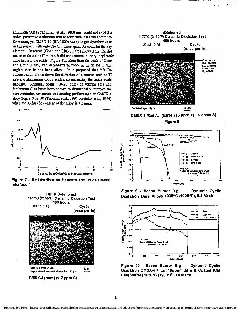
aluminum (Al) (Strangman, et al., 1980) one would not expect a stable, protective a alumina film to form with less than about 8% Cr present, yet CMSX-10 (RR 3000) has quite good performance in this respect, with only 2% Cr. Once ;pin, Re could be the key element. Research (Chen and Little, 1995) showed that Re did not enter the oxide film, but it did concentrate in the y' depleted ,- zone beneath the oxide. Figure 7 is taken from the work of Chen and Little (1995) and demonstrates mice as much Re in this region than in the base alloy. It is proposed that this Re concentration slows down the diffusion of elements such as Ti into the aluminium oxide scales, so increasing the oxide scale stability. Residual ppms (10-20 ppm) of yttrium (Y) and lanthanum (La) have been shown to dramatically improve the bare oxidation resistance and coating performance on CMSX-4 alloy (Fig. 8,9 & 10) (Thomas, et al, 1994, Korinko, et al, 1996) when the sulfur (S) content of the alloy is <2 ppm.
Ato
mic
% R
e
3
is
2
1.5
0 ro IS 20
25
Distance from Oxide/Metal Interface, microns
Figure 7 - Re Distribution Beneath The Oxide! Metal Interface
HIP & Solutioned 1177°C (2150°F) Dynamic Oxidation Test
450 hours Mach 0.45 Cyclic
(once per hr)
Depleted layer 94 WO
20sm Depth of wide:ion/diffusion voids 182 pm
)--f
CMSX-4 (bare) (<2 ppm S)
Solutioned 1177°C (2150°F) Dynamic Oxidation Test
450 hours Mach 0.45
Cyclic (once per hr)
Depleted faYor 10 srfl
20 om II
CMSX-4 Mod A. (bare) (15 ppm Y) (< 2ppm S)
Figure 8
Figure 9 - Becon Burner Rig Dynamic Cyclic Oxidation Bare Alloys 1038°C (1900°F), 0.4 Mach
Figure 10 - Becon Burner Rig Dynamic Cyclic Oxidation CMSX-4 + La [16ppm] Bare & Coated [CM Heat V8614] 1038°C (1900°F) 0.4 Mach
r
.—Continucas. Min. *lumina Vg2 0i wide scale Slyer Son tack
6
Downloaded From: https://proceedings.asmedigitalcollection.asme.org/pdfaccess.ashx?url=/data/conferences/asmep/82057/ on 06/21/2018 Terms of Use: http://www.asme.org/about-asme/terms-of-use

'NYC (INV")
wart otorri
canes. • sa. se • ISIS mre Corn I Hat 170C11.10C • lb in f nrc 110:071 AC MAO. it
.070•0 "l DP.
mire morn
.64,0731 Waal Wall WS. MS. MM. NHS. VaVa WZR,V011,
NW& Sit nal. Nail. ■1561
1 1 I I I 1111 1 1 1 1 11111
1 1 1 1 1 III
It has also been found that La gives improved control of its ppm chemistry in the single crystal casting process compared to Y. It is now also known that the La and Y tie-up the residual S as very stable sulfides. The latest burner rig data indicates ppm combinations of La + Y may give the best results at 1038 ° C (1900 ° F) and 1093 °C (2000 °F) test temperatures. S wealcens the strong Van der Waal's bond between the alumina scale and the base alloy.
Phase Stability One aspect of critical importance in these high Re
superalloys is the metallurgical stability, ie., the rate of formation . of topologically-close packed phases (TCPs). These are not present significantly in the practical use of CMSX-4, but in CMSX-10 (RR 3000) the operating conditions of components have to be carefully considered against the TTT curve for formation of these phases. CMSX-4 shows continuing linear relationships for log stress to log stress-rupture life, (Fig. 11) with no fall-off due to excessive TCP phase formation, out to the extent of current testing: 5,600 hrs. at 1121 ° C (2050 °E), 12,400 hrs. at 1093 °C (2000 ° F), and 17,000 hrs. at 982 ° C (1800 °F). • The composition of these TCP phases has been established by Chen and Little (1995) as shown in Table VI.
1030
500
• 100 0. 2
50
10 10 50 103 SOO 1003
5000 1COSO
Rupture Lila 000 --00
Figure 11 - Stress - Rupture CMSX-4 Alloy (Average 001)
Table VI TCP Phases Nit %)
Ni Co Cr Mo W Re Al Ti
CMSX-4 20 8 9 2 28 28 1 4 CMSX -10 (RR3000) 30 2 6 1 10 44 2 5
Unlike the y' phase referred to earlier, the compositions of the TCP phases formed are clearly different in the two alloys. They are both basically .Ni-Cr-W-Re, but the Re: W ratio in particular is much higher in CMSX-10 (RR 3000), reflecting the basic chemistry differences of the two alloys.
The important factor from a turbine engine performance viewpoint is of course the effect which these TCP phaq•s have upon mechanical properties. Some TCP phases particularly in multi-grain cast superalloys have a marked embrittling effect, but these do no; their effect is Z.:educe creep strength when a certain volume fraction is formed by concentrating Re and W into. an ineffective form, in effect de-alloying the material. During the CMSX- I0 (RR 3000) development programme, the amount of TCP phase was estimated by a point - counting technique. The point was counted if it fell either on a TCP needle or on its y' envelope, so in effect the proportion of the structure that was other than the normal y + y' was measured. To give one example, unstressed exposure of CMSX-10 (RR 3000) for 250 hours at 1100 °C (2012 ° F) gave an area fraction of TCP's of 5%, but this had no deleterious effect upon the impact strength, high or low cycle fatigue strength . of the alloy. A substantial deviation in creep strength was only seen when the area fraction of TCFs approached 20%. In that condition, the creep elongation was still in the range of 13 to 18%, confirming these TCP's do not have an embrittling effect upon this single crystal alloy at this area fraction level.
Thermal Fatigue (TFI The thermal fatigue behavior of CMSX-4 and SRR99 has
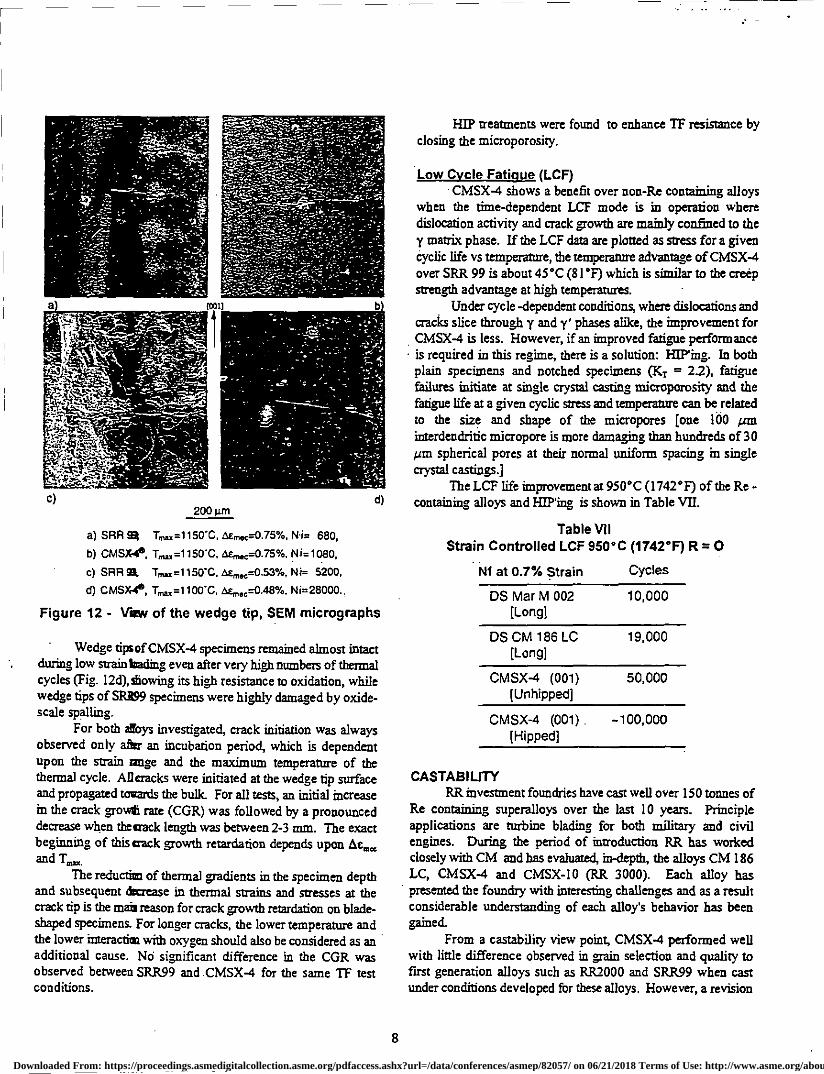
been investigated on blade-shaped single edge wedge specimens (Meyer - Olbersleben, et al., 1992, Meyer - Olbersleben, et al, 1996). The strain was measured at the wedge tip of the IF specimens. Temperature-mechanical strain cycles with different mean strain values and strain ratios were obtained. The strain distribution on the edge was presented. Further, TF crack initiation life and total life depend on the strain cycle, which itself is temperature, gradient dependent On the basis of TF stain measurements, a new TMF cycle was introduced. An integrated approach for TF and TNT investigations was proposed. Preliminary investigations show that under the test conditions used, TF cycling is more damaging than IMF. IT crack initiation mechanisms for both superalloys were identified. Finally, the higher TF crack . initiation resistance of CMSX-4 is explained by its higher oxidation resistance combined with a higher mechanical strength of its y'-depleted zone and y/y'- microstructure (Fig. 12) (Meyer - Olbersleben, 1996).
In SR1299 and CMSX-4, residual cast microporosity on the wedge tip led to stress concentration. For both alloys under high strain loading, cracks always initiate on these porosities at the specimen surface, Fig. 12a + b.
Under low strain loading the number of thermal cycles (NO to crack initiation is much higher. Nevertheless, the same mechanism of crack initiation on microporosities was observed for CMSX-4, Fig. 12d. For SRR99, a complex mechanism of oxidationJspallation/reoxidation combined with the effect of the residual cast microporosity was identified as the crack initiation mechanism, Fig. 12.
7
Downloaded From: https://proceedings.asmedigitalcollection.asme.org/pdfaccess.ashx?url=/data/conferences/asmep/82057/ on 06/21/2018 Terms of Use: http://www.asme.org/about-asme/terms-of-use
c) d) 200 WC
a) SRR 9311 Inn =1150t, as-mec--0.75%, N1.1= 680,
b) CMSX441., Tran =1150t, M=1080,
c) SRR 93, Trnax =1 1 50 t Umn=0.53%, Ni= 5200,
d) CMSX4S, Tnn =1100t, ae,“=0.48%, M=28000..
Figure 12 - View of the wedge tip, SEM micrographs
• Wedge tipsof CMSX-4 specimens remained almost intact during low strain loading even after very high numbers of thermal cycles (Fig. 12d), showing its high resistance to oxidation, while wedge tips of SRR99 specimens were highly damaged by oxide-scale spalling.
For both afoys investigated, crack initiation was always observed only after an incubation period, which is dependent upon the strain range and the maximum temperature of the thermal cycle. Alleracks were initiated at the wedge tip surface and propagated towards the bulk For all tests, an initial increase in the crack gowt rate (CGR) was followed by a pronounced decrease when thetrask length was between 2-3 ram. The exact beginning of this crack growth retardation depends upon Ac me, and Tran
The reduction of thermal gradients in the specimen depth and subsequent decrease in thermal strains and stresses at the crack tip is the mais reason for crack growth retardation on blade-shaped specimens. For longer cracks, the lower temperature and the lower interactias with oxygen should also be considered as an additional cause. No significant difference in the CGR was observed between SRR99 and CMSX-4 for the same TF test conditions.
HIP treatments were found to enhance IT resistance by closing the microporosity.
Low Cycle Fatigue (LCF) CMSX-4 shows a benefit over non-Re containing alloys
when the time-dependent LCF mode is in operation where dislocation activity and crack growth are mainly confined to the y matrix phase. If the LCF data are plotted as stress for a given cyclic life vs temperature, the temperature advantage of CMSX-4 over SRR 99 is about 45°C (81°F) which is similar to the creep strength advantage at high temperatures.
Under cycle -dependent conditions, where dislocations and cracks slice through y and y' phases ace, the improvement for CMSX-4 is less. However, if an improved fatigue performance
• is required in this regime, there is a solution: H1P'ing. In both plain specimens and notched specimens (KT = 22), fatigue failures initiate at single crystal casting microporosity and the fatigue life at a given cyclic stress and temperature can be related to the size and shape of the micropores [one 100 an interdendritic micropore is more damaging than hundreds of 30 jam spherical pores at their normal uniform spacing in single crystal castings.]
The LCF life improvement at 950°C (1742°F) of the Re - containing alloys and HIP'ing is shown in Table VII.
Table VII Strain Controlled LCF 950°C (1742°F) R = 0
NI at 0.7% Strain Cycles
DS Mar M 002 10,000 [Long]
DS CM 186 LC 19,000 [Long]
CMSX-4 (001) 50,000 [Unhipped]
CMSX-4 (001) -100,000 [Ripped]
CASTABILITY RR investment foundries have cast well over 150 tonnes of
Re containing superalloys over the last 10 years. Principle applications are turbine blading for both military and civil engines. During the period of introduction RR has worked closely with CM and has evaluated, in-depth, the alloys CM 186 LC, CMSX-4 and CMSX-10 (RR 3000). Each alloy has presented the foundry with interesting challenges and as a result considerable understanding of each alloy's behavior has been gained.
From a castability view point, CMSX-4 performed well with little difference observed in gain selection and quality to first generation alloys such as RR2000 and SRR99 when cast under conditions developed for these alloys. However, a revision
8
Downloaded From: https://proceedings.asmedigitalcollection.asme.org/pdfaccess.ashx?url=/data/conferences/asmep/82057/ on 06/21/2018 Terms of Use: http://www.asme.org/about-asme/terms-of-use
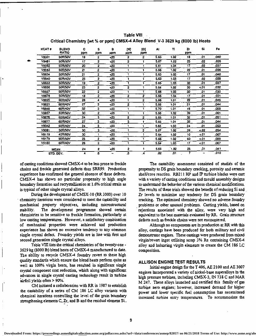
Table VIII Critical Chemistry (wt To or ppm] CMSX-4 Alloy Blend V-3 3629 kg (8000 lb) Heats
a.
HEAT# BLEND RATIO PPIll ppm PPm PPm
(0) Pan
Al 11 Zr ppm
Si Fe
V8331 SOR/SOV 18 2 <20 2 2 5.63 1.02 18 .01 .040 V8481 50FU50V 17 2 <20 2 1 5.67 1.02 25 .02 .026 V8562 50R150V 20 2 <20 1 1 5.61 1.04 17 .02 .037 V8563 50R150V 21 2 <20 1 1 5.66 1.02 22 .01 .036 V8634 50R/50V 21 2 <20 1 1 5.63 1.02 17 .01 .040 V8640 60R/40V 25 2 <20 1 1 5.63 1.03 17 .02 .038 V8653 50FUSOV 19 2 <20 1 1 5.65 1.03 32 .01 .037 18656 50R/50V 23 2 <20 2 1 5.64 1.02 30 <.01 .032 V8657 505/SOV 22 2 <20 1 1 5.66 1.03 30 .01 .030 V8678 505/SOV 18 2 <20 2 2 5.66 1.04 17 .01 .031 V8820 605/40V 28 4 <20 1 2 5.66 1.01 22 .01 .045 V8821 60R/40V 27 3 <20 2 1 5.68 1.01 21 .01 .044 V8848 60(9140V 32 3 <20 1 1 5.70 1.01 18 .01 .059 V8857 505ISOV 30 2 <20 1 1 5.68 1.02 39 .01 .061 V8876 60R/40V 24 3 <20 2 2 5.65 1.01 32 .01 .051 V8877 60F140V 27 3 <20 3 1 5.65 1.01 32 .01 .044 V9042 60R/40V 24 3 <20 1 1 5.65 1.03 24 .01 .053 V9081 SOFVSOV 30 3 <20 1 2 5.67 1.02 39 <.02 .054 V9119 40R/60V 30 1 <20 1 1 5.64 1.02 10 <.01 .067 V9179 soRroov 25 2 <20 1 1 5.66 1.02 60 <.01 .089 V9180 60R/40V 26 3 <20 1 1 5.64 1.03 17 <.01 .067
MEAN 24 2 <20 2 1 5.65 :1.02 25 .01 .041
STD. OEV. .6 .6 .4 .02 .01 7 .010
of casting conditions showed CMSX-4 to be less prone to freckle chains and freckle generated defects than SRR99. Production experience has confirmed the general absence of these defects. CMSX-4 has shown no particular propensity to high angle boundary formation and recrystallisation at 1.6% critical strain as is typical of other single crystal alloys.
During the development of CMSX-10 (RR 3000) over 10 • chemistry iterations were considered to meet the testability and mechanical property objectives, including microstructural stability. The development programme showed certain chemistries to be sensitive to freckle formation, particularly at low casting temperatures. However, a satisfactory combination of mechanical properties were achieved and production experience has shown no excessive tendency to any common single crystal defect. Foundry yields are in line with first and second generation single crystal alloys.
Table VIII lists the critical chemistries of the twenty-one - 3629 kg (8000 lb) blend heats of CMSX-4 manufactured to date. The ability to recycle CMSX-4 foundry revert to these high quality standards which ensure the blend heats perform quite as well as 100% virgin heats, has resulted in significant single crystal component cost reduction, which along with significant advances in single crystal casting technology result in turbine *airfoil yields often > 90%.
CM initiated a collaboration with RR in 1987 to establish the testability of a series of CM 186 LC alloy variants with chemical iterations controlling the level of the wain boundary strengthening elements C, Zr, and B and the residual element Si..
The testabilitv assessment consisted of studies of the propensity to DS grain boundary cracking, porosity and ceramic shell/core reaction. RB211 HP and IP turbine blades were cast with a variety of casting conditions and mould assembly designs to understand the behavior of the various chemical modifications. The results of these trials showed the benefit of reducing Si and Zr levels to minimise any tendency for DS grain boundary cracking. The optimised chemistry showed no adverse foundry problems or other unusual problems. Casting yields, based on rejections associated with the alloy, were very high and equivalent to the best materials evaluated by RR Grain structure defects such as freckle chains were not encountered.
Although no components are in production at RR with this alloy, castings have been produced for both military and civil demonstrator engines. These castings were produced from mixed virgin/revert ingot utilising scrap 3% Re containing CMSX-4 alloy and balancing virgin elements to create the CM 186 LC composition.
ALLISON ENGINE TEST RESULTS Initial engine desiga for the T406, AE 2100 and AE 3007
engines incorporated a variety of nickel-base superalloys in the high pressure turbines, including CMSX-3, IN 738 C and MAR M 247. These alloys launched and certified this family of gas turbine aero engines; however, increased demand for higher power and lower specific fuel consumption has necessitated increased turbine entry temperatures. To accommodate the
9
Downloaded From: https://proceedings.asmedigitalcollection.asme.org/pdfaccess.ashx?url=/data/conferences/asmep/82057/ on 06/21/2018 Terms of Use: http://www.asme.org/about-asme/terms-of-use
increase in temperature, improved airfoil alloys must be utilized. Significant development, as well as certification testing, has been done with CMSX-4.
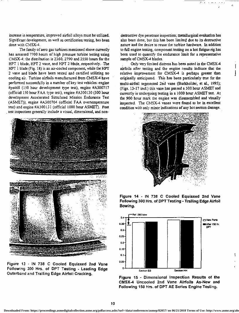
The family of aero gas turbines mentioned above currently has amassed 7700 hours of high pressure turbine testing using CMSX-4: the distribution is 2360, 2790 and 2550 hours for the HPT 1 blade, HPT 2 vane, and PITT 2 blade, respectively. The HPT 1 blade (Fig. 18) is an air-cooled component, while the HPT 2 vane and blade have been tested and certified utilizing no cooling air. Turbine airfoils manufactured from CMSX-4 have performed successfully in a number of key test vehicles: engine #ps468 (150 hour development type test), engine #A300717 (official 150 hour FAA type test), engine #A300130 (500 hour development Accelerated Simulated Mission Endurance Test (ASIvIET)), engine #A300704 (official FAA overtemperature test) and engine #A300131 (official 1000 hour ASMET). Post test inspections generally include a visual, dimensional, and non-
Figure 13 - IN 738 C Cooled Equiaxed 2nd Vane Following 300 Hrs. of DPT Testing - Leading Edge Outerband and Trailing Edge Airfoil Cracking.
destructive dye penetrant inspection, metallurgical evaluation has also been done, but this has been limited due to its destructive nature and the desire to reuse the turbine hardware. In addition to full engine testing, component testing on a hot fatigue rig has been used to quantify the endurance limit for a representative sample of CMSX-4 blades.
Only very limited distress has been noted in the CMSX-4 airfoils after testing and the engine results indicate that the relative improvement for CMSX-4 is perhaps greater than originally anticipated. This has been particularly true for the multi-airfoil segmented 2nd vane (Burkholder, et al., 1995); (Figs. 13-17 incl.) this vane has passed a 500 hour ASMET and currently is undergoing testing in a 1000 hour ASMET test. At the 900 hour mark the engine was disassembled and visually inspected. The CMSX-4 vanes were found to be in excellent condition with only minor indications of any hot section damage.
Figure 14 - IN 738 C Cooled Equiaxed 2nd Vane Following 300 Hrs. of DPT Testing - Trailing Edge Airfoil Bowing.
5 i 3
5
2
5
1
6
F.
Becton BB
Se000 MH
Figure 15 - Dimensional Inspection Results of the CMSX-4 Uncooled 2nd Vane Airfoils As-New and Following 150 Hrs. of DPT AE Series Engine Testing.
0.
0
0.
0.
rRef .060 bow
cy New Parts
IN Mr 150 hr. DPT
10
Downloaded From: https://proceedings.asmedigitalcollection.asme.org/pdfaccess.ashx?url=/data/conferences/asmep/82057/ on 06/21/2018 Terms of Use: http://www.asme.org/about-asme/terms-of-use
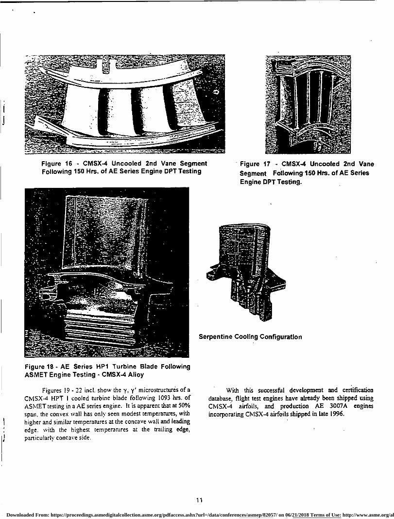
Serpentine Cooling Configuration
ss-4.Aia
—
, 0-2sSrtn.: -.sr ,"'"1•11-:'
Figure 16 - CMSX-4 Uncooled 2nd Vane Segment Following 150 Hrs. of AE Series Engine OPT Testing
• Figure 17 - CMSX-4 Uncooled 2nd Vane Segment Following 150 Hrs. of AE Series Engine OPT Testing.
Figure 18 - AE Series HP1 Turbine Blade Following ASMET Engine Testing - CMSX-4 Alloy
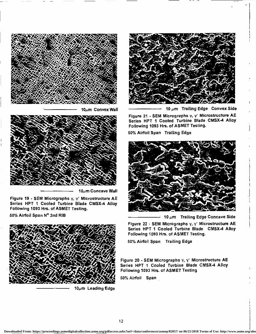
Figures 19 - 22 incl. show the y, y' microstructures of a
CNISX-4 HPT 1 cooled turbine blade following 1093 hrs. of
ASNIET testing in a AE series engine. It is apparent that at 50%
span, the convex wall has only seen modest temperatures, with
higher and similar temperatures at the concave wall and leading
edge. with the highest temperatures at the trailing edge,
particularly concave side.
• 1
With this successful development and certification database, flight test engines have already been shipped using CMSX-4 airfoils, and production AE 3007A engines incorporating CMSX-4 airfoils shipped in late 1996.
Downloaded From: https://proceedings.asmedigitalcollection.asme.org/pdfaccess.ashx?url=/data/conferences/asmep/82057/ on 06/21/2018 Terms of Use: http://www.asme.org/about-asme/terms-of-use
10mni Leading Edge
10grn Concave Wall
Figure 19 - SEM Micrographs y, y' Microstructure AE Series HPT 1 Cooled Turbine Blade CMSX-4 Alloy Following 1093 Hrs. of ASMET Testing.
50% Airfoil Span le 2nd RIB
10 ban Trailing Edge Convex Side
Figure 21 - SEM Micrographs y, y' Microstructure AE Series HPT 1 Cooled Turbine Blade CMSX-4 Alloy Following 1093 Hrs. of ASMET Testing.
50% Airfoil Span Trailing Edge
10 ALT Trailing Edge Concave Side
Figure 22 - SEM Micrographs y, y' Microstructure AE Series HPT 1 Cooled Turbine Blade CMSX-4 Alloy Following 1093 Hrs. of ASMET Testing.
50% Airfoil Span Trailing Edge
Figure 20 - SEM Micrographs y, y' Microstructure AE Series HPT 1 Cooled Turbine Blade CMSX-4 Alloy Following 1093 Hrs. of ASMET Testing
50% Airfoil Span
12
Downloaded From: https://proceedings.asmedigitalcollection.asme.org/pdfaccess.ashx?url=/data/conferences/asmep/82057/ on 06/21/2018 Terms of Use: http://www.asme.org/about-asme/terms-of-use
ROLLS-ROYCE MILITARY ENGINE EXPERIENCE
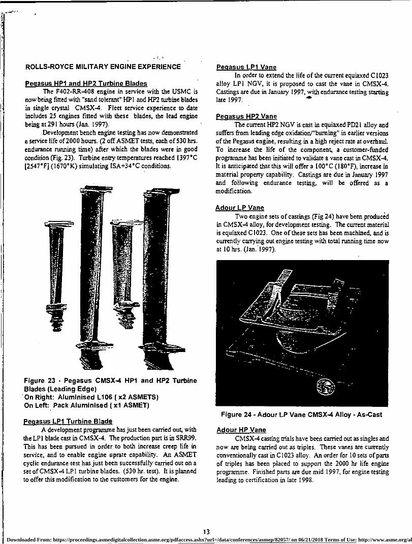
peoasus HP1 and I4P2 Turbine Blades The F402-RR-408 engine in service with the USMC is
now being fitted with "sand tolerant" HP! and HP2 turbine blades in single crystal CMSX-4. Fleet service experience to date includes 25 engines fitted with these blades, the lead engine
being at 291 hours (Jan. 1997). Development bench engine testing has now demonstrated
a service life of 2000 hours. (2 off ASMET tests, each of 530 hrs. endurance running time) after which the blades were in good
condition (Fig. 23). Turbine entry temperatures reached 1397°C
(2547 ° Fj (1670°K) simulating ISA+34°C conditions.
Figure 23 - Pegasus CMSX-4 HP1 and HP2 Turbine Blades (Leading Edge) On Right: Aluminised L106 ( x2 ASMETS) On Left: Pack Aluminised ( x1 ASMET)
pegasus LP1 Turbine Blade A development programme has just been carried out, with
the LP I blade cast in CMSX-4. The production part is in SRft99. This has been pursued in order to both increase creep life in
service, and to enable engine uprate capability. An ASMET cyclic endurance test has just been successfully carried out on a set of CMSX -4 LP I turbine blades. (530 hr. test). It is planned to offer this modification to the customers for the engine.
Pegasus LP1 Vane In order to extend the life of the current equiaxed C1023
alloy LP I NGV, it is proposed to cast the vane in CMSX-4. Castings are due in January 1997, with endurance testing starting late 1997.
Pegasus HP2 Vane The current HP2 NGV is cast in equiaxed PD21 alloy and
suffers from leading edge oxidation/burning" in earlier versions of the Pegasus engine, resulting in a high reject rate at overhaul.
To increase the life of the component, a customer-funded programme has been initiated to validate a vane cast in CMSX-4. It is anticipated that this will offer a 100°C (180°F), increase in
material property capability. Castings are due in January 1997 and following endurance testing, will be offered as a modification.
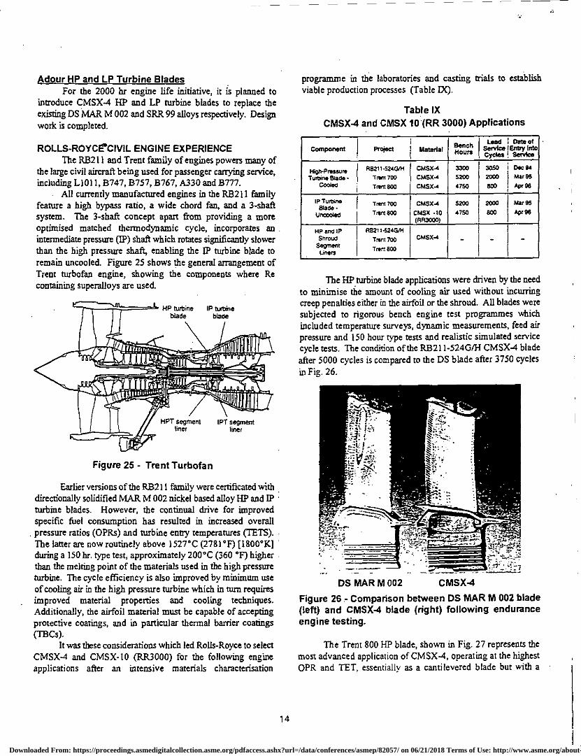
Adour LP Vane Two engine sets of castings (Fig 24) have been produced
in CMSX-4 alloy, for development testing. The current material is equiaxed C1023. One of these sets has been machined, and is currently carrying out engine testing with total naming time now at 10 hrs. (Jan. 1997).
Figure 24- Adour LP Vane CMSX-4 Alloy - As-Cast
Adour HP Vane CMSX-4 casting trials have been carried out as singles and
now are being carried out as triples. These vanes are currently conventionally cast in C1023 alloy. An order for 10 sets of parts of triples has been placed to support the 2000 hr life engine programme. Finished parts are due mid 1997, for engine testing leading to certification in late 1998.
13 Downloaded From: https://proceedings.asmedigitalcollection.asme.org/pdfaccess.ashx?url=/data/conferences/asmep/82057/ on 06/21/2018 Terms of Use: http://www.asme.org/about-asme/terms-of-use
HP turbine IP turbine blade blade
-taw 'iv Pt; Maliwil
asess HPT segment IPT segmen
liner liner
Adour HP and LP Turbine Blades For the 2000 hr engine life initiative, it is planned to
introduce CMSX-4 HP and LP turbine blades to replace the existing DS MAR M 002 and SRR 99 alloys respectively. Design work is completed.
ROLLS-ROYCE.CIVIL ENGINE EXPERIENCE The RB211 and Trent family of engines powers many of
the large civil aircraft being used for passenger carrying service, including L1011, 8747, B757, B767, A330 and 8777.
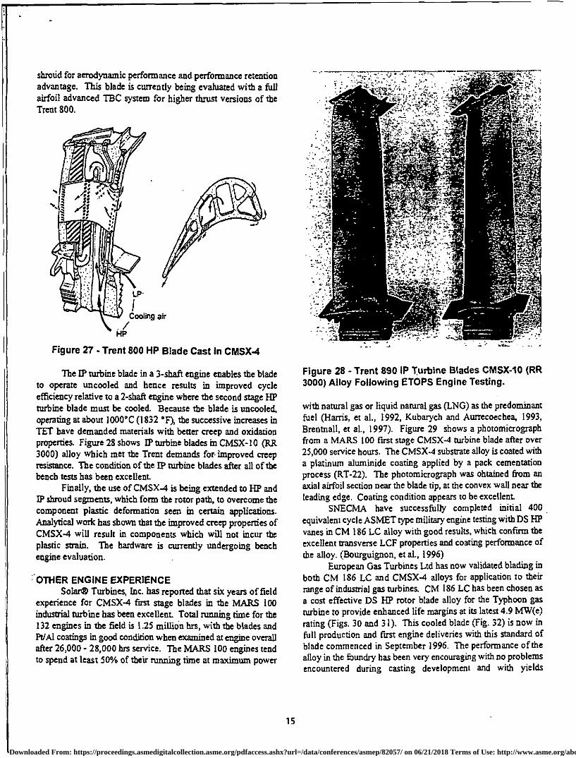
All currently manufactured engines in the R8211 family feature a high bypass ratio, a wide chord fan, and a 3-shaft system. The 3-shaft concept apart from providing a more optimised matched thermodynamic cycle, incorporates an intermediate pressure (TP) shaft which rotates significantly slower than the high pressure shaft, enabling the rp turbine blade to remain uncooled. Figure 25 shows the general arrangement of Trent turbofan engine, showing the components where Re containing superalloys are used.
Figure 25 - Trent Turbofan
Earlier versions of the RB211 family were certificated with directionally solidified MAR M 002 nickel based alloy HP and IP • turbine blades. However, the continual drive for improved specific fuel consumption has resulted in increased overall pressure ratios (OPFts) and turbine entry temperatures (TETS). The latter are now routinely above 1527°C (2781°F) [1800°K] during a 150 hr. type test, approximately 200°C (360 °F) higher than the melting point of the materials used in the high pressure turbine. The cycle efficiency is also improved by minimum use of cooling air in the high pressure turbine which in turn requires improved material properties and cooling techniques. Additionally, the airfoil material must be capable of accepting protective coatings, and in particular thermal barrier coatings (TB Cs).
It was these considerations which led Rolls-Royce to select CMSX-4 and CMSX- l0 (RR3000) for the following engine applications after an intensive materials characterisation
programme in the laboratories and casting trials to establish viable production processes (Table IX).
Table IX CMSX-4 and CMSX 10 (RR 3000) Applications
Component Material Bench Hours
Lead Serulce Cycles
Detect Entry Into Service
High-Pressure Turbine sta.-
Cooled
R821 1-5240/H Trim 700 "NMI 800
CMSX-4 CM5X-4 CM5X-4
3300 5200 4750
3050 2000 800
Dec 94 Mar 95 Apr 98
IP Turbine Slade -
(Incanted
Trent 700 Tram 800
C24SX-4
CMS% -10 (FIR3CCO)
5200
4750
2000
803
?Aar 95
Apr 96
HP and iP Shroud
Segment Liners
R9211-5243A1 Tram 700 Trent 800
C51524 - - -
The HP turbine blade applications were driven by the need to minimise the amount of cooling air used without incurring creep penalties either in the airfoil or the shroud. All blades were subjected to rigorous bench engine test programmes which included temperature surveys, dynamic measurements, feed air pressure and 150 hour type tests and realistic simulated service cycle tests. The condition of the RB211-5240/1-1 CMSX-4 blade after 5000 cycles is compared to the DS blade after 3750 cycles in Fig. 26.
DS MAR M 002 CMSX-4
Figure 26 - Comparison between DS MAR Ni 002 blade (left) and CMSX-4 blade (right) following endurance engine testing.
The Trent 800 HP blade, shown in Fig. 27 represents the most advanced application of CMSX-4, operating at the highest OPR and TET, essentially as a cantilevered blade but with a
14
Downloaded From: https://proceedings.asmedigitalcollection.asme.org/pdfaccess.ashx?url=/data/conferences/asmep/82057/ on 06/21/2018 Terms of Use: http://www.asme.org/about-asme/terms-of-use
shroud for aerodynamic performance and performance retention advantage. This blade is currently being evaluated with a nth airfoil advanced TBC system for higher thrust versions of the Trent 800.
Figure 27 - Trent 800 HP Blade Cast In CMSX-4
The 1P turbine blade in a 3-shaft engine enables the blade to operate =cooled and hence results in improved cycle efficiency relative to a 2-shaft engine where the second stage HP turbine blade must be cooled. Because the blade is uncooled, operating at about 1000°C (1832 °F), the successive increases in TET have demanded materials with better creep and oxidation properties. Figure 28 shows IP turbine blades in CMSX-10 (RR 3000) alloy which met the Trent demands for improved creep resistance. The condition of the 13) turbine blades after all of the bench tests has been excellent.
Finally, the use of CMSX-4 is being extended to HP and IP shroud segments, which form the rotor path, to overcome the component plastic deformation seen in certain applications. Analytical work has shown that the improved creep properties of CMSX-4 will result in components which will not incur the plastic strain. The hardware is currently undergoing bench engine evaluation.
: . OTHER ENGINE EXPERIENCE Solara Turbines, Inc. has reported that six years of field
experience for CMSX-4 first stage blades in the MARS 100 industrial turbine has been excellent Total running time for the 132 engines in the field is 1.25 million hrs, with the blades and Pal coatings in good condition when examined at engine overall after 26,000 - 28,000 Firs service. The MARS 100 engines tend to spend at least 50% of their miming time at maximum power
Figure 28 - Trent 890 IP Turbine Blades CMSX-10 (RR 3000) Alloy Following ETOPS Engine Testing.
with natural gas or liquid natural gas (LNG) as the predominant fuel (Harris, et al., 1992, Kubarych and Autrecoechea, 1993, Brentnall, et al., 1997). Figure 29 shows a photomicrograph from a MARS 100 first stage CM5X-4 turbine blade after over 25,000 service hours. The CMSX-4 substrate alloy is coated with a platinum aluminide coating applied by a pack cementation process (RT-22). The photomicrograph was obtained from an axial airfoil section near the blade tip, at the convex wall near the leading edge. Coating condition appears to be excellent
SNECMA have successfully completed initial 400 equivalent cycle ASMET type military engine testing with DS HP vanes in CM 186 LC alloy with good results, which confirm the excellent transverse LCF properties and coating performance of the alloy. (Bourguignon, et al., 1996)
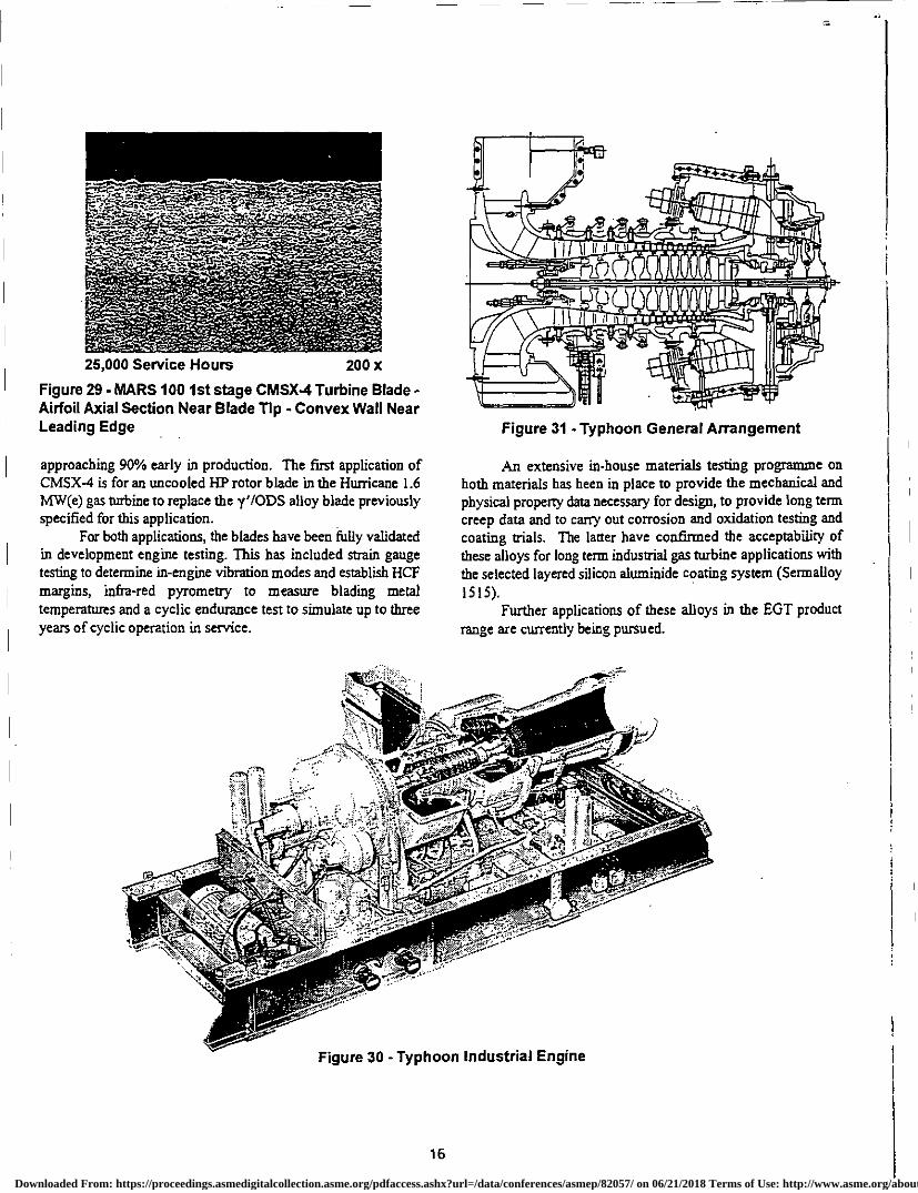
European Gas Turbines Ltd has now validated blading in both CM 186 LC and CMSX-4 alloys for application to their range of industrial gas turbines. CM 186 LC has been chosen as a cost effective DS HP rotor blade alloy for the Typhoon gas turbine to provide enhanced life margins at its latest 4.9 MW(e) rating (Figs. 30 and 31). This cooled blade (Fig. 32) is now in full production and first engine deliveries with this standard of blade commenced in September 1996. The performance of the alloy in the Eaundry has been very encouraging with no problems encountered during casting development and with yields
15
Downloaded From: https://proceedings.asmedigitalcollection.asme.org/pdfaccess.ashx?url=/data/conferences/asmep/82057/ on 06/21/2018 Terms of Use: http://www.asme.org/about-asme/terms-of-use
25,000 Service Hours 200 x
Figure 29 - MARS 100 1st stage CMSX-4 Turbine Blade - Airfoil Axial Section Near Blade Tip - Convex Wall Near Leading Edge
approaching 90% early in production. The first application of CMSX-4 is for an uncooled HP rotor blade in the Hurricane 1.6 MW(e) gas turbine to replace the y'/ODS alloy blade previously specified for this application.
For both applications, the blades have been fully validated in development engine testing. This has included strain gauge testing to determine in-engine vibration modes and establish HCF margins, infra-red pyrometry to measure blading metal temperatures and a cyclic endurance test to simulate up to three years of cyclic operation in service.
Figure 31 - Typhoon Genera Arrangement
An extensive in-house materials testing programme on both materials has been in place to provide the mechanical and physical property data necessary for design, to provide long term creep data and to carry out corrosion and oxidation testing and coating trials. The latter have confirmed the acceptability of these alloys for long term industrial gas turbine applications with the selected layered silicon aluminide coating system (Sermalloy 1515).
Further applications of these alloys in the EGT product range are currently being pursued.
Figure 30- Typhoon Industrial Engine
16
Downloaded From: https://proceedings.asmedigitalcollection.asme.org/pdfaccess.ashx?url=/data/conferences/asmep/82057/ on 06/21/2018 Terms of Use: http://www.asme.org/about-asme/terms-of-use
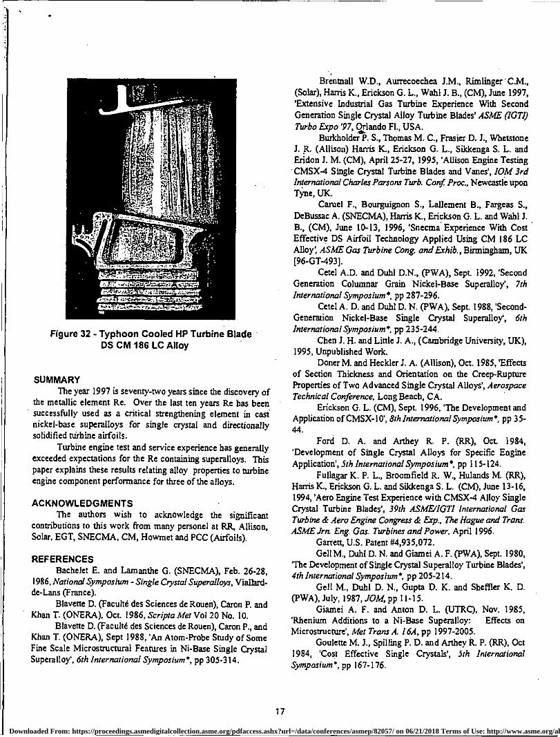
Figure 32 - Typhoon Cooled HP Turbine Blade DS CM 186 LC Alloy
SUMMARY The year 1997 is seventy-two years since the discovery of
the metallic element Re. Over the last ten years Re has been successfully used as a critical strengthening element in cast nickel-base superalloys for single crystal and directionally solidified Mrbine airfoils.
Turbine engine test and service experience has generally exceeded expectations for the Re containing superalloys. This paper explains these results relating alloy properties to turbine engine component performance for three of the alloys.
ACKNOWLEDGMENTS The authors wish to acknowledge the significant
contributions to this work from many personel at RR, Allison, Solar, EGT, SNECMA, CM, Howmet and PCC (Airfoils).
REFERENCES Bachelet E. and Lamanthe G. (SNECMA), Feb. 26-28,
1986, National Symposium - Single Crystal Superalloys, Viallard-de-Lans (France).
Blavette D. (Facult6 des Sciences de Rouen), Caron P. and Khan T. (ONERA), Oct. 1986, Scripta Met Vol 20 No. 10.
Blavette D. (Faculte des Sciences de Rouen), Caron P., and Khan T. (ONERA), Sept 1988, 'An Atom-Probe Study of Some Fine Scale Microstructural Features in Ni-Base Single Crystal Superalloy', 6th International Symposium*, pp 305-314.
Brentnall W.D., Aurrecoechea J.M., Rimlinger • C.M., (Solar), Harris K., Erickson G. L., Wahl J. B., (CM), June 1997, 'Extensive Industrial Gas Turbine Experience With Second Generation Single Crystal Alloy Turbine Blades' ASME (IGTI) Turbo Expo '97, Orlando Fl., USA.
Burkholder P. S., Thomas M. C., Frasier D. J., Whetstone J. R. (Allison) Harris K., Erickson G. L., Silckenga S. L. and Eridon J. M. (CM), April 25-27, 1995, 'Allison Engine Testing CMSX-4 Single Crystal Turbine Blades and Vanes', 10M 3rd International Charles Parsons Turb. Cant Proc., Newcastle upon Tyn. e, UK
Camel F., Bourguignon S., Lallement B., Fargeas S., DeBussac A. (SNECMA), Harris K., Erickson G. L. and Wahl J. B., (CM), June 10-13, 1996, 'Snecma Experience With Cost Effective DS Airfoil Technology Applied Using CM 186 LC Alloy', ASME Gas Turbine Cong. and Exhib., Birmingham, UK [96-GT-493].
Cetel A.D. and Duhl D.N., (PWA), Sept 1992, 'Second Generation Columnar Grain Nickel-Base Superalloys, 7th International Symposium , pp 287-296.
Cetel A. D. and Duhl D. N. (PWA), Sept 1988, 'Second-Generation Nickel-Base Single Crystal Superalloy, 6th International Symposium*, pp 235-244.
Chen J. H. and Little J. A., (Cambridge University, UK), 1995, Unpublished Work.
Doner M. and Heckler J. A. (Allison), Oct. 1985, 'Effects of Section Thickness and Orientation on the Creep-Rupture Properties of Two Advanced Single Crystal Alloys', Aerospace Technical Conference, Long Beach, CA.
Erickson G. L. (CM), Sept. 1996, 'The Development and Application of CMSX-10', 8th International Symposium', pp 35- 44.
Ford D. A. and Arthey R. P. (RR), Oct 1984, 'Development of Single Crystal Alloys for Specific Engine Application', 5th International Symposium*, pp 115-124.
Fullagar K. P. L., Broomfield R. W., Hulancis M. (RR), Harris K., Erickson G. L. and Sikkenga S. L. (CM), June 13-16, 1994, 'Aero Engine Test Experience with CMSX-4 Alloy Single Crystal Turbine Blades', 39th ASMEIIGTI International Gas Turbine & Aero Engine Congress & Exp., The Hague and Trans. ASME Jrn. Eng. Gas. Turbines and Power, April 1996.
Garrett, U.S. Patent #4,935,072. Gell M., Duhl D. N. and Giamei A. F. (PWA), Sept. 1980,
'The Development of Single Crystal Superalloy Turbine Blades', 4th International Symposium', pp 205-214.
Gell M., Duhl D. N., Gupta D. K. and Sheffler K. D. (PWA), July, 1987, JOM, pp 11-15.
Giamei A. F. and Anton D. L. (UTRC), Nov. 1985, 'Rhenium Additions to a Ni-Base Superalloy: Effects on Microstructure', Met Trans A. 16A, pp 1997-2005.
Goulette M. J., Spilling P. D. and Arthey R. P. (RR), Oct 1984, 'Cost Effective Single Crystals', 5th International Symposium*, pp 167-176.
17
Downloaded From: https://proceedings.asmedigitalcollection.asme.org/pdfaccess.ashx?url=/data/conferences/asmep/82057/ on 06/21/2018 Terms of Use: http://www.asme.org/about-asme/terms-of-use
Harris K., Erickson G. L. and Schwer R. E. (CM), 1983, Development of the Single Crystal Alloys CMSX-2 and CMSX-3 For Advanced Technology Turbines', ASME Paper 483-6T-244.
Harris K., Erickson G. L. and Schwer It E. (CM), Oct. 1984, 'MAR M 247 Derivations - CM 247 LC® DS Alloy, CMSX41) Single Crystal Alloys, Properties and Performance', 5th Inteitational Symposium*, pp 221-230.
Harris K, Erickson G. L. and Schwer R. E. (CM), Oct. 6- 9, 1986, 'CMSX Single Crystal, CM DS and Integral Wheel Alloys Properties and Performance', Cost 50/501 Conf. Liege Proc., pp 709-728.
Harris K., Erickson G. L. and Schwer R. E. (CM), Frasier D. J. and Whetstone J. It (Allison), Sept 24-27, 1990, 'Process and Alloy Optimization for CMSX-4 Superalloy Single Crystal • Airfoil', Cost Conference Liege, Proc. Pan II, pp 1281-1300.
Harris K, Erickson G. L., Silckenga S. L. (CM), Brentnall W. D., Aurrecoechea J. M. and Kubarych K. G. (Solar0), Sept 1992, 'Development of the Rhenium Containing Superalloys CMSX-4 and CM 186 LC For Single Crystal Blade and Directionally Solidified Vane Applications in Advanced Turbine Engines', 7th International Symposium*, pp 297-306.
Holmes J. W. et al. (MIT), O'Hara K S. [GE (AE)J, 1988, Thermal Fatigue Testing of Coated Monocrystalline Superalloys', ASTM STP 942, Phil, pp 672-691.
Khan T. (ONERA) and Brun M. (Turbomeca), June 1989, Symposium on Single Crystal Alloys, MTU/SMCT, Munich.
Korinko P. S., Barber M. J. and Thomas M. C., (Allison), June 10-13, 1996, 'Coating Characterization and Evaluation of DS CM 186 LC and SX CMSX-4', ASME Gas Turbine Cons and Erhib, Birmingham, UK.
Kubarych K. G. and Aurrecoechea J. M. (Solar) 'Post Field Test Evaluation of an Advanced Industrial Gas Turbine First Stage Turbine Blade', Oct. 17-21 1993, TMS/ASM Mat Wk '93 Proc., PA
Meyer - Olbersleben F., Rezai-Aria F. (Swiss Fed Institute of Tech) and Goldschrnidt D (MTU), Sept 1992, 'Investigation of the Thermal Fatigue Behavior of Single Crystal Nickel-Based Superalloys SRR 99 and CMSX-4', 7th International Symposium* pp 785-794.
Meyer - Olbersleben, F. Engler-Pinto Jr., C. C. and Rizai-Aria F., 1996, 'On Thermal Fatigue of Nickel-Based Superalloys', Thermomechanical Fatigue Behavior of Materials: Second Volume. ASTM 577 3 1263 Michael J. Verrilli and Michael G. Castelli, (1996) &is , American Socieorfor Testing and Materials.
Miglietti W.M. and Pennefather R. C. (CSIR), 19961 ASME Gas Turbine Cong and Exhib, Bilmingham, UK.
Pessah M., Caron P. and Khan T. (ONERA), Sept 1992, 'Effect of p Phase on The Mechanical Properties of a Nickel-Base Single Crystal Superalloy', 7th International Symposium, pp 567-576.
Petrov D. A. and Tumanov A.T., 1973, The Use of Single Crystal Blades, Aircraft Engineering No. 9.
Pollack T. M. and Argon A. S. (MIT), 1992, Aeta Metallurgica at Materialia, 40, pp 1.
PW 2037 Engine Display, Sept 1994, Farnborough Air Show (PWA),
Roan F. (Westinghouse Electric Corp.), 1996 - Private Communication.
Ross E. W. and O'Hara K. S. (GE), Sept. 1996, 'Rene N4: A First Generation Single Crystal Turbine Airfoil Alloy With Improved Oxidation Resistance, Low Angle Boundary Strength and Superior Long Time Rupture Strength', 8th International Symposium*, pp 19-25.
Ross E. W. and O'Hara K. S. (GE), Sept 1992 b, 'Rene 142: A High Strength, Oxidation Resistant DS Turbine Airfoil Alloy', 7th International Symposium'', pp 257-265.
Strangman T. E., et al. (Garrett), Sept 1980, 'Development of Exothermically Cast Single Crystal MAR M 247 and Derivative Alloys', 4th International Symposium*, pp 215-224.
Thomas M. C., Helmink R. C., Frasier D. J., Whetstone J. R. (Allison), Harris K., Erickson G. L., Sildcenga S. L. and Eridon J. M. (CM), (Oct. 3-6, 1994) 'Allison Manufacturing, Property and Turbine Engine Performance of CMSX-4 Single Crystal
• Airfoils', Cost 501 Conf Proc, Liege. Walston W. S., O'Hara K. S., Ross E. W., Pollock T.M.
and Murphy W. H.. (GE), Sept. 1996, 'Rene N6: Third Generation Single Crystal Superalloy', 8th International Symposium, pp 27-34.
Wortrnann J., Wege R. (MTU), Harris IC, Erickson G. L. and Schwer It E. (CM), June 29, 1988, 'Low Density Single Crystal Superalloy CMSX-60, 7th World Conference on Investment Casting Proc., Munich. • Wukusick C. S. and Buchakjian L. Jr. [GE (AE)1], March 13, 1991, 'Improved Property - Balanced Nickel-Base Superalloys for Producing Single Crystal Articles' UK Patent Application tlGB 2 235 697A.
Wulcusick C. S., [GE (AE)), Aug. 25, 1980, Fnl. Rep. 'Directional Solidification Alloy Development', NAVAIR Contr. N62269-78-C-0315.
Yamazaki M., et al. (NR1M), Oct 1984, 'Alloy Design for High Strength Nickel-Base Single Crystal Alloys', 5th International Symposium*, pp 157-166.
Yukawa N., et al. (Toyohashi Univ.), Sept 1988, 'High Performance Single Crystal Superalloys Developed By The d-Electrons Concept', 6th International Symposium*, pp 225-234.
• Superalloys, Seven Springs, PA., TMS Proc.
18
Downloaded From: https://proceedings.asmedigitalcollection.asme.org/pdfaccess.ashx?url=/data/conferences/asmep/82057/ on 06/21/2018 Terms of Use: http://www.asme.org/about-asme/terms-of-use