development and validation of an extended two...
TRANSCRIPT

Proceedings of ICAPP 2007 Nice, France, May 13-18, 2007
Paper 7483
DEVELOPMENT AND VALIDATION OF AN EXTENDED TWO-PHASE COMPUTATIONAL FLUID DYNAMICS MODEL FOR THE ANALYSIS OF
BOILING FLOW IN REACTOR FUEL ASSEMBLIES
Adrian Tentner, W. David Pointer, Tanju Sofu, David Weber Argonne National Laboratory, 9700 S. Cass Avenue, Argonne, Illinois, USA
Simon Lo and Andrew Splawski CD-adapco Ltd., 200 Shepherds Bush Road, London W6 7NL, UK
Abstract – This paper presents recent advances in the development and integral validation of a two-phase Computational Fluid Dynamics (CFD) computer model (CFD-BWR) that allows the detailed analysis of the two-phase flow and heat transfer phenomena in Boiling Water Reactor (BWR) fuel bundles. The CFD-BWR code is being developed as a customized module built on the foundation of the commercial CFD-code STAR-CD which provides general two-phase flow modeling capabilities.
I. INTRODUCTION A new code, CFD-BWR [1, 2] is being developed for
the fine-mesh, 3-dimensional simulation of the two-phase flow phenomena that occur in a Boiling Ware Reactor (BWR) fuel assembly. These phenomena include coolant phase changes and multiple flow topologies that directly influence the reactor performance. The CFD-BWR code is being developed as a specialized module built on the foundation of the commercial CFD code STAR-CD [3] which provides general two-phase flow modeling capabilities. A first generation of models describing the inter-phase mass, momentum, and energy transfer phenomena specific for bubbly flow topologies have been previously implemented in the CFD-BWR module and described in [1, 2]. This paper describes the second generation of boiling models which allows STAR-CD and CFD-BWR to simulate a wide spectrum of local flow topologies expected in a BWR fuel assembly and is referred to as the Extended Boiling Framework (EBF). The EBF has been developed as part of an effort sponsored by US DOE and EPRI to develop an integrated Neutronic and Thermal-Hydraulic Code System for BWR Applications [4]. The integral validation of the new EBF models is focused on analyses of the NUPEC BWR Full-size Bundle Tests (BFTBT), performed in the framework of the BFBT Benchmark Exercise sponsored by NUPEC, OECD NEA, and US NRC [5]. Initial results of BFBT void distribution
experiment analyses performed with the Extended Boiling Framework models are presented and discussed.
II. TWO-PHASE FLOW MODEL DEVELOPMENT
I. Approach
The CFD-BWR code is being developed as a
customized module built on the foundation of the commercial CFD-code STAR-CD which provides general two-phase flow modeling capabilities. We have described in [1] the model development strategy that has been adopted by the development team for the simulation of boiling flow phenomena in a BWR fuel bundle. A central concept is that of a local inter-phase surface topology map which determines the local flow configuration as a function of flow conditions and prescribes which models and properties are relevant for each computational cell. The sub-cooled bubbly topology, with vapor bubbles flowing in a continuous liquid, has been implemented in the first generation boiling model and already has an established base of CFD modeling experience. The Extended Boiling Framework uses an inter-phase surface topology map that includes, in addition to the bubbly topology, a droplet or mist topology and a transition topology. The droplet topology consists of liquid droplets flowing in a continuous vapor stream.

Proceedings of ICAPP 2007 Nice, France, May 13-18, 2007
Paper 7483
The direct simulation of the transition from bubbly flow, through slug and churn flow, to annular flow is not currently within our scope for practical reasons. To resolve large bubbles of size comparable to channel diameter would consume large computer resources on the necessarily fine grids and short timescales, and above all on the extraction of suitable time-averaged results from the simulation of a chaotic process. Instead, for transition-topology cells we use a topology-based combination of the terms appropriate for the basic topologies, bubbly and mist. This can be interpreted as having a transition topology cell where a fraction of the cell volume presents the bubbly topology while the remaining volume presents the mist topology. An alternative interpretation is that the map is prescribing the probability of being in one topology or the other while solving equations for the time-averaged flow.
II. Transport Equations
The STAR-CD Eulerian two-phase solver tracks the mass, momentum, and energy of the liquid and vapor phases in each computational cell. Full details of the Eulerian two-phase flow models in STAR-CD can be found in [3] and [6]. The main equations solved are the conservation of mass, momentum and energy for each phase.
The conservation of mass equation for phase k is:
( ) ( ) ikkikkkkk mmu.t
&& −=∇+∂∂ ραρα (1)
The conservation of momentum equation for phase k is:
( ) ( ) ( )( )Mgp
.uu.ut
kkk
tkkkkkkkkkk
++∇−
=+∇−∇+∂∂
ραα
τταραρα (2)
The conservation of energy equation for phase k is:
( ) ( ) ( ) QT.eu.et kkkkkkkkkk =∇∇−∇+∂∂ λαραρα (3)
An extended k - ε model containing extra source terms that arise from the inter-phase forces present in the momentum equations is used to model turbulence in the flow.
III. Inter-phase Surface Topology Map and Local Flow
Configuration
Inter-phase interactions in multiphase fluids depend on both the area and the topology of interface. Sub-channel thermal-hydraulic codes rely on flow regime maps to evaluate the interface topology using cross-section-averaged flow parameters. CFD codes, which divide the flow space into much finer computational cells cannot rely
on the traditional sub-channel flow regimes, but must evaluate instead the local inter-phase surface topology. The ensemble of many computational cells with relatively simple inter-phase surface topologies can provide complex global topologies that include all the traditional sub-channel flow regimes.
Most of the advanced CFD codes currently allow the simulation of dispersed flows only (bubbly or mist flows) where the topology is originally defined. The first generation of the STAR-CD CFD-BWR boiling model used a bubbly flow topology in all computational cells. The second generation of the boiling model uses a locally calculated topology variable to allow the following topologies: a) a bubbly flow topology with spherical vapor bubbles in a continuous liquid, b) a droplet or mist topology with spherical liquid droplets flowing in a continuous vapor field, and c) a transition topology which combines the features of the two previous topologies in various proportions. The local topology is determined in this model using a local topology map based on the local void fraction. This 1-dimensional topology map is illustrated in Fig. 1 together with the associated flow topologies.
This topology map does not address directly the
presence of cells that contain a sharp single-connected interface, such as wall cells that contain a thin liquid film. However, wall cells that satisfy specific conditions are treated in the 2nd generation boiling model as a special liquid film topology case. Inter-phase mass, momentum, and energy transfer models have been developed for the 2nd generation two-phase flow topologies illustrated in Fig. 1 and calculations for the verification and validation of these models are now underway. The use of the local inter-phase surface topology map allows the modeling of complex sub-channel scale topologies that contain many computational cells with one of the topologies shown in Fig. 1. E.g., the typical sub-channel annular flow regime
Fig. 1. Inter-Phase Surface Topology Map used for the 2nd Generation Boiling Model.

Proceedings of ICAPP 2007 Nice, France, May 13-18, 2007
Paper 7483
could be resolved into a distinct core flow region in which the gas phase is continuous and the local mist topology is used, separated by transition topology cells from a liquid film on the wall where the local bubbly topology is used.
A more complex inter-phase surface topology map, which allows the presence of cells containing a sharp single-connected liquid-vapor interface anywhere in the coolant channel in addition to the topologies presented in Fig. 1 is currently under development in an international collaborative effort to develop the third generation boiling model. This effort includes a more complex inter-phase surface topology map, which allows the presence of cells containing a sharp single-connected liquid-vapor interface anywhere in the coolant channel in addition to the topologies presented in Fig. 1. According to the 3rd generation 2-dimensional map, which has been described in Ref. [2], the inter-phase surface topology in each mesh cell is determined by two quantities, i.e. void fraction gα
and void fraction difference gαδγ ∇⋅= , at distances of
about the characteristic mesh size { }zyx ∆∆∆= ,,minδ . The 3rd generation boiling model will be used for BWR analyses when the model development and validation are completed.
IV. The extended boiling heat and mass transfer models
The inter-phase heat and mass transfer models were obtained by considering the heat transfer from the vapor and the liquid to the gas/liquid interface, as illustrated in Fig. 2a for a bubbly flow topology. The net heat transfer to the interface is used to compute the mass transfer rate between the two phases.
The heat transfer rate from the liquid to the interface is:
( )satliBlBlB TTAhq −=& (4) The heat transfer rate from the vapor to the interface
is: ( )satgiBgBgB TTAhq −=& (5)
Fig. 2a. Heat and mass transfer between a vapor bubble
and liquid
Similar heat transfer rate equations apply the droplet flow topology, shown in Fig. 2b, but both the liquid-side and vapor-side heat transfer coefficients are now calculated using different heat transfer correlations.
The heat transfer rate from the liquid to the interface is:
( )satliDlDlD TTAhq −=& (6) The heat transfer rate from the gas to the interface is:
( )satgiDgDgD TTAhq −=& (7)
Fig. 2b. Heat and mass transfer between a liquid
droplet and vapor In (4) through (7) the subscript B has been used to
denote the bubbly flow topology and the subscript D for the droplet flow topology. For the transition topology illustrated in Fig. 1 it is assumed that the inter-phase surface topology is a combination of the bubbly and droplet flow topologies determined by the topology variable θ1:
iDiBi AAA 11)1( θθ +−= (8) The heat transfer rates are then calculated from the
generalized equations:
( )( )( )satliDlDiBlBl TTAhAhq −+−= 111 θθ& (9)
( )( )( )satliDgDiBgBg TTAhAhq −+−= 111 θθ& (10)
Assuming that all the heat transferred to the
interface is used in mass transfer (i.e. evaporation or condensation), the inter-phase mass transfer rate can be written as:
fg
gl
hqq
m&&
&+
= (11)

Proceedings of ICAPP 2007 Nice, France, May 13-18, 2007
Paper 7483
V. The Wall Heat Transfer Model A model describing the heat transfer between the
heated wall and the coolant has also been developed. The heat flux from the wall to the liquid is divided into three parts according to a wall heat partitioning model which includes convective heat for the liquid, evaporative heat for generation of steam and quench heat for heating of liquid in the nucleation sites. The Extended Boiling Framework includes also models for the heat flux transferred to the vapor phase, allowing the modeling of dry-out situations. More details of the boiling heat and mass transfer model and the wall heat partitioning model can be found in Refs. [1], [2], and [6].
In coupling the flow analysis with neutronics, the temperatures of the fuel pin and cladding must be determined together with the coolant temperatures as a conjugate heat transfer problem. Heat transfer within the solids can be described by the following energy equation:
( )e
jji
j
sxT
xte
+⎟⎟⎠
⎞⎜⎜⎝
⎛
∂∂
∂∂
=∂
∂ λρ (12)
where es is the fission heat source. Equation (12) is solved together with the coolant energy equation (3) to obtain the temperature at the solid/fluid interface. When this wall temperature is greater than the saturation temperature, the boiling model described above is applied on the fluid side to produce vapor. Condensation on walls with temperature below the saturation temperature is also considered.
VI. The extended boiling momentum transfer models The inter-phase forces considered in the model are:
drag, turbulent drag, virtual mass, lift, and wall lubrication forces. In addition, inter-phase momentum transfer is associated with mass transfer, hence:
kikikiWLLMTD umumFFFFFM && −+++++= (13)
The second generation boiling model has extended the treatment of the inter-phase forces to cover the spectrum of flow topologies expected in a BWR fuel assembly. The drag force model, for example, covers bubbles in the sub-cooled or saturated bubbly flow topology, a mixture of Taylor bubbles and smaller bubbles in the slug-flow transition topology, and droplets in the droplet or mist topology. Details of the treatment of inter-phase forces can be found in [3] and [6].
III. TWO-PHASE FLOW MODEL VALIDATION
A comprehensive EBF validation strategy has been
developed which includes both validation analyses focused
on individual phenomenological models and integral test analyses including a combination of two-phase phenomena characteristic for BWR fuel assemblies. This validation strategy has been outlined in Ref. [7], together with results of experiment analyses focused on individual two-phase flow phenomena. The integral validation program, in which the applicability of the model to full BWR assemblies with realistic axial and radial pin power distributions is evaluated, is also in progress. A central component of the integral model validation is the analysis of the BFBT Benchmark Experiment [5] described below.
I. BFBT Benchmark Experiment Description
The simulations discussed in the following sections
consider an experimental test geometry consisting of sixty electrically heated pins organized in an eight by eight array. The electrically heated pins use the same cladding materials and match the outer diameter dimensions of BWR fuel pins. A large circular water channel, represented in the experiment by a sealed cylindrical cavity which contains no coolant, displaces the 4 array elements at the center of the assembly. Seven ferrule spacer grids with perimeter vanes are included in the assembly test section to both restrict the motion and deformation of the pins and introduce turbulence mixing into the flow field, as illustrated in Fig. 3. The external boundary of the test geometry is representative of a standard square BWR assembly can and its external surface is assumed to be well insulated.
Fig. 3. Illustration of the arrangement of heated pins, water channel and spacer grids in the BFBT test section.
A wide variety of instrumentation was included in the
BFBT experiments to provide data for the assessment of spacer grid performance directly from the experiments
Proceedings of ICAPP 2007 Nice, France, May 13-18, 2007
Paper 7483
themselves as well as for code validation. The total test section pressure drop was recorded, as well as intermediate pressure drops across each spacer grid. Absolute exit pressure, inlet temperature, outlet temperature, and inlet flow rate data are also recorded throughout the experiment. X-Ray densitometer measurements are made at three axial levels to obtain area averaged void fractions at those positions. Finally, a highly detailed two-dimensional void distribution map is measured 5 cm above the top of the heated section using CT scan technology.
All cases identified for the CFD benchmark exercise use a flat axial power profile, the same specified radial power profile, and have a fixed inlet subcooling of approximately 10 °C and an outlet pressure of 7.2 MPa. The flow rate through the assembly is approximately 15 kg/s, which results in a coolant velocity of approximately 2 m/s at the inlet of the pin bundle. Three different experiments with exit qualities of 5%, 12%, and 25% were analyzed as part of the BFBT benchmark exercise, although results for only the 5% and 25% cases are presented herein. The different exit qualities were achieved in the experiments by controlling the total current supplied to the test section.
II. Analysis of BFBT Void Distribution Experiments Two computational meshes were used in these studies
to describe the BFBT test geometry. First a block structured mesh was developed, incorporating the dimensions of the fuel pins, water channel and a simplified model of the spacer grids. Based on the experience gained using this model, a more refined model was developed using a combination of trimmed polyhedral cells and prismatic extrusion cells to describe the test section geometry. In the trimmed cell grid, the spacer grids are neglected in these initial calculations.
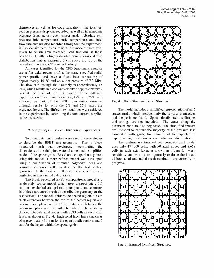
The block structured BFBT computational model is a moderately coarse model which uses approximately 3.5 million hexahedral and prismatic computational elements in a block structured mesh to describe the geometry of the test section. The model includes the heated region, a 5 cm thick extension between the top of the heated region and measurement plane, and a 15 cm extension between the measuring plane and the outlet boundary. The model is divided into 392 axial nodes, with 7680 cells in each axial layer, as shown in Fig. 4. Each axial layer has a thickness of approximately 10 mm for the open bundle regions and 5 mm for the layers within the spacer grids.
Fig. 4. Block Structured Mesh Structure.
The model includes a simplified representation of all 7 spacer grids, which includes only the ferrules themselves and the perimeter band. Spacer details such as dimples and springs are not included. The vanes along the perimeter band are also neglected. The simplified spacers are intended to capture the majority of the pressure loss associated with grids, but should not be expected to capture all significant impacts on radial void distribution.
The preliminary trimmed cell computational model uses only 477,000 cells, with 50 axial nodes and 8,668 cells in each axial layer, as shown in Figure 5. Mesh sensitivity studies to more rigorously evaluate the impact of both axial and radial mesh resolution are currently in progress.
Fig. 5. Trimmed Cell Mesh Structure.

Proceedings of ICAPP 2007 Nice, France, May 13-18, 2007
Paper 7483
The flow enters the computational domain through a constant temperature, constant velocity inlet boundary and exits the assembly through a constant pressure outlet boundary. A zero gradient condition is assumed for all other parameters at the outlet. Adiabatic no-slip wall conditions are specified at the inner surface of the assembly can and at the outer surface of the water channel. No-slip, constant heat flux wall boundaries are specified at the surface of each pin. User subroutines provide the heat flux based on the specified pin power distribution.
All simulations presented herein use the steady state version of the SIMPLE solver. In the present version of the Eulerian two-phase boiling model first order upwind differencing is the only differencing scheme available. A uniform bubble and droplet diameter of 1 mm was assumed in these calculations throughout the assembly for the bubbly and droplet flow topologies, respectively.
III. Discussion of Results
Preliminary simulations of the BFBT experiments
have been completed in two phases. Initially, simulations were performed using the first generation boiling model including only the bubbly flow topology, in order to test the modeling strategy and develop a suitable methodology for evaluating the convergence of the model. In these cases, the drag, turbulent drag and inertial forces were considered but the lift and wall lubrication forces were not included because the appropriate models were not yet available. In subsequent simulations, the second generation Extended Boiling Framework is activated to allow consideration of more complex flow topologies. Since the EBF is still under development only the drag and lift forces have been implemented for all topologies and were considered in these calculations.
Simulations using the BFBT model were completed using 40 2.3 GHz Xeon processors on Argonne National Laboratory’s (ANL) 360 processor jazz Linux cluster. The convergence criteria are defined such that all monitored residual values must fall below 10-3 and the maximum percent change in the area-averaged void fraction between the current and previous iteration must fall below 10-5. These criteria are satisfied after approximately 5000 steady state iterations.
III.1 Bubbly Flow Simulations with Block Structured Mesh
The two selected BFBT test cases with 5% and 25%
exit quality were simulated first using the block-structured computational mesh and the first generation bubbly flow topology model. The calculated axial distribution of void on an assembly area-averaged basis for the 5% exit quality
case is shown in Fig. 6. The calculated radial distribution at the exit plane for this case is shown in Fig. 7. Similarly the calculated axial assembly-averaged and radial exit void distributions are shown for the 25% quality case in Figs. 8 and 9. In both cases, the predicted exit assembly-averaged void fractions are consistent with expectations assuming homogeneous thermal equilibrium. However, the radial void distribution at the exit does not exhibit the expected tendency of boiling flows with high average void fractions (approximately 50% and 80% for the 5% quality and 25% quality cases, respectively) to develop substantial regions of vapor flow at the center of each sub-channel with liquid films forming on the wall. This trend has actually been observed in the BFBT measured detailed void distributions, although the actual data has not yet been released for detailed comparisons at this time. Indeed the opposite tendency is observed in the calculated results, particularly for the 25% quality case (Fig. 9), with void concentrated near the heated pin walls.
0.000.050.100.150.200.250.300.350.400.450.50
0 0.2 0.4 0.6 0.8 1
Normalized Axial Position
Void
Fra
ctio
n
Fig. 6. Axial Distribution of Assembly Area-Averaged Void Fraction for the BFBT Test Case with 5% exit quality, calculated using the First Generation Eulerian Two-Phase Model and the Block Structured Computational Mesh.
Fig. 7. Detailed two-dimensional Void Distribution at the measurement plane for the BFBT test case with 5% exit quality, calculated using the First Generation Eulerian Two-Phase Model and the Block Structured Computational Mesh.

Proceedings of ICAPP 2007 Nice, France, May 13-18, 2007
Paper 7483
0.000.100.200.300.400.500.600.700.800.90
0 0.2 0.4 0.6 0.8 1
Normalized Axial Position
Void
Fra
ctio
n
Fig. 8. Axial Distribution of Assembly Area-Averaged Void Fraction for the BFBT Test Case with 25% exit quality, calculated using the First Generation Eulerian Two-Phase Model and the Block Structured Computational Mesh.
Fig. 9. Detailed two-dimensional Void Distribution at the measurement plane for the BFBT Test Case with 25% exit quality, calculated using the First Generation Eulerian Two-Phase Model and the Block Structured Computational Mesh.
Fig. 10. Percent Error in the Channel Averaged Void Fraction at the Measurement Plane for the BFBT Test Case with 5% exit quality, calculated using the First Generation Eulerian Two-Phase Model and the Block Structured Computational Mesh
Fig. 11. Percent Error in the Channel Averaged Void Fraction at the Measurement Plane for the BFBT Test Case with 25% exit quality, calculated using the First Generation Eulerian Two-Phase Model and the Block Structured Computational Mesh.
This discrepancy between the calculated and the measured radial void distributions is attributed largely to the lack of the lift force model in these calculations, and it is shown to disappear when the appropriate lift force model is included, as illustrated in the next section
The relative error in the prediction of the channel averaged void fractions is presented for both cases in Figures 10 and 11. The channel averaged void fraction is accurately calculated in much of the assembly, with the exception of the regions near the unheated can wall and water channel surfaces, where the unrepresented inter-phase forces and flow topologies are expected to play a larger role.
III.2 Extended Boiling Framework Simulations with Block Structured Mesh
Initial simulations implementing the second generation
extended boiling framework were completed using the same block structured mesh as the first generation studies. The predicted axial distributions of assembly area-averaged void are not significantly changed as a consequence of the implementation of the additional flow topologies, however significant differences are observed in the radial void distribution at the measurement plane, as shown in Figs. 12 and 13 for the 5% and 25% exit quality cases, respectively.
As a consequence of the additional flow topologies and the implementation of the improved lift force model, regions of segregated liquid and vapor are clearly being predicted by the simulations for both the 5% and 25% exit quality cases. Although the vapor tends to migrate toward the center of the sub-channels and the presence of liquid films is predicted near some of the pins, some irregular liquid or low-void regions can be observed away from the pin walls.

Proceedings of ICAPP 2007 Nice, France, May 13-18, 2007
Paper 7483
Fig. 12. Detailed Radial Void Distribution at the Measurement Plane for the BFBT Test Case with 5% exit quality, calculated using the Second Generation Eulerian Two-Phase Model and the Block Structured Computational Mesh.
These results may be caused by the computational mesh structure used in these cases which is not optimal for the prediction of annular film and central mist region formation. It is also expected that the absence of turbulent drag and inertial forces, which have not yet been fully implemented in the EBF, contribute to the error in the prediction of the radial distribution of void within the channels. The error in the predicted void distribution is shown on a channel-averaged basis for both cases in Figs. 14 and 15. For some sub-channels this error is higher than in the simulations completed using only the bubbly flow topology.
Fig. 13. Detailed Radial Void Distribution at the Measurement Plane for the BFBT Test Case with 25% exit quality, calculated using the Second Generation Eulerian Two-Phase Model and the Block Structured Computational Mesh.
Fig. 14. Percent Error in the Channel Averaged Void Fraction at the Measurement Plane for the BFBT Test Case with 5% exit quality, calculated using the Second Generation Eulerian Two-Phase Model and the Block Structured Computational Mesh.
Fig. 15. Percent Error in the Channel Averaged Void Fraction at the Measurement Plane for the BFBT Test Case with 25% exit quality, calculated using the Second Generation Eulerian Two-Phase Model and the Block Structured Computational Mesh.
III.3 Extended Boiling Framework Simulations with Trimmed Cell Mesh
A second series of preliminary simulations has been
completed using the Extended Boiling Framework and the trimmed cell computational mesh, which is more refined and has a more regular distribution of cells in the radial direction but is significantly coarser in the axial direction. No spacer grids were included in these initial calculations. Again, the axial distribution of void on an assembly area-averaged basis is not significantly different from that observed in the first generation studies. The predicted radial distribution at the measurement plane is significantly altered by the change in the mesh structure, as shown in Fig. 16 for the 5% exit quality case and in Fig. 17 for the

Proceedings of ICAPP 2007 Nice, France, May 13-18, 2007
Paper 7483
25% exit quality case. In these cases, the expected radial void distribution, with high concentrations of vapor near the center of the channel and films of liquid forming on the surfaces, is clearly observed.
It is likely that the absence of the spacer grids in these simulations causes the prediction of thicker liquid films than observed in the BFBT experiments. Simulations including the spacer grids are currently under way. The channel-averaged error for the two cases, as shown in Figs. 18 and 19, is generally consistent with the simulations using the first generation model, but the error is more uniformly distributed over the whole of the channel rather than being concentrated in a few distinct channels. In general, the alternate meshing strategy appears to provide a significant improvement in predictive accuracy over the block structured mesh used in the previous section.
Fig. 16. Detailed Radial Void Distribution at the Measurement Plane for the BFBT Test Case with 5% exit quality, calculated using the Second Generation Eulerian Two-Phase Model and the Trimmed Cell Computational Mesh.
Fig. 17. Detailed Radial Void Distribution at the Measurement Plane for the BFBT Test Case with 25% exit quality, calculated using the Second Generation Eulerian Two-Phase Model and the Trimmed Cell Computational Mesh
Fig. 18. Percent Error in the Channel Averaged Void Fraction at the Measurement Plane for the BFBT Test Case with 5% exit quality, calculated using the Second Generation Eulerian Two-Phase Model and the Trimmed Cell Computational Mesh
Fig. 19. Percent Error in the Channel Averaged Void Fraction at the Measurement Plane for the BFBT Test Case with 25% exit quality, calculated using the Second Generation Eulerian Two-Phase Model and the Trimmed Cell Computational Mesh.
IV. CONCLUSIONS
The development of the Extended Boiling Framework
represents a significant enhancement of the two-phase flow modeling capabilities of the STAR-CD code and its CFD-BWR module. The availability of a local inter-phase surface topology map allows the modeling of complex sub-channel flow topologies using a small number of local topologies defined for each computational cell. The integral validation has focused on the analysis of the detailed void distribution measured in the BFBT benchmark exercise. The initial results indicate that the Extended Boiling Framework models can significantly improve the prediction of the detailed void distribution and local flow topologies in a BWR fuel assembly. Future work will focus on the study of the effects of the computational mesh on the results and on the further

Proceedings of ICAPP 2007 Nice, France, May 13-18, 2007
Paper 7483
enhancement of the phenomenological models. The integral validation of these enhanced models will continue in the framework of the BFBT benchmark exercise.
ACKNOWLEDGMENTS The development of the Extended Boiling Framework
was partially supported by US DOE and EPRI. The development of the CFD-BWR module of STAR-CD is partially supported by the US DOE IPP Program.
NOMENCLATURE
Latin A - interfacial area, m2 D - diameter of bubbles or droplets, m e - internal energy, enthalpy, J/kg F - inter-phase force, N/m3 g - gravitational acceleration, 9.806 m/s2 h - heat transfer coefficient, W/(m2K)
fgh - latent heat, J/kg k - turbulence kinetic energy, m2/s2 m& - mass transfer rate, kg/cm3 M - sum of the inter-phase forces, N/m3 p - pressure, Pa Q - inter-phase heat transfer, W/m3
dRe - Reynolds number
dS - surface area of bubbles or droplets, m2
t - time, s T - temperature, K
satT - saturation temperature, K u - velocity vector, m/s x - distance, m Greek α - volume fraction γ - void fraction difference δ - characteristic mesh size λ - thermal conductivity, W/(m⋅K) ρ - density, kg/m3 τ , tτ - laminar and turbulent shear stresses, N/m2
Subscripts B - bubbly flow topology D - droplet flow topology i - interface l - liquid g - gas s - saturation state w - wall
REFERENCES
1. A. Tentner., S. Lo, A. Ioilev, M. Samigulin, V. Ustinenko, "Computational Fluid Dynamics Modeling of Two-phase Flow in a Boiling Water Reactor Fuel Assembly", Proceedings of the International Conference on Mathematics and Computations, American Nuclear Society, Avignon, France, Sept. 2005.
2. A. Tentner, S. Lo, A. Ioilev, M. Samigulin, V.
Ustinenko, V. Melnikov, V. Kozlov, “Advances in computational fluid dynamics modeling of two phase flow in a boiling water reactor fuel assembly”. Proc. Int. Conf. Nuclear Engineering ICONE-14, Miami, Florida, USA, July 17-20, 2006.
3. STAR-CD Version 3.20 Methodology Manual, Chapter 13, CD-adapco, UK (2004).
4. D. Weber, T. Sofu, D. Pointer, A. Tentner, Z. Zhong, T.
Downar, J. Thomas, S. Lo, A. Splawski, "Extension of Integrated Neutronic and Thermal-Hydraulic Analysis Capabilities of the Numerical Nuclear Reactor Software System for BWR Applications", Proc. of PHYSOR-2006 Topical Meeting on Advances in Nuclear Analysis and Simulation, Vancouver, Canada, September 2006.
5. B. Neykov, F. Aydogan, L. Hochreiter, K. Ivanov , H.
Utsuno, F. Kasahara, E. Sartori, M. Martin, "OECD-NEA/US-NRC/NUPEC BWR Full-size Fine-mesh Bundle Test (BFBT) Benchmark, Volume I: Specifications", © OECD 2006, NEA No. 6212, NEA/NSC/DOC(2005)5, ISBN 92-64-01088-2, August 2006.
6. S. Lo, “Modeling multiphase flow with an Eulerian
approach”, von Karman Institute Lecture Series - Industrial Two-Phase Flow CFD, May 23-27, von Karman Institute, Belgium (2005).
7. V. Ustinenko, M. Samigulin, A. Ioilev, S. Lo, A.
Tentner, A. Lychiagin, A. Razin, V. Girin, Ye. Vanyukov, "Validation of CFD-BWR, a new Two-Phase Computational Fluid Dynamics Model for Boiling Water Reactor Analysis", Proc. of the CFD4NRS International Workshop on Benchmarking of Computational Fluid Dynamics Codes for Application to Nuclear Reactor Safety, Munich, Germany, September 2006.