development kit installation manual v270(e) - … · panasonic nfc-tag development kit installation...
TRANSCRIPT

1
Panasonic NFC-TAG Development kitInstallation Manual
Version 2.70
May 11, 2016
Panasonic Semiconductor Solutions Co., Ltd.

2
Setup procedure 5..................................................
Summary 3..................................................
Usage 15..................................................
Contents

3 Summary of Development kit(1)
1. Structure
Antenna
Seria
l-USB
converter
8bit M
CU
NFCTAG
UART
USB
mobile phone(with NFC controller)
NFC-TAG board
MCU boardPCAndroid application
Development kit
① Read/write data in tunnel memory by PC.② Read/write data in NFC-TAG memory by PC.③ Read/write data in NFC-TAG memory by mobile phone with NFC function.④ Read/write data in tunnel memory by mobile phone with NFC function.⑤ Transfer the files from mobile phone to PC over NFC.⑥ Transfer the files from mobile phone to PC over Bluetooth. (But a pairing-information is transferred over NFC.)⑦ Transfer the files from mobile phone to PC over WiFi. (But a pairing-information is transferred over NFC.)
PanasonicMicrocomputer
NFC-TAGmemory
4096bytetunnel
memory
③
④②
①
PC software
⑤ Bluetooth⑥
312500bps Serial-IF
※ NFC TAG memory = 512 byte : MN63Y1210A / MN63Y12131024 byte : MN63Y1214 / MN63Y1221
※ tunnel memory = microcomputer memory※ Serial-IF MN63Y1213 / MN63Y1214 / MN63Y1221 : I2C 100Kbps
MN63Y1210A : UART 9600bps, 38400bps , Clock synchronous serial 1Mbps
NFC
2. Functions
⑦

4 Summary of Development kit(2)
Software Version File Name outline
Microcomputer Software 2.42 ※It is written in the MCU board Microcomputer board control software
PC Software
(control MCU board)
2.50 NFCTAG_DumpTool_v250.exe Read/Write the NFC-TAG/MCU memory from PC
3.5.605 InTheHand.Net.Personal.dllControl the Bluetooth adapter when performing the file transfer by Bluetooth
※About how to obtain, please refer to [setup procedure (3)]
1.0.1 NfcWifiCtrl.dllControl the WiFi adapter when performing the file transfer by WiFi
PC Software
(control PC-R/W)
1.50 NFCTAG_DumpTool_PCSC_V150.exeRead/Write the NFC-TAG/MCU memory from
PC-R/W (Sony PaSoRi) that is connect to the PC
2.2.2 NfcRW.dll Control the ‘PaSoRi’ made by SONY Corporation
Android
Application
Read/Write 1.51 Panasonic_TagRW_v151.apk Read/Write the NFC-TAG/MCU memory from mobile phone
File transfer 1.55 Panasonic_TagFileTx_v155.apk transfer the files such as photos to the PC from the mobile phone
NFC TAG
setting
1.50 Panasonic_TagSetting1210_v150.apk MN63Y1210A TAG setting
1.50 Panasonic_TagSetting1213_v150.apk MN63Y1213 TAG setting
1.54 Panasonic_TagSetting1214_v154.apk MN63Y1214 TAG setting
1.01 Panasonic_TagSetting1221_v101.apk MN63Y1221 TAG setting
3. Software Version
In this document, we have assumed the use of the following software.
Usage of PC Software(control PC-R/W) , Please refer to the Software Manual for NFC-R/W (NFC-RW Application Manual(E)_v160.pdf)

5
Development kit setup procedure

.. .
6 Setup procedure(1)
Step1. Board setting
Step2. Install driver and application (for PC)
・Microsoft .NET Framework 4 Client Profiledownload site http://www.microsoft.com/en-us/download/details.aspx?id=24872
(2) Download and install [.NET Framework] from the following site.
Refer board connection of the following figure.
MCU board(BTPB-101[B])
.. .JP2
JP1
Jumper setting MN63Y1210A
UART
Clock synchronous serial
Serial-IF select switch
MN63Y1213/1214/1221
(1) Copy an application file to a personal computer.Sample application : NFCTAG_DumpTool_vXXX.exe※Supported OS : Microsoft Windows 7 SP1

7 Setup procedure(2)
・Virtual COM Port Driver (FTDI)download site http://www.ftdichip.com/Drivers/VCP.htm
→ Please choose an appropriate driver from the item of VCP Drivers.
(3) Download and install [driver of the MCU board] from the following site.
① Connect MCU Board to PC by USB
② Open the Device Manager
Right-click the mouse on the "computer"
Select "Properties" Select "Device Manager"
③ Install driver for FT232
Right-click the mouse on the "FT232R USB UART"
Select "Update Driver Software"
Select "Browse my computer for driver software" Set the downloaded driver in the input box of
[Search for driver software in this location],and Install the driver
④ Install driver for USB serial port
Right-click the mouse on the "USB Serial Port"
Select "Update Driver Software"

8 Setup procedure(3)
・32feet.NET (http://32feet.codeplex.com/)download site http://32feet.codeplex.com/downloads/get/386489
※ file name : 32feet.NET 3.5.zip・ PC application needs the library file that is included in “32feet.NET 3.5.zip”. (InTheHand.Net.Personal.dll)・ Install the library file (InTheHand.Net.Personal.dll) in the same directory as the PC application.
Bluetooth Icon
Install step (run Setup.exe)
Input install folder
InTheHand.Net.Personal.dllis installed in the “NET” folder in a specification folder.
Microsoft standard driver
Confirm in device manager
(4) Download and install [library] from the following site.
About Bluetooth driverOS standard driver of Microsoft should be used for the Bluetooth driver.
※When using Bluetooth, Bluetooth function is required for the personal computer. We use following USB-Bluetooth Adapter
BT-MicroEDR2X, BT-Micro4 (PLANEX COMMUNICATIONS INC.)
http://www.planex.co.jp/product/bluetooth/bt-microedr2x/
This procedure is necessary forperforming a file transfer by Bluetooth

9 Setup procedure(4)
Put the following library file in the same directory as the PC application.
・ Library : NfcWifiCtrl.dll
※Supported OS : Microsoft Windows 7 SP1
(5) Copy WiFi control library(DLL) to a personal computer.
※ When using WiFi, WiFi function is required for the personal computer. We use following USB-WiFi Adapter
WLI-UC-GNM2 (BUFFALO INC.)
http://buffalo.jp/product/wireless-lan/client/wli-uc-gnm2/
About WiFi functionOur development kit uses "Virtual Wi-Fi (wireless hosted network)" that is Microsoft Windows7 standard function.So Virtual Wi-Fi-enabled WiFi adapter is required.
(Our development kit supports one Virtual Wi-Fi-enabled WiFi adapter)
※After the PC software startup (startup as administrator), you can see whether your PC has Virtual Wi-Fi-enabled WiFi adapter.
If your PC has Virtual Wi-Fi-enabled WiFi adapter,
IP address is displayed.
If your PC doesn't have Virtual Wi-Fi-enabled WiFi adapter,"NO Adapter" is displayed.
This procedure is necessary forperforming a file transfer by WiFi

10 Setup procedure(5)
Step3. Install Android application
Install Android application to the mobile phone.
Android sample application・Panasonic_TagRW_vXXX.apk (Data transfer application)・Panasonic_TagFileTx_vXXX.apk (File transfer application)・Panasonic_TagSettingXXXX_vXXX.apk (MN63Y1210A/1213/1214/1221 TAG setting application)
TagRW TagFileTx TagSetting
MN63Y1213
MN63Y1210A
MN63Y1214MN63Y1221
Usage of the applications, refer to each manuals.
XX
11 Setup procedure(6)
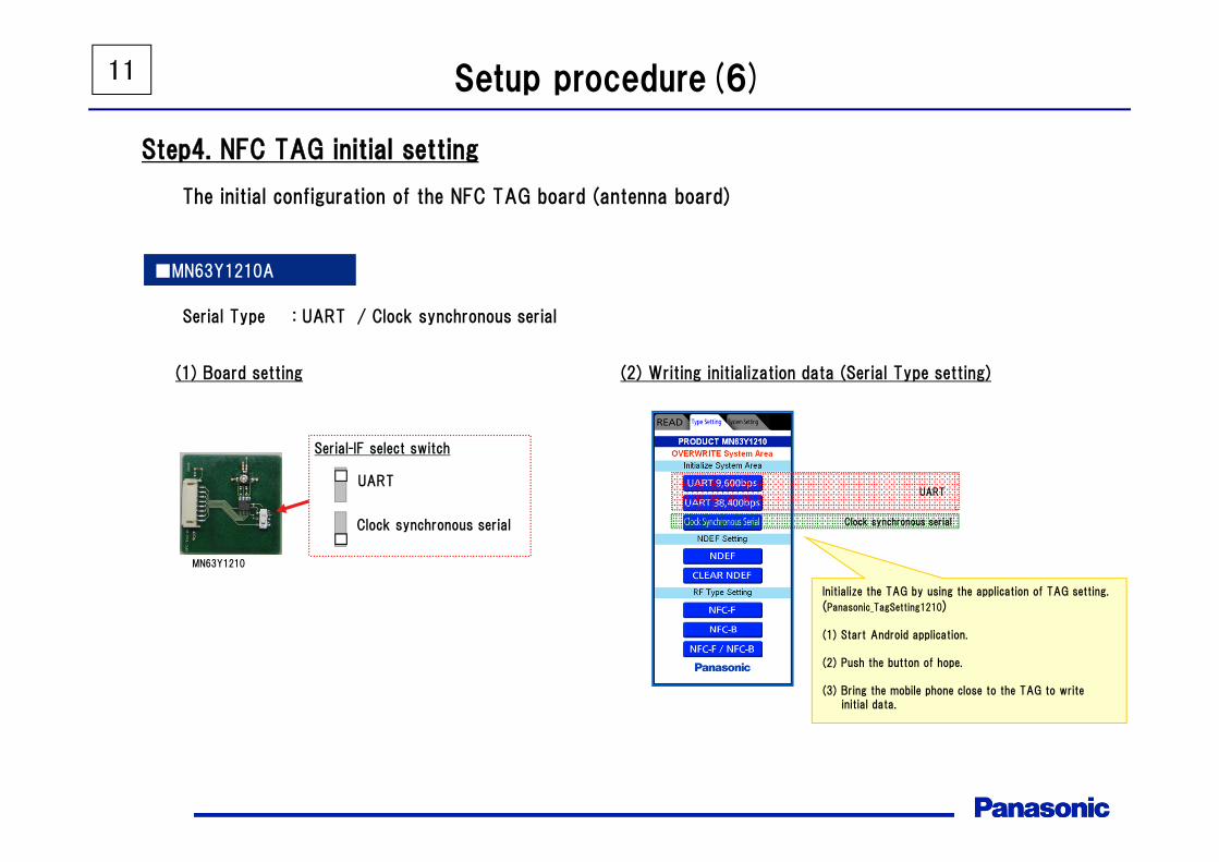
Step4. NFC TAG initial setting
The initial configuration of the NFC TAG board (antenna board)
Serial Type : UART / Clock synchronous serial
(1) Board setting
■MN63Y1210A
MN63Y1210
(2) Writing initialization data (Serial Type setting)
UART
Clock synchronous serial
Initialize the TAG by using the application of TAG setting.
(Panasonic_TagSetting1210)
(1) Start Android application.
(2) Push the button of hope.
(3) Bring the mobile phone close to the TAG to write initial data.
UART
Clock synchronous serial
Serial-IF select switch
12 Setup procedure(7)
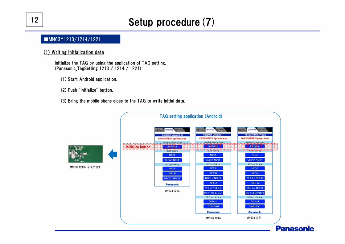
■MN63Y1213/1214/1221
(1) Writing initialization data
MN63Y1213/1214/1221
MN63Y1213
MN63Y1214
TAG setting application (Android)
Initialize the TAG by using the application of TAG setting.(Panasonic_TagSetting 1213 / 1214 / 1221)
(1) Start Android application.
(2) Push "initialize" button.
(3) Bring the mobile phone close to the TAG to write initial data.
XX
Initialize button
MN63Y1221
13 Setup procedure(8)
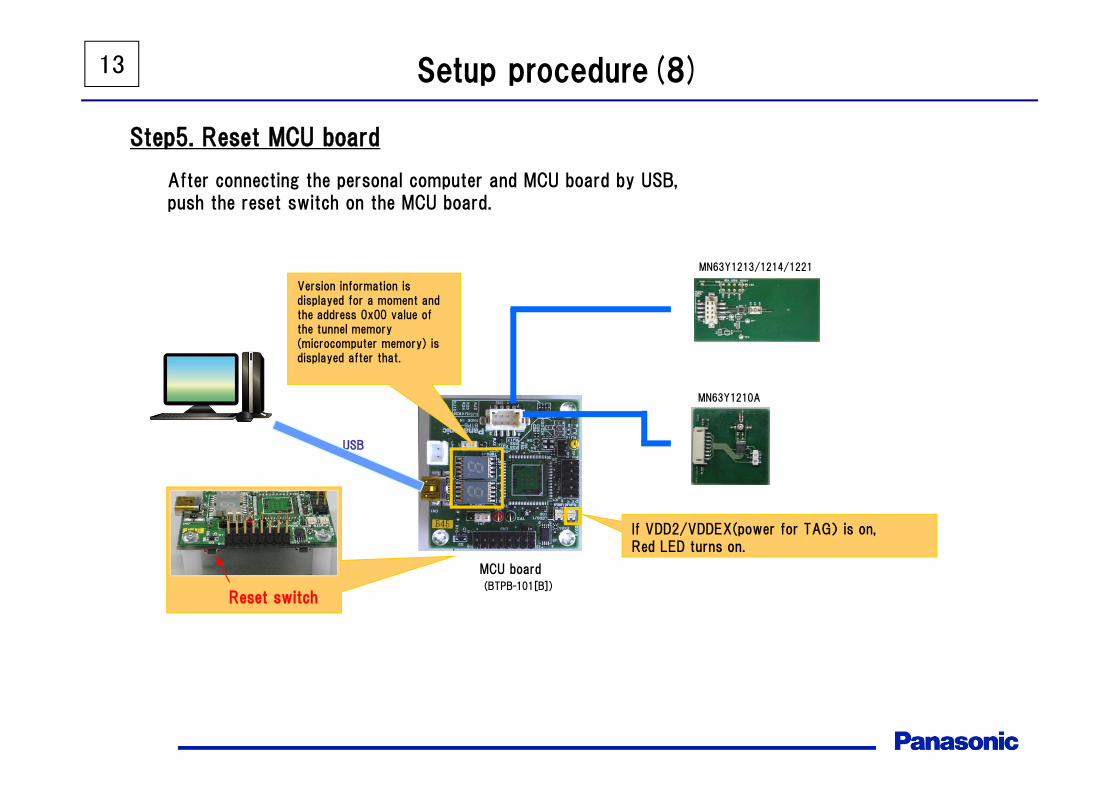
Step5. Reset MCU board
After connecting the personal computer and MCU board by USB,push the reset switch on the MCU board.
MCU board(BTPB-101[B])
USB
Version information is displayed for a moment and the address 0x00 value of the tunnel memory(microcomputer memory) is displayed after that.
If VDD2/VDDEX(power for TAG) is on,Red LED turns on.
Reset switch
MN63Y1210A
MN63Y1213/1214/1221

14 Setup procedure(9)
If you do the file transfer by WiFi, start the PC software as administrator.※In order to use Microsoft Windows7 standard function "Virtual Wi-Fi (wireless hosted network)",
you must start the application as administrator.
When you start the PC software as administrator, the Security Alert screen will appear.If you perform the file transfer by WiFi, check both of the check boxes.
※This is necessary to perform the data communication with mobile phones.
Check both of the check boxes
In case of performing the file transfer by WiFi
Click right button of the mouse on the software icon,and select [Run as administrator] in the menu.
Step6. Start PC software
This procedure is necessary forperforming a file transfer by WiFi

15
Development kit usage
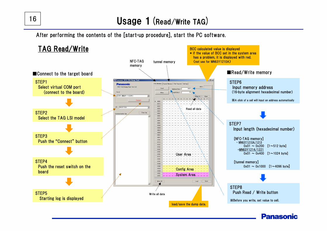
16 Usage 1(Read/Write TAG)
STEP1Select virtual COM port
(connect to the board)
STEP3Push the “Connect” button
STEP4Push the reset switch on the board
STEP5Starting log is displayed
■Connect to the target board
STEP6Input memory address(16-byte alignment hexadecimal number)
※A click of a cell will input an address automatically
STEP7Input length (hexadecimal number)
[NFC-TAG memory]・ MN63Y1210A/1213
0x01 ~ 0x200 [1~512 byte]・MN63Y1214/1221
0x01 ~ 0x400 [1~1024 byte]
[tunnel memory]0x01 ~ 0x1000 [1~4096 byte]
STEP8Push Read / Write button
※Before you write, set value to cell.
■Read/Write memory
STEP2Select the TAG LSI model
User Area
Config Area
System Area
load/save the dump data.
Write all data
Read all data
NFC-TAGmemory
tunnel memory
TAG Read/Write BCC calculated value is displayed* if the value of BCC set in the system area
has a problem, it is displayed with red.(not use for MN63Y1210A)
After performing the contents of the [start-up procedure], start the PC software.

17 Usage 2(file transfer1)
Start the PC software, and connect to the MCU board(See previous page)
Connect MCU board to PC by USB
STEP 1
STEP 2
Push the reset switch on the MCU board (reset the board)
STEP 3
Reset switch
Start the file transfer application on mobile phone and select the file that you want to transfer to the PC
STEP 4Androidfile transfer application(TagFileTx)
STEP 5
Touch the tag by the mobile phone
STEP 6
Screen of the PC software switches automatically, and file transfer is started (See next page)
18
file transfer screen
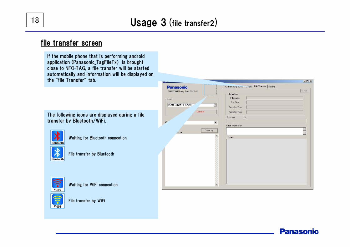
If the mobile phone that is performing android application (Panasonic_TagFileTx) is brought close to NFC-TAG, a file transfer will be started automatically and information will be displayed on the “file Transfer” tab.
The following icons are displayed during a file transfer by Bluetooth/WiFi.
Waiting for Bluetooth connection
File transfer by Bluetooth
Waiting for WiFi connection
File transfer by WiFi
Usage 3(file transfer2)

19
■Tag power supplyControl the power supply to the tag from the microcomputer
always : power supply to the tag alwaysnot always : power supply to the tag when necessary
■Communication log modeset of log displayEnable Log (All) : enable all logDisable Log (except File Transfer) : enable only necessary logs for
file transferDisable Log : disable all log
■WiFi adapter infoDisplay the information of WiFi adapter (PC will be the access point)SSID : SSID of the access pointIP Address : IP address of the access point
Check Adapter : update the information of WiFi adapter
Usage 4(setting)

20 (Supplement) Bluetooth file transfer sequence
② Start BluetoothStart Bluetooth in server modeand wait connection from PC
(use RFCOMM protocol)
Antenna
Seria
l-USB
converter
8bit M
CU
NFCTAG
UART
Serial-IFUSB
mobile phone(with NFC controller)NFC-TAG boardMCU boardPC
Android application
312500bps
①Write data into the tunnel memory
(Start Command & Bluetooth MAC address)
③Connection request between PC and mobile phone by Bluetooth
(use RFCOMM protocol and Bluetooth MAC address of the mobile phone)
⑤Send file data
④Connection OK
PC software
Touch the tag by the mobile phone

21
Antenna
Seria
l-USB
converter
8bit M
CU
NFCTAG
UART
Serial-IFUSB
mobile phone(with NFC controller)NFC-TAG boardMCU boardPC
Android application
312500bps
③ Connection request to the access point from the mobile phone by WiFi
④ Connection OK
① Start WiFi access point
② Write data into the tunnel memory
(Start Command & WiFi MAC address)
Start WiFi access point andwait for the connection from the mobile phone.
⑤Send file data
PC software
Touch the tag by the mobile phone
(Supplement) WiFi file transfer sequence

22 Revision History
Version Date Comments
2.00 2012/11/22 Initial edition
2.20 2013/09/05 Version up of PC software/Android application
2.21 2013/10/03 add MN63Y1213
2.30 2013/10/25 Version up of PC software
2.41 2014/10/31 add MN63Y1214/1217, support WiFi file transfer
2.42 2015/01/08 Version up of Microcomputer software / PC software / Android software
2.50 2015/03/16 add MN63Y1219
2.60 April 6, 2016 Added MN63Y1221. Modified some explanations.
2.70 May 11, 2016 Deleted MN63Y1208, MN63Y1217 and MN63Y1219.

Request for your special attention and precautions in using the technical information andsemiconductors described in this book
(1) If any of the products or technical information described in this book is to be exported or provided to non-residents, the laws andregulations of the exporting country, especially, those with regard to security export control, must be observed.
(2) The technical information described in this book is intended only to show the main characteristics and application circuit examplesof the products. No license is granted in and to any intellectual property right or other right owned by Panasonic Corporation or anyother company. Therefore, no responsibility is assumed by our company as to the infringement upon any such right owned by anyother company which may arise as a result of the use of technical information described in this book.
(3) The products described in this book are intended to be used for general applications (such as office equipment, communicationsequipment, measuring instruments and household appliances), or for specific applications as expressly stated in this book.Consult our sales staff in advance for information on the following applications: Special applications (such as for airplanes, aerospace, automotive equipment, traffic signaling equipment, combustion equipment,
life support systems and safety devices) in which exceptional quality and reliability are required, or if the failure or malfunction ofthe products may directly jeopardize life or harm the human body.
It is to be understood that our company shall not be held responsible for any damage incurred as a result of or in connection withyour using the products described in this book for any special application, unless our company agrees to your using the products inthis book for any special application.
(4) The products and product specifications described in this book are subject to change without notice for modification and/or improve-ment. At the final stage of your design, purchasing, or use of the products, therefore, ask for the most up-to-date Product Standards in advance to make sure that the latest specifications satisfy your requirements.
(5) When designing your equipment, comply with the range of absolute maximum rating and the guaranteed operating conditions(operating power supply voltage and operating environment etc.). Especially, please be careful not to exceed the range of absolutemaximum rating on the transient state, such as power-on, power-off and mode-switching. Otherwise, we will not be liable for anydefect which may arise later in your equipment.Even when the products are used within the guaranteed values, take into the consideration of incidence of break down and failuremode, possible to occur to semiconductor products. Measures on the systems such as redundant design, arresting the spread of fire orpreventing glitch are recommended in order to prevent physical injury, fire, social damages, for example, by using the products.
(6) Comply with the instructions for use in order to prevent breakdown and characteristics change due to external factors (ESD, EOS,thermal stress and mechanical stress) at the time of handling, mounting or at customer's process. When using products for whichdamp-proof packing is required, satisfy the conditions, such as shelf life and the elapsed time since first opening the packages.
(7) This book may be not reprinted or reproduced whether wholly or partially, without the prior written permission of our company.
No.020210