development of a 500 watt high temperature … · development of a 500 watt high temperature...
TRANSCRIPT

Development of a 500 Watt High Development of a 500 Watt High Temperature Thermoelectric Temperature Thermoelectric
GeneratorGenerator
S. Ayres, L. Bell, D. Crane, J. LaGrandeur
5, August, 2009
BSST Proprietary and Confidential

Waste Heat Recovery SystemsWaste Heat Recovery SystemsGlobal CO2
emission reduction goals requires greater fuel
economy while customers want more auxiliary features that
consume electrical energy.
Most near term CO2
reduction opportunities have been already
identified and scheduled for introduction.
Demand for comfort and features requires sources of electric power
that do not degrade performance or reduce fuel economy.
A growing percentage of customers are demanding greener vehicles.
Waste heat is an untapped source for electric power that could
reduce CO2
3% ‐
7% near term and 5% ‐
10% longer term under
typical driving conditions.
To address these challenges the US DOE started programs with four
companies in Q4 2004. BSST is leading a team including BMW, Ford
Motor Company and Visteon.
25 August, 2009 Deer 2009

BSST Waste Heat Recovery Program BSST Waste Heat Recovery Program OverviewOverview
The program is organized into 5 development phases:
Phase 1
(Q3 04 thru Q2 05) A system architecture was created and
bumper to bumper model created using ADVISOR. Initial system
FE savings were shown to reach 12%
Phase 2
(Q3 05 thru Q4 06) Key subsystems (Primary Exhaust Gas
Heat Exchanger, Thermoelectric Generator Module TGM), Power
Conversion Electronics) were built and tested. BMW converted the
bumper to bumper model to a Gamma Technologies modeling
platform
35 August, 2009 Deer 2009

BSST Waste Heat Recovery Program BSST Waste Heat Recovery Program OverviewOverview
Phase 3
(Q1 07 thru Q3 08) Low and high temp TEGs were built
and tested with other key subsystems:
−
A BiTe TGM was built and tested demonstrating > 500 watts
electrical power output.
−
A high temperature TEG was built and tested in Q4 2008 showing
greater than 100 watts of power
−
The Waste Heat Recovery System was operated on a test bench
using a hot air in Q3 2008
−
The single layer high temp TEG was installed on a single cylinder
engine at Ford and tested on an engine dyno in Q4 2008
Phase 4
(Q4 2008 – Q3 2009) A 500 watt high temperature TEG
will be integrated and tested with BMW’s in line 6 cylinder engine
on an engine dynamometer at the NREL Federal Laboratory
Phase 5
(Q3 2009‐Q4 2009) Integration into vehicles at BMW and
Ford45 August, 2009 Deer 2009

Estimated Fuel Economy BenefitsEstimated Fuel Economy Benefits
CycleAve. Cycle Power
(W)% FE Increase
Highway 348 1.5
City 91 1.2
5
0
1
2
3
4
5
6
Red
uction
in fuel con
sumption (%
)
after flange, without exhaust system insulation
after flange, with exhaust system insulation
pre‐tube, with exhaust system insulation
BMW 3l turbocharged 5 passenger sedan. ZT average
= 0.85
Ford 2.5l Hybrid SUV
To minimize exhaust back pressure, the flow was limited to 40 g/s
Additional performance gains can be realized with advanced materials and better system optimization
5 August, 2009 Deer 2009

6
BSST TE EngineBSST TE Engine
BSST stack design allows:Optimum compressive loads for thermal and
electrical interfaces
Tailored n and p type element geometries for
highest efficiency
TE material reduction of 75% or more
5 August, 2009 Deer 2009

Phase 3Phase 3 Low Temp 500W TEGLow Temp 500W TEG
n-type Bi2Te3n-type Bi2Te3
160 mm
TE Circuit (Bi2Te3 subassemblies)
160 mm160 mm
TE Circuit (Bi2Te3 subassemblies)
500W Generator (Delta T = 207°C)
0
100
200
300
400
500
600
0 5 10 15 20 25 30 35 40Current (Amps)
Pow
er (W
atts
)
0
10
20
30
40
50
60
Vol
tage
(V)
PowerV-I
5 Sept 2007
160 mm
75 August, 2009 Deer 2009

High Temperature TEG Design SummaryHigh Temperature TEG Design Summary
•
Hot side heat exchanger redesigned for 5000C exhaust gas (BiTe TEG used liquid heat
exchangers with 2000C oil)
•
Three different TE subassemblies designed to match exhaust gas temperature gradient in the
direction of flow to provide maximum TE material performance
•
TEG thermal and electrical interfaces modified to withstand high temperature environment
85 August, 2009 Deer 2009

9
100 Watt High Temperature TEG100 Watt High Temperature TEG
•
Counter flow
design
•
Three
configurations of
TE subassemblies
designed to
match the
temperature
gradient in the
heat exchanger
for maximum TE
performance
TE Bank 1High Temp
TE Bank 2Medium Temp
TE Bank 3Low Temp
Gas flow Coolant flow
5 August, 2009 Deer 2009

Prototype Heat ExchangersPrototype Heat ExchangersHot side:
Stainless steel brazed
construction with wavy fin
Diamond surface coating
for electrical isolation
Cold side:
Lytron off the shelf
aluminum cold plate
Surface finish: clear
anodized for electrical
isolation
105 August, 2009 Deer 2009

Subscale High Temp TEG TestSubscale High Temp TEG Test
11
0.0
10.0
20.0
30.0
40.0
50.0
60.0
70.0
80.0
90.0
100.0
110.0
120.0
130.0
140.0
0 5 10 15 20 25 30 35 40
power (W
)
current (A)
High Temperature Segmented TEG Single Layer Tests(water inlet temperature = 25C, water flow = 10 lpm, air flow = 45 cfm)
(surrounding environment ‐‐ air < = 300C, argon > 300C)
air inlet temp = 100C
air inlet temp = 150C
air inlet temp = 200C
air inlet temp = 230C
air inlet temp = 250C
air inlet temp = 300C
air inlet temp = 350C
air inlet temp = 400C
air inlet temp = 450C
air inlet temp = 500C
air inlet temp = 550C
air inlet temp = 600C
High Temp. TEG Installation Engine Installed in Dyno
Test results for single layer high temp TEG
5 August, 2009 Deer 2009

Phase 4 Full Scale TEGPhase 4 Full Scale TEG
12
•
TEG redesigned to cylindrical configuration to improve packaging and reduce thermal stresses
•
Exhaust bypass integrated through center of heat exchanger
•
Allows for greater output with single gas & coolant connections
5 August, 2009 Deer 2009

TEG CrossTEG Cross‐‐Sectional ViewSectional View
135 August, 2009 Deer 2009

Exhaust Flow ControlExhaust Flow Control
•Under normal operation, valve is closed
and exhaust gas flows through the heat
exchanger assembly
•At very high mass flow rates, high
exhaust gas temperatures and under
high coolant heat flux loads, some or all
of the exhaust gas flows through the
central bypass region valve in exhaust
streams
•Valve can have proportional control to
optimize system performance. Flow
between the two regions is selected
based on data processed by TEG and
engine control systems
145 August, 2009 Deer 2009

Hot Side Shunt DesignHot Side Shunt Design•
Continuous ring hot side shunt
assembly has groups of TE
elements in parallel. Each ring
produces high current, low
voltage. Generally 10‐20 rings are
connected electrically in series
•
Electrically isolated ring segments
(with gaps) operate at higher
voltage and lower current. Entire
array of segments can be
connected electrically in series
•
With either arrangement TE
elements are in a series parallel
arrangement, significantly
increasing reliability and design
robustness165 August, 2009 Deer 2009
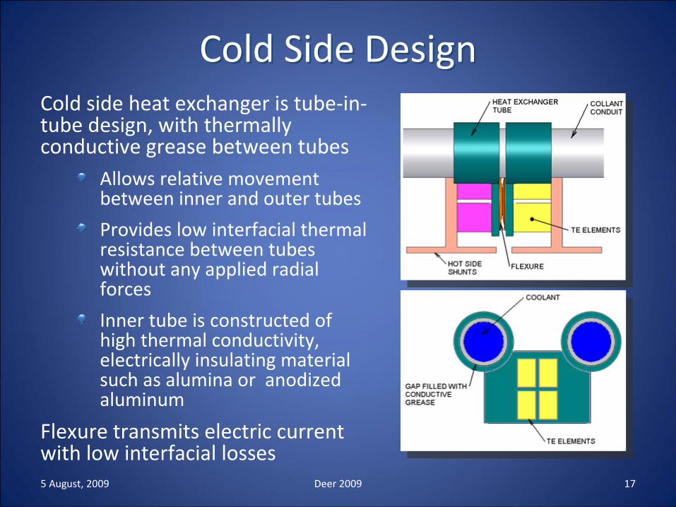
Cold Side DesignCold Side DesignCold side heat exchanger is tube‐in‐
tube design, with thermally
conductive grease between tubesAllows relative movement
between inner and outer tubes
Provides low interfacial thermal
resistance between tubes
without any applied radial
forces
Inner tube is constructed of
high thermal conductivity,
electrically insulating material
such as alumina or anodized
aluminum
Flexure transmits electric current
with low interfacial losses175 August, 2009 Deer 2009

Phase 4 TEGPhase 4 TEG
•Cylindrical TEG currently under
construction
•Will be tested on
bench at BSST, then
shipped to NREL for
testing with BMW
inline 6 cylinder engine
on dyno
185 August, 2009 Deer 2009

Additional Aspects of New TEG DesignAdditional Aspects of New TEG Design•Cold side tubes connected to cold shunts with grease,
but without the need for additional thermal compression
•CTE mismatch and TE element compression in the electrical flow direction handled by having a split cold
shunt
•Coating applied to the hot side heat exchanger to provide thermally conductive electrical insulation
•Different electrical circuits introduced for each bank•Hot side fin material is SST clad copper
195 August, 2009 Deer 2009

Summary and Further WorkSummary and Further Work
•
A low temperature TEG has been built and tested providing over 500 watts electric power at a ∆T of 2000C
•
A subscale single layer high temperature TEG has been built and tested on bench and engine dyno
•
A new design cylindrical TEG is currently being assembled for testing to begin in Q3
•
A low temperature TEG has been tested on a diesel engine producing 88W in vehicle.
205 August, 2009 Deer 2009

AcknowledgementsAcknowledgements
John Fairbanks and the US DOE Office of Vehicle Technologies (OVT)
Aaron Yokum
and Carl Maronde
of the DOE NETL
Andreas Eder and Boris Mazar
of BMW
Steve Newton of Visteon
Clay Maranville
of Ford
215 August, 2009 Deer 2009