development of a alkyclean solid acid catalyst solid...
TRANSCRIPT
-1-
AlkyClean����
Solid Acid Alkylation
October 6, 2006
Development of a Solid Acid Catalyst Alkylation Process
TD
C_2
006
-2
AlkyClean���� solid acid alkylation
Presentation Outline
� Introduction
� Process Development
� Demonstration Unit
� Economic Benchmarking
� Summary
TD
C_2
006
-3
AlkyClean process for gasoline alkylate
� Mandate: Cleaner fuels and “Greener” refining processes
� Answer: Alkylate = Clean Gasoline High RON & MON, virtually no olefins, aromatics or sulfur, low RVP
� Problem: Safety, environmental and reliability issues associated with current liquid acid technologies
� Challenge: Develop and demonstrate an environmentally friendly and competitive Solid Acid Catalyst (SAC) technology to replace HF and H2SO4 technologies
Introduction
TD
C_2
006
-4
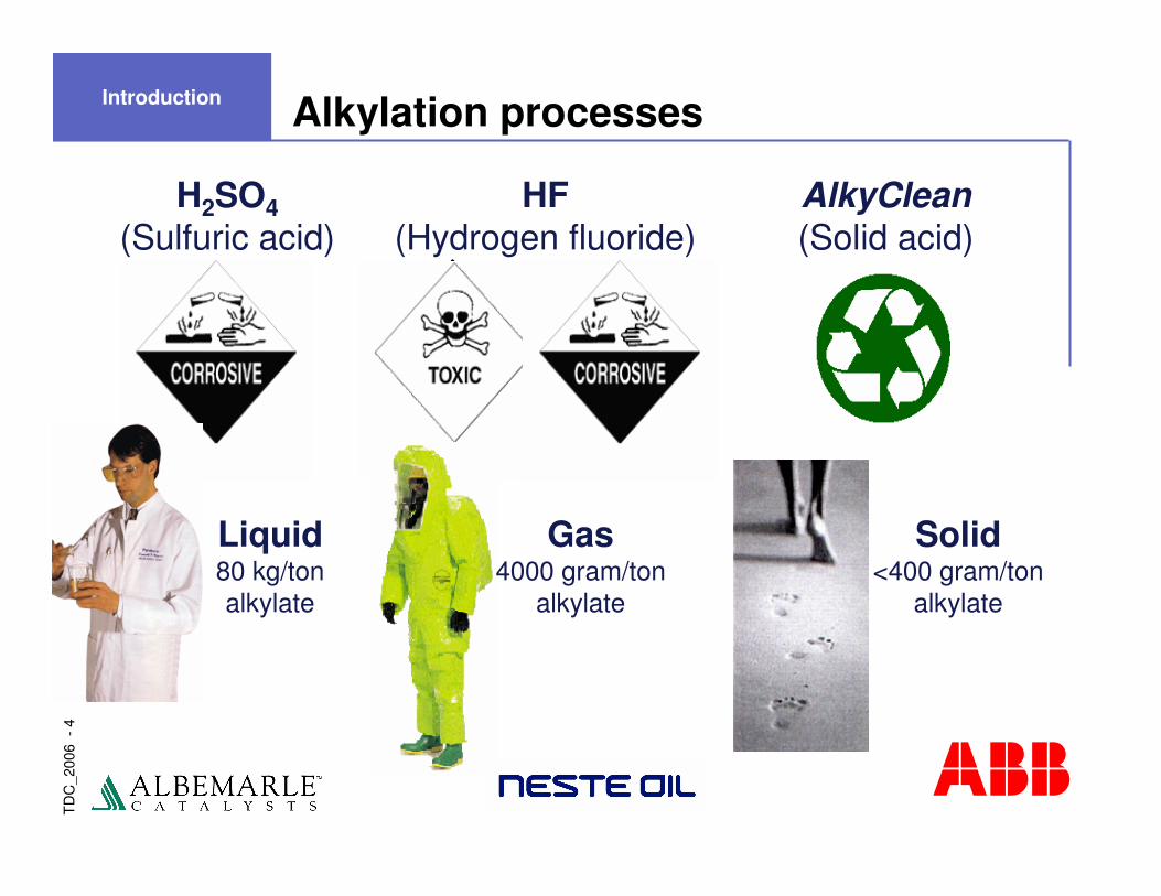
Alkylation processes
H2SO4(Sulfuric acid)
Liquid80 kg/tonalkylate
HF(Hydrogen fluoride)
Gas4000 gram/ton
alkylate
AlkyClean(Solid acid)
Solid<400 gram/ton
alkylate
Introduction

Localized risk during use
� Measured by risk analyses (experimental data and individual risk measurement)
Alky
HF
H2SO4
Introduction

TD
C_2
006
-6
Alkylation market drivers
� Economic driver – increases quantity of gasoline
� Environmental driver – high quality RFG blend stock� No olefins, aromatics, or S
� Low volatility (“RVP”)
� High octane, RON & MON
� MTBE replacement
Introduction
TD
C_2
006
-7
���������������������������� ����������
� �����
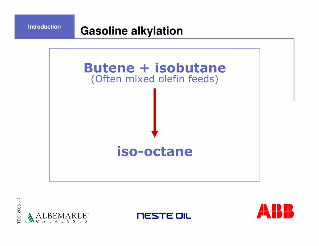
Gasoline alkylationIntroduction
TD
C_2
006
-8
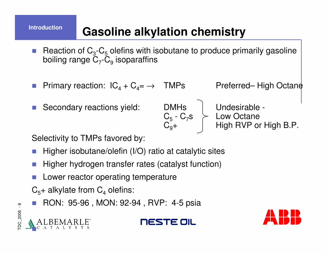
Gasoline alkylation chemistry� Reaction of C3-C5 olefins with isobutane to produce primarily gasoline
boiling range C7-C9 isoparaffins
� Primary reaction: IC4 + C4= → TMPs Preferred– High Octane
� Secondary reactions yield: DMHs Undesirable -C5 - C7s Low OctaneC9+ High RVP or High B.P.
Selectivity to TMPs favored by:
� Higher isobutane/olefin (I/O) ratio at catalytic sites
� Higher hydrogen transfer rates (catalyst function)
� Lower reactor operating temperature
C5+ alkylate from C4 olefins:
� RON: 95-96 , MON: 92-94 , RVP: 4-5 psia
�
Introduction
TD
C_2
006
-9
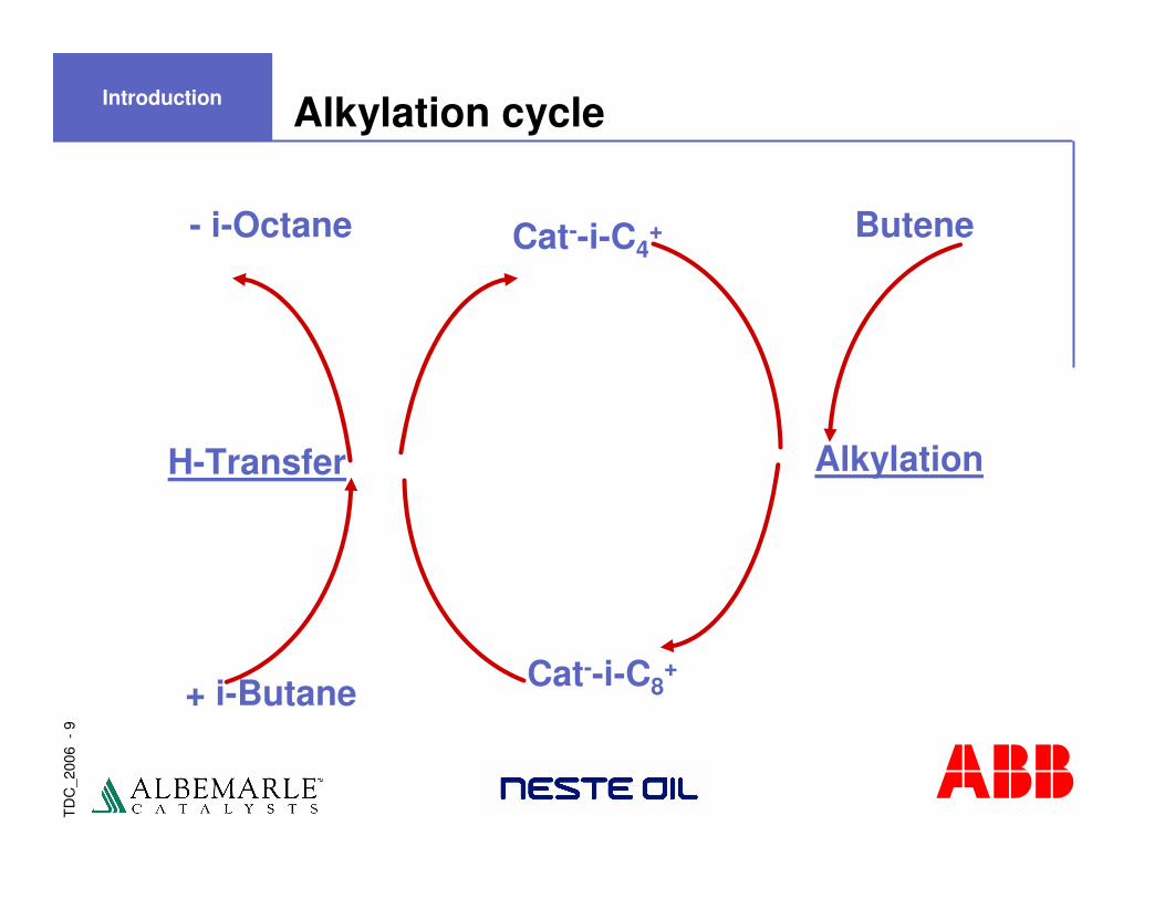
Alkylation cycle
Cat--i-C8+
Cat--i-C4+- i-Octane
+ i-Butane
Butene
AlkylationH-Transfer
Introduction
TD
C_2
006
-10
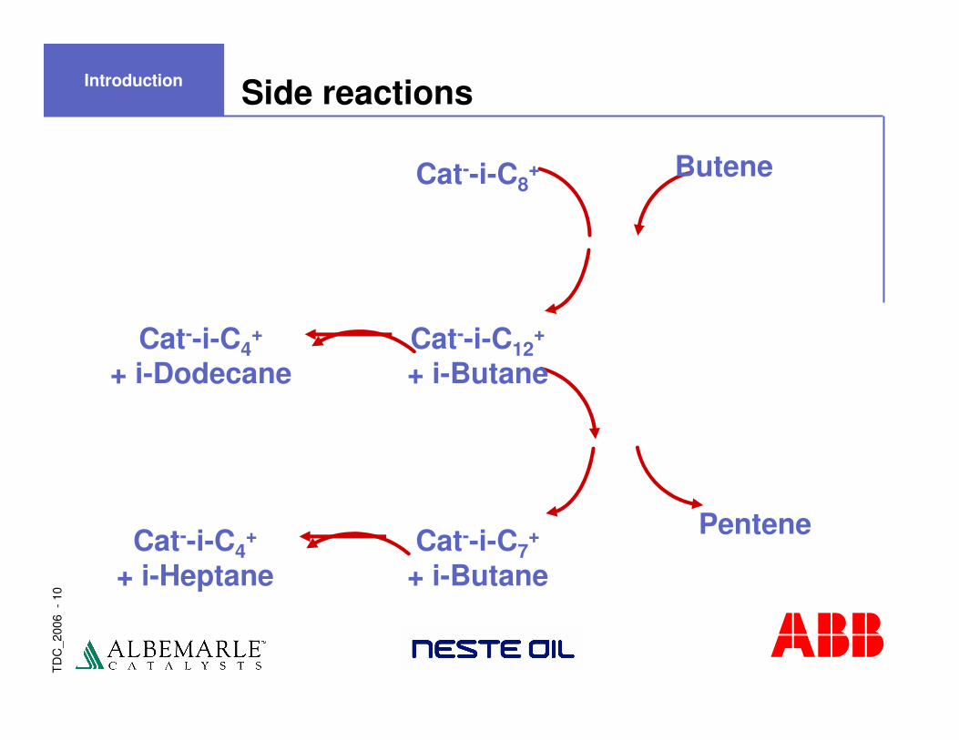
Side reactions
Cat--i-C8+
Cat--i-C12+
+ i-Butane
Cat--i-C7+
+ i-ButaneCat--i-C4
+
+ i-Heptane
Cat--i-C4+
+ i-Dodecane
Butene
Pentene
Introduction
TD
C_2
006
-11
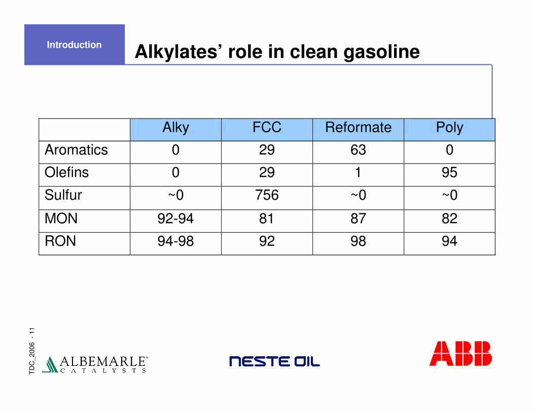
Alkylates’ role in clean gasolineIntroduction
Alky FCC Reformate Poly
Aromatics 0 29 63 0
Olefins 0 29 1 95
Sulfur ~0 756 ~0 ~0
MON 92-94 81 87 82
RON 94-98 92 98 94

TD
C_2
006
-12
Octane yield comparisonIntroduction
Process Yield Vol/Prod/Vol Olefin Used
RON Volume per Volume of Olefin Used
MON Volume per Volume of Olefin Used
Alkylation C4= 1.7 163 158 Alkylation C5= 1.8 163 160 MTBE 1.25 144 121 Dimerization 0.85 83 79 Cat. Poly. 0.8 78 66
TD
C_2
006
-13
AlkyClean catalyst
Features
� True solid acid: no halogens or volatile components
� Properties tailored to yield high quality alkylate, with maximized activity and stability
� Robust: low sensitivity towards feedstock composition variation and common impurities
Successful commercial scale-up
� Successful commercial trial production of the original catalyst in 2002 and of a new optimized version in 2004
Introduction
TD
C_2
006
-14
Joint venture development progression
� ABB Lummus Global � Initiated R&D effort 1994
� ABB Lummus Global and Albemarle Catalysts� Cooperation since 1996
� Neste Oil � Joined the team in 2001 for technology demonstration
Introduction
TD
C_2
006
-15
Development and demonstration status
� Bench scale development work completed
� AlkyClean catalyst manufactured at commercial scale
� Demonstration unit constructed and initially operated during 2002-2003, proving key technology aspects and process operability
� Further bench scale effort focused on improvement of catalyst/ process performance and resulting economics
� Successfully completed demonstration of these catalyst and processing improvements in 2004
� Technology offered for license beginning 2005
� Bench-scale work continues to expand data base and support next generation catalyst
Introduction
TD
C_2
006
-16
AlkyClean���� solid acid alkylation
Presentation Outline
� Introduction
� Process Development
� Demonstration Unit
� Economic Benchmarking
� Summary
TD
C_2
006
-17
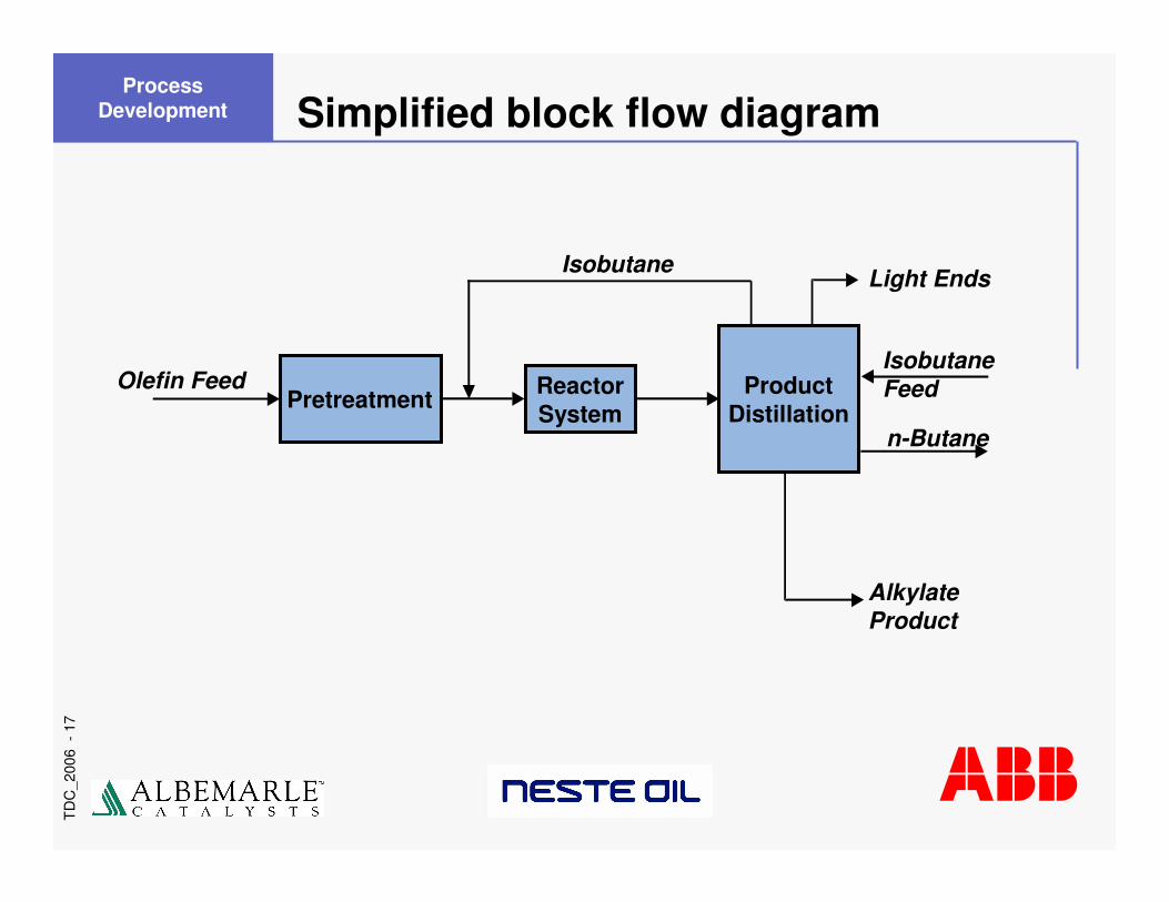
Simplified block flow diagram
Pretreatment Product Distillation
IsobutaneFeed
Isobutane Light Ends
AlkylateProduct
n-Butane
Process Development
Reactor System
Olefin Feed
TD
C_2
006
-18
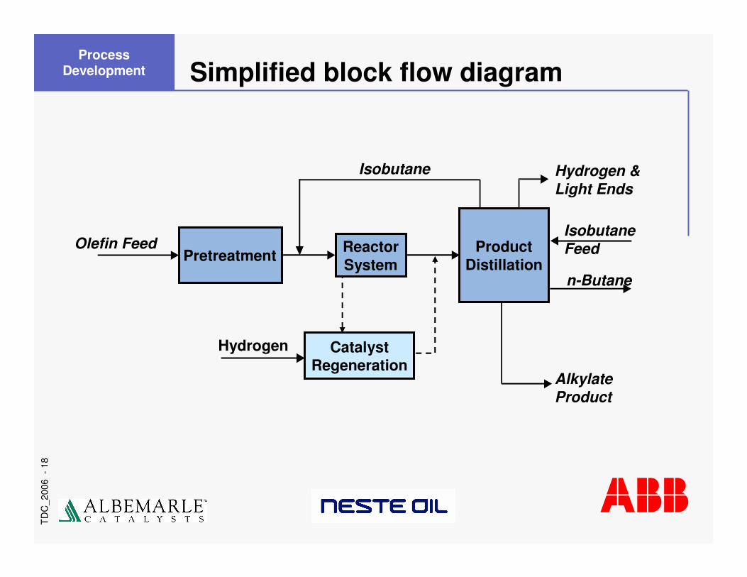
Simplified block flow diagram
Olefin FeedPretreatment Product
Distillation
IsobutaneFeed
Isobutane Hydrogen &Light Ends
AlkylateProduct
n-Butane
Process Development
Reactor System
Catalyst Regeneration
Hydrogen
TD
C_2
006
-19
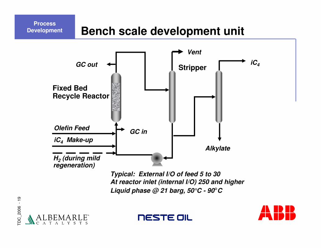
Fixed BedRecycle Reactor
Stripper
Alkylate
Olefin Feed
iC4 Make-up
H2 (during mild regeneration)
iC4
GC in
GC out
Vent
Typical: External I/O of feed 5 to 30At reactor inlet (internal I/O) 250 and higherLiquid phase @ 21 barg, 50°C - 90°C
Bench scale development unitProcess
Development
TD
C_2
006
-20
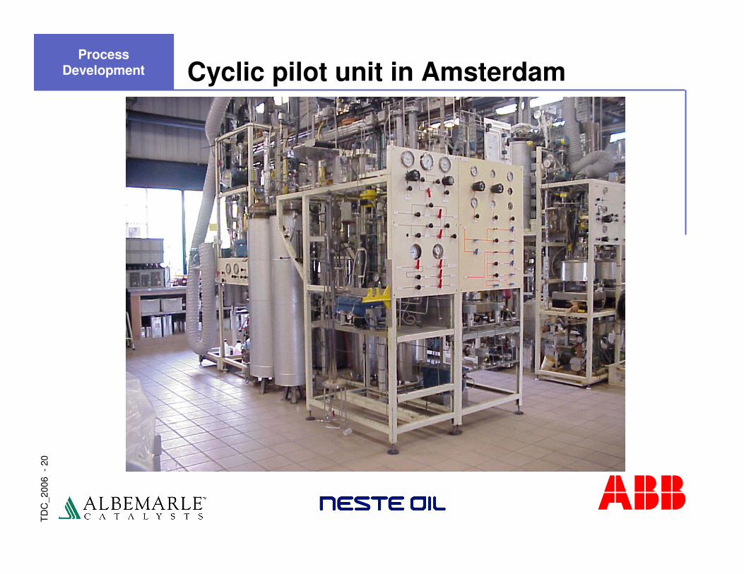
Cyclic pilot unit in AmsterdamProcess
Development

TD
C_2
006
-21
0.0
0.1
0.2
0.3
0.4
0.5
0.6
0 2 4 6 8 10 12 14 16Tim e (hrs)
%wt
IN OUT
Olefin concentration versus timeProcess
Development
TD
C_2
006
-22
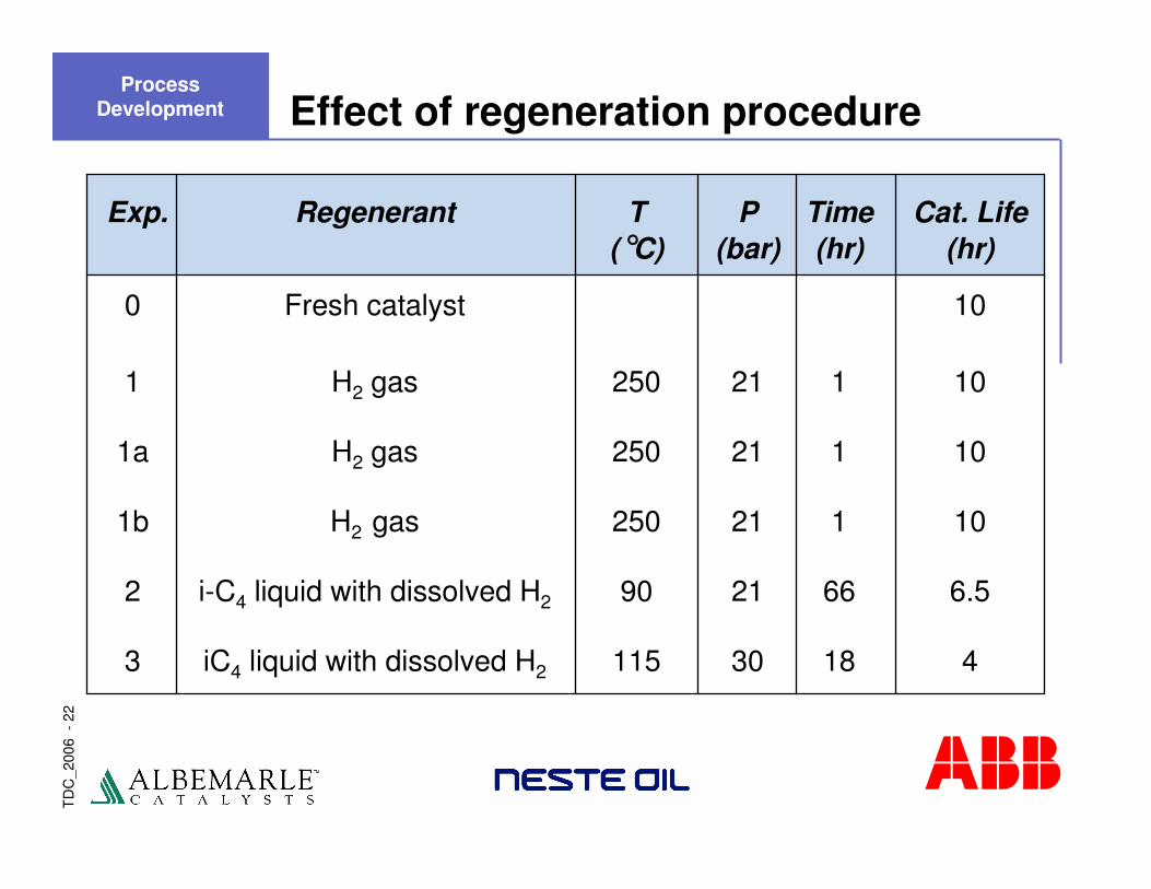
Effect of regeneration procedure
Exp. Regenerant T P Time Cat. Life(°C) (bar) (hr) (hr)
0 Fresh catalyst 10
1 H2 gas 250 21 1 10
1a H2 gas 250 21 1 10
1b H2 gas 250 21 1 10
2 i-C4 liquid with dissolved H2 90 21 66 6.5
3 iC4 liquid with dissolved H2 115 30 18 4
Process Development
TD
C_2
006
-23
NEW TITLE
� Regeneration at 250°C in H2 (gas phase) completely recovers activity and selectivity
� Regeneration with i-C4 and dissolved H2 (liquid phase) not successful
Conclusions – Regeneration after olefin breakthrough
Next – Investigated short cycle mild regeneration
� Alternating periods of alkylation and liquid phase regeneration with i-C4 and dissolved H2
� Regeneration occurs prior to significant olefin breakthrough
Process Development

TD
C_2
006
-24
55°C60°C65°C70°C80°C
92
93
94
95
96
97
98
99
100
0 22 44 66 88 110 132 154 176 198 220
Time (hrs)
RO
N
IN OUT TEMP
RON versus temperature
Cyclic Run Optimized Catalyst –stable even at low T
Process Development
TD
C_2
006
-25
Process key – cyclic reactor operation
Short cycle alkylation / mild regeneration
� Alternating periods of alkylation and liquid phase mild regeneration with i-C4 and dissolved H2
� Seamless – no change in operating conditions; hydrogen injection substituted for olefin feed
� Mild regeneration is pre-emptive – occurs prior to excessive deactivation and formation of ‘hard’ coke
� Allows for continuous operation and maintenance of product quality
� First patent granted in 1999 – US 5,986,158
Process Development
TD
C_2
006
-26
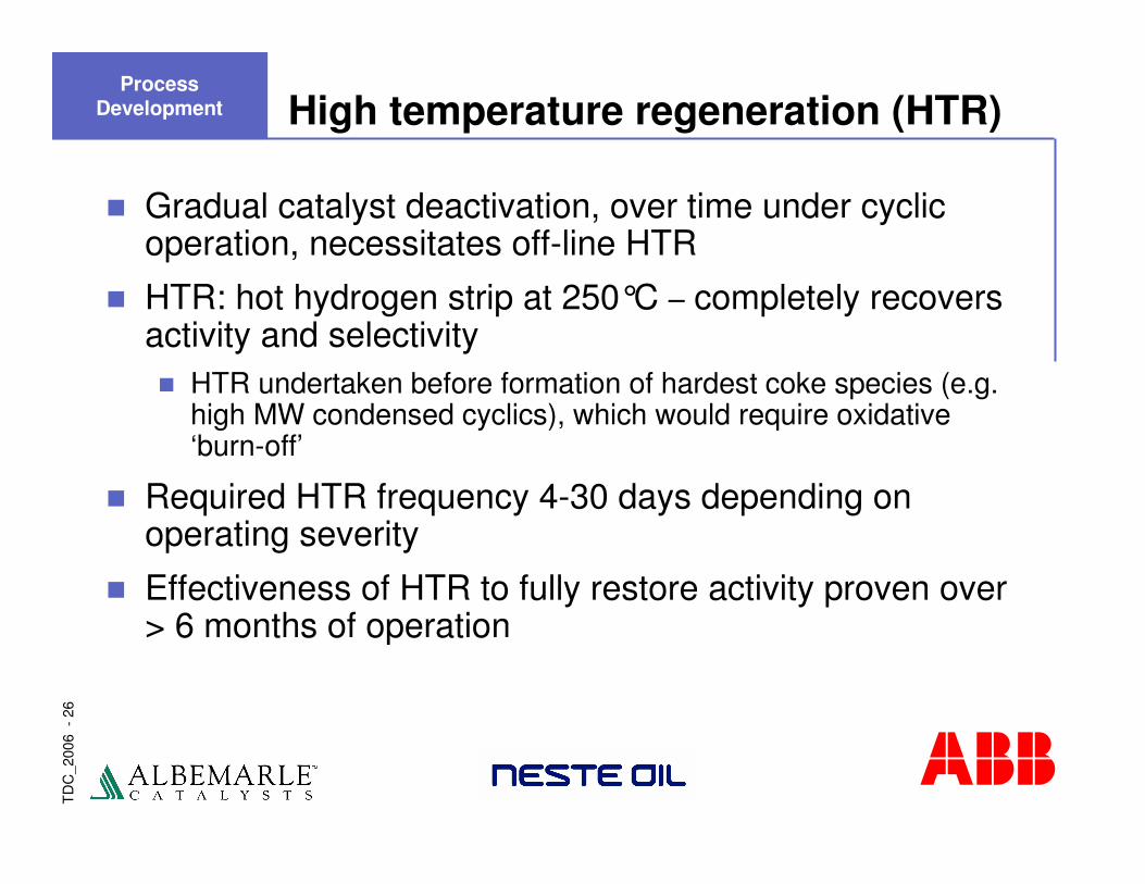
High temperature regeneration (HTR)
� Gradual catalyst deactivation, over time under cyclic operation, necessitates off-line HTR
� HTR: hot hydrogen strip at 250°C – completely recovers activity and selectivity� HTR undertaken before formation of hardest coke species (e.g.
high MW condensed cyclics), which would require oxidative ‘burn-off’
� Required HTR frequency 4-30 days depending on operating severity
� Effectiveness of HTR to fully restore activity proven over > 6 months of operation
Process Development
TD
C_2
006
-27
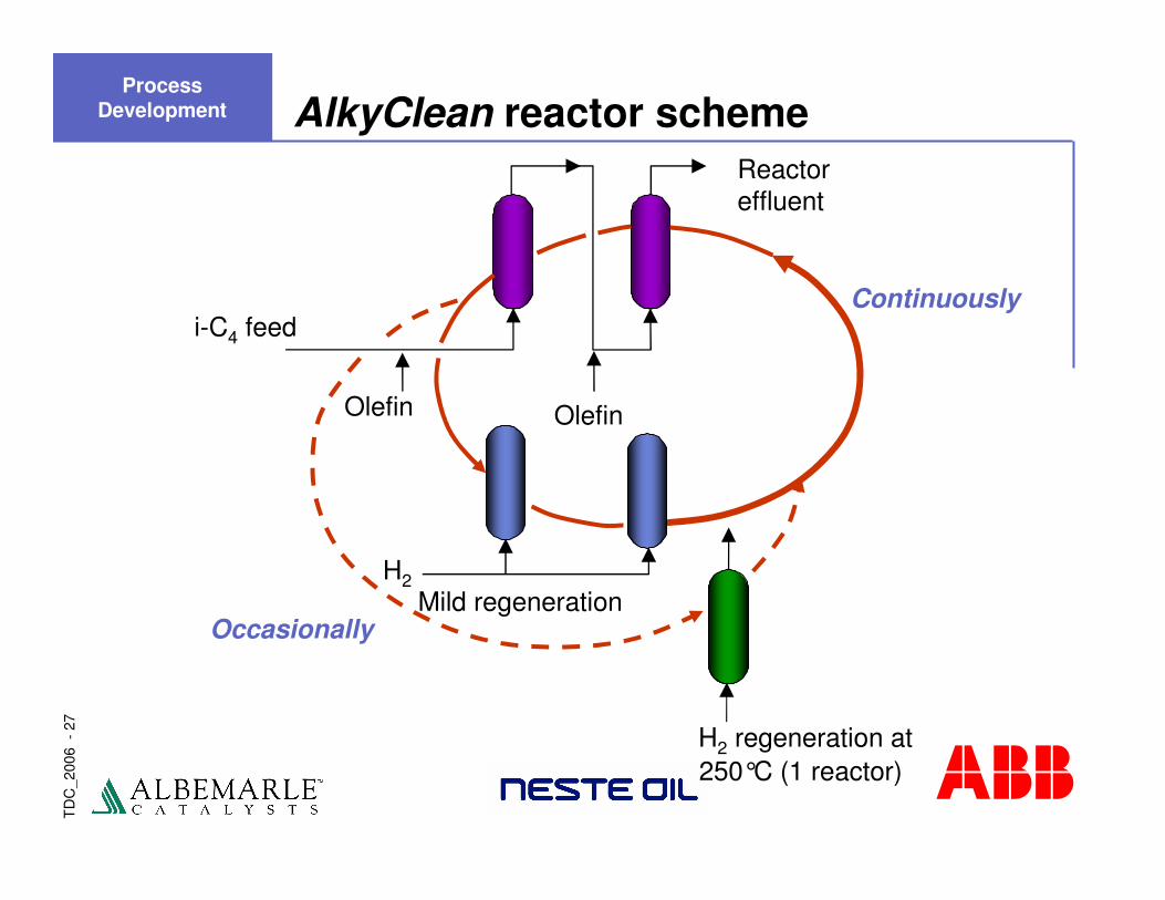
AlkyClean reactor scheme
i-C4 feed
Olefin
Reactoreffluent
Olefin
Occasionally
H2 regeneration at250°C (1 reactor)
Continuously
H2Mild regeneration
Process Development
TD
C_2
006
-28
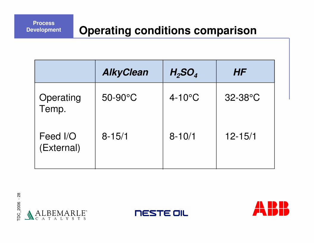
Operating conditions comparison
AlkyClean H2SO4 HF
Operating 50-90°C 4-10°C 32-38°CTemp.
Feed I/O 8-15/1 8-10/1 12-15/1(External)
Process Development
TD
C_2
006
-29
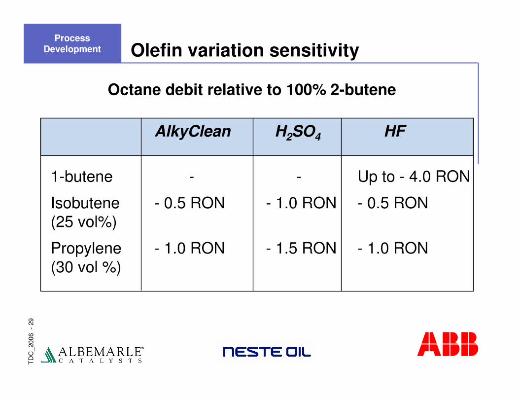
Olefin variation sensitivity
AlkyClean H2SO4 HF
1-butene - - Up to - 4.0 RON
Isobutene - 0.5 RON - 1.0 RON - 0.5 RON(25 vol%)
Propylene - 1.0 RON - 1.5 RON - 1.0 RON(30 vol %)
Octane debit relative to 100% 2-butene
Process Development
TD
C_2
006
-30
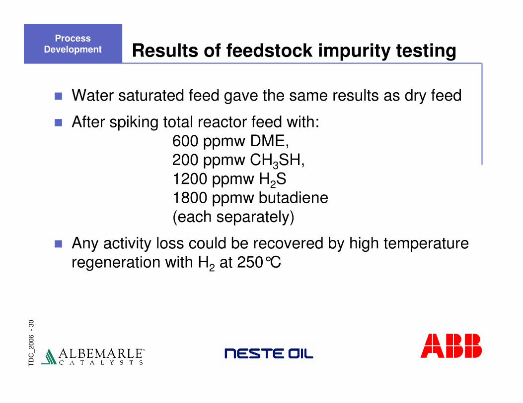
Results of feedstock impurity testing
� Water saturated feed gave the same results as dry feed
� After spiking total reactor feed with:600 ppmw DME,200 ppmw CH3SH,1200 ppmw H2S1800 ppmw butadiene(each separately)
� Any activity loss could be recovered by high temperature regeneration with H2 at 250°C
Process Development
TD
C_2
006
-31
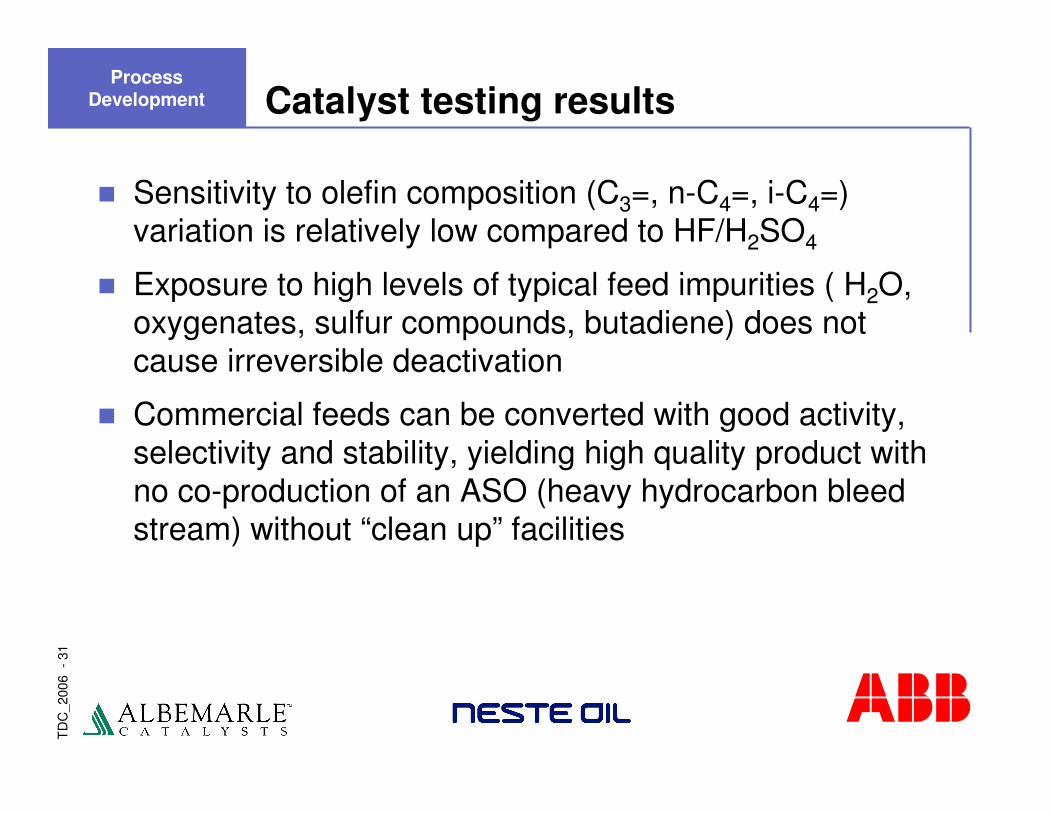
Catalyst testing results
� Sensitivity to olefin composition (C3=, n-C4=, i-C4=) variation is relatively low compared to HF/H2SO4
� Exposure to high levels of typical feed impurities ( H2O, oxygenates, sulfur compounds, butadiene) does not cause irreversible deactivation
� Commercial feeds can be converted with good activity, selectivity and stability, yielding high quality product with no co-production of an ASO (heavy hydrocarbon bleed stream) without “clean up” facilities
Process Development
TD
C_2
006
-32
AlkyClean���� solid acid alkylation
Presentation Outline
� Introduction
� Process Development
� Demonstration Unit
� Economic Benchmarking
� Summary
TD
C_2
006
-33
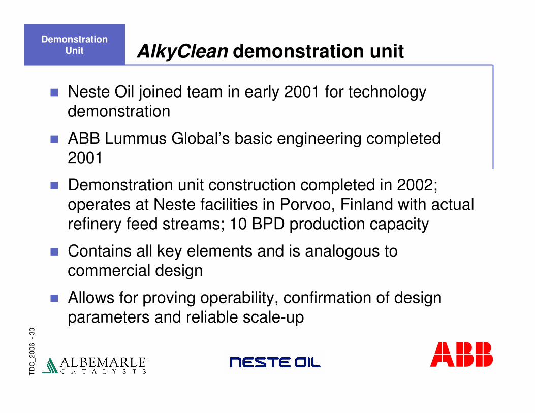
AlkyClean demonstration unit
� Neste Oil joined team in early 2001 for technology demonstration
� ABB Lummus Global’s basic engineering completed 2001
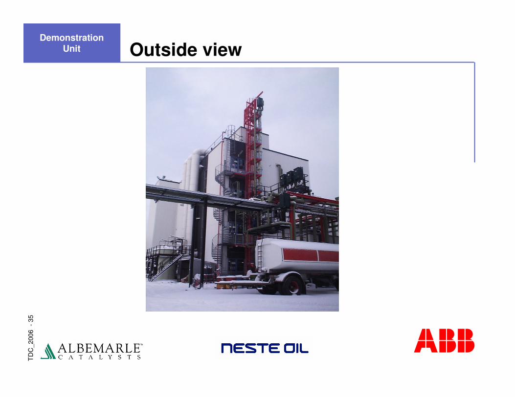
� Demonstration unit construction completed in 2002; operates at Neste facilities in Porvoo, Finland with actual refinery feed streams; 10 BPD production capacity
� Contains all key elements and is analogous to commercial design
� Allows for proving operability, confirmation of design parameters and reliable scale-up
Demonstration Unit
TD
C_2
006
-34
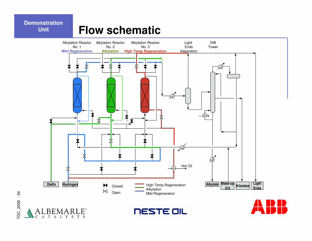
Flow schematic
Alkylate Make-upiC4 N-butane Light
EndsHydrogenOlefin
Hot Oil
High Temp RegenerationAlkylationMild Regeneration
Closed
Open
DIBTower
Light Ends
Separation
Alkylation ReactorNo. 3
High Temp Regeneration
Alkylation ReactorNo. 2
Alkylation
Alkylation ReactorNo. 1
Mild Regeneration
Demonstration Unit
TD
C_2
006
-35
Outside viewDemonstration
Unit
TD
C_2
006
-36
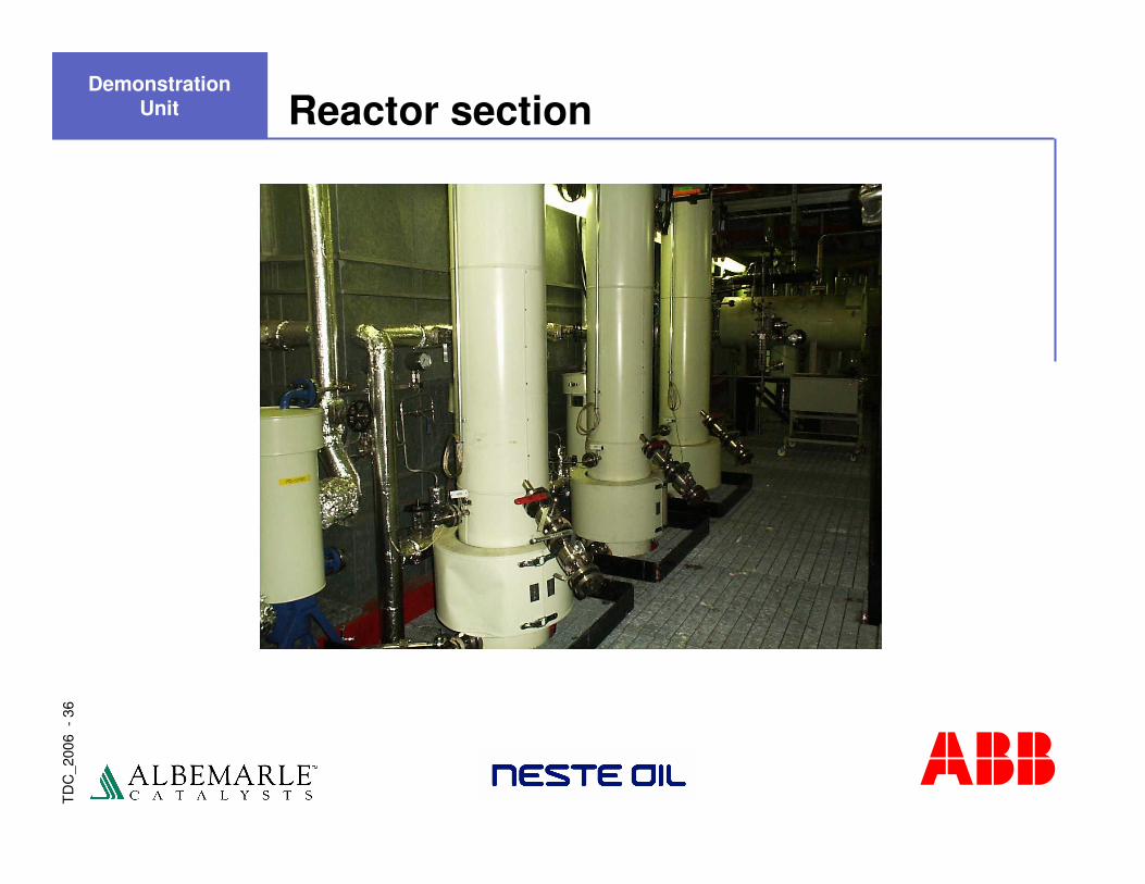
Reactor sectionDemonstration
Unit
TD
C_2
006
-37
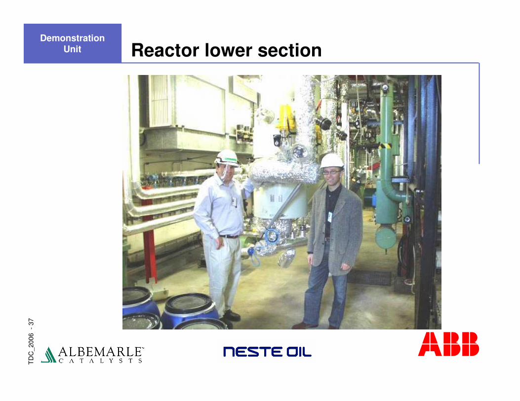
Reactor lower sectionDemonstration
Unit
TD
C_2
006
-38
AlkyClean demonstration unit
� Demonstration unit construction completed in 2002; operates at Neste’s facilities in Porvoo, Finland with actual refinery feed streams
� Contains all key elements and is analogous to commercial design
� Allowed for proving operability, confirmation of design parameters and reliable scale-up
Demonstration Unit

TD
C_2
006
-39
Operation summary
� Unit reliably operated for over two years utilizing refinery slipstreams, both C4 and C3/C4 mixed olefins
� Alkylate quality comparable to Porvoo HF unit
� Key technology aspects proven� Operated continuously with multiple high temperature regenerations
� Catalyst activity recovered consistently
� Performance data obtained over a wide range of conditions� Support correlations/modeling effort and economic benchmarking
� Some surprises, leading to insights and opportunities for catalyst/process optimization
� Absolutely no fouling, plugging, corrosion, erosion or degradation to the plant over the years of operation
Demonstration Unit
TD
C_2
006
-40
Recent operations
� In April 2004 second generation of catalyst tested:� Successful bench scale catalyst / processing optimization effort� As with the first generation, commercial trial manufacture of the new
improved catalyst� Demo unit modifications incorporated operational improvements
� Demonstration operated successfully for another six months� Benefits of operational improvements confirmed� Improved catalyst activity and stability confirmed
� Established excellent correlation between this unit and the bench scale unit
� Demonstration unit available for client feedstock testing� Bench scale unit continues to operate for parametric optimization
Demonstration Unit
TD
C_2
006
-41
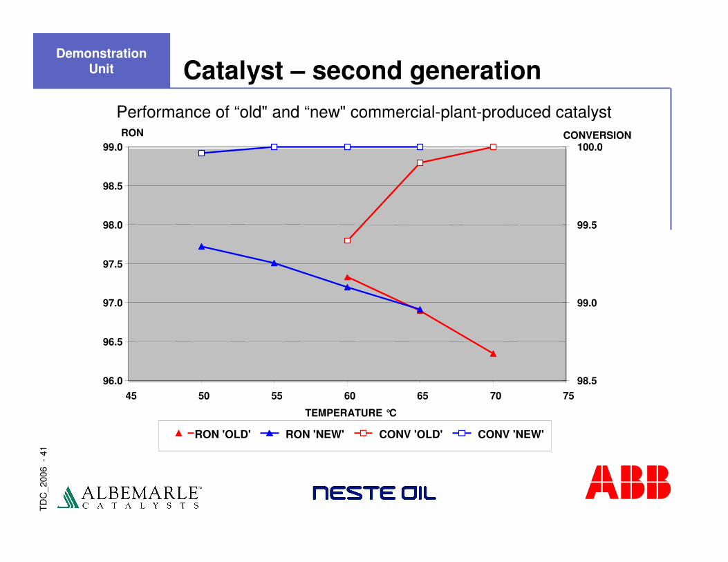
Performance of “old" and “new" commercial-plant-produced catalyst
96.0
96.5
97.0
97.5
98.0
98.5
99.0
45 50 55 60 65 70 75
TEMPERATURE °C
RON
98.5
99.0
99.5
100.0CONVERSION
RON 'OLD' RON 'NEW' CONV 'OLD' CONV 'NEW'
Catalyst – second generationDemonstration
Unit

TD
C_2
006
-42
Performance processing refinery C4 olefins
RON
Ole
fins
star
ted
Sta
rt
858687888990919293949596979899
100
0:00 12:00 24:00 36:00 48:00 60:00 72:00
Time (hh:mm)
0
Bed1 IN
Bed1 OUT
Bed2 OUT
Bed3 OUT
Bed4 OUT
Label
Demonstration Unit

TD
C_2
006
-43
Performance processing refinery C4 olefins
RVP
Ole
fins
star
ted
Sta
rt
0.000
1.000
2.000
3.000
4.000
5.000
6.000
0:00 12:00 24:00 36:00 48:00 60:00 72:00
Time (hh:mm)
PSI
0
Bed1 IN
Bed1 OUT
Bed2 OUT
Bed3 OUT
Bed4 OUT
Label
Demonstration Unit
TD
C_2
006
-44
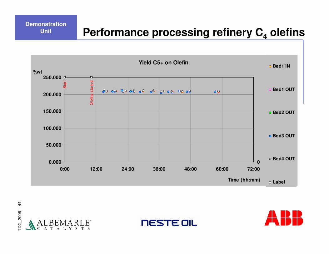
Performance processing refinery C4 olefins
Yield C5+ on Olefin
Ole
fins
star
ted
Sta
rt
0.000
50.000
100.000
150.000
200.000
250.000
0:00 12:00 24:00 36:00 48:00 60:00 72:00
Time (hh:mm)
%wt
0
Bed1 IN
Bed1 OUT
Bed2 OUT
Bed3 OUT
Bed4 OUT
Label
Demonstration Unit
TD
C_2
006
-45
AlkyClean���� solid acid alkylation
Presentation Outline
� Introduction
� Process Development
� Demonstration Unit
� Economic Benchmarking
� Summary
TD
C_2
006
-46
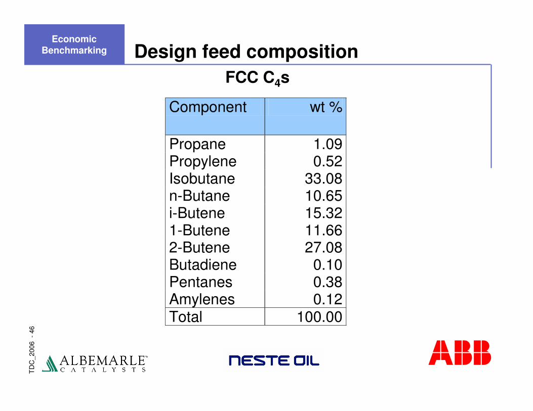
Design feed composition
Component wt %
Propane 1.09 Propylene 0.52 Isobutane 33.08 n-Butane 10.65 i-Butene 15.32 1-Butene 11.66 2-Butene 27.08 Butadiene 0.10 Pentanes 0.38 Amylenes 0.12 Total 100.00
FCC C4s
Economic Benchmarking
TD
C_2
006
-47
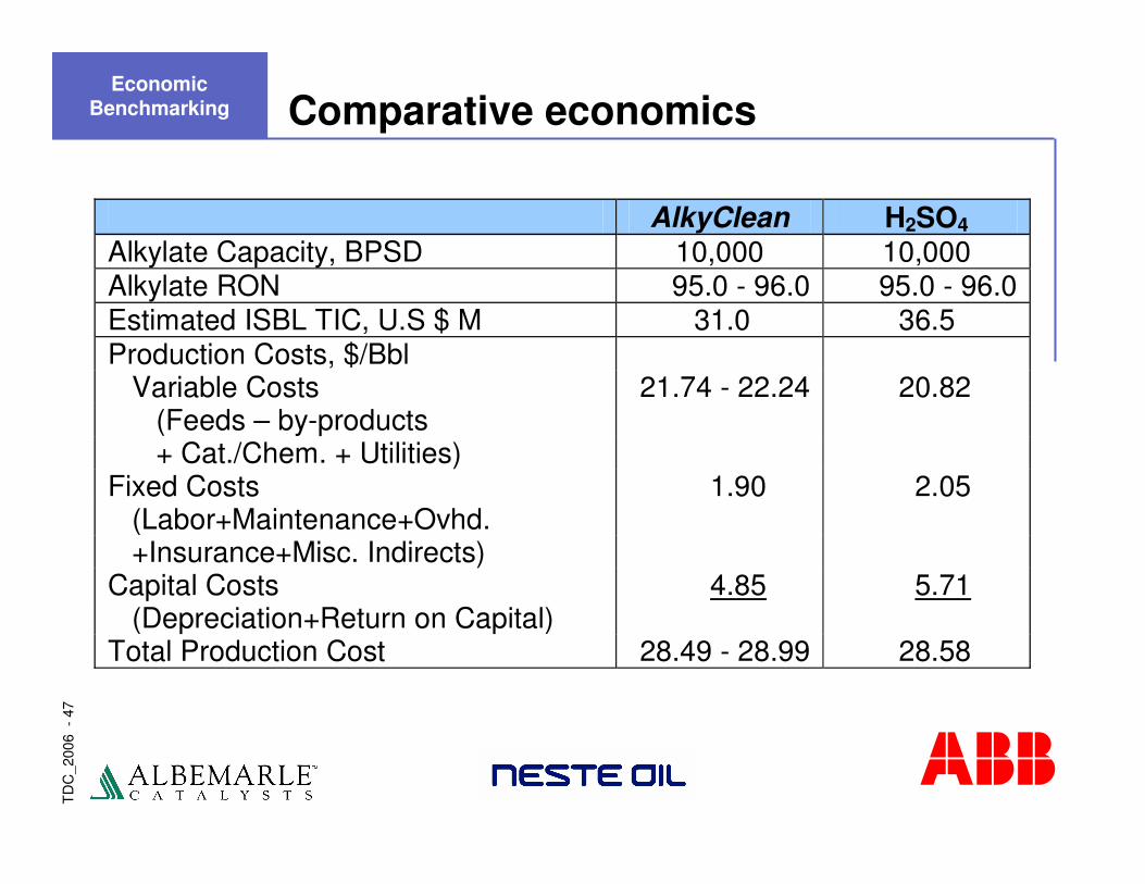
Comparative economics
AlkyClean H2SO4 Alkylate Capacity, BPSD 10,000 10,000 Alkylate RON 95.0 - 96.0 95.0 - 96.0 Estimated ISBL TIC, U.S $ M 31.0 36.5 Production Costs, $/Bbl Variable Costs 21.74 - 22.24 20.82 (Feeds – by-products + Cat./Chem. + Utilities) Fixed Costs 1.90 2.05 (Labor+Maintenance+Ovhd. +Insurance+Misc. Indirects) Capital Costs 4.85 5.71 (Depreciation+Return on Capital) Total Production Cost 28.49 - 28.99 28.58
Economic Benchmarking
TD
C_2
006
-48
AlkyClean���� solid acid alkylation
Presentation Outline
� Introduction
� Process Development
� Demonstration Unit
� Economic Benchmarking
� Summary
TD
C_2
006
-49
Benefits of the AlkyClean process� True solid acid catalyst eliminates the hazards
associated with liquid acids
� Low emissions / environmental impact
� No production of acid soluble oil (ASO)
� No product post treatment needed
� No refrigeration or alloy construction; common refinery equipment, non-corrosive/erosive
� Reduced maintenance and manpower
� Lower sensitivity towards olefin feed composition
� Robust with respect to key impurities
� Competitive economics with comparable alkylate quality
Summary
TD
C_2
006
-50
In conclusion
The AlkyClean process
� Offers significant environmental and operational benefits relative to existing liquid acid technologies at a competitive cost
� FYI… Wall Street Journal Europe Innovation Award 2002
Summary