development of a blended wing …using xflr5 code and martin heppler-45 (mh-45) airfoil is selected...
TRANSCRIPT
Symposium on Applied Aerodynamics and Design of Aerospace Vehicle (SAROD 2011) November 16-18, 2011, Bangalore, India
DEVELOPMENT OF A BLENDED WING CONFIGURATION MAV
D Thulasi Durai*, S R Viswamurthy#, Saniya Chaplod+, Govind Singh Dhami+, Smiti Maini+, Abhimanyu Sharma+, K Krishnamoorthy+
Centre of Societal Missions and Special Technologies CSIR-National Aerospace Laboratories, Bengaluru 560 017
ABSTRACT Micro Air vehicles "MAV" belong to a class of aircraft currently designated with a maximum size of 300mm and are
capable of operating at speeds of not less than 12 m/s. MAVs are expected to find applications in battlefield reconnaissance, visual surveillance, border patrol, etc. MAVs are typically characterized by a low aspect ratio wing operating at low Reynolds numbers (104~105). A camber plate MAV of 300mm wing span generates Cl of 0.7-0.8, comparatively Blended Wing MAV generates Cl of 1-1.3 this motivates the work to be carried out. This work contains the aerodynamic design, planform optimization, airframe modeling, production and development of a BLENDED WING MAV. Numbers of airfoils are analyzed using XFLR5 code and Martin Heppler-45 (MH-45) airfoil is selected due to its reflex at the trailing edge, very less camber of 1.17%, hence greater stability and also matches the requirements of the MAV. 2D CFD analysis is done using NAL RANS 3D code to validate the XFLR5 results of MH 45. Winglets were designed empirically using vertical tail volume coefficient (CVT). Polymer and Composite materials like- Acrylonitrile Butadiene Styrene (ABS), Kevlar & Rohacell, are used for fabrication of airframe and skin structure. An advanced technique like Rapid prototyping is used to produce the airframe and composite sandwich method is used for the skin material. Flight tests have been carried successfully and results are also discussed in this paper.
Key words: MAVs, Blended Wing, Winglets, XFLR5
NOMENCLATURE
AC Aerodynamic Centre CG Centre of Gravity Cd Drag coefficient Cl Lift coefficient AR Wing aspect ratio c Chord length b Wing span e Oswald efficiency factor ρ Air Density L Total Lift Sv Area of Vertical tail Lv Distance between the AC of Vertical tail and CG of wing Sw Area of Wing Re Reynolds Number M Mach number α Angle of Attack Cl/Cd Aerodynamic efficiency Cm Pitching moment Coefficient α Angle of Attack ___________________________________________ * Scientist, Centre of Societal Missions and Special Technologies # Scientist, Advanced Composites Division + Graduate Engineers, Centre of Societal Missions and Special Technologies National Aerospace Laboratories, Bangalore
1. INTRODUCTION
Micro Air Vehicles (MAVs) are a class of small light-weight aircrafts designed to operate in situations that are practically unsuitable for large aircrafts. Rapid advances in sensor technology, electronics and communication devices, in recent years, have opened a plethora of new applications for MAVs. MAVs are used for battlefield reconnaissance, visual surveillance, border patrol, or air sampling for civil purposes. MAVs are intended to operate in close proximity to a point of interest and should provide surveillance teams with critical information without being detected. The small size of MAVs suggests that in order to maximize the available lifting wing area, the chord and wingspan should be roughly equal to each other i.e. the aspect ratio should be almost equal to one. Wings of such low aspect ratios exhibit unique aerodynamic properties such as high stall-angles of attack and nonlinear lift versus angle of attack curves. Low Reynolds number of the order of 104~105 lead to lower lift to drag ratio and deterioration in performance.
There has been recent interest in micro air vehicles with a largest linear dimension not greater than 300 mm. The aircraft must be able to fly not less than 12 m/s, enduring greater than 30 min and climb to 100 meters altitude with a gross weight of not
D Thulasi Durai, S R Viswamurthy, Saniya Chaplod, Govind Singh Dhami, Smiti Maini, Abhimanyu Sharma and K Krishnamoorthy
more than 300gms. The MAV must be stable enough to serve as an airborne video platform.
Considering the above mentioned constraints and requirements, a blended wing design is chosen. Various conceptual planform designs are considered to serve for sufficient lift generation and systems’ accommodation. Blended Wing is finalized after preliminary analysis and a remote controlled model Blended Wing MAV is derived to meet the requirements. Research on alternative planforms is being continued with a drive towards improved aerodynamic performance and reduced gust sensitivity.
In this work, we present the development of a Blended wing configuration Micro Air Vehicle, starting from Aerofoil selection, planform selection, winglet sizing, airframe modeling and production, skin production, final assembly and flight tests.
2. LITERATURE SURVEY
Literature survey has revealed that tremendous amount of research is being carried out in the area of design and development of MAVs for various goals. Aerodynamic designs of MAVs, reported so far, have employed different kinds of efficient lift generation system viz., fixed wing, flapping wings, flexible wing and rotary wings or their combination [1]. The Blended Wing design is one of the recent areas of research within fixed wing MAVs because of its improved performance. Research has shown that blending the wing and fuselage and adding winglets provides a reduction in the extent of the wing-tip vortices and refocuses them away from the lifting surface [6, 10].
MAVs are characterized by Aspect Ratio close to unity [3]. For a given lift, a low AR wing has higher drag as compared to a high AR wing. Aspect Ratio also has a direct impact on stall angle. Since the wingtips in a low aspect ratio wing have a lower effective angle of attack, the wing will tend to stall at a higher angle than a high aspect ratio wing. With decrease in Aspect Ratio, the lift curve slope decreases and hence stalling is delayed [8].
The available literature on aerodynamic performance of airfoils at low Reynolds number [5] show poor performance and lower aerodynamic efficiency compared to higher Reynolds number [9]. This is mainly due to the flow separation at relatively low angle of attack. The laminar separation bubbles in this flow regime result in large parasite drag and low CLmax [7]. The most commonly used low Reynolds number airfoils are Selig, Eppler,
Wortmann, Althaus, Martin Heppler, Drela and Zimmerman [4].
Research suggests that the addition of winglets to an MAV can improve the lift characteristics and the lift-to- drag ratio of the vehicle significantly. However, one must be careful when choosing a winglet as ill-designed winglet can also reduce the performance of the MAV [6, 10].
The research group at University of Florida has been in the forefront of micro air vehicle development for more than a decade. Ifju et al have developed several successful fixed wing composite MAV airframes with maximum dimension ranging from 5 to 12 inches. The airframes were mostly made of unidirectional carbon fiber prepreg, Kevlar thread and tough mono film materials. They reported excellent flight characteristics and crash resistance. Their approach to airframe construction involved the integration of all materials and one tine vacuum bag curing. The most salient feature of their MAV airframe was the deliberate flexible qualities in gusty conditions. The flexibility of the wing structure was achieved by bonding a light weight, flexible, thin membrane material like latex rubber, polyester fabric etc, to cured carbon fiber skeleton. It has to be mentioned here though, that the mechanical properties of latex membranes are known to degrade significantly when exposed to light and heat [2].
3. AERODYNAMIC STUDIES
The aerodynamics of MAVs is greatly affected by the airfoil, operating chord based Reynolds number, planform shape, and wingtip devices like winglets. Airfoils in the low Reynolds number regime show poor performance and low aerodynamic efficiency due to boundary layer separation in laminar flow at a low angle of attack [6, 9]. A number of low Re airfoils were referred and system requirements and preliminary analysis filtered the choices. With low Aspect Ratios (close to unity), the lift curve slope decreases resulting in a delayed stall [8].
3.1 Airfoil Analysis and Selection
A number of airfoils were referred from various technical papers and UIUC (University of Illinois at Urbana-Champaign) database. The airfoils are studied in XFLR5 specifying the parameters; Mach no. 0.00, Reynolds no. 250,000,Angle of Attack -10º to 20º.
Performance studies on number of airfoils indicated that; GM78, J5012 and MH45 are the three
Development of a Blended Wing Configuration MAV
airfoils having better performance and meets the requirements of Blended Wing MAV.
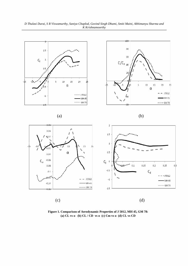
The comparison graph of aerodynamic performances of GM78, J5012 and MH45 is shown in figure 1 and the table below shows the values of the aerodynamic efficiency and coefficient of lift respectively.
Table 1. Performance comparison of the airfoils
GM 78 gives higher value of lift
coefficient around 1.2 at design angle of attack 7 degree than the other two airfoils sections. But figure 1(c) shows that GM 78 is less stable because of its irregular moment curve and also figure 1states that MH 45 is more stable than other two airfoils, at the same time it generates lift coefficient value around 1.0 which is enough to meet the requirements of the MAV at design angle of attack 7 degree.
3.2 2D CFD Analysis
To understand aerodynamic characteristics of an airfoil, two dimensional analysis is carried out using a multi-block structured flow solution algorithm – RANS3D (Reynolds Averaged Navier Stokes), developed at CTFD division, NAL, Bangalore [14, 15, 16]. This code is based on an implicit finite volume algorithm to solve the time averaged Navier Stokes equation for unsteady, incompressible turbulent flow with moving boundaries in an inertial frame of reference.
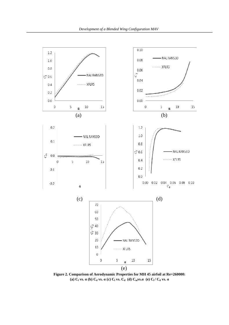
CFD flow simulation is carried out at different angles of attack using two blocks C-grid for MH 45 airfoil. The C-grid is generated using the CTFD in-house grid generation code [17], which is based on algebraic/ differential hybrid methodology. Performance curves and streamlines were plotted at operating chord based Reynolds number of 250000.The performance curves obtained using the RANS3D and XFLR5 code at Re=250000 are shown below (Figure 2).
The results obtained from both the codes are comparable. The difference observed may be due to the approximations made for the viscous corrections
in the XFLR5 code. The results of the RANS3D code may be more reliable as it is a high fidelity code. Due to the lack of measurement data, it is difficult to assess the performance of these codes.
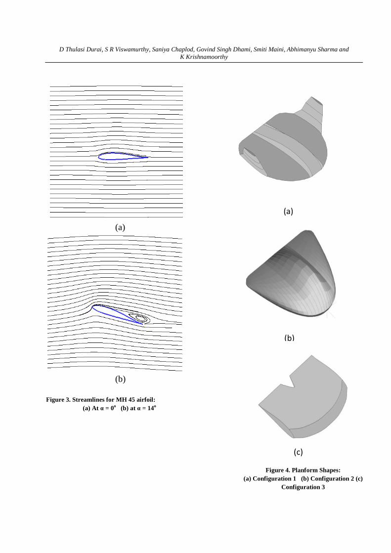
Figure 3 shows Streamlines for MH 45 airfoil at α = 0o and at α = 14o.The streamlines are plotted using Tecplot. A separation bubble is clearly observed at 14o.
3.3 Conceptual Planform Design
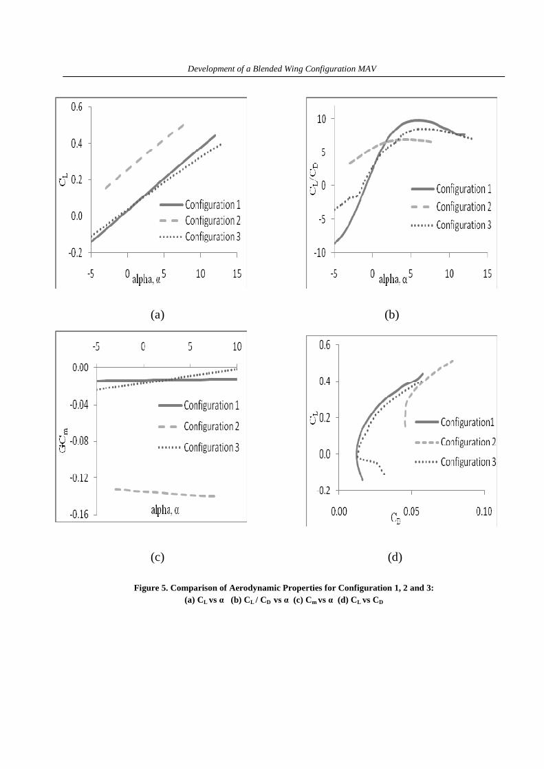
Three configurations of planform are shown in figure 4. Configuration 1 and 3 has inverse Zimmerman planform and Configuration 2 has a modified inverse Zimmerman planform.The above Configurations are designed for autopilot accommodation. Planform shapes are analyzed using XFLR5. Configuration 1 has in-built winglets and the other planforms are analyzed without winglets and after selection of the final planform, the analysis was done with winglets.
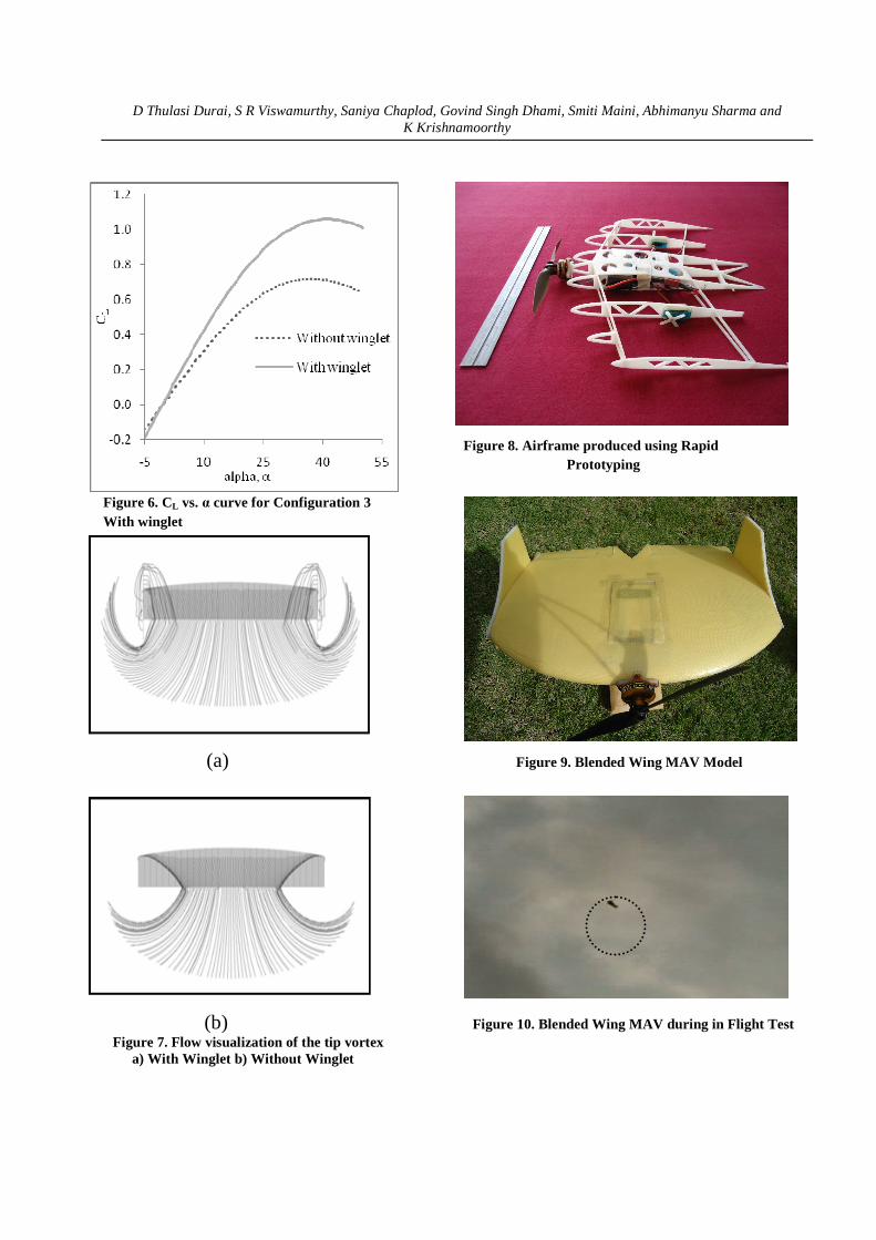
Comparisons of the performance analysis of all the three planforms are shown in figure 5. From figure 5(c) it is evident that configuration 2 has poor stability and hence it was discarded. Figure 5 also shows that the performance of Configuration 1 and 3 is almost comparable even with the latter having no winglets and the former with blended winglets. Also, the polar for configuration 3 with winglets (Figure 6) show better lift and aerodynamic efficiency than Configuration 1. So Configuration 3 was chosen for further analysis.
3.4 Stability and Winglet Studies
Directional stability is associated with angular motion about the z-axis (yawing motion). Vertical fin is the conventional mechanism for directional stability [1]. Winglets with 90o can help to reduce the induced drag and also serve as double symmetric fin for directional stability.
MAV aerodynamics is strongly affected by the wing tip vortices which extend over a significant amount of span. At the tips of any wing, the high pressure flow on the bottom surface of the wing and the low pressure on the top surface of the wing must be equal. These are generally not equal along the wingspan as this would lead to non-lifting wing. The existing pressure difference causes the flow from the bottom side to curl to the top creating a tip vortex and downwash at the wing tip. This downwash lowers the effective lift and leads to an increase in drag. This additional of drag is called induced drag or the drag due to lift. The drag increase is due to the tip vortex
Airfoil AOA C l/Cd Cl
GM78 70 70% 1.2
J5012 70 55% 0.7
MH45 70 70% 1.0
D Thulasi Durai, S R Viswamurthy, Saniya Chaplod, Govind Singh Dhami, Smiti Maini, Abhimanyu Sharma and K Krishnamoorthy
that causes energy loss in the flow. Induced drag depends only on the lift and the span of the wing and increases rapidly as the wingspan decreases. So increase in span would reduce induced drag but in the present case, due to dimensional constraints, addition of winglets is one of the most feasible options for reduction in induced drag.
The motivation for the use of winglets is to prevent or restrict the imminent downwash at the wingtips. Winglets can increase the performance by decreasing the induced drag. Although the addition of winglets does increase the surface area of the vehicle thus leading to higher frictional drag. It has also been observed that increasing the wingspan does lead to similar reduction in induced drag as addition of a winglet does. Addition of winglet moves the tip vortex up and away from the main wing .Thus causing less downwash at the wing and resulting in an increase in lift obtained with the wing [7, 11, and 13].
Figure 7 shows the flow visualization of the tip vortex with winglet and without winglet. Figure 6 Shows CL vs. α curve for BW configuration 3 with winglets.
Blending the wing and fuselage and adding winglets provides a reduction in the extent of the wing-tip vortices and refocuses them away from the lifting surface [7, 12]. A low aspect ratio wing at low Re features a tip vortex that can extend a distance up to 60% of the chord in the span wise direction. This large tip vortex is a source of drag and decreased lift. When winglet is added to the wing the size of tip vortex is decreased and moved off the lifting surface. Flow visualization & wind tunnel results show that adding winglets make a noticeable difference in CL,α=0, CLmax and CD for a given CL, but adding winglet increases the overall dimensions of MAV unless the winglets are attached at a 90º cant angle. A noticeable change in the lift and drag were not seen until the cant angle of the winglet was varied from 90º position. As the cant angle was decreased towards the horizontal, an expected increase in the lift was observed. This is due to the larger projected area of winglet onto the plane of the wing. With the addition of winglets, there is a significant increase in lift and aerodynamic efficiency of the planes.
3.5 Winglet sizing
The winglet sizing was done based on the Vertical tail Volume Coefficient (CVT). The higher this value is, the higher the degree of yaw stability [18],
V VVT
W
S LC
S b
×=×
Where, Distance between the AC of vertical tail and CG of wing (LV) = 43.39 mm
Area of wing (SW) = 72826.72 mm2
Span (b) = 300mm
Vertical tail volume coefficient (CVT) = 0.04
SV = Area of vertical tail=20141.061mm2
4. AIRFRAME & SKIN PRODUCTION, FINAL ASSEMBLY AND FLIGHT TEST
Airframe is the skeleton of MAV. Here total MAV weight is limited to less than 300 grams and weight allocation for airframe is just 60grams, hence the airframe designed should be light in weight, highly durable, capable of sustaining crash landings, and should be reusable. Taking the above said features into consideration, airframe is modeled using CATIA software. And it is inputted for fused deposition modeling a technique of Rapid Prototyping. Airframe produced using Rapid prototyping is shown in figure 8. The airframe Prototypes are produced by iterative process and optimized airframe weighs only 42 grams. Airframe is integrated with the propulsion system, battery and receiver. Skin is made up of Kevlar and rohacell sandwich which is less than 2 mm thickness. The final assembly of the Blended wing MAV is shown in figure 9. Model is hand launched and flight tests have been carried out in Remote Controlled (RC) mode. During flight trials it has been observed that model behaves as tail heavy due to the reflex camber airfoil as theory says and dead weight is added close to the nose of the MAV. Further model was stable during flight (Figure 10).
5. CONCLUSIONS
A light-weight Micro Air Vehicle has been developed through a systematic approach. To reduce interference drag and profile drag, blended wing configuration was selected. Modelling was done in 3D modeler and analysis was done in XFLR5.Many airfoils were analyzed in XFLR5 from which MH 45 was selected. The effect of winglets is captured which shows significant contribution to avoid tip vortex. Airframe will be developed using advanced fabrication techniques like rapid prototyping method and flight test will be conducted. In near future in-flight camber modification will be made to adopt the suitable flight conditions.
Development of a Blended Wing Configuration MAV
ACKNOWLEDGEMENT
The authors wish to acknowledge M B Subrahmanya, D S Kulkarni and B N Rajani (Computational and Theoretical Fluid Dynamics Division) for their support in validating XFLR 5 results with NAL RANS 3D code. And also thankful to Dr. G. N. Dayananda (Head, Centre for Societal Missions and Special Technolgies) for his support, Roshan Antony and Suraj (Propulsion Division) of NAL for conceptual and aerodynamic design of the micro air vehicle and also the Director, NAL for establishing the MAV fabrication facilities needed for this work.
REFERENCE
1. Micro Air Vehicle Design Papers, 6th International MAV Competition, Brigham Young Univ., Provo, UT, April 2002.
2. Dr. Tom Richardson, “Micro UAVs”, February 2007, University of Bristol Seminar.
3. Gabriel Torres and Thomas J. Mueller, “MAV Development: Design, Components, Fabrication and Flight Testing”, University of Notre Dame.
4. Carmichael, B.H., “Low Reynolds Number Airfoils Survey”, January 1982 NASA Contractor Report 165803.
5. “UIUC Airfoil Coordinates Database,” http://amber.aae.uiuc.edu
6. Charles O’Neill, “Low Reynolds Number Airfoils”, November 2001, MAE 5233
7. Dr. Helen L. Reed and Dr. William S. Saric, “Aerodynamic Studies of Micro Air Vehicles”, December 2001, Arizona State University.
8. Dr. Stephen J. Morris and Dr. Michael Holden, “Design of micro aerial vehicles and flight test validation”, MLB Company.
9. Anderson, John D., “Fundamentals of Aerodynamics”, 2nd Edition, McGraw-Hill, New York, 1991.
10. Anderson, John D., “Aircraft Performance and Design”, McGraw-Hill, New York, 1999.
11. Dr. Helen L. Reed and Dr. William S. Saric, “On the Effect of Winglets on the Performance of Micro-Aerial-Vehicles”, Arizona State University.
12. Prof. Hemendra Arya, “Miniature Aerial Vehicle Airframe Characterization”, IIT Bombay.
13. Engineering Sciences Data Unit, “Aerodynamic principles of Winglets”, Report No. 98013
14. S. Majumdar, Pressure based Navier Stokes solver for three dimensional flow in Hydrodynamics and low speed Aerodynamics application, Proc. 3rd Asian CFD Conference, Bangalore, 1.137-146, 1998.
15. S. Majumdar,W. Rodi, and J. Zhu, Three dimensional finite volume method for incompressible flows with complex boundaries, Journal of fluid engineering, ASME, :496-503, 1992.
16. S. Majumdar and B.N. Rajani, Numerical computation of flow around Aerostats using a pressure based Navier Stokes solver, Journal of Aeronautical society of India, 53(2): 117-127, 2001Nicholas K. Borer, “Design and Analysis of Low Reynolds Number Airfoils", December 2002.
17. A. Fathima, N.S. Baldava, S.Pal, and S. Majumdar, Grid generation for arbitrary 2D Configurations using a differential algebraic hybrid method, NAL PD CF 9461,1994.
D Thulasi Durai, S R Viswamurthy, Saniya Chaplod, Govind Singh Dhami, Smiti Maini, Abhimanyu Sharma and K Krishnamoorthy
(a) (b)
(c) (d)
Figure 1. Comparison of Aerodynamic Properties of J 5012, MH 45, GM 78: (a) CL vs α (b) CL / CD vs α (c) Cm vs α (d) CL vs CD
Development of a Blended Wing Configuration MAV
(a) (b)
(c) (d)
(e) Figure 2. Comparison of Aerodynamic Properties for MH 45 airfoil at Re=260000:
(a) Cl vs. α (b) Cd vs. α (c) Cl vs. Cd (d) Cmvs.α (e) Cl / Cd vs. α
D Thulasi Durai, S R Viswamurthy, Saniya Chaplod, Govind Singh Dhami, Smiti Maini, Abhimanyu Sharma and K Krishnamoorthy
(a)
(b)
Figure 3. Streamlines for MH 45 airfoil:
(a) At α = 0o (b) at α = 14o
(a)
(b)
(c)
Figure 4. Planform Shapes: (a) Configuration 1 (b) Configuration 2 (c)
Configuration 3
Development of a Blended Wing Configuration MAV
(a) (b)
(c) (d)
Figure 5. Comparison of Aerodynamic Properties for Configuration 1, 2 and 3: (a) CL vs α (b) CL / CD vs α (c) Cm vs α (d) CL vs CD
D Thulasi Durai, S R Viswamurthy, Saniya Chaplod, Govind Singh Dhami, Smiti Maini, Abhimanyu Sharma and K Krishnamoorthy
Figure 8. Airframe produced using Rapid Prototyping
Figure 6. CL vs. α curve for Configuration 3 With winglet
(a) Figure 9. Blended Wing MAV Model
(b) Figure 10. Blended Wing MAV during in Flight Test Figure 7. Flow visualization of the tip vortex
a) With Winglet b) Without Winglet