development of a computer program for optimum design...
TRANSCRIPT

DEVELOPMENT OF A COMPUTER PROGRAM FOR OPTIMUM DESIGN OF DIVERSION WEIRS
A THESIS SUBMITTED TO THE GRADUATE SCHOOL OF NATURAL AND APPLIED SCIENCES
OF MIDDLE EAST TECHNICAL UNIVERSITY
BY
KAM�L HAKAN TURAN
IN PARTIAL FULFILLMENT OF THE REQUIREMENTS FOR
THE DEGREE OF MASTER OF SCIENCE IN
CIVIL ENGINEERING
SEPTEMBER 2004

Approval of the Graduate School of Natural and Applied Sciences
I certify that this thesis satisfies all the requirements as a thesis for the degree of Master of Science.
This is to certify that we have read this thesis and that in our opinion it is fully adequate, in scope and quality, as a thesis for the degree of Master of Science.
Examining Committee Members
Prof. Dr. Do�an Altınbilek (METU,CE)
Prof. Dr. A. Melih Yanmaz (METU,CE)
Prof. Dr. Uygur �endil (METU,CE)
Assoc. Prof. Dr. Nuri Merzi (METU,CE)
Engin Günindi, M.S.C.E. (DOLSAR A.�.)
Prof. Dr. A. Melih Yanmaz Supervisor
Prof. Dr. Erdal Çokça Head of Department
Prof. Dr. Canan Özgen Director

iii
I hereby declare that all information in this document has been obtained and presented in accordance with academic rules and ethical conduct. I also declare that, as required by these rules and conduct, I have fully cited and referenced all material and results that are not original to this work.
Name, Last name :
Signature :

iv
ABSTRACT
DEVELOPMENT OF A COMPUTER PROGRAM FOR OPTIMUM
DESIGN OF DIVERSION WEIRS
Turan, Kamil Hakan M.Sc., Department of Civil Engineering
Supervisor: Prof. Dr. A. Melih Yanmaz
September 2004, 313 pages
A diversion weir is a headwork facility built across a river to raise the water level and to
divert water for various purposes, such as irrigation, hydropower generation, etc.
Diversion weirs with sidewise intakes are widely used in plain rivers. They are composed
of many structural components which are designed for different purposes. In this thesis, a
Windows-based, visual, user friendly program named WINDWEIR was developed in
Visual Basic.NET programming language for the optimum design of a diversion weir with
sidewise intake. It determines the overall dimensions of each of the components of the
diversion weir and the total cost of the whole structure. It also performs stability analysis.
It is such a flexible computer program that a design engineer can assess various
dimensions of the structure from viewpoints of safety and economy by performing quick
successive test runs to achieve an optimum solution among various alternatives.
Key words: Diversion weir, Sidewise Intake, Computer Aided Design.

v
ÖZ
REGÜLATÖRLER�N OPT�MUM TASARIMINA YÖNEL�K B�R
B�LG�SAYAR PROGRAMI GEL��T�RME
Turan, Kamil Hakan Yüksek Lisans, �n�aat Mühendisli�i Bölümü
Tez Danı�manı : Prof. Dr. A. Melih Yanmaz
Eylül 2004, 313 sayfa
Regülatör, sulama, elektrik enerjisi üretimi, vb. amaçlarla akarsu seviyesini kabartarak
akarsudan istenen miktarda suyun alınmasını sa�layan, akarsu üzerine in�aa edilen bir
çevirme yapısıdır. Yandan alı�lı regülatörler ova akarsularında sıkça kullanılmaktadır.
Yandan alı�lı regülatörler, de�i�ik amaçlar için tasarlanan bir çok yapısal parçadan
meydana gelmektedir. Bu tezde, yandan alı�lı bir regülatörün optimum tasarımına yönelik,
Visual Basic.Net programlama dilinde yazılmı� WINDWEIR adlı, Windows i�letim
sistemi altında çalı�an, görsel, kullanımı kolay bir bilgisayar programı geli�tirilmi�tir.
Program, regülatörün her bir parçasının bütün boyutlarını ve tüm yapının toplam
maliyetini belirlemekte ve yapının denge analizini yapmaktadır. Bu bilgisayar programı
ayrıca, hızlı ardı�ık denemelerle bir tasarım mühendisinin de�i�ik seçenekler arasından
optimum çözüme ula�abilmesi için yapının çe�itli boyutlarını güvenlik ve ekonomi
açılarından de�erlendirmesine olanak sa�layacak esnekliktedir.
Key words: Regülatör, Yandan Alı�lı Priz, Bilgisayar Destekli Tasarım.

vi
ACKNOWLEDGEMENTS
The author wishes to express his deepest gratitude to his supervisor, Prof. Dr. A. Melih
Yanmaz for his guidance, advice, criticism and insight throughout the study. The author
also would like to express his special appreciation to Prof. A. Melih Yanmaz for his great
patience and tolerance over the delays in the study.
The author would like to thank his father, O�uz Turan for his suggestions and comments.
The remaining family members are also gratefully acknowledged for their motivations and
continuous supports.

vii
TABLE OF CONTENTS
PLAGIARISM.…………………………………………………………..………………..iii
ABSTRACT.………………………………………………………………………………iv
ÖZ.…………………………………………………………………………………………v
ACKNOWLEDGEMENTS.………………………………………………………………vi
TABLE OF CONTENTS.………………………………………………………………...vii
LIST OF TABLES.………………………………………………………………...............x
LIST OF FIGURES.……………………………………………………………………….xi
LIST OF SYMBOLS.……………………………………………………………………xiii
CHAPTER
1. INTRODUCTION…………………………………………………………………1
2. DIVERSION WEIRS……………………………………………………………...3
2.1 Definition of Diversion Weirs…………………………………………...3
2.2 Classification of Diversion Weirs………………………………………..4
2.2.1 Classification According to Magnitude of Flood
Discharge………………………………………………...4
2.2.2 Classification According to Structural Design…….…….4
2.2.3 Classification According to Orientation of Intake……...5
2.3 Determination of the Location and Type of a Diversion Weir…………..9
2.4 Structural Components of Diversion Weirs with Sidewise Intakes……11
2.4.1 Spillway………………………………………………...13
2.4.2 Energy Dissipating Basin (Stilling Basin)……………..13
2.4.3 Sluiceway………………………………………………14
2.4.4 Guiding Wall…………………………………………...14
2.4.5 Sidewalls……………………………………………….15
2.4.6 Upstream Blanket………………………………………16
2.4.7 Riprap Section…………………………………….........16
2.4.8 Fish passage…………………………………………….16
2.4.9 Raft passage…………………………………………….17
2.4.10 Intake…………………………………………………...17
2.4.11 Some Appurtenant Structures…………………………..20

viii
3. HYDRAULIC DESIGN OF DIVERSION WEIRS……………………………..21
3.1 Hydraulic Design of Diversion Weirs with Sidewise (lateral) Intakes….21
3.1.1 Water Surface Profile Computations…………………...22
3.1.2 Design of Structural Elements………………………….22
3.1.2.1 Design of Intake…………………………...23
3.1.2.2 Determination of Spillway and Sluiceway
Discharges…………………………………36
3.1.2.3 Design of Energy Dissipators……………..39
3.1.2.4 Design of Upstream Levees……………….41
3.1.2.5 Design of Diversion Facility……………....42
3.1.3 Design of Some Appurtenant Facilities………………..46
3.1.3.1 Riprap Design……………………………..46
3.1.3.2 Design of Flushing Pipe…………………...47
3.1.4 Seepage Analysis……………………………………….49
3.1.5 Stability Analysis………………………………………52
3.1.6 Design of the Sidewalls………………………………...53
4. DEVELOPMENT OF THE COMPUTER PROGRAM…………………………54
4.1 The scope of the Computer Program……………………………………54
4.2 Programming Language…………………………………………………54
4.3 Framework of the Program……………………………………………...57
4.3.1 Main Program ………………………………………….58
4.3.1.1 Water Surface Profile Computations……...59
4.3.1.2 Program Module for the Design of Intake...59
4.3.1.3 Program Module for the Determination of
Spillway and Sluiceway Discharges………63
4.3.1.4 Program Module for the Design of Energy
Dissipator………………………………….67
4.3.1.5 Program Module for the Determination of
Crest Elevation of Upstream Levees………70
4.3.1.6 Program Module for the Design of the
Diversion Facility………………………….70
4.3.1.7 Program Module for the Riprap Design…...73
4.3.1.8 Program Module for the Design of Flushing
Pipe..………………………………………73

ix
4.3.1.9 Program Module for the Seepage
Analysis……………………………………76
4.3.1.10 Program Module for the Stability
Analysis……………………………………77
4.3.1.10.1 Stability against Uplift…...78
4.3.1.10.2 Stability against Shear and
Sliding……………………80
4.3.1.10.3 Stability against
overturning……………….84
4.3.1.10.4 Stability of the Sidewalls
(Design of the
Sidewalls)………………...86
4.3.1.11 Program Module for the Computation of the
Total Cost of the Diversion Weir………….88
4.3.2 Capabilities of the Program…………………………….89
4.3.3 Numerical Methods Utilized in the Program…………..88
4.3.4 Visual Interface of the Program………………………..93
5. APPLICATION………………………………………………………………….94
5.1 Definition of the Problem……………………………………………….94
5.2 Related Information………………………………………………….....94
5.3 Computations and Discussions…………………………………………95
6. CONCLUSIONS AND RECOMMENDATIONS……………………………..101
REFERENCES………………………………………………………………….……….103
APPENDICES
A. USER MANUAL FOR WINDWEIR………………………………………......106
A.1 Main Window of WINDWEIR……………………………………….106
A.2 Menu Items in WINDWEIR………………………………………….107
A.2.1 Menu Items Related to the File Management………..…107
A.2.2 Menu Items Related to the Input Data………………….109
A.2.3 Menu Items Related to the Computation……………….113
A.2.4 Menu Items Related to the Outputs…………………….114
A.2.5 Menu Items Related to the Help………………………..118
B. SOURCE CODE OF WINDWEIR.…...………………………………….........119

x
LIST OF TABLES
TABLES
3.1 Headloss coefficients due to transition types………………………………………...26
3.2 Fall velocities for quartz sand………………………………………………………..32
3.3 Values of C to be used in creep analysis……………………………………………..50
5.1 Input data obtained from the result of the water surface profile computations along
the river site…………………………………………………………………………...93

xi
LIST OF FIGURES
FIGURES
2.1 Sketch of a diversion weir with spillway……………………………………………...4
2.2 Sketch of a gated diversion weir………………………………………………………5
2.3 Sketch of a diversion weir with sidewise intake………………………………………6
2.4 Sketch of a diversion weir with frontal intake………………………………………...7
2.5 Sketch of a diversion weir with bottom intake………………………………………...8
2.6 Flow at bends………………………………………………………………………...10
2.7 Several orientations of intake………………………………………………………...11
2.8. Plan view of a typical diversion weir with a right sidewise intake…………………..12
2.9 Longitudinal profile of a typical spillway and stilling basin…………………………13
2.10 Longitudinal profile of a typical sluiceway and stilling basin……………………...14
2.11. Plan view and cross-section of sidewalls…………………………………………...16
2.12. Longitudinal profile of an intake……………………………………………………17
2.13 Types of transitions…………………………………………………………………19
3.1 Plan and profile of intake…………………………………………………………….24
3.2 Definition sketch for section-3 and section-8………………………………………..27
3.3 Definition sketch for settling basin design…………………………………………...31
3.4 Front view of the spillway and the sluiceways………………………………………37
3.5 Flow over the spillway and through the sluiceway. …………………………………37 3.6 Definition sketch for upstream levees………………………………………………..42 3.7 Definition sketch for diversion facility. ……………………………………………..44
3.8 Definition sketch for riprap design. ………………………………………………….46
3.9 Definition sketch for the design of flushing pipe. …………………………………...47
3.10 Definition sketch for Lane’s creep analysis.………………………………………..49
4.1 Flowchart illustrating the design of Intake…………………………………………...61
4.2 Flowchart for the determination of the spillway and sluiceway discharges……........63
4.3 Flowchart for the determination of the energy dissipators. ……………………….....68
4.4 Flowchart for the optimum design of diversion facility. …………………………….72
4.5 Definition sketch for the flushing pipe design algorithm. ………………………..….74
4.6 Flowchart for the design of flushing pipe...………………………………………….75

xii
4.7 Definition sketch for the foundation dimensions of the spillway and stilling basin…77
4.8 Definition sketch for the foundation dimensions of the intake and settling basin.......79
4.9 Definition sketch for the stability of spillway stilling basin against uplift………......81
4.10 Definition sketch for the stability of sluiceway stilling basin against uplift………..81
4.11 Definition sketch for the stability of settling basin against uplift. …………………81
4.12 Definition sketch for the representation of spillway body with a trapezoidal
section……………………………………………………………………………...82
4.13 Definition sketch for stability against shear and sliding……………………………82
4.14 Definition sketch for stability against overturning for full upstream no tailwater
case with respect to heel.……………………………………………………………85
4.15 Definition sketch for stability against overturning for empty upstream case with
respect to heel………………………………………………………………….......85
4.16 Definition sketch for stability against overturning for empty upstream case with
respect to toe…………………..…………………………………………………...85
4.17 Definition sketch for calculating the base pressures………………………………..86
4.18 Definition sketch for the design of the sidewalls…………………………………...87
4.19 Flowchart of the overall design of the diversion weir………………………………91
4.20 Flowchart representing the optimization of the bottom width at the beginning of
main irrigation canal……………………………………………………………….92
5.1 Cost versus main irrigation canal width for various thicknesses of stilling basin..….97
5.2 Cost versus main irrigation canal width for various length of upstream blanket……98
5.3 Cost versus main irrigation canal width for various heights of sheet piling…………99
A.1 Main window of WINDWEIR……………………………………………...……....106
A.2 Menu items related to the file management…………………………………….…..107
A.3 Window for selecting the project type……………………………………………...108
A.4 Menu items related to the input data………………………………………………..109
A.5 Input data window for intake profile………………………………………………..110
A.6 Input data window for spillway and sluiceway cross section………………………111
A.7 Window for the selection of the computation type…………………………………113
A.8 Window related to the computation processes….…………………………………..114
A.9 Menu items related to the outputs…………………………………………………..114
A.10 A typical output window displaying printout options……………………………..115
A.11 A typical output window for the selection of an available tabular output………...116
A.12 A typical output window for the selection of an available graphical output………117
A.13 A typical window displaying an available graphical output………………………117

xiii
LIST OF SYMBOLS
A : cross-sectional area of flow;
Abs : base area of the spillway;
Ag : gross area at the beginning of intake;
An : net area through the rack bars;
Ash: area of the shear plane;
B : bottom width at the beginning of main irrigation canal;
B1 : bottom width at the end of intake;
B3n : the net width of the channel at the entrance of the main canal;
Bs : width of the settling basin;
Bsn : net width at the entrance of the intake;
Bsw : width of the base slab of the sidewall;
b : bottom width of the diversion canal;
bop : optimum bottom width of the diversion canal;
C : relative permeability of soil;
C0 : design discharge coefficient for vertical faced ogee crest;
CT : total cost of the diversion facility;
Cc : minor loss due to curvature;
Cch : cost of diversion canal;
Ccore : unit cost of embankment core construction;
Cdc : cost of downstream cofferdam;
Ce : unit cost of excavation;
Cex : unit cost of expropriation;
Cinc : design discharge coefficient with sloping upstream face;
Cl : unit cost of canal lining;
Cma : design discharge coefficient due to apron effect;
Cme : design discharge coefficient for varying heads;
Cms : the design discharge coefficient due to submergence effect;
Com : overall modified discharge coefficient due to USBR method;
Cper : unit cost of embankment pervious fill construction;
Ct : headloss coefficient due to transition;
Cuc : cost of upstream cofferdam;

xiv
C' : the orifice discharge coefficient through the sluiceways;
D : median size of a particle;
Df : maximum diameter of objects entering the rackbars;
Dm : maximum possible size of material to be settled in the settling basin;
Dp : diameter of the flushing pipe;
Dr: diameter of the riprap;
d : depth of sluiceways;
dgwt : distance from the soil surface to the ground water table;
E3s : energy level at the riprap section at the downstream of the spillway;
E3sl : energy level at the riprap section at the downstream of the sluiceways;
El1 : Bed elevation where the pipe connects to river;
El2 : bed elevation at the end of the settling basin;
Eu : upstream energy level;
e : eccentricity;
FSo : factor of safety against overturning;
FSs : factor of safety against sliding;
FSss : factor of safety against shear and sliding;
FSu : factor of safety against uplift;
Fd : earthquake force;
Fh : hydrostatic force;
Fr : Froude number;
Fs : lateral active earth pressure;
Fu : uplift force;
Fuh : hydrostatic force acting on the subsurface portion of the spillway due to seepage;
Fw : upstream dynamic force due to earthquake;
f : freeboard;
fcf : friction coefficient between concrete and foundation;
fp : Darcy-Weisbach friction coefficient for the flushing pipe;
f*: elevation difference between the water surface elevation and the crest elevation of the
levee;
G : crest width of the cofferdam;
g : gravitational acceleration;
H : water depth above the crest of the spillway;
H0 : total head above the crest of the spillway;
Hd : horizontal inclination of outer layers of downstream cofferdam;

xv
He: existing total head over the spillway other than the design total head;
Hnet : net total head between the upstream of the spillway and the riprap section;
Hsp: height of sheet piling;
Hu : horizontal inclination of outer layers of upstream cofferdam;
Hx : the elevation at point x relative to a datum;
h : water depth at the upstream of the spillway;
ha : velocity head above the crest of the spillway;
hd: elevation difference between the upstream energy grade line and the downstream
(riprap section) water level;
hr_min : minimum riprap thickness to be laid;
I : moment of inertia of the spillway base;
K : an orifice coefficient;
K1 : bed elevation at the beginning of the main irrigation canal;
K100 : upstream water surface elevation for the flood discharge, Q100;
K50 : upstream water surface elevation for the flood discharge, Q50;
K25 : upstream water surface elevation for the flood discharge, Q25;
K10 : upstream water surface elevation for the flood discharge, Q10;
K5 : upstream water surface elevation for the flood discharge, Q5;
Ka :active earth pressure coefficient;
Kab : contraction coefficient due to abutments;
Kb : water surface elevation at section-b of diversion canal;
Kbs : foundation elevation of the stilling basin;
Kc : water surface elevation over the step at the end of the diversion canal;
Kd : water surface elevation at the riprap section;
Kd100 : water surface elevation at the riprap section for the flood discharge, Q100;
Kd50 : water surface elevation at the riprap section for the flood discharge, Q50;
Kd25 : water surface elevation at the riprap section for the flood discharge, Q25;
Kd10 : water surface elevation at the riprap section for the flood discharge, Q10;
Kd5 : water surface elevation at the riprap section for the flood discharge, Q5;
Kp : contraction coefficient due to piers;
Kr : bottom elevation at the riprap section;
Ks : crest elevation of the spillway;
Ksl : crest elevation of the sluicegates;
Kst : thalweg elevation at the entrance of the intake (spillway axis);
Ksw : crest elevation of the sidewalls;

xvi
Kta : minimum river bed elevation at section-a of the diversion canal;
Ktb : minimum river bed elevation at section-b of the diversion canal;
Ku : upstream water surface elevation;
Kus : bottom elevation of the stilling basin
Kv : Von Karman constant;
Kw: water surface elevation at a cross-section;
Kwi : water surface elevation in front of the intake;
kh : horizontal seismic earthquake coefficient;
ks : the equivalent sand roughness;
kv : vertical seismic earthquake coefficient;
L : crest length of the spillway;
Lc : length of curvature at the intake;
Lcr : creep length;
Ld : length of the riprap section;
Ldc : length of diversion canal;
Ld_min : minimum riprap length;
Le: width of sluiceway;
Lp : length of flushing pipe;
Ls : length of the settling basin;
Lub : length of upstream blanket;
Lx : the creep length up to point x;
LT : length of the valley at the crest elevation of the spillway;
Lt : length of transition;
M : the net moment about the centerline of the base of the spillway body;
nconc : Manning’s roughness coefficient for the concrete lined canal;
np : the number of bridge piers at the entrance of main irrigation canal;
npi : the number of bridge piers at the entrance of intake;
npipe : Manning’s roughness coefficient for the flushing pipe;
nps : the number of bridge piers above the spillway;
nriver : Manning’s roughness coefficient for the river;
nrow : number of the rows that the stones should be laid over;
nsl : number of sluiceways;
P : height of the spillway;
pa : lateral active earth pressure;
Q : discharge;

xvii
Q100 : flood discharge having a return period of 100 years;
Q50 : flood discharge having a return period of 50 years;
Q25 : flood discharge having a return period of 25 years;
Q10 : flood discharge having a return period of 10 years;
Q5 : flood discharge having a return period of 5 years;
Qi : irrigation discharge;
Qs : discharge over the spillway;
Qsl : discharge through the sluiceways;
R : hydraulic radius;
Rc : radius of curvature;
r : is the sediment removal ratio;
So: mean river bed slope;
Sos : bed slope of settling basin;
Sodc : mean slope of the diversion canal;
fsS : average friction slope;
tp : the thickness of one pier at the entrance of main irrigation canal;
tpi : the thickness of one pier at the entrance of the intake;
tps: thickness of one pier over the spillway;
tsb : thickness of stilling basin;
tsl : thickness of one pier between the sluiceways;
tslab : base slab thickness of the sidewall;
tsw : thickness of the sidewall;
u : average flow velocity at a cross-section;
u5max : maximum allowable flow velocity at the end of settling basin;
us : average flow velocity in the settling basin;
ux : the uplift pressure head;
u* : shear velocity;
u*c : critical shear velocity which initiates sediment motion at the bed;
Vu : vertical inclination of outer layers of downstream cofferdam;
Vd : vertical inclination of outer layers of upstream cofferdam;
Vsb1 : volume of USBR type 1 stilling basin;
Vsb2 : volume of USBR type 2 stilling basin;
Vsb3 : volume of USBR type 3 stilling basin;
Vsb4 : volume of USBR type 4 stilling basin;
W : dead loads;

xviii
Wf : fall velocity of a particle;
w : height of the downstream cofferdam;
wr : river width;
y : water depth at a cross-section;
y2,max : maximum value of the sequent depths of hydraulic jumps;
ycs : critical water depth at the toe of the spillway;
ycsl : critical water depth at the toe of the sluiceways;
yi : water depth in front of the entrance of the intake;
yo : normal water depth;
ys : depth of flow in the settling basin ;
z : height of upstream cofferdam;
zh : horizontal inclination of the trapezoidal canal;
� : step height at the end of diversion canal;
�s : end sill height of the spillway’s stilling basin;
�sd : downward step at the entrance of the settling basin;
�sl : end sill height of the sluiceways stilling basin;
�su : height of the upward sill at the end of the settling basin;
�u : upward sill at the beginning of the intake;
�E3s : headloss due to the hydraulic jump at the spillway downstream;
�E3sl : headloss due to the hydraulic jump at the sluiceways downstream;
�He : the minor loss above an upward sill;
�Hei : the minor loss above at the submerged curtain wall located at the entrance of the
intake;
�Hes : the minor loss above the downward sill, �sd ;
�Hg1 : minor loss due to gates;
�Hi : minor loss above the upward sill, �u ;
�Hs : frictional headloss through the settling basin;
�Ht : minor loss through the transition;
�Htr : minor loss at the thrashracks;
ΣH : total net horizontal force acting on the overall structure;
ΣLucre : the total creep length;
ΣLh : the total creep length in the horizontal direction.
ΣLv : the total creep length in the vertical direction;
ΣMo : total overturning moments;
ΣMr : total resisting moments;

xix
ΣV : total net vertical force acting on the overall structure;
Σ�x : the length of the river along which water rise occurs;
φ : uplift reduction coefficient;
� : angle from the upstream face of the spillway to the vertical direction;
� : dimensionless velocity;
�conc : specific weight of concrete;
�w : specific weight of the water;
: angle of repose of the soil;
: a parameter as a function of dimensionless velocity, β;
ρ : density of water;
�ac : allowable compressive strength of concrete;
�af : allowable compressive strength of foundation;
� : base pressure;
τo : shear stress through the pipe;
τoc : critical shear stress which initiates sediment motion at the bed;
τs : allowable shear stress in concrete.

1
CHAPTER 1
INTRODUCTION
Diversion weirs are one of the significant structures of water resources systems since their
design and construction require comprehensive and detailed work in terms of several civil
engineering aspects. Although the governing part of their design is related to hydraulic
engineering, other civil engineering divisions, such as structural engineering, geotechnical
engineering, and environmental engineering are also incorporated in the design process.
Another difficulty in the design of a diversion weir is due to the fact that it has many
structural components which are considered for different and special purposes. Each of
these components are interrelated to each other in terms of the data used in their design.
Therefore, this situation entails an organization of the data throughout the method of
design.
Hydraulic design of a diversion weir consists of many open-channel hydraulics concepts
to be implemented. However, this causes a wide range of hydraulic theory to be applied in
order to design all the structural components. In addition to this difficulty, diversion weir
design also depends on many number of variables which affect the design in different
ways resulting in various alternatives. This is the typical characteristic of a water
resources engineering problem that forces the designer to choose the best design through
iterative type of computational procedure. However, an iterative approach requires great
amount of computational work to be performed which is very difficult without the
utilization of computer programs. For those reasons, computer softwares play an
important role in the design of hydraulic structures, such as diversion weirs. Especially,
with the improvement in the computer sciences, better designs are done by using
sophisticated computer packages.
There are many computer programs that deal with different aspects of hydraulics and
other engineering disciplines. However, most of these programs are developed for general
purposes to attract greater number of customers due to economical considerations by the

2
developers of the packages. In this manner, a diversion weir design needs different
computer programs in order to perform the calculations corresponding to each of its
design problem. Although this is possible by using different packages in cooperation, by
this way, the efficiency of the designer decreases in terms of the time he spends for the
computations. This cumbersome process between one program to other also increases the
risk of making mistakes.
Among the different types, diversion weirs with sidewise intakes are widely used in
Turkey in plain rivers to divert water for irrigation purposes. By considering this fact, two
computer programs have been developed to fulfill the requirement of a computer aided
design for the diversion weirs with sidewise intakes ((Yanmaz and Cihangir, 1996),
(Yanmaz and Özaydın, 2000)). However, these programs were written for DOS operating
system which does not give a design engineer enough flexibility throughout the design of
a diversion weir. The aim of the current study is to develop a specialized software in
order to deal with the overall design of diversion weirs in context of hydraulic aspects by
extending the capabilities of these existing computer programs. More specifically, the
present study aimed to satisfy the needs by combining the hydraulic computations of the
components of the diversion weirs in a single computer program. A computer program
named WINDWEIR has been developed for this purpose. The program has a very flexible
visual interface working on the Windows operating system, which enhances the efficiency
of the user, resulting in better designs. In this study, it is intended to form a computer-
aided basis for an integrated design by assembling all the required aspects in a single
computer package.
This study is composed of the following chapters: Chapter 1 presents the general
information about the objective of the study. In Chapter 2, the detailed information about
the diversion weirs are introduced in parallel with the definitions of the corresponding
theories of hydraulics which establish a foundation for the design of the diversion weirs.
Hydraulic design of diversion weirs in a procedural way is explained in Chapter 3 which
constitutes the core of this study. In Chapter 4, the implementations of the algorithms
presented in Chapter 3 by WINDWEIR are clarified. An application of the program is
given in Chapter 5. Finally, the conclusions and the recommendations regarding this study
are presented in Chapter 6. Appendix A presents a user’s manual for WINDWEIR
whereas the source code of the program is given in Appendix B.

3
CHAPTER 2
DIVERSION WEIRS
2.1 Definition of Diversion Weirs
A diversion weir is a structure built across a river to raise water elevation up to a
specified level and to divert the water in a specified orientation for different purposes,
such as irrigation, hydropower generation, flood control, etc. There are some important
criteria that should always be satisfied in the design of diversion weirs irrespective of
type. These criteria are listed below (Yanmaz, 2001):
1. The desired amount of water should be diverted for most of the time.
2. The sediment grains in water should not be allowed to enter the water
intake. However, no matter how perfect the design is, some sediment will
always exist in the diverted water. Therefore, an ideal design should aim
at limiting the amount of entrainment of especially coarse sediment into
the intake.
3. Headlosses in the intake should be minimized in order to have a low
spillway.
4. Accumulated objects in front of the intake should be easily flushed
downstream.
5. The flow velocity should be controlled in order to protect the river bed
from the erosion and to protect the related structures from scouring.
6. Water level fluctuations in front of the intake should be decreased.
As it is seen from the above criteria, one of the most important aspects, that should be
considered in the design is the prevention of entrainment of sediment into intakes.
Especially in rivers carrying large sediment loads, this is an important problem that should
be solved.

4
2.2 Classification of Diversion Weirs
Diversion weirs can be classified according to various criteria (Yanmaz, 2001). These
classifications are presented in the following subsections.
2.2.1 Classification According to the Magnitude of Flood Discharge
In Turkey, diversion weirs are designed to withstand a flood discharge having a return
period of 100 years, Q100. Therefore, diversion weirs can be classified according to the
magnitude of Q100 as follows:
i. Small diversion weir (Q100 < 100 m3/s )
ii. Medium diversion weir (100 � Q100 � 500 m3/s )
iii. Large diversion weir (Q100 > 500 m3/s )
2.2.2 Classification According to Structural Design
i. Diversion weir with spillway : Raising of the water elevation is provided by
constructing a spillway across the river (see Figure 2.1). This study
concentrates basically on this type of diversion since most of the diversion
weirs in Turkey are designed for this type.
Figure 2.1. Sketch of a diversion weir with spillway.
Spillway (Body)
Raised water level a
a
Raised water level
Cross-section a-a initial soil profile (valley) Sluiceway

5
ii. Gated diversion weir : Raising of the water surface elevation is provided by
lowering the gates between the piers constructed across the river as shown in
Figure 2.2. This type of diversion weirs are capable of controlling the
upstream water level in the case of discharge fluctuations. Also by the use of
gates, flushing of the accumulated sediment in the upstream part of the
structure is easier. However, continuous operation of gates under high
dynamic impact may cause some operational problems, which can be seen as
a disadvantage of a gated diversion weir. Çulcu (2000) and Arslan (1996) can
be referred for a detailed survey on gated diversion weirs.
Figure 2.2. Sketch of a gated diversion weir.
iii. Mixed type of diversion weirs : This type of diversion weir is composed of
the combination of spillway and gated weir.
2.2.3 Classification According to Orientation of Intake
i. Diversion weir with sidewise (lateral) intake : This type of intake is the most
commonly used type among the others. This is generally suitable for plain
rivers where the sediment concentration in the vertical direction is close to
Bridge piers initial soil profile (valley)
Bridge slab
Gates
a
a Raised water level
Cross-section a-a
Water flow
Footing

6
uniform (see Figure 2.3). The present study is based on the computer assisted
hydraulic design of this type.
Figure 2.3. Sketch of a diversion weir with sidewise intake.
ii. Diversion weir with frontal intake : In this type of diversion weirs, the intake
structure is placed on top of the sluiceway to divert water with low sediment
concentration. A definition sketch shown in Figure 2.4 in which Q is the total
river flow and Qi is the diverted flow. With greater dimension of the
sluiceway better flow conditions can be facilitated. Normally, some sediment
is deposited in front of the sluiceway, but this sediment can easily be flushed
by water with the regular operation of sluice gates and by choosing a proper
bottom slope for the sluiceway, i.e. a recommended bottom slope is about
2.5% ((�endil, 1962), (Garbrecht, 1963), (Yanmaz, 2001)). Since proper
sediment handling can be established by frontal intakes, this type of structure
is best suited to steep sloped rivers where sediment handling is a more
important problem that should be solved.
Spillway and Energy dissipator
River flow
River flow
Diverted flow
Sidewise (lateral) Intake
a a
b
b
Cross-section a-a Cross-section b-b

7
Figure 2.4. Sketch of a diversion weir with frontal intake.
iii. Diversion weir with drop (bottom) intake : This type of intakes divert the
water from the crest of a spillway which is composed of screens as shown in
Figure 2.5. Water is taken into a drop structure while it is flowing over the
crest. This structure is best suited for very steep sloped mountainous rivers
where sediment deposition is a very important problem to handle. With a
sidewise intake, this problem is very difficult and uneconomic to overcome
since a large settling basin is required under such conditions. In addition,
Top view
Screens
Frontal intake
Screens
Sluiceway
Front view
Spillway (Body)
Diverted flow
Q
Qi Q - Qi
River flow
Sluicegate
a
a
Cross-section a-a
River bed
Screens
Qi
to intake (diverted flow)
to river
Sluicegate (sediment flushing)
initial soil profile (valley)
Spillway (Body)
Raised water level

8
some other structural components may be needed to handle the sediment
problem. Therefore, if the bed slope of the river is greater than 5%, a drop
type of intake is recommended. However, still some important precautions are
needed in order to overcome the sediment which falls into the drop. For a
more detailed information about diversion weirs with drop intake, Çeçen
(1962) is to be referred.
Figure 2.5. Sketch of a diversion weir with bottom intake.
Q
Diverted flow Qi
Q - Qi
Screens
Isometric view
Side view
Drop intake
canal
Q - Qi
Q
Qi
Screens
Bottom intake
water level
River flow

9
2.3 Determination of the Location and Type of a Diversion Weir
Purpose of the diversion weir, topography, soil conditions, orientation of the intake,
sediment transportation and river morphology plays important role in determination of the
location and the type of a diversion weir. For example, if a diversion weir is planned for
irrigation purposes, generally the location is determined according to the location and the
topography of the irrigation area. In a similar way, if a diversion weir is to be constructed
to form a by-pass channel to protect an important hydraulic structure from excessive flow,
then the river location where the structure is to be built is of importance.
Generally, in designing a diversion weir, the structure is desired to be built on a narrow
section of the river in order to minimize the size and the cost of the structure. However, if
upstream water level rises too much then big uplift forces due to excessive seepage
increases the size of the structure which leads to higher construction, maintenance, and
operation costs. Therefore, in general, for narrow valleys gated diversion weirs are
recommended, while in wide valleys diversion weirs with spillway should be desired.
Although above recommendations are important, in general, a final decision of the
diversion weir type should be obtained after making some economical and hydraulic
analyses iteratively.
In the design of diversion weirs, which are planned especially for irrigation purposes, one
of the most important issue that should be considered is sediment transportation. For
irrigation purposes, the main aim is to divert clean water from the river. Construction of
the structure effects the flow conditions of the river which causes changes in the river
morphology, such as erosion, deposition etc. By considering these effects, it can be
concluded that gated diversion weirs are more suitable in rivers carrying large amounts of
sediment loads, so that sediment can be transported by the proper operation of the gates.
Another important issue is the flow conditions at bends. In Figure 2.6 flow conditions in a
river bend are shown. Bends cause secondary flows which in turn cause sediment
deposition in the inner edge of the bend while erosion takes place in the outer edge due to
the effects of centrifugal force. The effect of secondary current is strongest at about two
times the river width downstream from the point where the river width downstream from
the point where the river axis intersects the outer bank. Therefore, it would be more

10
favorable to construct the water intake structure at this location (see Figure 2.6). This
advantage of the bends should also be considered in determination of the diversion weir
location. Furthermore, it may be a good decision to generate an artificial bend in the lack
of a natural bend in order to access this advantage of bends. For a more detailed study
regarding the hydraulics of flow at the bends, studies of Çulcu (2000) and Özbek (1989)
are also to be examined.
Figure 2.6. Flow at bends (Yanmaz, 2001).
Regarding the secondary flows at the bends, Habermaas (1955) has performed some
model studies under constant channel bed slope and resulted in the solution that the effect
of secondary flows can be diminished by the existence of an enlarged flow section in the
upstream of the intake. Figure 2.7 shows the several orientations of intake regarding the
sediment control facilities as the results of Habermaas’s studies.
In the light of the above discussions it can be stated that there exist many alternatives in
the design of diversion weirs. Most of the time, the best solution is found as a result of
iterative studies. Therefore, all the criteria on the determination of location and type of
diversion weirs are to be examined in a detailed manner and the most reasonable solution
is achieved by making joint hydraulic, structural, and economical analyses.
a
Rc
a SURFACE FLOW
SUBSURFACE FLOW
DEPOSITION
SCOUR
Plan
Cross-section a-a
INNER EDGE
wr
2wr
Diversion
OUTER EDGE

11
Figure 2.7. Several orientations of intake (Habermaas, 1955).
2.4 Structural Components of Diversion Weirs with Sidewise Intakes
The general layout of a diversion weir with a sidewise intake is shown in Figure 2.8.
Structural components are described in the following subsections.
a
b
c
d
% 100 G
% 0
% 100 G
E 300
480
K
E % 50 G
% 100 G
480
K
E % 95 G
% 100 G
% 100 G
600 % 100 G
% 0 G
% 0 G
% 100 G 600
% 100 G
e
G = SEDIMENT LOAD E = MAIN CANAL K= INTAKE CANAL
% 5 G
%50 G
K
E
E
K
K

12
Figu
re 2
.8. P
lan
view
of a
typi
cal d
iver
sion
wei
r with
a ri
ght s
idew
ise
inta
ke.

13
2.4.1 Spillway
Spillway is the main structural component of a diversion weir. The most important
function of the diversion weir is fulfilled by the spillway by raising the upstream water
level. In this way, water is diverted to the intake structure at a specified elevation.
Sometimes in addition to the spillway body, a bridge is constructed over the spillway for
service facilities. In Figure 2.9 longitudinal profile of a typical spillway can be seen.
2.4.2 Energy Dissipating Basin (Stilling Basin)
Stilling basin is the structure which is built at the toe of the spillway to prevent the
scouring of river bed. It is made of concrete blocks of compressive strength 250 kgf/cm2
placed in 5 m lengths approximately. The thickness of these blocks are determined
according to the safety of the slab against uplift. Longitudinal profile of a typical stilling
basin is also shown in Figure 2.9.
Figure 2.9. Longitudinal profile of a typical spillway and stilling basin.
Upstream sidewall
Sheet piling Riprap
Downstream sidewall
Drain Filter Stilling basin
Cutoff
upstream blanket
Spillway
Construction joints
Sill

14
2.4.3 Sluiceway
It is an important structural component of a diversion weir, which flushes the sediment
accumulated in front of the intake. Sluiceways have vertical lift gates called as sluicegates.
In front of the sluicegates, usually a submerged curtain is constructed. Deposited
sediment is flushed downstream to the river through the sluiceway. When sediment is
deposited up to a certain level, sluicegates are opened and deposited sediment is
discharged to the river by the help of the high flow velocities occurred through
sluicegates. Sluiceways are designed to have a bottom slope of about 1/20 to 1/50 in order
to facilitate flushing of the sediment to river (see Figure 2.10 for the longitudinal profile of
a typical sluiceway and stilling basin).
Figure 2.10. Longitudinal profile of a typical sluiceway and stilling basin.
2.4.4 Guiding Wall
In order to help sediment handling, a guiding wall is placed between the spillway and
sluiceway to deflect the sediment towards the sluiceway. This wall is called guiding wall.
Its orientation is an important issue and can be determined through hydraulic model
Riprap
Upstream sidewall
downstream sidewall
Stilling basin
Cutoff
upstream blanket
Sheet piling Construction joints
Sill
Submerged curtain
Bridge
Guiding wall
Gate

15
studies. According to the studies made by Özbek (1989), the following results were
obtained.
• Guiding wall length is an important factor in the design of diversion weirs
with sidewise intakes. It is seen that for the same amount of sediment
deposition, when small amount of water is discharged to the intake,
shorter guiding wall is needed, whereas longer guiding wall is necessary
when large amount of water is to be discharged to the intake. As a result it
is stated that; a guiding wall should be constructed in such a length that it
should cover the entrance of the water intake.
• Angle between the flow direction and the guiding wall should be about
150 ~ 200 .
• For a better sediment handling, flow through the sluiceway should not be
in submerged conditions.
• In order to achieve a well sediment flushing, higher and longer guiding
walls should be preferred. Although high and long guiding wall increases
minor headlosses, it gives better results from sediment handling point of
view.
• Sluicegates should be closed for a better deflection of sediment to the
front of the sluiceway.
2.4.5 Sidewalls
Sidewalls are the retaining walls which confine the river flow. Both gravity and cantilever
type reinforced concrete retaining walls can be used for sidewalls. Usually, cantilever type
is more preferable due to economical reasons. Plan view and cross-section of typical
sidewalls are shown below in Figure 2.11.

16
Figure 2.11. Plan view and cross-section of sidewalls (Yanmaz, 2001).
2.4.6 Upstream Blanket
They are formed of concrete blocks of 4*4 m2 in dimensions. An approximate thickness
of 30 cm is used as the thickness of these blocks. The main reason of the construction of
these blocks is to retard the seepage path. Also a sheet pile is driven at the end of the
upstream blanket to further increase the seepage path. By the construction of sheet pile
and upstream blanket, uplift forces decrease such that the desired level of safety against
uplift is achieved. In Figures 2.8, 2.9 and 2.10, upstream blanket and sheet pile are shown.
2.4.7 Riprap Section
At the end of the stilling basin, large ripraps are laid at least 75 cm thick and 10 m long in
order to protect the river bed.
2.4.8 Fish passage
A fish passage is the component which consists of successive pools to facilitate the
passage of fish from one side to other side of the structure. This structure has secondary
RIVER BOTTOM
RIVER FLOW
a a
Plan View Cross-section a-a
1:n
FILL
1:n FILL
SIDEWALLS

17
importance in the design of diversion weirs, because it is required to be built at sites where
fishing is of economic importance.
2.4.9 Raft passage
Similar to the fish passage, a raft passage is constructed for log transportation. It is
important at sites where log transportation is important as in the case of Scandinavian
countries.
2.4.10 Intake
Intake is an important structural component of a diversion weir because the water is taken
from the river through this component. The required discharge taken from the river is
transmitted to the main channel. The amount of discharge taken is controlled by the proper
opening of the gates installed at the entrance of the intake. There are some structural
components that compose the intake structure. Figure 2.12 shows the longitudinal profile
of a typical intake and its components. These components are described below.
Figure 2.12. Longitudinal profile of an intake.
Gate
Bridge Submerged curtain
Filter
upstream blanket
Sheet piling
Drain pipe
Settling basin
Sill Transition
Flushing gate

18
• Submerged Curtain : It is built within the flow section of water
perpendicular to the flow direction and placed in front of the gates in
order to prevent some floating objects, such as ice, logs, etc., to enter into
the intake. A minimum of 50~60 cm depth from the top of the intake is
recommended for the height of a submerged curtain.
• Screens : They are the racks placed in front of the gates to prevent the
entrainment of floating objects and coarse sediment into the intake.
• Settling basin : It is the enlarged compartment of intake serving for further
sediment handling purposes. The fine particles of sediment entering into
intake are captured at the settling basin. Length of the settling basin is the
main variable in capturing the sediment. Required length is calculated due
to the settlement of sediment grains up to a specified size. Although a
settling basin is usually a single large compartment with a rectangular
cross-section, some settling basins may be composed of successive small
compartments neighboring to each-other.
• Flushing pipe : The settled sediments deposited at the end of the settling
basin should also be discharged to the river. Therefore, a flushing pipe is
constructed at the end of settling basin which joins the river to flush the
deposited sediment to the river. Flushing pipe is designed to operate in
pressurized flow conditions. Therefore, when the required amount of
sediment is deposited at the settling basin, the gates in front of the main
canal is closed in order to achieve pressurized flow conditions in the
flushing pipe. Therefore, irrigation is stopped while the flushing pipe is in
operation. However, in the case of settling basin having some
compartments in series, some of the gates of the main canal are kept open
to continue irrigation. A flushing pipe is a circular conduit whose
diameter and slope are determined in order to achieve self-cleansing. A
minimum diameter of 60 cm is recommended for the conduit (Yanmaz,
2001).

19
• Transition : It is the structural part of the intake that connects the
rectangular settling basin to trapezoidal main irrigation canal. Bends are
used in order to change the flow direction. There are different types of
transitions, which can be seen in Figure 2.13. Straight Transition is widely
used because of ease of its construction. However, higher headlosses
occur through the straight transition. A Streamlined Transition is the best
one because of its geometry that minimizes the headlosses, but its
construction is difficult. In character, a Broken-Back type of transition is
between straight transition and streamlined transition such that the
headloss generated is smaller than a straight transition, but higher than a
streamlined transition and its construction is more difficult than the
straight transition but easier than the streamlined transition. The suitable
type is chosen by concerning both constructional difficulties and
hydraulics.
Figure 2.13. Types of transitions (Sungur, 1988).
Straight transition Broken-back transition
Streamlined transition

20
At the entrance of the intake, an upward sill with a minimum height of 60 cm above the
bottom of sluiceway is constructed such that the entrainment of the bed load into the
intake is avoided. However, water striking to the sill may generate secondary flows
causing some of the sediments to enter into the intake. Because of this possibility,
sluiceway should be operated with care concerning this problem.
2.4.11 Some Appurtenant Structures
The construction of a diversion weir is similar to the construction of a small dam in
various aspects. Therefore, in addition to the structural components of a diversion weir,
some appurtenant structures are needed. These appurtenant structures are described below.
• Levees : They prevent the flooding of the environment because of the
raised water at the upstream of the diversion weir.
• Cofferdams : A dry construction zone is provided by the construction of
cofferdams in the upstream and downstream part of the construction zone.
At the end of the construction period of the diversion weir, the cofferdams
are demolished and river starts to flow in its original bed by passing
through the diversion weir.
• Diversion Facility : River flow is diverted by a diversion canal usually
having a capacity of flow with return periods of 5 or 10 years.

21
CHAPTER 3
HYDRAULIC DESIGN OF DIVERSION WEIRS
3.1 Hydraulic Design of Diversion Weirs with Sidewise (lateral) Intakes
Design of a diversion weir is a complicated and tedious work, because all of the structural
components of the diversion weir are designed separately but in cooperation such that
design results of any component are inputs for the next component. Therefore,
computations regarding all of these components should be carried out in a systematical
procedure. The sequence of design computations are as follows:
• Water Surface Profile Computations
• Design of Structural Elements
o Intake
o Spillway
o Sluiceways
o Energy Dissipator
o Sidewalls
o Levees
o Diversion Facility
� Diversion Canal
� Cofferdams
• Design of some appurtenant facilities
o Riprap Design
o Flushing Canal
• Seepage Analysis
• Stability Analysis

22
3.1.1 Water Surface Profile Computations
After the planning stage in which the location of the diversion weir is selected, the first
step in the hydraulic design is water surface profile computations which are made along
the river reach where the spillway and corresponding energy dissipator are constructed.
This is a very important process, because the computations related to the structural
components of the diversion weir depend mostly on the water surface elevations. Since
the flow in a plain river is usually in sub-critical regime, the computational direction is
from the downstream toward the upstream. Therefore, the downstream rating curve needs
to be constructed in order to be used as a boundary condition for the hydraulic design.
For determining the downstream rating curve, firstly a flood frequency analysis for the
annual series of the maximum discharges should be made to calculate the flood discharge
values for various return periods. Downstream rating curve is plotted for the discharges
for the return periods of 5, 10, 25, 50, and 100 years. Therefore, the values of Q100, Q50,
Q25, Q10, and Q5 are needed for hydraulic analysis and design computations. Although a
diversion weir is designed for Q100, it should also serve with a good hydraulic performance
under smaller discharges, such as Q50, Q25, Q10, and Q5. Once these discharges are
obtained, the water surface profile computations can be carried out using HEC-RAS
(USACE, 1998) and BHSA (Yanmaz and Bulut, 2001) program packages, which will not
be covered in this thesis.
3.1.2 Design of Structural Elements
After water surface profile computations are made, the next step in the design of a
diversion weir is the determination of the dimensions of the structural components by
considering hydraulic criteria. Each sequential component is dimensioned by making
necessary hydraulic computations in a systematical order. In this section, hydraulic design
of each component is explained.

23
3.1.2.1 Design of Intake
Design of structural elements starts with the design of intake. The main aim in the design
of intake is to find the crest elevation of the overflow spillway. Starting from a known
water elevation at the beginning of the main irrigation canal, all the headlosses through the
intake are computed to find the corresponding water level at the entrance of the intake.
This is the minimum water elevation which must occur at the entrance of the intake in
order to provide the specified water level at the beginning of the irrigation canal for the
required irrigation discharge. This elevation is incremented by approximately 10 cm
accounting for water level fluctuations in front of the intake and further frictional losses
through the intake. The resulting elevation is taken as the crest elevation of the overflow
spillway. In this section, the headlosses through the intake are examined to explain the
design of intake starting from the irrigation canal to the entrance of the intake where crest
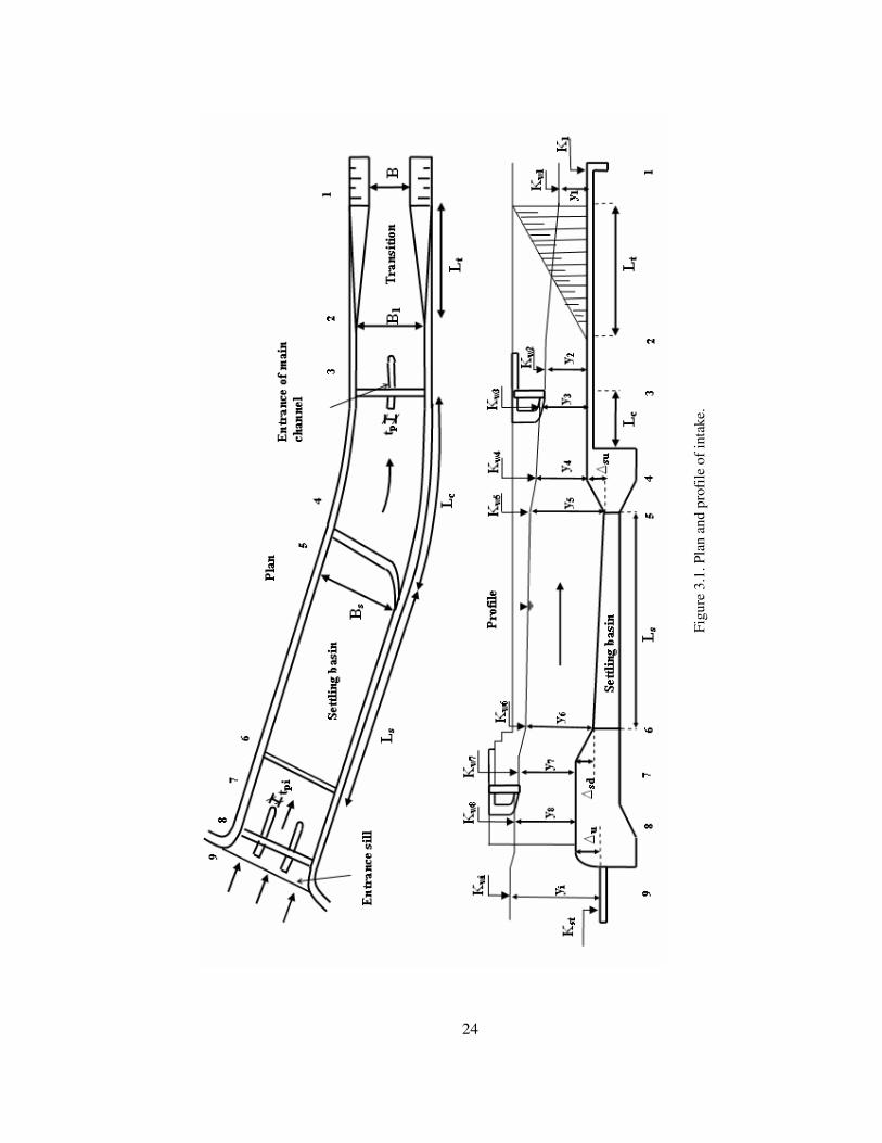
elevation of spillway is determined. Figure 3.1 shows the plan view and profile of intake
indicating the headlosses that should be considered. All the following computations are
explained with reference to Figure 3.1.
The required discharge taken to the intake is controlled by the proper operation of the
gates. Although Parshall flumes can be used for discharge measurement purposes, they are
not recommended for the reason that they cause considerable headloss in the intake.
Instead of using Parshall flumes, appropriate use of gates at the entrance can enable the
measurement of discharge.
Since the flow in the intake is in sub-critical regime, the boundary condition to be used in
headloss computations is the water level at the beginning of the main irrigation canal
which is section-1 in Figure 3.1. Therefore, calculations through the intake is performed
from the downstream (section-1) to the upstream (section-9) by using the energy equation.
Hydraulic computations are carried out to find water surface elevations at each section of
the intake by taking into account the related headlosses as follows:
• Cross-section-1: The bed elevation, K1, at the beginning of the main irrigation canal
is an input variable, which is obtained as a result of application of the layout of the
irrigation project on a physical map. The main irrigation canal has a trapezoidal
24
Figu
re 3
.1. P
lan
and
prof
ile o
f int
ake.

25
cross-section having side slopes of 1V:1.5H. These side slopes are specifically
recommended by taking into account both constructional difficulties and hydraulics
performance (USBR, 1952). In addition to these input data, with the known
irrigation discharge, Qi, channel bottom width, B, Manning’s roughness coefficient,
and the channel bed slope, S0, the normal depth, y1 is computed by using Manning’s
equation. Thus, the water surface elevation at that section (section-1), Kw1 is
determined as follows:
111 yKK w += (3.1)
Calculated water depth, y1, should be checked if it is greater than the critical depth of
that section, y1c such that y1 1.1y1c in order to be convinced that the flow is in a
stable sub-critical regime. The reason behind this check is to provide stable flow
conditions such that in close vicinity of critical depth, the flow is said to be unstable.
• Cross-section-2: The entrance of the intake and settling basin are usually designed for
rectangular cross-section, therefore, a transition connects the trapezoidal main
irrigation canal to the intake. Various types of transitions, which are shown in Figure
2.13, can be used for that purpose. The headloss generated due to the transition is
expressed as follows:
)2
(2
22
1
guu
CH tt
−=∆ (3.2)
where, �Ht : minor loss through the transition;
Ct : headloss coefficient due to transition;
u1 : average flow velocity at section-1;
u2 : average flow velocity at section-2;
g : gravitational acceleration.
Corresponding headloss coefficients due to different types of transitions can be
obtained in Table 3.1. The flow depth at section-2 can be determined by applying the
energy equation between section-1 and section-2 as follows:

26
gu
yguu
Cg
uy t 2
)2
(2
22
2
22
21
21
1 +=−++ (3.3)
The water depth at section-2 can be expressed as y2=Q/(B1u2) where B1 is the width
of the rectangular canal at section-2 and submitted in Equation (3.3). Minimum value
of 2B is proposed for the value of B1 (Yanmaz and Cihangir, 1996). Then, Equation
(3.3) can be solved for y2. Condition of u1 u2 should be satisfied for an inlet type of
transition. If this condition is not fulfilled, the value of B1 is incremented beyond 2B
value successively until the required condition is obtained. The water level at this
section, Kw2 is found by applying the energy equation by the insertion of calculated u2
value to Equation (3.4).
gu
KHg
uK wtw 22
22
2
21
1 +=∆++ (3.4)
Table 3.1. Headloss coefficients due to transition types (Chow, 1959).
Type of Transition Ct
Warped type 0.10
Cylinder-quadrant type 0.15
Simplified straight-line type 0.20
Straight-line type 0.30
Square-ended type 0.30+
The length of transition, Lt , can be determined from French (1987) :
21 65.1)(35.2 yzBBL ht +−= (3.5)
where zh=1.5 is the horizontal value of the side slopes of the main irrigation canal.
Since the transition length is usually not long enough to cause considerable frictional

27
loss, the headloss due to friction is usually eliminated in Equation (3.4). In case of a
long transition, it should also be considered in the calculations.
• Cross-section-3 : As seen in Figure 3.2, a gate is placed at section-3 to regulate the
flow and to prevent the entrainment of flow into the main irrigation canal during the
flushing of the sediment accumulated in the settling basin. The gates are installed
between a number of piers, thus, the flow velocity through the gate opening, u3 can be
determined by calculating the net flow area (see Figure 3.2).
123
3 *2 gn
i HgKyB
Qu ∆== (3.6)
where, B3n, is the net width of the channel at section-3 which can be expressed as:
ppn tnBB −= 13 (3.7)
where,
np : the number of piers;
tp : the thickness of one pier;
K : an orifice coefficient which can be taken approximately as 0.65 (Sungur,
1988);
�Hg1 : minor loss due to gates.
Figure 3.2. Definition sketch for section-3 and section-8.
Curtain wall
Plan view Cross-section a-a
tp
pier B1
flow
a a
gate
gate y3 y2

28
By making proper substitutions the water depth, y3 and water surface elevation, Kw3
can be determined by applying the energy equations as follows:
1
22
2
23
3 22 gHg
uy
gu
y ∆++=+ (3.8)
1
22
2
23
3 22 gww Hg
uK
gu
K ∆++=+ (3.9)
• Cross-section-4 : The width of the settling basin is larger than the width at the
entrance of the main irrigation canal. Therefore, a transition is provided between the
entrance of the main irrigation canal (section-3) and the end of the settling basin
(section-4) by a curvature having proper radius. The width of the rectangular settling
basin, Bs is greater than the width at the entrance of the main irrigation canal, B1 by a
reasonable amount, e.g. 1~ 2 m in order to obtain the desired amount of sediment
deposition in the settling basin as a result of the flow velocity. By considering the
local site conditions, the designer should select appropriate values for the length, Lc,
and the radius, r of the curvature. The minor loss generated by this curvature, �Hc, can
be determined as a certain percentage of the difference of the velocity heads at the
beginning and end of the curvature.
)2
(2
42
3
guu
CH cc
−=∆ (3.10)
where, u3 and u4 are flow velocities at sections 3 and 4, respectively. Minor loss
coefficient Cc can be taken as 0.2 (Sungur, 1988). As in previous sections, application
of energy equations between these sections gives the water depth, y3 and water surface
elevation, Kw3 at the end of the settling basin as follows:
gu
yHg
uy c 22
23
3
24
4 +=∆++ (3.11)

29
gu
KHg
uK wcw 22
23
3
24
4 +=∆++ (3.12)
where, u4 = Qi / (Bsy4).
• Cross-section-5 : At the end of the settling basin, an upward sill is required in order to
route the accumulated sediment in the settling basin to the flushing pipe. As well, the
entrainment of the deposited sediments to the irrigation canal is avoided by the
construction of this upward sill. An appropriate small velocity is required to facilitate
the suspended particles to settle down. Maximum permissible velocity of 0.3 m/s is a
reasonable value to be selected in the design (Yanmaz, 2001). By selecting the height
of the upward sill, �su in the range of 0.5 to 1.0 meter, the energy equation is applied
as:
esu Hg
uy
gu
y ∆+++∆=+22
24
4
25
5 (3.13)
where,
�He : the minor loss above the upward sill ;
u5 = Qi / (Bsy5).
Minor loss above an upward sill, �He , can be determined from the equation below
(Yanmaz, 2001):
)32
(88.2 42/3
eesi HyHBQ ∆+∆= (3.14)
Equation (3.13) and Equation (3.14) are solved for y5, and the water depth at section-
5 is obtained by satisfying the limitation; u5 � 0.3 m/s. If the limitations cannot be
satisfied by the selected value of �su, then firstly, �su is increased up to 1.0 m. If again
the requirement cannot be obtained, the width of the settling basin Bs is increased
until the required condition is satisfied. In the process which Bs is incremented, all the
computations are renewed from cross-section-4, since the new value of Bs must also

30
be used in the computation step of cross-section-4. When the limitation is satisfied,
the water surface elevation, Kw5 is determined from the following equation:
eww Hg
uK
gu
K ∆++=+22
24
4
25
5 (3.15)
• Cross-section-6 : This is the section where settling basin starts. In order to find the
water surface elevation at this section, the headloss through the settling basin should
be determined. For this purpose, the length of the settling basin needs to be
determined in order to calculate the frictional loss through the settling basin. The
length of settling basin, Ls, depends on the settlement of the sediments in the settling
basin which leads to the design of settling basin.
o Design of settling basin : The most important structural part of the intake is
settling basin in which sediments are settled to be flushed to the river by the
flushing pipe. Therefore, a relatively steep slope is needed in order to
facilitate the removal of the sediments from the bed until the end of the
settling basin. A bed slope of Sos = 0.01 is assigned for that reason (Sungur,
1988). Another important criterion to be considered in the design of the
settling basin is that although the storage section of the settling basin is filled
with sediment, the basin should still capture sediment. Thus, the minimum
length and depth of a settling basin should be selected to satisfy this
serviceability condition. Sümer (1977) proposed the following equation for
the length of a rectangular settling basin, Ls :
)1ln()(6
* rK
yuu
Lv
s
s −−=λ
(3.16)
where,
us : average flow velocity in the settling basin ;
y : depth of flow in the settling basin ;
u* : shear velocity in the settling basin ;
Kv : Von Karman constant which can be taken as 0.42 ;

31
: a parameter as a function of dimensionless velocity, β;
r : is the sediment removal ratio.
Shear velocity can be determined from equation :
sgRSu 0* = (3.17)
where, R is the hydraulic radius in the settling basin. Sümer (1977) proposed
the relation between and β as :
17.187.8 βλ = (3.18)
In equation (3.18), dimensionless velocity, β is expressed as:
*uK
W
v
f=β (3.19)
where, Wf is the fall velocity (see Figure 3.3).
Figure 3.3. Definition sketch for settling basin design.
Fall velocity for quartz sand in water at 200 can be obtained from the
following relations for different size of particles (Breuser and Raudkivi,
1991):
Wf
S0s
Ls
�su
�sd

32
for D < 0.15 mm ; 2663DW f = (3.20)
for D >1.5 mm ; DW f 5.134= (3.21)
where Wf is in mm/s and D is in mm.
Fall velocities for the particles having a diameter in the range of 0.15�D� 1.5
mm are given in Table 3.2.
Table 3.2. Fall velocities for quartz sand (Breusers and Raudkivi,1991).
D (mm) Wf (mm/s)
0.15 14.8
0.2 21
0.3 36
0.4 50
0.5 64
0.6 76.4
0.7 88.6
0.8 99
0.9 110
1.0 121
1.2 137.3
1.5 166
The median size of the particle D, is the input variable such that the particles
of larger sizes should be settled in the settling basin. Smaller size of particles
like silt, clay and colloids are allowed to be transferred by the canal system to
the fields where they have a fertilizing function. A reasonable value 0.5 mm
for the input value of D can be chosen for the design of the settling basin
(Yanmaz, 2001). Having calculated the fall velocity for the chosen median
size, Equations (3.17), (3.18) and (3.19) are used to find necessary values u*
and . For the flow depth in the settling basin, y, water depth at section-5, y5

33
can be used in order to have a conservative result. Average flow velocity, us
and hydraulic radius R in the settling basin are calculated using the value of
y5. Finally, the length of the settling basin, Ls, is determined from Equation
(3.16) by the substitution of the necessary variables.
The obtained value of Ls may be increased by 2.0 meters to be more conservative
(Yanmaz, 2001). If the energy equation is applied between sections 5 and 6, then the
water depth at the beginning of the settling basin, y6, can be calculated:
gu
ySLHg
uy ss 22
26
605
25
5 ++=∆++ (3.22)
where, �Hs is the frictional headloss through the settling basin which is equal to:
sfss LSH =∆ (3.23)
where, fsS is the average of the friction slopes at sections 5 and 6:
2
))
2(
(3/4
6
6
26
2
3/45
25
2
yBA
un
R
un
S sfs
+
+
= (3.24)
Hydraulic radius at section 5, R5, flow area at section-6, A6=Qi/u6 and the water depth
at section-6, y6=Qi/(Bsu6) are inserted into Equation (3.24) and friction slopes at
sections 5 and 6 are expressed by Manning’s equation. Then, the only unknown u6 is
determined from Equation (3.22) and inserted into Equation (3.25) in order to find
the water elevation at the beginning of the settling basin, Kw6:
gu
KHg
uK wsw 22
26
6
25
5 +=∆++ (3.25)

34
• Cross-section-7 : A downward step of �sd is placed at the entrance of the settling
basin. The minor loss above this sill is recommended to be taken as �Hes=0.02 m
(Sungur, 1988). Then, the flow depth of section-7 is determined from:
essd Hg
uy
gu
y ∆++=++∆22
26
6
27
7 (3.26)
where u7=Qi/(Bsy7) and the water elevation at section-7, Kw7 is obtained by the
following equation:
esww Hg
uK
gu
K ∆++=+22
26
6
27
7 (3.27)
• Cross-section-8 : This is the section where the entrance of the intake is placed. Similar
to section-3, gates are installed between the piers. The minor loss at the submerged
curtain wall located at the entrance of the intake can be computed in a similar way in
Equation (3.6):
eisn
i HgKyB
Qu ∆== 2
78 (3.28)
where, K=0.65 and Bsn is the net width which is equal to Bs-npi*tpi where, npi is the
number of piers and tpi is the thickness of one pier at this section. The flow depth, y8,
and the water surface elevation, Kw8 at the upstream of the gates are calculated by the
following equations:
eiHg
uy
gu
y ∆++=+22
27
7
28
8 (3.29)
eiww Hg
uK
gu
K ∆++=+22
27
7
28
8 (3.30)

35
• Cross-section-9 : This is the beginning of the intake which is located in front of the
gates by an upward sill of height �u that should be in the range of 0.5 to 1.0 meter.
The purpose of the upward sill is to prevent the entrainment of the bed material into
the intake. The minor loss above the upward sill, �Hi, is determined in the same way
as Equation (3.14) except the subscripts of the variables which indicates this section:
)32
(88.2 82/3
iisi HyHBQ ∆+∆= (3.31)
There are also trashracks which consists of racks of bars having 6 mm thickness at
the entrance of the intake to prevent the entrainment of floating objects to intake. The
minor loss at the thrashracks can be determined from (Baban, 1995):
gu
AA
AA
H n
g
n
g
ntr 2
))(45.0
45.1(2
2−−=∆ (3.32)
where, �Htr : minor loss at the thrashracks ;
An : net area through the rack bars ;
Ag : gross area at the beginning of intake;
un=Qi / An.
Finally, the water surface elevation at the entrance of the intake, Kwi, is determined
from :
gu
HHHg
uKK trieiwwi 22
28
27
7 −∆+∆+∆++= (3.33)
Once Kwi is obtained, the value of the upward sill, �u is computed by:
trstwiu HyKK ∆−−−=∆ 8 (3.34)
where, y8 : the water depth at section-8 ;
Kst : thalweg elevation at the entrance of the intake (spillway axis);
�Htr : minor loss at the thrashracks .

36
If the calculated value of �u is not in the range of 0.5 to 1.0 meter, then the value of
the downward step at section-7, �sd is changed and all the calculations regarding �sd
is renewed up to this point until the required condition is satisfied.
• Crest elevation of the overflow spillway : The elevation, Kwi obtained from Equation
(3.33) is actually the crest elevation of the overflow spillway. However, in order to
consider the water level fluctuations in front of the intake and further frictional losses
through the intake, Kwi is incremented by 10 cm and the crest elevation of the spillway
is obtained as:
10.0+= wis KK (3.35)
The height of the spillway, P is determined by subtracting the thalweg elevation, Kst
at the spillway axis from the crest elevation of the spillway, Ks.
sts KKP −= (3.36)
3.1.2.2 Determination of Spillway and Sluiceway Discharges
The river discharge is separated into two such that a large amount flows over the spillway
while the rest flows through the sluiceways. Therefore, each of the discharge should be
determined in order to design the energy dissipators at the toe of the spillway and
sluiceways. By the continuity equation of flow, the design discharge, Q100, is equal to the
summation of the discharge over the spillway, Qs and the discharge through the sluiceway,
Qsl:
sls QQQ +=100 (3.37)
By using Equation (3.37) as the boundary condition for the computation process, the
spillway and the sluiceways discharges are found by a trial and error procedure. This
procedure can be summarized with reference to Figures 3.4 and 3.5 as follows:

37
Figure 3.4. Front view of the spillway and the sluiceways.
Figure 3.5. Flow over the spillway and through the sluiceway.
Sluiceways
d
Le tsl
Spillway body
LT
L
K100
Ks
Ksl
Kst
Kd100
h
EGL
H0
�s
y1 y2
y3 Kr
�E E3s
Eu
K100
Kst
Flow over the spillway
H
ha Ks
Kst
h
d
EGL
�sl
y1
�E E3sl
y2
y3 Kr
Kd100
Eu
K100
Flow through the sluiceway
Ksl
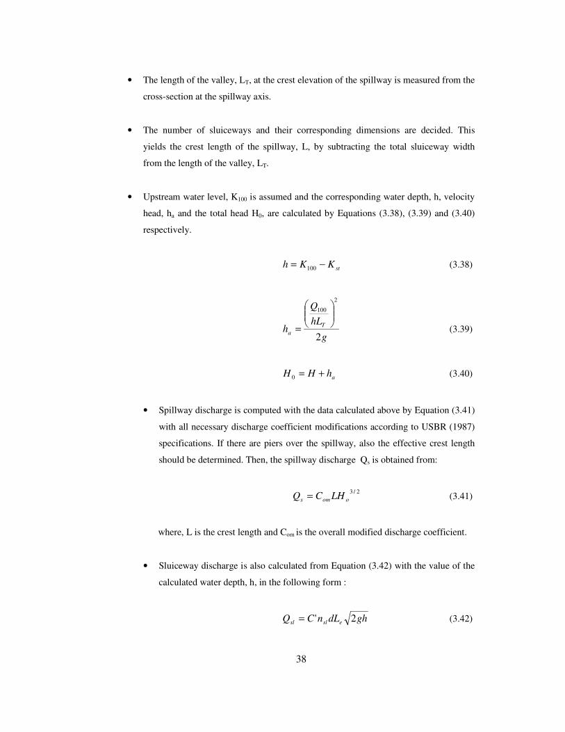
38
• The length of the valley, LT, at the crest elevation of the spillway is measured from the
cross-section at the spillway axis.
• The number of sluiceways and their corresponding dimensions are decided. This
yields the crest length of the spillway, L, by subtracting the total sluiceway width
from the length of the valley, LT.
• Upstream water level, K100 is assumed and the corresponding water depth, h, velocity
head, ha and the total head H0, are calculated by Equations (3.38), (3.39) and (3.40)
respectively.
stKKh −= 100 (3.38)
g
hLQ
h Ta 2
2
100���
����
�
= (3.39)
ahHH +=0 (3.40)
• Spillway discharge is computed with the data calculated above by Equation (3.41)
with all necessary discharge coefficient modifications according to USBR (1987)
specifications. If there are piers over the spillway, also the effective crest length
should be determined. Then, the spillway discharge Qs is obtained from:
2/3ooms LHCQ = (3.41)
where, L is the crest length and Com is the overall modified discharge coefficient.
• Sluiceway discharge is also calculated from Equation (3.42) with the value of the
calculated water depth, h, in the following form :
ghdLnCQ eslsl 2'= (3.42)

39
ghdLnCQ eslsl 2'= (3.42)
where,
C' : the orifice discharge coefficient that can be taken to be 0.65 as a
conservative value for the sake of simplicity,
nsl : number of sluiceways,
d : depth of sluiceways,
Le: width of sluiceway.
• Equation (3.37) is checked if it holds true with an allowable error. If Equation
(3.37) is not satisfied, then, a new value of K100 is assumed and all the
computations are repeated until Equation (3.37) is satisfied.
• For each flood discharge, these computations are performed and corresponding
spillway and sluiceway discharges are obtained.
3.1.2.3 Design of Energy Dissipators
One of the most important part in the design of the diversion weirs is the design of energy
dissipators. After the determination of the spillway and sluiceways discharges and the
upstream water levels as described in the previous section, the next step is to analyze the
flows at the toe of the spillway and sluiceways. Since the river flow is divided into two as
over the spillway and through the sluiceways, there exist different flow conditions at
these locations. Therefore, hydraulics of these locations are analyzed separately. This
may result different energy dissipators at the toe of the spillway and sluiceways. The
design procedure can be systemized with reference to Figures 3.4 and 3.5 as follows:
• The upstream energy elevation, Eu is computed by adding the value of ha
computed from Equation (3.39) to the upstream water level, K100.
au hKE += 100 (3.43)

40
g
LyQ
yE
s
s 2
2
333
���
����
�
+= (3.44)
g
ytnLnQ
yE slslesl
sl
sl 2
))1((
2
333
���
����
�
−++= (3.45)
where,
Qs : Spillway discharge,
Qsl : sluiceway discharge,
y3 : the water depth at the riprap section,
L : crest length of the spillway,
nsl : number of sluiceways,
Le : width of the sluiceway,
tsl : thickness of one pier.
• By ignoring the headloss at the face of the spillway and sluiceways, headloss due
to the jump is obtained both for spillway and sluiceway as below:
sus EEE 33 −=∆ (3.46)
slusl EEE 33 −=∆ (3.47)
• Critical water depths at the toe of the spillway, ycs and the sluiceways, ycsl are
calculated. From the ratios of �E/ycs and �E/ycsl , the conjugate depths of the jump
are found.
• According to the sequent depth and the tailwater depth, the energy dissipation
basin is selected (USBR, 1987). The required sill height at the downstream of the
basin is also calculated.

41
• According to the sequent depth and the tailwater depth, the energy dissipation
basin is selected (USBR, 1987). The required sill height at the downstream of the
basin is also calculated.
• These calculations are performed for each flood discharge. Therefore, number of
flood discharge times energy dissipation basins are designed for the toes of both
spillway and sluiceways. A final single basin is selected among these alternatives
by considering the worst hydraulic conditions for both spillway and sluiceway.
• If the final designed basins for the spillway and sluiceway are both of the USBR
type 2,3, or 4, then the following inequality is checked to be true or not:
50>∆−∆ sls cm (3.48)
where, �s is the end sill height of the spillway’s stilling basin, whereas, �s is of
the sluiceways’ stilling basin.
• If inequality (3.48) is satisfied, this means that separate stilling basins should be
constructed for spillway and sluiceway divided by a wall with a common length
which is determined as the maximum value among the alternatives. If inequality
(3.48) is not satisfied, then a common stilling basin should be provided for both of
them with the greater sill height among �s and �sl.
3.1.2.4 Design of Upstream Levees
Levees are constructed in order to protect the upstream environment from flooding due to
the rise of the water at the upstream of the diversion weir (see Figure 3.6). Therefore, the
backwater amount should be determined. This directs to a water surface profile
computation through the river at the upstream of the diversion weir. Computations are
made for design discharge, Q100 from downstream to upstream. The downstream boundary
condition is the water level over the spillway, K100 which is determined during the design
process of the spillway and sluiceway.

42
Figure 3.6. Definition sketch for upstream levees.
Water surface profile computations are carried out for a reasonable cross-section interval
until the uniform flow condition at the upstream is obtained.
3.1.2.5 Design of Diversion Facility
Diversion facility is designed to provide a dry construction zone during the construction
period of diversion weir. In order to provide a dry construction zone, cofferdams are
constructed at the upstream and downstream of the diversion weir and river flow is
diverted from its natural bed all the way through the construction zone by a diversion
canal . Since diversion canal will serve only during the construction period of the
diversion weir, it is usually designed to have a capacity of carrying flood discharges, Q5,
or Q10. In Figure 3.7, a sketch demonstrating the diversion facility is presented. Diversion
canal starts at a cross-section which is located approximately 100 meters upstream from
the spillway axis and connects to an appropriate river cross-section at the downstream of
the ripraps. The design procedure of the diversion canal is based on a cost analysis. For
different values of the bottom width of the diversion canal, b, total cost of the diversion
facility including the cost of the cofferdams and diversion canal is calculated and the
A
A
Q100 y100
ΣΣΣΣ�x
y
f* f
LT
profile view
Cross-section A-A
1
zh
yo
K100

43
relation between b and total cost, Ct is plotted. The value of b which gives the minimum
cost is selected as the bottom width of the diversion canal, bop.
In order to calculate the total cost for any value of b, first of all, a water surface profile
computation through the diversion canal is performed in order to find the water depth at
the beginning of the diversion canal. A downward step of height of � is formed at section-
b as shown in Figure 3.7 in order to provide a free fall such that a boundary condition is
formed to initiate water surface profile computations. The value of � is recommended to
be about 50 ~ 60 cm which is an input variable selected by the designer provided that the
condition Kc > Kb is guaranteed in order to generate freefall conditions over the step
where Kc is the water surface elevation over the step and Kb is the water surface elevation
at section-b (see Figure 3.7). Minimum river channel elevation at section-b is known from
the water surface profile computations made at the first stage of the diversion weir design.
At the free fall, the flow depth is approximately the critical water depth, yc, which is the
boundary condition. Other input needed for the water surface profile computation are Q10
and the average bed slope of the diversion canal which is determined from:
dc
tbtaodc L
KKS
)( ∆+−= (3.49)
where,
Kta : minimum river bed elevation at section-a;
Ktb : minimum river bed elevation at section-b;
� : step height at the end of diversion canal;
Ldc : length of the diversion canal.
Then, with the boundary condition and the input data, water surface profile through the
diversion canal is determined by starting from section-b along the length of the diversion
canal, Ldc, whose end indicates the beginning of the diversion canal, section-a. The
standard step method can be used for such a computation. As the result of the water
surface profile computations, water depth, ymax at section-a which is the start of the
diversion canal is obtained. This value also determines the height of the cofferdam, z, such
that:

44
fyz += max (3.50)
where, f is the freeboard height which is approximately 0.2(1+ymax).
Figure 3.7. Definition sketch for diversion facility.
The next step is the determination of the cost of the diversion facility. It includes the cost
of diversion canal, the upstream cofferdam and the downstream cofferdam which can be
determined from the following equations (Yanmaz, 2001):
Core (impervious)
Cross-section A-A
G=(z/5)+3
3 m
h
1
Cross-section B-B
z
f
bop
Hu:Hv
Hd:Hd
(Hu/Hv-1/2):1 (Hd/Hd-1/2):1
Section-b
Ktb
KB
Section-a
River flow Dry construction zone
Downstream cofferdam
A A
B
B Ldc
Kc
Plan view
ymax yc Q10
� Diversion canal Sodc
Kta
Pervious soil
Upstream cofferdam
z
1.5
f
Profile view

45
[ ] dcexlech LCzbCzbCzbzC )103()61.3()5.1( 2 ++++++= (3.51)
��
�
��
��
��
���
� +−��
���
�++++��
���
� += Tperd
d
u
ucoreuc LCz
zzzz
VH
VH
Czz
C2
)3(2
)35
(2)(2
)3( (3.52)
��
�
��
��
��
���
� +−��
���
�++++��
���
� += Tperd
d
u
ucoredc LCw
wwww
VH
VH
Cww
C2
)3(2
)35
(2)(2
)3( (3.53)
where, Cch : cost of diversion canal;
Cuc : cost of upstream cofferdam;
Cdc : cost of downstream cofferdam;
z : height of upstream cofferdam;
Ce : unit cost of excavation;
Cl :unit cost of canal lining;
Cex : unit cost of expropriation;
Ldc : length of diversion canal;
Ccore : unit cost of embankment core construction;
Cper : unit cost of embankment pervious fill construction;
LT : width of the river at the construction site;
W : height of the downstream cofferdam which is about z-0.50;
Hu : horizontal inclination of outer layers of upstream cofferdam;
Vu : vertical inclination of outer layers of downstream cofferdam;
Hd : horizontal inclination of outer layers of downstream cofferdam;
Vd : vertical inclination of outer layers of upstream cofferdam.
Total cost of the diversion facility, CT is calculated by adding the total costs of diversion
canal, upstream cofferdam and downstream cofferdam as follows:
dcucchT CCCC ++= (3.54)
As mentioned before; for different values of bottom width of the diversion canal, b, this
procedure explained above is repeated until the optimum value of b is obtained. Optimum
value of b is selected as the design value of the bottom width of the diversion canal.

46
3.1.3 Design of Some Appurtenant Facilities
In addition to the main structural elements of the diversion weir, there are some
appurtenant components. The appurtenant facilities whose design procedures considered
in this study are :
• Riprap design,
• Design of flushing pipe.
3.1.3.1 Riprap Design
The riprap section consists of large stones in order to protect the river bed. The size of the
stones that would not subject to motion are determined by the following equation
(Bayazıt, 1971):
020RSDr = (3.55)
where, Dr: diameter of the riprap;
R: hydraulic radius of the river under the design flows;
S0: mean river bed slope.
Ripraps of diameter, Dr, are laid for the length of Ld which is determined from:
33/2
100 5.13 yqLd −= (3.56)
where, q100 = Q100 / Lt .
Figure 3.8. Definition sketch for riprap design.
y3
Ld
min 75 cm thick
riprap Dr
stone size
Kr
Kd100

47
The length of the riprap section, Ld should be at least 10 m and the thickness of the stones
laid should be greater than 75 cm.
3.1.3.2 Design of Flushing Pipe
Flushing pipe is located at the end of the settling basin and connected to the river in order
to discharge accumulated sediment to the river as displayed in Figure 3.9. Maximum
possible size of material to be settled in the settling basin, Dm is chosen to be flushed
through the flushing canal. Then, the flushing pipe diameter, Dp and the slope, S0 of the
flushing pipe is designed in order to provide discharging of the sediment of selected size
Dm. The design process can be summarized as follows:
• Critical shear stress for the size of the material, Dm is determined from:
2*coc uρτ = (3.57)
where, u*c is the critical shear velocity which initiates sediment motion and ρ
is the density of water. u*c is a function of material size, Dm and can be
determined from the following equation for materials whose sizes are in the
range of 1mm < Dm < 100 mm (Yanmaz, 2002):
mmmc D
DDfu0065.0
030.0)(* −== (3.58)
Figure 3.9. Definition sketch for the design of flushing pipe.
settling basin
riprap
flushing pipe
energy dissipator
intake
river flow

48
• A circular pipe of minimum diameter of φ600 mm is chosen. It is assumed
that the gates of the main canal are closed during the flushing in order to
guarantee pressurized flow such that the minimum bed slope corresponding to
median size, Dm is selected by following trial and error procedure:
o Shear stress in the pipe is determined from:
2
8u
f po ρτ = (3.59)
where, fp is Darcy-Weisbach friction factor for the pipe.
o Friction factor, fp is obtained by rough pipe assumption such that
fp = f(ks/Dp) where ks is the equivalent sand roughness.
o Shear stress through the pipe,τo and critical shear stress τoc which is
calculated from equation (3.57) is equated to calculate the pipe slope
which will initiate flushing of the sediment as follows:
ocp
o uf
τρτ == 2
8 (3.60)
Equation (3.60) is solved for the average velocity in the pipe that will
start flushing, u.
o By using Manning’s equation, with the calculated value of u from
Equation (3.60), the friction slope that will initiate the sediment
motion in the pipe, Sf is determined:
3/4
22
)4
( p
pipef D
unS = (3.61)

49
o The pipe bed slope which provide flushing is selected such that:
fSS >0 (3.62)
so that; ocττ >0 .
3.1.4 Seepage Analysis
Seepage is an important concept in the design of a diversion weir, since the degree of
uplift forces are highly affected by the seepage through the foundation of the spillway and
energy dissipater. For that reason, an elaborate seepage analysis should be made to check
if required precautions should be taken in order to overcome problems related to seepage
phenomenon. In the literature, there have been many different approaches about the
seepage analysis. The main methods regarding seepage analysis can be stated as:
• Finite difference techniques,
• Finite element techniques,
• Electrical analog models,
• Flow net analysis,
• Lane’s creep analysis.
Figure 3.10. Definition sketch for Lane’s creep analysis.
sheet pile
Kst
upstream blanket
Cutoff wall
Creep length, ΣLcr
Kd
x Lx
Hx
h
Hnet
Ku

50
Finite element and finite difference techniques are sophisticated approaches in the
determination of seepage through the foundation. Also, flow net analysis is quite
cumbersome approach. In case of diversion weirs, a simpler method called Lane’s creep
analysis (USBR, 1987) is a good approach to be used for the determination of seepage.
This method is based on the investigation of more than 300 diversion weirs in the U.S.A..
The minimum creep length adjacent to the structure to prevent the piping problem can be
determined by this method. Piping is an important problem such that in case of high
seepage, the erosion of the finer particles occur in the soil and this causes blank spaces in
the soil which may accelerate the settlement of the structure. In Lane’s creep analysis, the
creep length is related to the effective hydraulic head, Hnet, which is the elevation
difference between the upstream and the downstream water levels, and a coefficient
reflecting the relative permeability of soil, C (see Table 3.3).
Table 3.3. Values of C to be used in creep analysis (Kashef, 1987).
Foundation Material C
Very fine sand or silt 8.5
Fine sand 7.0
Medium sand 6.0
Coarse sand 5.0
Fine gravel 4.0
Medium gravel 3.5
Coarse gravel including cobbles 3.0
Boulders with some cobbles and gravel 2.5
Soft clay 3.0
Medium clay 2.0
Hard clay 1.8
Very hard clay or hardpan 1.6
According to the field measurements of Lane, the permeability of an alluvial bed in the
horizontal direction is about three times the permeability in the vertical direction. This
means that the vertical seepage force is approximately three times greater than the
horizontal seepage force. By considering this fact, the total creep length is determined in

51
such a manner that the vertical lengths adjacent to structure is taken as they are, while the
horizontal distances are taken as one third of their actual length. For the inclined elements:
if the inclination with respect to the horizontal is greater than or equal to 450; that element
is considered as vertical, otherwise it is taken to be a horizontal member.
The total creep length is determined by the summation of the all distances adjacent to the
structure with reference to Figure 3.10:
hvcr LLL Σ+Σ=Σ31
(3.63)
where, ΣLcr : the total creep length;
ΣLv : the total creep length in the vertical direction;
ΣLh : the total creep length in the horizontal direction.
With the values of C and Hnet, the required condition for the minimum creep length for no
piping, Lcr is determined from the following condition:
netcr CHL ≥ (3.64)
Possible maximum value of the net head, Hnet, should be considered in the inequality
(3.64) in order to consider the worst condition. The cases giving different values of Hnet
are:
• Overflowing case : Hnet = Ku – Kd ,
• Full upstream no tailwater case : Hnet = Ks – Kr .
The overflowing case is considered for each flood discharge situation. The greater value
of Hnet among all of these cases is selected for the value of Hnet in inequality (3.64) to be
on the safe side. If the condition is not satisfied, some precautions to increase the creep
length should be taken, such as placing deeper sheet piles and cutoff walls or increasing
the length of the upstream blanket (see Figure 3.10).
The uplift pressure at any point x of the structure needs to be determined in order to
calculate the uplift force acting on the structure. After using Lane’s creep analysis, if

52
ΣLcr=C*Hnet the uplift force at any point x of the structure adjacent to the foundation can
be determined from:
)(CL
Hhu xxx +−= (3.65)
where,
ux : the uplift pressure head ;
h : the upstream water depth;
Hx : the elevation at point x relative to a datum which can be selected as river
thalweg elevation at the spillway axis;
Lx : the creep length up to point x.
If ΣLcr � CHnet , then the upstream and downstream water level difference is proportioned
uniformly with respect to the total creep length where the pressure head ux is to be
determined.
3.1.5 Stability Analyses
As the last step in the design procedure of the diversion weir, the stability of the structure
should be checked against various threats as follows (Yanmaz, 2001):
• Safety against sliding : The whole structure is considered.
• Safety against overturning : Only the spillway body is considered.
• Stability against uplift : The stilling basins and the settling basin are checked to be
safe against uplift force causes by the seepage beneath the structures.
Usually, the governing stability problem of the diversion weirs seems to be the one against
the uplift forces due to the excessive seepage beneath the structure. Therefore, some
precautions which decrease the seepage forces need to be taken in order to overcome this
problem. The detailed clarifications about the stability analysis is mentioned in parallel
with the development algorithm of the program which is covered in Chapter 4.

53
3.1.6 Design of the Sidewalls
Sidewalls act like retaining walls whose crest elevations in the upstream and downstream
are determined by incrementing the corresponding water levels by an appropriate
freeboard value. They may be concrete gravity or reinforced concrete cantilever type
depending on several conditions such as foundation material, economical concerns,
stability requirements, etc. The overall dimensions of the walls are decided by according
to the stability analysis such as an ordinary retaining wall design. The computational
procedure regarding the design of the sidewalls is covered in Chapter 4.

54
CHAPTER 4
DEVELOPMENT OF THE COMPUTER PROGRAM
4.1 The scope of the Computer Program
A computer program named WINDWEIR was developed in order to carry out the
optimum design of diversion weirs by considering hydraulic aspects. The program is
capable of analyzing the diversion weirs with overflow spillway and sidewise (lateral)
intakes. It is a user-friendly computer program that works in Microsoft Windows
Operating System. Like most of the Windows programs, it has a windows based user-
interface with many additional visual components. The prefix in the name of the program,
WIN, emphasizes the windows based user-interface, while the name following this prefix,
DWEIR, remarks the word, “diversion weir”. The user-interface and algorithm of the
program make it very flexible for a designer to assess various dimensions of the structure
from viewpoints of safety and economy.
Diversion weirs are structures having many components. Most of the commercial
hydraulic packages include more general hydraulic concepts in order to be accessed by a
greater number of customers. However, this situation generates a need for hydraulic
software concerning more specific type of problems. This is also true for the design of
diversion weirs. The aim of this study is to satisfy these needs by combining the hydraulic
computations of the components of the diversion weirs in a single computer program.
4.2 Programming Language
There are many programming languages, which are used in the development of computer
programs. Each of them has some advantages and disadvantages in terms of their abilities
that play important role in writing the code. In computer sciences, there exists a common
idea that, a flexible programming language is usually difficult to use, and an easy

55
language is not very flexible to develop sophisticated programs. Examples to some of the
programming languages, which have strong capabilities are C, C++, etc. Contrary to these
languages, Basic, Fortran 77, etc. are considered to be the kind of languages that are not
flexible enough to develop complicated programs, but their usages are easy. From the
programmer point of view, the criterion in selecting the programming language usually
depends on the type of program to be developed. Because, there is not such a language
that will always meet all the requirements of the programmer irrespective of the type of
the problem which will be programmed. Therefore, a programmer should select the
programming language having features which will fit his/her requirements.
Another important feature in the choice of the programming language is the support of the
language for visual environment. In early days of computer sciences, most of the
applications were working in a console, such as DOS environment. In parallel to the
improvements in the operating systems, programming idea also changed dramatically. The
most subtle change occurred is the user-interface design. With the development of the
visual operating systems, such as Microsoft Windows, the visual interface concept entered
to the programming languages also. One of the first programming languages, which
supported visual programming, is Microsoft Visual Basic. It was easy as its predecessor,
Microsoft QBasic and was giving chance to the programmer to develop visual programs
that work in Microsoft Windows Operating System. Before Microsoft Visual Basic, visual
programming was not very easy. Most of the time Microsoft Visual C++ was used to
achieve visual interface that is a very difficult language to work with. However, since the
Visual Basic was developed as a visual programming language, not only Visual Basic
became popular, but also visual programming became very popular for the programmers.
Nowadays, most of the programming languages have built-in supports in the language
itself for visual programming, such as Borland C++, Borland Delphi, Java, Visual C++,
etc.
For the final point that should be considered in selecting the programming language is its
independence from the operating system to execute. In other words, in traditional
programming languages like Visual C++, Visual Basic 6.0, Borland C++, etc., the
program can only execute in the operating system where it was compiled. If it is ported to
some other operating system, it will need to be recompiled in that operating system and a
new executable file is generated for that operating system. This hampers the portability of

56
the program. In the past years where internet was not so developed, this was not a
problem, but with the wide use of internet today, this also begins to be a problem. The
revolution to handle this problem was the development of the programming language,
Java introduced by Sun Microsystems, Inc. Now, Microsoft also follow this vision by its
programming environment, Visual Studio.NET. Microsoft Visual Basic.NET is the new
version of Visual Basic that handles this portability problem. In summary, Visual
Basic.NET works on a software called .NET framework which simulates the operating
system. Therefore, wherever this software exists, any program that was developed by
.NET programming language is able to execute irrespective of the operating system. This
is an important feature, but causes a little decrease in the execution performance of the
program. However, all the computer industry is in the vision of this type of programming
which is seen to be the future of the programming.
In development of a program, different computer languages may be used cooperatively by
some restrictions. This approach is used in some programs such that main module of the
program is written in some language, and the visual interface is coded in some other
language. This is especially seen in old programs which were written in DOS operating
system. In order to promote them to a visual program, instead of writing all the program in
a visual environment, only the interface is written with the visual language and the
interface is linked with the old written program. HEC-RAS package (USACE, 1998) is an
example for this approach such that the main body of the program was written in Fortran,
whereas the visual interface is coded in a visual environment. However, it is better to
write all the program in a visual programming language for the reason that the
programmer has much more flexibility in developing the program and this yields a more
flexible and user-friendly program.
At the first stage of the development of WINDWEIR, all the criteria mentioned above was
evaluated and as a conclusion, Microsoft Visual Basic.NET was chosen to be the
programming language of WINDWEIR. Visual Basic.NET is both a flexible and easy
programming language to develop an engineering program. It has very strong capabilities
that gives the programmer high flexibility in writing the program code. For the years,
Visual Basic usually was not seen as a very professional language, however with Visual
Basic.NET this idea changed such that most of the advanced programmers see Visual
Basic.NET as a well structured, full object-oriented language. Therefore, it should not be

57
considered as the new version of Visual Basic 6.0, it can be said as a wholly new
programming language because of many number of important revisions.
Visual Basic.NET is a fully object oriented language. Classes are the main concept of
object oriented programming which give more abstraction over the code modules. In
Visual Basic.NET, there are many predefined classes which give the programmer to
generate a very visual and complicated program. In addition to these predefined classes,
the programmer can also write his/her own classes. WINDWEIR was written in a fully
object oriented way such that all the code are abstracted as classes. This makes the
program to be more flexible both in use and further development. In terms of civil
engineering point of view, the language is highly sufficient to handle the design
algorithms of diversion weirs. In terms of speed, as stated before, the program cannot be
seen as fast as a program developed under C++ because of Visual Basic.NET’s language
characteristics. On the other hand, WINDWEIR does not need great amounts of CPU
time, since it was not coded with a CPU-time consuming algorithm. Program was
developed and tested on a PC with 256 MB RAM and Pentium-3, 733 MHz processor.
The tests give satisfactory results in terms of program’s execution efficiency. A PC having
lower configuration is also sufficient to execute the program provided that a Pentium
processor with 128 MB RAM is minimally recommended for an efficient use of its visual
interface. The program is able to be executed on any environment providing that the .NET
framework is installed on the operating system. For the time being Microsoft supports
operating systems, Windows 98, Windows Me, Windows 2000 and Windows XP for the
.NET framework. In future versions of Windows, Microsoft is expected to give built-in
support to .NET framework . ((Davis, 2002), (Pala, 2003), (Microsoft Corporation, 2002))
4.3 Framework of the Program
As stated before, WINDWEIR is a visual program that is based on windows and many
other visual components. In general, a visual program is developed by a model based on
two types of programming; the main program and the visual-interface programming.
WINDWEIR also follows this approach. Therefore, the framework of the program can be
summarized as follows:

58
• Main program : As indicated in Chapter 2, a diversion weir has various structural
components. Each of these components are alone different hydraulic and
structural problems to be solved separately. WINDWEIR was developed for the
purpose of combining the solutions of these components as a whole. Therefore,
the program performs many number of computations regarding each of the
components of a diversion weir having sidewise intake and an overflow spillway.
In order to constitute a flexible program, it was intended to code the design of
each components in different modules. Then, all of these modules which are able
to work separately were combined such that the results of the modules are
transferred between. As a result of this interconnection between these modules,
the whole diversion weir is designed and analyzed. In other words, it may be
thought that WINDWEIR consists of many small subprograms that altogether
forms the main program.
• Visual-interface: This part of coding is not related to the hydraulic concepts of
diversion weirs such that it consists of lines of codes related to the visual interface
of the program. WINDWEIR is based on window forms as any classical program
that works on Windows operating system. There are many visual components that
are assembled on these windows forms which build the user-interface.
Details of the model mentioned above and corresponding solution algorithms are
explained in the subsequent sections. Also, a user manual for the program is presented in
Appendix A, and the source code of WINDWEIR is given in Appendix B.
4.3.1 Main Program
Main part of the program deals with the design of the structural components of the
diversion weir by considering hydraulic aspects. The codes of this part form the core of
the program which makes all the hydraulic computations. Each component of the
diversion weir are programmed separately. Therefore, modeling of each component will
be described individually by following the corresponding design procedures as explained
in Chapter 3. Since comprehensive explanations about the design procedures have already

59
been discussed in Chapter 3, this chapter cites only the explanations about the
implementation of these algorithms.
4.3.1.1 Water Surface Profile Computations
As explained widely in Chapter 3, the first process in the design of the diversion weir is to
perform water surface profile computations of the river in the close vicinity of the
construction site. However, WINDWEIR is not capable of performing water surface
profile computations. Some software packages, which are specialized for that purpose
such as HEC-RAS (USACE, 1998) and BHSA (Yanmaz and Bulut, 2001) can be used in
order to obtain the water surface profile. The required outputs of these computations are
entered directly to the program by the user. WINDWEIR requires the following input data
in order to set up further calculations:
• The minimum bed elevation of the section where the spillway is
constructed, Kst,
• The minimum bed elevation of the riprap section, Kr,
• Mean river bed slope, So,
• Manning’s roughness coefficient of the river, nriver,
• Water surface elevations at the riprap section (tailwater elevations) for
corresponding flood discharges: Kd100, Kd50, Kd25, Kd10, Kd5.
4.3.1.2 Program Module for the Design of Intake
The purpose of this module is to calculate the spillway crest elevation and the overall
dimensions of the intake through necessary hydraulic computations. For that purpose,
calculation starts by assuming uniform flow at the beginning of the main irrigation canal.
Therefore, with the input data related to the main irrigation canal, the normal depth at the
beginning of the irrigation canal is calculated by Manning’s equation. Starting with the
total head at this section, all the headlosses through the intake are calculated from the
downstream to the upstream as described in Chapter 3. The total head in front of the
entrance of the intake is obtained by adding the summation of all these headlosses to the

60
total head at the main irrigation canal according to Bernoulli’s energy equation. Therefore,
water surface elevation in front of the entrance of the intake is obtained and the spillway
crest elevation is determined by incrementing this elevation by 10 cm.
As explained in Chapter 3, a typical intake profile is considered to be formed of nine
cross-sections where headlosses occur (see Figure 3.1). Therefore, WINDWEIR makes
the computations in this manner that the headlosses at each cross-section is calculated in
sub-modules in the program. Throughout the computation process, there are some
conditions to be satisfied, such as the flow velocity limitation at the end of the settling
basin, entrance sill height limitation, etc., which are all enlightened in Chapter 3. In case
the conditions are not satisfied, the necessary modifications for corresponding conditions
are made and with the modifications done, the required sections are recomputed
recursively until the desired conditions hold true. The flowchart illustrating the algorithm
that WINDWEIR uses in the design of the intake can be seen in Figure 4.1.
The input data required for the execution of this module are listed below:
• The irrigation discharge, Qi,
• The bottom slope of the main irrigation canal, S0,
• The bottom elevation at the beginning of the main irrigation canal, K1,
• The bottom width at the beginning of the main irrigation canal, B,
• Horizontal inclination of the trapezoidal main irrigation canal, zh,
• Manning’s roughness coefficient for the canal, n,
• Number of piers at the entrance of the main irrigation canal, np,
• Thickness of the piers at the entrance of the main irrigation canal, tp,
• Number of piers at the entrance of the intake canal, npi,
• Thickness of the piers at the entrance of the intake, tpi,
• Settling basin slope, Sd,
• Minimum size of sediment to be settled in the settling basin, Dm,
• Sediment removal ratio, r,
• Maximum diameter of objects entering the rackbars, Df,
• Headloss coefficient for the transition between the main irrigation canal and
intake, Ct,
• Headloss coefficient due to curvature, Cc,

61
Figure 4.1. Flowchart illustrating the design of Intake.
START
SUBROUTINE section-2
SUBROUTINE section-3
SUBROUTINE section-4
SUBROUTINE section-1
SUBROUTINE section-5
u1>u2
YES
increase B1 NO
u5>umax
increase �su
�su=1.0 m.
YES
NO
YES increase Bs SUBROUTINE section-6
SUBROUTINE section-7
SUBROUTINE section-8
SUBROUTINE section-9
0.5 <�u< 1.0
NO
Decrase or increase �sd
STOP
YES
NO
SUBROUTINE Input-Data
OUTPUTS: � Overall dimensions of intake � Water surface profile through the intake � Spillway crest elevation

62
• Maximum allowable flow velocity at the end of settling basin, u5max
• Initial value for the upward sill height, �su,
• Initial value for the downward sill height, �sd,
There exists three main limitations to be satisfied throughout the execution of the module
which are listed below:
• u1>u2 ; flow velocity at the irrigation canal should be grater than the velocity at the
end of the intake to provide inlet type of transition. The bottom width at the end of
intake, B1 is increased until this condition is satisfied.
• u5 < u5max ; flow velocity at the end of the settling basin should be small enough to
provide the settlement of the sediments. If this condition is not satisfied, firstly the
value of �su is increased up to 1 m. If still it is not satisfied, the width of the
settling basin, Bs is increased until the condition is provided to be true.
• 0.5m<�u<1.0m ; entrance sill height, �u should be in the range of 0.5 m to 1.0 m.
Otherwise, the value of downward sill height, �sd is changed to provide this
condition.
After the execution of the module, the following outputs are obtained which satisfy
necessary limitations:
• Overall dimensions of the intake structure,
• Water surface profile through the intake,
• Crest elevation of the spillway, Ks.
Nevertheless, the main output of this module is the crest elevation of the spillway which
will be used as input for the following program modules related to other structural
components of the diversion weir.

63
4.3.1.3 Program Module for the Determination of Spillway and Sluiceway
Discharges
After the execution of the module regarding to the intake design, the next process is to
determine the discharges over the spillway and through the sluiceways. According to the
procedure explained in Chapter 3, the upstream water elevation over the spillway and
sluiceways, K, is assumed to be equal to the crest elevation of the spillway, Ks as an initial
guess. The corresponding spillway discharge, Qs and sluiceway discharge, Qsl are
calculated with this assumed K value and the summation of these values are checked with
the total discharge. If they are equal enough with an allowable error, assumed value of K
is taken as the upstream water surface elevation, otherwise the assumed value is increased
until the summation of the spillway and sluiceway discharges are equal to the total
discharge. The flowchart for this module is presented in Figure 4.2.
Figure 4.2. Flowchart for the determination of the spillway and sluiceway discharges.
START
ASSUME K = Ks
SUBROUTINE Spillway Discharge
SUBROUTINE Sluiceway Discharge
Q = Qs + Qsl increase the value of K
STOP
YES
NO
SUBROUTINE Input-Data
OUTPUTS: � Spillway and sluiceway
discharges for each flood discharges
u/s water elevations for each flood

64
This module of the program repeats this algorithm for each flood discharges, Q100, Q50,
Q25, Q10, Q5 and corresponding outputs for these flood discharges are obtained. The input
data required for the execution of this module are as follows:
• Total valley width where spillway and sluiceways are constructed, LT,
• Number of piers above the spillway, nps (if a bridge exists over the spillway),
• Thickness of the bridge piers, tps (if a bridge exists over the spillway),
• Contraction coefficient due to piers, Kp (if a bridge exists over the spillway),
• Contraction coefficient due to abutments, Kab (if a bridge exists over the
spillway),
• Width of each sluiceway, Le,
• Number of sluiceways, nsl,
• Depth of the sluiceways, d,
• Thickness of walls between sluiceways, tsl,
• Bottom elevation at spillway section, Kst,
• Spillway crest elevation, Ks,
• Flood discharges, Q100, Q50, Q25, Q10, Q5,
• Water surface elevations at the riprap section for each flood discharge, Kd100, Kd50,
Kd25, Kd10, , Kd5,
• Bottom elevation at the riprap section, Kr.
The module gives the following outputs:
• Spillway crest length, Ls,
• Flow over the spillway for each flood discharge, Qs100, Qs50, Qs25, Qs10, Qs5,
• Flow through the sluiceways for each flood discharge, Qsl100, Qsl50, Qsl25, Qsl10,
Qsl5,
• Upstream water surface elevations over the spillway for each flood discharge,
K100, K50, K25, K10, K5.
The outputs are used as input for the following module named; design of energy
dissipators.

65
For the determination of spillway discharge, USBR (1987) method explained in Chapter 3
was implemented. Therefore modified spillway coefficient, Com is obtained from the
related graphs which are converted into following regression equations (Yanmaz, 2001):
• For the design discharge coefficient for vertical faced ogee crest, C0:
7719.1)(414.1)(3081.2)(982.1
)(915.0)(2148.0)(0201.0
0
2
0
3
0
4
0
5
0
6
0
++−+
−+−=
HP
HP
HP
HP
HP
HP
Co
(4.1)
• For the design discharge coefficient with sloping upstream face, Cinc:
o For � = 180;
3
0
2
000
)(01.0)(04.0)(06.004.1HP
HP
HP
CCinc −+−= (4.2)
o For � = 330;
3
0
2
000
)(004.0)(01.0)(02.001.1HP
HP
HP
CCinc −+−= (4.3)
• For the design discharge coefficient for varying heads, Cme:
79.0)(32.0)(14.0)(03.00
2
0
3
00
++−=HH
HH
HH
CC eeeme (4.4)
• For the design discharge coefficient due to apron effect, Cma:
98.180)(14.815)(1.1520)(7.1506
)(08.836)(11.246)(015.30
23
456
0
−+
++
−+
+
+−
++
+−=
e
d
e
d
e
d
e
d
e
d
e
dma
Hdh
Hdh
Hdh
Hdh
Hdh
Hdh
CC
(4.5)

66
• For the design discharge coefficient due to submergence effect, Cms:
0242.0)(212.11)(258.66)(51.224
)(22.426)(35.416)(95.161
23
456
0
++−+
−+−=
e
d
e
d
e
d
e
d
e
d
e
dms
Hh
Hh
Hh
Hh
Hh
Hh
CC
(4.6)
where,
P :spillway height;
H0 : total head over the spillway;
� : angle from the upstream face of the spillway to the vertical direction;
He: existing total head over the spillway other than the design total head;
d : water depth at the downstream (riprap section);
hd: elevation difference between the upstream energy grade line and the
downstream (riprap section) water level.
The overall discharge coefficient, C0m is obtained by multiplying the effects of each
aforementioned case and spillway discharge is calculated from:
2/300 ** HLCQ sms = (4.7)
where the definitions of the variables were already explained.
For the determination of sluiceway discharge, orifice discharge coefficient, C, is taken to
be 0.65 as recommended in DS� (1988) for simplicity. Then the sluiceway discharge is
computed by the equation:
ghdLnQ eslsl 265.0= (4.8)
where h is the water depth over the sluiceway and the other variables are as explained
before.

67
4.3.1.4 Program Module for the Design of Energy Dissipator
This module of the program is responsible for the design of the energy dissipator at the toe
of the spillway. The energy dissipator design depends on the hydraulic jump phenomenon
occurs at the toe of the spillway and sluiceway. Therefore, the program examines the two
different hydraulic conditions at the toe of the spillway and sluiceway, respectively.
Consequently, calculations are performed for both locations. According to the hydraulic
jump conditions, the required energy dissipators are designed as explained in Chapter 3
(see Figure 4.3 for the flowchart of this module).
The program firstly calculates the energy levels at the upstream and downstream (riprap
section) of the spillway and sluiceways for each flood discharges. By ignoring the
headlosses at faces of the spillway and sluiceways, the initial water depth of the hydraulic
jump is calculated from the calculated upstream energy level. WINDWEIR implements
the momentum equation in order to find the conjugate of the initial water depth. Although
it is not widely used, the program is also capable of solving momentum equation for
stilling basins having trapezoidal cross sections. As a final process, the required sill height
of the stilling basin is determined by applying the energy equation between the end of the
jump and the riprap section. After obtaining the results of hydraulic jump, the required
stilling basin types are selected for the hydraulic criteria given by USBR (1987). As
mentioned before, for each flood discharge, the program designs two different stilling
basins; one for the spillway’s downstream, the other for the sluiceway’s downstream.
Among these designs, the program chooses the stilling basin having the maximum length
for both the spillway and sluiceway toe. Similar to length of the stilling basin, the height
of the end sill is chosen to be the maximum value among the sill heights. As a result,
stilling basins at the toe of the spillway and sluiceway are determined. The program
checks the differences between the spillway and sluiceway sill heights, �s and �sl
respectively, such that:
• if 50<∆−∆ sls cm; program chooses the greater value of the end sill and a
common stilling is designed for both spillway and sluiceway provided that the
longer stilling basin is selected as the common design.

68
Figure 4.3. Flowchart for the design of the energy dissipators.
START
SUBROUTINE u/s energy level
SUBROUTINE: Spillway d/s energy levels for each flood
discharge
SUBROUTINE: Sluiceway d/s energy level for each flood
discharge
STOP
YES
NO
SUBROUTINE: Spillway d/s energy dissipator for each flood
discharge
SUBROUTINE: Sluiceway d/s energy dissipator for each flood
discharge
SUBROUTINE: selection of the final designed stilling basin for
spillway d/s among the alternatives; Ls, �s
SUBROUTINE: selection of the final designed stilling basin for
sluiceway d/s among the alternatives; Lsl , �sl
SUBROUTINE : Input Data
��s-�sl�<50 cm
SUBROUTINE: Design common stilling basin for both
spillway andd sluiceway
SUBROUTINE: Design seperate stilling basins for
spillway andd sluicewaywith common length
OUTPUTS: � Energy dissipator types and
corresponding dimensions
NO TERMINATE TERMINATE
Energy dissipators are of the USBR Type 1, 2 ,3,4
YES
YES NO

69
• if 50≥∆−∆ sls cm; separate stilling basins are designed for spillway and
sluiceway provided that both stilling basins have a common length but different
end sills divided by a wall. The value of the common length is the greatest length
among the initially calculated stilling basins.
The program is capable of designing the following types of USBR stilling basins: Type I,
Type II, Type III and Type IV. Design of the energy dissipators of USBR Type V, Type
VI and Type VII are not considered by the program. Whenever the program finds that
these unconsidered types are needed due to hydraulic conditions, then it terminates
execution by giving related error message.
The input data required for this module for execution are as follows:
• Flood discharges, Q100, Q50, Q25, Q10, Q5,
• Flow over the spillway for each flood discharge, Qs100, Qs50, Qs25, Qs10, Qs5,
• Flow through the sluiceways for each flood discharge, Qsl100, Qsl50, Qsl25, Qsl10,
Qsl5,
• Upstream water surface elevations over the spillway for each flood discharge,
K100, K50, K25, K10, K5,
• Water surface elevations at the riprap section for each flood discharge, Kd100, Kd50,
Kd25, Kd10, , Kd5,
• Bottom elevation at the riprap section, Kr,
• Bottom elevation at spillway section, Kst,
• Number of sluiceways, nsl,
• Thickness of walls between sluiceways, tsl,
• Width of each sluiceway, Le,
• Total valley width where spillway and sluiceways are constructed, LT.
The outputs of this module are as follows:
• Types of the energy dissipators at the toe of spillway and sluiceway,
• Overall dimensions of both energy dissipators,
• The decision on whether a common stilling basin or separate stilling basins is to
be designed.

70
4.3.1.5 Program Module for the Determination of Crest Elevation of Upstream
Levees
In this module of the program, crest elevations of upstream levees are calculated. Water
surface profile computations are carried out through the gradually varied flow which
begins from the spillway axis to the upstream of the river where uniform flow starts.
WINDWEIR implements the Standard Step Method for the water surface profile
computations in prismatic channels (Henderson, 1966). For that reason, the portions of the
river at the upstream of the spillway is modeled as a prismatic channel having a
trapezoidal cross-section. The computation is performed for the design discharge, Q100.
Necessary amount of freeboard is added to the computed water surface profile and the
crest elevations of the levees are evaluated.
Following inputs are required by the module for the determination of the water surface
profile at the upstream of the spillway:
• Design discharge, Q100,
• Upstream water surface elevations over the spillway for design discharge, K100,
• Manning’s roughness coefficient of the river, nriver,
• Bottom elevation at spillway section, Kst,
• Total valley width where spillway and sluiceways are constructed, LT,
• Mean river bed slope, So,
• Cross-section interval for the water surface profile computation, �x,
• Horizontal inclination of the trained river’s side slope, zh.
The outputs of the module are:
• Water surface profile at the upstream of the spillway until the uniform flow,
• Total length of the gradually varied flow, ΣLx,
• Crest elevations of the levees.
4.3.1.6 Program Module for the Design of the Diversion Facility
In this module, the cofferdams and the diversion canal are designed. The program
implements the cost analysis described in Chapter 3 regarding the design of diversion

71
facility. According to that algorithm, after resolving the locations of the upstream and
downstream cofferdams, the water surface profile computations between these locations
are made for different bottom widths of the diversion canal. This computation repeats the
cost computations for each bottom width of the canal since the cost of the cofferdams also
depend on the results of the water surface profile through diversion canal.
The program starts with a bottom width of 1.0 meter and all the calculations regarding the
total cost of diversion facility are made. Then, the computations are renewed by
incrementing the bottom width by 10 cm. When the program finds the optimum width
which gives minimum cost, it terminates execution. This optimum value yields the design
of the diversion facility with corresponding dimensions (see Figure 4.4).
For the water surface profile computations, the Standard Step Method is used as in the
design of the upstream levees. The required input data for this module are :
• Flood Discharge for which the diversion canal is designed, Q10,
• Minimum river bed elevation at the beginning of the diversion canal, Kta,
• Minimum river bed elevation of river cross-section to which the end of the
diversion canal connects, Ktb,
• The step height at the end of diversion canal, �,
• The length of the diversion canal, Ldc,
• The width of the river at the construction site, LT,
• Horizontal inclination of the trapezoidal diversion canal, z,
• Horizontal inclination of the upstream cofferdam’s upstream slope, Hu,
• Horizontal inclination of the upstream cofferdam’s downstream slope, Hd,
• Cross-section interval for the water surface profile computation, �x,
• Unit cost of excavation, Ce,
• Unit cost of canal lining, Cl,
• Unit cost of expropriation, Cex,
• Unit cost of embankment core construction, Ccore,
• Unit cost of the embankment pervious fill construction, Cper.
The program module gives the following outputs:
• Optimum bottom width of the diversion canal, bop,

72
• Total cost of the upstream cofferdam of the optimum design, Cuc,
• Total cost of the downstream cofferdam of the optimum design, Cdc,
• Total cost of the diversion canal of the optimum design, Cch,
• Total cost of the diversion facility of the optimum design, CT,
• Water surface profile through the diversion canal of the optimum design.
Figure 4.4. Flowchart for the optimum design of diversion facility.
START
STOP
SUBROUTINE: Input Data
OUTPUTS: � Optimum bottom width � Total cost of the diversion facility of
the optimum design � WSP through diversion canal of the
optimum design
ASSUME b = 1.0 m
SUBROUTINE: Water surface profile computation through
diversion canal
SUBROUTINE : Cost Computations
increase the value of b CT(i +1) > CT(i)
ASSUME CT(i) = very high value
NO
YES

73
4.3.1.7 Program Module for the Riprap Design
The program calculates the size of the riprap and the required riprap length in this module
by applying Equations (3.55) and (3.56), respectively. If the computed length is less than
the minimum required length, then the riprap length is chosen to be the. minimum
required length. Also, the minimum required riprap thickness is divided into the computed
riprap size in order to find the number of rows that the ripraps should be laid over. The
input data of this module are as follows:
• Tailwater depth under the design flood discharge at the riprap section, y3,
• Width of the riprap section, LT,
• Design flood discharge, Q100,
• Mean river bed slope, S0,
• Minimum riprap length, Ld_min,
• Minimum riprap thickness to be laid, hr_min.
The program gives the following outputs:
• Size of riprap, Dr,
• Length of riprap, Ld,
• Number of the rows that the stones should be laid over, nrow.
4.3.1.8 Program Module for the Design of Flushing Pipe
The maximum size of the material to be settled in the settling basin, Dm is taken as input
to the program and the corresponding critical shear stress to facilitate sediment motion is
computed by the program. For the pipe material given as input, the minimum bed slope of
the pipe that will start flushing is calculated. The program selects a bed slope which is
greater than this value. In order to implement this algorithm which is explained in Chapter
3, the program start by assuming a bed slope of pipe which gives the maximum possible
bed slope. This assumption is reasonable, because the maximum bed slope also yields the
minimum pipe length which minimizes the cost of the flushing pipe. The minimum bed
slope of the pipe is obtained in a direction which is from the end of settling basin to the

74
river cross-section where the alignment of the pipe is perpendicular with the river. By
referring to Figure 4.5, the program calculates the horizontal distance of the pipe, Lp as :
21
22 LLLp −= (4.9)
where; L2 is the horizontal distance from the start of the intake to the flushing gate at the
end of the settling basin, and L1 is the horizontal projection of L2 on the river direction
which is equal to L2* cos(�i), and �i is the angle between the river and the intake flow
directions as seen in Figure 4.5. The pipe bed slope, S0 is calculated from:
po L
ElElS 12 −
= (4.10)
in which, El2 and El1 are the elevations at the beginning and end of the pipe, respectively.
Figure 4.5. Definition sketch for the flushing pipe design algorithm.
The program assumes a pipe of minimum diameter, Dp of φ600 for the initial try and
calculates the corresponding friction slope, Sf in the pipe that will start flushing according
to the pipe material characteristics by the use of Manning’s equation. A rough pipe
assumption is made by the program such that Darcy-Weisbach friction factor, fp, is
calculated from the following equation:
75.12log21
10 +=s
p
p k
D
f (4.11)
flushing pipe
intake
settling basin
riprap
energy dissipator river flow
�i L1
L2
El2
El1
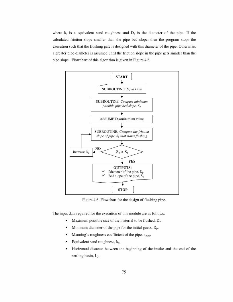
75
where ks is a equivalent sand roughness and Dp is the diameter of the pipe. If the
calculated friction slope smaller than the pipe bed slope, then the program stops the
execution such that the flushing gate is designed with this diameter of the pipe. Otherwise,
a greater pipe diameter is assumed until the friction slope in the pipe gets smaller than the
pipe slope. Flowchart of this algorithm is given in Figure 4.6.
Figure 4.6. Flowchart for the design of flushing pipe.
The input data required for the execution of this module are as follows:
• Maximum possible size of the material to be flushed, Dm,
• Minimum diameter of the pipe for the initial guess, Dp,
• Manning’s roughness coefficient of the pipe, npipe,
• Equivalent sand roughness, ks,
• Horizontal distance between the beginning of the intake and the end of the
settling basin, L2,
START
STOP
SUBROUTINE: Input Data
ASSUME DP=minimum value
SUBROUTINE: Compute the friction slope of pipe, Sf that starts flushing
SUBROUTINE: Compute minimum possible pipe bed slope, S0
So > Sf increase Dp
OUTPUTS: � Diameter of the pipe, Dp � Bed slope of the pipe, S0
YES
NO

76
• Angle between the river and the intake flow directions, �i,
• Bed elevation at the end of the settling basin, El2,
• Bed elevation where the pipe connects to river, El1.
The main outputs are:
• Diameter of the pipe, Dp,
• Bed slope of the pipe, S0.
4.3.1.9 Program Module for the Seepage Analysis
WINDWEIR implements Lane’s creep analysis for the seepage computations. Details of
this method were presented in the related sections in Chapter 3. In this module, the
dimensions of the foundations of the spillway are needed in order to calculate the
corresponding creep length. For that reason, these dimensions are introduced as input to
the module in addition to the hydraulic input data, such as the upstream and downstream
water elevations for different flood discharges. Having calculated the creep length
according to the foundation dimensions, it is compared with the minimum creep length
which depends on the values of the relative permeability of the soil and the net head
occurring between the upstream and downstream of the diversion weir.
The program does not make any modification if the minimum creep length is not satisfied.
Because there are many alternatives that can be done in order to increase the seepage path,
such as increasing the upstream blanket, sheet piling, cutoff walls or some other
specialized precautions. It is the designer’s responsibility to satisfy the seepage condition
by modifying the dimensions of various structural components to increase the creep length
throughout the successive executions of the program.
This module of the program performs seepage analysis by defining the foundation
geometry in the following way: As it is seen in Figure 4.7, the dimensions of the
foundation are described by seven number of points whose elevations and the horizontal
distances between them are required input data for the program. Besides, the upstream
blanket length, Lub, and the height of sheet piling, Hsp are other necessary inputs.

77
Figure 4.7. Definition sketch for the foundation dimensions of the spillway and stilling
basin.
The overall input data required for the seepage analysis are listed below:
• Relative permeability of the soil, C,
• Upstream water surface elevations over the spillway for each flood discharge,
K100, K50, K25, K10, K5,
• Water surface elevations at the riprap section for each flood discharge, Kd100, Kd50,
Kd25, Kd10, , Kd5,
• Crest elevation of the spillway Ks,
• Bottom elevation at the riprap section, Kr,
• Foundation geometry as described above.
The module gives the following outcome:
• Total creep length, Lcr,
• Minimum creep length for no piping, C*Hnet,
• The end result if the structure is satisfactory or not for seepage.
4.3.1.10 Program Module for the Stability Analysis
WINDWEIR performs the stability analysis with respect to the following criteria:
• Stability against uplift,
• Stability against sliding and shear,
• Stability against overturning.
Kr
EL7
Hsp
Kd
Ks
EL1 EL2
EL3 EL4 EL5 EL6
Ls L1 L2 L3 L4 L5 Lub
� Stilling basin
upstream blanket
Sheet piling
y2 y3
y1
K

78
In the stability calculations, the program module follows some general policy. For each
stability analysis, the forces acting on the corresponding structure are calculated and
according to the need of the stability check, also the moments generated by these forces
with respect to critical points of the structure are computed. Then, corresponding safety
criterion is checked whether the structure is safe or not. If the structure is not satisfactory,
the program does not make any alteration in the parameters, such as geometry of the
structure, etc., that affect the safety in order to satisfy the criterion. This is because, there
are many alternatives that can be made to provide the safety. Therefore, the necessary
changes that should be done are left to the designer. The designer is responsible to satisfy
the safety by changing the appropriate variables. For example, foundation elevations can
be changed to increase in the weight of the corresponding structure which increases the
safety. As a result, the designer should make such modifications and performs successive
executions of the program until the desired criteria are satisfied.
4.3.1.10.1 Stability against Uplift
Stability analysis against uplift is carried out both for the stilling basin and settling basin.
Usually a common stilling basin at the toe of the spillway and sluiceway exists as the
result of the energy dissipator calculations. However, sometimes, separate stilling basins
may exist at the downstreams of the spillway and sluiceway. For those cases, foundation
geometries of these stilling basins become different from each other such that stability
calculations against uplift should be performed separately for each part. WINDWEIR
follows the same approach in stability calculations.
Throughout the stability computations against uplift, the factor that threats the safety is the
uplift force produced by seepage phenomenon. Therefore whenever the uplift force needs
to be computed, the corresponding creep length is also computed in order to determine the
uplift force. Therefore, foundation geometry is also required for uplift calculations.
Similar to spillway and its stilling basin’s foundation geometry, intake foundation
geometry is also composed of seven points (see Figure 4.8).
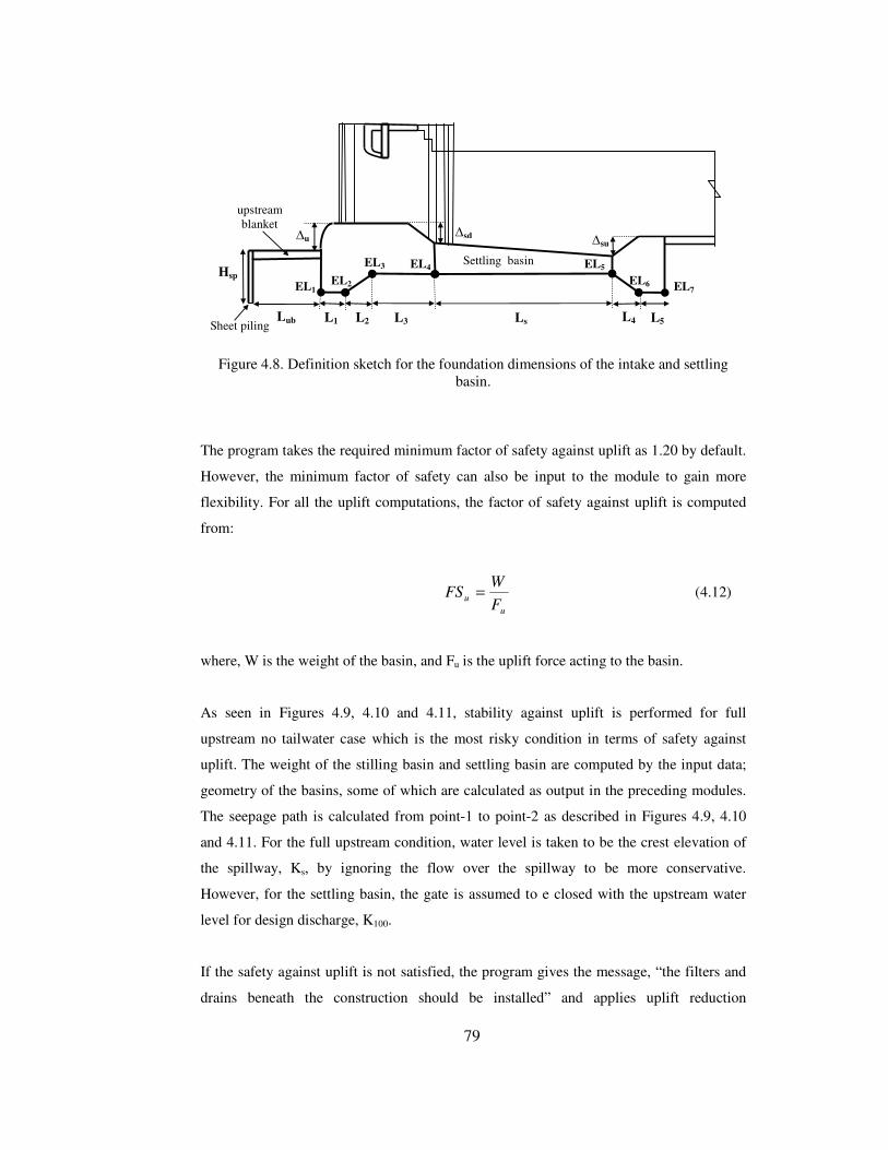
79
Figure 4.8. Definition sketch for the foundation dimensions of the intake and settling
basin.
The program takes the required minimum factor of safety against uplift as 1.20 by default.
However, the minimum factor of safety can also be input to the module to gain more
flexibility. For all the uplift computations, the factor of safety against uplift is computed
from:
uu F
WFS = (4.12)
where, W is the weight of the basin, and Fu is the uplift force acting to the basin.
As seen in Figures 4.9, 4.10 and 4.11, stability against uplift is performed for full
upstream no tailwater case which is the most risky condition in terms of safety against
uplift. The weight of the stilling basin and settling basin are computed by the input data;
geometry of the basins, some of which are calculated as output in the preceding modules.
The seepage path is calculated from point-1 to point-2 as described in Figures 4.9, 4.10
and 4.11. For the full upstream condition, water level is taken to be the crest elevation of
the spillway, Ks, by ignoring the flow over the spillway to be more conservative.
However, for the settling basin, the gate is assumed to e closed with the upstream water
level for design discharge, K100.
If the safety against uplift is not satisfied, the program gives the message, “the filters and
drains beneath the construction should be installed” and applies uplift reduction
Settling basin
EL1 EL2
EL3 EL4 EL5
EL6 EL7
L1 L2 L3 L4 L5 Ls Lub
Hsp
�u �su �sd
upstream blanket
Sheet piling

80
coefficient to the uplift force. Then, the program rechecks the safety criterion. If criterion
is still not satisfied, then the program does not make further modification. As stated
before, the designer is assumed to be responsible for further modifications to provide a
safe solution.
The program module requires the following input data for processing:
• Specific weight of the water, �w,
• Specific weight of the concrete, �conc,
• Uplift reduction coefficient, φ,
• Minimum allowable factor of safety against uplift, FSu,
• Foundation dimensions of the basin,
• Height of the end sill, �,
• Slope of the basin, S0 (required only for settling basin),
• Water elevation in full upstream case,
• Bed elevation at the end of the basin.
The obtained results of the module are:
• Weight of the basin, W,
• Uplift force, Fu,
• Factor of safety against uplift, FSu,
• The end result indicating whether or not the structure is satisfactory against uplift.
4.3.1.10.2 Stability against Shear and Sliding
For the stability against shear and sliding, the overall structure (body + apron) is
considered. The program makes two assumptions in the implementation of the algorithm:
1. The effects of cut off walls and passive resistance are ignored,
2. Spillway body is modeled by an equivalent trapezoidal section.

81
Figure 4.9. Definition sketch for the stability of spillway stilling basin against uplift.
Figure 4.10. Definition sketch for the stability of sluiceway stilling basin against uplift.
Figure 4.11. Definition sketch for the stability of settling basin against uplift.
Kr
Ks
Stilling basin
1 2
Fu
W
Spillway
u1 u2
L �
Kst
1 2
Fu
W Settling basin
Gate closed K100
intake
L
u1 u2
� Kst
Kend
Stilling basin
Ks
Kr 1 2
Fu
W Sluiceways
L
u1 u2
Kst
�
Gate closed

82
Figure 4.12. Definition sketch for the representation of spillway body with a trapezoidal
section.
The equivalent trapezoidal representation of the spillway body is left to the designer.
Therefore, the program requires the crest thickness of the trapezoidal section, tc as input in
order to describe the trapezoidal section (see Figure 4.12). Then, the program models the
overall structure (body +apron) by ignoring the cut off walls as seen in Figure 4.13.
Figure 4.13. Definition sketch for stability against shear and sliding.
The definitions of the forces shown in Figure 4.13 are listed below:
• W : dead loads,
• Fu : Uplift force,
• Fd : earthquake force,
• Fh : hydrostatic force ,
Kst Fh Fw
Fuh Fs W1
Fdh1
Fdh2 Fdh3
Fdv1
Fdv2 Fdv3
W2 W3
Kr
1
Fu
2
3
5
Cut off walls are ignored
Kst
Spillway Body
4
Ks
tc

83
• Fw : upstream dynamic force due to earthquake,
• Fs : lateral active earth pressure,
• Fuh : hydrostatic force acting on the subsurface portion of the spillway due to
seepage.
The program does not consider the effect of ice load in the computations. The seepage
path adjacent to the beneath of the modeled body and apron is computed from point-1 to
point-5. According to the calculated creep length, the hydrostatic pressures at points 2, 3
and 4 are computed and the uplift force, Fu, and the subsurface hydrostatic force, Fuh, are
determined with these uplift pressures. The computation how the seepage pressure is
distributed along the seepage path was described clearly in Chapter 3. If the uplift
reduction was applied in the previous module that deals with the stability against uplift,
the program reduces the uplift force in this module also. The minimum factor of safety
against sliding, FSs, is computed from:
H
VfFS cf
s ΣΣ
=*
(4.13)
where, fcf : friction coefficient between concrete and foundation,
ΣV : total net vertical force acting on the overall structure,
ΣH : total net horizontal force acting on the overall structure.
The minimum factor of safety required against shear and sliding, FSss is computed from:
H
AVfFS sshcf
ss Σ+Σ
=τ5.0*
(4.14)
where, Ash: area of the shear plane,
τs : allowable shear stress in concrete.
The program takes the values of the minimum factor of safeties as below by default
(Yanmaz, 2001):
• For sliding: 1.2,
• For shear and sliding: 3.0.

84
4.3.1.10.3 Stability against Overturning
In this module, only the spillway body is checked against overturning with the calculated
forces in the previous module. The program performs overturning checks for the
following conditions as seen in Figures 4.14, 4.15, and 4.16:
• Full upstream with no tailwater case with respect to heel of the spillway,
• Empty upstream case with respect to heel of the spillway,
• Empty upstream case with respect to toe of the spillway.
For each case mentioned above, the moments created by each force are calculated and the
factor of safety against overturning, FS0 is calculated as:
0M
MFS r
o ΣΣ
= (4.15)
where,
ΣMr : total resisting moments,
ΣMo : total overturning moments.
The program takes the minimum factor of safety to be provided against overturning as 1.5
by default. Having calculated the moments, the base pressures resulting beneath the
spillway body are also checked to be in the allowable range. The base pressures, � , are
calculated by the following equation:
IcM
AV
bs
*�
Σ=σ (4.16)
where,
ΣV : total net vertical force acting on the base of the spillway,
M : the net moment about the centerline of the base,
c : equal to B/2, where B is the base width of the spillway body,
I : moment of inertia of the spillway base equal to (B3/12),
Abs : base area of the spillway.

85
Figure 4.14. Definition sketch for stability against overturning for full upstream no
tailwater case with respect to heel.
Figure 4.15. Definition sketch for stability against overturning for empty upstream case
with respect to heel.
Figure 4.16. Definition sketch for stability against overturning for empty upstream case
with respect to toe.
Kst
Fs W1
Fdh1
Fdv1
heel toe
Kst
Fs W1
Fdh1
Fdv1
heel toe
Kst Fh Fw
Fuh Fs W1
Fdh1
Fdv1
Fu
heel toe
Ks
Ks
Ks

86
The net moment about the centerline of the base can be calculated by the relation
M=ΣV*e , where e is the eccentricity which is equal to (B/2 – x). And the value of x
shown in Figure 4.17 is calculated from:
VMM
x or
ΣΣ−Σ
= (4.17)
where the definitions of the variables are as explained before.
Figure 4.17. Definition sketch for calculating the base pressures.
4.3.1.10.4 Stability of the Sidewalls (Design of the Sidewalls)
The program is capable of design of cantilever type reinforced concrete retaining walls as
the sidewalls. For the analysis of reinforced concrete retaining walls, Rankine’s theory of
earth pressure is used (Craig, 1987). Therefore, the program performs the stability analysis
of the sidewalls by using Rankine’s theory. The active earth pressure is calculated by the
active earth pressure coefficient, Ka, as follows:
θθ
sin1sin1
+−=aK (4.18)
where, is the angle of repose of the soil. And the lateral active earth pressure, pa , in a
cohesionless soil is determined from:
zKp aa **γ= (4.19)
where, �s is the unit weight of the soil and z is the soil depth over the point considered.
ΣΣΣΣV
heel toe
�min �max
M
B c e x

87
The crest elevations of the sidewalls are known from the water level within the energy
dissipation basin. The program determines the crest elevation from the water level at the
end of the hydraulic jump, which is the sequent depth of the jump, y2 as seen in Figure 4.7.
As indicated before, energy dissipators are selected among various alternatives which each
correspond to different flood discharges. Therefore, in a similar way, the maximum value
of y2 among these flow possibilities is selected and incremented by appropriate freeboard
to find the crest elevation of the sidewalls, Ksw, as follows:
)1(2.0 max,2max,2 yyKK ussw +++= (4.20)
where, Kus is the base elevation of the stilling basin and y2,max is the maximum value of y2
(see Figure 4.18).
The program requires the following dimensions of the sidewall that are illustrated in
Figure 4.18 :
• Distance from the soil surface to the ground water table, dgwt,
• Base slab thickness of the sidewall, tslab,
• Thickness of the sidewall, tsw,
• Width of the base slab, Bsw.
Figure 4.18. Definition sketch for the design of the sidewalls.
Stilling basin
Kus
Ksw
Kbs
GWT
tslab
dgwt
tsw
Bsw
y2,max

88
The program performs the stability of the sidewall against sliding with these chosen
dimensions and other related data, such as the angle of repose of the soil, , unit weight of
the soil, �s, etc. The program takes the minimum required factor of safety against sliding
as 1.5 by default. Also, the base pressures are checked to observe if they are in the
allowable limits. Therefore, all the forces acting on the sidewall are calculated and the
stability checks are performed as an ordinary retaining wall. If the sidewall stability is not
satisfied, then the program has an option of increasing the width of the base slab, Bsw until
the stability is provided.
4.3.1.11 Program Module for the Computation of the Total Cost of the Diversion
Weir
After the overall dimensions of the diversion weir are determined, then the total cost of the
structure is evaluated from the designed dimensions of each structural component. The
following components are involved in the cost computations:
• Intake,
• Spillway,
• Stilling basins,
• Gates,
• Sidewalls,
• Guiding wall,
• Riprap,
• Flushing canal,
• Diversion facility.
For the components; intake, spillway, stilling basins, sidewalls, guiding wall, the concrete
volume, flushing pipe are calculated from the designed dimensions of these structures and
this volume is multiplied by the unit cost of concrete which is an input value for the
program. For the cost of the gates at the intake and sluiceway, the weight of the total steel
used from the gate dimensions is multiplied by the unit cost of steel which is also an input
value for the program. The cost of the riprap is calculated by multiplying the volume of
the riprap by the corresponding unit cost. Finally, all these costs are summed up to find the
total cost of the diversion weir.

89
The volume of the spillway body is computed from its equivalent trapezoidal
representation given by the user, and the total concrete volume of USBR stilling basins are
determined from the following equations (Seçkiner, 1999):
Volume of USBR type 1 stilling basin for 1 meter slab thickness, Vsb1:
)107.12487.111521.0( 12
111 −+−= rrsb FFLyV (4.21)
Volume of USBR type 2 stilling basin for 1 meter slab thickness, Vsb2:
)3.4022.04
( 22
2
21
2 yyy
LVsb ++= (4.22)
Volume of USBR type 3 stilling basin for 1 meter slab thickness, Vsb3:
)7.235.04
( 22
42
3
21
3 yHHy
LVsb +++= (4.23)
in which, 6
)4( 113
rFyH
+= and
9)9( 11
4rFy
H+
=
Volume of USBR type 4 stilling basin for 1 meter slab thickness, Vsb4:
)1.675.1
( 22
4
21
4 yHy
LVsb ++= (4.24)
where, L is the width of the basin, y1 and y2 are the conjugate depths of the hydraulic
jump, respectively, and Fr1 is the Froude number at the toe of the spillway.
4.3.2 Capabilities of the Program
WINDWEIR is developed to perform the design of the diversion weirs having overflow
spillway and sidewise intake. The program has built-in ability to solve two different types

90
of problem on the subject of the diversion weirs with sidewise intake and overflow
spillway:
1. The overall design of the diversion weir,
2. Optimization of the bottom width of the main irrigation canal.
The program was coded in many sub-modules, each of them was explained in the
preceding sections. All these sub-modules are assembled to perform the overall design of
the diversion weir. Each of these sub-modules are linked in the appropriate order as seen
in the flowchart presented in Figure 4.19.
The program can also find the optimum bottom width of the main irrigation canal by an
iterative cost analysis. The bottom width at the beginning of the irrigation canal, B, is
initialized with 1.0 meter and the overall design of the diversion weir is done. Then, the
value of B is incremented and the corresponding overall design is renewed. For each
bottom width, the designed diversion weir is checked against safety for all conditions as
described in preceding sections. If the diversion weir is safe under all conditions, then this
is an acceptable design to be considered in the cost analysis. This computation is repeated
until the bottom width that yields the minimum cost among the acceptable designs is
found. The flowchart representing this procedure is presented in Figure 4.20.
4.3.3 Numerical Methods Utilized in the Program
Throughout the computation processes, many nonlinear equations are needed to be solved
for the desired variables. There are many numerical techniques in the literature to find the
roots of a nonlinear equation. The most common algorithms which are used in the
computer programming can be listed as follows:
• Bracketing methods
o The bisection method of Bolzano
o Regula Falsi method
• Slope methods
o Newton-Raphson method
o Secant method

91
Figure 4.19. Flowchart of the overall design of the diversion weir.
START
STOP
MODULE : Input Data
MODULE : Intake design
MODULE : Determination of the Spillway and Sluiceway Dicharges
MODULE : Design of the Energy Dissipators
MODULE : Seepage Analysis
MODULE : Stability Analysis
MODULE : Design of Sidewalls
MODULE : Design of upstream levees
MODULE : Riprap Design
MODULE : Flushing canal design
MODULE : Design of diversion facility
OUTPUTS: � Overall dimensions of Diversion weir
MODULE : Cost computations

92
Figure 4.20. Flowchart representing the optimization of the bottom width at the beginning
of main irrigation canal.
START
STOP
MODULE: Input Data
ASSUME : B=1.0 m.
MODULE : Design of the whole Diversion weir
Are all checks satisfied ?
MODULE : Add the current design to the list of the acceptable designs
CT,dw(i +1) > CT,dw(i)
OUTPUTS: � Optimum bottom width of the main
irrigation canal, Bop � List of summary of all trials � Overall dimensions of the diversion weir
which corresponds to the optimum bottom width
inrease the value of B
YES
NO
YES
NO

93
Among these methods, WINDWEIR implements Secant method to solve the nonlinear
equations expressed through the design of the diversion weir. The reason behind this
choice is that Secant method converges to the root faster when compared with the
bracketing methods. It is also as fast as Newton-Raphson method, but it is an easier
algorithm to implement.
All the nonlinear equations can be solved by using Secant method provided that the
related equation itself along with its first and second derivatives are continuous functions
over the range of its roots. The program calculates all the desired variables, such as critical
depth, yc, normal depth y0, alternate depths, conjugate depths, etc by implementing the
algorithm of Secant method. The details of Secant method can be found in any book
related to numerical analysis.
4.3.4 Visual Interface of the Program
WINDWEIR has visual user-interface as a typical computer program that works under
Microsoft Windows operating system. Overall user-interface of the program is composed
of three groups:
1. User interface related to the input data,
2. User interface related to the computation process,
3. User interface related to the outputs (results).
A brief user-manual of the program in parallel with the main screenshots of the user-
interfaces is presented in Appendix A.

94
CHAPTER 5
APPLICATION
5.1 Definition of the Problem
Hydraulic design of a diversion weir having overflow spillway and sidewise intake is to
be performed by the use of WINDWEIR. The irrigation demand is diverted by the
sidewise intake which is located at the right bank. The portions of the river at the upstream
of the structure are assumed to be trained to have a suitable trapezoidal cross-section.
Optimum bottom width of the main irrigation canal is determined by making cost analysis
by WINDWEIR. In addition to these computations, the thickness of the stilling basin,
length of the upstream blankets and the height of the sheet piling is varied such that the
variation of the optimum bottom width of the main irrigation canal with respect to these
changes are examined.
5.2 Related Information
The related input information is given as below:
• The irrigation discharge is 4.4 m3/s,
• The bottom slope of the main irrigation canal is 0.0004,
• The bottom elevation at the beginning of the main irrigation canal is 650.10 m,
• The length of the diversion canal is 225 m,
• Relative permeability of soil , C=5,
• Friction coefficient between the structure and foundation, f=0.75,
• Manning’s roughness coefficients are nriver =0.03 , nconc=0.016,
• The specific weights are �conc=24 kN/m3, and �w=10 kN/m3, • Allowable shear stress between the spillway and foundation =1500 kN/m2,

95
• Allowable compressive strengths: Concrete: �ac=4000 kN/m2, and Foundation:
�af=3000 kN/m2,
• The seismic earthquake coefficients: Horizontal: kh=0.06, Vertical: kv=0.03,
• There will be two sluiceways with suitable dimensions,
• Bed elevation at the spillway axis, Kst =649.20 m,
• Bed elevation at the riprap section, Kr=649.07 m.
The water surface profile computations along the river site are performed by HEC-RAS
(USACE, 1998) computer package. The results of these computations which are required
for WINDWEIR as input data are tabulated in Table 5.1.
Table 5.1. Input data obtained from the results of the water surface profile computations
along the river site.
Flood discharge name
Discharge (m3/s) Water surface elevations at the riprap section (m)
Q100 384 652.20 Q50 324 651.98 Q25 294 651.85 Q10 254 651.67 Q5 204 651.40
The unit cost values taken in the determination of the total cost of the structure are as
follows:
• Unit cost of the concrete works for the spillway, stilling basin, etc., is taken as
$132.91/m3 (Seçkiner, 1999),
• Unit cost of steel appurtenances for the steel gates is taken as 6$ /kg,
• Unit cost of riprap is taken as 16$/m3.
5.3 Computations and Discussions
WINDWEIR was executed by inserting the required data presented in the previous
section. Mainly, the program was executed for the following three objectives:
• To examine the effects of the thickness of the stilling basin, tsb,
• To examine the effects of the length of the upstream blanket, Lub,
• To examine the effects of the height of the sheet piling, Hsp.

96
For the first part, the cost optimization with respect to the bottom width of the main
irrigation canal was made for the following values of the stilling basin slab thicknesses:
tsb=0.8 m, tsb=0.9 m, tsb=1.0 m, tsb=1.1 m All the other variables are taken as constant
through these alternatives in order to examine the effect of the slab thickness of the basin.
For each of these values, the curves of cost versus bottom width of the irrigation canal, B,
are plotted as seen Figure 5.1. The triangle symbol on the curves represents the boundary
of the acceptable designs from which all of the checks including the stability analysis are
satisfied. As expected, smaller bottom widths of the irrigation canal causes higher water
elevations at the upstream of the diversion weir. This causes stability problems as a result
of high hydrostatic and uplift forces. When the slab thickness of the stilling basin is
increased, the acceptable designs start at smaller bottom widths of the main irrigation
canal, because the stability of the stilling basin against uplift is satisfied by increasing the
stilling basin weight. As a result, it is seen from Figure 5.1 that, the acceptable design
limit shifts leftwards by the increase of the thickness of the stilling basin.
For the second part, the effect of the upstream blanket is examined. The length of the
upstream blankets are increased by 4 m. Figure 5.2 shows that the acceptable design limit
shifts leftward by increasing the length of the upstream blanket. As a result, if the length
of the upstream blanket increases, safety of the structure increases because smaller uplift
force is generated due to the increase in creep length.
For the last part of the problem, the effect of the height of the sheet piling is examined for
the values of 2, 4, and 6 m by holding all the other variables as constant. As expected,
deeper sheet piling reduces the uplift forces by increasing the seepage path, resulting in
shifting of the acceptable design limit leftwards. This situation is clearly seen in Figure
5.3.
Among these analyses, it can be resulted that, uplift is an important problem which
threatens stability by the uplift forces. Therefore, the stability against overturning or shear
and sliding play secondary roles in the stability requirements. This is an expected result
that the weight of the spillway body is usually enough to resist against overturning and
sliding tendencies. However, the weight of the basin may not be enough to resist against
the uplift forces due to seepage. As the second result from these analyses, to increase the
slab thickness of the basin is a reasonable precaution to satisfy the stability against uplift.

97
Figure 5.1. Cost versus main irrigation canal width for various thicknesses of stilling basin (Lub=8.0 m, Hsp=2.0 m).

98
Figure 5.2. Cost versus main irrigation canal width for various lengths of upstream blanket (tsb=1.0 m, Hsp=2.0 m).

99
Figure 5.3. Cost versus main irrigation canal width for various heights of sheet piling (tsb=1.0 m, Lub=8.0 m).
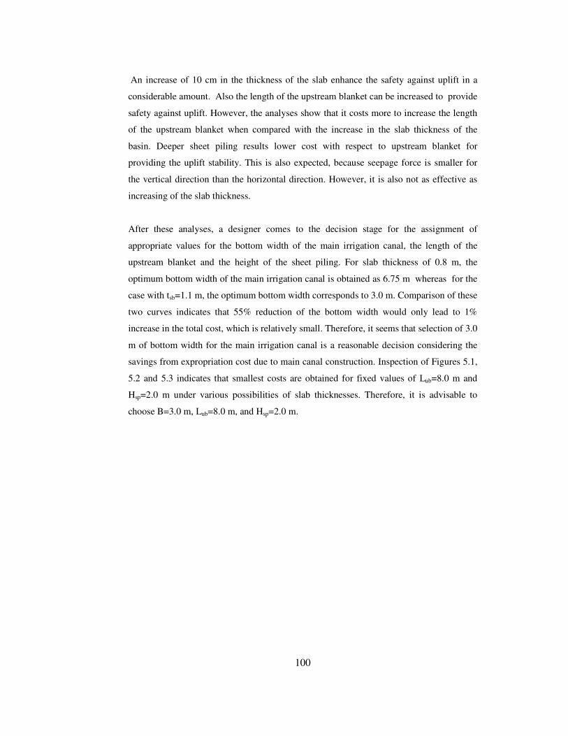
100
An increase of 10 cm in the thickness of the slab enhance the safety against uplift in a
considerable amount. Also the length of the upstream blanket can be increased to provide
safety against uplift. However, the analyses show that it costs more to increase the length
of the upstream blanket when compared with the increase in the slab thickness of the
basin. Deeper sheet piling results lower cost with respect to upstream blanket for
providing the uplift stability. This is also expected, because seepage force is smaller for
the vertical direction than the horizontal direction. However, it is also not as effective as
increasing of the slab thickness.
After these analyses, a designer comes to the decision stage for the assignment of
appropriate values for the bottom width of the main irrigation canal, the length of the
upstream blanket and the height of the sheet piling. For slab thickness of 0.8 m, the
optimum bottom width of the main irrigation canal is obtained as 6.75 m whereas for the
case with tsb=1.1 m, the optimum bottom width corresponds to 3.0 m. Comparison of these
two curves indicates that 55% reduction of the bottom width would only lead to 1%
increase in the total cost, which is relatively small. Therefore, it seems that selection of 3.0
m of bottom width for the main irrigation canal is a reasonable decision considering the
savings from expropriation cost due to main canal construction. Inspection of Figures 5.1,
5.2 and 5.3 indicates that smallest costs are obtained for fixed values of Lub=8.0 m and
Hsp=2.0 m under various possibilities of slab thicknesses. Therefore, it is advisable to
choose B=3.0 m, Lub=8.0 m, and Hsp=2.0 m.

101
CHAPTER 6
CONCLUSIONS AND RECOMMENDATIONS
A user friendly computer program which has a visual user-interface is developed for the
optimum design of diversion weirs with reference to all corresponding hydraulic
computations in an integrated manner. It enables the designer to assess various dimensions
of the structure from viewpoints of safety and economy. The program covers the type of
diversion weirs having overflow spillway and sidewise intake.
The program should be executed on the assumption that the site is ready for construction
with excavation, filling and foundation treatments were completed. Also, the soil beneath
the structure is assumed to be homogenous in the design algorithms of WINDWEIR.
Almost all of the structural components of a diversion weir with sidewise intake are
considered by the program. Each component is analyzed for a particular hydraulic
condition with desired conformity and the overall dimensions of this component are
determined by satisfying the necessary stability criteria. Optimum design can be selected
among several alternatives by executing the program in an iterative manner.
The program is also able to perform cost analysis in order to determine the optimum
design with respect to the bottom width at the beginning of the main irrigation canal. The
capabilities of the program enables a designer to solve different types of problems related
to diversion weirs, such as planning and design of irrigation systems. In this manner,
optimum irrigation discharge which corresponds to maximum crop yield of an irrigation
system can be obtained by performing cost analysis including the total costs of both
diversion weir and the irrigation system by successive execution of the program.
The program is specifically developed for diversion weirs having an overflow spillway.
As a suggested further study, the scope of the program can be extended to consider other
types of diversion weirs, such as gated diversion weir and the diversion weirs with drop

102
and frontal intakes. Also the optimization algorithms can be sophisticated in a manner that
the design of the irrigation system can also be added to the program.
It is believed that a design engineer can evaluate various alternatives for the dimensions of
a diversion weir by successive executions of the program and select the feasible design by
considering the safety and economy. The designer may then achieve the final design
among these alternatives by examining the corresponding outputs of the program by
considering also the local site conditions and the purpose of the project.

103
REFERENCES
Arslan, M., 1996, “Dolu Gövdeli ve Kapaklı Ba�lamalar”, Civil Engineering Department, Gazi University, Ankara. Baban, R. B., 1995. “Design of Small Diversion Weirs”, New York: John Wiley and Sons. Bayazıt, M., 1971. “Loose Boundary Hydraulics”, Publications of �stanbul Technical University, No: 835, �stanbul (in Turkish). Breusers, H.N.C., and Raudkivi, A.J., 1991. “Scouring-Hydraulics Structures Design Manual 2”, International Association for Hydraulic Research, A. A. Bakema, Rotterdam/Brookfield, Holland. Chow, V.T., 1959. “Open Channel Hydraulics.”, McGraw Hill, New York.
Craig, R.F., 1987. “Soil Mechanics”, Melbourne: Van Nostrand Reinhold. Çeçen K., 1962. “Vah�i Derelerden Su Alma”, Publications of �stanbul Technical University, No: 485, �stanbul (in Turkish). Çulcu I., 2000. “Regülatörlerin Hidrolojik ve Morfolojik Yönden �rdelenmesi”, Unpublished M.Sc. Thesis, Civil Engineering Department, Gazi University, Ankara (in Turkish).
Davis, H., 2002. “Visual Basic.NET Programming”, Sybex. DS�, 1998. “Design Criteria for Diversion Weirs”, Ankara (in Turkish): Publications of the Turkish State Hydraulic Works. French, R.H., 1987. “Open Channel Hydraulics”, Singapore: McGraw Hill. Garbrecht, G., 1963. “Frontale Wasserfassung in Geschiebeführenden Flüssen”, DieBautechnik, No.5, pp.162-167 (in German).

104
Habermaas, F., 1955. “Sediment Motion in Channel Bifurcations”, Wasserkraft und Wasserwirthcraft, No.59 and 10 (in German). Henderson, F.M., 1966. “Open Channel Flow”, New York: Mac Millan Publishing Co. Inc. Kashef, A.I., 1987. “Groundwater Engineering”, Singapore: McGraw Hill.
Microsoft Corporation, 2002. “Microsoft Visual Basic .NET Language Reference”, Microsoft Press, USA. Özbek, T., 1989, “Yanal Su Alma Yapılı Dolu Gövdeli Ba�lamalarda Ayırma Duvarının Sürüntü Maddesine Etkisi”, Ankara (in Turkish): Publications of the Turkish State Hydraulic Works. Pala, Z.,2003. “Visual Basic .net”, Türkmen Kitabevi, �stanbul (in Turkish). Seçkiner, G., 1999. ”Computer Assisted Lay-out Design of Concrete Gravity Dams”, Unpublished M.Sc. Thesis, Civil Engineering Department, Middle East Technical University, Ankara. Sungur, T., 1988. “Hydraulic Structures-Vol.2: Diversion Weirs”, Ankara (in Turkish): Publications of the Turkish State Hydraulic Works. Sümer, B. M., 1977. “Settlement of Solid Particles in Open Channel Flow”, J. Hydraulics Division, ASCE, Vol. 103, No. HY11, pp. 323-327. �endil, U., 1962. “Study of Sediment Conditions at Direct Intakes”, Unpublished M.Sc. Thesis, CE Dept., METU, Ankara. USACE, 1998. “HEC-RAS (User’s Manual: Version 2.2)”, US Army Corps of Engineers Hydrologic Engineering Center, Davis, California. USBR, 1952. “Canals and related structures.”, Design and Construction manual.(3). USBR, 1987. “Design of Small Dams”, Third Edition, Washington: Water Resources Technical Publication.

105
Yanmaz, A. M., and Cihangir, E., 1996. “A Computer Program for Hydraulic Design of Diversion Weirs with Lateral Intakes”, Turkish J. of Engineering and Environmental Sciences, 20, pp. 1-6.
Yanmaz, A. M., and Özaydın, V., 2000. “An approach to Optimum Hydraulic Design of Diversion Weirs”, CD-ROM Proc. Watershed Management Conference, ASCE, Fort Collins, Colorado, USA. Yanmaz, A. M., and Bulut, F., 2001. “Computer Aided Analysis of flow Through River Bridges”, CD-ROM Proceedings of World Water and Environmental Resources Congress, ASCE, Orlando, USA.
Yanmaz, A. M., 2001. “Applied Water Resources Engineering”, Metu Press, Ankara. Yanmaz, A. M., 2002. “Köprü Hidroli�i”, Metu Press, Ankara (in Turkish).

106
APPENDIX A
USER-MANUAL FOR WINDWEIR
A.1 Main Window of WINDWEIR
After an introductory screen appears, the main window of the program comes to the
screen as seen in Figure A.1. This window is the major user-interface through which all
the desired manipulations are performed. It appears during the running of the program in
the computer memory such that when it is closed, then the program ends. There are five
main menu items on this window. Each menu item includes some sub-menu items, which
are related to the different modules of the program. These major menu items are named as
follows in order of their appearances from the left to the right on the window:
• File,
• Input Data,
• Run,
• Outputs,
• Help.
Figure A.1. Main window of WINDWEIR.

107
Just at the bottom of the main menu items, there exists a toolbar with some buttons which
are shortcuts for mostly used sub-menu items. At the bottom of the window, there is a
status bar which includes some information about the working program, such as the
project title and the location of the project file on disk.
A.2 Menu Items in WINDWEIR
Since there are many actions that can be performed in the program, the user-interface
contains many menu items. Therefore, all of these menu items are grouped according to
their relation to the sub-modules of the program. Each menu item, which forms the main
user-interface is explained in the following subsections.
A.2.1 Menu Items Related to the File Management
Under the menu item, named “File”, there exists seven sub menu-items (see Figure A.2),
which are all explained as follows:
Figure A.2. Menu items related to the file management.
• New Project : By clicking this menu item, a small window appears in order to
initiate a new project (see Figure A.3). There are two options that can be selected.
The first one is to start a project for the design of the whole diversion weir and the

108
second one is to start a project for the design of the selected component of the
diversion weir.
Figure A.3. Window for selecting the project type.
After the desired option is selected, the program starts such that all the variables in
the program are assigned to their default values. The following part of the manual
includes the explanations related to the design of whole diversion weir case. For
the other options, the user-manual included in the program should be followed.
• Open Project : By clicking this menu item, a window for the selection of the
project files appears and the project file to be opened is chosen by the user. The
project file extension of WINDWEIR is “.dwr”.
• Save Project : This menu item saves the working project on the program. If this is
the first time to save the project, a new window appears such that the location and
the name of the project file to be saved are required. Otherwise, the project is
saved over the existing project file.
• Save Project As : If the project is desired to be saved on another location than the
existing location, this menu item is used.

109
• Delete Project : This menu item deletes the selected project from the disk.
• Project Summary : By this window, some information about the project can be
entered, such as the name of the project engineer, title of the project or some
comments about the project.
• EXIT : This menu item ends the program by removing the executing file from the
computer memory.
A.2.2 Menu Items Related to the Input Data
There are many input data required for the design of a diversion weir. Therefore, all of
these are grouped for the sake of simplicity (see Figure A.4). These input data are grouped
under following sub-menu items:
Figure A.4. Menu items related to the input data.
• Main Data : This window groups the input data related to main irrigation canal and
the river. Also the flood discharges for various return periods and the corresponding
tailwater surface elevations are entered through this window.

110
• Intake Data : The window which appears after clicking on this menu item deals with
the input data related to the design of the intake. This group of data are also
subdivided into two such that one of them groups the input data related to the plan
view of the intake, and the other one groups the input data related to the profile view
of the intake as follows:
o Plan Geometry : The required input data that are illustrated in the plan view
of the intake are entered on this window.
o Profile Geometry : On this window, the required input data that are illustrated
in the profile view of intake are entered. The foundation geometry of the
intake is also described on this window. The foundation elevations can be
entered by the slab thicknesses or by directly the elevation values. The user
selects the desired way by available radio buttons (see Figure A.5).
Figure A.5. Input data window for intake profile.

111
• Spillway and Sluiceway Data : Similar to the input data related to the design of the
intake, the input data on spillway and sluiceways are also divided into two sub-groups
as cross-section view, and profile view, which are described as follows:
o Cross-section Geometry : The input data illustrated in the cross-section
geometry of the spillway and sluiceways are entered on this window. There is
also an option of viewing the plan view of the spillway and sluiceways on this
window by clicking the corresponding label on the window. In case of the
existence of a bridge over the spillway, which is the default case, the
corresponding checkbox is checked in order to enter the input data related to
the bridge, such as discharge contraction coefficients due to the bridge piers
and abutments, etc. If there is not a bridge over the spillway, the entrance of
the bridge data are not allowed by the program (see Figure A.6).
Figure A.6. Input data window for spillway and sluiceway cross section.

112
o Profile Geometry : The input data illustrated in the profile view of the
spillway and sluiceways are entered on this window. Similar to the case of
the intake, the foundation geometry can be described by entering the slab
thicknesses or the elevation values. The program assumes the same
foundation profile for the spillway and sluiceways. However, due to the
hydraulic limitations as stated in Chapter 3, these elevations may be different
for spillway and sluiceway foundations.
• Sidewalls : This menu item brings the window related to the design of the sidewalls
on the screen. All the required data are entered on this window. There is also an
option of increasing the bottom width of the retaining wall to satisfy the safety
criteria. If this option is selected, the program increases the bottom width until the
desired safety is satisfied. In that case, the entered bottom width value is assumed to
be the initial value for the iteration. If this option is not selected, then the program
does not make any iteration to satisfy the safety criteria. It only reports the result.
• Upstream levees and appurtenant facilities : This menu item brings the window
related to the input data for the design of the upstream levees and appurtenant
facilities. Input data regarding the design of the ripraps and the flushing pipe are also
entered on this window.
• Diversion facility : Input data related to the design of the diversion facility are entered
on the window appearing after clicking this menu item. The diversion canal design
discharge is selected among the flood discharges, which are entered at the main data
window.
• Material and unit cost data : This window contains three groups of data, which are
material data, safety criteria, and the unit cost values.
After entering the input data, they must be activated by pressing the button named
“APPLY THE DATA”. By doing so, the entered data are assigned to the corresponding
variables of the program. If the data are not activated, the program will give error during
the execution.

113
A.2.3 Menu Items Related to the Computation
Under the menu item named “Run”, there is only one menu item named as “Start
Computation”. This menu item brings the computation window on the screen. On this
window, there are two options for the computation type. The first one is for analyzing the
whole diversion weir and the second one is for the optimization of the bottom width at the
entrance of the main irrigation canal. The first option is the default one. If it is selected,
the computation is started by pressing the button named “START COMPUTATION” (see
Figure A.7).
Figure A.7.Window for the selection of the computation type.
During the computation process, a window appears, which shows the computation status
by giving appropriate messages (see Figure A.8). If there is an error in the computation,
the corresponding error message is also displayed on this window. The end of the
computation is understood by the message “COMPUTATION ENDS”. This means that
computation is performed successfully without any error and the outputs are ready for
examining. This window is closed by pressing the button named “CLOSE” and then the
main window appears for inspection of the results. This is done through the menu items
grouped in the main menu item named “Outputs”. Details of these menu items related to
outputs are explained in the following section.

114
Figure A.8. Window related to the computation processes.
A.2.4 Menu Items Related to the Outputs
Since there are many structural components in a diversion weir, there exists many results
related to each component. Therefore, all the results are grouped under the major menu
item named “Outputs” to be examined (see Figure A.9).
Figure A.9. Menu items related to the outputs.

115
Each window is brought by these menu items which contain three menu items (see Figure
A.10).
Figure A.10. A typical output window displaying printout options.
• Printout : Under this menu item, there are five sub-menu items related to the
print-out capabilities of the program as shown in Figure A.10. They are
summarized as follows:
o Page Setup : This menu item brings a window for changing the page setup
values, such as the orientation of the page and the margins, etc.
o Print Preview : This menu item previews the page to be printed.
o Print : The window showing the print-out features appears by clicking this
menu item. The button named “OK” is pressed on this window to start
printing.
o Print to File : This menu item brings a window for exporting the results to
different formats, such as a text file. “File Txt (.*txt)” from the options
“Save as type” is selected to export the results to a text file by entering the
name and location of the file to be exported. Some additional formats,
such as a web page format are also available for exporting the results.

116
o Send E-mail : By using this menu item, the results can be sent to another
user via e-mail.
• Tables : This menu item contains available tabular results of the designed
component. Some components may have a single tabular result whereas some
may have more than one tabular result. The desired results can be accessed on the
same window by selecting the corresponding sub-menu item under this menu (see
Figure A.11). All the components have at least one tabular result.
Figure A.11. A typical output window for the selection of an available tabular output.
• Graphs : This menu item brings the list of the graphical outputs for the results of
the corresponding component. However, all the components do not have a
graphical output. In these cases, this menu item becomes unavailable. Figure A.12
shows a typical window for the selection of an available graphical output. When
the desired graphical output is selected, a new window displaying the
corresponding graphical result appears (see Figure A.13).
In the windows displaying graphical outputs, there are also three menu items:
o Printout : By this menu item, the printout of the graph is obtained.
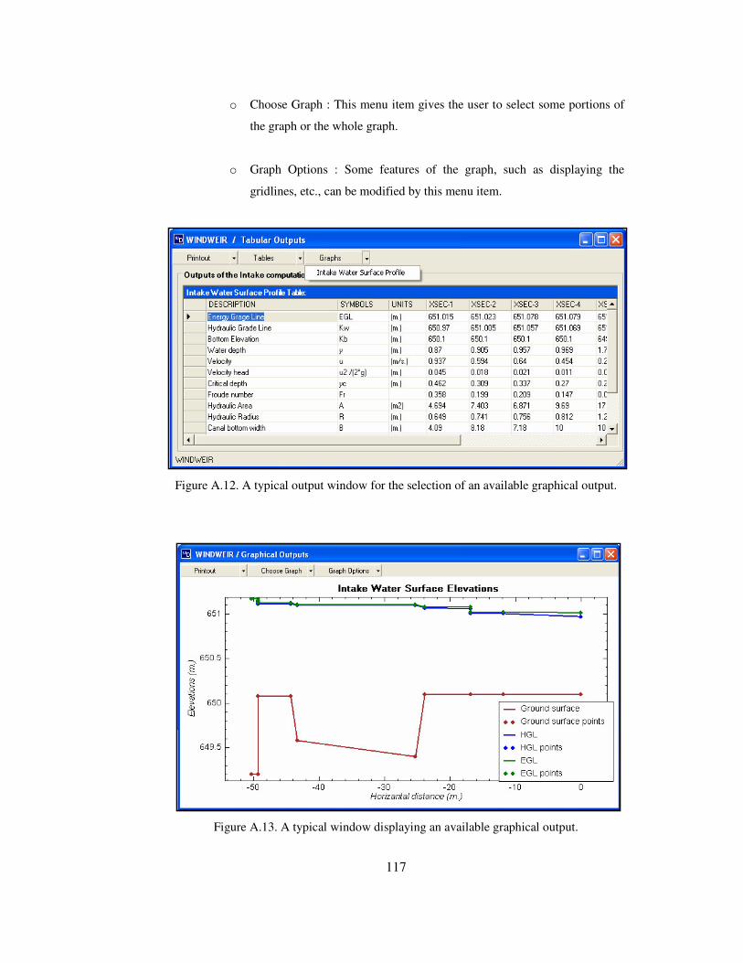
117
o Choose Graph : This menu item gives the user to select some portions of
the graph or the whole graph.
o Graph Options : Some features of the graph, such as displaying the
gridlines, etc., can be modified by this menu item.
Figure A.12. A typical output window for the selection of an available graphical output.
Figure A.13. A typical window displaying an available graphical output.

118
All the sub-menu items under the major menu item, “Outputs” on the main window of the
program give the following outputs:
• Intake Hydraulics Computations, • Spillway and Sluiceway discharges and energy, • Seepage Analysis results,
• Stability Analysis results,
• Sidewalls Stability Analysis Results,
• Crest elevation of upstream levees,
• Diversion Facility,
• Appurtenant facilities,
• Cost computations,
• Optimization results.
Menu item, “Optimization results”, is only available if the computation for the
minimization of the total cost by optimizing the bottom width at the entrance of the main
irrigation canal is performed.
A.2.5 Menu Items Related to the Help
This menu item is used in order to access help and information about the program. Also
e-mail address of the developer of the program can be obtained on the window appearing
as a result of clicking the sub-menu item, “About” under the major menu item, “Help”.
The developer of the program can be reached through this e-mail address for any
discussion about the program.

119
APPENDIX B
SOURCE CODE OF WINDWEIR
'*---------------------------------------------------------------------------------------------------------------------------------* '| CLASS-1: Class1.vb | '| (Hydraulic Computations) | '| (This is the core of the program) | '*---------------------------------------------------------------------------------------------------------------------------------* Imports System.Math Imports dweir_code.General_Hydraulic_Functions Imports dweir_code.General_Hydraulic_Functions.OCH_func Imports dweir_code.Appurtenant_fac Imports dweir_code.cost_computations Imports dweir_code.intake_design Imports dweir_code.levees_and_diversion Imports dweir_code.splw_slcw_design Imports dweir_code.stability_analysis Imports dweir_code.computations.error_hand '************************************************************* '* General note: all input data classes were implemented * '* with copy constructors; however other classes were * '* implemented with copy constructors only when needed. * '************************************************************* Namespace General_Hydraulic_Functions #Region "Data structures" 'computation information structure <Serializable()> Public Class computation_information 'in order to give information about computation Public percent As Single Public message As String Public state As Byte '0:normal comp, 1:error 2:warning 3:accepted (these will match some colors) Public Sub New(ByVal inp As computation_information) 'copy constructor Me.percent = inp.percent Me.message = inp.message Me.state = inp.state End Sub Public Sub New() End Sub End Class 'stilling basin data for determining details of stilling basin type <Serializable()> Public Class stillingbasin Public type As String Public L As Single Public delta As Single 'delta is same as delta_usbr; delta is the sill height found from energy equation (min sill height) Public delta_usbr As Single 'delta_usbr is sill heigh proposed by USBR, if deltausbr>delta delta should be used (because delta is theoretical min value Public B As Single Public y1 As Single Public y2 As Single Public y3 As Single Public Fr1 As Single Public u1 As Single Public TW As Single Public n_chute_blocks As Integer Public n_baffle_piers As Integer Public vol_chute_blocks As Single
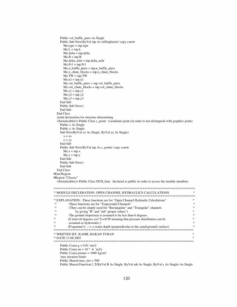
120
Public vol_baffle_piers As Single Public Sub New(ByVal inp As stillingbasin) 'copy constr Me.type = inp.type Me.L = inp.L Me.delta = inp.delta Me.B = inp.B Me.delta_usbr = inp.delta_usbr Me.Fr1 = inp.Fr1 Me.n_baffle_piers = inp.n_baffle_piers Me.n_chute_blocks = inp.n_chute_blocks Me.TW = inp.TW Me.u1 = inp.u1 Me.vol_baffle_piers = inp.vol_baffle_piers Me.vol_chute_blocks = inp.vol_chute_blocks Me.y1 = inp.y1 Me.y2 = inp.y2 Me.y3 = inp.y3 End Sub Public Sub New() End Sub End Class 'point decleration for structure determining <Serializable()> Public Class c_point 'coordinate point (in order to not distinguish with graphics point) Public x As Single Public y As Single Sub New(ByVal xx As Single, ByVal yy As Single) x = xx y = yy End Sub Public Sub New(ByVal inp As c_point) 'copy constr Me.x = inp.x Me.y = inp.y End Sub Public Sub New() End Sub End Class #End Region #Region "Classes" <Serializable()> Public Class OCH_func 'declared as public in order to access the module members '************************************************************************************** '* MODULE DECLERATION: OPEN CHANNEL HYDRAULICS CALCULATIONS * '************************************************************************************** '* EXPLANATION: -These functions are for "Open Channel Hydraulic Calculations" * '* -These functions are for "Trapezoidal Channels" * '* (They can be simply used for "Rectangular" and "Triangular" channels * '* by giving "B" and "mh" proper values") * '* -The ground slope(teta) is assumed to be less than 6 degrees. * '* (if teta<=6 degrees cos^2>=0.99 meaning that pressure distribution can be * '* assumed as hydrostatic.) * '* (P=gamma*y ---> y:water depth (perpendicular to the canal(ground) surface) * '************************************************************************************* '* WRITTEN BY: KAMIL HAKAN TURAN * '* DATE:13.08.2003 * '************************************************************************************* Public Const g = 9.81 'm/s2 Public Const nu = 10 ^ -6 'm2/s Public Const pwater = 1000 'kg/m3 'max iteration limits Public Shared max_iter = 500 Public Shared Function f_T(ByVal B As Single, ByVal mh As Single, ByVal y As Single) As Single

121
Return (B + 2 * (mh * y)) End Function Public Shared Function f_A(ByVal B As Single, ByVal mh As Single, ByVal y As Single) As Single Return ((B + f_T(B, mh, y)) / 2 * y) End Function Public Shared Function f_P(ByVal B As Single, ByVal mh As Single, ByVal y As Single) As Single Return (B + 2 * (((mh * y) ^ 2 + y ^ 2) ^ 0.5)) End Function Public Shared Function f_R(ByVal B As Single, ByVal mh As Single, ByVal y As Single) As Single Return (f_A(B, mh, y) / f_P(B, mh, y)) End Function Public Shared Function f_Dy(ByVal B As Single, ByVal mh As Single, ByVal y As Single) As Single Return (f_A(B, mh, y) / f_T(B, mh, y)) End Function Public Shared Function f_Qmann(ByVal B As Single, ByVal mh As Single, ByVal y As Single, ByVal n As Single, ByVal So As Single) As Single Return (f_A(B, mh, y) / n * (f_R(B, mh, y) ^ (2 / 3)) * (So ^ 0.5)) End Function Public Shared Function f_flow(ByVal Fr As Single) As String If Round(Fr, 2) < 1 Then Return "subcritical" ElseIf Round(Fr, 2) = 1 Then Return "critical" Else Return "supercritical" End If End Function Public Overloads Shared Function f_u(ByVal Q As Single, ByVal A As Single) As Single Return (Q / A) End Function Public Overloads Shared Function f_u(ByVal Q As Single, ByVal y As Single, ByVal mh As Single, ByVal B As Single) As Single Return (Q / f_A(B, mh, y)) End Function Public Overloads Shared Function f_velhead(ByVal u As Single) As Single Return u ^ 2 / (2 * g) End Function Public Overloads Shared Function f_velhead(ByVal Q As Single, ByVal y As Single, ByVal mh As Single, ByVal B As Single) As Single Return (f_u(Q, y, mh, B) ^ 2) / (2 * g) End Function Public Shared Function f_HGL(ByVal Kb As Single, ByVal y As Single) As Single Return (Kb + y) End Function Public Shared Function f_EGL(ByVal Kb As Single, ByVal u As Single, ByVal y As Single) As Single Return (Kb + y + u ^ 2 / (2 * g)) End Function Public Overloads Shared Function f_Fr(ByVal u As Single, ByVal D As Single) As Single Return (u / (g * D) ^ 0.5) End Function Public Overloads Shared Function f_Fr(ByVal Q As Single, ByVal y As Single, ByVal mh As Single, ByVal B As Single) As Single Return (f_u(Q, y, mh, B) / (g * f_Dy(B, mh, y)) ^ 0.5) End Function Public Overloads Shared Function f_Sf(ByVal Q As Single, ByVal n As Single, ByVal A As Single, ByVal R As Single) As Single Return ((Q * n) / (A * (R ^ (2 / 3)))) ^ 2 End Function Public Overloads Shared Function f_Sf(ByVal Q As Single, ByVal y As Single, ByVal B As Single, ByVal mh As Single, ByVal n As Single) As Single Return ((Q * n) / (f_A(B, mh, y) * (f_R(B, mh, y) ^ (2 / 3)))) ^ 2

122
End Function Public Overloads Shared Function f_ynormal(ByVal Q As Single, ByVal B As Single, ByVal mh As Single, ByVal n As Single, ByVal Sf As Single) As Single 'Secant method is used to iterate the normal depth. Dim y0, y1, temp As Single Dim delta0, delta1 As Single Dim i As Integer = 0 y0 = 1000 y1 = 990 Do Until Abs(y1 - y0) <= 0.001 delta0 = Q - f_Qmann(B, mh, y0, n, Sf) delta1 = Q - f_Qmann(B, mh, y1, n, Sf) temp = y1 - (delta1 * (y1 - y0) / (delta1 - delta0)) y0 = Round(y1, 3) y1 = Round(temp, 3) i += 1 If i >= max_iter Then Exit Do End If Loop Return y1 End Function Public Overloads Shared Function f_ynormal(ByVal Q As Single, ByVal B As Single, ByVal mh As Single, ByVal n As Single, ByVal Sf As Single, ByVal y0 As Single, ByVal y1 As Single, ByVal epsilon As Single) As Single 'Secant method is used to iterate the normal depth. Dim temp As Single Dim delta0, delta1 As Single Dim i As Integer = 0 Do Until Abs(y1 - y0) <= epsilon delta0 = Q - f_Qmann(B, mh, y0, n, Sf) delta1 = Q - f_Qmann(B, mh, y1, n, Sf) temp = y1 - (delta1 * (y1 - y0) / (delta1 - delta0)) y0 = y1 y1 = temp i += 1 If i >= max_iter Then Exit Do End If Loop Return Round(y1, 3) End Function Public Overloads Shared Function f_ycritical(ByVal Q As Single, ByVal B As Single, ByVal mh As Single) As Single 'Secant method is used to iterate the critical depth. Dim y0, y1, temp As Single Dim delta0, delta1 As Single Dim i As Integer = 0 y0 = 1000 y1 = 990 Do Until Abs(y1 - y0) <= 0.001 delta0 = Q ^ 2 * f_T(B, mh, y0) - g * f_A(B, mh, y0) ^ 3 delta1 = Q ^ 2 * f_T(B, mh, y1) - g * f_A(B, mh, y1) ^ 3 temp = y1 - (delta1 * (y1 - y0) / (delta1 - delta0)) y0 = Round(y1, 3) y1 = Round(temp, 3) i += 1 If i >= max_iter Then Exit Do End If Loop

123
Return y1 End Function Public Overloads Shared Function f_ycritical(ByVal Q As Single, ByVal B As Single, ByVal mh As Single, ByVal y0 As Single, ByVal y1 As Single, ByVal epsilon As Single) As Single 'Secant method is used to iterate the critical depth. Dim temp As Single Dim delta0, delta1 As Single Dim i As Integer = 0 Do Until Abs(y1 - y0) <= epsilon delta0 = Q ^ 2 * f_T(B, mh, y0) - g * f_A(B, mh, y0) ^ 3 delta1 = Q ^ 2 * f_T(B, mh, y1) - g * f_A(B, mh, y1) ^ 3 temp = y1 - (delta1 * (y1 - y0) / (delta1 - delta0)) y0 = y1 y1 = temp i += 1 If i >= max_iter Then Exit Do End If Loop Return Round(y1, 3) End Function Public Shared Function f_Sfc(ByVal Q As Single, ByVal B As Single, ByVal mh As Single, ByVal n As Single) As Single Return ((Q * n) / (f_A(B, mh, f_ycritical(Q, B, mh)) * (f_R(B, mh, f_ycritical(Q, B, mh)) ^ (2 / 3)))) ^ 2 End Function Public Overloads Shared Function f_Es(ByVal Q As Single, ByVal y As Single, ByVal mh As Single, ByVal B As Single) As Single Return y + ((f_u(Q, y, mh, B)) ^ 2) / (2 * g) End Function Public Overloads Shared Function f_Es(ByVal Q As Single, ByVal y As Single, ByVal u As Single) As Single Return y + (u ^ 2) / (2 * g) End Function Public Overloads Shared Function f_Esmin(ByVal Q As Single, ByVal B As Single, ByVal mh As Single) As Single Return f_ycritical(Q, B, mh) + f_Dy(B, mh, f_ycritical(Q, B, mh)) / 2 End Function Public Overloads Shared Function f_Esmin(ByVal ycritical As Single, ByVal Dycritical As Single) As Single Return ycritical + Dycritical / 2 End Function Public Overloads Shared Function f_yalternate(ByVal Es As Single, ByVal Q As Single, ByVal B As Single, ByVal mh As Single) As Single() 'returns an array Dim yalternate(1) As Single 'Secant method is used to iterate the critical depth. Dim y0, y1, temp As Single Dim delta0, delta1 As Single Dim i As Integer = 0 y0 = 1000 y1 = 990 Do Until Abs(y1 - y0) <= 0.001 delta0 = Es - f_Es(Q, y0, mh, B) delta1 = Es - f_Es(Q, y1, mh, B) temp = y1 - (delta1 * (y1 - y0) / (delta1 - delta0)) y0 = Round(y1, 3) y1 = Round(temp, 3) i += 1 If i >= max_iter Then Exit Do End If

124
Loop yalternate(0) = y1 'subcritical depth 'for the second alternate depth (second root of the equation) 'initialize the variables again i = 0 y0 = 0.01 y1 = 0.005 Do Until Abs(y1 - y0) <= 0.001 delta0 = Es - f_Es(Q, y0, mh, B) delta1 = Es - f_Es(Q, y1, mh, B) temp = y1 - (delta1 * (y1 - y0) / (delta1 - delta0)) y0 = Round(y1, 3) y1 = Round(temp, 3) i += 1 If i >= max_iter Then Exit Do End If Loop yalternate(1) = y1 'supercritical depth Return yalternate End Function Public Overloads Shared Function f_yalternate(ByVal Es As Single, ByVal Q As Single, ByVal B As Single, ByVal mh As Single, ByVal y00 As Single, ByVal y10 As Single, ByVal y01 As Single, ByVal y11 As Single, ByVal epsilon0 As Single, ByVal epsilon1 As Single) As Single() 'returns an array Dim yalternate(1) As Single 'Secant method is used to iterate the critical depth. Dim temp As Single Dim delta0, delta1 As Single Dim i As Integer = 0 Do Until Abs(y10 - y00) <= epsilon0 delta0 = Es - f_Es(Q, y00, mh, B) delta1 = Es - f_Es(Q, y10, mh, B) temp = y10 - (delta1 * (y10 - y00) / (delta1 - delta0)) y00 = Round(y10, 3) y10 = Round(temp, 3) i += 1 If i >= max_iter Then Exit Do End If Loop yalternate(0) = y10 'for the second alternate depth (second root of the equation) 'initialize the variables again i = 0 y00 = 0.01 y11 = 0.005 Do Until Abs(y10 - y00) <= epsilon1 delta0 = Es - f_Es(Q, y01, mh, B) delta1 = Es - f_Es(Q, y11, mh, B) temp = y11 - (delta1 * (y11 - y01) / (delta1 - delta0)) y01 = Round(y11, 3) y11 = Round(temp, 3) i += 1 If i >= max_iter Then Exit Do End If Loop yalternate(1) = y11 Return yalternate End Function

125
Public Shared Function f_ycentroid(ByVal B As Single, ByVal mh As Single, ByVal y As Single) As Single Return (2 * (y ^ 2 * mh / 2 * y / 3) + B * y * y / 2) / (B * y + y * mh * y) End Function Public Overloads Shared Function f_Fs(ByVal ycentroid As Single, ByVal Q As Single, ByVal A As Single) As Single Return (ycentroid * A + Q ^ 2 / (g * A)) End Function Public Overloads Shared Function f_Fs(ByVal Q As Single, ByVal B As Single, ByVal mh As Single, ByVal y As Single) As Single Return (f_ycentroid(B, mh, y) * f_A(B, mh, y)) + Q ^ 2 / (g * f_A(B, mh, y)) End Function Public Overloads Shared Function f_Re(ByVal u As Single, ByVal R As Single) As Single Return u * R / nu End Function Public Overloads Shared Function f_Re(ByVal u As Single, ByVal B As Single, ByVal mh As Single, ByVal y As Single) As Single Return u * f_R(B, mh, y) / nu End Function Public Overloads Shared Function f_Kw1(ByVal Kw0 As Single, ByVal hl As Single, ByVal u0 As Single, ByVal u1 As Single) As Single Return Kw0 + f_velhead(u0) + hl - f_velhead(u1) End Function Public Overloads Shared Function f_Kw1(ByVal Q As Single, ByVal Kw0 As Single, ByVal hl As Single, ByVal mh0 As Single, ByVal B0 As Single, ByVal mh1 As Single, ByVal B1 As Single, ByVal y0 As Single, ByVal y1 As Single) As Single Return (Kw0 + f_velhead(f_u(Q, y0, mh0, B0)) + hl - f_velhead(f_u(Q, y1, mh1, B1))) End Function 'hydraulic jump: Fs1=Fs2 Public Overloads Shared Function f_yconjugate(ByVal y As Single, ByVal B As Single, ByVal mh As Single, ByVal Q As Single) As Single Dim Fs1 As Single = f_Fs(Q, B, mh, y) 'Secant method is used to iterate the normal depth. Dim y0, y1, temp As Single Dim delta0, delta1 As Single Dim i As Integer = 0 y0 = 1000 y1 = 990 Do Until Abs(y1 - y0) <= 0.001 delta0 = Fs1 - f_Fs(Q, B, mh, y0) delta1 = Fs1 - f_Fs(Q, B, mh, y1) temp = y1 - (delta1 * (y1 - y0) / (delta1 - delta0)) y0 = Round(y1, 3) y1 = Round(temp, 3) i += 1 If i >= max_iter Then Exit Do End If Loop Return y1 End Function Public Overloads Shared Function f_yconjugate(ByVal y As Single, ByVal B As Single, ByVal mh As Single, ByVal Q As Single, ByVal y0 As Single, ByVal y1 As Single, ByVal epsilon As Single) As Single Dim Fs1 As Single = f_Fs(Q, B, mh, y) 'Secant method is used to iterate the normal depth. Dim temp As Single Dim delta0, delta1 As Single Dim i As Integer = 0 Do Until Abs(y1 - y0) <= epsilon delta0 = Fs1 - f_Fs(Q, B, mh, y0)

126
delta1 = Fs1 - f_Fs(Q, B, mh, y1) temp = y1 - (delta1 * (y1 - y0) / (delta1 - delta0)) y0 = Round(y1, 3) y1 = Round(temp, 3) i += 1 If i >= max_iter Then Exit Do End If Loop Return y1 End Function Public Overloads Shared Function f_hl_hydjump(ByVal Q As Single, ByVal y1 As Single, ByVal y2 As Single, ByVal mh As Single, ByVal B As Single) As Single Return f_Es(Q, y1, mh, B) - f_Es(Q, y2, mh, B) End Function Public Overloads Shared Function f_hl_hydjump(ByVal Q As Single, ByVal y As Single, ByVal mh As Single, ByVal B As Single) As Single Dim y2 As Single = f_yconjugate(y, B, mh, Q) Return f_Es(Q, y, mh, B) - f_Es(Q, y2, mh, B) End Function 'conjugate depths calculation from head loss Public Shared Function f_yconjugatehl(ByVal hl As Single, ByVal B As Single, ByVal mh As Single, ByVal Q As Single) As Single() Dim yconjugate(1) As Single 'Secant method is used to iterate the normal depth. Dim y0, y1, temp As Single Dim delta0, delta1 As Single Dim i As Integer = 0 y0 = 0.01 y1 = 0.005 Do Until Abs(y1 - y0) <= 0.001 delta0 = hl - f_hl_hydjump(Q, y0, mh, B) delta1 = hl - f_hl_hydjump(Q, y1, mh, B) temp = y1 - (delta1 * (y1 - y0) / (delta1 - delta0)) y0 = Round(y1, 3) y1 = Round(temp, 3) i += 1 If i >= max_iter Then Exit Do End If Loop yconjugate(0) = y1 yconjugate(1) = f_yconjugate(yconjugate(0), B, mh, Q) Return yconjugate End Function 'some specific functions Public Shared Function f_y_hl_type1(ByVal Q As Single, ByVal B1 As Single, ByVal mh1 As Single, ByVal coeff As Single, ByVal velhead0 As Single, ByVal Es0 As Single) As Single '*********************************************************************************** '* WHEN TO USE THE FUNCTION: * '* this is a depth calculation from a typical energy equilibrium with head loss * '* type of head loss function: hl=C*(u0^2-u1^2)/(2*g) * '*********************************************************************************** 'Secant method is used to iterate the depth y1 Dim y0, y1, temp As Single Dim delta0, delta1 As Single Dim hl As Single y0 = 1000 y1 = 990 Dim i As Integer = 0
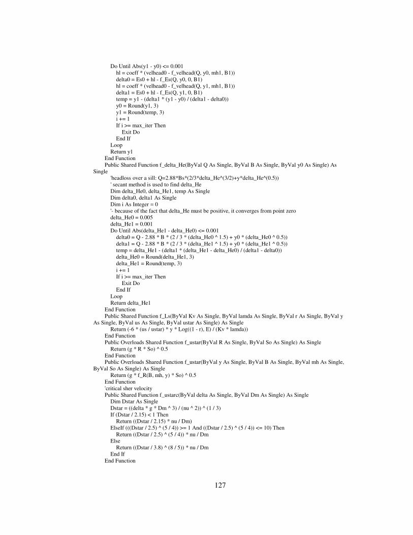
127
Do Until Abs(y1 - y0) <= 0.001 hl = coeff * (velhead0 - f_velhead(Q, y0, mh1, B1)) delta0 = Es0 + hl - f_Es(Q, y0, 0, B1) hl = coeff * (velhead0 - f_velhead(Q, y1, mh1, B1)) delta1 = Es0 + hl - f_Es(Q, y1, 0, B1) temp = y1 - (delta1 * (y1 - y0) / (delta1 - delta0)) y0 = Round(y1, 3) y1 = Round(temp, 3) i += 1 If i >= max_iter Then Exit Do End If Loop Return y1 End Function Public Shared Function f_delta_He(ByVal Q As Single, ByVal B As Single, ByVal y0 As Single) As Single 'headloss over a sill: Q=2.88*Bs*(2/3*delta_He^(3/2)+y*delta_He^(0.5)) ' secant method is used to find delta_He Dim delta_He0, delta_He1, temp As Single Dim delta0, delta1 As Single Dim i As Integer = 0 '- because of the fact that delta_He must be positive, it converges from point zero delta_He0 = 0.005 delta_He1 = 0.001 Do Until Abs(delta_He1 - delta_He0) <= 0.001 delta0 = Q - 2.88 * B * (2 / 3 * (delta_He0 ^ 1.5) + y0 * (delta_He0 ^ 0.5)) delta1 = Q - 2.88 * B * (2 / 3 * (delta_He1 ^ 1.5) + y0 * (delta_He1 ^ 0.5)) temp = delta_He1 - (delta1 * (delta_He1 - delta_He0) / (delta1 - delta0)) delta_He0 = Round(delta_He1, 3) delta_He1 = Round(temp, 3) i += 1 If i >= max_iter Then Exit Do End If Loop Return delta_He1 End Function Public Shared Function f_Ls(ByVal Kv As Single, ByVal lamda As Single, ByVal r As Single, ByVal y As Single, ByVal us As Single, ByVal ustar As Single) As Single Return (-6 * (us / ustar) * y * Log((1 - r), E) / (Kv * lamda)) End Function Public Overloads Shared Function f_ustar(ByVal R As Single, ByVal So As Single) As Single Return (g * R * So) ^ 0.5 End Function Public Overloads Shared Function f_ustar(ByVal y As Single, ByVal B As Single, ByVal mh As Single, ByVal So As Single) As Single Return (g * f_R(B, mh, y) * So) ^ 0.5 End Function 'critical sher velocity Public Shared Function f_ustarc(ByVal delta As Single, ByVal Dm As Single) As Single Dim Dstar As Single Dstar = ((delta * g * Dm ^ 3) / (nu ^ 2)) ^ (1 / 3) If (Dstar / 2.15) < 1 Then Return ((Dstar / 2.15) * nu / Dm) ElseIf (((Dstar / 2.5) ^ (5 / 4)) >= 1 And ((Dstar / 2.5) ^ (5 / 4)) <= 10) Then Return ((Dstar / 2.5) ^ (5 / 4)) * nu / Dm Else Return ((Dstar / 3.8) ^ (8 / 5)) * nu / Dm End If End Function

128
Public Shared Function f_beta(ByVal Wf As Single, ByVal Kv As Single, ByVal ustar As Single) As Single Return (Wf / (Kv * ustar)) End Function Public Overloads Shared Function f_lamda(ByVal beta As Single) As Single Return (8.87 * beta ^ 1.17) End Function Public Overloads Shared Function f_lamda(ByVal Wf As Single, ByVal Kv As Single, ByVal ustar As Single) As Single Return (8.87 * f_beta(Wf, Kv, ustar) ^ 1.17) End Function Public Shared Function f_Wf(ByVal Dm As Single) As Single Dim i As Integer = 0 Dim Wf_m(,) As Single = {{0.15 / 1000, 14.8 / 1000}, {0.3 / 1000, 36.1 / 1000}, {0.4 / 1000, 50 / 1000}, _ {0.5 / 1000, 64 / 1000}, {0.6 / 1000, 76.4 / 1000}, {0.8 / 1000, 99 / 1000}, {0.9 / 1000, 110 / 1000}, {1 / 1000, 121 / 1000}, _ {1.2 / 1000, 137.3 / 1000}, {1.5 / 1000, 166 / 1000}} If Dm < 0.00015 Then 'Dm<0.15 mm Return (663 * Dm ^ 2) ElseIf Dm > 0.0015 Then 'Dm>1.5 mm Return (134.5 * Dm ^ 0.5) Else Do Until (Wf_m(i, 0) >= Dm) i += 1 If i >= max_iter Then Exit Do End If Loop Return (Wf_m(i, 1) - (Wf_m(i, 0) - Dm) * (Wf_m(i, 1) - Wf_m(i - 1, 1)) / (Wf_m(i, 0) - Wf_m(i - 1, 0))) End If End Function Public Shared Function f_poly(ByVal F As Single, ByVal c0 As Single, ByVal p0 As Single, ByVal c1 As Single, ByVal p1 As Single, ByVal c2 As Single, ByVal p2 As Single, ByVal c3 As Single, ByVal p3 As Single, ByVal c4 As Single, ByVal p4 As Single) As Single() 'roots of a genereral polynomial function 'F(y)=c0*y^p0+c1*y^p1+c2*y^p2+c3*y^p3+c4*y^p4 'secant method is used to find the roots Dim yresult(1) As Single Dim y0, y1, temp As Single Dim delta0, delta1 As Single Dim i As Integer = 0 y0 = 1000 y1 = 990 Do Until Abs(y1 - y0) <= 0.001 delta0 = F - (c0 * (y0 ^ c0) + c1 * (y0 ^ c1) + c2 * (y0 ^ c2) + c3 * (y0 ^ c3) + c4 * (y0 ^ c4)) delta1 = F - (c0 * (y1 ^ c0) + c1 * (y1 ^ c1) + c2 * (y1 ^ c2) + c3 * (y1 ^ c3) + c4 * (y1 ^ c4)) temp = y1 - (delta1 * (y1 - y0) / (delta1 - delta0)) y0 = Round(y1, 3) y1 = Round(temp, 3) i += 1 If i >= max_iter Then Exit Do End If Loop yresult(0) = y1 'first root (subcritical depth) 'for the second alternate depth (second root of the equation) 'initialize the variables again i = 0 y0 = 0.01

129
y1 = 0.005 Do Until Abs(y1 - y0) <= 0.001 delta0 = F - (c0 * (y0 ^ c0) + c1 * (y0 ^ c1) + c2 * (y0 ^ c2) + c3 * (y0 ^ c3) + c4 * (y0 ^ c4)) delta1 = F - (c0 * (y1 ^ c0) + c1 * (y1 ^ c1) + c2 * (y1 ^ c2) + c3 * (y1 ^ c3) + c4 * (y1 ^ c4)) temp = y1 - (delta1 * (y1 - y0) / (delta1 - delta0)) y0 = Round(y1, 3) y1 = Round(temp, 3) i += 1 If i >= max_iter Then Exit Do End If Loop yresult(1) = y1 'second root (subcritical depth) Return yresult End Function Public Shared Function f_chocking_test(ByVal Q As Single, ByVal y0 As Single, ByVal mh As Single, ByVal B As Single) As Boolean If f_Es(Q, y0, mh, B) < f_Esmin(Q, B, mh) Then Return False Else Return True End If End Function Public Shared Function f_chocking_dz_max(ByVal Q As Single, ByVal y0 As Single, ByVal mh As Single, ByVal B As Single) As Single 'only an upward step causes discontinuity (no other section properties changes) 'in this case y1 becomes critical depth, because energy reduces to min energy Return (f_Es(Q, y0, mh, B) - f_Esmin(Q, B, mh)) End Function Public Shared Function f_chocking_B_min(ByVal Q As Single, ByVal mh As Single, ByVal y0 As Single, ByVal B As Single) As Single 'only bottom with decrease causes discontinuity (no other section properties changes) 'secant method is used to find B Dim E0 As Single = f_Es(Q, y0, mh, B) Dim B0, B1, temp As Single Dim delta0, delta1 As Single Dim i As Integer = 0 B0 = 0.01 B1 = 0.005 Do Until Abs(B1 - B0) <= 0.001 delta0 = E0 - f_Esmin(Q, B0, mh) delta1 = E0 - f_Esmin(Q, B1, mh) temp = B1 - (delta1 * (B1 - B0) / (delta1 - delta0)) B0 = Round(B1, 3) B1 = Round(temp, 3) i += 1 If i >= max_iter Then Exit Do End If Loop Return B1 End Function Delegate Function f_type1(ByVal arg1 As Single) As Single Delegate Function f_type2(ByVal arg1 As Single, ByVal arg2 As Single) As Single Delegate Function f_type3(ByVal arg1 As Single, ByVal arg2 As Single, ByVal arg3 As Single) As Single Delegate Function f_type4(ByVal arg1 As Single, ByVal arg2 As Single, ByVal arg3 As Single, ByVal arg4 As Single) As Single Delegate Function f_type5(ByVal arg1 As Single, ByVal arg2 As Single, ByVal arg3 As Single, ByVal arg4 As Single, ByVal arg5 As Single) As Single

130
Public Shared Function f_implicite_root(ByVal fconst As Single, ByVal f1 As f_type1, ByVal f2 As f_type2, ByVal f3 As f_type3, ByVal f4 As f_type4, ByVal f5 As f_type5, ByVal c1 As Single, ByVal c2 As Single, ByVal c3 As Single, ByVal c4 As Single, ByVal c5 As Single, ByVal uargno2 As Byte, ByVal uargno3 As Byte, ByVal uargno4 As Byte, ByVal uargno5 As Byte, ByVal ParamArray args() As Single) As Single '*********************************************************************************** '* EXPLANATION: Implicite function solver by taking function arguments * '* Argument types are function because of flexibility in use of the * '* function (in order to make function as a general solver) * '* NOTES: in order to use functions as arguments "Delegates(function pointers)" were used. * '* 5 types of functions were used; f_type1, f_type2,..... * '* In delegate names, f_typeX; X indicares the no.of arguments of the func. * '* Paramarray args(); are for the arguments of the delegates used in function * '* "uargno" are for the unkown parameter which is to be found.In order to * '* know where the unknown parameter is placed as the argument of the original * '* function, this argument was used.It is the place of the unknown parameter * '* in the original function's argument list. * '*********************************************************************************** 'Secant method is used to iterate the depth. Dim y0, y1, temp As Single Dim delta0, delta1 As Single Dim i As Integer = 0 y0 = 1000 y1 = 990 Do Until Abs(y1 - y0) <= 0.001 delta0 = fconst delta1 = fconst If c1 <> 0 Then delta0 += c1 * f1.Invoke(y0) delta1 += c1 * f1.Invoke(y1) End If If c2 <> 0 Then Select Case uargno2 Case 1 delta0 += c2 * f2.Invoke(y0, args(0)) delta1 += c2 * f2.Invoke(y1, args(0)) Case 2 delta0 += c2 * f2.Invoke(args(0), y0) delta1 += c2 * f2.Invoke(args(0), y1) End Select End If If c3 <> 0 Then Select Case uargno3 Case 1 delta0 += c3 * f3.Invoke(y0, args(1), args(2)) delta1 += c3 * f3.Invoke(y1, args(1), args(2)) Case 2 delta0 += c3 * f3.Invoke(args(1), y0, args(2)) delta1 += c3 * f3.Invoke(args(1), y1, args(2)) Case 3 delta0 += c3 * f3.Invoke(args(1), args(2), y0) delta1 += c3 * f3.Invoke(args(1), args(2), y1) End Select End If If c4 <> 0 Then Select Case uargno4 Case 1 delta0 += c4 * f4.Invoke(y0, args(3), args(4), args(5)) delta1 += c4 * f4.Invoke(y1, args(3), args(4), args(5))

131
Case 2 delta0 += c4 * f4.Invoke(args(3), y0, args(4), args(5)) delta1 += c4 * f4.Invoke(args(3), y1, args(4), args(5)) Case 3 delta0 += c4 * f4.Invoke(args(3), args(4), y0, args(5)) delta1 += c4 * f4.Invoke(args(3), args(4), y1, args(5)) Case 4 delta0 += c4 * f4.Invoke(args(3), args(4), args(5), y0) delta1 += c4 * f4.Invoke(args(3), args(4), args(5), y1) End Select End If If c5 <> 0 Then Select Case uargno5 Case 1 delta0 += c5 * f5.Invoke(y0, args(6), args(7), args(8), args(9)) delta1 += c5 * f5.Invoke(y1, args(6), args(7), args(8), args(9)) Case 2 delta0 += c5 * f5.Invoke(args(6), y0, args(7), args(8), args(9)) delta1 += c5 * f5.Invoke(args(6), y1, args(7), args(8), args(9)) Case 3 delta0 += c5 * f5.Invoke(args(6), args(7), y0, args(8), args(9)) delta1 += c5 * f5.Invoke(args(6), args(7), y1, args(8), args(9)) Case 4 delta0 += c5 * f5.Invoke(args(6), args(7), args(8), y0, args(9)) delta1 += c5 * f5.Invoke(args(6), args(7), args(8), y1, args(9)) Case 5 delta0 += c5 * f5.Invoke(args(6), args(7), args(8), args(9), y0) delta1 += c5 * f5.Invoke(args(6), args(7), args(8), args(9), y1) End Select End If temp = y1 - (delta1 * (y1 - y0) / (delta1 - delta0)) y0 = Round(y1, 3) y1 = Round(temp, 3) i += 1 If i >= max_iter Then Exit Do End If Loop Return y1 End Function '********************************************************************************* '* SPILLWAY HYDRAULICS FUNCTIONS * '********************************************************************************* Public Overloads Shared Function f_Co(ByVal P As Single, ByVal Ho As Single) As Single Dim x As Single = P / Ho If (x < 2.8) Then Return (-0.0201 * (x ^ 6) + 0.2148 * (x ^ 5) - 0.915 * (x ^ 4) + 1.982 * (x ^ 3) - 2.3081 * (x ^ 2) + 1.414 * (x) + 1.7719) Else Return 2.18 End If End Function Public Overloads Shared Function f_Co(ByVal P_over_Ho As Single) As Single Dim x As Single = P_over_Ho If (x < 2.8) Then Return (-0.0201 * (x ^ 6) + 0.2148 * (x ^ 5) - 0.915 * (x ^ 4) + 1.982 * (x ^ 3) - 2.3081 * (x ^ 2) + 1.414 * (x) + 1.7719) Else Return 2.18 End If

132
End Function Public Overloads Shared Function f_CincCo(ByVal P_over_Ho As Single, ByVal alfa As Single) As Single 'alfa in degrees Dim x As Single = P_over_Ho If alfa = 0 Then Return 1 ElseIf alfa = 18 Then Return (1.01 - 0.02 * x + 0.01 * (x ^ 2) - 0.004 * (x ^ 3)) ElseIf alfa = 33 Then Return (1.04 - 0.06 * x + 0.04 * (x ^ 2) - 0.01 * (x ^ 3)) ElseIf alfa = 45 Then Return (1.06 - 0.13 * x + 0.1 * (x ^ 2) - 0.03 * (x ^ 3)) 'should be revised; maybe it is not true to make interpolation or extrapolation ElseIf alfa > 0 And alfa < 18 Then Return (f_CincCo(x, 18) - (f_CincCo(x, 33) - f_CincCo(x, 18)) / (33 - 18) * (18 - alfa)) ElseIf (alfa > 18 And alfa < 33) Then Return (f_CincCo(x, 18) + (f_CincCo(x, 33) - f_CincCo(x, 18)) / (33 - 18) * (alfa - 18)) ElseIf alfa > 33 And alfa < 45 Then Return (f_CincCo(x, 33) + (f_CincCo(x, 45) - f_CincCo(x, 33)) / (45 - 33) * (alfa - 33)) ElseIf alfa > 45 Then Return (f_CincCo(x, 45) + (f_CincCo(x, 45) - f_CincCo(x, 33)) / (45 - 33) * (alfa - 45)) End If End Function Public Overloads Shared Function f_CincCo(ByVal P As Single, ByVal Ho As Single, ByVal alfa As Single) As Single 'alfa in degrees Dim x As Single = P / Ho If alfa = 0 Then Return 1 ElseIf alfa = 18 Then Return (1.01 - 0.02 * x + 0.01 * (x ^ 2) - 0.004 * (x ^ 3)) ElseIf alfa = 33 Then Return (1.04 - 0.06 * x + 0.04 * (x ^ 2) - 0.01 * (x ^ 3)) ElseIf alfa = 45 Then Return (1.06 - 0.13 * x + 0.1 * (x ^ 2) - 0.03 * (x ^ 3)) 'should be revised; maybe it is not true to make interpolation or extrapolation ElseIf alfa > 0 And alfa < 18 Then Return (f_CincCo(x, 18) - (f_CincCo(x, 33) - f_CincCo(x, 18)) / (33 - 18) * (18 - alfa)) ElseIf (alfa > 18 And alfa < 33) Then Return (f_CincCo(x, 18) + (f_CincCo(x, 33) - f_CincCo(x, 18)) / (33 - 18) * (alfa - 18)) ElseIf alfa > 33 And alfa < 45 Then Return (f_CincCo(x, 33) + (f_CincCo(x, 45) - f_CincCo(x, 33)) / (45 - 33) * (alfa - 33)) ElseIf alfa > 45 Then Return (f_CincCo(x, 45) + (f_CincCo(x, 45) - f_CincCo(x, 33)) / (45 - 33) * (alfa - 45)) End If End Function Public Shared Function f_CmeCo(ByVal He As Single, ByVal Ho As Single) As Single Dim x As Single = He / Ho Return (0.03 * (x ^ 3) - 0.14 * (x ^ 2) + 0.32 * (x) + 0.79) End Function Public Shared Function f_CmaCo(ByVal hd As Single, ByVal d As Single, ByVal He As Single) As Single Dim x As Single = (hd + d) / He If (x <= 1.7) Then Return (-30.015 * (x ^ 6) + 246.11 * (x ^ 5) - 836.08 * (x ^ 4) + 1506.7 * (x ^ 3) - 1520.1 * (x ^ 2) + 815.14 * (x) - 180.98) Else Return 1 End If End Function

133
Public Shared Function f_CmsCo(ByVal hd As Single, ByVal He As Single) As Single Dim x As Single = hd / He If (x < 0.7) Then Return (-161.95 * (x ^ 6) + 416.35 * (x ^ 5) - 426.22 * (x ^ 4) + 224.51 * (x ^ 3) - 66.258 * (x ^ 2) + 11.212 * (x) + 0.0242) Else Return 1.0 End If End Function Public Shared Function f_Cgate(ByVal d As Single, ByVal H1 As Single) As Single Dim x As Single = d / H1 Return (-13.168 * (x ^ 6) + 29.721 * (x ^ 5) - 25.295 * (x ^ 4) + 9.8034 * (x ^ 3) - 1.5358 * (x ^ 2) - 0.0995 * (x) + 0.7341) End Function Public Overloads Shared Function f_Kp(ByVal description As String) As Single If description = "square" Then Return 0.02 ElseIf description = "rounded" Then Return 0.01 Else Return 0 End If End Function Public Overloads Shared Function f_Kp(ByVal type As Byte) As Single If type = 1 Then 'x=1; square Return 0.02 ElseIf type = 2 Then 'x=2; rounded Return 0.01 Else 'x=3; pointed Return 0 End If End Function Public Overloads Shared Function f_Ka(ByVal description As String) As Single If description = "square" Then Return 0.2 ElseIf description = "rounded" Then Return 0.1 Else Return 0 End If End Function Public Overloads Shared Function f_Ka(ByVal type As Byte) As Single If type = 1 Then Return 0.2 ElseIf type = 2 Then Return 0.1 Else Return 0 End If End Function 'better function, H is needed for check Public Overloads Shared Function f_Qsplw(ByVal Ct As Single, ByVal L As Single, ByVal Ho As Single, ByVal H As Single) As Single 'no gated (or gates are fully open) overflow type spillway; 'for this type the total effects are considered . If (H >= 0 And L >= 0) Then Return Ct * L * Ho ^ (3 / 2) Else Return 0 End If End Function

134
'have some problem, Ho maybe greater but, H may be lower; therefore above func is better, because of the fact that the H is the real criteria to be considered. Public Overloads Shared Function f_Qsplw(ByVal Ct As Single, ByVal L As Single, ByVal Ho As Single) As Single 'no gated (or gates are fully open) overflow type spillway; 'for this type the total effects are considered . If (Ho >= 0 And L >= 0) Then Return Ct * L * Ho ^ (3 / 2) Else Return 0 End If End Function Public Shared Function f_Qsplw_g(ByVal C As Single, ByVal H1 As Single, ByVal d As Single, ByVal L As Single) As Single 'gated overflow spillway; only gate constant C is considered, ' but gates are fully open, it is a non-gated overflow spillway Dim H2 As Single = H1 - d Return 2 / 3 * ((2 * g) ^ 0.5) * C * L * (H1 ^ 1.5 - H2 ^ 1.5) End Function Public Shared Function f_Qslcw(ByVal C As Single, ByVal A As Single, ByVal h As Single) As Single If (h >= 0 And A >= 0) Then Return (C * A * (2 * g * h) ^ 0.5) Else Return 0 End If End Function 'stilling basin type calculation Public Shared Function f_sbtype(ByVal y1 As Single, ByVal y2 As Single, ByVal y3 As Single, ByVal Q As Single, ByVal B As Single) As stillingbasin Dim result As New stillingbasin() Dim u1 As Single Dim Fr1 As Single Dim H3, H4 As Single u1 = f_u(Q, y1, 0, B) Fr1 = f_Fr(Q, y1, 0, B) H3 = (y1 * (4 + Fr1)) / 6 H4 = (y1 * (9 + Fr1)) / 9 'these are common for all type result.y1 = y1 result.y2 = y2 result.y3 = y3 result.u1 = u1 result.Fr1 = Fr1 result.B = B If (y2 = y3) Then result.type = "I" result.L = y1 * (-0.1521 * Fr1 ^ 2 + 11.487 * Fr1 - 12.107) result.n_baffle_piers = 0 result.vol_baffle_piers = 0 result.n_chute_blocks = 0 result.vol_chute_blocks = 0 ElseIf (y2 > y3) Then If (Round(Fr1, 1) >= 4.5 And Round(u1, 0) >= 15) Then result.type = "II" result.L = 4.3 * y2 result.TW = 0.97 * y2 result.delta_usbr = 0.2 * y2 result.delta = f_Es(Q, y2, 0, B) - f_Es(Q, y3, 0, B) result.n_baffle_piers = 0 result.vol_baffle_piers = 0

135
result.n_chute_blocks = CInt(B / (2 * y1)) result.vol_chute_blocks = result.n_chute_blocks * (y1 ^ 3) / 2 ElseIf (Round(Fr1, 1) >= 4.5 And Round(u1, 0) < 15) Then result.type = "III" result.L = 2.7 * y2 result.TW = 0.83 * y2 result.delta_usbr = H4 result.delta = f_Es(Q, y2, 0, B) - f_Es(Q, y3, 0, B) result.n_baffle_piers = CInt(B / (1.5 * H3)) result.vol_baffle_piers = result.n_baffle_piers * (0.7 * H3 * 0.75 * H3) result.n_chute_blocks = CInt(B / (2 * y1)) result.vol_chute_blocks = result.n_chute_blocks * (y1 ^ 3) / 2 ElseIf (Round(Fr1, 1) >= 2.5 And Round(Fr1, 0) < 4.5) Then result.type = "IV" result.L = 6.1 * y2 result.TW = y2 result.delta_usbr = H4 result.delta = f_Es(Q, y2, 0, B) - f_Es(Q, y3, 0, B) result.n_baffle_piers = 0 result.vol_baffle_piers = 0 result.n_chute_blocks = CInt(B / (3.5 * y1)) result.vol_chute_blocks = result.n_chute_blocks * (4 * y1 ^ 3) / 2 Else result.type = "NA" result.L = 0 result.TW = 0 result.delta_usbr = 0 result.delta = 0 result.n_baffle_piers = 0 result.vol_baffle_piers = 0 result.n_chute_blocks = 0 result.vol_chute_blocks = 0 End If ElseIf (y2 < y3) Then result.type = "V" result.L = 0 result.TW = 0 result.delta_usbr = 0 result.delta = 0 result.n_baffle_piers = 0 result.vol_baffle_piers = 0 result.n_chute_blocks = 0 result.vol_chute_blocks = 0 End If Return result End Function 'seepage analysis (Lane's creep analysis) functions Public Shared Function f_Lcreep(ByVal crpath() As c_point) As Single 'crpath:creep_path Dim i As Integer Dim alfa As Single Dim Lcr As Single = 0 ' creep length For i = 0 To (crpath.GetUpperBound(0) - 1) 'last point is boundary (not a length) 'alfa in degrees alfa = Abs(Atan((crpath(i + 1).y - crpath(i).y) / (crpath(i + 1).x - crpath(i).x)) * 360 / (2 * PI)) If alfa >= 45 Then 'vertical Lcr = Lcr + Abs(crpath(i + 1).y - crpath(i).y) Else 'horizantal Lcr = Lcr + Abs(crpath(i + 1).x - crpath(i).x) / 3 End If Next

136
Return Lcr End Function 'Darcy_Weissbach friction coeff. functions Public Shared Function f_f_roughp(ByVal Dp As Single, ByVal ks As Single) As Single Dim r As Single = Dp / 2 Return (1 / (2 * Log10(r / ks) + 1.75)) ^ 2 End Function #Region "Polynomial calculations" Public Shared Function f_poly_A(ByVal points() As c_point) As Single 'Assume that the last point is connected to the first point (there is need to define the first point as the last point again) 'this function may return area + or - acc to the direction used 'area is + in ccw, - in cw directions. ' + or - value is needed for centroid calculations therefore another function taking the absolute was defined Dim i As Integer Dim area As Single = 0 For i = 0 To points.GetUpperBound(0) - 1 area = area + (points(i).x * points(i + 1).y - points(i + 1).x * points(i).y) Next area = area / 2 Return area End Function Public Shared Function f_poly_area(ByVal points() As c_point) As Single 'this function returns the abs area of polygon Return Abs(f_poly_A(points)) End Function Public Shared Function f_poly_centr(ByVal points() As c_point) As c_point 'Asssume that the points of the polygon are arranged in clockwise 'Assume that the last point is connected to the first point (no need to define the first point twice) Dim i As Integer Dim centr As New c_point(0, 0) Dim A As Single A = f_poly_A(points) For i = 0 To points.GetUpperBound(0) - 1 centr.x = centr.x + (points(i).x + points(i + 1).x) * (points(i).x * points(i + 1).y - points(i + 1).x * points(i).y) centr.y = centr.y + (points(i).y + points(i + 1).y) * (points(i).x * points(i + 1).y - points(i + 1).x * points(i).y) Next centr.x = centr.x / (6 * A) centr.y = centr.y / (6 * A) Return centr End Function #End Region Public Shared Function f_trap_centr_d_from_l(ByVal b As Single, ByVal a As Single) As Single 'typical trapezoid cenroid with a smaller width whereas b greater width 'l is the vertical length of trap Return (a ^ 2 + b ^ 2 + a * b) / (3 * (a + b)) End Function Public Shared Function f_trap_centr_d_from_b(ByVal b As Single, ByVal a As Single, ByVal l As Single) As Single 'typical trapezoid cenroid with a smaller width whereas b greater width Return (l * (2 * a + b)) / (3 * (a + b)) End Function 'for computation messages Public Shared Function f_comp_inf(ByVal percent As Single, ByVal message As String, ByVal state As Byte) As computation_information Dim result As New computation_information() result.percent = percent

137
result.message = message result.state = state Return result End Function End Class <Serializable()> Public Class xsec_hyd '*********************************************************************************** '* CLASS DECLERATION: X-SECTIONAL HYDRAULIC CALCULATIONS * '*********************************************************************************** '* EXPLANATION: 3 types of problem can be solved * '* Each type is explained in "Construction Region" of the class. * '* Each constructor corresponds to 1 type of problem. * '*********************************************************************************** '* GIVEN : acc.to the type of problem, it changes (look at "Constructor Region") * '*********************************************************************************** '* OUTPUT: All hydraulic characteristic of that cross-section. * '*********************************************************************************** '* WRITTEN BY: KAMIL HAKAN TURAN * '* DATE:13.08.2003 * '*********************************************************************************** #Region "Private variables: (class core)" Private prb_type As Byte 'to indicate the type of problem Private y As Single 'normal depth as section) Private B As Single Private mh As Single Private n As Single Private A As Single Private P As Single Private T As Single Private Dy As Single Private R As Single Private Sf As Single Private Q As Single Private u As Single Private vel_head As Single Private Hgl As Single Private Egl As Single Private ycritical As Single Private Fr As Single Private flow As String Private Kb As Single 'bottom elevation of x-section(ground elevation) Private Sfc As Single Private Es As Single Private Esmin As Single Private km_xsec As Single 'horizantal cross section km (for functionality of other computations) Private tslab As Single 'slab thickness for concrete volume comp Private twall As Single 'wall thickness for concrete volume comp #End Region #Region "class interface" Private Sub compute() Select Case prb_type Case 1 Q = f_Qmann(B, mh, y, n, Sf) Case 2 y = f_ynormal(Q, B, mh, n, Sf) Case 3 Sf = f_Sf(Q, y, B, mh, n) End Select T = f_T(B, mh, y) A = f_A(B, mh, y) P = f_P(B, mh, y)

138
R = A / P Dy = A / T u = f_u(Q, A) vel_head = f_velhead(u) Fr = f_Fr(u, Dy) flow = f_flow(Fr) ycritical = f_ycritical(Q, B, mh) Es = f_Es(Q, y, u) Esmin = f_Esmin(Q, B, mh) Hgl = f_HGL(Kb, y) Egl = f_EGL(Kb, u, y) Sfc = f_Sfc(Q, B, mh, n) End Sub #End Region #Region "Poperties section: " '"_p" hold for the word "Property"; read and write allowed '"_pro" hold for the word "Property"; Read Only....pro '"_pwo" hold for the word "Property"; Write Only...pwo Public Property tslab_p() As Single Set(ByVal Value As Single) tslab = Value End Set Get Return tslab End Get End Property Public Property twall_p() As Single Set(ByVal Value As Single) twall = Value End Set Get Return twall End Get End Property Public Property km_xsec_p() As Single Set(ByVal Value As Single) km_xsec = Value End Set Get Return km_xsec End Get End Property Public ReadOnly Property prb_type_pro() As Byte Get Return prb_type End Get End Property Public ReadOnly Property y_pro() As Single Get Return y End Get End Property Public ReadOnly Property B_pro() As Single Get Return B End Get End Property Public ReadOnly Property mh_pro() As Single Get Return mh End Get

139
End Property Public ReadOnly Property n_pro() As Single Get Return n End Get End Property Public ReadOnly Property A_pro() As Single Get Return A End Get End Property Public ReadOnly Property P_pro() As Single Get Return P End Get End Property 'not important for hydraulics, only to determine canal structure 'freeboard Public ReadOnly Property f_pro() As Single Get Return 0.2 * (1 + y) End Get End Property 'canal top elevation Public ReadOnly Property Kt_pro() As Single Get Return (f_pro + y + Kb) End Get End Property 'canal height Public ReadOnly Property z_pro() As Single Get Return (Kt_pro - Kb_pro) End Get End Property Public ReadOnly Property T_pro() As Single Get Return T End Get End Property Public ReadOnly Property Dy_pro() As Single Get Return Dy End Get End Property Public ReadOnly Property R_pro() As Single Get Return R End Get End Property Public ReadOnly Property Sf_pro() As Single Get Return Sf End Get End Property Public ReadOnly Property Q_pro() As Single Get Return Q End Get End Property Public ReadOnly Property u_pro() As Single
140
Get Return u End Get End Property Public ReadOnly Property vel_head_pro() As Single Get Return vel_head End Get End Property Public ReadOnly Property Hgl_pro() As Single Get Return Hgl End Get End Property Public ReadOnly Property Egl_pro() As Single Get Return Egl End Get End Property Public ReadOnly Property ycritical_pro() As Single Get Return ycritical End Get End Property ' Public ReadOnly Property Fr_pro() As Single Get Return Fr End Get End Property Public ReadOnly Property flow_pro() As String Get Return flow End Get End Property Public ReadOnly Property Kb_pro() As Single Get Return Kb End Get End Property Public ReadOnly Property Sfc_pro() As Single Get Return Sfc End Get End Property Public ReadOnly Property Es_pro() As Single Get Return Es End Get End Property Public ReadOnly Property Esmin_pro() As Single Get Return Esmin End Get End Property Public ReadOnly Property Aconc_sides_pro() As Single 'concrete area Get Return (Sqrt(1 + mh ^ 2) * z_pro * 2 * twall) End Get End Property Public ReadOnly Property Aconc_slab_pro() As Single 'concrete area

141
Get Return B * tslab End Get End Property Public ReadOnly Property Aconc_tot_pro() As Single 'concrete area Get Return (Sqrt(1 + mh ^ 2) * z_pro * 2 * twall) + B * tslab End Get End Property #End Region #Region "Constructor section:" 'copy constructor Public Sub New(ByVal inp As xsec_hyd) Me.A = inp.A Me.B = inp.B Me.Dy = inp.Dy Me.Egl = inp.Egl Me.Es = inp.Es Me.Esmin = inp.Esmin Me.flow = inp.flow Me.Fr = inp.Fr Me.Hgl = inp.Hgl Me.Kb = inp.Kb Me.km_xsec = inp.km_xsec Me.mh = inp.mh Me.n = inp.n Me.P = inp.P Me.prb_type = inp.prb_type Me.Q = inp.Q Me.R = inp.R Me.Sf = inp.Sf Me.Sfc = inp.Sfc Me.T = inp.T Me.tslab = inp.tslab Me.twall = inp.twall Me.u = inp.u Me.vel_head = inp.vel_head Me.y = inp.y Me.ycritical = inp.ycritical End Sub Public Sub New(ByVal water_depth As Double, ByVal horizantal_inclination As Double, ByVal bottom_width As Double, ByVal manning_n As Double, ByVal friction_slope As Double, Optional ByVal bottom_elevation As Double = 0.0, Optional ByVal xsection_km As Double = 0.0, Optional ByVal inp_tslab As Double = 0, Optional ByVal inp_twall As Double = 0) '********************************************************** '* PROBLEM TYPE-1 : MANNING DISCHARGE CALCULATION * '* GIVEN: xsection data,normal depth * '* OUTPUT: Q: Manning discharge * '********************************************************** prb_type = 1 y = water_depth mh = horizantal_inclination B = bottom_width n = manning_n Sf = friction_slope Kb = bottom_elevation km_xsec = xsection_km tslab = inp_tslab twall = inp_twall Me.compute() End Sub

142
Public Sub New(ByVal discharge As Double, ByVal horizantal_inclination As Double, ByVal bottom_width As Double, ByVal manning_n As Double, ByVal friction_slope As Double, ByVal description1 As Boolean, Optional ByVal bottom_elevation As Double = 0.0, Optional ByVal xsection_km As Double = 0.0, Optional ByVal inp_tslab As Double = 0, Optional ByVal inp_twall As Double = 0) ''****************************************************** '* PROBLEM TYPE-2 : NORMAL DEPTH CALCULATION * '* GIVEN: x-section data, discharge * '* OUTPUT: y: normal depth * '****************************************************** prb_type = 2 Q = discharge mh = horizantal_inclination B = bottom_width n = manning_n Sf = friction_slope Kb = bottom_elevation km_xsec = xsection_km tslab = inp_tslab twall = inp_twall Me.compute() End Sub Public Sub New(ByVal discharge As Double, ByVal water_depth As Double, ByVal horizantal_inclination As Double, ByVal bottom_width As Double, ByVal manning_n As Double, ByVal description1 As Boolean, ByVal description2 As Boolean, Optional ByVal bottom_elevation As Double = 0.0, Optional ByVal xsection_km As Double = 0.0, Optional ByVal inp_tslab As Double = 0, Optional ByVal inp_twall As Double = 0) ''****************************************************** '* PROBLEM TYPE-3 : FRICTION SLOPE CALCULATION * '* GIVEN: x-section data, discharge,normal depth * '* OUTPUT: Sf: friction slope * '****************************************************** prb_type = 3 Q = discharge y = water_depth mh = horizantal_inclination B = bottom_width n = manning_n Kb = bottom_elevation km_xsec = xsection_km tslab = inp_tslab twall = inp_twall Me.compute() End Sub #End Region End Class <Serializable()> Public Class ws_profile 'this class is only for trapezoidal type prismatic channels (bed elev and xsec constant) 'for the time being it is only for subcritical flows (mild slope); calculation; from d/s to u/s Public Shared max_iter_sstep As Integer = 500 Public Shared max_iter_wsp_ynormal As Integer = 500 Public Shared max_iter_wsp_Lx As Integer = 500 #Region "Private variables" 'input and output Private xsec(0) As xsec_hyd 'initially 1 xsec, in need it will be increased dynamically (redim) Private err(0) As Single Private H2a As Single 'second xsec head (1st eqn) Private H2b As Single 'second xsec head (2nd eqn) Private dx As Single Private Lx As Single Private y_start As Single

143
Private y_end As Single Private prb_type2 As Boolean Private Lx_end As Single Private y_end_comp As Single Private So As Single 'channel bed slope const, req to find the elev of new xsec Private Sf_ave As Single 'average friction slope btw sections 'in order to use this function in other class it was declared as public Public Shared Function f_dy2(ByVal inp_err As Single, ByVal inp_dx As Single, ByVal inp_Fr2 As Single, ByVal inp_Sf2 As Single, ByVal inp_R2 As Single) As Single Return (inp_err / (1 - inp_Fr2 ^ 2 + 3 * inp_Sf2 * inp_dx / (2 * inp_R2))) End Function Private Sub calculate_y2(ByVal i As Integer) Dim y_assumed As Single Dim dy2 As Single Dim iter As Integer = 0 'a big assumed value,from d/s to u/s y2 will be greater than the preceding y_assumed = xsec(i).y_pro + 10 err(i) = 1000 'initially big value Do Until (Abs(err(i)) <= 0.0001) xsec(i + 1) = New xsec_hyd(xsec(0).Q_pro, y_assumed, xsec(0).mh_pro, xsec(0).B_pro, xsec(0).n_pro, True, True, xsec(i).Kb_pro + So * dx, xsec(i).km_xsec_p - dx) H2a = xsec(i + 1).Egl_pro Sf_ave = (xsec(i).Sf_pro + xsec(i + 1).Sf_pro) / 2 H2b = xsec(i).Egl_pro + Sf_ave * dx err(i) = H2a - H2b dy2 = f_dy2(err(i), dx, xsec(i + 1).Fr_pro, xsec(i + 1).Sf_pro, xsec(i + 1).R_pro) y_assumed -= dy2 iter += 1 If iter >= max_iter_sstep Then Exit Do End If Loop End Sub #End Region #Region "Class interface" Private Sub compute() Dim i As Integer 'check the input (the program works for subcritical regime ) If (xsec(0).flow_pro <> "supercritical") Then If prb_type2 = False Then If (y_end > xsec(0).y_pro) Then i = 0 Lx = 0 Do Until (Round(xsec(i).y_pro, 3) >= Round(y_end, 3)) ReDim Preserve xsec(xsec.GetUpperBound(0) + 1) ReDim Preserve err(xsec.GetUpperBound(0)) calculate_y2(i) Lx += dx i += 1 If i >= max_iter_wsp_ynormal Then Exit Do End If Loop y_end_comp = xsec(i).y_pro Else i = 0 Lx = 0 Do Until (Round(xsec(i).y_pro, 3) <= Round(y_end, 3)) ReDim Preserve xsec(xsec.GetUpperBound(0) + 1) ReDim Preserve err(xsec.GetUpperBound(0)) calculate_y2(i)

144
Lx += dx i += 1 If i >= max_iter_wsp_ynormal Then Exit Do End If Loop y_end_comp = xsec(i).y_pro End If Else Lx = 0 Do Until (Lx >= Lx_end) ReDim Preserve xsec(xsec.GetUpperBound(0) + 1) ReDim Preserve err(xsec.GetUpperBound(0)) calculate_y2(i) Lx += dx i += 1 If i >= max_iter_wsp_Lx Then Exit Do End If Loop y_end_comp = xsec(i).y_pro End If End If End Sub #End Region #Region "Properties" Public ReadOnly Property xsec_pro() As xsec_hyd() Get Return xsec End Get End Property Public ReadOnly Property err_pro() As Single() Get Return err End Get End Property Public ReadOnly Property y_end_comp_pro() As Single Get Return y_end_comp End Get End Property Public ReadOnly Property Lx_pro() As Single Get Return Lx End Get End Property #End Region #Region "Constructors" Public Sub New(ByVal inp_Q As Single, ByVal inp_n As Single, ByVal inp_B As Single, ByVal inp_So As Single, ByVal inp_Kb As Single, ByVal inp_mh As Single, ByVal inp_y_start As Single, ByVal inp_y_end As Single, ByVal inp_dx As Single) 'computation is made for a boundary depth; therefore Lx(length when this depth occurs) calculated xsec(0) = New xsec_hyd(inp_Q, inp_y_start, inp_mh, inp_B, inp_n, True, True, inp_Kb, 0) y_start = inp_y_start y_end = inp_y_end So = inp_So dx = inp_dx prb_type2 = False Me.compute() End Sub

145
Public Sub New(ByVal inp_Q As Single, ByVal inp_n As Single, ByVal inp_B As Single, ByVal inp_So As Single, ByVal inp_Kb As Single, ByVal inp_mh As Single, ByVal inp_y_start As Single, ByVal inp_Lx_end As Single, ByVal inp_dx As Single, ByVal inp_Lx_type As Boolean) 'prb_type is only for making overloading 'computation is made for a a determined length ; therefore y(wdepth) at that length loc is calculated. xsec(0) = New xsec_hyd(inp_Q, inp_y_start, inp_mh, inp_B, inp_n, True, True, inp_Kb, 0) y_start = inp_y_start So = inp_So dx = inp_dx Lx_end = inp_Lx_end prb_type2 = True Me.compute() End Sub #End Region End Class #End Region End Namespace Namespace intake_design #Region "data structures" <Serializable()> Public Class intake_input_data Public Qi As Single ': irrigation discharge Public Bop As Single ': optimum bottom width of main irrigation canal Public So As Single ': bottom slope of main irrigation canal Public mh As Single ': vertical slope of side of trapezoidal canal (main irrigation canal) Public n As Single ': Manning's roughness coeff.for lined canals (main irrigation canal and intake structure) Public K0 As Single ': bottom elevation at the beginning of the main irrigation canal Public B1 As Single ': bottom width at section-1 (rect.intake canal) B1~2*Bop Public B1_inc As Single ': increment value for B1 Public t As Single ': thickness of piers at section-2 Public np As Integer ': no of piers at section-2 Public Bs As Single ': channel width at section-3 Public Bs_inc As Single ': Bs increment value Public Sd As Single ': Settling basin slope Public Dm As Single ': min size of sediment to be settled in settling basin Public r As Single ': sediment removal ratio Public np2 As Integer ': no of piers at section-7 (entrance of the intake) Public t2 As Single ': thickness of piers at section-7 (entrance of the intake) Public t_tr As Single ': thickness of rackbars at the entrance of intake Public n_tr As Integer ': number of rackbars Public Dfo As Single ': max. diameter of floating objects to be allowed to enter the intake Public dsu As Single ': upward sill height (at section-4) Public dsu_max As Single ': max.allowable value for upward sill height (at section-4) Public dsu_inc As Single ': increment value for calculating upward sill height (at section-4) Public Ls As Single ': length of settling basin Public Ls_inc As Single ': increment value for calculation of Ls Public dsd As Single ': downward step height at section-6 Public dsd_inc As Single ': increment value for calculation of downward step height Public du_min As Single ': min.allowable height for upward step (infront of intake) Public du_max As Single ': max.allowable height for upward step (infront of intake) Public dHes As Single ': minorloss above dsd (default=0.02) Public Cc As Single ': headloss coeff through the curvature (default~0.2) Public Cyc As Single ': coeff of critical depth at section-1 in order to calculate limitation (default=1.1) Public Ct As Single ': headloss coeff. through the transition btw section-0 and section-1 (default=0.3 for straight transition) Public K As Single ': headloss coeff.through the gate (orifice constant) (at section-3 to section-4 and at entrance of intake) Public Kv As Single ': the Von Korman constant for calculation of Ls (settling basin length) Public u4_max As Single ': max allowable velocity for settlement of sediment at section-5

146
Public delta_Kwi As Single ': Kwi increment for calculating Ks in order to calculate crest elev. of spillway Public Kst As Single ': min.channel elev at the most u/s section (section where spillway is constructed) Public hl_add As Single ': any additional headloss value for calculation flexibility of different problems 'no need for hydraulic computations but needed for km_xsec Public L12 As Single ': dist betw sect-1 and sect-2 Public Lc As Single ': length of curvature Public Lentr As Single ': length at the entrance of intake (computed from creep lengths; no additional input) Public Sub New(ByVal inp As intake_input_data) With Me .B1 = inp.B1 .B1_inc = inp.B1_inc .Bop = inp.Bop .Bs = inp.Bs .Bs_inc = inp.Bs_inc .Cc = inp.Cc .Ct = inp.Ct .Cyc = inp.Cyc .delta_Kwi = inp.delta_Kwi .Dfo = inp.Dfo .dHes = inp.dHes .Dm = inp.Dm .dsd = inp.dsd .dsd_inc = inp.dsd_inc .dsu = inp.dsu .dsu_inc = inp.dsu_inc .dsu_max = inp.dsu_max .du_max = inp.du_max .du_min = inp.du_min .hl_add = inp.hl_add .K = inp.K .K0 = inp.K0 .Kst = inp.Kst .Kv = inp.Kv .L12 = inp.L12 .Lc = inp.Lc .Lentr = inp.Lentr .Ls = inp.Ls .Ls_inc = inp.Ls_inc .mh = inp.mh .n = inp.n .n_tr = inp.n_tr .np = inp.np .np2 = inp.np2 .Qi = inp.Qi .r = inp.r .Sd = inp.Sd .So = inp.So .t = inp.t .t2 = inp.t2 .t_tr = inp.t_tr .u4_max = inp.u4_max End With End Sub Public Sub New() End Sub End Class #End Region

147
#Region "classes" <Serializable()> Public Class intake '************************************************************************************** '** CLASS DECLERATION: TYPICAL INTAKE HYDRAULICS CALCULATIONS ** '************************************************************************************** '** EXPLANATION: A typical intake structure is hydraulicly computed. The class assumes ** '** that; the intake has typical sub-structures.Therefore the class does ** '** not have great flexibility for the computation of different intake ** '** structures. However, by given appropriate values (such as zero) some ** '** sections of the intake can be neglected.But you can not directly add ** '** sections to the typical sections. For this kind of flexible problems ** '** program structure should be expanded or some kind of computational ** '** games can be made in order to approach the output (spillway height) ** '** For the last section, an additional head loss variable is put inorder ** '** to take care of the additional sections. ** '************************************************************************************** '** HOW TO USE THE CLASS: There are 2 constructors, one is for the use of the class ** '** with some default values; therefore the default values are not ** '** given as input data. ** '** The other one is more general constructor in which the default ** '** values must also be given as input data. ** '** With initial data, the class is initialised and then with ** '** "compute" method,the computation is made. For this part, every ** '** limitation is considered and input data is changed with this ** '** consideration. If you dont want the input values be changed by ** '** program after the computation, assign to the suitable(write allowed) ** '** properties the desired value.No need to use "compute" method again. ** '** Because "compute" method is executed automatically with the ** '** assignment procedure. ** '** Note that for the first time the program changes the values. ** '************************************************************************************** '** GIVEN: All the necessary input data ** '************************************************************************************** '** OUTPUT: The spillway crest elevation and the other hydraulic properties of the intake sections. ** '************************************************************************************** Public Shared max_iter_B1 As Integer = 500 Public Shared max_iter_dsu As Integer = 500 'for recursion Public Shared max_iter_Bs As Integer = 500 'for recursion Public Shared max_iter_dsd As Integer = 1000 'for recursion (for inrement 500 for decrement 500; total 1000) #Region "Private variables" 'inputs Private input_data As intake_input_data 'most used intake input data structure 'outputs 'readonly ones: Private Lt As Single 'length of transition Private Wf As Single Private ustar As Single Private us As Single Private ys As Single Private beta As Single Private lamda As Single Private An As Single Private Ag As Single Private un As Single Private Kwi As Single Private Ks As Single Private P As Single 'P is the spillway height from spillway thalweg elevation (imp: not from the base of the spillway body) Private B2n As Single

148
Private dHi As Single Private dHtr As Single Private hl_section(8) As Single Private xsec(8) As xsec_hyd Private limits(8) As Boolean 'limitation variable if the required limitation for the section holds Private du_i As Single 'initial du value Private du As Single 'exact du value (including trashrack headloss) Private Bsn As Single Private compute_n_tr As Boolean Private compute_Ls As Boolean Private change_B1 As Boolean Private change_Bs As Boolean Private change_dsu As Boolean Private change_dsd As Boolean 'recursion iteration variable Private iter_dsu As Integer = 0 Private iter_Bs As Integer = 0 Private iter_dsd As Integer = 0 Private Sub section_0() With input_data xsec(0) = New xsec_hyd(.Qi, .mh, .Bop, .n, .So, True, .K0) End With With (xsec(0)) If .y_pro >= 1.1 * .ycritical_pro Then limits(0) = True Else limits(0) = False End If End With hl_section(0) = 0 End Sub Private Sub section_1() Dim i As Integer = 0 Dim y1 As Single With input_data 'hydraulic calculations y1 = f_y_hl_type1(.Qi, .B1, 0, .Ct, xsec(0).vel_head_pro, xsec(0).Es_pro) xsec(1) = New xsec_hyd(.Qi, y1, 0, .B1, .n, True, True, .K0) hl_section(1) = .Ct * (xsec(0).vel_head_pro - xsec(1).vel_head_pro) 'limitations If xsec(0).u_pro > xsec(1).u_pro Then limits(1) = True ElseIf change_B1 Then 'if limitation change is to be considered Do Until (xsec(0).u_pro > xsec(1).u_pro) .B1 += .B1_inc y1 = f_y_hl_type1(.Qi, .B1, 0, .Ct, xsec(0).vel_head_pro, xsec(0).Es_pro) xsec(1) = New xsec_hyd(.Qi, y1, 0, .B1, .n, True, True, .K0, ) hl_section(1) = .Ct * (xsec(0).vel_head_pro - xsec(1).vel_head_pro) i += 1 If i >= max_iter_B1 Then Exit Do End If Loop If i < max_iter_B1 Then limits(1) = True Else limits(1) = False End If 'length of transition Lt = 2.35 * (.B1 - .Bop) + 1.65 * .mh * xsec(1).y_pro

149
End With End Sub Private Sub section_2() Dim u2, y2 As Single With input_data B2n = .B1 - .np * .t u2 = .Qi / (B2n * xsec(1).y_pro) 'minor loss at the gate hl_section(2) = ((u2 / .K) ^ 2) / (2 * g) y2 = f_yalternate(xsec(1).Es_pro + hl_section(2), .Qi, B2n, 0)(0) 'subcritical depth; script(0) xsec(2) = New xsec_hyd(.Qi, y2, 0, B2n, .n, True, True, .K0) 'no limitation but for program systematic limits(2) = True End With End Sub Private Sub section_3() Dim y3 As Single With input_data y3 = f_y_hl_type1(.Qi, .Bs, 0, .Cc, xsec(2).vel_head_pro, xsec(2).Es_pro) xsec(3) = New xsec_hyd(.Qi, y3, 0, .Bs, .n, True, True, .K0) hl_section(3) = .Cc * (xsec(2).vel_head_pro - xsec(3).vel_head_pro) 'no limitation but for program systematic it was used limits(3) = True End With End Sub Private Sub section_4() Dim y4 As Single Dim i As Single With input_data hl_section(4) = f_delta_He(.Qi, .Bs, xsec(3).y_pro) y4 = f_yalternate(xsec(3).Es_pro + .dsu + hl_section(4), .Qi, .Bs, 0)(0) 'subcritical depth subscrip=0 xsec(4) = New xsec_hyd(.Qi, y4, 0, .Bs, .n, True, True, xsec(3).Kb_pro - .dsu) 'limitation If xsec(4).u_pro <= .u4_max Then limits(4) = True ElseIf ((change_dsu) And (.dsu <= .dsu_max)) Then .dsu += .dsu_inc y4 = f_yalternate(xsec(3).Es_pro + i + hl_section(4), .Qi, .Bs, 0)(0) 'subcritical depth subscript=0 xsec(4) = New xsec_hyd(.Qi, y4, 0, .Bs, .n, True, True, xsec(3).Kb_pro - .dsu) section_3() section_4() 'recursive; iter_dsu += 1 If iter_dsu >= max_iter_dsu Then Exit Sub End If ElseIf change_Bs Then .Bs += .Bs_inc y4 = f_yalternate(xsec(3).Es_pro + i + hl_section(4), .Qi, .Bs, 0)(0) 'subcritical depth subscript=0 xsec(4) = New xsec_hyd(.Qi, y4, 0, .Bs, .n, True, True, xsec(3).Kb_pro - .dsu) section_3() section_4() 'recursive; iter_Bs += 1 If iter_Bs >= max_iter_Bs Then Exit Sub End If Else limits(4) = False End If End With End Sub Private Sub section_5() 'settling basin

150
With input_data Dim y5 As Single us = xsec(4).u_pro ys = xsec(4).y_pro ustar = f_ustar(ys, .Bs, 0, .Sd) Wf = f_Wf(.Dm) beta = f_beta(Wf, .Kv, ustar) lamda = f_lamda(beta) If compute_Ls Then .Ls = f_Ls(.Kv, lamda, .r, ys, us, ustar) .Ls += .Ls_inc End If y5 = f_implicite_root(f_Es(.Qi, xsec(4).y_pro, 0, xsec(4).B_pro) + .Ls / 2 * f_Sf(.Qi, xsec(4).n_pro, xsec(4).A_pro, xsec(4).R_pro) - .Ls * .Sd, Nothing, Nothing, Nothing, AddressOf f_Es, AddressOf f_Sf, 0, 0, 0, -1, .Ls / 2, 0, 0, 2, 2, 0, 0, 0, .Qi, 0, .Bs, .Qi, .Bs, 0, .n) xsec(5) = New xsec_hyd(.Qi, y5, 0, .Bs, .n, True, True, xsec(4).Kb_pro + .Ls * .Sd) 'head loss: Ls*(Sf5+Sf6)/2 hl_section(5) = (f_Sf(.Qi, xsec(4).y_pro, xsec(4).B_pro, xsec(4).mh_pro, xsec(4).n_pro) + f_Sf(.Qi, xsec(4).y_pro, xsec(4).B_pro, xsec(4).mh_pro, xsec(4).n_pro)) / 2 * .Ls 'limitation (no limitation here, but for programming systematics limits(5) = True End With End Sub Private Sub section_6() Dim y6 As Single With input_data hl_section(6) = .dHes y6 = f_yalternate(f_Es(.Qi, xsec(5).y_pro, xsec(5).mh_pro, xsec(5).B_pro) + hl_section(6) - .dsd, .Qi, .Bs, 0)(0) 'subcritical value needed,therefore subscript=0 xsec(6) = New xsec_hyd(.Qi, y6, 0, .Bs, .n, True, True, xsec(5).Kb_pro + .dsd) 'limitation (no limitation here, but for programming systematics limits(6) = True End With End Sub Private Sub section_7() Dim y7, u7, hl_orifice As Single With input_data Bsn = .Bs - .np2 * .t2 u7 = .Qi / (Bsn * xsec(6).y_pro) 'approximate headloss 'headloss at orifice, intake. hl_section(7) = ((u7 / .K) ^ 2) / (2 * g) y7 = f_yalternate(xsec(6).Es_pro + hl_section(7), .Qi, Bsn, 0)(0) 'subcritical depth xsec(7) = New xsec_hyd(.Qi, y7, 0, Bsn, .n, True, True, xsec(6).Kb_pro) 'limitation (no limitation here, but for programming systematics limits(7) = True End With End Sub Private Sub section_8() Dim y8 As Single With input_data 'headloss above the upward hill dHi = f_delta_He(.Qi, Bsn, xsec(7).y_pro) 'headloss through the trashracks If compute_n_tr Then .n_tr = CInt(Floor((Bsn / (.Dfo + .t_tr)) / 10) * 10) '????should be revised. End If An = (Bsn - .n_tr * .t_tr) * xsec(7).y_pro Ag = Bsn * xsec(7).y_pro un = .Qi / An dHtr = (1.45 - 0.45 * An / Ag - (An / Ag) ^ 2) * (un ^ 2) / (2 * g) 'total headloss

151
hl_section(8) = dHi + dHtr + .hl_add 'hl_add is added to last cross section to play with the crest elev of spillway Kwi = xsec(6).Egl_pro + hl_section(7) + hl_section(8) - xsec(7).vel_head_pro Ks = Kwi + .delta_Kwi P = Ks - .Kst du_i = (Kwi - .Kst) - xsec(7).y_pro 'limitation If (du_i >= .du_min And du_i <= .du_max) Then limits(8) = True ElseIf change_dsd Then If du_i < .du_min Then .dsd += .dsd_inc section_6() section_7() section_8() 'recursive :no loop needed, recursive is also a loop already iter_dsd += 1 If iter_dsd >= max_iter_dsd Then Exit Sub End If ElseIf du_i > .du_max Then .dsd -= .dsd_inc section_6() section_7() section_8() 'recursive iter_dsd += 1 If iter_dsd >= max_iter_dsd Then Exit Sub End If End If Else limits(8) = False End If 'finally, the most u/s section at the intake is calculated (after u/s sill "du") du = (Kwi - .Kst) - hl_section(8) - xsec(7).y_pro '(remember calculation rule: from d/s to u/s) y8 = Kwi - .Kst 'now no pier exist in xsex; so Bs was taken as bottom width xsec(8) = New xsec_hyd(.Qi, y8, 0, .Bs, .n, True, True, .Kst) End With End Sub 'xsec km are determined Private Sub determine_xsec_km() Dim mh_delta = 2 'step hor. inclinations are taken as 2 With input_data xsec(0).km_xsec_p = 0 xsec(1).km_xsec_p = xsec(0).km_xsec_p - Lt xsec(2).km_xsec_p = xsec(1).km_xsec_p - .L12 xsec(3).km_xsec_p = xsec(2).km_xsec_p - .Lc xsec(4).km_xsec_p = xsec(3).km_xsec_p - .dsu * mh_delta xsec(5).km_xsec_p = xsec(4).km_xsec_p - .Ls xsec(6).km_xsec_p = xsec(5).km_xsec_p - .dsd * mh_delta xsec(7).km_xsec_p = xsec(6).km_xsec_p - .Lentr xsec(8).km_xsec_p = xsec(7).km_xsec_p End With End Sub #End Region #Region "Properties Section" #Region "read only properties" Public ReadOnly Property input_data_pro() As intake_input_data Get Return input_data

152
End Get End Property Public ReadOnly Property tp_pro() As Single Get Return input_data.t End Get End Property Public ReadOnly Property tp2_pro() As Single Get Return input_data.t2 End Get End Property Public ReadOnly Property np_pro() As Single Get Return input_data.np End Get End Property Public ReadOnly Property np2_pro() As Single Get Return input_data.np2 End Get End Property Public ReadOnly Property Wf_pro() As Single Get Return Wf End Get End Property Public ReadOnly Property Lt_pro() As Single Get Return Lt End Get End Property Public ReadOnly Property ustar_pro() As Single Get Return ustar End Get End Property Public ReadOnly Property us_pro() As Single Get Return us End Get End Property Public ReadOnly Property lamda_pro() As Single Get Return lamda End Get End Property Public ReadOnly Property ys_pro() As Single Get Return ys End Get End Property Public ReadOnly Property du_i_pro() As Single Get Return du_i End Get End Property Public ReadOnly Property beta_pro() As Single Get Return beta

153
End Get End Property Public ReadOnly Property un_pro() As Single Get Return un End Get End Property Public ReadOnly Property Ag_pro() As Single Get Return Ag End Get End Property Public ReadOnly Property An_pro() As Single Get Return An End Get End Property Public ReadOnly Property du_p() As Single Get Return du End Get End Property Public ReadOnly Property P_pro() As Single Get Return P End Get End Property Public ReadOnly Property B2n_pro() As Single Get Return B2n End Get End Property Public ReadOnly Property Ks_pro() As Single Get Return Ks End Get End Property Public ReadOnly Property Kwi_pro() As Single Get Return Kwi End Get End Property Public ReadOnly Property dHtr_pro() As Single Get Return dHtr End Get End Property Public ReadOnly Property dHi_pro() As Single Get Return dHi End Get End Property Public ReadOnly Property Bsn_pro() As Single Get Return Bsn End Get End Property Public ReadOnly Property hl_section_pro() As Single() Get Return hl_section End Get

154
End Property Public ReadOnly Property xsec_pro() As xsec_hyd() Get Return xsec End Get End Property Public ReadOnly Property limits_pro() As Boolean() Get Return limits End Get End Property #End Region #Region "read and write allowed" Public Property dsd_p() As Single Get Return input_data.dsd End Get Set(ByVal Value As Single) change_dsd = False input_data.dsd = Value Me.compute() End Set End Property Public Property dsu_p() As Single Get Return input_data.dsu End Get Set(ByVal Value As Single) change_dsu = False input_data.dsu = Value Me.compute() End Set End Property Public Property n_tr_p() As Single Get Return input_data.n_tr End Get Set(ByVal Value As Single) compute_n_tr = False input_data.n_tr = Value Me.compute() End Set End Property Public Property Bs_p() As Single Get Return input_data.Bs End Get Set(ByVal Value As Single) change_Bs = False input_data.Bs = Value Me.compute() End Set End Property Public Property Ls_p() As Single Get Return input_data.Ls End Get Set(ByVal Value As Single) compute_Ls = False input_data.Ls = Value Me.compute()

155
End Set End Property Public Property B1_p() As Single Get Return input_data.B1 End Get Set(ByVal Value As Single) change_B1 = False input_data.B1 = Value Me.compute() End Set End Property #End Region #End Region #Region "Class interface" Private Sub compute() section_0() section_1() section_2() section_3() section_4() section_5() section_6() section_7() section_8() determine_xsec_km() End Sub #End Region #Region "Constructors" Public Sub New(ByVal input As intake_input_data) input_data = input compute_n_tr = True compute_Ls = True change_B1 = True change_Bs = True change_dsu = True change_dsd = True Me.compute() End Sub #End Region End Class #End Region End Namespace Namespace splw_slcw_design #Region "Data structures" <Serializable()> Public Class C_splw Public Co As Single Public Cinc As Single Public Cme As Single Public Cma As Single Public Cms As Single Public Com As Single 'this is the overall product of the constants Com=C0*Cinc*Cme*Cma*Cms Public Sub New(ByVal inp As C_splw) 'copy constr Me.Co = inp.Co Me.Cma = inp.Cma Me.Cinc = inp.Cinc Me.Cme = inp.Cme Me.Cms = inp.Cms Me.Com = inp.Com End Sub Public Sub New()

156
End Sub End Class <Serializable()> Public Class splw_slcw_Q_input_data Public bridge_exist As Boolean Public Lt As Single Public np As Single 'if there is bridge over spillway; number of bridge piers Public tp As Single 'if there is bridge over spillway; thickness of each pier. Public Kp As Single 'piers contraction constant Public Ka As Single 'abutments contraction constant Public Le As Single Public nsl As Single Public d As Single Public tsl As Single Public Kst As Single 'thalweg(bottom) elevation at spillway section.(spillway thalweg elev) Public Ks As Single 'Spillway crest elevation...splway height; P=Ks-Kst Public Q() As Single 'total discharge values Public mh_s As Single 'u/s slope , horizantal component of slope; mv=1 Public Kd() As Single 'downstream (tailwater) elevations for various discharges Public Kr As Single 'downstream (tailwater) river bottom (ground surface) elevations for various discharges. interpolated section (riprap section) Public profile() As String 'profile name for discharges Public Sub New(ByVal inp As splw_slcw_Q_input_data) With Me .bridge_exist = inp.bridge_exist .d = inp.d .Ka = inp.Ka .Kd = inp.Kd.Clone() 'arrays should be cloned otherwise pointer equality occurs and this is dangerous (not an exact copy occurs in that case) .Kp = inp.Kp .Kr = inp.Kr .Ks = inp.Ks .Kst = inp.Kst .Le = inp.Le .Lt = inp.Lt .mh_s = inp.mh_s .np = inp.np .nsl = inp.nsl .profile = inp.profile.Clone() .Q = inp.Q.Clone() .tp = inp.tp .tsl = inp.tsl End With End Sub Public Sub New() End Sub End Class <Serializable()> Public Class energy_dissp_input_data Public profile() As String 'profile name for discharges Public Q() As Single Public Qs() As Single Public Qsl() As Single Public K() As Single Public Kd() As Single Public Kr As Single Public Kst As Single Public nsl As Single Public tsl As Single Public Le As Single Public Lt As Single Public n_aprch As Single 'approach manning Public Sub New(ByVal inp As energy_dissp_input_data) 'copy constr

157
With Me .K = inp.K.Clone() .Kd = inp.Kd.Clone() .Kr = inp.Kr .Kst = inp.Kst .Le = inp.Le .Lt = inp.Lt .n_aprch = inp.n_aprch .nsl = inp.nsl .profile = inp.profile.Clone() .Q = inp.Q.Clone() .Qs = inp.Qs.Clone() .Qsl = inp.Qsl.Clone() .tsl = inp.tsl End With End Sub Public Sub New() End Sub End Class #End Region #Region "Classes" <Serializable()> Public Class splw_slcw_Q 'iteration limits Public Shared max_iter_K As Integer = 5000 #Region "private variables" 'inputs Private input_data As splw_slcw_Q_input_data 'outputs Private Ls As Single Private Ls_net As Single 'net crest length; length-pier thicknesses Private Ls_eff As Single 'effective crest lengh; net crest length - contraction effects Private Cs() As C_splw 'overflow spillway constants Private xsec_aprch() As xsec_hyd 'xsec infront of spillway and sluiceways; approach cross_section Private Qs() As Single Private Qsl() As Single Private Ho() As Single Private H() As Single Private K() As Single 'K100,K50,etc... Private Function f_diff_Q(ByVal i As Integer, ByVal Ki As Single) As Single With input_data Dim P As Single = .Ks - .Kst xsec_aprch(i) = New xsec_hyd(.Q(i), Ki - .Kst, 0, .Lt, 0.016, True, True, .Kst) Ho(i) = xsec_aprch(i).Egl_pro - .Ks H(i) = xsec_aprch(i).Hgl_pro - .Ks Ls_eff = Ls_net - 2 * (.np * .Kp + .Ka) * Ho(i) Cs(i) = New C_splw() 'design head and varying head calculations If (i = 0) Then Cs(i).Co = f_Co(P, Ho(i)) Else Cs(i).Co = Cs(0).Co End If Cs(i).Cinc = f_CincCo(P, Ho(i), Atan(.mh_s) / (2 * PI) * 360) Cs(i).Cme = f_CmeCo(Ho(i), Ho(0)) 'Ho(0): design discharge Cs(i).Cma = f_CmaCo(xsec_aprch(i).Egl_pro - .Kd(i), .Kd(i) - .Kr, Ho(i)) Cs(i).Cms = f_CmsCo(xsec_aprch(i).Egl_pro - .Kd(i), Ho(i)) Cs(i).Com = Cs(i).Co * Cs(i).Cinc * Cs(i).Cme * Cs(i).Cma * Cs(i).Cms 'total of the effects Qs(i) = f_Qsplw(Cs(i).Com, Ls_eff, Ho(i), H(i)) 'H(i) needed for check, overloaded function Qsl(i) = f_Qslcw(0.65, .nsl * .d * .Le, (Ki - .Kst)) ' Debug.WriteLine("Cs(i).Cinc=" & Cs(i).Cinc)

158
'Debug.WriteLine("Cs(i).Cma=" & Cs(i).Cma) 'Debug.WriteLine("Cs(i).Cme=" & Cs(i).Cme) 'Debug.WriteLine("Cs(i).Cms=" & Cs(i).Cms) ''Debug.WriteLine("Cs(i).Com=" & Cs(i).Com) Return (.Q(i) - (Qs(i) + Qsl(i))) End With End Function #End Region #Region "Properties" Public ReadOnly Property input_data_pro() As splw_slcw_Q_input_data Get Return Me.input_data End Get End Property Public ReadOnly Property Qsl_pro() As Single() Get Return Qsl End Get End Property Public ReadOnly Property Qs_pro() As Single() Get Return Qs End Get End Property Public ReadOnly Property Cs_pro() As C_splw() Get Return Cs End Get End Property Public ReadOnly Property Ho_pro() As Single() Get Return Ho End Get End Property Public ReadOnly Property K_pro() As Single() Get Return K End Get End Property Public ReadOnly Property xsec_aprch_pro() As xsec_hyd() Get Return xsec_aprch End Get End Property 'sluiceway gate top el; just like spillw crest determ 10 cm freeboard added 'in fact xsec_approach tan da bulunabilir Public ReadOnly Property Ksl_pro() As Single Get Return K(0) + 0.1 End Get End Property Public ReadOnly Property Le_pro() As Single Get Return Me.input_data.Le End Get End Property Public ReadOnly Property Lt_pro() As Single Get Return Me.input_data.Lt End Get End Property

159
Public ReadOnly Property Ls_pro() As Single Get Return Ls End Get End Property Public ReadOnly Property tsl_pro() As Single Get Return Me.input_data.tsl End Get End Property Public ReadOnly Property tp_pro() As Single Get Return Me.input_data.tp End Get End Property Public ReadOnly Property nsl_pro() As Single Get Return Me.input_data.nsl End Get End Property Public ReadOnly Property np_pro() As Single Get Return Me.input_data.np End Get End Property Public ReadOnly Property Ls_net_pro() As Single Get Return Ls_net End Get End Property Public ReadOnly Property Ls_eff_pro() As Single Get Return Ls_eff End Get End Property 'Note: L=Ls+Lsl+tsl (tsl: guide wall thickness) Public ReadOnly Property Lsl_pro() As Single Get With Me.input_data Return .nsl * .Le + (.nsl - 1) * .tsl End With End Get End Property #End Region #Region "Class interface" Private Sub compute() With input_data 'initialize_data ' note Q(0) is always design discharge Dim i As Integer Dim iter As Integer = 0 Dim Ki_a, Ki_b, Ki_c, Ki_c0 As Single Dim dx As Single Dim f_Ki_c As Single ' Dim delta As Single = 0.5 Dim epsilon As Single = 0.1 Ls = .Lt - .nsl * .tsl - .nsl * .Le Ls_net = Ls - .np * .tp 'net crest length For i = 0 To .Q.GetUpperBound(0) 'regula Falsi method Ki_a = .Kst 'a 'assumed start value for K(i)

160
'find the second bondary Ki_b = .Kst While (f_diff_Q(i, Ki_b) > 0) Ki_b += 10 'b End While iter = 0 'reset the iteration num Do If (iter >= max_iter_K) Then Exit Do End If Ki_c = (Ki_a + Ki_b) / 2 f_Ki_c = f_diff_Q(i, Ki_c) If (f_Ki_c = 0) Then Exit Do ElseIf (Sign(f_diff_Q(i, Ki_b)) = Sign(f_diff_Q(i, Ki_c))) Then Ki_b = Ki_c Else Ki_a = Ki_c End If iter += 1 ' Debug.WriteLine(Ki_c) ' Debug.WriteLine(f_diff_Q(i, Ki_c)) Loop Until (Abs(f_diff_Q(i, Ki_c)) <= epsilon) 'if it comes to below the ground elev stop K(i) = Ki_c 'Debug.WriteLine("-----------------------") Next End With End Sub #End Region #Region "Constructors" Public Sub New(ByVal input As splw_slcw_Q_input_data) input_data = input 'for output arrays With input ReDim Cs(.Q.GetUpperBound(0)) ReDim xsec_aprch(.Q.GetUpperBound(0)) ReDim Qs(.Q.GetUpperBound(0)) ReDim Qsl(.Q.GetUpperBound(0)) ReDim Ho(.Q.GetUpperBound(0)) ReDim H(.Q.GetUpperBound(0)) ReDim K(.Q.GetUpperBound(0)) End With Me.compute() End Sub #End Region End Class <Serializable()> Public Class energy_dissp #Region "Private variables" 'input data Private input_data As energy_dissp_input_data 'output data Private xsecus() As xsec_hyd Private xsecds_sl() As xsec_hyd Private xsecds_s() As xsec_hyd Private hl_s() As Single Private hl_sl() As Single Private stillbas_s() As stillingbasin Private stillbas_sl() As stillingbasin Private sb_common As Boolean 'common or sepearate stillbasin: 0 for seperate 1 for common Private resultsb_s As stillingbasin 'result, final choices Private resultsb_sl As stillingbasin

161
'select sthe appropriate stilling basin from various alternatives Private Sub select_resultsb(ByVal sb_s() As stillingbasin, ByVal sb_sl() As stillingbasin) Dim i As Integer Dim pos As Integer 'position for the required index Dim L As Single = 0 Dim delta As Single = 0 'sort the stillbasin arrays acc to their lengths 'spillway For i = 0 To sb_s.GetUpperBound(0) 'finds max length and the other information If sb_s(i).L >= L Then L = sb_s(i).L pos = i End If 'finds the max delta If sb_s(i).delta >= delta Then delta = sb_s(i).delta End If Next resultsb_s = New stillingbasin(sb_s(pos)) 'copy constr resultsb_s.delta = delta 'sluiceway 'initialize the sorting L = 0 delta = 0 For i = 0 To sb_sl.GetUpperBound(0) 'finds max length and the other information If sb_sl(i).L >= L Then L = sb_sl(i).L pos = i End If 'finds the max delta If sb_sl(i).delta >= delta Then delta = sb_sl(i).delta End If Next resultsb_sl = New stillingbasin(sb_sl(pos)) 'copy_constr resultsb_sl.delta = delta 'decide if common or seperate stilling basin If Abs(resultsb_s.delta - resultsb_sl.delta) <= 0.5 Then sb_common = True 'choose greater of delta to both resultsb_s.delta = Max(resultsb_s.delta, resultsb_sl.delta) resultsb_sl.delta = resultsb_s.delta 'common stilling basin (the one with greater length) If Max(resultsb_s.L, resultsb_sl.L) = resultsb_s.L Then resultsb_sl = resultsb_s Else resultsb_s = resultsb_sl End If Else sb_common = False 'common length but different stilling basins resultsb_s.L = Max(resultsb_s.L, resultsb_sl.L) resultsb_sl.L = resultsb_s.L End If End Sub #End Region #Region "Properties" Public ReadOnly Property y2max_s_pro() As Single 'required for sidewall height Get

162
Dim i As Integer Dim y2max_s As Single = 0 For i = 0 To stillbas_s.GetUpperBound(0) If y2max_s < stillbas_s(i).y2 Then y2max_s = stillbas_s(i).y2 Next Return y2max_s End Get End Property Public ReadOnly Property y2max_sl_pro() As Single 'required for sidewall height Get Dim i As Integer Dim y2max_sl As Single = 0 For i = 0 To stillbas_sl.GetUpperBound(0) If y2max_sl < stillbas_sl(i).y2 Then y2max_sl = stillbas_sl(i).y2 Next Return y2max_sl End Get End Property Public ReadOnly Property input_data_pro() As energy_dissp_input_data Get Return Me.input_data End Get End Property Public ReadOnly Property xsecus_pro() As xsec_hyd() Get Return xsecus End Get End Property Public ReadOnly Property xsecds_s_pro() As xsec_hyd() Get Return xsecds_s End Get End Property Public ReadOnly Property xsecds_sl_pro() As xsec_hyd() Get Return xsecds_sl End Get End Property Public ReadOnly Property hl_s_pro() As Single() Get Return hl_s End Get End Property Public ReadOnly Property hl_sl_pro() As Single() Get Return hl_sl End Get End Property Public ReadOnly Property stillbas_s_pro() As stillingbasin() Get Return stillbas_s End Get End Property Public ReadOnly Property stillbas_sl_pro() As stillingbasin() Get Return stillbas_sl End Get End Property Public ReadOnly Property resultsb_s_pro() As stillingbasin Get Return resultsb_s

163
End Get End Property Public ReadOnly Property resultsb_sl_pro() As stillingbasin Get Return resultsb_sl End Get End Property Public ReadOnly Property sb_common_pro() As Boolean Get Return sb_common End Get End Property Public ReadOnly Property Lsb_pro() As Single Get Return resultsb_s.L End Get End Property Public ReadOnly Property type_s_pro() As Byte Get Return resultsb_s.type End Get End Property Public ReadOnly Property type_sl_pro() As Byte Get Return resultsb_sl.type End Get End Property Public ReadOnly Property delta_s_pro() As Single Get Return resultsb_s.delta End Get End Property Public ReadOnly Property delta_sl_pro() As Single Get Return resultsb_sl.delta End Get End Property #End Region #Region "class interface" Private Sub compute() Dim i As Integer Dim yconjugates_s(1) As Single ' for y1 and y2 for spillway Dim yconjugates_sl(1) As Single ' for y1 and y2 for sluiceway Dim L As Single With input_data L = .Lt - .nsl * .tsl - .nsl * .Le For i = 0 To .Q.GetUpperBound(0) 'u/s energy grade level xsecus(i) = New xsec_hyd(.Q(i), .K(i) - .Kst, 0, .Lt, .n_aprch, True, True, .Kst) 'd/s energy grade level at spillway and sluiceway after hyd jump (not tw) xsecds_s(i) = New xsec_hyd(.Qs(i), .Kd(i) - .Kr, 0, L, .n_aprch, True, True, .Kr) xsecds_sl(i) = New xsec_hyd(.Qsl(i), .Kd(i) - .Kr, 0, (.nsl * .Le + (.nsl - 1) * .tsl), .n_aprch, True, True, .Kr) 'head losses between u/s and d/s for spillway and sluiceway (head loss through hyd jump) ' assume no head loss occurs at spillway face and sluiceway entrance hl_s(i) = xsecus(i).Egl_pro - xsecds_s(i).Egl_pro hl_sl(i) = xsecus(i).Egl_pro - xsecds_sl(i).Egl_pro yconjugates_s = f_yconjugatehl(hl_s(i), xsecds_s(i).B_pro, xsecds_s(i).mh_pro, xsecds_s(i).Q_pro)

164
yconjugates_sl = f_yconjugatehl(hl_sl(i), xsecds_sl(i).B_pro, xsecds_sl(i).mh_pro, xsecds_sl(i).Q_pro) stillbas_s(i) = f_sbtype(yconjugates_s(0), yconjugates_s(1), xsecds_s(i).y_pro, xsecds_s(i).Q_pro, xsecds_s(i).B_pro) stillbas_sl(i) = f_sbtype(yconjugates_sl(0), yconjugates_sl(1), xsecds_sl(i).y_pro, xsecds_sl(i).Q_pro, xsecds_sl(i).B_pro) Next End With 'select the design final sb from the alternatives select_resultsb(stillbas_s, stillbas_sl) End Sub #End Region #Region "Constructors" Public Sub New(ByVal input As energy_dissp_input_data) input_data = input With input ReDim xsecus(.K.GetUpperBound(0)) ReDim xsecds_sl(.K.GetUpperBound(0)) ReDim xsecds_s(.K.GetUpperBound(0)) ReDim hl_s(.K.GetUpperBound(0)) ReDim hl_sl(.K.GetUpperBound(0)) ReDim stillbas_s(.K.GetUpperBound(0)) ReDim stillbas_sl(.K.GetUpperBound(0)) End With Me.compute() End Sub #End Region End Class <Serializable()> Public Class splw_profile 'to be filled... End Class #End Region End Namespace Namespace Appurtenant_fac #Region "Classes" <Serializable()> Public Class riprap_des #Region "Private variables" 'inputs Private y3 As Single 'tailwater depth under Qdesign (for ex=Kd100) Private Lt As Single 'width of the river section Private Qdes As Single 'design discharge (max disch; for ex=Q100) Private So As Single 'mean river bed slope Private min_riprap_height As Single ' min total riprap height Private Ld_min As Single 'minimum riprap length 'outputs Private D As Single 'min diameter of riprap Private R As Single 'hydraulic radius Private Ld_comp As Single 'comp length of riprap Private Ld As Single 'decided Ld Private nrow As Single 'number of riprap row Private Vriprap As Single 'volume of riprap section #End Region #Region "Class interface" Private Sub compute() Dim q As Single q = Qdes / Lt R = y3 * Lt / (Lt + 2 * y3) D = 20 * R * So Ld_comp = 3 * q ^ (2 / 3) - 1.5 * y3 If Ld_comp < Ld_min Then Ld = Ld_min

165
Else Ld = Ld_comp End If nrow = Ceiling(min_riprap_height / D) Vriprap = Ld * nrow * D * Lt End Sub #End Region #Region "Properties" ReadOnly Property inp_Ld_min_pro() As Single Get Return Ld_min End Get End Property ReadOnly Property inp_min_riprap_height_pro() As Single Get Return min_riprap_height End Get End Property ReadOnly Property inp_So_pro() As Single Get Return So End Get End Property ReadOnly Property inp_y3_pro() As Single Get Return y3 End Get End Property ReadOnly Property inp_Lt_pro() As Single Get Return Lt End Get End Property ReadOnly Property inp_Qdes_pro() As Single Get Return Qdes End Get End Property ReadOnly Property D_pro() As Single Get Return D End Get End Property ReadOnly Property Ld_pro() As Single Get Return Ld End Get End Property ReadOnly Property Ld_comp_pro() As Single Get Return Ld_comp End Get End Property ReadOnly Property R_pro() As Single Get Return R End Get End Property ReadOnly Property nrow_pro() As Single Get Return nrow

166
End Get End Property ReadOnly Property Vriprap_pro() As Single Get Return Vriprap End Get End Property #End Region #Region "Constructors" Public Sub New(ByVal inp_y3 As Single, ByVal inp_Lt As Single, ByVal inp_Qdes As Single, ByVal inp_So As Single, ByVal inp_min_riprap_height As Single, ByVal inp_Ld_min As Single) y3 = inp_y3 Lt = inp_Lt Qdes = inp_Qdes So = inp_So min_riprap_height = inp_min_riprap_height Ld_min = inp_Ld_min Me.compute() End Sub #End Region End Class <Serializable()> Public Class flushing_canal 'iteration limits Public Shared max_iter_Dp As Integer = 100 #Region "Private variables" 'inputs 'assume fully-rough pipe (f=f(ks/D); for fully rough pipe) for hydraulic comp. of pipe Private Dm As Single 'max possible size of material to be settled Private Dp As Single ' diameter of the flushing pipe Private n As Single 'manning roughness coeff for the pipe Private ks As Single ' rougness coeff. Private delta As Single '(=1.65) relative density of the uniform sediment Private Lstill As Single 'horizantal length from the stilling basin Private Elstill As Single 'elevation at end of stilling basin Private Lsettl As Single 'horizantal length from the settling basin Private Elsettl As Single 'elevation at the end of settling basin Private incDp As Single ' pipe diameter tril increment 'outputs Private ustarc As Single Private Tsoc As Single ' critical shear stress Private Tso As Single ' shear stress Private Lflush_h As Single ' horizantal length of flushing canal Private Sf As Single ' friction loss through pipe Private So As Single 'required pipe(flushing canal) bed slope Private f As Single ' darcy-weisbach friction factor Private u As Single 'velocity in pipe to satisfy the flushing of the settlement Private fi As Single 'for initial pipe diam Private ui As Single 'for initial pipe diam Private Sfi As Single 'min bed slope for initial pipe data(initial Sf) #End Region #Region "Class interface" Private Sub compute() Dim i As Integer = 0 Lflush_h = Sqrt(Lsettl ^ 2 - Lstill ^ 2) So = Abs(Elsettl - Elstill) / Lflush_h Sf = 1000000 'initially a big value for first computation ustarc = f_ustarc(delta, Dm) Tsoc = pwater * ustarc ^ 2 'for initial pipe diameter calculations fi = f_f_roughp(Dp, ks) ui = (Tsoc * 8 / (fi * pwater)) ^ 0.5

167
Sfi = (n ^ 2) * (ui ^ 2) / ((Dp / 4) ^ (4 / 3)) Sf = Sfi While (So <= Sf And i <= max_iter_Dp) f = f_f_roughp(Dp, ks) u = (Tsoc * 8 / (f * pwater)) ^ 0.5 Tso = f / 8 * pwater * u ^ 2 Sf = (n ^ 2) * (u ^ 2) / ((Dp / 4) ^ (4 / 3)) Dp += incDp i += 1 End While End Sub #End Region #Region "Properties" Public ReadOnly Property inp_Dm_pro() As Single Get Return Dm End Get End Property Public ReadOnly Property inp_n_pro() As Single Get Return n End Get End Property Public ReadOnly Property inp_ks_pro() As Single Get Return ks End Get End Property Public ReadOnly Property inp_delta_pro() As Single Get Return delta End Get End Property Public ReadOnly Property inp_Lstill_pro() As Single Get Return Lstill End Get End Property Public ReadOnly Property inp_ELstill_pro() As Single Get Return Elstill End Get End Property Public ReadOnly Property inp_Lsettl_pro() As Single Get Return Lsettl End Get End Property Public ReadOnly Property inp_incDp_pro() As Single Get Return incDp End Get End Property Public ReadOnly Property inp_Elsettl_pro() As Single Get Return Elsettl End Get End Property Public ReadOnly Property ustarc_pro() As Single Get Return ustarc

168
End Get End Property Public ReadOnly Property Tsoc_pro() As Single Get Return Tsoc End Get End Property Public ReadOnly Property Tso_pro() As Single Get Return Tso End Get End Property 'horizantal length of flushing canal Public ReadOnly Property Lflush_h_pro() As Single Get Return Lflush_h End Get End Property 'real (3d) length of flushing canal (need for cost calculations) Public ReadOnly Property Lflush_pro() As Single Get Return Sqrt(Lflush_h ^ 2 + (Elsettl - Elstill) ^ 2) End Get End Property Public ReadOnly Property Sf_pro() As Single Get Return Sf End Get End Property Public ReadOnly Property So_pro() As Single Get Return So End Get End Property Public ReadOnly Property f_pro() As Single Get Return f End Get End Property Public ReadOnly Property u_pro() As Single Get Return u End Get End Property Public ReadOnly Property Dp_pro() As Single Get Return Dp End Get End Property Public ReadOnly Property Sfi_pro() As Single Get Return Sfi End Get End Property Public ReadOnly Property fi_pro() As Single Get Return fi End Get End Property Public ReadOnly Property ui_pro() As Single

169
Get Return ui End Get End Property #End Region #Region "Constructors" Public Sub New(ByVal inp_Dm As Single, ByVal inp_Dp As Single, ByVal inp_n As Single, ByVal inp_ks As Single, ByVal inp_delta As Single, ByVal inp_Lstill As Single, ByVal inp_Elstill As Single, ByVal inp_Lsettl As Single, ByVal inp_Elsettl As Single, ByVal inp_incDp As Single) Dm = inp_Dm Dp = inp_Dp n = inp_n ks = inp_ks delta = inp_delta Lstill = inp_Lstill Elstill = inp_Elstill Lsettl = inp_Lsettl Elsettl = inp_Elsettl incDp = inp_incDp Me.compute() End Sub Public Sub New(ByVal inp_Dm As Single, ByVal inp_Dp As Single, ByVal inp_n As Single, ByVal inp_ks As Single, ByVal inp_delta As Single, ByVal inp_Lsettl As Single, ByVal inp_Elsettl As Single, ByVal inp_incDp As Single, ByVal inp_alfa_int As Single, ByVal inp_Kr As Single, ByVal inp_delta_sb As Single, ByVal inp_So_river As Single, ByVal inp_Lstill_tot As Single) Dm = inp_Dm Dp = inp_Dp n = inp_n ks = inp_ks delta = inp_delta Lsettl = inp_Lsettl Elsettl = inp_Elsettl incDp = inp_incDp Lstill = Lsettl * Cos(inp_alfa_int * 2 * PI / 360) If Lstill < inp_Lstill_tot Then Elstill = inp_Kr - inp_delta_sb Else Elstill = inp_Kr - inp_So_river * (Lstill - inp_Lstill_tot) End If Me.compute() End Sub #End Region End Class #End Region End Namespace Namespace stability_analysis #Region "Data structures" <Serializable()> Public Class MVo 'overturning moment base stress calc Public EMo As Single Public EMr As Single Public B_base As Single Public c_base As Single Public I_base As Single Public A_base As Single Public M_base As Single Public x_base As Single Public e_base As Single Public EV_base As Single Public Vtoe As Single Public Vheel As Single Public ma() As Single 'moment arm

170
Public M() As Single 'moment Public F() As Single 'force Public FSo As Single Public OK_o As Boolean Public OK_vmax As Boolean Public OK_vmin As Boolean Public Sub New(ByVal inp As MVo) With Me .A_base = inp.A_base .B_base = inp.B_base .c_base = inp.c_base .e_base = inp.e_base .EMo = inp.EMo .EMr = inp.EMr .EV_base = inp.EV_base .F = inp.F.Clone() .FSo = inp.FSo .I_base = inp.I_base .M = inp.M.Clone() .M_base = inp.M_base .ma = inp.ma.Clone() .OK_o = inp.OK_o .OK_vmax = inp.OK_vmax .OK_vmin = inp.OK_vmin .Vheel = inp.Vheel .Vtoe = inp.Vtoe .x_base = inp.x_base End With End Sub Public Sub New() End Sub End Class <Serializable()> Public Class stab_geom_input_data 'inputs Public Ks As Single Public Kr As Single Public Kst As Single 'needed for sliding (no need for uplift) Public delta As Single 'delta sill value for stillb Public mh_delta As Single ' needed for sliding (no need for uplift) Public creep_path() As c_point Public str_start As Integer 'start of the structure(whole)(need for sliding and overturn) Public sb_start As Integer Public sb_end As Integer Public Ssb As Single 'settling basin slope ; needed only for settling basin, because for stilling basin it is zero (horizantal) Public Sub New(ByVal inp As stab_geom_input_data) With Me Dim i As Integer For i = 0 To .creep_path.GetUpperBound(0) 'exact copy of the object array .creep_path(i) = New c_point(inp.creep_path(i)) Next .delta = inp.delta .Kr = inp.Kr .Ks = inp.Ks .Kst = inp.Kst .mh_delta = inp.mh_delta .sb_end = inp.sb_end .sb_start = inp.sb_start .Ssb = inp.Ssb .str_start = inp.str_start End With

171
End Sub Public Sub New() End Sub End Class <Serializable()> Public Class stab_mtrl_input_data 'material input data Public gconc As Single Public gwater As Single Public Sallw_cf As Single 'allowable shear stress btw conc and found Public Callf As Single 'allowable foundation stress (for sidewalls) Public Cac As Single 'allowable comp stress for concrete Public Caf As Single 'allowable comp stress for foundation Public kh As Single 'hor seismic earthq coeff. Public kv As Single 'ver seismic eq coeff. Public Callw As Single 'foundation allowable stress Public f As Single ' friction coeff btw soil and foundation Public ured_perc As Single 'uplift reduction percentage when drains added (in floating point representation, not in percentage) Public gdry As Single 'dry unit weight of soil Public gsat As Single 'saturated unit weight of soil Public teta As Single 'angle of repose of the soil (in degrees) Public alfa As Single 'earth inclination at sidewalls (zero for hor) Public Sub New(ByVal inp As stab_mtrl_input_data) With Me .alfa = inp.alfa .Cac = inp.Cac .Caf = inp.Caf .Callf = inp.Callf .Callw = inp.Callw .f = inp.f .gconc = inp.gconc .gdry = inp.gdry .gsat = inp.gsat .gwater = inp.gwater .kh = inp.kh .kv = inp.kv .Sallw_cf = inp.Sallw_cf .teta = inp.teta .ured_perc = inp.ured_perc End With End Sub Public Sub New() End Sub End Class <Serializable()> Public Class stab_Fs_input_data Public Fsu As Single 'factor safety against uplift Public FSs As Single 'factor safety against sliding Public FSss As Single 'factor of safety against shear and sliding Public FSo As Single 'factor of safety against overturning Public Vmax As Single Public Vmin As Single Public FSo_sw As Single 'factor of safety for sidewalls Public FSs_sw As Single 'factor of safety for sidewalls Public Vmax_sw As Single Public Vmin_sw As Single Public Sub New(ByVal inp As stab_Fs_input_data) With Me Me.FSo = inp.FSo Me.FSo_sw = inp.FSo_sw Me.FSs = inp.FSs Me.FSs_sw = inp.FSs_sw Me.FSss = inp.FSss

172
Me.Fsu = inp.Fsu Me.Vmax = inp.Vmax Me.Vmax_sw = inp.Vmax_sw Me.Vmin = inp.Vmin Me.Vmin_sw = inp.Vmin_sw End With End Sub Public Sub New() End Sub End Class <Serializable()> Public Class stab_sidewall_input_data Public Kus As Single Public y2max As Single Public tc As Single Public tc_base As Single Public El_base As Single 'need to determine the base elev of ret wall; this is simply stillbas base elev. Public t1 As Single Public t2 As Single Public t3 As Single Public mh_free As Single 'slope where sidewall is free (no earth exist) Public gwd As Single 'ground water depth from soil surface Public fsoil As Single 'freeboard from soil (earth side) if no freeboard =0 Public q_surch As Single Public coulomb_type As Boolean Public change_dim_type As Byte Public Sub New(ByVal inp As stab_sidewall_input_data) With Me .change_dim_type = inp.change_dim_type .coulomb_type = inp.coulomb_type .El_base = inp.El_base .fsoil = inp.fsoil .gwd = inp.gwd .Kus = inp.Kus .mh_free = inp.mh_free .q_surch = inp.q_surch .t1 = inp.t1 .t2 = inp.t2 .t3 = inp.t3 .tc = inp.tc .tc_base = inp.tc_base .y2max = inp.y2max End With End Sub Public Sub New() End Sub End Class #End Region #Region "Classes" <Serializable()> Public Class seepage_analysis #Region "Private variables" 'inputs Private profile() As String 'no need for comp, need for other Private C As Single 'relative permeability Private K() As Single 'u/s water level for various discharges Private Kd() As Single 'd/s tailwater level for various discharges Private Kr As Single ' d/s riprap(tailwater) thalweg elevation Private Ks As Single 'spillway crest elevation Private creep_path() As c_point 'creep_path points determining creep path 'outputs Private H_overf() As Single 'net head for overflowing cases Private H_funtw As Single 'net head for full u/s no tailwater case

173
Private Hnet As Single 'net critic (max) head for all cases above: overflowing cases + full u/s no tw case Private satisfactory As Boolean 'if minimum creep length for no piping was satisfied or not Private Lcr As Single 'creep length Private ELx() As Single Private Function Hmax(ByVal H1() As Single, ByVal H2 As Single) As Single Dim temp() As Single = H1.Clone() Array.Sort(temp) Return (Max(temp(temp.GetUpperBound(0)), H2)) End Function #End Region #Region "Class interface" Private Sub compute() Dim i As Integer Dim temp(0) As c_point 'temp array of points for creep path and weight of body 'overflowing cases For i = 0 To K.GetUpperBound(0) H_overf(i) = K(i) - Kd(i) Next 'full u/s no tw case H_funtw = Ks - Kr 'ceep length calculation Lcr = f_Lcreep(creep_path) 'max head (critical head) Hnet = Hmax(H_overf, H_funtw) 'ELx calculation ELx(0) = 0 'initial point temp(0) = New c_point(creep_path(0).x, creep_path(0).y) 'recall no change to temp, otherwise, if temp is changed, creep_path values changes; think as pointer logic For i = 1 To creep_path.GetUpperBound(0) ReDim Preserve temp(i) temp(i) = New c_point(creep_path(i).x, creep_path(i).y) ELx(i) = f_Lcreep(temp) Next If Lcr >= C * Hnet Then satisfactory = True Else satisfactory = False End If End Sub #End Region #Region "Properties" Public ReadOnly Property profile_pro() As String() Get Return profile End Get End Property Public ReadOnly Property ELx_pro() As Single() Get Return ELx End Get End Property Public ReadOnly Property inp_creep_path_pro() As c_point() Get Return creep_path End Get End Property Public ReadOnly Property inp_Ks_pro() As Single Get Return Ks

174
End Get End Property Public ReadOnly Property inp_Kr_pro() As Single Get Return Kr End Get End Property Public ReadOnly Property inp_Kd_pro() As Single() Get Return Kd End Get End Property Public ReadOnly Property inp_K_pro() As Single() Get Return K End Get End Property Public ReadOnly Property inp_C_pro() As Single Get Return C End Get End Property Public ReadOnly Property H_overf_pro() As Single() Get Return H_overf End Get End Property Public ReadOnly Property Hnet_pro() As Single Get Return Hnet End Get End Property Public ReadOnly Property H_funtw_pro() As Single Get Return H_funtw End Get End Property Public ReadOnly Property satisfactory_pro() As Boolean Get Return satisfactory End Get End Property Public ReadOnly Property Lcr_pro() As Single Get Return Lcr End Get End Property Public ReadOnly Property CH_pro() As Single Get Return C * Hnet End Get End Property #End Region #Region "Constructors" Public Sub New(ByVal inp_C As Single, ByVal inp_K() As Single, ByVal inp_Kd() As Single, ByVal inp_Ks As Single, ByVal inp_Kr As Single, ByVal inp_creep_path() As c_point, ByVal inp_profile() As String) profile = inp_profile C = inp_C K = inp_K Kd = inp_Kd

175
Kr = inp_Kr Ks = inp_Ks creep_path = inp_creep_path ReDim H_overf(inp_K.GetUpperBound(0)) ReDim ELx(inp_creep_path.GetUpperBound(0)) Me.compute() End Sub #End Region End Class <Serializable()> Public Class stab_uplift_sb '**----------------------------------------------------------------------** '** This class can be used for both settling basin and stilling basin ** '** For settling basin-> Ssb must be input ** '** For stilling basin-> Ssb=0 ** '** Ls determined automatically by sb_start and sb_end data ** '** Ssb imp for (Ls*Ssb); in order to find settl basin start el ** '** for stilling basin; it is horizantal; no need ** '** Kr: d/s elev of settlbas (for settlbas) ** '** Kr: riprap sect elev (stillbas) ** '------------------------------------------------------------------------** '** Ssb: stilling/settling basin upper slope (for stillbas Ssb=0 (hor) ** '------------------------------------------------------------------------** '** NOTE: ** '** last place to change the geom for stab because following sliding and ** '** overturning calculated by cutting the cutoffs of the actual geometry ** '** Therefore; vol computations of base are made here....... ** '**----------------------------------------------------------------------** #Region "Private variables" 'input Private stillbas_type As Boolean 'if structure is stillbas=true elseif settlbas =false Private input_geom As stab_geom_input_data Private gwater As Single Private gconc As Single Private ured_perc As Single Private FSu As Single 'outputs Private ELx() As Single Private hx() As Single Private shead() As Single Private ux() As Single Private Lcr As Single 'creep length Private Hnet As Single 'net head Private hl_per_Lx As Single Private Fu As Single 'uplift force Private Wa As Single 'weight of body Private FSu_comp As Single 'computed factor of safety Private Elsb_ds As Single 'upper elevation of the downstream of stilling/settling basin Private Elsb_us As Single 'upper elevation of the upstream of stilling/settling basin Private satisfactory As Boolean 'if satisfactory, it is true else not Private drains_add As Boolean 'if drains_add needed it is true else not Private FSu_final As Single 'after the uplift reduction (if drains added) Private Fu_final As Single ' after drains added #End Region #Region "Class interface" Private Sub compute() Dim i As Integer Dim temp(0) As c_point 'temp array of points for creep path and weight of body With input_geom If stillbas_type = False Then ReDim Preserve .creep_path(.sb_end + 1) ReDim ELx(.creep_path.GetUpperBound(0))

176
ReDim hx(.creep_path.GetUpperBound(0)) ReDim shead(.creep_path.GetUpperBound(0)) ReDim ux(.creep_path.GetUpperBound(0)) .creep_path(.sb_end + 1) = New c_point(.creep_path(.sb_end).x, .creep_path(.sb_end).y) .creep_path(.sb_end + 1).y = .Kr - .delta Hnet = .Ks - .creep_path(.sb_end + 1).y 'now the last creep point is this Else Hnet = .Ks - .Kr End If Lcr = f_Lcreep(.creep_path) hl_per_Lx = Hnet / Lcr 'initial point ELx(0) = 0 hx(0) = 0 shead(0) = .Ks - .creep_path(0).y ux(0) = shead(0) - hx(0) temp(0) = New c_point(.creep_path(0).x, .creep_path(0).y) For i = 1 To .creep_path.GetUpperBound(0) ReDim Preserve temp(i) temp(i) = New c_point(.creep_path(i).x, .creep_path(i).y) ELx(i) = f_Lcreep(temp) hx(i) = hl_per_Lx * ELx(i) shead(i) = .Ks - .creep_path(i).y ux(i) = shead(i) - hx(i) Next 'rest is same for settl and still bas 'compute Fu and weight of body ReDim temp(Abs(.sb_end - .sb_start) + 3) Fu = 0 For i = .sb_start To (.sb_end - 1) Fu = Fu + (ux(i) + ux(i + 1)) / 2 * gwater * (.creep_path(i + 1).x - .creep_path(i).x) temp(i - .sb_start) = New c_point(.creep_path(i).x, .creep_path(i).y) Next Fu_final = Fu '(no reduction yet,so Fu_red=Fu) Elsb_ds = .Kr - .delta Elsb_us = Elsb_ds + .Ssb * Abs(.creep_path(.sb_end).x - .creep_path(.sb_start).x) temp(.sb_end - .sb_start) = New c_point(.creep_path(.sb_end).x, .creep_path(.sb_end).y) temp(.sb_end - .sb_start + 1) = New c_point(.creep_path(.sb_end).x, Elsb_ds) temp(.sb_end - .sb_start + 2) = New c_point(.creep_path(.sb_start).x, Elsb_us) temp(.sb_end - .sb_start + 3) = New c_point(temp(0).x, temp(0).y) 'close the polygon Wa = f_poly_area(temp) * gconc 'kn/m for unit width of the canal FSu_comp = Wa / Fu 'kn/m FSu_final = FSu_comp If (FSu_comp >= FSu) Then satisfactory = True drains_add = False Else Fu_final = Fu * (1 - ured_perc) FSu_final = Wa / Fu_final drains_add = True If (FSu_final >= FSu) Then satisfactory = True Else satisfactory = False End If End If End With End Sub #End Region #Region "Properties" Public ReadOnly Property inp_stillbas_type_pro() As Boolean

177
Get Return stillbas_type End Get End Property Public ReadOnly Property input_geom_pro() As stab_geom_input_data Get Return input_geom End Get End Property Public ReadOnly Property inp_gwater_pro() As Single Get Return gwater End Get End Property Public ReadOnly Property inp_gconc_pro() As Single Get Return gconc End Get End Property Public ReadOnly Property inp_ured_perc_pro() As Single Get Return ured_perc End Get End Property Public ReadOnly Property inp_Fsu_pro() As Single Get Return FSu End Get End Property 'creep path to use at sliding and overturning analysis Public ReadOnly Property geom_for_so_pro() As stab_geom_input_data Get 'hep pointer mantigi ile dusun... Dim geom_data As New stab_geom_input_data() Dim El_bottom As Single Dim i As Integer With input_geom El_bottom = Min(.creep_path(.sb_start).y, .creep_path(.sb_end).y) End With With geom_data .delta = input_geom.delta .Kr = input_geom.Kr .Ks = input_geom.Ks .Kst = input_geom.Kst .mh_delta = input_geom.mh_delta .sb_end = input_geom.sb_end .sb_start = input_geom.sb_start .Ssb = input_geom.Ssb .str_start = input_geom.str_start ReDim .creep_path(input_geom.creep_path.GetUpperBound(0)) For i = 0 To .str_start .creep_path(i) = New c_point(input_geom.creep_path(i).x, input_geom.creep_path(i).y) Next For i = .str_start + 1 To .creep_path.GetUpperBound(0) - 1 .creep_path(i) = New c_point(input_geom.creep_path(i).x, El_bottom) Next .creep_path(.creep_path.GetUpperBound(0)) = New c_point(input_geom.creep_path(.creep_path.GetUpperBound(0)).x, input_geom.creep_path(.creep_path.GetUpperBound(0)).y) End With Return geom_data

178
End Get End Property Public ReadOnly Property Area_sb_pro() As Single Get With input_geom Dim i As Integer Dim area_cutoff_ds As Single Dim geo_cutoff_ds(.creep_path.GetUpperBound(0) - .sb_end + 3) As c_point For i = .sb_end To .creep_path.GetUpperBound(0) geo_cutoff_ds(i - .sb_end) = .creep_path(i) Next geo_cutoff_ds(i - .sb_end) = geo_cutoff_ds(i - .sb_end - 1) geo_cutoff_ds(i - .sb_end).x = geo_cutoff_ds(i - .sb_end - 1).x - (.creep_path(.creep_path.GetUpperBound(0)).x - .creep_path(.sb_end).x - .delta * .mh_delta) geo_cutoff_ds(i - .sb_end + 1) = New c_point(geo_cutoff_ds(i - .sb_end).x - .mh_delta * .delta, Elsb_ds) geo_cutoff_ds(i - .sb_end + 2) = geo_cutoff_ds(0) area_cutoff_ds = f_poly_area(geo_cutoff_ds) Return (Wa / gconc + area_cutoff_ds) End With End Get End Property Public ReadOnly Property Area_cutoff_us_pro() As Single 'body above cutoff (spillway sluiceway body) not added here(will be added following modules) Get With input_geom Dim i As Integer Dim area_cutoff_us As Single Dim geo_cutoff_us(.sb_start - (.str_start + 1) + 3) As c_point For i = .str_start + 1 To .sb_start geo_cutoff_us(i - (.str_start + 1)) = .creep_path(i) Next geo_cutoff_us(i - (.str_start + 1)) = geo_cutoff_us(i - (.str_start + 1) - 1) geo_cutoff_us(i - (.str_start + 1)).y = Elsb_us geo_cutoff_us(i - (.str_start + 1) + 1) = geo_cutoff_us(i - (.str_start + 1)) geo_cutoff_us(i - (.str_start + 1) + 1).x = geo_cutoff_us(0).x geo_cutoff_us(i - (.str_start + 1) + 2) = geo_cutoff_us(0) area_cutoff_us = f_poly_area(geo_cutoff_us) Return area_cutoff_us End With End Get End Property Public ReadOnly Property Area_slab_tot_pro() As Single Get Return Area_sb_pro + Area_cutoff_us_pro End Get End Property Public ReadOnly Property ELx_pro() As Single() Get Return ELx End Get End Property Public ReadOnly Property L_blankets_pro() As Single Get With input_geom Return Abs(.creep_path(0).x - .creep_path(.str_start).x) End With End Get End Property Public ReadOnly Property L_sheetpile_pro() As Single Get

179
With input_geom Return Abs(.creep_path(0).y - .creep_path(1).y) End With End Get End Property Public ReadOnly Property L1_pro() As Single Get With input_geom Return Abs(.creep_path(.str_start + 1).x - .creep_path(.str_start + 2).x) End With End Get End Property Public ReadOnly Property Lcutoff_tot_pro() As Single Get With input_geom Return Abs(.creep_path(.str_start + 1).x - .creep_path(.sb_start).x) End With End Get End Property Public ReadOnly Property ux_pro() As Single() Get Return ux End Get End Property Public ReadOnly Property hx_pro() As Single() Get Return hx End Get End Property Public ReadOnly Property shead_pro() As Single() Get Return shead End Get End Property Public ReadOnly Property Lcr_pro() As Single Get Return Lcr End Get End Property Public ReadOnly Property Hnet_pro() As Single Get Return Hnet End Get End Property Public ReadOnly Property hl_per_Lx_pro() As Single Get Return hl_per_Lx End Get End Property Public ReadOnly Property Fu_pro() As Single Get Return Fu End Get End Property Public ReadOnly Property Wa_pro() As Single Get Return Wa End Get End Property Public ReadOnly Property Fsu_comp_pro() As Single Get

180
Return FSu_comp End Get End Property Public ReadOnly Property Fsu_pro() As Single Get Return FSu End Get End Property Public ReadOnly Property Elsb_ds_pro() As Single Get Return Elsb_ds End Get End Property Public ReadOnly Property Elsb_us_pro() As Single Get Return Elsb_us End Get End Property Public ReadOnly Property tsb_us_pro() As Single Get With input_geom Return Elsb_us - .creep_path(.sb_start).y End With End Get End Property Public ReadOnly Property tsb_ds_pro() As Single Get With input_geom Return Elsb_ds - .creep_path(.sb_end).y End With End Get End Property Public ReadOnly Property satisfactory_pro() As Boolean Get Return satisfactory End Get End Property Public ReadOnly Property drains_add_pro() As Boolean Get Return drains_add End Get End Property Public ReadOnly Property Fsu_final_pro() As Single Get Return FSu_final End Get End Property Public ReadOnly Property Fu_final_pro() As Single Get Return Fu_final End Get End Property #End Region #Region "Constructors" Public Sub New(ByVal inp_stillbas_type As Boolean, ByVal input As stab_geom_input_data, ByVal inp_gwater As Single, ByVal inp_gconc As Single, ByVal inp_FSu As Single, ByVal inp_ured_perc As Single) stillbas_type = inp_stillbas_type input_geom = input FSu = inp_FSu gwater = inp_gwater

181
gconc = inp_gconc ured_perc = inp_ured_perc With input_geom ReDim ELx(.creep_path.GetUpperBound(0)) ReDim hx(.creep_path.GetUpperBound(0)) ReDim shead(.creep_path.GetUpperBound(0)) ReDim ux(.creep_path.GetUpperBound(0)) End With Me.compute() End Sub #End Region End Class <Serializable()> Public Class stab_sliding_and_overt 'Assume that the spillway and apron is considered by neglecting the cutoff walls 'and passive resistance 'for sliding whole body with stilling basin and spillway is considered 'for overturning only spillway body is considered. #Region "Private variables" 'inputs Private input_geom As stab_geom_input_data Private input_mtrl As stab_mtrl_input_data Private input_Fs As stab_Fs_input_data Private drains_add As Boolean ' if drains added before(output of stab_uflift is input this time) Private mh_ogee As Single 'spillway d/s slope (ogee shape slope) Private tc As Single 'crest thickness of spillway Private crest_auto As Boolean 'crest thickness calculated automatically 'outputs******************************************** 'creep calculations Private Lcr As Single Private hl_per_Lx As Single Private Hnet As Single Private ELx() As Single Private hx() As Single Private shead() As Single Private ux() As Single 'shear and sliding check 'full u/s no tailwater Private Fu As Single 'uplift force Private Fh As Single 'hydrostatic force Private Fw As Single 'dynamic hydrostatic force Private Fuh As Single 'hydrostatic force below sheetpile Private Fs As Single 'lateral active eart pressure force Private W As Single ' weight of the body Private Fdh As Single 'hor dynamic force Private Fdv As Single 'ver dynamic force Private gsub As Single 'gsub=gsat-gdry Private Ka As Single 'lateral active earth press coef Private Ashear As Single 'area of shear plane Private FSs_comp As Single Private FSss_comp As Single Private Ftot_h As Single Private Ftot_v As Single Private OK_s As Boolean 'sliding Private OK_ss As Boolean 'shear and sliding 'for overturning of spillway wrt heel (full u/s no tailwater case) Private MVoheel As MVo 'no subscript for full u/s no tailwater; because it is the default case 'for overturning of spillway wrt heel (empty reservoir case) Private MVoheel_eu As MVo 'for overturning of spillway wrt toe (empty reservoir case) Private MVotoe_eu As MVo #End Region #Region "Class interface"

182
Private Sub compute_sliding() Dim i As Integer Dim xR As Single 'spillway toe hor dist Dim alfa As Single 'angle of spillw ogee slope Dim temp(0) As c_point 'temp array of points for creep path and weight of body With input_geom Hnet = .Ks - .Kr Lcr = f_Lcreep(.creep_path) hl_per_Lx = Hnet / Lcr 'code repetition, (may need optimization in future) 'initial point ELx(0) = 0 hx(0) = 0 shead(0) = .Ks - .creep_path(0).y ux(0) = shead(0) - hx(0) temp(0) = New c_point(.creep_path(0).x, .creep_path(0).y) For i = 1 To .creep_path.GetUpperBound(0) ReDim Preserve temp(i) temp(i) = New c_point(.creep_path(i).x, .creep_path(i).y) ELx(i) = f_Lcreep(temp) hx(i) = hl_per_Lx * ELx(i) shead(i) = .Ks - .creep_path(i).y ux(i) = shead(i) - hx(i) Next 'compute Fu Fu = input_mtrl.gwater * (ux(.str_start + 1) + ux(.creep_path.GetUpperBound(0) - 1)) / 2 * Abs(.creep_path(.creep_path.GetUpperBound(0)).x - .creep_path(.str_start).x) 'reduce the uplift if the draind added If drains_add Then Fu = Fu * (1 - input_mtrl.ured_perc) 'compute Fuh Fuh = input_mtrl.gwater * (ux(.str_start) + ux(.str_start + 1)) / 2 * Abs(.creep_path(.str_start).y - .creep_path(.str_start + 1).y) 'compute Fh Fh = 1 / 2 * ((.Ks - .Kst) ^ 2) * input_mtrl.gwater 'compute Fw (vertical u/s face 0.7) Fw = 0.726 * 0.7 * input_mtrl.kh * input_mtrl.gwater * (.Ks - .Kst) ^ 2 'compute Fs gsub = input_mtrl.gsat - input_mtrl.gwater Ka = (1 - Sin(input_mtrl.teta * 2 * PI / 360)) / (1 + Sin(input_mtrl.teta * 2 * PI / 360)) Fs = 1 / 2 * input_mtrl.gwater * Ka * (.creep_path(.str_start).y - .creep_path(.str_start + 1).y) ^ 2 'compute W ReDim temp(.creep_path.GetUpperBound(0) - .str_start + 6) ' for the determination of closed polygon For i = 0 To (.creep_path.GetUpperBound(0) - .str_start) temp(i) = New c_point(.creep_path(.str_start + i).x, .creep_path(.str_start + i).y) Next i -= 1 'next ' gorunce i arttiriliyor, bu sebeple i bir azaltilmali temp(i + 1) = New c_point(temp(i).x - (Abs(.creep_path(.creep_path.GetUpperBound(0)).x - .creep_path(.sb_end).x) - .delta * .mh_delta), temp(i).y) temp(i + 2) = New c_point(temp(i + 1).x - .delta * .mh_delta, temp(i + 1).y - .delta) temp(i + 3) = New c_point(temp(i + 2).x - Abs(.creep_path(.sb_end).x - .creep_path(.sb_start).x), temp(i + 2).y) 'may be modifed that R can be input in future If crest_auto Then 'crest thickness of spillway is not given alfa = Atan(1 / mh_ogee) xR = 0.5 * (.Ks - .Kst) * Tan(alfa / 2) 'assume that R=0.5*P ; to be modified temp(i + 4) = New c_point(temp(i + 3).x - xR - (.Ks - temp(i + 3).y) * mh_ogee - xR, .Ks) Else 'crest thickness is given temp(i + 4) = New c_point(temp(0).x + tc, .Ks) End If temp(i + 5) = New c_point(temp(0).x, temp(i + 4).y)

183
temp(i + 6) = New c_point(temp(0).x, temp(0).y) 'close the polygon 'crest thickness of the spillway tc = Abs(temp(i + 5).x - temp(i + 4).x) W = f_poly_area(temp) * input_mtrl.gconc 'compute Fdh and Fdv Fdh = input_mtrl.kh * W Fdv = input_mtrl.kv * W Ftot_h = Fw + Fh + Fs + Fuh + Fdh Ftot_v = W - Fdv - Fu 'FSs and FSss computed FSs_comp = input_mtrl.f * Ftot_v / Ftot_h Ashear = Abs(.creep_path(.str_start).x - .creep_path(.creep_path.GetUpperBound(0)).x) * 1 ' calc made for 1 meter width FSss_comp = (input_mtrl.f * Ftot_v + 0.5 * Ashear * input_mtrl.Sallw_cf) / Ftot_h 'checks If (FSs_comp >= input_Fs.FSs) Then OK_s = True Else OK_s = False End If If (FSss_comp >= input_Fs.FSss) Then OK_ss = True Else OK_ss = False End If End With End Sub Private Sub compute_overt() Dim i As Integer 'note that forces always in the following order 'Fw - 0 'Fh - 1 'Fs - 2 'Fuh - 3 'Fdh - 4 'W - 5 'Fdv - 6 'Fu - 7 With input_geom Dim temp(.sb_start - .str_start + 4) As c_point 'temp array of points for weight of spillway body For i = 0 To (.sb_start - .str_start) temp(i) = New c_point(.creep_path(.str_start + i).x, .creep_path(.str_start + i).y) Next temp(i) = New c_point(temp(i - 1).x, .creep_path(.creep_path.GetUpperBound(0)).y - .delta) temp(i + 1) = New c_point(temp(0).x + tc, .Ks) temp(i + 2) = New c_point(temp(0).x, .Ks) temp(i + 3) = New c_point(temp(0).x, temp(0).y) 'close the polygon 'Fw-0 MVoheel.F(0) = Fw MVoheel.ma(0) = 0.412 * (.Ks - .Kst) + Abs(temp(0).y - temp(1).y) 'Fh-1 MVoheel.F(1) = Fh MVoheel.ma(1) = (.Ks - .Kst) / 3 + Abs(temp(0).y - temp(1).y) 'Fs-2 MVoheel.F(2) = Fs MVoheel.ma(2) = Abs(temp(0).y - temp(1).y) / 3 'Fuh-3 MVoheel.F(3) = Fuh MVoheel.ma(3) = f_trap_centr_d_from_b(ux(.sb_start + 1), ux(.str_start), Abs(temp(0).y - temp(1).y)) 'W-5

184
MVoheel.F(5) = f_poly_area(temp) * input_mtrl.gconc * 1 'for 1 meter MVoheel.ma(5) = Abs(f_poly_centr(temp).x - temp(.sb_start - .str_start).x) 'Fdh-4 MVoheel.F(4) = MVoheel.F(5) * input_mtrl.kh MVoheel.ma(4) = Abs(f_poly_centr(temp).y - temp(.sb_start - .str_start).y) 'Fdv-6 MVoheel.F(6) = MVoheel.F(5) * input_mtrl.kv MVoheel.ma(6) = Abs(f_poly_centr(temp).x - temp(.sb_start - .str_start).x) 'Fu-7 MVoheel.F(7) = (ux(.str_start + 1) + ux(.sb_start)) / 2 * Abs(temp(.sb_start - .str_start).x - temp(1).x) * input_mtrl.gwater MVoheel.ma(7) = Abs(temp(.sb_start - .str_start).x - temp(1).x) - f_trap_centr_d_from_b(ux(.str_start + 1), ux(.sb_start), Abs(temp(.sb_start - .str_start).x - temp(1).x)) If drains_add = True Then MVoheel.F(7) = (1 - input_mtrl.ured_perc) * MVoheel.F(7) MVoheel.EMo = 0 For i = 0 To 7 MVoheel.M(i) = MVoheel.F(i) * MVoheel.ma(i) MVoheel.EMo = MVoheel.EMo + MVoheel.M(i) Next MVoheel.EMo = MVoheel.EMo - MVoheel.M(5) MVoheel.EMr = MVoheel.M(5) MVoheel.FSo = MVoheel.EMr / MVoheel.EMo If MVoheel.FSo >= input_Fs.FSo Then MVoheel.OK_o = True Else MVoheel.OK_o = False End If 'Note:remember arraya are objects; reference type(not value type) MVotoe_eu=MVoheel behaves like pointer equality; so that if one change, the other also changes 'empty u/s case wrt toe For i = 0 To MVoheel.M.GetUpperBound(0) MVotoe_eu.F(i) = MVoheel.F(i) MVotoe_eu.ma(i) = MVoheel.ma(i) Next MVotoe_eu.F(0) = 0 MVotoe_eu.F(1) = 0 MVotoe_eu.F(3) = 0 MVotoe_eu.F(7) = 0 MVotoe_eu.ma(5) = Abs(f_poly_centr(temp).x - temp(1).x) MVotoe_eu.ma(6) = Abs(f_poly_centr(temp).x - temp(1).x) For i = 0 To 7 MVotoe_eu.M(i) = MVotoe_eu.F(i) * MVotoe_eu.ma(i) Next MVotoe_eu.EMo = MVotoe_eu.M(4) + MVotoe_eu.M(6) MVotoe_eu.EMr = MVotoe_eu.M(2) + MVotoe_eu.M(5) MVotoe_eu.FSo = MVotoe_eu.EMr / MVotoe_eu.EMo If MVotoe_eu.FSo >= input_Fs.FSo Then MVotoe_eu.OK_o = True Else MVotoe_eu.OK_o = False End If 'Note:remember arraya are objects; reference type(not value type) MVotoe_eu=MVoheel behaves like pointer equality; so that if one change, the other also changes 'empty u/s case wrt heel For i = 0 To MVoheel.M.GetUpperBound(0) MVoheel_eu.F(i) = MVoheel.F(i) MVoheel_eu.ma(i) = MVoheel.ma(i) Next MVoheel_eu.F(0) = 0 MVoheel_eu.F(1) = 0 MVoheel_eu.F(3) = 0

185
MVoheel_eu.F(7) = 0 For i = 0 To 7 MVoheel_eu.M(i) = MVoheel_eu.F(i) * MVoheel_eu.ma(i) Next MVoheel_eu.EMo = MVoheel_eu.M(2) + MVoheel_eu.M(4) + MVoheel_eu.M(6) MVoheel_eu.EMr = MVoheel_eu.M(5) MVoheel_eu.FSo = MVoheel_eu.EMr / MVoheel_eu.EMo If MVoheel_eu.FSo >= input_Fs.FSo Then MVoheel_eu.OK_o = True Else MVoheel_eu.OK_o = False End If End With End Sub Private Sub compute_base_pressures() With input_geom 'full u/s no tailwater case wrt heel MVoheel.B_base = Abs(.creep_path(.str_start + 1).x - .creep_path(.sb_start).x) MVoheel.EV_base = MVoheel.F(5) - MVoheel.F(6) - MVoheel.F(7) MVoheel.x_base = (MVoheel.EMr - MVoheel.EMo) / MVoheel.EV_base MVoheel.e_base = MVoheel.B_base / 2 - MVoheel.x_base MVoheel.c_base = MVoheel.B_base / 2 MVoheel.M_base = MVoheel.EV_base * MVoheel.e_base MVoheel.I_base = MVoheel.B_base ^ 3 / 12 MVoheel.A_base = MVoheel.B_base * 1 'for unit width MVoheel.Vheel = MVoheel.EV_base / MVoheel.A_base + MVoheel.M_base * MVoheel.c_base / MVoheel.I_base MVoheel.Vtoe = MVoheel.EV_base / MVoheel.A_base - MVoheel.M_base * MVoheel.c_base / MVoheel.I_base If Max(MVoheel.Vtoe, MVoheel.Vheel) <= input_Fs.Vmax Then MVoheel.OK_vmax = True Else MVoheel.OK_vmax = False End If If Min(MVoheel.Vtoe, MVoheel.Vheel) >= input_Fs.Vmin Then MVoheel.OK_vmin = True Else MVoheel.OK_vmin = False End If 'empty u/s case (wrt toe)************************************ MVotoe_eu.B_base = Abs(.creep_path(.str_start + 1).x - .creep_path(.sb_start).x) MVotoe_eu.EV_base = MVotoe_eu.F(5) - MVotoe_eu.F(6) MVotoe_eu.x_base = (MVotoe_eu.EMr - MVotoe_eu.EMo) / MVotoe_eu.EV_base MVotoe_eu.e_base = MVotoe_eu.B_base / 2 - MVotoe_eu.x_base MVotoe_eu.c_base = MVotoe_eu.B_base / 2 MVotoe_eu.M_base = MVotoe_eu.EV_base * MVotoe_eu.e_base MVotoe_eu.I_base = MVotoe_eu.B_base ^ 3 / 12 MVotoe_eu.A_base = MVotoe_eu.B_base * 1 'for unit width MVotoe_eu.Vtoe = MVotoe_eu.EV_base / MVotoe_eu.A_base + MVotoe_eu.M_base * MVotoe_eu.c_base / MVotoe_eu.I_base MVotoe_eu.Vheel = MVotoe_eu.EV_base / MVotoe_eu.A_base - MVotoe_eu.M_base * MVotoe_eu.c_base / MVotoe_eu.I_base If Max(MVotoe_eu.Vtoe, MVotoe_eu.Vheel) <= input_Fs.Vmax Then MVotoe_eu.OK_vmax = True Else MVotoe_eu.OK_vmax = False End If If Min(MVotoe_eu.Vtoe, MVotoe_eu.Vheel) >= input_Fs.Vmin Then MVotoe_eu.OK_vmin = True Else MVotoe_eu.OK_vmin = False

186
End If 'empty u/s case (wrt heel)************************************** MVoheel_eu.B_base = Abs(.creep_path(.str_start + 1).x - .creep_path(.sb_start).x) MVoheel_eu.EV_base = MVoheel_eu.F(5) - MVoheel_eu.F(6) MVoheel_eu.x_base = (MVoheel_eu.EMr - MVoheel_eu.EMo) / MVoheel_eu.EV_base MVoheel_eu.e_base = MVoheel_eu.B_base / 2 - MVoheel_eu.x_base MVoheel_eu.c_base = MVoheel_eu.B_base / 2 MVoheel_eu.M_base = MVoheel_eu.EV_base * MVoheel_eu.e_base MVoheel_eu.I_base = MVoheel_eu.B_base ^ 3 / 12 MVoheel_eu.A_base = MVoheel_eu.B_base * 1 'for unit width MVoheel_eu.Vheel = MVoheel_eu.EV_base / MVoheel_eu.A_base + MVoheel_eu.M_base * MVoheel_eu.c_base / MVoheel_eu.I_base MVoheel_eu.Vtoe = MVoheel_eu.EV_base / MVoheel_eu.A_base - MVoheel_eu.M_base * MVoheel_eu.c_base / MVoheel_eu.I_base If Max(MVoheel_eu.Vtoe, MVoheel_eu.Vheel) <= input_Fs.Vmax Then MVoheel_eu.OK_vmax = True Else MVoheel_eu.OK_vmax = False End If If Min(MVoheel_eu.Vtoe, MVoheel_eu.Vheel) >= input_Fs.Vmin Then MVoheel_eu.OK_vmin = True Else MVoheel_eu.OK_vmin = False End If End With End Sub #End Region #Region "Properties" Public ReadOnly Property input_geom_pro() As stab_geom_input_data Get Return input_geom End Get End Property Public ReadOnly Property input_mtrl_pro() As stab_mtrl_input_data Get Return input_mtrl End Get End Property Public ReadOnly Property input_Fs_pro() As stab_Fs_input_data Get Return input_Fs End Get End Property Public ReadOnly Property inp_drains_add_pro() As Boolean Get Return drains_add End Get End Property Public ReadOnly Property inp_mh_ogee_pro() As Single Get Return mh_ogee End Get End Property Public ReadOnly Property inp_tc_pro() As Single Get Return tc End Get End Property Public ReadOnly Property inp_crest_auto_pro() As Boolean Get Return crest_auto

187
End Get End Property Public ReadOnly Property Area_conc_splw_pro() As Single Get 'F(5) is the weight of the body of splw Return (MVoheel.F(5) / Me.input_mtrl.gconc) End Get End Property Public ReadOnly Property MVoheel_pro() As MVo Get Return MVoheel End Get End Property Public ReadOnly Property MVoheel_eu_pro() As MVo Get Return MVoheel_eu End Get End Property Public ReadOnly Property MVotoe_eu_pro() As MVo Get Return MVotoe_eu End Get End Property Public ReadOnly Property FSo_pro() As Single Get Return input_Fs.FSo End Get End Property Public ReadOnly Property Vmax_pro() As Single Get Return input_Fs.Vmax End Get End Property Public ReadOnly Property Vmin_pro() As Single Get Return input_Fs.Vmin End Get End Property Public ReadOnly Property tc_pro() As Single Get Return tc End Get End Property Public ReadOnly Property crest_auto_pro() As Boolean Get Return crest_auto End Get End Property Public ReadOnly Property mh_ogee_pro() As Boolean Get Return mh_ogee End Get End Property Public ReadOnly Property ELx_pro() As Single() Get Return ELx End Get End Property Public ReadOnly Property ux_pro() As Single() Get Return ux

188
End Get End Property Public ReadOnly Property hx_pro() As Single() Get Return hx End Get End Property Public ReadOnly Property shead_pro() As Single() Get Return shead End Get End Property Public ReadOnly Property Lcr_pro() As Single Get Return Lcr End Get End Property Public ReadOnly Property Hnet_pro() As Single Get Return Hnet End Get End Property Public ReadOnly Property hl_per_Lx_pro() As Single Get Return hl_per_Lx End Get End Property Public ReadOnly Property Fu_pro() As Single Get Return Fu End Get End Property Public ReadOnly Property Fh_pro() As Single Get Return Fh End Get End Property Public ReadOnly Property Fw_pro() As Single Get Return Fw End Get End Property Public ReadOnly Property Fuh_pro() As Single Get Return Fuh End Get End Property Public ReadOnly Property Fs_pro() As Single Get Return Fs End Get End Property Public ReadOnly Property Fdh_pro() As Single Get Return Fdh End Get End Property Public ReadOnly Property Fdv_pro() As Single Get Return Fdv End Get

189
End Property Public ReadOnly Property W_pro() As Single Get Return W End Get End Property Public ReadOnly Property gsub_pro() As Single Get Return gsub End Get End Property Public ReadOnly Property Ka_pro() As Single Get Return Ka End Get End Property Public ReadOnly Property Ashear_pro() As Single Get Return Ashear End Get End Property Public ReadOnly Property Ftot_h_pro() As Single Get Return Ftot_h End Get End Property Public ReadOnly Property Ftot_v_pro() As Single Get Return Ftot_v End Get End Property Public ReadOnly Property FSs_pro() As Single Get Return input_Fs.FSs End Get End Property Public ReadOnly Property FSss_pro() As Single Get Return input_Fs.FSss End Get End Property Public ReadOnly Property FSs_comp_pro() As Single Get Return FSs_comp End Get End Property Public ReadOnly Property FSss_comp_pro() As Single Get Return FSss_comp End Get End Property Public ReadOnly Property OK_s_pro() As Boolean Get Return OK_s End Get End Property Public ReadOnly Property OK_ss_pro() As Boolean Get Return OK_ss End Get End Property

190
Public ReadOnly Property drains_add_pro() As Boolean Get Return drains_add End Get End Property #End Region #Region "Constructors" 'if crest thickness is calculated automatically Public Sub New(ByVal input1 As stab_geom_input_data, ByVal input2 As stab_mtrl_input_data, ByVal input3 As stab_Fs_input_data, ByVal inp_drains_add As Boolean, ByVal inp_mh_ogee As Single, ByVal inp_tc As Single, ByVal inp_crest_auto As Boolean) input_geom = input1 input_mtrl = input2 input_Fs = input3 drains_add = inp_drains_add crest_auto = inp_crest_auto 'if crest_auto=true ; tc not impartant, mh_ogee important, otherwise only tc is important, mh_ogee not imp mh_ogee = inp_mh_ogee tc = inp_tc With input_geom ReDim ELx(.creep_path.GetUpperBound(0)) ReDim hx(.creep_path.GetUpperBound(0)) ReDim shead(.creep_path.GetUpperBound(0)) ReDim ux(.creep_path.GetUpperBound(0)) End With MVoheel = New MVo() ReDim MVoheel.F(7) ReDim MVoheel.ma(7) ReDim MVoheel.M(7) MVotoe_eu = New MVo() ReDim MVotoe_eu.F(7) ReDim MVotoe_eu.ma(7) ReDim MVotoe_eu.M(7) MVoheel_eu = New MVo() ReDim MVoheel_eu.F(7) ReDim MVoheel_eu.ma(7) ReDim MVoheel_eu.M(7) Me.compute_sliding() Me.compute_overt() Me.compute_base_pressures() End Sub #End Region End Class <Serializable()> Public Class stab_sidewalls 'iteration limits Public Shared max_iter_dim As Integer = 500 'for changing dim max iteration limits #Region "Private variables" 'inputs Private change_dim_type As Byte 'if Bsw is increased in order to satisfy safety Private beta, alfa, teta As Single 'beta: earthside slope in degrees Private gdry, gsat, gsub, gw, gconc As Single Private f As Single 'friction factor 'f=tanS ; S=atan(f) Private Kus As Single Private y2max As Single Private tc As Single Private tc_base As Single Private El_base As Single 'need to determine the base elev of ret wall; this is simply stillbas base elev. Private t1 As Single Private t2 As Single Private t3 As Single

191
Private mh_free As Single 'slope where sidewall is free (no earth exist) Private El_gwt As Single 'ground water table elevation Private fsoil As Single 'freeboard from soil (earth side) if no freeboard =0 Private q_surch As Single Private coulomb_type As Boolean Private Fso_sw As Single Private FSs_sw As Single Private Vmax_sw As Single Private Vmin_sw As Single 'outputs Private Bsw As Single Private mh_sw As Single 'for determining sidewall geometry at earthfill side Private Ka As Single Private P1, P2 As Single Private P_angle_h As Single 'for P1 and P2 force angle with horizantal in degrees Private S As Single Private Ksw As Single Private MVo_toe As MVo 'pointer (it is initialized at constructor) Private Ftot_h As Single Private Ftot_v As Single Private FSs_comp As Single Private OK_s As Boolean Private error_iter As Boolean 'index of forces in the array................ 'P1h - 0 'P2h - 1 'Fh_ds - 2 'P1v - 3 'P2v - 4 'Wb - 5 'Wdry - 5 'Wsat - 7 'Fu - 8 '........................................... Private Sub compute_sliding_overt() Dim temp_b(8) As c_point 'for weight of the sidewall body Dim temp_s(4) As c_point 'for weight of the soils Dim i As Integer With MVo_toe 'structure definition; ccw temp_b(0) = New c_point(0, El_base) 'heel point temp_b(1) = New c_point(Bsw, temp_b(0).y) temp_b(2) = New c_point(temp_b(1).x, temp_b(1).y + t1) temp_b(3) = New c_point(temp_b(2).x - t3, temp_b(2).y) temp_b(4) = New c_point(temp_b(3).x - (Ksw - Kus) * mh_sw, Ksw) temp_b(5) = New c_point(temp_b(4).x - tc, Ksw) temp_b(6) = New c_point(t2, Kus) temp_b(7) = New c_point(0, Kus) temp_b(8) = New c_point(temp_b(0).x, temp_b(0).y) 'angles must be in radians in order to compute cos values S = Atan(f) beta = (Atan(1 / mh_sw)) gsub = gsat - gw alfa = alfa * 2 * PI / 360 teta = teta * 2 * PI / 360 'Wb .F(5) = gconc * f_poly_area(temp_b) .ma(5) = f_poly_centr(temp_b).x - temp_b(0).x 'Fh_ds .F(2) = 1 / 2 * gw * (El_gwt - temp_b(1).y) ^ 2

192
.ma(2) = (El_gwt - temp_b(1).y) / 3 'Fu .F(8) = 1 / 2 * Bsw * gw * (El_gwt - temp_b(1).y) .ma(8) = 2 / 3 * Bsw 'Ka If coulomb_type = True Then Ka = Sin(beta + teta) ^ 2 / (Sin(beta) ^ 2 * Sin(beta - S) * (1 + Sqrt(Sin(teta + S) * Sin(teta - alfa) / (Sin(beta - S) * Sin(alfa + beta))) ^ 2)) 'weight of the soil is not considered in coulomb type 'Wdry .F(6) = 0 .ma(6) = 0 'Wsat .F(7) = 0 .ma(7) = 0 P_angle_h = (90 - beta + S) * 2 * PI / 360 P1 = 1 / 2 * Ka * (q_surch + gdry * (temp_b(4).y - fsoil - El_gwt)) * (temp_b(4).y - fsoil - El_gwt) P2 = ((q_surch + gdry * (temp_b(4).y - fsoil - El_gwt)) * Ka + (q_surch + gdry * (temp_b(4).y - fsoil - El_gwt) + gsub * (El_gwt - temp_b(1).y)) * Ka) / 2 * (El_gwt - temp_b(1).y) 'P1h .F(0) = P1 * Cos(P_angle_h) .ma(0) = El_gwt + (temp_b(4).y - fsoil - El_gwt) / 3 - temp_b(0).y 'P1v .F(3) = P1 * Sin(P_angle_h) .ma(3) = temp_b(4).x + mh_sw * ((temp_b(4).y - fsoil - El_gwt) * 2 / 3 + fsoil) - temp_b(0).x 'P2h .F(1) = P2 * Cos(P_angle_h) .ma(1) = f_trap_centr_d_from_b((q_surch + gdry * (temp_b(4).y - fsoil - El_gwt) + gsub * (El_gwt - temp_b(1).y)) * Ka, (q_surch + gdry * (temp_b(4).y - fsoil - El_gwt)) * Ka, (El_gwt - temp_b(1).y)) 'P2v .F(4) = P2 * Sin(P_angle_h) .ma(4) = temp_b(4).x + (temp_b(4).y - temp_b(1).y - .ma(1)) * mh_sw - temp_b(0).x Else 'rankine Ka = (Cos(alfa) - Sqrt(Cos(alfa) ^ 2 - Cos(teta) ^ 2)) * Cos(alfa) / (Cos(alfa) + Sqrt(Cos(alfa) ^ 2 - Cos(teta) ^ 2)) 'Wsat temp_s(0) = New c_point(temp_b(3).x, temp_b(3).y) temp_s(1) = New c_point(temp_b(2).x, temp_b(2).y) temp_s(2) = New c_point(temp_b(1).x, El_gwt) temp_s(3) = New c_point(temp_b(4).x + mh_sw * (temp_b(4).y - El_gwt), El_gwt) temp_s(4) = New c_point(temp_s(0).x, temp_s(0).y) .F(7) = gsat * f_poly_area(temp_s) .ma(7) = f_poly_centr(temp_s).x - temp_b(0).x 'Wdry temp_s(0) = New c_point(temp_s(3).x, temp_s(3).y) temp_s(1) = New c_point(temp_s(2).x, temp_s(2).y) temp_s(3).x = temp_b(4).x + mh_sw * fsoil temp_s(3).y = temp_b(4).y - fsoil temp_s(2) = New c_point(temp_b(1).x, temp_s(3).y + Tan(alfa * 2 * PI / 360) * (temp_b(1).x - temp_s(3).x)) temp_s(4) = New c_point(temp_s(0).x, temp_s(0).y) .F(6) = gdry * f_poly_area(temp_s) .ma(6) = f_poly_centr(temp_s).x - temp_b(0).x P_angle_h = alfa P1 = 1 / 2 * Ka * (q_surch + gdry * (temp_s(2).y - temp_s(1).y)) * (temp_s(2).y - temp_s(1).y) P2 = ((q_surch + gdry * (temp_s(2).y - temp_s(1).y)) * Ka + (q_surch + gdry * (temp_s(2).y - temp_s(1).y) + gsub * (temp_s(1).y - temp_b(1).y)) * Ka) / 2 * (temp_s(1).y - temp_b(1).y) 'P1h .F(0) = P1 * Cos(P_angle_h) .ma(0) = (temp_s(2).y - 2 / 3 * (temp_s(2).y - temp_s(1).y)) - temp_b(0).y

193
'P1v .F(3) = P1 * Sin(P_angle_h) .ma(3) = temp_b(1).x - temp_b(0).x 'P2h .F(1) = P2 * Cos(P_angle_h) .ma(1) = Abs(f_trap_centr_d_from_b((q_surch + gdry * (temp_s(2).y - temp_s(1).y) + gsub * (El_gwt - temp_b(1).y)) * Ka, (q_surch + gdry * (temp_s(2).y - temp_s(1).y)) * Ka, El_gwt - temp_b(1).y)) 'P2v .F(4) = P2 * Sin(P_angle_h) .ma(4) = temp_b(1).x - temp_b(0).x End If For i = 0 To .M.GetUpperBound(0) .M(i) = .F(i) * .ma(i) Next 'overturning .EMo = .M(0) + .M(1) + .M(2) + .M(8) .EMr = .M(3) + .M(4) + .M(5) + .M(6) + .M(7) .FSo = .EMr / .EMo If .FSo >= Fso_sw Then .OK_o = True Else .OK_o = False End If 'sliding Ftot_h = .F(0) + .F(1) + .F(2) Ftot_v = .F(3) + .F(4) + .F(5) + .F(6) + .F(7) - .F(8) FSs_comp = f * Ftot_v / Ftot_h If FSs_comp > FSs_sw Then OK_s = True Else OK_s = False End If End With End Sub Private Sub compute_base_pressures() With MVo_toe .B_base = Bsw .EV_base = Ftot_v .x_base = (.EMr - .EMo) / .EV_base .e_base = .B_base / 2 - .x_base .c_base = .B_base / 2 .M_base = .EV_base * .e_base .I_base = .B_base ^ 3 / 12 .A_base = .B_base * 1 'for unit width .Vtoe = .EV_base / .A_base + .M_base * .c_base / .I_base .Vheel = .EV_base / .A_base - .M_base * .c_base / .I_base If Max(.Vtoe, .Vheel) <= Vmax_sw Then .OK_vmax = True Else .OK_vmax = False End If If Min(.Vtoe, .Vheel) >= Vmin_sw Then .OK_vmin = True Else .OK_vmin = False End If End With End Sub #End Region #Region "Class interface" Private Sub compute()

194
Dim i As Integer compute_sliding_overt() compute_base_pressures() If Me.coulomb_type = False Then '(rankine type; usually for RC cantilever type) 'for cantilever, soil width t3 is tried to be increased for satisfactory criteria If Me.change_dim_type = 1 Then 'if Bw is change to satisfy stability criteria i = 0 Do While (Me.satisfactory_pro = False) Me.t3 += 0.1 'due to my algorithm; also t3 must be increased in order to obtain my will Me.Bsw += 0.1 'inremented 10 cm compute_sliding_overt() compute_base_pressures() i += 1 If i >= max_iter_dim Then Exit Do End If Loop If i > max_iter_dim Then error_iter = True ElseIf Me.change_dim_type = 2 Then Me.t3 = 0.1 Me.Bsw = t2 + tc_base + t3 i = 0 Do While (Me.satisfactory_pro = False) Me.t3 += 0.1 'due to my algorithm; also t3 must be increased in order to obtain my will Me.Bsw += 0.1 'inremented 10 cm compute_sliding_overt() compute_base_pressures() i += 1 If i >= max_iter_dim Then Exit Do End If Loop If i > max_iter_dim Then error_iter = True End If Else '(coulomb type; usually for gravity type) 'for coulomb type tc_base is tried to be incresed by taking tc constant for satisfactory criteria If Me.change_dim_type = 1 Then 'if Bw is change to satisfy stability criteria i = 0 Do While (Me.satisfactory_pro = False) Me.tc_base += 0.1 'due to my algorithm; also t3 must be increased in order to obtain my will Me.Bsw += 0.1 'inremented 10 cm mh_sw = (tc_base - (tc + mh_free * (Ksw - Kus))) / (Ksw - Kus) compute_sliding_overt() compute_base_pressures() i += 1 If i >= max_iter_dim Then Exit Do End If Loop If i > max_iter_dim Then error_iter = True ElseIf Me.change_dim_type = 2 Then Me.tc_base = tc + mh_free * (Ksw - Kus) + 0.1 Me.Bsw = t2 + tc_base + t3 i = 0 Do While (Me.satisfactory_pro = False) Me.tc_base += 0.1 'due to my algorithm; also t3 must be increased in order to obtain my will Me.Bsw += 0.1 'inremented 10 cm mh_sw = (tc_base - (tc + mh_free * (Ksw - Kus))) / (Ksw - Kus) compute_sliding_overt() compute_base_pressures() i += 1

195
If i >= max_iter_dim Then Exit Do End If Loop If i > max_iter_dim Then error_iter = True End If End If End Sub #End Region #Region "Properties" Public ReadOnly Property inp_beta_pro() As Single Get Return beta End Get End Property Public ReadOnly Property inp_alfa_pro() As Single Get Return alfa End Get End Property Public ReadOnly Property inp_teta_pro() As Single Get Return teta End Get End Property Public ReadOnly Property inp_gdry_pro() As Single Get Return gdry End Get End Property Public ReadOnly Property inp_gsat_pro() As Single Get Return gsat End Get End Property Public ReadOnly Property inp_gsub_pro() As Single Get Return gsub End Get End Property Public ReadOnly Property inp_gw_pro() As Single Get Return gw End Get End Property Public ReadOnly Property inp_gconc_pro() As Single Get Return gconc End Get End Property Public ReadOnly Property inp_f_pro() As Single Get Return f End Get End Property Public ReadOnly Property inp_Kus_pro() As Single Get Return Kus End Get End Property

196
Public ReadOnly Property inp_y2max_pro() As Single Get Return y2max End Get End Property Public ReadOnly Property inp_tc_pro() As Single Get Return tc End Get End Property Public ReadOnly Property inp_tc_base_pro() As Single Get Return tc_base End Get End Property Public ReadOnly Property inp_El_base_pro() As Single Get Return El_base End Get End Property Public ReadOnly Property inp_t1_pro() As Single Get Return t1 End Get End Property Public ReadOnly Property inp_t2_pro() As Single Get Return t2 End Get End Property Public ReadOnly Property inp_t3_pro() As Single Get Return t3 End Get End Property Public ReadOnly Property inp_mh_free_pro() As Single Get Return mh_free End Get End Property Public ReadOnly Property inp_El_gwt_pro() As Single Get Return El_gwt End Get End Property Public ReadOnly Property inp_fsoil_pro() As Single Get Return fsoil End Get End Property Public ReadOnly Property inp_q_surch_pro() As Single Get Return q_surch End Get End Property Public ReadOnly Property inp_coulomb_type_pro() As Boolean Get Return coulomb_type End Get End Property Public ReadOnly Property inp_Fso_sw_pro() As Single

197
Get Return Fso_sw End Get End Property Public ReadOnly Property inp_FSs_sw_pro() As Single Get Return FSs_sw End Get End Property Public ReadOnly Property inp_Vmax_sw_pro() As Single Get Return Vmax_sw End Get End Property Public ReadOnly Property inp_Vmin_sw_pro() As Single Get Return Vmin_sw End Get End Property Public ReadOnly Property error_log_pro() As Boolean Get Return (error_iter) End Get End Property Public ReadOnly Property satisfactory_pro() As Boolean Get Return (Me.OK_s And Me.MVo_toe.OK_o And Me.MVo_toe.OK_vmax And Me.MVo_toe.OK_vmin) End Get End Property Public ReadOnly Property Area_conc_pro() As Single Get Return (MVo_toe.F(5) / gconc) End Get End Property Public ReadOnly Property MVo_toe_pro() As MVo Get Return MVo_toe End Get End Property Public ReadOnly Property Ka_pro() As Single Get Return Ka End Get End Property Public ReadOnly Property P1_pro() As Single Get Return P1 End Get End Property Public ReadOnly Property P2_pro() As Single Get Return P2 End Get End Property Public ReadOnly Property S_pro() As Single Get Return S End Get End Property Public ReadOnly Property Ksw_pro() As Single

198
Get Return Ksw End Get End Property Public ReadOnly Property P_angle_h_pro() As Single Get Return P_angle_h End Get End Property Public ReadOnly Property Ftot_h_pro() As Single Get Return Ftot_h End Get End Property Public ReadOnly Property Ftot_v_pro() As Single Get Return Ftot_v End Get End Property Public ReadOnly Property FSs_comp_pro() As Single Get Return FSs_comp End Get End Property Public ReadOnly Property OK_s_pro() As Single Get Return OK_s End Get End Property Public ReadOnly Property coulomb_type_pro() As Boolean Get Return coulomb_type End Get End Property #End Region #Region "Constructors" 'note: inp_change_Bsw has three values ' if 0; no change is done ' if 1; if initial value does not satisfy then incremented ' if 2; Bsw is calculated by setting a small initial value (real optimization; Bsw is output) Public Sub New(ByVal input1 As stab_mtrl_input_data, ByVal input2 As stab_Fs_input_data, ByVal input3 As stab_sidewall_input_data) change_dim_type = input3.change_dim_type alfa = input1.alfa teta = input1.teta gdry = input1.gdry gsat = input1.gsat gconc = input1.gconc gw = input1.gwater f = input1.f FSs_sw = input2.FSs_sw Fso_sw = input2.FSo_sw Vmax_sw = input2.Vmax_sw Vmin_sw = input2.Vmin_sw MVo_toe = New MVo() 'create MVo_toe class ReDim MVo_toe.F(8) '9 forces ReDim MVo_toe.M(8) ReDim MVo_toe.ma(8) With input3 Kus = .Kus y2max = .y2max

199
tc = .tc t1 = .t1 t2 = .t2 t3 = .t3 tc_base = .tc_base mh_free = .mh_free El_base = .El_base fsoil = .fsoil q_surch = .q_surch coulomb_type = .coulomb_type End With Ksw = Kus + y2max + 0.2 * (1 + y2max) 'add freeboard also El_gwt = Ksw - input3.gwd mh_sw = (tc_base - (tc + mh_free * (Ksw - Kus))) / (Ksw - Kus) Bsw = t2 + tc_base + t3 error_iter = False Me.compute() End Sub #End Region End Class #End Region End Namespace Namespace levees_and_diversion #Region "Data Structures" <Serializable()> Public Class unit_costs_input_data 'for diversion fac Public uCe As Single 'unit cost of excavation Public uCl As Single 'unit cost of canal lining Public uCex As Single 'unit cost of expropriation Public uCcore As Single 'unit cost of embankment core construction Public uCper As Single 'unit cost of embankment pervious fill constr Public Sub New(ByVal inp As unit_costs_input_data) With Me .uCcore = inp.uCcore .uCe = inp.uCe .uCex = inp.uCex .uCl = inp.uCl .uCper = inp.uCper End With End Sub Public Sub New() End Sub End Class <Serializable()> Public Class diversion_input_data Public Kta As Single Public Ktb As Single Public Kb As Single Public delta_s As Single 'start (try) value delta drop height at d/s diversion canal Public Q As Single Public profile_name As String 'which profile to use Public n As Single ' manning Public Ldc As Single Public dx As Single 'increment dist for standart step Public Lt As Single 'width of the river at the construction site; can be taken as width at spillway axis Public mh_u As Single 'u/s cofferdam u/s slope Public mh_d As Single 'u/s cofferdam d/s slope Public mh As Single 'trap canal side slope Public Sub New(ByVal inp As diversion_input_data) With Me .delta_s = inp.delta_s

200
.dx = inp.dx .Kb = inp.Kb .Kta = inp.Kta .Ktb = inp.Ktb .Ldc = inp.Ldc .Lt = inp.Lt .mh = inp.mh .mh_d = inp.mh_d .mh_u = inp.mh_u .n = inp.n .profile_name = inp.profile_name .Q = inp.Q End With End Sub Public Sub New() End Sub End Class <Serializable()> Public Class diversion_try_output_data Public b As Single Public delta As Single Public Kc As Single Public Kc_Kb As Single Public yc As Single Public ymax As Single Public Kcb As Single 'bottom elev of pointc Public Sodc As Single 'slope changes for each delta change Public z As Single Public w As Single Public Ct As Single Public Cc As Single Public Cuc As Single Public Cdc As Single Public Sub New(ByVal inp As diversion_try_output_data) With Me .b = inp.b .Cc = inp.Cc .Cdc = inp.Cdc .Ct = inp.Ct .Cuc = inp.Cuc .delta = inp.delta .Kc = inp.Kc .Kc_Kb = inp.Kc_Kb .Kcb = inp.Kcb .Sodc = inp.Sodc .w = inp.w .yc = inp.yc .ymax = inp.ymax .z = inp.z End With End Sub Public Sub New() End Sub End Class #End Region #Region "Classes" <Serializable()> Public Class levees #Region "private variables" 'inputs Private Kdes As Single Private Qdes As Single

201
Private n As Single Private Kst As Single Private Lt As Single Private So As Single Private dx As Single Private z As Single 'outputs Private wsprofile As ws_profile Private ynormal As Single 'normal depth Private f_star() As Single Private El_levee_crest() As Single #End Region #Region "Class interface" Private Sub compute() Dim y_start As Single Dim i As Integer ynormal = f_ynormal(Qdes, Lt, z, n, So) wsprofile = New ws_profile(Qdes, n, Lt, So, Kst, z, Kdes - Kst, ynormal, dx) ReDim f_star(wsprofile.xsec_pro.GetUpperBound(0)) ReDim El_levee_crest(wsprofile.xsec_pro.GetUpperBound(0)) For i = 0 To wsprofile.xsec_pro.GetUpperBound(0) f_star(i) = wsprofile.xsec_pro(i).f_pro + 2 El_levee_crest(i) = wsprofile.xsec_pro(i).Hgl_pro + f_star(i) Next End Sub #End Region #Region "Properties" Public ReadOnly Property inp_Kdes_pro() As Single Get Return Kdes End Get End Property Public ReadOnly Property inp_Qdes_pro() As Single Get Return Qdes End Get End Property Public ReadOnly Property inp_n_pro() As Single Get Return n End Get End Property Public ReadOnly Property inp_Kst_pro() As Single Get Return Kst End Get End Property Public ReadOnly Property inp_Lt_pro() As Single Get Return Lt End Get End Property Public ReadOnly Property inp_So_pro() As Single Get Return So End Get End Property Public ReadOnly Property inp_dx_pro() As Single Get Return dx End Get

202
End Property Public ReadOnly Property inp_z_pro() As Single Get Return z End Get End Property '******************************* Public ReadOnly Property wsprofile_pro() As ws_profile Get Return wsprofile End Get End Property Public ReadOnly Property ynormal_pro() As Single Get Return ynormal End Get End Property Public ReadOnly Property f_star_pro() As Single() Get Return f_star End Get End Property Public ReadOnly Property El_levee_crest_pro() As Single() Get Return El_levee_crest End Get End Property #End Region #Region "Constructors" Public Sub New(ByVal inp_Kdes, ByVal inp_Kst, ByVal inp_Lt, ByVal inp_z, ByVal inp_Qdes, ByVal inp_So, ByVal inp_n, ByVal inp_dx) Qdes = inp_Qdes Kdes = inp_Kdes Kst = inp_Kst Lt = inp_Lt z = inp_z So = inp_So dx = inp_dx n = inp_n Me.compute() End Sub #End Region End Class <Serializable()> Public Class diversion_fac Public Shared max_iter_delta As Integer = 100 Public Shared max_iter_Bdiv As Integer = 100 Public Shared inc_b = 0.25 #Region "Private variables" 'inputs Private input_div As diversion_input_data Private input_uC As unit_costs_input_data 'unit costs 'outputs Private wsprofile(0) As ws_profile 'firstly 1 calc (initial calc) water surface profile calculations Private div_try(0) As diversion_try_output_data 'diversion data for each try Private index_opt As Integer 'optimum value's index in the arrays Private error_log As Boolean 'same for u/s and d/s cofferdams, only for d/s cofferdam w is used instead of w Public Shared Function f_Ccoffers(ByVal inp_z As Single, ByVal inp_mh_u As Single, ByVal inp_mh_d As Single, ByVal inp_Ccore As Single, ByVal inp_Cper As Single, ByVal inp_Lt As Single) As Single

203
Return (inp_Ccore * (3 + inp_z) * inp_z / 2 + (((inp_mh_u + inp_mh_d) * inp_z + 2 * (inp_z / 5 + 3)) * inp_z / 2 - (3 + inp_z) * inp_z / 2) * inp_Cper) * inp_Lt End Function Public Shared Function f_Cc(ByVal inp_b As Single, ByVal inp_z As Single, ByVal inp_uCe As Single, ByVal inp_uCl As Single, ByVal inp_uCex As Single, ByVal inp_Ldc As Single) As Single Return ((inp_b * inp_z + 1.5 * inp_z ^ 2) * inp_uCe + (inp_b + 3.61 * inp_z) * inp_uCl + (inp_b + 3 * inp_z + 10) * inp_uCex) * inp_Ldc End Function Private Sub check_Ks_Kb(ByVal inp_i As Integer) Dim i As Integer = 0 With div_try(inp_i) 'initial check (check of the delta start value) .delta = input_div.delta_s .yc = f_ycritical(input_div.Q, .b, input_div.mh) .Kc = input_div.Ktb + .yc + .delta .Kc_Kb = .Kc - input_div.Kb 'if initial not satisfied incement delta While (.Kc_Kb < 0.3) And i <= max_iter_delta 'Kc-Kb>=0.3 meter .delta += 0.1 'increment for delta was taken as 10 cm .yc = f_ycritical(input_div.Q, .b, input_div.mh) .Kc = input_div.Ktb + .yc + .delta .Kc_Kb = .Kc - input_div.Kb i += 1 End While .Kcb = input_div.Ktb + .delta .Sodc = (input_div.Kta - .Kcb) / input_div.Ldc End With End Sub Private Sub compute_cost(ByVal inp_i As Integer) With div_try(inp_i) .Cc = Me.f_Cc(.b, .z, input_uC.uCe, input_uC.uCl, input_uC.uCex, input_div.Ldc) .Cdc = Me.f_Ccoffers(.z, input_div.mh_u, input_div.mh_d, input_uC.uCcore, input_uC.uCper, input_div.Lt) .Cuc = Me.f_Ccoffers(.w, input_div.mh_u, input_div.mh_d, input_uC.uCcore, input_uC.uCper, input_div.Lt) .Ct = .Cuc + .Cdc + .Cc End With End Sub Private Sub compute_ymax_z_w(ByVal inp_i) With div_try(inp_i) .ymax = wsprofile(inp_i).y_end_comp_pro .z = .ymax + 0.2 * (1 + .ymax) .w = .z - 0.5 End With End Sub #End Region #Region "Class interface" Private Sub compute() Dim i As Integer = 0 Dim j As Integer With input_div 'initial try div_try(0) = New diversion_try_output_data() div_try(0).b = inc_b '0.25 start try value Me.check_Ks_Kb(0) wsprofile(0) = New ws_profile(.Q, .n, div_try(0).b, div_try(0).Sodc, div_try(0).Kcb, .mh, div_try(0).yc, .Ldc, .dx, True) Me.compute_ymax_z_w(0) Me.compute_cost(0) Do i += 1

204
If i >= max_iter_Bdiv Then Exit Do End If ReDim Preserve wsprofile(wsprofile.GetUpperBound(0) + 1) ReDim Preserve div_try(div_try.GetUpperBound(0) + 1) div_try(i) = New diversion_try_output_data() div_try(i).b = div_try(i - 1).b + inc_b 'increment 0.25 Me.check_Ks_Kb(i) wsprofile(i) = New ws_profile(.Q, .n, div_try(i).b, div_try(0).Sodc, div_try(0).Kcb, .mh, 1.001 * div_try(i).yc, .Ldc, .dx, True) Me.compute_ymax_z_w(i) Me.compute_cost(i) 'Debug.WriteLine(div_try(i).b & " " & div_try(i).Cuc & " " & div_try(i).Cdc & " " & div_try(i).Cc & " " & div_try(i).Ct) Loop While (div_try(i - 1).Ct >= div_try(i).Ct) 'if i greater than 100, means above 100 iterations, there is a problem and quit index_opt = i - 1 If (index_opt = 100) Then error_log = True 'means that an optimal solution curve can't be reached (iteration not enough) Else error_log = False 'in order to see a good curve; some extra data generated beyond the optimum value For j = i + 1 To i + 30 ReDim Preserve wsprofile(wsprofile.GetUpperBound(0) + 1) ReDim Preserve div_try(div_try.GetUpperBound(0) + 1) div_try(j) = New diversion_try_output_data() div_try(j).b = div_try(j - 1).b + inc_b 'increment 0.25 Me.check_Ks_Kb(j) wsprofile(j) = New ws_profile(.Q, .n, div_try(j).b, div_try(j).Sodc, div_try(j).Kcb, .mh, 1.001 * div_try(j).yc, .Ldc, .dx, True) Me.compute_ymax_z_w(j) Me.compute_cost(j) Next End If End With End Sub #End Region #Region "Properties" Public ReadOnly Property input_div_pro() As diversion_input_data Get Return input_div End Get End Property Public ReadOnly Property input_uC_pro() As unit_costs_input_data Get Return input_uC End Get End Property Public ReadOnly Property wsprofile_pro() As ws_profile() Get Return wsprofile End Get End Property Public ReadOnly Property div_try_pro() As diversion_try_output_data() Get Return div_try End Get End Property Public ReadOnly Property opt_values_pro() As diversion_try_output_data

205
Get Return div_try(index_opt) End Get End Property Public ReadOnly Property opt_wsprofile_pro() As ws_profile Get Return wsprofile(index_opt) End Get End Property Public ReadOnly Property error_log_pro() As Boolean Get Return error_log End Get End Property #End Region #Region "Constructors" Public Sub New(ByVal input1 As diversion_input_data, ByVal input2 As unit_costs_input_data) Me.input_div = input1 Me.input_uC = input2 Me.compute() End Sub #End Region End Class #End Region End Namespace Namespace cost_computations #Region "Data structures" <Serializable()> Public Class costs_input_data 'pointer to the calculated classes Public int_hyd As intake_design.intake 'intake hydraulic Public int_geom As stability_analysis.stab_uplift_sb 'intake Public splw_geom As stability_analysis.stab_uplift_sb 'spillway Public slcw_geom As stability_analysis.stab_uplift_sb 'sluiceway Public Q_splw_slcw As splw_slcw_design.splw_slcw_Q Public energy_dissp As splw_slcw_design.energy_dissp Public sidewalls_splw_geom As stability_analysis.stab_sidewalls 'sidewalls Public sidewalls_slcw_geom As stability_analysis.stab_sidewalls 'sidewalls Public slide_overt As stability_analysis.stab_sliding_and_overt Public riprap_geom As Appurtenant_fac.riprap_des 'riprap Public flush_geom As Appurtenant_fac.flushing_canal 'flushing canal Public divfac_geom As levees_and_diversion.diversion_fac 'diversion facility 'levees to be added 'new inputs...........(input as directly to the class) 'unit cost values Public uC_conc As Single Public uC_riprap As Single Public uC_steel As Single Public tslab As Single 'some additional data for trap/rect canal dimensions Public twall As Single 'some additional data for trap/rect canal dimensions Public Lp, Lp2, tg, tg2, t_blanket, t_sheet, width_tr As Single 'pier lengths and gate thicknesses ; width_tr: width of rackbars Public Lp_slcw, tg_slcw As Single 'slcw pier length and gate thickness Public Lp_bridge, tslab_bridge, width_bridge As Single 'brigge over splw,slcw and intake if exists Public Sub New(ByVal inp As costs_input_data) With Me .divfac_geom = inp.divfac_geom .energy_dissp = inp.energy_dissp .flush_geom = inp.flush_geom .int_geom = inp.int_geom .int_hyd = inp.int_hyd .Lp = inp.Lp

206
.Lp2 = inp.Lp2 .Lp_bridge = inp.Lp_bridge .Lp_slcw = inp.Lp_slcw .Q_splw_slcw = inp.Q_splw_slcw .riprap_geom = inp.riprap_geom .sidewalls_slcw_geom = inp.sidewalls_slcw_geom .sidewalls_splw_geom = inp.sidewalls_splw_geom .slcw_geom = inp.slcw_geom .slide_overt = inp.slide_overt .splw_geom = inp.splw_geom .t_blanket = inp.t_blanket .t_sheet = inp.t_sheet .tg = inp.tg .tg2 = inp.tg2 .tg_slcw = inp.tg_slcw .tslab = inp.tslab .tslab_bridge = inp.tslab_bridge .twall = inp.twall .uC_conc = inp.uC_conc .uC_riprap = inp.uC_riprap .uC_steel = inp.uC_steel .width_bridge = inp.width_bridge .width_tr = inp.width_tr End With End Sub Public Sub New() End Sub End Class #End Region #Region "Classes" <Serializable()> Public Class costs Const gsteel = 7800 'kgf/m3 Const steel_conc_ratio = 80 'kgf/m3 :for 1 m3 concrete 80 kg steel exists approximately #Region "Private variables" 'inputs****************************************************************************** 'pointer to the calculated classes Private int_hyd As intake_design.intake 'intake hydraulic Private int_geom As stability_analysis.stab_uplift_sb 'intake Private splw_geom As stability_analysis.stab_uplift_sb 'spillway Private slcw_geom As stability_analysis.stab_uplift_sb 'sluiceway Private Q_splw_slcw As splw_slcw_design.splw_slcw_Q Private energy_dissp As splw_slcw_design.energy_dissp Private sidewalls_splw_geom As stability_analysis.stab_sidewalls 'sidewalls Private sidewalls_slcw_geom As stability_analysis.stab_sidewalls 'sidewalls Private slide_overt As stability_analysis.stab_sliding_and_overt Private riprap_geom As Appurtenant_fac.riprap_des 'riprap Private flush_geom As Appurtenant_fac.flushing_canal 'flushing canal Private divfac_geom As levees_and_diversion.diversion_fac 'diversion facility 'levees to be added 'new inputs...........(input as directly to the class) 'unit cost values Private uC_conc As Single Private uC_riprap As Single Private uC_steel As Single Private tslab As Single 'some additional data for trap/rect canal dimensions Private twall As Single 'some additional data for trap/rect canal dimensions Private Lp, Lp2, tg, tg2, t_blanket, t_sheet, width_tr As Single 'pier lengths and gate thicknesses ; width_tr: width of rackbars Private Lp_slcw, tg_slcw As Single 'slcw pier length and gate thickness Private Lp_bridge, tslab_bridge, width_bridge As Single 'brigge over splw,slcw and intake if exists 'outputs******************************************************************************

207
'intake Private vol_slab_int As Single 'bottom foundation concrete Private vol_sides_int As Single Private vol_piers_int Private vol_us_blanket_int As Single Private vol_us_sheetp_int As Single Private wgh_rackbars_int As Single Private wgh_gates_int As Single 'weight of gates 'spillway Private vol_slab_splw As Single Private vol_body_splw As Single Private vol_chute_blocks_splw As Single Private vol_baffle_piers_splw As Single Private vol_us_blanket_splw As Single Private vol_us_sheetp_splw As Single Private vol_sidewall_splw As Single 'sluiceway Private vol_slab_slcw As Single Private vol_body_slcw As Single Private vol_chute_blocks_slcw As Single Private vol_baffle_piers_slcw As Single Private vol_us_blanket_slcw As Single Private vol_us_sheetp_slcw As Single Private vol_sidewall_slcw As Single Private vol_piers_slcw As Single 'midwall for slcw gates Private vol_guiding_wall As Single 'wall between splw and slcw (if seperate energy dissp exist this wall extends to the end of stillbas) Private wgh_gates_slcw As Single 'appert fac Private vol_riprap As Single Private vol_flush As Single 'bridge Private vol_brigde_piers As Single 'if bridge exist over spillway Private vol_bridge_slab As Single 'if bridge exist over spillway 'diversion fac Private cost_canal As Single Private cost_uscdam As Single Private cost_dscdam As Single Private cost_div_fac As Single Private Sub compute_intake() Dim i As Integer vol_slab_int = 0 vol_sides_int = 0 With int_hyd 'initialization .xsec_pro(0).tslab_p = tslab .xsec_pro(0).twall_p = twall 'slab volume For i = 1 To 3 .xsec_pro(i).tslab_p = tslab vol_slab_int += (.xsec_pro(i).Aconc_slab_pro + .xsec_pro(i - 1).Aconc_slab_pro) / 2 * Abs(.xsec_pro(i).km_xsec_p - .xsec_pro(i - 1).km_xsec_p) Next vol_slab_int += int_geom.Area_slab_tot_pro * .xsec_pro(7).B_pro vol_slab_int += (Abs(.xsec_pro(7).km_xsec_p - .xsec_pro(6).km_xsec_p) + Abs(.xsec_pro(7).km_xsec_p - .xsec_pro(5).km_xsec_p)) / 2 * .dsd_p * .xsec_pro(7).B_pro 'sides volume For i = 1 To 7 .xsec_pro(i).twall_p = twall vol_sides_int += (.xsec_pro(i).Aconc_sides_pro + .xsec_pro(i - 1).Aconc_sides_pro) / 2 * Abs(.xsec_pro(i).km_xsec_p - .xsec_pro(i - 1).km_xsec_p)

208
Next 'rackbars volume wgh_rackbars_int = (.Ag_pro - .An_pro) * width_tr * gsteel 'piers vol_piers_int = (.xsec_pro(1).z_pro + .xsec_pro(2).z_pro) / 2 * .tp_pro * .np_pro * Lp vol_piers_int += (.xsec_pro(6).z_pro + .xsec_pro(7).z_pro) / 2 * .tp_pro * .np_pro * Lp2 'gates wgh_gates_int = (.xsec_pro(1).z_pro + .xsec_pro(2).z_pro) / 2 * tg * .B2n_pro * gsteel wgh_gates_int += (.xsec_pro(6).z_pro + .xsec_pro(7).z_pro) / 2 * tg2 * .Bsn_pro * gsteel 'us_blanket and sheetpile vol_us_blanket_int = int_geom.L_blankets_pro * .xsec_pro(8).B_pro * t_blanket vol_us_sheetp_int = int_geom.L_sheetpile_pro * .xsec_pro(8).B_pro * t_sheet End With End Sub Private Sub compute_splw() With slcw_geom vol_slab_splw = .Area_slab_tot_pro * Me.Q_splw_slcw.Ls_pro vol_body_splw = Me.slide_overt.Area_conc_splw_pro * Me.Q_splw_slcw.Ls_pro With Me.energy_dissp vol_chute_blocks_splw = .resultsb_s_pro.vol_chute_blocks vol_baffle_piers_splw = .resultsb_s_pro.vol_baffle_piers End With 'us_blanket and sheetpile vol_us_blanket_splw = splw_geom.L_blankets_pro * Me.Q_splw_slcw.Ls_pro * t_blanket vol_us_sheetp_splw = splw_geom.L_sheetpile_pro * Me.Q_splw_slcw.Ls_pro * t_sheet End With End Sub Private Sub compute_slcw() With slcw_geom 'this seperation computation is made here because; spillway length is assumed to be excluding the midwall whenever seperate or common stillbas exists If (Me.energy_dissp.sb_common_pro = False) Then 'seperate energy dissp vol_slab_slcw = .Area_slab_tot_pro * Me.Q_splw_slcw.Lsl_pro vol_body_slcw = (.L1_pro + .Lcutoff_tot_pro) / 2 * (int_hyd.xsec_pro(8).Kb_pro - .Elsb_us_pro) * Me.Q_splw_slcw.Lsl_pro 'Kst is taken from intake last section bottom el Else 'common energy dissip; meaning that midwall filled with sluiceway stillbas vol_slab_slcw = .Area_slab_tot_pro * (Me.Q_splw_slcw.Lsl_pro + Me.Q_splw_slcw.tsl_pro) vol_body_slcw = (.L1_pro + .Lcutoff_tot_pro) / 2 * (int_hyd.xsec_pro(8).Kb_pro - .Elsb_us_pro) * (Me.Q_splw_slcw.Lsl_pro + Me.Q_splw_slcw.tsl_pro) 'Kst is taken from intake last section bottom el End If With Me.energy_dissp vol_chute_blocks_slcw = .resultsb_sl_pro.vol_chute_blocks vol_baffle_piers_slcw = .resultsb_sl_pro.vol_baffle_piers End With 'us_blanket and sheetpile vol_us_blanket_slcw = slcw_geom.L_blankets_pro * Me.Q_splw_slcw.Lsl_pro * t_blanket vol_us_sheetp_slcw = slcw_geom.L_sheetpile_pro * Me.Q_splw_slcw.Lsl_pro * t_sheet 'piers vol_piers_slcw = (Q_splw_slcw.Ksl_pro - int_hyd.xsec_pro(8).Kb_pro) * Me.Q_splw_slcw.tsl_pro * Lp_slcw * (Q_splw_slcw.nsl_pro - 1) 'gates wgh_gates_slcw = (Q_splw_slcw.Ksl_pro - int_hyd.xsec_pro(8).Kb_pro) * Me.Q_splw_slcw.Le_pro * tg_slcw * Me.Q_splw_slcw.nsl_pro * gsteel End With End Sub Private Sub compute_sidewalls() 'sidewalls-splw vol_sidewall_splw = Me.sidewalls_splw_geom.Area_conc_pro * Me.energy_dissp.Lsb_pro 'sidewalls-slcw vol_sidewall_slcw = Me.sidewalls_slcw_geom.Area_conc_pro * Me.energy_dissp.Lsb_pro End Sub

209
Private Sub compute_guiding_wall() Dim El_base_splw, El_base_slcw As Single 'for temp var to compute Hmidwall if seperate dissp bas exists With Me.splw_geom.geom_for_so_pro El_base_splw = .creep_path(.sb_end).y End With With Me.slcw_geom.geom_for_so_pro El_base_slcw = .creep_path(.sb_end).y End With 'in all cases common guiding wall until entrance of stilling bas will exist With slcw_geom 'guiding wall (may need to recompute; not exactly true) vol_guiding_wall = (.L_blankets_pro + .Lcutoff_tot_pro) * Me.Q_splw_slcw.tsl_pro * (Q_splw_slcw.Ksl_pro - int_hyd.xsec_pro(8).Kb_pro) End With 'extension of guidewall(midwall) computed as thickness*Lstillbas*H 'H=spillway ve sluceway sidewalllarin crest elev larinin max olani - spillway ve sluiceway stillbas bottom elevnin min olani 'bylece H en safe durum olmus olur. 'Note: midwall 'in toprak alti (foundation) kismi ihmal edilmistir. With Me.energy_dissp If .sb_common_pro = False Then 'seperate stillbas; guiding wall extends to the end of stillbasins vol_guiding_wall += (Max(Me.sidewalls_splw_geom.Ksw_pro, Me.sidewalls_slcw_geom.Ksw_pro) - Min(El_base_splw, El_base_slcw)) * Me.Q_splw_slcw.tsl_pro * .Lsb_pro End If End With End Sub Private Sub compute_riprap() vol_riprap = Me.riprap_geom.Vriprap_pro End Sub Private Sub compute_flush() Dim t As Single = Me.flush_geom.Dp_pro / 10 + 0.005 ' et kalinligi, capin 10 sa birinin 5 mm fazlasi olarak alinmistir. Me.vol_flush = Me.flush_geom.Lflush_pro * PI * (Me.flush_geom.Dp_pro * t + t ^ 2) End Sub Private Sub compute_bridge() With Me.Q_splw_slcw vol_brigde_piers = .np_pro * .tp_pro * Lp_bridge * (.Ksl_pro - int_hyd.Ks_pro) vol_bridge_slab = (.Lt_pro + int_hyd.xsec_pro(8).B_pro) * width_bridge * tslab_bridge End With End Sub Private Sub compute_diversion() With Me.divfac_geom cost_canal = .opt_values_pro.Cc cost_uscdam = .opt_values_pro.Cuc cost_dscdam = .opt_values_pro.Cdc cost_div_fac = .opt_values_pro.Ct End With End Sub #End Region #Region "Class interface" Public Sub compute() Me.compute_intake() Me.compute_splw() Me.compute_slcw() Me.compute_sidewalls() Me.compute_guiding_wall() Me.compute_riprap() Me.compute_flush() Me.compute_bridge()

210
Me.compute_diversion() End Sub #End Region #Region "Properties" 'intake**************************************** Public ReadOnly Property vol_conc_int_pro() As Single Get With Me Return .vol_us_blanket_int + .vol_us_sheetp_int + .vol_piers_int + .vol_sides_int + .vol_slab_int End With End Get End Property Public ReadOnly Property wgh_rackbars_int_pro() As Single Get With Me Return wgh_rackbars_int End With End Get End Property Public ReadOnly Property wgh_gates_int_pro() As Single Get With Me Return wgh_gates_int End With End Get End Property Public ReadOnly Property wgh_steel_int_pro() As Single Get With Me Return wgh_gates_int + wgh_rackbars_int End With End Get End Property Public ReadOnly Property cost_steel_int_pro() As Single Get With Me Return wgh_steel_int_pro * .uC_steel End With End Get End Property Public ReadOnly Property cost_conc_int_pro() As Single Get With Me Return vol_conc_int_pro * .uC_conc End With End Get End Property Public ReadOnly Property cost_tot_int_pro() As Single Get With Me Return cost_conc_int_pro + cost_steel_int_pro End With End Get End Property 'splw****************************************************** Public ReadOnly Property vol_conc_splw_pro() As Single Get With Me Return .vol_us_blanket_splw + .vol_us_sheetp_splw + .vol_body_splw + .vol_slab_splw + .vol_baffle_piers_splw + .vol_chute_blocks_splw End With

211
End Get End Property Public ReadOnly Property cost_conc_splw_pro() As Single Get With Me Return vol_conc_splw_pro * .uC_conc End With End Get End Property Public ReadOnly Property cost_tot_splw_pro() As Single Get With Me Return cost_conc_splw_pro End With End Get End Property 'slcw****************************************************** Public ReadOnly Property vol_conc_slcw_pro() As Single Get With Me Return .vol_us_blanket_slcw + .vol_us_sheetp_slcw + .vol_body_slcw + .vol_slab_slcw + .vol_piers_slcw + .vol_baffle_piers_slcw + .vol_chute_blocks_slcw End With End Get End Property Public ReadOnly Property wgh_gates_slcw_pro() As Single Get With Me Return wgh_gates_slcw End With End Get End Property Public ReadOnly Property wgh_steel_slcw_pro() As Single Get With Me Return wgh_gates_slcw End With End Get End Property Public ReadOnly Property cost_steel_slcw_pro() As Single Get With Me Return wgh_steel_slcw_pro * .uC_steel End With End Get End Property Public ReadOnly Property cost_conc_slcw_pro() As Single Get With Me Return vol_conc_slcw_pro * .uC_conc End With End Get End Property Public ReadOnly Property cost_tot_slcw_pro() As Single Get With Me Return cost_conc_slcw_pro + cost_steel_slcw_pro End With End Get End Property 'guiding wall

212
Public ReadOnly Property vol_guiding_wall_pro() As Single Get With Me Return vol_guiding_wall End With End Get End Property Public ReadOnly Property cost_guiding_wall_pro() As Single Get With Me Return vol_guiding_wall_pro * .uC_conc End With End Get End Property 'sidewalls Public ReadOnly Property vol_sidewall_splw_pro() As Single Get With Me Return .vol_sidewall_splw End With End Get End Property Public ReadOnly Property wgh_steel_sidewall_splw_pro() As Single Get With Me Return .vol_sidewall_splw * steel_conc_ratio End With End Get End Property Public ReadOnly Property vol_sidewall_slcw_pro() As Single Get With Me Return .vol_sidewall_slcw End With End Get End Property Public ReadOnly Property wgh_steel_sidewall_slcw_pro() As Single Get With Me Return .vol_sidewall_slcw * steel_conc_ratio End With End Get End Property Public ReadOnly Property vol_conc_sidewall_tot_pro() As Single Get With Me Return .vol_sidewall_slcw + .vol_sidewall_splw End With End Get End Property Public ReadOnly Property wgh_steel_sidewall_tot_pro() As Single Get With Me Return .wgh_steel_sidewall_slcw_pro + .wgh_steel_sidewall_splw_pro End With End Get End Property Public ReadOnly Property cost_sidewall_tot_pro() As Single Get With Me 'reinforced concrete steel unit cost=1/10*(steel gate unit cost)

213
Return .wgh_steel_sidewall_tot_pro * .uC_steel / 10 + .vol_conc_sidewall_tot_pro * .uC_conc End With End Get End Property 'riprap Public ReadOnly Property vol_riprap_pro() As Single Get With Me Return vol_riprap End With End Get End Property Public ReadOnly Property cost_riprap_pro() As Single Get With Me Return vol_riprap_pro * .uC_riprap End With End Get End Property 'flushing canal Public ReadOnly Property vol_flush_pro() As Single Get With Me Return .vol_flush End With End Get End Property Public ReadOnly Property cost_flush_pro() As Single Get With Me Return vol_flush_pro * .uC_conc End With End Get End Property 'bridge Public ReadOnly Property vol_conc_bridge_pro() As Single Get With Me Return .vol_bridge_slab + .vol_brigde_piers End With End Get End Property Public ReadOnly Property wgh_steel_bridge_pro() As Single Get With Me Return .vol_conc_bridge_pro * steel_conc_ratio End With End Get End Property Public ReadOnly Property cost_bridge_pro() As Single Get With Me 'for reinf conc steel ucost 1/10 of gates... Return vol_conc_bridge_pro * .uC_conc + wgh_steel_bridge_pro * .uC_steel / 10 End With End Get End Property 'diversion fac Public ReadOnly Property cost_canal_div_pro() As Single Get With Me

214
Return .cost_canal End With End Get End Property Public ReadOnly Property cost_dscdam_div_pro() As Single Get With Me Return .cost_dscdam End With End Get End Property Public ReadOnly Property cost_uscdam_div_pro() As Single Get With Me Return .cost_uscdam End With End Get End Property Public ReadOnly Property cost_tot_div_pro() As Single Get With Me Return .cost_div_fac End With End Get End Property '*************************************************************** 'total cost of diversion weir Public ReadOnly Property cost_tot_dweir_pro() As Single Get With Me Return .cost_bridge_pro + .cost_tot_div_pro + .cost_tot_int_pro + .cost_tot_slcw_pro + .cost_tot_splw_pro + .cost_riprap_pro + .cost_flush_pro + .cost_guiding_wall_pro + .cost_sidewall_tot_pro End With End Get End Property #End Region #Region "Constructors" Public Sub New(ByVal input1 As costs_input_data) With input1 Me.divfac_geom = .divfac_geom Me.energy_dissp = .energy_dissp Me.flush_geom = .flush_geom Me.int_geom = .int_geom Me.int_hyd = .int_hyd Me.Lp = .Lp Me.Lp2 = .Lp2 Me.Lp_bridge = .Lp_bridge Me.Lp_slcw = .Lp_slcw Me.Q_splw_slcw = .Q_splw_slcw Me.riprap_geom = .riprap_geom Me.sidewalls_slcw_geom = .sidewalls_slcw_geom Me.sidewalls_splw_geom = .sidewalls_splw_geom Me.slcw_geom = .slcw_geom Me.slide_overt = .slide_overt Me.splw_geom = .splw_geom Me.t_blanket = .t_blanket Me.t_sheet = .t_sheet Me.tg = .tg Me.tg2 = .tg2 Me.tg_slcw = .tg_slcw Me.tslab = .tslab

215
Me.tslab_bridge = .tslab_bridge Me.twall = .twall Me.uC_conc = .uC_conc Me.uC_riprap = .uC_riprap Me.uC_steel = .uC_steel Me.width_bridge = .width_bridge Me.width_tr = .width_tr End With Me.compute() End Sub #End Region End Class #End Region End Namespace Namespace computations #Region "Data structures" <Serializable()> Public Class objects_state Public st_intake_des As Boolean Public st_splw_Q As Boolean Public st_energy_dissp As Boolean Public st_riprap_des As Boolean Public st_flush_des As Boolean Public st_seepage_des As Boolean Public st_int_uplift As Boolean Public st_splw_uplift As Boolean Public st_slcw_uplift As Boolean Public st_stab_slide_overt As Boolean Public st_stab_sw_splw As Boolean Public st_stab_sw_slcw As Boolean Public st_levees_des As Boolean Public st_div_fac As Boolean Public st_costs As Boolean Public st_summary_result As Boolean Public st_try_summary_results As Boolean Public st_try_summary_results_OK As Boolean Public Sub New(ByVal inp As objects_state) With Me .st_costs = inp.st_costs .st_div_fac = inp.st_div_fac .st_energy_dissp = inp.st_energy_dissp .st_flush_des = inp.st_flush_des .st_int_uplift = inp.st_int_uplift .st_intake_des = inp.st_intake_des .st_levees_des = inp.st_levees_des .st_riprap_des = inp.st_riprap_des .st_seepage_des = inp.st_seepage_des .st_slcw_uplift = inp.st_slcw_uplift .st_splw_Q = inp.st_splw_Q .st_splw_uplift = inp.st_splw_uplift .st_stab_slide_overt = inp.st_stab_slide_overt .st_stab_sw_slcw = inp.st_stab_sw_slcw .st_stab_sw_splw = inp.st_stab_sw_splw .st_summary_result = inp.st_summary_result .st_try_summary_results = inp.st_try_summary_results .st_try_summary_results_OK = inp.st_try_summary_results_OK End With End Sub Public Sub New() End Sub End Class

216
<Serializable()> Public Class project_type Public prj_main_module As Boolean Public prob_type As Byte 'gated or not Public comp_type As Byte 'optimize or not; for the time being; 0: normal, 1:optimize by Bmain Public prj_title As String Public prj_eng As String Public prj_def As String Public prj_date As Date Public Sub New(ByVal inp As project_type) With Me .comp_type = inp.comp_type .prj_date = inp.prj_date .prj_def = inp.prj_def .prj_eng = inp.prj_eng .prj_main_module = inp.prj_main_module .prj_title = inp.prj_title .prob_type = inp.prob_type End With End Sub Public Sub New() End Sub End Class <Serializable()> Public Class dweir_input_data Public input_intake As intake_input_data Public input_Q_splw_slcw As splw_slcw_Q_input_data Public input_energy_dissipators As energy_dissp_input_data Public C As Single 'creep constant Public So_river, min_riprap_height, Ld_min, n_river, dx_levees, z_levees As Single Public Dm_flush, Dp_flush, n_flush, ks_flush, alfa_int As Single Public input_geom_intake As stab_geom_input_data Public input_geom_splw As stab_geom_input_data Public input_geom_slcw As stab_geom_input_data Public input_mtrl As stab_mtrl_input_data Public input_sidewalls_splw As stab_sidewall_input_data Public input_sidewalls_slcw As stab_sidewall_input_data Public input_Fs As stab_Fs_input_data Public input_uCosts As unit_costs_input_data Public input_diversion As diversion_input_data Public input_dweir_cost As costs_input_data Public Hsp_spl, Lub_spl, Hsp_int, Lub_int As Single Public El_spl() As Single Public L_spl() As Single Public El_int() As Single Public L_int() As Single Public tc_splw As Single Public mh_ogee As Single Public crest_auto As Boolean Public dim_int_by_El As Boolean Public dim_splw_by_El As Boolean Public Sub New(ByVal inp As dweir_input_data) With Me .alfa_int = inp.alfa_int .C = inp.C .crest_auto = inp.crest_auto .dim_int_by_El = inp.dim_int_by_El .dim_splw_by_El = inp.dim_splw_by_El .Dm_flush = inp.Dm_flush .Dp_flush = inp.Dp_flush .dx_levees = inp.dx_levees .El_int = inp.El_int.Clone .El_spl = inp.El_spl.Clone

217
.Hsp_int = inp.Hsp_int .Hsp_spl = inp.Hsp_spl .input_diversion = inp.input_diversion .input_dweir_cost = inp.input_dweir_cost .input_energy_dissipators = inp.input_energy_dissipators .input_Fs = inp.input_Fs .input_geom_intake = inp.input_geom_intake .input_geom_slcw = inp.input_geom_slcw .input_geom_splw = inp.input_geom_splw .input_intake = inp.input_intake .input_mtrl = inp.input_mtrl .input_Q_splw_slcw = inp.input_Q_splw_slcw .input_sidewalls_slcw = inp.input_sidewalls_slcw .input_sidewalls_splw = inp.input_sidewalls_splw .input_uCosts = inp.input_uCosts .ks_flush = inp.ks_flush .L_int = inp.L_int.Clone .L_spl = inp.L_spl.Clone .Ld_min = inp.Ld_min .Lub_int = inp.Lub_int .Lub_spl = inp.Lub_spl .mh_ogee = inp.mh_ogee .min_riprap_height = inp.min_riprap_height .n_flush = inp.n_flush .n_river = inp.n_river .So_river = inp.So_river .tc_splw = inp.tc_splw .z_levees = inp.z_levees End With End Sub Public Sub New() End Sub End Class <Serializable()> Public Class optimization_try_output_data Public B_main As Single Public Qirr As Single Public Qdes As Single 'Q100 Public P As Single 'spillway height Public tc As Single 'spillway crest thickness Public Lsettl As Single 'settling basin length Public Bs As Single 'settling basin width Public xsec_main As xsec_hyd Public xsec_int As xsec_hyd Public Ks As Single Public Qdes_splw As Single 'Qs100 Public Qdes_slcw As Single 'Qsl100 Public K_des As Single 'K100 Public sb_splw As stillingbasin Public sb_slcw As stillingbasin Public common_sb As Boolean Public Lcr As Single 'seepage Public CH As Single 'seepage Public OK_seepage As Boolean Public FSu_int As Single Public FSu_splw As Single Public FSu_slcw As Single Public FSs As Single Public FSss As Single Public FSs_sw_splw As Single Public FSs_sw_slcw As Single Public MVoheel As MVo

218
Public MVoheel_eu As MVo Public MVotoe_eu As MVo Public MVo_sw_splw As MVo Public MVo_sw_slcw As MVo Public OK_uplift_int As Boolean Public OK_uplift_splw As Boolean Public OK_uplift_slcw As Boolean Public OK_s As Boolean Public OK_ss As Boolean Public OK_s_sw_splw As Boolean Public OK_s_sw_slcw As Boolean Public Lx_tot As Single 'levees length Public B_div As Single Public riprap_Ld As Single Public riprap_D As Single Public riprap_nrow As Integer Public flush_So As Single Public flush_Dp As Single Public flush_Lh As Single 'horizantal length Public cost_int As Single Public cost_splw As Single Public cost_slcw As Single Public cost_sidewalls As Single Public cost_guidingwall As Single Public cost_riprap As Single Public cost_flush As Single Public cost_divfac As Single Public cost_bridge As Single Public cost_dweir As Single Public err_occured As Boolean Public accepted As Boolean Public Sub New(ByVal inp As optimization_try_output_data) With Me .B_main = inp.B_main .Qirr = inp.Qirr .Qdes = inp.Qdes .P = inp.P .tc = inp.tc .Lsettl = inp.Lsettl .Bs = inp.Bs .xsec_main = inp.xsec_main .xsec_int = inp.xsec_int .Ks = inp.Ks .Qdes_splw = inp.Qdes_splw .Qdes_slcw = inp.Qdes_slcw .K_des = inp.K_des .sb_splw = inp.sb_splw .sb_slcw = inp.sb_slcw .common_sb = inp.common_sb .Lcr = inp.Lcr .CH = inp.CH .OK_seepage = inp.OK_seepage .FSu_int = inp.FSu_int .FSu_splw = inp.FSu_splw .FSu_slcw = inp.FSu_slcw .FSs = inp.FSs .FSss = inp.FSss .FSs_sw_splw = inp.FSs_sw_splw .FSs_sw_slcw = inp.FSs_sw_slcw .MVoheel = inp.MVoheel

219
.MVoheel_eu = inp.MVoheel_eu .MVotoe_eu = inp.MVotoe_eu .MVo_sw_splw = inp.MVo_sw_splw .MVo_sw_slcw = inp.MVo_sw_slcw .OK_uplift_int = inp.OK_uplift_int .OK_uplift_splw = inp.OK_uplift_splw .OK_uplift_slcw = inp.OK_uplift_slcw .OK_s = inp.OK_s .OK_ss = inp.OK_ss .OK_s_sw_splw = inp.OK_s_sw_splw .OK_s_sw_slcw = inp.OK_s_sw_slcw .Lx_tot = inp.Lx_tot .B_div = inp.B_div .riprap_Ld = inp.riprap_Ld .riprap_D = inp.riprap_D .riprap_nrow = inp.riprap_nrow .flush_So = inp.flush_So .flush_Dp = inp.flush_Dp .flush_Lh = inp.flush_Lh .cost_int = inp.cost_int .cost_splw = inp.cost_splw .cost_slcw = inp.cost_slcw .cost_sidewalls = inp.cost_sidewalls .cost_guidingwall = inp.cost_guidingwall .cost_riprap = inp.cost_riprap .cost_flush = inp.cost_flush .cost_divfac = inp.cost_divfac .cost_bridge = inp.cost_bridge .cost_dweir = inp.cost_dweir .err_occured = inp.err_occured .accepted = inp.accepted End With End Sub Public Sub New() End Sub End Class 'converted to class to overcome binary serialization bug; in future everything should be converted to class #End Region #Region "Classes" 'for this part computations must be made explicitely, not in constructor region 'Ex: dim x as new whole_dweir(....) ' x.compute() <Serializable()> Public Class whole_dweir #Region "Private variables" <NonSerialized()> Private lview As System.Windows.Forms.ListView <NonSerialized()> Private progbar As System.Windows.Forms.ProgressBar Private comp_inf As Queue 'input data for objects Private input_intake As intake_input_data Private input_Q_splw_slcw As splw_slcw_Q_input_data Private input_energy_dissipators As energy_dissp_input_data Private C As Single 'creep constant Private So_river, min_riprap_height, Ld_min, n_river, dx_levees, z_levees As Single Private Dm_flush, Dp_flush, n_flush, ks_flush, alfa_int As Single Private input_geom_intake As stab_geom_input_data Private input_geom_splw As stab_geom_input_data Private input_geom_slcw As stab_geom_input_data Private input_mtrl As stab_mtrl_input_data Private input_sidewalls_splw As stab_sidewall_input_data Private input_sidewalls_slcw As stab_sidewall_input_data Private input_Fs As stab_Fs_input_data
220
Private input_uCosts As unit_costs_input_data Private input_diversion As diversion_input_data Private input_dweir_cost As costs_input_data Private Hsp_spl, Lub_spl, Hsp_int, Lub_int As Single Private El_spl() As Single Private L_spl() As Single Private El_int() As Single Private L_int() As Single Private tc_splw As Single Private mh_ogee As Single Private crest_auto As Boolean Private dim_int_by_El As Boolean Private dim_splw_by_El As Boolean Private comp_summary As New optimization_try_output_data() 'for initial (if no optimization exist) 'objects to calculate dweir Private intake As intake Private Q_splw_slcw As splw_slcw_Q Private energy_dissipators As energy_dissp Private seepage As seepage_analysis Private uplift_intake As stab_uplift_sb Private uplift_splw As stab_uplift_sb Private uplift_slcw As stab_uplift_sb Private sliding_overturning As stab_sliding_and_overt Private sidewalls_splw As stab_sidewalls Private sidewalls_slcw As stab_sidewalls Private us_levees As levees Private diversion_fac As diversion_fac Private riprap As riprap_des Private flushing_canal As flushing_canal Private dweir_cost As costs Private Function f_accepted(ByVal weir_try As optimization_try_output_data) As Boolean With weir_try If .OK_uplift_int = False Then Return False If .OK_uplift_splw = False Then Return False If .OK_uplift_slcw = False Then Return False If .OK_seepage = False Then Return False If .OK_s = False Then Return False If .OK_ss = False Then Return False If .MVoheel.OK_o = False Then Return False If .MVoheel.OK_vmax = False Then Return False If .MVoheel.OK_vmin = False Then Return False If .MVoheel_eu.OK_o = False Then Return False If .MVoheel_eu.OK_vmax = False Then Return False If .MVoheel_eu.OK_vmin = False Then Return False If .MVotoe_eu.OK_o = False Then Return False If .MVotoe_eu.OK_vmax = False Then Return False If .MVotoe_eu.OK_vmin = False Then Return False If .OK_s_sw_splw = False Then Return False If .OK_s_sw_slcw = False Then Return False Return True End With End Function #End Region #Region "Class interface" Private Sub compute_wo_div_fac() 'temporary variables Dim i As Integer 'intake hydraulics*********************************** intake = New intake(input_intake) comp_summary.Qirr = input_intake.Qi comp_summary.B_main = input_intake.Bop

221
comp_summary.xsec_main = intake.xsec_pro(0) comp_summary.xsec_int = intake.xsec_pro(8) comp_summary.Ks = intake.Ks_pro comp_summary.P = intake.P_pro comp_summary.Lsettl = intake.Ls_p comp_summary.Bs = intake.Bs_p If Not IsNothing(Me.comp_inf) Then Me.comp_inf.Enqueue(f_comp_inf(15, " Intake Hydraulics Computation completed successfully...", 0)) add_inf(Me.comp_inf, Me.lview, Me.progbar) '**************************************************** 'Spillway_sluiceway discharges*********************** With Me.input_Q_splw_slcw .Ks = intake.Ks_pro .Kst = Me.input_intake.Kst End With Q_splw_slcw = New splw_slcw_Q(input_Q_splw_slcw) comp_summary.Qdes = Me.Q_splw_slcw.input_data_pro.Q(0) comp_summary.Qdes_splw = Me.Q_splw_slcw.Qs_pro(0) comp_summary.Qdes_slcw = Me.Q_splw_slcw.Qsl_pro(0) comp_summary.K_des = Me.Q_splw_slcw.K_pro(0) If Not IsNothing(Me.comp_inf) Then Me.comp_inf.Enqueue(f_comp_inf(20, " Spillway and Sluiceway Discharges Computation completed successfully...", 0)) add_inf(Me.comp_inf, Me.lview, Me.progbar) '**************************************************** 'Energy dissipators********************************************** With Me.input_energy_dissipators .K = Me.Q_splw_slcw.K_pro .Kd = Me.input_Q_splw_slcw.Kd .Kr = Me.input_Q_splw_slcw.Kr .Kst = Me.input_intake.Kst .Le = Me.input_Q_splw_slcw.Le .Lt = Me.input_Q_splw_slcw.Lt .nsl = Me.input_Q_splw_slcw.nsl .Q = Me.input_Q_splw_slcw.Q .Qs = Me.Q_splw_slcw.Qs_pro .Qsl = Me.Q_splw_slcw.Qsl_pro End With energy_dissipators = New energy_dissp(input_energy_dissipators) comp_summary.sb_splw = Me.energy_dissipators.resultsb_s_pro comp_summary.sb_slcw = Me.energy_dissipators.resultsb_sl_pro comp_summary.common_sb = Me.energy_dissipators.sb_common_pro If Not IsNothing(Me.comp_inf) Then Me.comp_inf.Enqueue(f_comp_inf(25, " Energy Dissipators Computation completed successfully...", 0)) add_inf(Me.comp_inf, Me.lview, Me.progbar) '**************************************************** 'seepage analysis******************************************************* Dim El_spl_temp() As Single = El_spl.Clone With Me.input_geom_splw If Me.dim_splw_by_El = False Then 'if dim are by slab thicknesses; they are converted to elevations For i = 0 To 2 El_spl_temp(i) = Me.input_intake.Kst - Me.El_spl(i) Next For i = 3 To Me.El_spl.GetUpperBound(0) El_spl_temp(i) = Me.input_energy_dissipators.Kr - Me.energy_dissipators.delta_s_pro - Me.El_spl(i) Next End If ReDim .creep_path(12) .creep_path(0) = New c_point(0, Me.input_intake.Kst) .creep_path(1) = New c_point(0, .creep_path(0).y - Hsp_spl)

222
.creep_path(2) = New c_point(0, .creep_path(0).y - Hsp_spl) .creep_path(3) = New c_point(0, .creep_path(0).y) .creep_path(4) = New c_point(Lub_spl, .creep_path(0).y) .creep_path(5) = New c_point(Lub_spl, El_spl_temp(0)) .creep_path(6) = New c_point(.creep_path(5).x + L_spl(0), El_spl_temp(1)) .creep_path(7) = New c_point(.creep_path(6).x + L_spl(1), El_spl_temp(2)) .creep_path(8) = New c_point(.creep_path(7).x + L_spl(2), El_spl_temp(3)) .creep_path(9) = New c_point(.creep_path(8).x + Me.energy_dissipators.Lsb_pro - L_spl(3), El_spl_temp(4)) 'remember Lsb whole length to the end of sill .creep_path(10) = New c_point(.creep_path(9).x + L_spl(3), El_spl_temp(5)) .creep_path(11) = New c_point(.creep_path(10).x + L_spl(4), El_spl_temp(6)) .creep_path(12) = New c_point(.creep_path(11).x, Me.input_Q_splw_slcw.Kr) .delta = Me.energy_dissipators.resultsb_s_pro.delta .Kr = Me.input_Q_splw_slcw.Kr .Ks = Me.intake.Ks_pro .Kst = Me.input_intake.Kst .mh_delta = 2 .sb_end = 9 .sb_start = 8 .Ssb = 0 .str_start = 4 End With seepage = New seepage_analysis(C, Me.Q_splw_slcw.K_pro, Me.input_Q_splw_slcw.Kd, Me.intake.Ks_pro, Me.input_Q_splw_slcw.Kr, Me.input_geom_splw.creep_path, Me.input_Q_splw_slcw.profile) comp_summary.Lcr = Me.seepage.Lcr_pro comp_summary.CH = Me.seepage.CH_pro comp_summary.OK_seepage = Me.seepage.satisfactory_pro If Not IsNothing(Me.comp_inf) Then Me.comp_inf.Enqueue(f_comp_inf(30, " Seepage Analysis completed successfully...", 0)) add_inf(Me.comp_inf, Me.lview, Me.progbar) '**************************************************** 'intake stability analysis (uplift)**************************************************** Dim EL_int_temp() As Single = El_int.Clone With Me.input_geom_intake If Me.dim_int_by_El = False Then 'if dim are by slab thicknesses; they are converted to elevations For i = 0 To 2 EL_int_temp(i) = Me.input_intake.Kst - Me.El_int(i) Next For i = 3 To Me.El_int.GetUpperBound(0) EL_int_temp(i) = Me.intake.xsec_pro(4).Kb_pro - Me.El_int(i) Next End If ReDim .creep_path(12) .creep_path(0) = New c_point(0, Me.input_intake.Kst) .creep_path(1) = New c_point(0, .creep_path(0).y - Hsp_int) .creep_path(2) = New c_point(0, .creep_path(0).y - Hsp_int) .creep_path(3) = New c_point(0, .creep_path(0).y) .creep_path(4) = New c_point(Lub_int, .creep_path(0).y) .creep_path(5) = New c_point(Lub_int, EL_int_temp(0)) .creep_path(6) = New c_point(.creep_path(5).x + L_int(0), EL_int_temp(1)) .creep_path(7) = New c_point(.creep_path(6).x + L_int(1), EL_int_temp(2)) .creep_path(8) = New c_point(.creep_path(7).x + L_int(2), EL_int_temp(3)) .creep_path(9) = New c_point(.creep_path(8).x + Me.intake.Ls_p, EL_int_temp(4)) .creep_path(10) = New c_point(.creep_path(9).x + L_int(3), EL_int_temp(5)) .creep_path(11) = New c_point(.creep_path(10).x + L_int(4), EL_int_temp(6)) .creep_path(12) = New c_point(.creep_path(11).x, Me.intake.xsec_pro(3).Kb_pro) .delta = Me.intake.dsu_p 'delta is Dsu here .Kr = Me.intake.xsec_pro(3).Kb_pro 'for intake bottom elev at section-3 is considerd instead of Kr .Ks = Me.Q_splw_slcw.K_pro(0) 'for intake K100 is considered instead of Ks in spillway .Kst = Me.input_intake.Kst

223
.mh_delta = 2 .sb_end = 9 .sb_start = 8 .Ssb = Me.input_intake.Sd 'settling basin slope .str_start = 4 End With uplift_intake = New stab_uplift_sb(False, input_geom_intake, input_mtrl.gwater, input_mtrl.gconc, input_Fs.Fsu, input_mtrl.ured_perc) comp_summary.FSu_int = Me.uplift_intake.Fsu_final_pro comp_summary.OK_uplift_int = Me.uplift_intake.satisfactory_pro If Not IsNothing(Me.comp_inf) Then Me.comp_inf.Enqueue(f_comp_inf(35, " Intake Stability Analysis against Uplift completed successfully...", 0)) add_inf(Me.comp_inf, Me.lview, Me.progbar) '**************************************************** 'spillway stab analyis (uplift)******************************************************* uplift_splw = New stab_uplift_sb(True, input_geom_splw, input_mtrl.gwater, input_mtrl.gconc, input_Fs.Fsu, input_mtrl.ured_perc) comp_summary.FSu_splw = Me.uplift_splw.Fsu_final_pro comp_summary.OK_uplift_splw = Me.uplift_splw.satisfactory_pro If Not IsNothing(Me.comp_inf) Then Me.comp_inf.Enqueue(f_comp_inf(40, " Spillway Stability Analysis against Uplift completed successfully...", 0)) add_inf(Me.comp_inf, Me.lview, Me.progbar) '**************************************************** 'sluiceway stab analysis (uplift)***************************************************** With Me.input_geom_slcw .delta = Me.energy_dissipators.resultsb_sl_pro.delta .Kr = Me.input_Q_splw_slcw.Kr .Ks = Me.intake.Ks_pro .Kst = Me.input_intake.Kst .mh_delta = 2 .sb_end = 9 .sb_start = 8 .Ssb = 0 .str_start = 4 ReDim .creep_path(input_geom_splw.creep_path.GetUpperBound(0)) For i = 0 To .creep_path.GetUpperBound(0) 'new ile yepyeni yaratmaliyiz; cunku aksi taktirde pointer assignment tehlikeli sonuc verecek .creep_path(i) = New c_point(input_geom_splw.creep_path(i).x, input_geom_splw.creep_path(i).y) Next If Me.energy_dissipators.sb_common_pro = False Then 'if seperate still bas exist then redetermine the sluiceway found elev by delta diff amount If Me.dim_splw_by_El = False Then .creep_path(.sb_start).y += Me.energy_dissipators.delta_s_pro - Me.energy_dissipators.delta_sl_pro .creep_path(.sb_end).y += Me.energy_dissipators.delta_s_pro - Me.energy_dissipators.delta_sl_pro End If End If End With uplift_slcw = New stab_uplift_sb(True, input_geom_slcw, input_mtrl.gwater, input_mtrl.gconc, input_Fs.Fsu, input_mtrl.ured_perc) comp_summary.FSu_slcw = Me.uplift_slcw.Fsu_final_pro comp_summary.OK_uplift_slcw = Me.uplift_slcw.satisfactory_pro If Not IsNothing(Me.comp_inf) Then Me.comp_inf.Enqueue(f_comp_inf(45, " Sluiceway Stability Analysis against Uplift completed successfully...", 0)) add_inf(Me.comp_inf, Me.lview, Me.progbar) '**************************************************** 'stab analysis (sliding and overturning )*********************************************

224
sliding_overturning = New stab_sliding_and_overt(Me.uplift_splw.geom_for_so_pro, input_mtrl, input_Fs, Me.uplift_splw.drains_add_pro, mh_ogee, tc_splw, crest_auto) comp_summary.FSs = Me.sliding_overturning.FSs_comp_pro comp_summary.OK_s = Me.sliding_overturning.OK_s_pro comp_summary.FSss = Me.sliding_overturning.FSss_comp_pro comp_summary.OK_ss = Me.sliding_overturning.OK_ss_pro comp_summary.MVoheel = Me.sliding_overturning.MVoheel_pro comp_summary.MVoheel_eu = Me.sliding_overturning.MVoheel_eu_pro comp_summary.MVotoe_eu = Me.sliding_overturning.MVotoe_eu_pro comp_summary.tc = Me.sliding_overturning.tc_pro If Not IsNothing(Me.comp_inf) Then Me.comp_inf.Enqueue(f_comp_inf(50, " Spillway Stability Analysis against Sliding and Overturning completed successfully...", 0)) add_inf(Me.comp_inf, Me.lview, Me.progbar) '**************************************************** 'Sidewalls (spillway side)***************************** ********************* With Me.input_sidewalls_splw .fsoil = 0 .Kus = Me.uplift_splw.Elsb_ds_pro .mh_free = 0 .q_surch = 0 .t2 = 0 .y2max = Me.energy_dissipators.y2max_s_pro .El_base = Me.uplift_splw.geom_for_so_pro.creep_path(Me.uplift_splw.geom_for_so_pro.sb_end).y 'bottom elev of stillbas of simplified body of struct for sliding and overt is taken End With sidewalls_splw = New stab_sidewalls(input_mtrl, input_Fs, Me.input_sidewalls_splw) comp_summary.MVo_sw_splw = Me.sidewalls_splw.MVo_toe_pro comp_summary.FSs_sw_splw = Me.sidewalls_splw.FSs_comp_pro comp_summary.OK_s_sw_splw = Me.sidewalls_splw.OK_s_pro If Not IsNothing(Me.comp_inf) Then Me.comp_inf.Enqueue(f_comp_inf(55, " Spillway Sidewalls Computation completed successfully...", 0)) add_inf(Me.comp_inf, Me.lview, Me.progbar) '**************************************************** 'Sidewalls (sluiceway side)********************************* ****************** With Me.input_sidewalls_slcw .fsoil = 0 .Kus = Me.uplift_slcw.Elsb_ds_pro .mh_free = 0 .q_surch = 0 .t2 = 0 .y2max = Me.energy_dissipators.y2max_sl_pro .El_base = Me.uplift_slcw.geom_for_so_pro.creep_path(Me.uplift_slcw.geom_for_so_pro.sb_end).y End With sidewalls_slcw = New stab_sidewalls(input_mtrl, input_Fs, Me.input_sidewalls_slcw) comp_summary.MVo_sw_slcw = Me.sidewalls_slcw.MVo_toe_pro comp_summary.FSs_sw_slcw = Me.sidewalls_slcw.FSs_comp_pro comp_summary.OK_s_sw_slcw = Me.sidewalls_slcw.OK_s_pro If Not IsNothing(Me.comp_inf) Then Me.comp_inf.Enqueue(f_comp_inf(60, " Sluiceway Sidewalls Computation completed successfully...", 0)) add_inf(Me.comp_inf, Me.lview, Me.progbar) '**************************************************** 'Levees ******************************************************* us_levees = New levees(Me.Q_splw_slcw.K_pro(0), Me.input_intake.Kst, Me.input_Q_splw_slcw.Lt, z_levees, Me.input_Q_splw_slcw.Q(0), So_river, n_river, dx_levees) comp_summary.Lx_tot = Me.us_levees.wsprofile_pro.Lx_pro If Not IsNothing(Me.comp_inf) Then Me.comp_inf.Enqueue(f_comp_inf(65, " Upstream Levees Computation Completed successfully...", 0)) add_inf(Me.comp_inf, Me.lview, Me.progbar) '****************************************************

225
'Appertunant facilities (riprap and flushing canal) riprap = New riprap_des(Me.energy_dissipators.resultsb_s_pro.y3, Me.input_Q_splw_slcw.Lt, Me.input_Q_splw_slcw.Q(0), So_river, min_riprap_height, Ld_min) comp_summary.riprap_D = Me.riprap.D_pro comp_summary.riprap_Ld = Me.riprap.Ld_pro comp_summary.riprap_nrow = Me.riprap.nrow_pro If Not IsNothing(Me.comp_inf) Then Me.comp_inf.Enqueue(f_comp_inf(70, " Riprap Design completed successfully...", 0)) add_inf(Me.comp_inf, Me.lview, Me.progbar) flushing_canal = New flushing_canal(Dm_flush, Dp_flush, n_flush, ks_flush, 1.65, Me.intake.xsec_pro(4).km_xsec_p, Me.intake.xsec_pro(4).Kb_pro, 0.25, alfa_int, Me.input_Q_splw_slcw.Kr, Me.energy_dissipators.resultsb_sl_pro.delta, So_river, Me.energy_dissipators.Lsb_pro + Me.uplift_slcw.Lcutoff_tot_pro) comp_summary.flush_Dp = Me.flushing_canal.Dp_pro comp_summary.flush_So = Me.flushing_canal.So_pro comp_summary.flush_Lh = Me.flushing_canal.Lflush_h_pro If Not IsNothing(Me.comp_inf) Then Me.comp_inf.Enqueue(f_comp_inf(75, " Flushing Canal Design completed successfully...", 0)) add_inf(Me.comp_inf, Me.lview, Me.progbar) '--------------------------------------------------------------------------------- comp_summary.accepted = Me.f_accepted(Me.comp_summary) If comp_summary.accepted = True Then If Not IsNothing(Me.comp_inf) Then Me.comp_inf.Enqueue(f_comp_inf(75, " Dweir is SATISFACTORY", 3)) add_inf(Me.comp_inf, Me.lview, Me.progbar) Else If Not IsNothing(Me.comp_inf) Then Me.comp_inf.Enqueue(f_comp_inf(75, " Dweir is UNSATISFACTORY", 2)) add_inf(Me.comp_inf, Me.lview, Me.progbar) End If End Sub Public Sub compute_w_div_fac_inp(ByVal div_fac As diversion_fac) Me.compute_wo_div_fac() Me.diversion_fac = div_fac comp_summary.B_div = Me.diversion_fac.opt_values_pro.b 'cost calculations ************************************************************************ With Me.input_dweir_cost .divfac_geom = div_fac .energy_dissp = Me.energy_dissipators .flush_geom = Me.flushing_canal .int_geom = Me.uplift_intake .int_hyd = Me.intake .Q_splw_slcw = Me.Q_splw_slcw .riprap_geom = Me.riprap .sidewalls_slcw_geom = Me.sidewalls_slcw .sidewalls_splw_geom = Me.sidewalls_splw .slcw_geom = Me.uplift_slcw .splw_geom = Me.uplift_splw .slide_overt = Me.sliding_overturning End With dweir_cost = New costs(input_dweir_cost) comp_summary.cost_int = Me.dweir_cost.cost_tot_int_pro comp_summary.cost_splw = Me.dweir_cost.cost_tot_splw_pro comp_summary.cost_slcw = Me.dweir_cost.cost_tot_slcw_pro comp_summary.cost_sidewalls = Me.dweir_cost.cost_sidewall_tot_pro comp_summary.cost_guidingwall = Me.dweir_cost.cost_guiding_wall_pro comp_summary.cost_riprap = Me.dweir_cost.cost_riprap_pro comp_summary.cost_flush = Me.dweir_cost.cost_flush_pro comp_summary.cost_bridge = Me.dweir_cost.cost_bridge_pro comp_summary.cost_divfac = Me.dweir_cost.cost_tot_div_pro

226
comp_summary.cost_dweir = Me.dweir_cost.cost_tot_dweir_pro If Not IsNothing(Me.comp_inf) Then Me.comp_inf.Enqueue(f_comp_inf(95, " Cost Computations completed successfully...", 0)) add_inf(Me.comp_inf, Me.lview, Me.progbar) '************************************************************************************ End Sub Public Sub compute() Me.compute_wo_div_fac() 'diversion facility ************************************************************************************ diversion_fac = New diversion_fac(Me.input_diversion, Me.input_uCosts) comp_summary.B_div = Me.diversion_fac.opt_values_pro.b If Not IsNothing(Me.comp_inf) Then Me.comp_inf.Enqueue(f_comp_inf(90, " Diversion Facility Computation completed successfully...", 0)) add_inf(Me.comp_inf, Me.lview, Me.progbar) '**************************************************** 'cost calculations ************************************************* With Me.input_dweir_cost .divfac_geom = Me.diversion_fac .energy_dissp = Me.energy_dissipators .flush_geom = Me.flushing_canal .int_geom = Me.uplift_intake .int_hyd = Me.intake .Q_splw_slcw = Me.Q_splw_slcw .riprap_geom = Me.riprap .sidewalls_slcw_geom = Me.sidewalls_slcw .sidewalls_splw_geom = Me.sidewalls_splw .slcw_geom = Me.uplift_slcw .splw_geom = Me.uplift_splw .slide_overt = Me.sliding_overturning End With dweir_cost = New costs(input_dweir_cost) comp_summary.cost_int = Me.dweir_cost.cost_tot_int_pro comp_summary.cost_splw = Me.dweir_cost.cost_tot_splw_pro comp_summary.cost_slcw = Me.dweir_cost.cost_tot_slcw_pro comp_summary.cost_sidewalls = Me.dweir_cost.cost_sidewall_tot_pro comp_summary.cost_guidingwall = Me.dweir_cost.cost_guiding_wall_pro comp_summary.cost_riprap = Me.dweir_cost.cost_riprap_pro comp_summary.cost_flush = Me.dweir_cost.cost_flush_pro comp_summary.cost_bridge = Me.dweir_cost.cost_bridge_pro comp_summary.cost_divfac = Me.dweir_cost.cost_tot_div_pro comp_summary.cost_dweir = Me.dweir_cost.cost_tot_dweir_pro If Not IsNothing(Me.comp_inf) Then Me.comp_inf.Enqueue(f_comp_inf(95, " Cost Computations completed successfully...", 0)) add_inf(Me.comp_inf, Me.lview, Me.progbar) '*********************************************************************************** End Sub #End Region #Region "Properties" Public ReadOnly Property comp_summary_pro() As optimization_try_output_data Get Return Me.comp_summary End Get End Property Public ReadOnly Property intake_pro() As intake Get Return Me.intake End Get End Property

227
Public ReadOnly Property Q_splw_slcw_pro() As splw_slcw_Q Get Return Me.Q_splw_slcw End Get End Property Public ReadOnly Property energy_dissipators_pro() As energy_dissp Get Return Me.energy_dissipators End Get End Property Public ReadOnly Property seepage_pro() As seepage_analysis Get Return Me.seepage End Get End Property Public ReadOnly Property uplift_intake_pro() As stab_uplift_sb Get Return Me.uplift_intake End Get End Property Public ReadOnly Property uplift_splw_pro() As stab_uplift_sb Get Return Me.uplift_splw End Get End Property Public ReadOnly Property uplift_slcw_pro() As stab_uplift_sb Get Return Me.uplift_slcw End Get End Property Public ReadOnly Property sliding_overturning_pro() As stab_sliding_and_overt Get Return Me.sliding_overturning End Get End Property Public ReadOnly Property sidewalls_splw_pro() As stab_sidewalls Get Return Me.sidewalls_splw End Get End Property Public ReadOnly Property sidewalls_slcw_pro() As stab_sidewalls Get Return Me.sidewalls_slcw End Get End Property Public ReadOnly Property us_levees_pro() As levees Get Return Me.us_levees End Get End Property Public ReadOnly Property diversion_fac_pro() As diversion_fac Get Return Me.diversion_fac End Get End Property Public ReadOnly Property riprap_pro() As riprap_des Get Return Me.riprap End Get End Property

228
Public ReadOnly Property flushing_canal_pro() As flushing_canal Get Return Me.flushing_canal End Get End Property Public ReadOnly Property dweir_cost_pro() As costs Get Return Me.dweir_cost End Get End Property #End Region #Region "Constructors" Public Sub New(ByVal input As dweir_input_data) Me.lview = Nothing Me.progbar = Nothing Me.comp_inf = Nothing With input Me.alfa_int = .alfa_int Me.C = .C Me.Dm_flush = .Dm_flush Me.Dp_flush = .Dp_flush Me.dx_levees = .dx_levees Me.El_int = .El_int Me.El_spl = .El_spl Me.Hsp_int = .Hsp_int Me.Hsp_spl = .Hsp_spl Me.input_diversion = .input_diversion Me.input_dweir_cost = .input_dweir_cost Me.input_energy_dissipators = .input_energy_dissipators Me.input_Fs = .input_Fs Me.input_geom_intake = .input_geom_intake Me.input_geom_slcw = .input_geom_slcw Me.input_geom_splw = .input_geom_splw Me.input_intake = .input_intake Me.input_mtrl = .input_mtrl Me.input_Q_splw_slcw = .input_Q_splw_slcw Me.input_sidewalls_slcw = .input_sidewalls_slcw Me.input_sidewalls_splw = .input_sidewalls_splw Me.input_uCosts = .input_uCosts Me.ks_flush = .ks_flush Me.L_int = .L_int Me.L_spl = .L_spl Me.Ld_min = .Ld_min Me.Lub_int = .Lub_int Me.Lub_spl = .Lub_spl Me.min_riprap_height = .min_riprap_height Me.n_flush = .n_flush Me.n_river = .n_river Me.So_river = .So_river Me.tc_splw = .tc_splw Me.crest_auto = .crest_auto Me.mh_ogee = .mh_ogee Me.z_levees = .z_levees Me.dim_int_by_El = .dim_int_by_El Me.dim_splw_by_El = .dim_splw_by_El End With End Sub Public Sub New(ByVal input As dweir_input_data, ByVal inp_comp_inf As Queue, ByVal inp_lview As System.Windows.Forms.ListView, ByVal inp_progbar As System.Windows.Forms.ProgressBar) Me.lview = inp_lview Me.progbar = inp_progbar

229
Me.comp_inf = inp_comp_inf With input Me.alfa_int = .alfa_int Me.C = .C Me.Dm_flush = .Dm_flush Me.Dp_flush = .Dp_flush Me.dx_levees = .dx_levees Me.El_int = .El_int Me.El_spl = .El_spl Me.Hsp_int = .Hsp_int Me.Hsp_spl = .Hsp_spl Me.input_diversion = .input_diversion Me.input_dweir_cost = .input_dweir_cost Me.input_energy_dissipators = .input_energy_dissipators Me.input_Fs = .input_Fs Me.input_geom_intake = .input_geom_intake Me.input_geom_slcw = .input_geom_slcw Me.input_geom_splw = .input_geom_splw Me.input_intake = .input_intake Me.input_mtrl = .input_mtrl Me.input_Q_splw_slcw = .input_Q_splw_slcw Me.input_sidewalls_slcw = .input_sidewalls_slcw Me.input_sidewalls_splw = .input_sidewalls_splw Me.input_uCosts = .input_uCosts Me.ks_flush = .ks_flush Me.L_int = .L_int Me.L_spl = .L_spl Me.Ld_min = .Ld_min Me.Lub_int = .Lub_int Me.Lub_spl = .Lub_spl Me.min_riprap_height = .min_riprap_height Me.n_flush = .n_flush Me.n_river = .n_river Me.So_river = .So_river Me.tc_splw = .tc_splw Me.crest_auto = .crest_auto Me.mh_ogee = .mh_ogee Me.z_levees = .z_levees Me.dim_int_by_El = .dim_int_by_El Me.dim_splw_by_El = .dim_splw_by_El End With End Sub #End Region End Class <Serializable()> Public Class optimize_Bmain Public Shared max_iter_Bop As Integer = 100 Public Shared inc_Bop = 0.1 #Region "Private variables" <NonSerialized()> Private lview As System.Windows.Forms.ListView <NonSerialized()> Private progbar As System.Windows.Forms.ProgressBar Private comp_inf As Queue 'inputs Private input_dweir As dweir_input_data Private index_opt As Integer Private index_opt2 As Integer Private error_iter As Boolean Private div_fac As diversion_fac Private dweir_try(0) As whole_dweir Private dweir_try_OK(0) As whole_dweir 'accepted trys #End Region
230
#Region "Class interface" Public Sub compute() Dim i As Integer = 0 Dim i_OK As Integer Dim j As Integer Dim k As Integer 'compute div_fac seperately, it is independent from the whole dweir div_fac = New diversion_fac(Me.input_dweir.input_diversion, Me.input_dweir.input_uCosts) If Not IsNothing(Me.comp_inf) Then Me.comp_inf.Enqueue(f_comp_inf(15, " Diversion Facility computations completed successfully...", 0)) add_inf(Me.comp_inf, Me.lview, Me.progbar) 'start value for Bmain With input_dweir.input_intake .Bop = 1.0 '0.25 .B1 = 2 * .Bop .Bs = .B1 + 1 End With If Not IsNothing(Me.comp_inf) Then Me.comp_inf.Enqueue(f_comp_inf(10, "Try-" & i + 1 & " : B=" & input_dweir.input_intake.Bop & " m. Starts...", 0)) add_inf(Me.comp_inf, Me.lview, Me.progbar) Me.dweir_try(0) = New whole_dweir(input_dweir) Me.dweir_try(0).compute_w_div_fac_inp(div_fac) 'dont forget to use compute (for computations it is necessary) 'initial accepted value Do Until (Me.dweir_try(i).comp_summary_pro.accepted = True) If Not IsNothing(Me.comp_inf) Then Me.comp_inf.Enqueue(f_comp_inf(25, "Try-" & i + 1 & " : B=" & input_dweir.input_intake.Bop & " m. Rejected", 2)) add_inf(Me.comp_inf, Me.lview, Me.progbar) i += 1 If i >= max_iter Then Exit Do End If ReDim Preserve dweir_try(dweir_try.GetUpperBound(0) + 1) With input_dweir.input_intake .Bop += inc_Bop .B1 = 2 * .Bop .Bs = .B1 + 1 End With If Not IsNothing(Me.comp_inf) Then Me.comp_inf.Enqueue(f_comp_inf(25 + i, "Try-" & i + 1 & " : B=" & input_dweir.input_intake.Bop & " m. Starts...", 0)) add_inf(Me.comp_inf, Me.lview, Me.progbar) Me.dweir_try(i) = New whole_dweir(input_dweir) Me.dweir_try(i).compute_w_div_fac_inp(div_fac) 'dont forget to use compute (for computations it is necessary) Loop i_OK = 0 k = i 'son birakilani yeniden kopyaliyoruz Me.dweir_try_OK(0) = New whole_dweir(input_dweir) Me.dweir_try_OK(0).compute_w_div_fac_inp(div_fac) 'dont forget to use compute (for computations it is necessary) If Not IsNothing(Me.comp_inf) Then Me.comp_inf.Enqueue(f_comp_inf(25 + i, "Try-" & i + 1 & " : B=" & input_dweir.input_intake.Bop & " m. Accepted...", 3)) add_inf(Me.comp_inf, Me.lview, Me.progbar) Do Do 'only for visuality If (i <> k) Then If Not IsNothing(Me.comp_inf) Then Me.comp_inf.Enqueue(f_comp_inf((i + 2) / 20 * 100, "Try-" & i + 1 & " : B=" & input_dweir.input_intake.Bop & " m. Rejected...", 2)) add_inf(Me.comp_inf, Me.lview, Me.progbar)

231
End If i += 1 If i >= max_iter Then Exit Do End If ReDim Preserve dweir_try(dweir_try.GetUpperBound(0) + 1) With input_dweir.input_intake .Bop += inc_Bop .B1 = 2 * .Bop .Bs = .B1 + 1 End With If Not IsNothing(Me.comp_inf) Then Me.comp_inf.Enqueue(f_comp_inf(25 + i, "Try-" & i + 1 & " : B=" & input_dweir.input_intake.Bop & " m. Starts...", 0)) add_inf(Me.comp_inf, Me.lview, Me.progbar) Me.dweir_try(i) = New whole_dweir(input_dweir) Me.dweir_try(i).compute_w_div_fac_inp(div_fac) 'dont forget to use compute (for computations it is necessary) ' Loop Until ((Me.dweir_try(i).comp_summary_pro.accepted = True)) i_OK += 1 If i >= max_iter_Bop Then Exit Do End If ReDim Preserve dweir_try_OK(dweir_try_OK.GetUpperBound(0) + 1) Me.dweir_try_OK(i_OK) = New whole_dweir(input_dweir) Me.dweir_try_OK(i_OK).compute_w_div_fac_inp(div_fac) 'dont forget to use compute (for computations it is necessary) If Not IsNothing(Me.comp_inf) Then Me.comp_inf.Enqueue(f_comp_inf(25 + i, "Try-" & i + 1 & " : B=" & input_dweir.input_intake.Bop & " m. Accepted...", 3)) add_inf(Me.comp_inf, Me.lview, Me.progbar) Loop While ((Me.dweir_try_OK(i_OK).comp_summary_pro.cost_dweir < Me.dweir_try_OK(i_OK - 1).comp_summary_pro.cost_dweir)) index_opt = i_OK - 1 index_opt2 = i - 1 If Not IsNothing(Me.comp_inf) Then Me.comp_inf.Enqueue(f_comp_inf(25 + i, "Optimum width found : Try-" & i + 1 & " : B=" & Me.dweir_try_OK(index_opt).comp_summary_pro.B_main & " m. ...", 0)) add_inf(Me.comp_inf, Me.lview, Me.progbar) If (index_opt = max_iter_Bop) Then error_iter = True 'means that an optimal solution curve can't be reached (iteration not enough) Else error_iter = False 'in order to see a good curve; some extra data generated beyond the optimum value If Not IsNothing(Me.comp_inf) Then Me.comp_inf.Enqueue(f_comp_inf(25 + i, "Additional iterations started to construct the optimization curve", 0)) add_inf(Me.comp_inf, Me.lview, Me.progbar) For j = i_OK + 1 To i_OK + 10 k = i Do 'only for visuality If (i <> k) Then If Not IsNothing(Me.comp_inf) Then Me.comp_inf.Enqueue(f_comp_inf((i + 2) / 20 * 100, "Try-" & i + 1 & " : B=" & input_dweir.input_intake.Bop & " m. Rejected...", 2)) add_inf(Me.comp_inf, Me.lview, Me.progbar) End If i += 1 If i >= max_iter Then Exit Do End If ReDim Preserve dweir_try(dweir_try.GetUpperBound(0) + 1) With input_dweir.input_intake .Bop += inc_Bop

232
.B1 = 2 * .Bop .Bs = .B1 + 1 End With If Not IsNothing(Me.comp_inf) Then Me.comp_inf.Enqueue(f_comp_inf(25 + i, "Try-" & i + 1 & ": B=" & input_dweir.input_intake.Bop & " m. ...Starts", 0)) add_inf(Me.comp_inf, Me.lview, Me.progbar) Me.dweir_try(i) = New whole_dweir(input_dweir) Me.dweir_try(i).compute_w_div_fac_inp(div_fac) 'dont forget to use compute (for computations it is necessary) ' Loop Until (Me.dweir_try(i).comp_summary_pro.accepted = True) ReDim Preserve dweir_try_OK(dweir_try_OK.GetUpperBound(0) + 1) Me.dweir_try_OK(j) = New whole_dweir(input_dweir) Me.dweir_try_OK(j).compute_w_div_fac_inp(div_fac) 'dont forget to use compute (for computations it is necessary) If Not IsNothing(Me.comp_inf) Then Me.comp_inf.Enqueue(f_comp_inf(25 + i, " B=" & input_dweir.input_intake.Bop & " m. ...Accepted", 3)) add_inf(Me.comp_inf, Me.lview, Me.progbar) ' Next End If End Sub #End Region #Region "Properties" Public ReadOnly Property error_iter_pro() As Boolean Get Return error_iter End Get End Property Public ReadOnly Property dweir_try_pro() As whole_dweir() Get Return dweir_try End Get End Property Public ReadOnly Property dweir_try_OK_pro() As whole_dweir() Get Return dweir_try_OK End Get End Property Public ReadOnly Property opt_dweir_pro() As whole_dweir Get Return dweir_try_OK(index_opt) End Get End Property Public ReadOnly Property opt_dweir_summarypro() As optimization_try_output_data Get Return dweir_try_OK(index_opt).comp_summary_pro End Get End Property #End Region #Region "Constructors" Public Sub New(ByVal input1 As dweir_input_data) Me.lview = Nothing Me.progbar = Nothing Me.comp_inf = Nothing input_dweir = input1 input_dweir.crest_auto = True 'herzaman automatically calculate 'input_dweir.input_sidewalls_slcw.change_dim_type = 2 'input_dweir.input_sidewalls_splw.change_dim_type = 2 'input_dweir.tc_splw = 0 End Sub

233
Public Sub New(ByVal input1 As dweir_input_data, ByVal inp_comp_inf As Queue, ByVal inp_lview As System.Windows.Forms.ListView, ByVal inp_progbar As System.Windows.Forms.ProgressBar) Me.lview = inp_lview Me.progbar = inp_progbar Me.comp_inf = inp_comp_inf input_dweir = input1 input_dweir.crest_auto = True 'herzaman automatically calculate 'input_dweir.input_sidewalls_slcw.change_dim_type = 2 'input_dweir.input_sidewalls_splw.change_dim_type = 2 End Sub #End Region End Class <Serializable()> Public Class error_hand Public Shared Sub add_error_inf(ByVal lview As System.Windows.Forms.ListView) End Sub Public Shared Sub add_inf(ByVal inf_coll As Queue, ByVal lview As System.Windows.Forms.ListView, ByVal progbar As System.Windows.Forms.ProgressBar) Dim i As Integer Dim inf As computation_information If (IsNothing(lview) = False And IsNothing(progbar) = False And IsNothing(inf_coll) = False) Then lview.Items.Insert(0, lview.Items.Count) inf = CType(inf_coll.Dequeue, computation_information) lview.Items(0).SubItems.Add(inf.message) If inf.percent <= 100 Then progbar.Value = inf.percent Else progbar.Value = 100 End If Select Case inf.state Case 0 'normal exec lview.Items(0).ForeColor = System.Drawing.Color.Green Case 1 'error lview.Items(0).ForeColor = System.Drawing.Color.Red Case 2 'warning lview.Items(0).ForeColor = System.Drawing.Color.DarkRed Case 3 'accepted lview.Items(0).ForeColor = System.Drawing.Color.Blue End Select End If End Sub End Class #End Region End Namespace '*---------------------------------------------------------------------------------------------------------------------------------* '| END OF CLASS-1 | '*---------------------------------------------------------------------------------------------------------------------------------* '*---------------------------------------------------------------------------------------------------------------------------------* '| FORM-1 : Form1.vb | '*---------------------------------------------------------------------------------------------------------------------------------* Public Class frm_about Inherits System.Windows.Forms.Form #Region " Windows Form Designer generated code " Public Sub New() MyBase.New() 'This call is required by the Windows Form Designer. InitializeComponent() 'Add any initialization after the InitializeComponent() call End Sub 'Form overrides dispose to clean up the component list.

234
Protected Overloads Overrides Sub Dispose(ByVal disposing As Boolean) If disposing Then If Not (components Is Nothing) Then components.Dispose() End If End If MyBase.Dispose(disposing) End Sub 'Required by the Windows Form Designer Private components As System.ComponentModel.IContainer 'NOTE: The following procedure is required by the Windows Form Designer 'It can be modified using the Windows Form Designer. 'Do not modify it using the code editor. ‘This part of code is generated automatically. Details are hidden. #End Region Private Sub LinkLabel1_LinkClicked(ByVal sender As System.Object, ByVal e As System.Windows.Forms.LinkLabelLinkClickedEventArgs) Handles LinkLabel1.LinkClicked e.Link.LinkData = "www.metu.edu.tr" System.Diagnostics.Process.Start(e.Link.LinkData.ToString()) End Sub Private Sub Button1_Click(ByVal sender As System.Object, ByVal e As System.EventArgs) Handles Button1.Click Me.Dispose() End Sub Private Sub LinkLabel2_LinkClicked(ByVal sender As System.Object, ByVal e As System.Windows.Forms.LinkLabelLinkClickedEventArgs) Handles LinkLabel2.LinkClicked e.Link.LinkData = "mailto:[email protected]" System.Diagnostics.Process.Start(e.Link.LinkData.ToString()) End Sub Private Sub frm_about_Load(ByVal sender As System.Object, ByVal e As System.EventArgs) Handles MyBase.Load End Sub Private Sub LinkLabel3_LinkClicked(ByVal sender As System.Object, ByVal e As System.Windows.Forms.LinkLabelLinkClickedEventArgs) Handles LinkLabel3.LinkClicked e.Link.LinkData = "www.ce.metu.edu.tr" System.Diagnostics.Process.Start(e.Link.LinkData.ToString()) End Sub End Class '*---------------------------------------------------------------------------------------------------------------------------------* '| END OF FORM-1 | '*---------------------------------------------------------------------------------------------------------------------------------* '*---------------------------------------------------------------------------------------------------------------------------------* '| FORM-10 : Form10.vb | '*---------------------------------------------------------------------------------------------------------------------------------* Public Class frm_prj_summary Inherits System.Windows.Forms.Form #Region " Windows Form Designer generated code " Public Sub New() MyBase.New() 'This call is required by the Windows Form Designer. InitializeComponent() 'Add any initialization after the InitializeComponent() call End Sub 'Form overrides dispose to clean up the component list. Protected Overloads Overrides Sub Dispose(ByVal disposing As Boolean) If disposing Then If Not (components Is Nothing) Then components.Dispose() End If

235
End If MyBase.Dispose(disposing) End Sub 'Required by the Windows Form Designer Private components As System.ComponentModel.IContainer 'NOTE: The following procedure is required by the Windows Form Designer 'It can be modified using the Windows Form Designer. 'Do not modify it using the code editor. ‘This part of code is generated automaticallt. Details are hidden. #End Region Private Sub frm_prj_summary_Load(ByVal sender As System.Object, ByVal e As System.EventArgs) Handles MyBase.Load Me.TextBox1.Text = frm_main.prj_type.prj_title Me.TextBox2.Text = frm_main.prj_type.prj_eng Me.TextBox3.Text = frm_main.prj_type.prj_def Try 'if invalid time is loaded; then catch error and make the value as todays date Me.DateTimePicker1.Value = frm_main.prj_type.prj_date Catch Me.DateTimePicker1.Value = Today End Try End Sub Private Sub Button1_Click(ByVal sender As System.Object, ByVal e As System.EventArgs) Handles Button1.Click Me.Button1.Enabled = False frm_main.prj_type.prj_title = Me.TextBox1.Text frm_main.prj_type.prj_eng = Me.TextBox2.Text frm_main.prj_type.prj_def = Me.TextBox3.Text frm_main.prj_type.prj_date = Me.DateTimePicker1.Value Me.Dispose() End Sub Private Sub TextBox1_TextChanged(ByVal sender As System.Object, ByVal e As System.EventArgs) Handles TextBox1.TextChanged End Sub Private Sub TextBox2_TextChanged(ByVal sender As System.Object, ByVal e As System.EventArgs) Handles TextBox2.TextChanged End Sub Private Sub TextBox3_TextChanged(ByVal sender As System.Object, ByVal e As System.EventArgs) Handles TextBox3.TextChanged End Sub Private Sub DateTimePicker1_ValueChanged(ByVal sender As System.Object, ByVal e As System.EventArgs) Handles DateTimePicker1.ValueChanged End Sub Private Sub Button2_Click(ByVal sender As System.Object, ByVal e As System.EventArgs) Handles Button2.Click Me.Dispose() End Sub End Class '*---------------------------------------------------------------------------------------------------------------------------------* '| END OF FORM-10 | '*---------------------------------------------------------------------------------------------------------------------------------* '*---------------------------------------------------------------------------------------------------------------------------------* '| FORM-12 : Form12.vb | '*---------------------------------------------------------------------------------------------------------------------------------* Public Class frm_splash Inherits System.Windows.Forms.Form #Region " Windows Form Designer generated code " Public Sub New() MyBase.New() 'This call is required by the Windows Form Designer.

236
InitializeComponent() 'Add any initialization after the InitializeComponent() call End Sub 'Form overrides dispose to clean up the component list. Protected Overloads Overrides Sub Dispose(ByVal disposing As Boolean) If disposing Then If Not (components Is Nothing) Then components.Dispose() End If End If MyBase.Dispose(disposing) End Sub 'Required by the Windows Form Designer Private components As System.ComponentModel.IContainer 'NOTE: The following procedure is required by the Windows Form Designer 'It can be modified using the Windows Form Designer. 'Do not modify it using the code editor. ‘This part of code is generated automatically. Details are hidden. #End Region Private counter As Integer = 0 Private frm_mainc As New frm_main() Private Sub Timer1_Tick(ByVal sender As System.Object, ByVal e As System.EventArgs) Handles Timer1.Tick counter += 1 If counter = 5 Then Me.Timer1.Enabled = False frm_mainc.Show() Me.Hide() End If End Sub End Class '*---------------------------------------------------------------------------------------------------------------------------------* '| END OF FORM-12 | '*---------------------------------------------------------------------------------------------------------------------------------* '*---------------------------------------------------------------------------------------------------------------------------------* '| FORM-13 : Form13.vb | '*---------------------------------------------------------------------------------------------------------------------------------* Imports dweir_code.General_Hydraulic_Functions Imports dweir_code.General_Hydraulic_Functions.OCH_func Imports dweir_code.intake_design Imports dweir_code.splw_slcw_design Imports dweir_code.stability_analysis Imports dweir_code.Appurtenant_fac Imports dweir_code.levees_and_diversion Imports dweir_code.cost_computations Imports dweir_code.computations Imports System.Math Imports System.IO Imports Microsoft.VisualBasic.Strings Imports System.Runtime.Serialization Imports System.Runtime.Serialization.Formatters.Binary Public Class frm_main Inherits System.Windows.Forms.Form #Region " Windows Form Designer generated code " Public Sub New() MyBase.New() 'This call is required by the Windows Form Designer. InitializeComponent() 'Add any initialization after the InitializeComponent() call

237
End Sub 'Form overrides dispose to clean up the component list. Protected Overloads Overrides Sub Dispose(ByVal disposing As Boolean) If disposing Then If Not (components Is Nothing) Then components.Dispose() End If End If MyBase.Dispose(disposing) End Sub 'Required by the Windows Form Designer Private components As System.ComponentModel.IContainer 'NOTE: The following procedure is required by the Windows Form Designer 'It can be modified using the Windows Form Designer. 'Do not modify it using the code editor. ‘This part of the code is generated automatically. Details are hidden. #End Region #Region "Program main variables, objects and data structures " 'project type 'note this is a user def data structure Public Shared prj_type As New project_type() Public Shared output_tables_index As Integer '0:intake; 1:spilway_slcw_q,.... Public Shared obj_state As New objects_state() 'input data structures Public Shared inp_intake As New intake_input_data() Public Shared inp_Q_splw_slcw As New splw_slcw_Q_input_data() Public Shared inp_energy_dissp As New energy_dissp_input_data() Public Shared inp_int_geom As New stab_geom_input_data() Public Shared inp_splw_geom As New stab_geom_input_data() Public Shared inp_slcw_geom As New stab_geom_input_data() Public Shared inp_sw_splw As New stab_sidewall_input_data() Public Shared inp_sw_slcw As New stab_sidewall_input_data() Public Shared inp_mtrl As New stab_mtrl_input_data() Public Shared inp_FS As New stab_Fs_input_data() Public Shared inp_unit_costs As New unit_costs_input_data() Public Shared inp_div As New diversion_input_data() Public Shared inp_cost_comp As New costs_input_data() 'input data main Public Shared Qirr As Single Public Shared So_main As Single Public Shared K1 As Single Public Shared B_main As Single Public Shared n_conc As Single Public Shared mh_main As Single Public Shared n_river As Single Public Shared Kt As Single Public Shared Kr As Single Public Shared So_river As Single Public Shared Q() As Single Public Shared Kd() As Single Public Shared profile() As String Public Shared C As Single Public Shared Saf As Single Public Shared Sac As Single Public Shared f As Single Public Shared Tall As Single Public Shared Fi As Single Public Shared kh As Single Public Shared kv As Single Public Shared gconc As Single Public Shared gwater As Single Public Shared teta As Single

238
Public Shared gdry As Single Public Shared gsat As Single 'input data intake-1 Public Shared Lc As Single Public Shared L23 As Single Public Shared np As Integer Public Shared tp As Single Public Shared tg As Single Public Shared Lp As Single Public Shared npi As Integer Public Shared tpi As Single Public Shared Lpi As Single Public Shared tgi As Single Public Shared tr As Single Public Shared Df As Single Public Shared Sd As Single Public Shared Dm As Single Public Shared r As Single Public Shared Ct As Single Public Shared Cc As Single Public Shared u5 As Single 'input data intake-2 Public Shared Lub_int As Single Public Shared Hsp_int As Single Public Shared Dsu As Single Public Shared maxDsu As Single Public Shared Dsd As Single Public Shared minDu As Single Public Shared maxDu As Single Public Shared L_int(4) As Single Public Shared El_int(6) As Single Public Shared dim_int_by_El As Boolean 'if dim by found elev or slab thicknesses 'input data spl_slcw-1 Public Shared Lt As Single Public Shared nsl As Integer Public Shared Le As Single Public Shared d As Single Public Shared tsl As Single Public Shared brdg_exist As Boolean 'if there exist bridge or not Public Shared np_brdg As Integer Public Shared tp_brdg As Single Public Shared Lp_brdg As Integer Public Shared tslab_brdg As Integer 'slab thickness of bridge Public Shared wslab_brdg As Integer 'slab width of bridge Public Shared Kp As Single Public Shared Ka As Single Public Shared Lp_slcw As Single Public Shared tg_slcw As Single 'input data spl_slcw-2 Public Shared tc_splw_auto As Boolean 'if program calculates crest thickness automatically Public Shared tc_splw As Single Public Shared Lub_spl As Single Public Shared Hsp_spl As Single Public Shared mh_spl As Single 'mh_ogee Public Shared L_spl(4) As Single Public Shared El_spl(6) As Single Public Shared dim_splw_by_El As Boolean 'if dim by found elev or slab thicknesses 'input data sidewalls and levees Public Shared coulomb_type As Boolean 'gravity=coulomb=true ; cantilever=rankine=false Public Shared sw_comp_type As Byte '0:no dim change; 1:change if not satisfy ; 2:find the optimum by start with zero

239
Public Shared tc_sw As Single Public Shared tslab_sw As Single Public Shared tb_sw As Single Public Shared B_sw As Single Public Shared gwd_sw As Single Public Shared dx_levee As Single Public Shared z_levee As Single 'input data diversion Public Shared Ldc As Single Public Shared mh_div As Single Public Shared Kta As Single Public Shared Qdiv As Single Public Shared Ktb As Single Public Shared Kb As Single Public Shared delta_div As Single Public Shared mh_uc As Single Public Shared mh_dc As Single Public Shared uCe As Single Public Shared uCl As Single Public Shared uCex As Single Public Shared uCcore As Single Public Shared uCper As Single Public Shared dx_div As Single 'input data appertunant fac Public Shared t_ripmin As Single Public Shared Ld_ripmin As Single Public Shared Dm_flush As Single Public Shared Dp_flush As Single Public Shared ks_flush As Single Public Shared n_flush As Single Public Shared alfa_flush As Single 'safety criteria Public Shared FSu As Single Public Shared FSs As Single Public Shared FSss As Single Public Shared FSo As Single Public Shared FSs_sw As Single Public Shared Vmax As Single Public Shared Vmin As Single 'unit cost values Public Shared uCco As Single Public Shared uCcs As Single Public Shared uCrip As Single 'program core objects (pointers)***************************************** Public Shared intake_des As intake Public Shared splw_Q As splw_slcw_Q Public Shared energy_dissp As energy_dissp Public Shared riprap_des As riprap_des Public Shared flush_des As flushing_canal Public Shared seepage_des As seepage_analysis Public Shared int_uplift As stab_uplift_sb Public Shared splw_uplift As stab_uplift_sb Public Shared slcw_uplift As stab_uplift_sb Public Shared stab_slide_overt As stab_sliding_and_overt Public Shared stab_sw_splw As stab_sidewalls Public Shared stab_sw_slcw As stab_sidewalls Public Shared levees_des As levees Public Shared div_fac As diversion_fac Public Shared costs As costs Public Shared summary_result As optimization_try_output_data Public Shared try_summary_results() As optimization_try_output_data

240
Public Shared try_summary_results_OK() As optimization_try_output_data #End Region #Region "form variables (to access to other forms)" 'form objects ' Public Shared frm_collection As New Collection() Public Shared frm_prj_typec As frm_prj_type Public Shared frm_inputc As frm_input Public Shared frm_computec As frm_compute Public Shared frm_out_intc As frm_outputs Public Shared frm_prj_summaryc As frm_prj_summary #End Region Private prj_path As String = "" 'to handle the project file path; initially it is set empty meaning that not saved yet Private prj_changed As Boolean = False 'if it was changed by inputting data Private Sub frm_main_Load(ByVal sender As System.Object, ByVal e As System.EventArgs) Handles MyBase.Load 'need for new custom datagrid control Me.StatusBarPanel1.Text = "WINDWEIR" Me.StatusBarPanel2.Text = "Project Title: " Me.StatusBarPanel3.Text = "Project File: " End Sub Private Sub MenuItem1_Click(ByVal sender As System.Object, ByVal e As System.EventArgs) Handles MenuItem1.Click End Sub Private Sub MenuItem3_Click(ByVal sender As System.Object, ByVal e As System.EventArgs) Handles MenuItem3.Click End Sub Private Sub MenuItem4_Click(ByVal sender As System.Object, ByVal e As System.EventArgs) Handles MenuItem4.Click End Sub Private Sub MenuItem11_Click(ByVal sender As System.Object, ByVal e As System.EventArgs) Handles MenuItem11.Click End Sub Private Sub MenuItem13_Click(ByVal sender As System.Object, ByVal e As System.EventArgs) Handles MenuItem13.Click End Sub Private Sub MenuItem14_Click(ByVal sender As System.Object, ByVal e As System.EventArgs) Handles MenuItem14.Click Application.Exit() End Sub Private Sub MenuItem6_Click(ByVal sender As System.Object, ByVal e As System.EventArgs) Handles MenuItem6.Click End Sub Private Sub MenuItem8_Click(ByVal sender As System.Object, ByVal e As System.EventArgs) Handles MenuItem8.Click End Sub Private Sub MenuItem15_Click(ByVal sender As System.Object, ByVal e As System.EventArgs) Handles MenuItem15.Click frm_inputc.Show() frm_inputc.tab_input.SelectedIndex = 0 End Sub Private Sub MenuItem19_Click(ByVal sender As System.Object, ByVal e As System.EventArgs) Handles MenuItem19.Click frm_inputc.Show() frm_inputc.tab_input.SelectedIndex = 7 End Sub Private Sub MenuItem20_Click(ByVal sender As System.Object, ByVal e As System.EventArgs) Handles MenuItem20.Click End Sub Private Sub MenuItem27_Click(ByVal sender As System.Object, ByVal e As System.EventArgs) Handles MenuItem27.Click

241
End Sub #Region "My Procedures" #Region "new project" Private Sub new_project() reset_all_variables() frm_prj_typec = New frm_prj_type() frm_prj_typec.ShowDialog() Me.initialize_frm_variables(Me.prj_type) Me.StatusBarPanel2.Text = "Project Title: " & prj_type.prj_title Me.StatusBarPanel3.Text = "Project File: " & prj_path End Sub Private Sub reset_all_variables() 'firstly clear all forms Dim frm_childs As Form 'unload all child forms For Each frm_childs In Me.MdiChildren If Not (frm_childs Is Nothing) Then frm_childs.Dispose() End If Next 'unload unchild forms by hand If Not (frm_prj_summaryc Is Nothing) Then frm_prj_summaryc.Dispose() End If If Not (frm_computec Is Nothing) Then frm_computec.Dispose() End If Me.frm_inputc = Nothing Me.frm_computec = Nothing Me.frm_out_intc = Nothing Me.frm_prj_summaryc = Nothing Me.prj_path = "" prj_type = New project_type() 'input data structures inp_intake = New intake_input_data() inp_Q_splw_slcw = New splw_slcw_Q_input_data() inp_energy_dissp = New energy_dissp_input_data() inp_int_geom = New stab_geom_input_data() inp_splw_geom = New stab_geom_input_data() inp_slcw_geom = New stab_geom_input_data() inp_sw_splw = New stab_sidewall_input_data() inp_sw_slcw = New stab_sidewall_input_data() inp_mtrl = New stab_mtrl_input_data() inp_FS = New stab_Fs_input_data() inp_unit_costs = New unit_costs_input_data() inp_div = New diversion_input_data() inp_cost_comp = New costs_input_data() 'input data main Qirr = 0 So_main = 0 K1 = 0 B_main = 0 n_conc = 0 mh_main = 0 n_river = 0 Kt = 0 Kr = 0 So_river = 0 Q = Nothing Kd = Nothing

242
profile = Nothing C = 0 Saf = 0 Sac = 0 f = 0 Tall = 0 Fi = 0 kh = 0 kv = 0 gconc = 0 gwater = 0 teta = 0 gdry = 0 gsat = 0 'input data intake-1 Lc = 0 L23 = 0 np = 0 tp = 0 tg = 0 Lp = 0 npi = 0 tpi = 0 Lpi = 0 tgi = 0 tr = 0 Df = 0 Sd = 0 Dm = 0 r = 0 Ct = 0 Cc = 0 u5 = 0 'input data intake-2 Lub_int = 0 Hsp_int = 0 Dsu = 0 maxDsu = 0 Dsd = 0 minDu = 0 maxDu = 0 L_int = Nothing El_int = Nothing dim_int_by_El = False 'if dim by found elev or slab thicknesses 'input data spl_slcw-1 Lt = 0 nsl = 0.0R Le = 0 d = 0 tsl = 0 brdg_exist = False 'if there exist bridge or not np_brdg = 0 tp_brdg = 0 Lp_brdg = 0 tslab_brdg = 0 'slab thickness of bridge wslab_brdg = 0 'slab width of bridge Kp = 0 Ka = 0 Lp_slcw = 0 tg_slcw = 0

243
'input data spl_slcw-2 tc_splw_auto = False 'if program calculates crest thickness automatically tc_splw = 0 Lub_spl = 0 Hsp_spl = 0 mh_spl = 0 'mh_ogee L_spl(4) = Nothing El_spl(6) = Nothing dim_splw_by_El = False 'if dim by found elev or slab thicknesses 'input data sidewalls and levees coulomb_type = False 'gravity=coulomb=true ; cantilever=rankine=false sw_comp_type = 0 '0:no dim change; 1:change if not satisfy ; 2:find the optimum by start with zero tc_sw = 0 tslab_sw = 0 tb_sw = 0 B_sw = 0 gwd_sw = 0 dx_levee = 0 z_levee = 0 'input data diversion Ldc = 0 mh_div = 0 Kta = 0 Qdiv = 0 Ktb = 0 Kb = 0 delta_div = 0 mh_uc = 0 mh_dc = 0 uCe = 0 uCl = 0 uCex = 0 uCcore = 0 uCper = 0 dx_div = 0 'input data appertunant fac t_ripmin = 0 Ld_ripmin = 0 Dm_flush = 0 Dp_flush = 0 ks_flush = 0 n_flush = 0 alfa_flush = 0 'safety criteria FSu = 0 FSs = 0 FSss = 0 FSo = 0 FSs_sw = 0 Vmax = 0 Vmin = 0 'unit cost values uCco = 0 uCcs = 0 uCrip = 0 'program core objects (pointers)***************************************** intake_des = Nothing splw_Q = Nothing energy_dissp = Nothing riprap_des = Nothing flush_des = Nothing

244
seepage_des = Nothing int_uplift = Nothing splw_uplift = Nothing slcw_uplift = Nothing stab_slide_overt = Nothing stab_sw_splw = Nothing stab_sw_slcw = Nothing costs = Nothing levees_des = Nothing div_fac = Nothing 'refresh the states frm_computec.load_obj_states() End Sub Private Sub initialize_frm_variables(ByVal prj_type As project_type) With Me If prj_type.prj_main_module = True Then 'main modules If prj_type.prob_type = 0 Then 'dweir with overflow spillw .frm_inputc = New frm_input() .frm_out_intc = New frm_outputs() .frm_inputc.Show() ElseIf prj_type.prob_type = 1 Then 'gated dweir 'code to add in future End If Else 'secondary modules 'code to add in future End If End With End Sub #End Region #Region "open project procedures" Private Sub open_project() Dim open_diag As New OpenFileDialog() With open_diag .InitialDirectory = Application.ExecutablePath .DefaultExt = "dwr" .FileName = "project1" .Filter = "DWR Files" & " (*.dwr)|*.dwr|All Files (*.*)|*.*" If .ShowDialog = DialogResult.OK Then Me.open_project_data(.FileName) End If End With Me.StatusBarPanel2.Text = "Project Title:" & prj_type.prj_title Me.StatusBarPanel3.Text = "Project File:" & prj_path End Sub Private Sub open_project_data(ByVal filename As String) Dim fs As FileStream = New FileStream(filename, FileMode.Open) Dim r As StreamReader = New StreamReader(fs) Dim inp_fname As String Dim out_fname As String Try 'first clear all variables reset_all_variables() prj_type.prj_main_module = r.ReadLine() prj_type.prob_type = r.ReadLine() prj_type.comp_type = r.ReadLine() 'after project type read, initialize the frm_variables initialize_frm_variables(Me.prj_type) inp_fname = LSet(filename, Len(filename) - 3) & "inp" Me.open_input_data(inp_fname) With obj_state

245
obj_state.st_intake_des = r.ReadLine() obj_state.st_splw_Q = r.ReadLine() obj_state.st_energy_dissp = r.ReadLine() obj_state.st_riprap_des = r.ReadLine() obj_state.st_flush_des = r.ReadLine() obj_state.st_seepage_des = r.ReadLine() obj_state.st_int_uplift = r.ReadLine() obj_state.st_splw_uplift = r.ReadLine() obj_state.st_slcw_uplift = r.ReadLine() obj_state.st_stab_slide_overt = r.ReadLine() obj_state.st_stab_sw_splw = r.ReadLine() obj_state.st_stab_sw_slcw = r.ReadLine() obj_state.st_levees_des = r.ReadLine() obj_state.st_div_fac = r.ReadLine() obj_state.st_costs = r.ReadLine() obj_state.st_summary_result = r.ReadLine() obj_state.st_try_summary_results = r.ReadLine() obj_state.st_try_summary_results_OK = r.ReadLine() End With out_fname = LSet(filename, Len(filename) - 3) & "out" Me.open_output_data(out_fname) prj_type.prj_title = r.ReadLine prj_type.prj_eng = r.ReadLine prj_type.prj_date = r.ReadLine prj_type.prj_def = r.ReadToEnd 'should be at last in order to handle new line chars Me.prj_path = filename Catch ex As Exception MsgBox(ex.Message & ex.StackTrace) 'MsgBox("An error occured while opening file." & Chr(13) & "Please check if it is a valid project file.", MsgBoxStyle.Exclamation, "WINDWEIR") Me.prj_path = "" Finally r.Close() fs.Close() End Try End Sub Private Sub open_output_data(ByVal filename As String) Dim formatter As New BinaryFormatter() Dim stream As New FileStream(filename, FileMode.Open) Do Until stream.Position = stream.Length With obj_state If .st_intake_des Then frm_main.intake_des = CType(formatter.Deserialize(stream), intake) If .st_splw_Q Then frm_main.splw_Q = CType(formatter.Deserialize(stream), splw_slcw_Q) If .st_energy_dissp Then frm_main.energy_dissp = CType(formatter.Deserialize(stream), energy_dissp) If .st_riprap_des Then frm_main.riprap_des = CType(formatter.Deserialize(stream), riprap_des) If .st_flush_des Then frm_main.flush_des = CType(formatter.Deserialize(stream), flushing_canal) If .st_seepage_des Then frm_main.seepage_des = CType(formatter.Deserialize(stream), seepage_analysis) If .st_int_uplift Then frm_main.int_uplift = CType(formatter.Deserialize(stream), stab_uplift_sb) If .st_splw_uplift Then frm_main.splw_uplift = CType(formatter.Deserialize(stream), stab_uplift_sb) If .st_slcw_uplift Then frm_main.slcw_uplift = CType(formatter.Deserialize(stream), stab_uplift_sb) If .st_stab_slide_overt Then frm_main.stab_slide_overt = CType(formatter.Deserialize(stream), stab_sliding_and_overt) If .st_stab_sw_splw Then frm_main.stab_sw_splw = CType(formatter.Deserialize(stream), stab_sidewalls)
246
If .st_stab_sw_slcw Then frm_main.stab_sw_slcw = CType(formatter.Deserialize(stream), stab_sidewalls) If .st_levees_des Then frm_main.levees_des = CType(formatter.Deserialize(stream), levees) If .st_div_fac Then frm_main.div_fac = CType(formatter.Deserialize(stream), diversion_fac) If .st_costs Then frm_main.costs = CType(formatter.Deserialize(stream), costs) If .st_summary_result Then frm_main.summary_result = CType(formatter.Deserialize(stream), optimization_try_output_data) If .st_try_summary_results Then frm_main.try_summary_results = CType(formatter.Deserialize(stream), optimization_try_output_data()) If .st_try_summary_results_OK Then frm_main.try_summary_results_OK = CType(formatter.Deserialize(stream), optimization_try_output_data()) End With Loop stream.Close() End Sub Private Sub open_input_data(ByVal filename As String) 'this code is not well structured; needs to be modified frm_inputc.dset_input.Clear() frm_inputc.dset_input.ReadXml(filename) load_input_data_to_controls() 'reread the dataset; because the dataset is distorted because of radio_button initializations (found el or slab thickness) 'therefore after uploading data to controls, initial dataset must be reread to display the contents of datagrids correctly frm_inputc.dset_input.Clear() frm_inputc.dset_input.ReadXml(filename) 'only for div fac discharge it must be read at last frm_inputc.ComboBox4.SelectedIndex = CInt(frm_inputc.dtbln_combo.Rows.Find(frm_inputc.ComboBox4.Name).Item(1)) End Sub Private Sub load_input_data_to_controls() Dim c As Control Dim c2 As Control Dim text_b As TextBox Dim combo_b As ComboBox Dim check_b As CheckBox Dim radio_b As RadioButton Dim tab_page As TabPage Dim group_b As GroupBox With frm_inputc For Each tab_page In frm_inputc.tab_input.TabPages For Each c2 In tab_page.Controls If TypeOf (c2) Is GroupBox Then group_b = CType(c2, GroupBox) For Each c In group_b.Controls If TypeOf (c) Is TextBox Then text_b = CType(c, TextBox) text_b.Text = .dtbl_textbox.Rows.Find(text_b.Name).Item(1) ElseIf TypeOf (c) Is ComboBox Then combo_b = CType(c, ComboBox) combo_b.Text = .dtbln_combo.Rows.Find(combo_b.Name).Item(1) ElseIf TypeOf (c) Is CheckBox Then check_b = CType(c, CheckBox) check_b.Checked = .dtbln_checkbox.Rows.Find(check_b.Name).Item(1) ElseIf TypeOf (c) Is RadioButton Then radio_b = CType(c, RadioButton) radio_b.Checked = .dtbln_radio.Rows.Find(radio_b.Name).Item(1) End If Next ElseIf TypeOf (c2) Is TextBox Then text_b = CType(c2, TextBox)
247
text_b.Text = .dtbl_textbox.Rows.Find(text_b.Name).Item(1) ElseIf TypeOf (c2) Is ComboBox Then combo_b = CType(c2, ComboBox) combo_b.Text = .dtbln_combo.Rows.Find(combo_b.Name).Item(1) ElseIf TypeOf (c2) Is CheckBox Then check_b = CType(c2, CheckBox) check_b.Checked = .dtbln_checkbox.Rows.Find(check_b.Name).Item(1) ElseIf TypeOf (c2) Is RadioButton Then radio_b = CType(c2, RadioButton) radio_b.Checked = .dtbln_radio.Rows.Find(radio_b.Name).Item(1) End If Next Next End With End Sub #End Region #Region "save project procedure" Private Sub save_project() If Me.prj_path = "" Then 'if project was not saved before Dim save_diag As New SaveFileDialog() With save_diag .InitialDirectory = Application.ExecutablePath .DefaultExt = "dwr" .FileName = "project1" .Filter = "DWR Files" & " (*.dwr)|*.dwr|All Files (*.*)|*.*" .OverwritePrompt = True If .ShowDialog = DialogResult.OK Then Me.save_project_data(.FileName) End If End With Else 'if project was saved before Me.save_project_data(prj_path) End If Me.StatusBarPanel2.Text = "Project Title: " & prj_type.prj_title Me.StatusBarPanel3.Text = "Project File: " & prj_path End Sub Private Sub save_as_project() Dim save_diag As New SaveFileDialog() With save_diag .InitialDirectory = Application.ExecutablePath .DefaultExt = "dwr" .FileName = "project1" .Filter = "DWR Files" & " (*.dwr)|*.dwr|All Files (*.*)|*.*" .OverwritePrompt = True If .ShowDialog = DialogResult.OK Then Me.save_project_data(.FileName) End If End With Me.StatusBarPanel2.Text = "Project Title: " & prj_type.prj_title Me.StatusBarPanel3.Text = "Project File: " & prj_path End Sub 'save the classes; serialize... Private Sub save_output_data(ByVal filename As String) Dim formatter As New BinaryFormatter() Dim stream As New FileStream(filename, FileMode.Create) Dim i As Integer With obj_state If (.st_intake_des) Then formatter.Serialize(stream, intake_des) If (.st_splw_Q) Then formatter.Serialize(stream, splw_Q) If (.st_energy_dissp) Then formatter.Serialize(stream, energy_dissp) If (.st_riprap_des) Then formatter.Serialize(stream, riprap_des)

248
If (.st_flush_des) Then formatter.Serialize(stream, flush_des) If (.st_seepage_des) Then formatter.Serialize(stream, seepage_des) If (.st_int_uplift) Then formatter.Serialize(stream, int_uplift) If (.st_splw_uplift) Then formatter.Serialize(stream, splw_uplift) If (.st_slcw_uplift) Then formatter.Serialize(stream, slcw_uplift) If (.st_stab_slide_overt) Then formatter.Serialize(stream, stab_slide_overt) If (.st_stab_sw_splw) Then formatter.Serialize(stream, stab_sw_splw) If (.st_stab_sw_slcw) Then formatter.Serialize(stream, stab_sw_slcw) If (.st_levees_des) Then formatter.Serialize(stream, levees_des) If (.st_div_fac) Then formatter.Serialize(stream, div_fac) If (.st_costs) Then formatter.Serialize(stream, costs) If (.st_summary_result) Then formatter.Serialize(stream, summary_result) If (.st_try_summary_results) Then formatter.Serialize(stream, try_summary_results) If (.st_try_summary_results_OK) Then formatter.Serialize(stream, try_summary_results_OK) End With stream.Close() End Sub Private Sub save_project_data(ByVal filename As String) Dim fs As FileStream = New FileStream(filename, FileMode.Create) Dim w As StreamWriter = New StreamWriter(fs) Dim inp_fname As String Dim out_fname As String w.WriteLine(prj_type.prj_main_module) w.WriteLine(prj_type.prob_type) w.WriteLine(prj_type.comp_type) inp_fname = LSet(filename, Len(filename) - 3) & "inp" Me.save_input_data(inp_fname) out_fname = LSet(filename, Len(filename) - 3) & "out" Me.save_output_data(out_fname) 'write the core objects state w.WriteLine(obj_state.st_intake_des) w.WriteLine(obj_state.st_splw_Q) w.WriteLine(obj_state.st_energy_dissp) w.WriteLine(obj_state.st_riprap_des) w.WriteLine(obj_state.st_flush_des) w.WriteLine(obj_state.st_seepage_des) w.WriteLine(obj_state.st_int_uplift) w.WriteLine(obj_state.st_splw_uplift) w.WriteLine(obj_state.st_slcw_uplift) w.WriteLine(obj_state.st_stab_slide_overt) w.WriteLine(obj_state.st_stab_sw_splw) w.WriteLine(obj_state.st_stab_sw_slcw) w.WriteLine(obj_state.st_levees_des) w.WriteLine(obj_state.st_div_fac) w.WriteLine(obj_state.st_costs) w.WriteLine(obj_state.st_summary_result) w.WriteLine(obj_state.st_try_summary_results) w.WriteLine(obj_state.st_try_summary_results_OK) w.WriteLine(prj_type.prj_title) w.WriteLine(prj_type.prj_eng) w.WriteLine(prj_type.prj_date) w.WriteLine(prj_type.prj_def) 'should be at last in order to handle new line chars Me.prj_path = filename w.Close() fs.Close() End Sub Private Sub save_input_data(ByVal filename As String) 'not well structured; needs to be modified Dim c As Control Dim c2 As Control Dim text_b As TextBox
249
Dim combo_b As ComboBox Dim check_b As CheckBox Dim radio_b As RadioButton Dim tab_page As TabPage Dim group_b As GroupBox Dim drow As DataRow With frm_inputc .dtbl_textbox.Clear() .dtbln_combo.Clear() .dtbln_checkbox.Clear() .dtbln_radio.Clear() For Each tab_page In frm_inputc.tab_input.TabPages For Each c2 In tab_page.Controls If TypeOf (c2) Is GroupBox Then group_b = CType(c2, GroupBox) For Each c In group_b.Controls If TypeOf (c) Is TextBox Then text_b = CType(c, TextBox) drow = .dtbl_textbox.NewRow drow(0) = text_b.Name drow(1) = text_b.Text .dtbl_textbox.Rows.Add(drow) ElseIf TypeOf (c) Is ComboBox Then combo_b = CType(c, ComboBox) drow = .dtbln_combo.NewRow drow(0) = combo_b.Name drow(1) = combo_b.Text .dtbln_combo.Rows.Add(drow) ElseIf TypeOf (c) Is CheckBox Then check_b = CType(c, CheckBox) drow = .dtbln_checkbox.NewRow drow(0) = check_b.Name drow(1) = check_b.Checked .dtbln_checkbox.Rows.Add(drow) ElseIf TypeOf (c) Is RadioButton Then radio_b = CType(c, RadioButton) drow = .dtbln_radio.NewRow drow(0) = radio_b.Name drow(1) = radio_b.Checked .dtbln_radio.Rows.Add(drow) End If Next ElseIf TypeOf (c2) Is TextBox Then text_b = CType(c2, TextBox) drow = .dtbl_textbox.NewRow drow(0) = text_b.Name drow(1) = text_b.Text .dtbl_textbox.Rows.Add(drow) ElseIf TypeOf (c2) Is ComboBox Then combo_b = CType(c, ComboBox) drow = .dtbln_combo.NewRow drow(0) = combo_b.Name drow(1) = combo_b.Text .dtbln_combo.Rows.Add(drow) ElseIf TypeOf (c2) Is CheckBox Then check_b = CType(c2, CheckBox) drow = .dtbln_checkbox.NewRow drow(0) = check_b.Name drow(1) = check_b.Checked .dtbln_checkbox.Rows.Add(drow) ElseIf TypeOf (c2) Is RadioButton Then

250
radio_b = CType(c2, RadioButton) drow = .dtbln_radio.NewRow drow(0) = radio_b.Name drow(1) = radio_b.Checked .dtbln_radio.Rows.Add(drow) End If Next Next 'for only div fac discharge data seperate access needed .dtbln_combo.Rows.Find(.ComboBox4.Name).Item(1) = CStr(.ComboBox4.SelectedIndex) .dset_input.WriteXml(filename) End With End Sub #End Region #Region "delete project" Private Sub delete_project() Dim open_diag As New OpenFileDialog() Dim inp_fname As String Dim out_fname As String Dim msg_info As String = "" With open_diag .InitialDirectory = Application.ExecutablePath .DefaultExt = "dwr" .FileName = "project1" .Filter = "DWR Files" & " (*.dwr)|*.dwr" If .ShowDialog = DialogResult.OK Then Kill(.FileName) msg_info = "'" & .FileName & "' was deleted..." & Chr(13) inp_fname = LSet(.FileName, Len(.FileName) - 3) & "inp" out_fname = LSet(.FileName, Len(.FileName) - 3) & "out" If File.Exists(inp_fname) Then Kill(inp_fname) msg_info &= "'" & inp_fname & "' was deleted..." & Chr(13) End If If File.Exists(out_fname) Then Kill(out_fname) msg_info &= "'" & out_fname & "' was deleted..." & Chr(13) End If End If MsgBox(msg_info, MsgBoxStyle.Information, "Delete Project") End With End Sub #End Region Public Shared Sub grid_load(ByVal dtbl As DataTable, ByVal num As Integer, ByVal name As String) Dim i As Integer Dim drow As DataRow For i = 0 To num - 1 drow = dtbl.NewRow drow(0) = name & i + 1 dtbl.Rows.Add(drow) Next End Sub #End Region Private Sub MenuItem28_Click(ByVal sender As System.Object, ByVal e As System.EventArgs) Handles MenuItem28.Click frm_inputc.Show() frm_inputc.tab_input.SelectedIndex = 8 End Sub Private Sub MenuItem22_Click(ByVal sender As System.Object, ByVal e As System.EventArgs) Handles MenuItem22.Click frm_inputc.Show()

251
frm_inputc.tab_input.SelectedIndex = 2 End Sub Private Sub MenuItem21_Click(ByVal sender As System.Object, ByVal e As System.EventArgs) Handles MenuItem21.Click frm_inputc.Show() frm_inputc.tab_input.SelectedIndex = 1 End Sub Private Sub MenuItem2_Click(ByVal sender As System.Object, ByVal e As System.EventArgs) Handles MenuItem2.Click Me.new_project() End Sub Private Sub MenuItem7_Click(ByVal sender As System.Object, ByVal e As System.EventArgs) Handles MenuItem7.Click Me.open_project() End Sub Private Sub MenuItem9_Click(ByVal sender As System.Object, ByVal e As System.EventArgs) Handles MenuItem9.Click Me.save_project() End Sub Private Sub MenuItem10_Click(ByVal sender As System.Object, ByVal e As System.EventArgs) Handles MenuItem10.Click Me.save_as_project() End Sub Private Sub MenuItem12_Click(ByVal sender As System.Object, ByVal e As System.EventArgs) Handles MenuItem12.Click frm_prj_summaryc = New frm_prj_summary() frm_prj_summaryc.Show() End Sub Private Sub MenuItem29_Click(ByVal sender As System.Object, ByVal e As System.EventArgs) Handles MenuItem29.Click frm_computec = New frm_compute() frm_computec.ShowDialog() End Sub Private Sub MenuItem18_Click(ByVal sender As System.Object, ByVal e As System.EventArgs) Handles MenuItem18.Click frm_inputc.Show() frm_inputc.tab_input.SelectedIndex = 6 End Sub Private Sub MenuItem31_Click(ByVal sender As System.Object, ByVal e As System.EventArgs) Handles MenuItem31.Click Me.output_tables_index = 1 Me.frm_out_intc = New frm_outputs() Me.frm_out_intc.Show() End Sub Private Sub MenuItem32_Click_1(ByVal sender As System.Object, ByVal e As System.EventArgs) Handles MenuItem32.Click Me.output_tables_index = 2 Me.frm_out_intc = New frm_outputs() Me.frm_out_intc.Show() End Sub Private Sub MenuItem30_Click(ByVal sender As System.Object, ByVal e As System.EventArgs) Handles MenuItem30.Click Me.output_tables_index = 0 Me.frm_out_intc = New frm_outputs() Me.frm_out_intc.Show() End Sub Private Sub MenuItem24_Click(ByVal sender As System.Object, ByVal e As System.EventArgs) Handles MenuItem24.Click frm_inputc.Show() frm_inputc.tab_input.SelectedIndex = 3 End Sub

252
Private Sub MenuItem25_Click(ByVal sender As System.Object, ByVal e As System.EventArgs) Handles MenuItem25.Click frm_inputc.Show() frm_inputc.tab_input.SelectedIndex = 5 End Sub Private Sub MenuItem26_Click(ByVal sender As System.Object, ByVal e As System.EventArgs) Handles MenuItem26.Click frm_inputc.Show() frm_inputc.tab_input.SelectedIndex = 4 End Sub Private Sub MenuItem33_Click(ByVal sender As System.Object, ByVal e As System.EventArgs) Handles MenuItem33.Click Me.output_tables_index = 3 Me.frm_out_intc = New frm_outputs() Me.frm_out_intc.Show() End Sub Private Sub MenuItem38_Click(ByVal sender As System.Object, ByVal e As System.EventArgs) Handles MenuItem38.Click Dim frm_aboutc As New frm_about() frm_aboutc.ShowDialog() End Sub Private Sub MenuItem39_Click(ByVal sender As System.Object, ByVal e As System.EventArgs) Handles MenuItem39.Click Me.delete_project() End Sub Private Sub ToolBar1_ButtonClick(ByVal sender As System.Object, ByVal e As System.Windows.Forms.ToolBarButtonClickEventArgs) Handles ToolBar1.ButtonClick Select Case Me.ToolBar1.Buttons.IndexOf(e.Button) Case 0 'new project Me.new_project() Case 1 'open project Me.open_project() Case 2 'save project Me.save_project() End Select End Sub Private Sub MenuItem35_Click(ByVal sender As System.Object, ByVal e As System.EventArgs) Handles MenuItem35.Click Me.output_tables_index = 5 Me.frm_out_intc = New frm_outputs() Me.frm_out_intc.Show() End Sub Private Sub MenuItem37_Click(ByVal sender As System.Object, ByVal e As System.EventArgs) Handles MenuItem37.Click Me.output_tables_index = 7 Me.frm_out_intc = New frm_outputs() Me.frm_out_intc.Show() End Sub Private Sub MenuItem36_Click(ByVal sender As System.Object, ByVal e As System.EventArgs) Handles MenuItem36.Click Me.output_tables_index = 6 Me.frm_out_intc = New frm_outputs() Me.frm_out_intc.Show() End Sub Private Sub frm_main_DragDrop(ByVal sender As Object, ByVal e As System.Windows.Forms.DragEventArgs) Handles MyBase.DragDrop Dim x() As String = e.Data.GetData(System.Windows.Forms.DataFormats.FileDrop) Me.open_project_data(x(0)) Me.StatusBarPanel2.Text = "Project Title:" & prj_type.prj_title Me.StatusBarPanel3.Text = "Project File:" & prj_path End Sub

253
Private Sub frm_main_DragEnter(ByVal sender As Object, ByVal e As System.Windows.Forms.DragEventArgs) Handles MyBase.DragEnter If e.Data.GetDataPresent(DataFormats.FileDrop) Then e.Effect = DragDropEffects.All Else e.Effect = DragDropEffects.None End If End Sub Private Sub MenuItem34_Click(ByVal sender As System.Object, ByVal e As System.EventArgs) Handles MenuItem34.Click Me.output_tables_index = 4 Me.frm_out_intc = New frm_outputs() Me.frm_out_intc.Show() End Sub Private Sub MenuItem41_Click(ByVal sender As System.Object, ByVal e As System.EventArgs) Handles MenuItem41.Click Me.output_tables_index = 9 Me.frm_out_intc = New frm_outputs() Me.frm_out_intc.Show() End Sub Private Sub MenuItem42_Click(ByVal sender As System.Object, ByVal e As System.EventArgs) Handles MenuItem42.Click Me.output_tables_index = 8 Me.frm_out_intc = New frm_outputs() Me.frm_out_intc.Show() End Sub Private Sub StatusBar1_MouseMove(ByVal sender As Object, ByVal e As System.Windows.Forms.MouseEventArgs) Handles StatusBar1.MouseMove Me.StatusBarPanel3.ToolTipText = Me.StatusBarPanel3.Text End Sub Private Sub frm_main_Closed(ByVal sender As Object, ByVal e As System.EventArgs) Handles MyBase.Closed End End Sub End Class '*---------------------------------------------------------------------------------------------------------------------------------* '| END OF FORM-13 | '*---------------------------------------------------------------------------------------------------------------------------------* '*---------------------------------------------------------------------------------------------------------------------------------* '| FORM-2 : Form2.vb | '*---------------------------------------------------------------------------------------------------------------------------------* Imports dweir_code.General_Hydraulic_Functions Public Class frm_input Inherits System.Windows.Forms.Form #Region " Windows Form Designer generated code " Public Sub New() MyBase.New() 'This call is required by the Windows Form Designer. InitializeComponent() 'Add any initialization after the InitializeComponent() call End Sub 'Form overrides dispose to clean up the component list. Protected Overloads Overrides Sub Dispose(ByVal disposing As Boolean) If disposing Then If Not (components Is Nothing) Then components.Dispose() End If End If

254
MyBase.Dispose(disposing) End Sub 'Required by the Windows Form Designer Private components As System.ComponentModel.IContainer 'NOTE: The following procedure is required by the Windows Form Designer 'It can be modified using the Windows Form Designer. 'Do not modify it using the code editor. ‘This part of code is generated automatically.Details are hidden. #End Region Public changed_vmax As Boolean = False Public changed_vmin As Boolean = False Private Sub chk_bridge_CheckedChanged(ByVal sender As System.Object, ByVal e As System.EventArgs) Handles chk_bridge.CheckedChanged 'unenable the bridge data if not checked Dim lbl As Label Dim ctrl As Control For Each ctrl In Me.gbox_bridge.Controls If ctrl.Enabled = True And (Not (TypeOf (ctrl) Is Label)) Then ctrl.Text = "" 'set to zero if unenabled End If ctrl.Enabled = Me.chk_bridge.Checked Next If Not chk_bridge.Checked Then If Me.PictureBox4.Image Is Me.PictureBox8.Image Then Me.PictureBox4.Image = Me.PictureBox9.Image Else Me.PictureBox4.Image = Me.PictureBox11.Image End If Else If Me.PictureBox4.Image Is Me.PictureBox9.Image Then Me.PictureBox4.Image = Me.PictureBox8.Image Else Me.PictureBox4.Image = Me.PictureBox10.Image End If End If Me.PictureBox4.Refresh() End Sub Private Sub comb_Kp_SelectedIndexChanged(ByVal sender As System.Object, ByVal e As System.EventArgs) Handles comb_Kp.SelectedIndexChanged With comb_Kp Select Case .SelectedIndex Case 1 .Items.Item(0) = "0.02" Case 2 .Items.Item(0) = "0.01" Case 3 .Items.Item(0) = "0" End Select .SelectedItem = .Items.Item(0) End With End Sub Private Sub comb_Ka_SelectedIndexChanged(ByVal sender As System.Object, ByVal e As System.EventArgs) Handles comb_Ka.SelectedIndexChanged With comb_Ka Select Case .SelectedIndex Case 1 .Items.Item(0) = "0.2" Case 2 .Items.Item(0) = "0.1" Case 3 .Items.Item(0) = "0"

255
End Select .SelectedItem = .Items.Item(0) End With End Sub Private Sub frm_input_Load(ByVal sender As Object, ByVal e As System.EventArgs) Handles MyBase.Load 'intake frm_main.grid_load(Me.dtbl_intake_l, 5, "L-") Me.RadioButton2_CheckedChanged(sender, e) 'splw frm_main.grid_load(Me.dtbl_spl_l, 5, "L-") Me.RadioButton4_CheckedChanged(sender, e) 'initialize some pictureboxes Me.PictureBox4.Image = Me.PictureBox8.Image Me.PictureBox1.Image = Me.PictureBox14.Image Me.PictureBox3.Image = Me.PictureBox12.Image End Sub Private Sub tab_input_SelectedIndexChanged(ByVal sender As System.Object, ByVal e As System.EventArgs) Handles tab_input.SelectedIndexChanged If tab_input.SelectedIndex = 7 Then If changed_vmax = False Then TextBox68.Text = Math.Min(Val(ComboBox2.Text) / 1.3, Val(TextBox52.Text)) If changed_vmin = False Then TextBox69.Text = (-0.05) * Val(TextBox52.Text) End If End Sub Private Sub TextBox69_KeyDown(ByVal sender As System.Object, ByVal e As System.Windows.Forms.KeyEventArgs) changed_vmin = True End Sub Private Sub TextBox68_KeyDown(ByVal sender As System.Object, ByVal e As System.Windows.Forms.KeyEventArgs) changed_vmax = True End Sub Protected Overrides Sub OnClosing(ByVal e As System.ComponentModel.CancelEventArgs) 'closed prevented, if cancel=true demeseydik; once hide edip sonra kapatacakti e.Cancel = True Me.Hide() End Sub Private Sub Button1_Click(ByVal sender As System.Object, ByVal e As System.EventArgs) Handles Button1.Click Me.load_input_data() Me.load_input_data_structures() End Sub 'GUI procedures when changing input type slab thickness or elevations Private Sub RadioButton2_CheckedChanged(ByVal sender As Object, ByVal e As System.EventArgs) Handles RadioButton2.CheckedChanged 'by lear method we delete data (but not the table schema) 'if we also want to delete table shema; then refresh method is used) If Me.RadioButton1.Checked = False Then Me.DataGrid3.CaptionText = "Foundation El : (refer to figure)" Me.dtbl_spl_el.Clear() Me.dtbl_spl_el.Columns.Item(1).ColumnName = "Elevation (m.)" frm_main.grid_load(Me.dtbl_spl_el, 7, "El-") Me.PictureBox3.Image = Me.PictureBox13.Image Else Me.DataGrid3.CaptionText = "Slab thicknesses : (refer to figure)" Me.dtbl_spl_el.Clear() Me.dtbl_spl_el.Columns.Item(1).ColumnName = "Thickness (m.)" frm_main.grid_load(Me.dtbl_spl_el, 7, "t-") Me.PictureBox3.Image = Me.PictureBox12.Image End If
256
Me.PictureBox3.Refresh() End Sub Private Sub RadioButton4_CheckedChanged(ByVal sender As System.Object, ByVal e As System.EventArgs) Handles RadioButton4.CheckedChanged If Me.RadioButton3.Checked = False Then Me.dg_intake_el.CaptionText = "Foundation El : (refer to figure)" Me.dtbl_intake_el.Clear() Me.dtbl_intake_el.Columns.Item(1).ColumnName = "Elevation (m.)" frm_main.grid_load(Me.dtbl_intake_el, 7, "El-") Me.PictureBox1.Image = Me.PictureBox15.Image Else Me.dg_intake_el.CaptionText = "Slab thicknesses : (refer to figure)" Me.dtbl_intake_el.Clear() Me.dtbl_intake_el.Columns.Item(1).ColumnName = "Thickness (m.)" frm_main.grid_load(Me.dtbl_intake_el, 7, "t-") Me.PictureBox1.Image = Me.PictureBox14.Image End If Me.PictureBox1.Refresh() End Sub #Region "my procedures" Private Sub load_input_data() Dim i As Integer = 0 Dim frm As frm_main With frm 'initialize the array type variables If Me.dtbl_Q_flood.Rows.Count <> 0 Then ReDim .Q(Me.dtbl_Q_flood.Rows.Count - 1) ReDim .Kd(Me.dtbl_Q_flood.Rows.Count - 1) ReDim .profile(Me.dtbl_Q_flood.Rows.Count - 1) For i = 0 To Me.dtbl_Q_flood.Rows.Count - 1 .profile(i) = Me.dtbl_Q_flood.Rows(i).Item(0) .Q(i) = Me.dtbl_Q_flood.Rows(i).Item(1) .Kd(i) = Me.dtbl_Q_flood.Rows(i).Item(2) Next End If If Me.dtbl_intake_l.Rows.Count <> 0 Then ReDim .L_int(Me.dtbl_intake_l.Rows.Count - 1) For i = 0 To Me.dtbl_intake_l.Rows.Count - 1 .L_int(i) = Me.dtbl_intake_l.Rows(i).Item(1) Next End If If Me.dtbl_intake_el.Rows.Count <> 0 Then ReDim .El_int(Me.dtbl_intake_el.Rows.Count - 1) For i = 0 To Me.dtbl_intake_el.Rows.Count - 1 .El_int(i) = Me.dtbl_intake_el.Rows(i).Item(1) Next End If .dim_int_by_El = Me.RadioButton2.Checked 'gets if dims by found el or slab thickness If Me.dtbl_spl_el.Rows.Count <> 0 Then ReDim .L_spl(Me.dtbl_spl_l.Rows.Count - 1) For i = 0 To Me.dtbl_spl_l.Rows.Count - 1 .L_spl(i) = Me.dtbl_spl_l.Rows(i).Item(1) Next End If If Me.dtbl_spl_el.Rows.Count <> 0 Then ReDim .El_spl(Me.dtbl_spl_el.Rows.Count - 1) For i = 0 To Me.dtbl_spl_el.Rows.Count - 1 .El_spl(i) = Me.dtbl_spl_el.Rows(i).Item(1) Next End If .dim_splw_by_El = Me.RadioButton4.Checked 'gets if dims by found el or slab thickness

257
.Qirr = Val(Me.tb_Qirr.Text) .So_main = Val(Me.tb_So_main.Text) .B_main = Val(Me.tb_B_main.Text) .K1 = Val(Me.tb_K1.Text) .n_conc = Val(Me.tb_n_conc.Text) .mh_main = Val(Me.tb_mh_main.Text) .n_river = Val(Me.tb_n_river.Text) .Kt = Val(Me.TextBox48.Text) .Kr = Val(Me.TextBox49.Text) .So_river = Val(Me.TextBox92.Text) .C = Val(Me.ComboBox3.Text) .Sac = Val(Me.TextBox52.Text) .Saf = Val(Me.ComboBox2.Text) .f = Val(Me.ComboBox1.Text) .Tall = Val(Me.TextBox53.Text) .Fi = Val(Me.TextBox56.Text) .kh = Val(Me.TextBox54.Text) .kv = Val(Me.TextBox55.Text) .gconc = Val(Me.TextBox50.Text) .gwater = Val(Me.TextBox51.Text) .teta = Val(Me.TextBox75.Text) .gdry = Val(Me.TextBox74.Text) .gsat = Val(Me.TextBox73.Text) .Lc = Val(Me.TextBox84.Text) .L23 = Val(Me.TextBox85.Text) .np = Val(Me.TextBox4.Text) .tp = Val(Me.TextBox5.Text) .tg = 0.5 'default olarak 10 cm al, kullaniciyi bu detayla mesgul etme .Lp = Val(Me.TextBox86.Text) .npi = Val(Me.TextBox12.Text) .tpi = Val(Me.TextBox13.Text) .tgi = 0.5 'default olarak 10 cm al, kullaniciyi bu detayla mesgul etme .Lpi = Val(Me.TextBox87.Text) .tr = Val(Me.TextBox15.Text) .Df = Val(Me.TextBox16.Text) .Sd = Val(Me.TextBox9.Text) .Dm = Val(Me.TextBox10.Text) .r = Val(Me.TextBox11.Text) .Ct = Val(Me.TextBox1.Text) .Cc = Val(Me.TextBox2.Text) .u5 = Val(Me.TextBox17.Text) .Lub_int = Val(Me.TextBox79.Text) .Hsp_int = Val(Me.TextBox78.Text) .Dsu = Val(Me.TextBox7.Text) .maxDsu = Val(Me.TextBox18.Text) .Dsd = Val(Me.TextBox8.Text) .maxDu = Val(Me.TextBox19.Text) .minDu = Val(Me.TextBox20.Text) .dim_int_by_El = Me.RadioButton4.Checked .Lt = Val(Me.TextBox24.Text) .nsl = Val(Me.TextBox25.Text) .Le = Val(Me.TextBox26.Text) .d = Val(Me.TextBox27.Text) .tsl = Val(Me.TextBox80.Text) .Lp_slcw = Val(Me.TextBox90.Text) .tg_slcw = 0.5 'default olarak 10 cm al, kullaniciyi bu detayla mesgul etme .dim_int_by_El = Me.RadioButton2.Checked .brdg_exist = Me.chk_bridge.Checked .np_brdg = Val(Me.tb_Np.Text) .tp_brdg = Val(Me.tb_tp.Text) .Kp = Val(Me.comb_Kp.Text)

258
.Ka = Val(Me.comb_Ka.Text) .Lp_brdg = Val(Me.TextBox82.Text) .tslab_brdg = Val(Me.TextBox3.Text) .wslab_brdg = Val(Me.TextBox83.Text) .coulomb_type = False 'default; we eliminated the coulomb type in our program .sw_comp_type = IIf(Me.CheckBox2.Checked, 1, 0) .tc_sw = Val(Me.TextBox31.Text) .tslab_sw = Val(Me.TextBox30.Text) .tb_sw = Val(Me.TextBox88.Text) .B_sw = Val(Me.TextBox28.Text) .gwd_sw = Val(Me.TextBox29.Text) .z_levee = Val(Me.TextBox32.Text) .dx_levee = Val(Me.TextBox33.Text) .tc_splw_auto = Me.CheckBox1.Checked .tc_splw = Val(Me.TextBox81.Text) .mh_spl = Val(Me.TextBox21.Text) .Lub_spl = Val(Me.TextBox22.Text) .Hsp_spl = Val(Me.TextBox23.Text) .Ldc = Val(Me.TextBox34.Text) .mh_div = Val(Me.TextBox35.Text) .Kta = Val(Me.TextBox36.Text) If Me.ComboBox4.Items.Count <> 0 Then .Qdiv = Me.dtbl_Q_flood.Rows(Me.ComboBox4.SelectedIndex).Item(1) End If .Ktb = Val(Me.TextBox38.Text) .Kb = Val(Me.TextBox40.Text) .delta_div = Val(Me.TextBox41.Text) .dx_div = Val(Me.TextBox37.Text) .mh_uc = Val(Me.TextBox46.Text) .mh_dc = Val(Me.TextBox47.Text) .uCe = Val(Me.TextBox45.Text) .uCl = Val(Me.TextBox44.Text) .uCex = Val(Me.TextBox43.Text) .uCcore = Val(Me.TextBox42.Text) .uCper = Val(Me.TextBox39.Text) .t_ripmin = Val(Me.TextBox57.Text) .Ld_ripmin = Val(Me.TextBox58.Text) .Dm_flush = Val(Me.TextBox59.Text) .Dp_flush = Val(Me.TextBox60.Text) .ks_flush = Val(Me.TextBox77.Text) .n_flush = Val(Me.TextBox76.Text) .alfa_flush = Val(Me.TextBox61.Text) .FSu = Val(Me.TextBox63.Text) .FSs = Val(Me.TextBox64.Text) .FSss = Val(Me.TextBox65.Text) .FSo = Val(Me.TextBox66.Text) .FSs_sw = Val(Me.TextBox67.Text) .Vmax = Val(Me.TextBox68.Text) .Vmin = Val(Me.TextBox69.Text) .uCco = Val(Me.TextBox70.Text) .uCcs = Val(Me.TextBox71.Text) .uCrip = Val(Me.TextBox72.Text) End With End Sub Private Sub load_input_data_structures() Dim frm As frm_main 'intake input With frm.inp_intake .Qi = frm.Qirr .So = frm.So_main

259
.Bop = frm.B_main .K0 = frm.K1 .n = frm.n_conc .B1 = 2 * .Bop 'when recalculated; these must reentered also .B1_inc = 0.01 .Bs = 10 '.B1 + 1 'when recalculated; these must reentered also .Bs_inc = 0.01 .Cc = frm.Cc .Ct = frm.Ct .Cyc = 1.1 .delta_Kwi = 0.1 .Dfo = frm.Df .dHes = 0.02 .Dm = frm.Dm .dsd = frm.Dsd .dsd_inc = 0.01 .dsu = frm.Dsu .dsu_inc = 0.01 .dsu_max = frm.maxDsu .du_max = frm.maxDu .du_min = frm.minDu .hl_add = 0 .K = 0.65 .Kst = frm.Kt .Kv = 0.42 .Ls = 0 'no need .Ls_inc = 2 .L12 = frm.L23 .Lc = frm.Lc .Lentr = frm.L_int(0) + frm.L_int(1) + frm.L_int(2) .mh = frm.mh_main .n_tr = 0 'no need .np = frm.np .np2 = frm.npi .r = frm.r .Sd = frm.Sd .t = frm.tp .t2 = frm.tpi .t_tr = frm.tr .u4_max = frm.u5 End With 'splw and sluiceway Q input data With frm.inp_Q_splw_slcw .bridge_exist = frm.brdg_exist .d = frm.d .Ka = frm.Ka .Kd = frm.Kd .Kp = frm.Kp .Kr = frm.Kr .Kst = frm.Kt .Le = frm.Le .Lt = frm.Lt .mh_s = 0 'vertical spillway .np = frm.np_brdg .tp = frm.tp_brdg .nsl = frm.nsl .Q = frm.Q .profile = frm.profile .tsl = frm.tsl End With

260
'energy dissipator With frm.inp_energy_dissp .profile = frm.profile .Kd = frm.Kd .Kr = frm.Kr .Kst = frm.Kt .Le = frm.Le .Lt = frm.Lt .n_aprch = frm.n_river 'no need .nsl = frm.nsl .tsl = frm.tsl End With 'intake geom input data With frm.inp_int_geom 'for the time being no need to fill this data str(it is done at comp) End With 'splw geom input data With frm.inp_splw_geom 'for the time being no need to fill this data str(it is done at comp) End With 'slcw geom input data With frm.inp_slcw_geom 'for the time being no need to fill this data str(it is done at comp) End With 'sidewalls_splw input data With frm.inp_sw_splw .change_dim_type = frm_main.sw_comp_type .coulomb_type = frm_main.coulomb_type .gwd = frm_main.gwd_sw .mh_free = 0 .q_surch = 0 .t1 = frm_main.tslab_sw .t2 = 0 .tc = frm_main.tc_sw .tc_base = frm_main.tb_sw .t3 = frm_main.B_sw - .t2 - .tc_base End With 'sidewalls_slcw input data frm.inp_sw_slcw = frm.inp_sw_splw 'material data With frm.inp_mtrl .Cac = frm.Sac .Caf = frm.Saf .Callw = 0 'for the time being no need .f = frm.f .gconc = frm.gconc .gdry = frm.gdry .gsat = frm.gsat .gwater = frm.gwater .kh = frm.kh .kv = frm.kv .Sallw_cf = frm.Tall .teta = frm.teta .ured_perc = 1 - frm.Fi End With 'FS data With frm.inp_FS .FSo = frm.FSo .FSs = frm.FSs .FSss = frm.FSss .Fsu = frm.FSu

261
.FSo_sw = 1.0 'we don't consider overturning only consider sliding .FSs_sw = frm.FSs_sw .Vmax = frm.Vmax .Vmin = frm.Vmin .Vmax_sw = frm.Vmax .Vmin_sw = frm.Vmin End With 'unit costs input data With frm.inp_unit_costs .uCcore = frm.uCcore .uCe = frm.uCe .uCex = frm.uCex .uCl = frm.uCl .uCper = frm.uCper End With 'diversion fac input_data With frm.inp_div .delta_s = frm.delta_div .dx = frm.dx_div .Kb = frm.Kb .Kta = frm.Kta .Ktb = frm.Ktb .Ldc = frm.Ldc .Lt = frm.Lt .mh = frm.mh_div .mh_d = frm.mh_dc .mh_u = frm.mh_uc .n = frm.n_conc .Q = frm.Qdiv If Me.ComboBox4.Items.Count <> 0 Then .profile_name = frm.profile(Me.ComboBox4.SelectedIndex) End If End With 'cost calculations input_data With frm.inp_cost_comp .Lp = frm.Lp .Lp2 = frm.Lpi .Lp_bridge = frm.Lp_brdg .Lp_slcw = frm.Lp_slcw .t_blanket = 0.3 .t_sheet = 0.3 .tg = frm.tg .tg2 = frm.tgi .tg_slcw = frm.tg_slcw .tslab = 0.1 'trap/rect canal slab width .tslab_bridge = frm.tslab_brdg .twall = 0.1 'trap/rect canal wall width .width_bridge = frm.wslab_brdg .width_tr = frm.tr .uC_conc = frm.uCco .uC_riprap = frm.uCrip .uC_steel = frm.uCcs End With End Sub #End Region Private Sub ComboBox3_SelectedIndexChanged_1(ByVal sender As System.Object, ByVal e As System.EventArgs) Handles ComboBox3.SelectedIndexChanged With ComboBox3 Select Case .SelectedIndex Case 1 .Items.Item(0) = "8.5"

262
Case 2 .Items.Item(0) = "7.0" Case 3 .Items.Item(0) = "6.0" Case 4 .Items.Item(0) = "5.0" Case 5 .Items.Item(0) = "4.0" Case 6 .Items.Item(0) = "3.5" Case 7 .Items.Item(0) = "3.0" Case 8 .Items.Item(0) = "2.5" Case 9 .Items.Item(0) = "2.0" Case 10 .Items.Item(0) = "1.8" Case 11 .Items.Item(0) = "1.6" End Select .SelectedItem = .Items.Item(0) End With End Sub Private Sub ComboBox1_SelectedIndexChanged_1(ByVal sender As System.Object, ByVal e As System.EventArgs) Handles ComboBox1.SelectedIndexChanged With ComboBox1 Select Case .SelectedIndex Case 1 .Items.Item(0) = "0.8" Case 2 .Items.Item(0) = "0.7" Case 3 .Items.Item(0) = "0.4" Case 4 .Items.Item(0) = "0.3" Case 5 .Items.Item(0) = "0.3" End Select .SelectedItem = .Items.Item(0) End With End Sub Private Sub ComboBox2_SelectedIndexChanged_1(ByVal sender As System.Object, ByVal e As System.EventArgs) Handles ComboBox2.SelectedIndexChanged With ComboBox2 Select Case .SelectedIndex Case 1 .Items.Item(0) = "5000" Case 2 .Items.Item(0) = "3750" Case 3 .Items.Item(0) = "3250" Case 4 .Items.Item(0) = "375" Case 5 .Items.Item(0) = "275" Case 6 .Items.Item(0) = "275" Case 7 .Items.Item(0) = "75" End Select

263
.SelectedItem = .Items.Item(0) End With End Sub 'after changed... Private Sub CheckBox1_CheckedChanged(ByVal sender As System.Object, ByVal e As System.EventArgs) Handles CheckBox1.CheckedChanged Me.Label88.Enabled = Not CheckBox1.Checked Me.TextBox81.Enabled = Not CheckBox1.Checked Me.Label26.Enabled = CheckBox1.Checked Me.TextBox21.Enabled = CheckBox1.Checked If Me.TextBox81.Enabled = False Then Me.TextBox81.Text = "0" 'remember in the computation class od spillway; if tc=0 crest thickness calculated automatically End If If Me.TextBox21.Enabled = False Then Me.TextBox21.Text = "0" 'remember in the computation class od spillway; if tc=0 crest thickness calculated automatically End If End Sub Private Sub gbox_bridge_Enter(ByVal sender As System.Object, ByVal e As System.EventArgs) Handles gbox_bridge.Enter End Sub Private Sub LinkLabel1_LinkClicked(ByVal sender As System.Object, ByVal e As System.Windows.Forms.LinkLabelLinkClickedEventArgs) Handles LinkLabel1.LinkClicked If Me.chk_bridge.Checked Then Me.PictureBox4.Image = Me.PictureBox8.Image Else Me.PictureBox4.Image = Me.PictureBox9.Image End If Me.PictureBox4.Refresh() End Sub Private Sub LinkLabel2_LinkClicked(ByVal sender As System.Object, ByVal e As System.Windows.Forms.LinkLabelLinkClickedEventArgs) Handles LinkLabel2.LinkClicked If Me.chk_bridge.Checked Then Me.PictureBox4.Image = Me.PictureBox10.Image Else Me.PictureBox4.Image = Me.PictureBox11.Image End If Me.PictureBox4.Refresh() End Sub End Class '*---------------------------------------------------------------------------------------------------------------------------------* '| END OF FORM-2 | '*---------------------------------------------------------------------------------------------------------------------------------* '*---------------------------------------------------------------------------------------------------------------------------------* '| FORM-3 : Form3.vb | '*---------------------------------------------------------------------------------------------------------------------------------* Imports dweir_code.General_Hydraulic_Functions Imports dweir_code.General_Hydraulic_Functions.OCH_func Imports dweir_code.intake_design Imports dweir_code.splw_slcw_design Imports dweir_code.stability_analysis Imports dweir_code.Appurtenant_fac Imports dweir_code.levees_and_diversion Imports dweir_code.cost_computations Imports dweir_code.computations Public Class frm_compute Inherits System.Windows.Forms.Form #Region " Windows Form Designer generated code "

264
Public Sub New() MyBase.New() 'This call is required by the Windows Form Designer. InitializeComponent() 'Add any initialization after the InitializeComponent() call End Sub 'Form overrides dispose to clean up the component list. Protected Overloads Overrides Sub Dispose(ByVal disposing As Boolean) If disposing Then If Not (components Is Nothing) Then components.Dispose() End If End If MyBase.Dispose(disposing) End Sub 'Required by the Windows Form Designer Private components As System.ComponentModel.IContainer 'NOTE: The following procedure is required by the Windows Form Designer 'It can be modified using the Windows Form Designer. 'Do not modify it using the code editor. ‘This part of code is generated automatically. Details are hidden. #End Region Public thr As Threading.Thread Private whole_dweir As whole_dweir Private optimize_whole_dweir As optimize_Bmain Private frm_comp As frm_comp_process Private inp_whole_dweir As New dweir_input_data() Private comp_inf_list As New Queue() Private Sub frm_compute_Load(ByVal sender As System.Object, ByVal e As System.EventArgs) Handles MyBase.Load Me.load_prj_inf() End Sub #Region "my procedures" Private Sub load_prj_inf() Dim i As Integer If Me.ListView1.Items(0).SubItems.Count = 1 Then 'eger bir tanesi varsa hepsi de vardir mantigi.. For i = 0 To 5 Me.ListView1.Items(i).SubItems.Add("") Next End If With frm_main.prj_type Me.ListView1.Items(0).SubItems(1).Text = .prj_title Me.ListView1.Items(1).SubItems(1).Text = IIf(.prj_main_module, "Main Module", "Secondary Module") Select Case .prob_type Case 0 Me.ListView1.Items(2).SubItems(1).Text = "Diversion Weir with Overflow Spillway" Case 1 Me.ListView1.Items(2).SubItems(1).Text = "Gated Diversion Weir" Case 2 'tirol type in future End Select Select Case .comp_type Case 0 'normal Me.ListView1.Items(3).SubItems(1).Text = "Normal Computation" Case 1 'optimization wrt to Bmain Me.ListView1.Items(3).SubItems(1).Text = "Optimization of bottom width at the beginning of irrigation canal" Case 2 End Select Me.ListView1.Items(4).SubItems(1).Text = .prj_eng Me.ListView1.Items(5).SubItems(1).Text = .prj_date
265
Me.TextBox1.Text = .prj_def End With End Sub Private Sub load_whole_dweir_input() With inp_whole_dweir .alfa_int = frm_main.alfa_flush .C = frm_main.C .dim_int_by_El = frm_main.dim_int_by_El .dim_splw_by_El = frm_main.dim_splw_by_El .Dm_flush = frm_main.Dm_flush .Dp_flush = frm_main.Dp_flush .dx_levees = frm_main.dx_levee .El_int = frm_main.El_int .El_spl = frm_main.El_spl .Hsp_int = frm_main.Hsp_int .Hsp_spl = frm_main.Hsp_spl .input_diversion = frm_main.inp_div .input_dweir_cost = frm_main.inp_cost_comp .input_energy_dissipators = frm_main.inp_energy_dissp .input_Fs = frm_main.inp_FS .input_geom_intake = frm_main.inp_int_geom .input_geom_slcw = frm_main.inp_slcw_geom .input_geom_splw = frm_main.inp_splw_geom .input_intake = frm_main.inp_intake .input_mtrl = frm_main.inp_mtrl .input_Q_splw_slcw = frm_main.inp_Q_splw_slcw .input_sidewalls_slcw = frm_main.inp_sw_slcw .input_sidewalls_splw = frm_main.inp_sw_splw .input_uCosts = frm_main.inp_unit_costs .ks_flush = frm_main.ks_flush .L_int = frm_main.L_int .L_spl = frm_main.L_spl .Ld_min = frm_main.Ld_ripmin .Lub_int = frm_main.Lub_int .Lub_spl = frm_main.Lub_spl .min_riprap_height = frm_main.t_ripmin .n_flush = frm_main.n_flush .n_river = frm_main.n_river .So_river = frm_main.So_river .tc_splw = frm_main.tc_splw .mh_ogee = frm_main.mh_spl .crest_auto = frm_main.tc_splw_auto .z_levees = frm_main.z_levee End With End Sub Private Sub load_final_input_data_struct_for_comp() With frm_main.prj_type If .prj_main_module = True Then 'main module ise If .prob_type = 0 Then 'overflow Dweir Me.load_whole_dweir_input() ElseIf .prob_type = 1 Then 'gated type 'Will be added in the future... Else 'other; tirol type 'Will be added in the future... End If Else 'secondary module 'Will be added in the future... End If End With
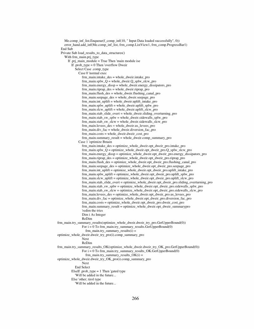
266
Me.comp_inf_list.Enqueue(f_comp_inf(10, " Input Data loaded successfully", 0)) error_hand.add_inf(Me.comp_inf_list, frm_comp.ListView1, frm_comp.ProgressBar1) End Sub Private Sub load_results_to_data_structures() With frm_main.prj_type If .prj_main_module = True Then 'main module ise If .prob_type = 0 Then 'overflow Dweir Select Case .comp_type Case 0 'normal exec frm_main.intake_des = whole_dweir.intake_pro frm_main.splw_Q = whole_dweir.Q_splw_slcw_pro frm_main.energy_dissp = whole_dweir.energy_dissipators_pro frm_main.riprap_des = whole_dweir.riprap_pro frm_main.flush_des = whole_dweir.flushing_canal_pro frm_main.seepage_des = whole_dweir.seepage_pro frm_main.int_uplift = whole_dweir.uplift_intake_pro frm_main.splw_uplift = whole_dweir.uplift_splw_pro frm_main.slcw_uplift = whole_dweir.uplift_slcw_pro frm_main.stab_slide_overt = whole_dweir.sliding_overturning_pro frm_main.stab_sw_splw = whole_dweir.sidewalls_splw_pro frm_main.stab_sw_slcw = whole_dweir.sidewalls_slcw_pro frm_main.levees_des = whole_dweir.us_levees_pro frm_main.div_fac = whole_dweir.diversion_fac_pro frm_main.costs = whole_dweir.dweir_cost_pro frm_main.summary_result = whole_dweir.comp_summary_pro Case 1 'optimize Bmain frm_main.intake_des = optimize_whole_dweir.opt_dweir_pro.intake_pro frm_main.splw_Q = optimize_whole_dweir.opt_dweir_pro.Q_splw_slcw_pro frm_main.energy_dissp = optimize_whole_dweir.opt_dweir_pro.energy_dissipators_pro frm_main.riprap_des = optimize_whole_dweir.opt_dweir_pro.riprap_pro frm_main.flush_des = optimize_whole_dweir.opt_dweir_pro.flushing_canal_pro frm_main.seepage_des = optimize_whole_dweir.opt_dweir_pro.seepage_pro frm_main.int_uplift = optimize_whole_dweir.opt_dweir_pro.uplift_intake_pro frm_main.splw_uplift = optimize_whole_dweir.opt_dweir_pro.uplift_splw_pro frm_main.slcw_uplift = optimize_whole_dweir.opt_dweir_pro.uplift_slcw_pro frm_main.stab_slide_overt = optimize_whole_dweir.opt_dweir_pro.sliding_overturning_pro frm_main.stab_sw_splw = optimize_whole_dweir.opt_dweir_pro.sidewalls_splw_pro frm_main.stab_sw_slcw = optimize_whole_dweir.opt_dweir_pro.sidewalls_slcw_pro frm_main.levees_des = optimize_whole_dweir.opt_dweir_pro.us_levees_pro frm_main.div_fac = optimize_whole_dweir.opt_dweir_pro.diversion_fac_pro frm_main.costs = optimize_whole_dweir.opt_dweir_pro.dweir_cost_pro frm_main.summary_result = optimize_whole_dweir.opt_dweir_summarypro 'redim the tries Dim i As Integer ReDim frm_main.try_summary_results(optimize_whole_dweir.dweir_try_pro.GetUpperBound(0)) For i = 0 To frm_main.try_summary_results.GetUpperBound(0) frm_main.try_summary_results(i) = optimize_whole_dweir.dweir_try_pro(i).comp_summary_pro Next ReDim frm_main.try_summary_results_OK(optimize_whole_dweir.dweir_try_OK_pro.GetUpperBound(0)) For i = 0 To frm_main.try_summary_results_OK.GetUpperBound(0) frm_main.try_summary_results_OK(i) = optimize_whole_dweir.dweir_try_OK_pro(i).comp_summary_pro Next End Select ElseIf .prob_type = 1 Then 'gated type 'Will be added in the future... Else 'other; tirol type 'Will be added in the future...

267
End If Else 'secondary module 'Will be added in the future... End If End With load_obj_states() Me.comp_inf_list.Enqueue(f_comp_inf(100, " COMPUTATION ENDS", 0)) error_hand.add_inf(Me.comp_inf_list, frm_comp.ListView1, frm_comp.ProgressBar1) End Sub Public Shared Sub load_obj_states() 'load the objects states With frm_main.obj_state .st_div_fac = Not IsNothing(frm_main.div_fac) .st_energy_dissp = Not IsNothing(frm_main.energy_dissp) .st_flush_des = Not IsNothing(frm_main.flush_des) .st_int_uplift = Not IsNothing(frm_main.int_uplift) .st_intake_des = Not IsNothing(frm_main.intake_des) .st_levees_des = Not IsNothing(frm_main.levees_des) .st_costs = Not IsNothing(frm_main.costs) .st_riprap_des = Not IsNothing(frm_main.riprap_des) .st_seepage_des = Not IsNothing(frm_main.seepage_des) .st_slcw_uplift = Not IsNothing(frm_main.slcw_uplift) .st_splw_Q = Not IsNothing(frm_main.splw_Q) .st_splw_uplift = Not IsNothing(frm_main.splw_uplift) .st_stab_slide_overt = Not IsNothing(frm_main.stab_slide_overt) .st_stab_sw_splw = Not IsNothing(frm_main.stab_sw_splw) .st_stab_sw_slcw = Not IsNothing(frm_main.stab_sw_slcw) .st_summary_result = Not IsNothing(frm_main.summary_result) .st_try_summary_results = Not IsNothing(frm_main.try_summary_results) .st_try_summary_results_OK = Not IsNothing(frm_main.try_summary_results_OK) End With End Sub Private Sub compute() 'call the compute process form Me.comp_inf_list.Enqueue(f_comp_inf(5, " COMPUTATION STARTS", 0)) error_hand.add_inf(Me.comp_inf_list, frm_comp.ListView1, frm_comp.ProgressBar1) Dim i As Integer = 0 With frm_main.prj_type If .prj_main_module = True Then 'main module ise If .prob_type = 0 Then 'overflow Dweir Me.load_final_input_data_struct_for_comp() Select Case .comp_type Case 0 'normal exec whole_dweir = New whole_dweir(inp_whole_dweir, Me.comp_inf_list, frm_comp.ListView1, frm_comp.ProgressBar1) whole_dweir.compute() load_results_to_data_structures() Case 1 'optimize Bmain optimize_whole_dweir = New optimize_Bmain(inp_whole_dweir, Me.comp_inf_list, frm_comp.ListView1, frm_comp.ProgressBar1) optimize_whole_dweir.compute() load_results_to_data_structures() End Select ElseIf .prob_type = 1 Then 'gated type 'Will be added in the future... Else 'other; tirol type 'Will be added in the future... End If Else 'secondary module 'Will be added in the future... End If

268
End With frm_comp.Button1.Text = "CLOSE" End Sub #End Region 'only one radio button is necessary, one click , others unclicked Private Sub RadioButton1_CheckedChanged(ByVal sender As System.Object, ByVal e As System.EventArgs) Handles RadioButton1.CheckedChanged If Me.RadioButton1.Checked = True Then frm_main.prj_type.comp_type = 0 'normal exec ElseIf Me.RadioButton2.Checked = True Then frm_main.prj_type.comp_type = 1 'optimize Bmain End If Me.load_prj_inf() End Sub Private Sub RadioButton2_CheckedChanged(ByVal sender As System.Object, ByVal e As System.EventArgs) Handles RadioButton2.CheckedChanged Me.load_prj_inf() End Sub Private Sub Button1_Click(ByVal sender As System.Object, ByVal e As System.EventArgs) Handles Button1.Click 'always start from 0 (zero) in all our logic If Me.RadioButton1.Checked = True Then frm_main.prj_type.comp_type = 0 'normal exec ElseIf Me.RadioButton2.Checked = True Then frm_main.prj_type.comp_type = 1 'optimize Bmain End If thr = New Threading.Thread(AddressOf compute) Me.Hide() frm_comp = New frm_comp_process() thr.Start() frm_comp.ShowDialog() 'thr.IsBackground = True ' End Sub End Class '*---------------------------------------------------------------------------------------------------------------------------------* '| END OF FORM-3 | '*---------------------------------------------------------------------------------------------------------------------------------* '*---------------------------------------------------------------------------------------------------------------------------------* '| FORM-8 : Form8.vb | '*---------------------------------------------------------------------------------------------------------------------------------* Public Class frm_comp_process Inherits System.Windows.Forms.Form #Region " Windows Form Designer generated code " Public Sub New() MyBase.New() 'This call is required by the Windows Form Designer. InitializeComponent() 'Add any initialization after the InitializeComponent() call End Sub 'Form overrides dispose to clean up the component list. Protected Overloads Overrides Sub Dispose(ByVal disposing As Boolean) If disposing Then If Not (components Is Nothing) Then components.Dispose() End If End If MyBase.Dispose(disposing) End Sub

269
'Required by the Windows Form Designer Private components As System.ComponentModel.IContainer 'NOTE: The following procedure is required by the Windows Form Designer 'It can be modified using the Windows Form Designer. 'Do not modify it using the code editor. ‘This part of code is generated automatically. Details are hidden. #End Region Private Sub frm_comp_process_Load(ByVal sender As System.Object, ByVal e As System.EventArgs) Handles MyBase.Load End Sub Private Sub Button1_Click(ByVal sender As System.Object, ByVal e As System.EventArgs) Handles Button1.Click If Me.Button1.Text = "STOP COMPUTATION" Then frm_main.frm_computec.thr.Suspend() Me.Button1.Text = "RESUME COMPUTATION" ElseIf Me.Button1.Text = "RESUME COMPUTATION" Then Me.Button1.Text = "STOP COMPUTATION" frm_main.frm_computec.thr.Resume() ElseIf Me.Button1.Text = "CLOSE" Then Me.Dispose() End If End Sub Private Sub frm_comp_process_Closed(ByVal sender As Object, ByVal e As System.EventArgs) Handles MyBase.Closed frm_main.frm_computec.Dispose() End Sub End Class '*---------------------------------------------------------------------------------------------------------------------------------* '| END OF FORM-8 | '*---------------------------------------------------------------------------------------------------------------------------------* '*---------------------------------------------------------------------------------------------------------------------------------* '| FORM-9 : Form9.vb | '*---------------------------------------------------------------------------------------------------------------------------------* Public Class frm_prj_type Inherits System.Windows.Forms.Form #Region " Windows Form Designer generated code " Public Sub New() MyBase.New() 'This call is required by the Windows Form Designer. InitializeComponent() 'Add any initialization after the InitializeComponent() call End Sub 'Form overrides dispose to clean up the component list. Protected Overloads Overrides Sub Dispose(ByVal disposing As Boolean) If disposing Then If Not (components Is Nothing) Then components.Dispose() End If End If MyBase.Dispose(disposing) End Sub 'Required by the Windows Form Designer Private components As System.ComponentModel.IContainer 'NOTE: The following procedure is required by the Windows Form Designer 'It can be modified using the Windows Form Designer. 'Do not modify it using the code editor. ‘This part of code is generated automatically. Details are hidden.

270
#End Region Private Sub ToolBar1_ButtonClick(ByVal sender As System.Object, ByVal e As System.Windows.Forms.ToolBarButtonClickEventArgs) Handles ToolBar1.ButtonClick Me.Button1.Enabled = False 'in order to force the user to select a prj type With Me.ListView1 Select Case Me.ToolBar1.Buttons.IndexOf(e.Button) Case 0 'main modules Me.ToolBarButton1.Pushed = True Me.ToolBarButton2.Pushed = False load_list_view(True) frm_main.prj_type.prj_main_module = True Case 1 'secondary modules Me.ToolBarButton1.Pushed = False Me.ToolBarButton2.Pushed = True load_list_view(False) frm_main.prj_type.prj_main_module = False End Select End With End Sub Private Sub load_list_view(ByVal main_module As Boolean) With Me.ListView1 .Clear() If main_module = True Then .Items.Add("Diversion Weir with Overflow Spillway", 0) ' .Items.Add("Gated Diversion Weir", 1) to be added in the future Else .Items.Add("Intake Hydraulics", 2) .Items.Add("Discharges and Energy Dissipators", 3) .Items.Add("Seepage Analysis", 4) .Items.Add("Intake Stability Analysis against Uplift", 5) .Items.Add("Spillway Body+Apron Stability Analysis", 6) .Items.Add("Sidewalls", 7) .Items.Add("Upstream Levees", 8 .Items.Add("Riprap Design", 9) .Items.Add("Flushing Canal", 10) .Items.Add("Diversion Facility", 11) End If End With End Sub Private Sub frm_prj_type_Load(ByVal sender As System.Object, ByVal e As System.EventArgs) Handles MyBase.Load 'default is the main_module load_list_view(True) frm_main.prj_type.prj_main_module = True End Sub Private Sub Button1_Click(ByVal sender As System.Object, ByVal e As System.EventArgs) Handles Button1.Click frm_main.prj_type.prob_type = Me.ListView1.FocusedItem.Index Me.Dispose() End Sub Private Sub ListView1_DoubleClick(ByVal sender As Object, ByVal e As System.EventArgs) Handles ListView1.DoubleClick frm_main.prj_type.prob_type = Me.ListView1.FocusedItem.Index Me.Dispose() End Sub Private Sub ListView1_SelectedIndexChanged(ByVal sender As System.Object, ByVal e As System.EventArgs) Handles ListView1.SelectedIndexChanged Me.Button1.Enabled = True End Sub Private Sub Button2_Click(ByVal sender As System.Object, ByVal e As System.EventArgs) Handles Button2.Click
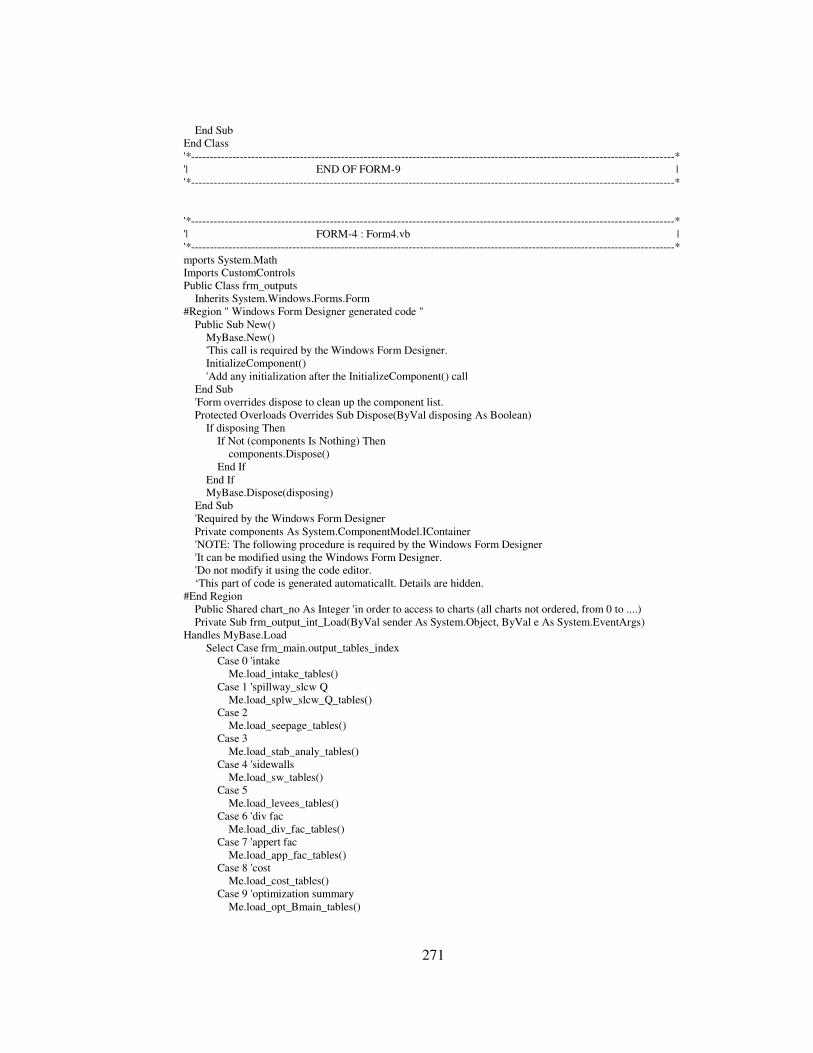
271
End Sub End Class '*---------------------------------------------------------------------------------------------------------------------------------* '| END OF FORM-9 | '*---------------------------------------------------------------------------------------------------------------------------------* '*---------------------------------------------------------------------------------------------------------------------------------* '| FORM-4 : Form4.vb | '*---------------------------------------------------------------------------------------------------------------------------------* mports System.Math Imports CustomControls Public Class frm_outputs Inherits System.Windows.Forms.Form #Region " Windows Form Designer generated code " Public Sub New() MyBase.New() 'This call is required by the Windows Form Designer. InitializeComponent() 'Add any initialization after the InitializeComponent() call End Sub 'Form overrides dispose to clean up the component list. Protected Overloads Overrides Sub Dispose(ByVal disposing As Boolean) If disposing Then If Not (components Is Nothing) Then components.Dispose() End If End If MyBase.Dispose(disposing) End Sub 'Required by the Windows Form Designer Private components As System.ComponentModel.IContainer 'NOTE: The following procedure is required by the Windows Form Designer 'It can be modified using the Windows Form Designer. 'Do not modify it using the code editor. ‘This part of code is generated automaticallt. Details are hidden. #End Region Public Shared chart_no As Integer 'in order to access to charts (all charts not ordered, from 0 to ....) Private Sub frm_output_int_Load(ByVal sender As System.Object, ByVal e As System.EventArgs) Handles MyBase.Load Select Case frm_main.output_tables_index Case 0 'intake Me.load_intake_tables() Case 1 'spillway_slcw Q Me.load_splw_slcw_Q_tables() Case 2 Me.load_seepage_tables() Case 3 Me.load_stab_analy_tables() Case 4 'sidewalls Me.load_sw_tables() Case 5 Me.load_levees_tables() Case 6 'div fac Me.load_div_fac_tables() Case 7 'appert fac Me.load_app_fac_tables() Case 8 'cost Me.load_cost_tables() Case 9 'optimization summary Me.load_opt_Bmain_tables()

272
End Select End Sub #Region "my procedures" #Region "intake tables" Private Sub load_intake_tables() Me.ToolBarButton2.DropDownMenu = Me.mnu_int_tables Me.ToolBarButton3.DropDownMenu = Me.mnu_int_graphs 'check if object is loaded (referenced) If IsNothing(frm_main.intake_des) = False Then Me.load_int_out() Me.load_int_out2() End If Me.GroupBox1.Text = "Outputs of the Intake computations" 'show the default table Me.DataGridEx2.CaptionText = "Intake Water Surface Profile Table:" Me.DataGridEx2.AdjustColumnWidths(Me.dtbln_out_int) Me.DataGridEx2.DataSource = Me.dtbln_out_int End Sub Private Sub load_int_out() End Sub #End Region #Region "spillway and sluiceway discharge and energy dissipators table" Private Sub load_splw_slcw_Q_tables() Me.ToolBarButton2.DropDownMenu = Me.mnu_splw_slcw_Q_tables Me.ToolBarButton3.DropDownMenu = Me.mnu_splw_slcw_Q_graphs 'check if object is loaded (referenced) If IsNothing(frm_main.splw_Q) = False Then Me.load_splw_slcw_Q_out() End If If IsNothing(frm_main.energy_dissp) = False Then Me.load_energy_dissp_out() End If Me.GroupBox1.Text = "Outputs of the Spillway-Sluiceway discharge computations and corresponding energy dissipators" 'show the default table Me.DataGridEx2.CaptionText = "Spillway - Sluiceway Discharge Table:" Me.DataGridEx2.AdjustColumnWidths(Me.dtbln_out_splw_slcw) Me.DataGridEx2.DataSource = Me.dtbln_out_splw_slcw End Sub Private Sub load_splw_slcw_Q_out() End Sub Private Sub load_energy_dissp_out() End Sub #End Region #Region "Seepage analysis tables" Private Sub load_seepage_tables() Me.ToolBarButton2.DropDownMenu = Me.mnu_seepage Me.ToolBarButton3.DropDownMenu = Me.mnu_seepage_graphs 'check if object is loaded (referenced) If IsNothing(frm_main.seepage_des) = False Then Me.load_seepage_out() End If Me.GroupBox1.Text = "Outputs of the Seepage computations" 'show the default table Me.DataGridEx2.CaptionText = "Seepage Computations Results Table:" Me.DataGridEx2.AdjustColumnWidths(Me.dtbln_out_seepage) Me.DataGridEx2.DataSource = Me.dtbln_out_seepage End Sub Private Sub load_seepage_out() Dim i As Integer Dim x As DataRow

273
With frm_main.seepage_des 'values For i = 0 To .inp_K_pro.GetUpperBound(0) + 4 '+3 for columns; description, symbols and units, full u/s no tailwater case Me.dtbln_out_seepage.Columns.Add(i + 1, Type.GetType("System.String")) Next For i = 0 To Me.dtbln_out_seepage.Columns.Count - 1 Me.dtbln_out_seepage.Columns(i).DefaultValue = "" Next 'insert output data x = Me.dtbln_out_seepage.NewRow x(0) = "MAX NET HEAD TABLE" Me.dtbln_out_seepage.Rows.Add(x) x = Me.dtbln_out_seepage.NewRow x(0) = "Description" x(1) = "Symbols" x(2) = "Units" Me.dtbln_out_seepage.Rows.Add(x) 'cases x = Me.dtbln_out_seepage.NewRow x(0) = "Flow case" x(1) = "" x(2) = "" For i = 0 To .inp_K_pro.GetUpperBound(0) x(i + 3) = "Overflowing" Next x(i + 3) = "Full u/s no tailwater" Me.dtbln_out_seepage.Rows.Add(x) 'flow profile x = Me.dtbln_out_seepage.NewRow x(0) = "Flow Profile" x(1) = "" x(2) = "" For i = 0 To .inp_K_pro.GetUpperBound(0) x(i + 3) = .profile_pro(i) Next Me.dtbln_out_seepage.Rows.Add(x) 'Ku x = Me.dtbln_out_seepage.NewRow x(0) = "upstream water surface elevation" x(1) = "Ku" x(2) = "(m.)" For i = 0 To .inp_K_pro.GetUpperBound(0) x(i + 3) = .inp_K_pro(i) Next Me.dtbln_out_seepage.Rows.Add(x) 'Kd x = Me.dtbln_out_seepage.NewRow x(0) = "tailwater water surface elevation" x(1) = "Kd" x(2) = "(m.)" For i = 0 To .inp_K_pro.GetUpperBound(0) x(i + 3) = .inp_Kd_pro(i) Next Me.dtbln_out_seepage.Rows.Add(x) 'Ks x = Me.dtbln_out_seepage.NewRow x(0) = "crest elev. of spillway" x(1) = "Ks" x(2) = "(m.)" x(Me.dtbln_out_seepage.Columns.Count - 1) = .inp_Ks_pro

274
Me.dtbln_out_seepage.Rows.Add(x) 'Kr x = Me.dtbln_out_seepage.NewRow x(0) = "tailwater bottom elevation" x(1) = "Kr" x(2) = "(m.)" x(Me.dtbln_out_seepage.Columns.Count - 1) = .inp_Kr_pro Me.dtbln_out_seepage.Rows.Add(x) 'H x = Me.dtbln_out_seepage.NewRow x(0) = "net head" x(1) = "H" x(2) = "(m.)" For i = 0 To .inp_K_pro.GetUpperBound(0) x(i + 3) = .H_overf_pro(i) Next x(Me.dtbln_out_seepage.Columns.Count - 1) = .H_funtw_pro Me.dtbln_out_seepage.Rows.Add(x) x = Me.dtbln_out_seepage.NewRow Me.dtbln_out_seepage.Rows.Add(x) x = Me.dtbln_out_seepage.NewRow Me.dtbln_out_seepage.Rows.Add(x) 'seepage path table x = Me.dtbln_out_seepage.NewRow x(0) = "SEEPAGE PATH TABLE" Me.dtbln_out_seepage.Rows.Add(x) x = Me.dtbln_out_seepage.NewRow x(0) = "Description" x(1) = "X-coordinate" x(2) = "Y-coordinate" x(3) = "creep length" Me.dtbln_out_seepage.Rows.Add(x) x = Me.dtbln_out_seepage.NewRow x(0) = "Symbols" x(1) = "x" x(2) = "y" x(3) = "ELx" Me.dtbln_out_seepage.Rows.Add(x) x = Me.dtbln_out_seepage.NewRow x(0) = "Units" x(1) = "(m.)" x(2) = "(m.)" x(3) = "(m.)" Me.dtbln_out_seepage.Rows.Add(x) For i = 0 To .inp_creep_path_pro.GetUpperBound(0) x = Me.dtbln_out_seepage.NewRow x(0) = "Point-" & i + 1 x(1) = .inp_creep_path_pro(i).x x(2) = .inp_creep_path_pro(i).y x(3) = .ELx_pro(i) Me.dtbln_out_seepage.Rows.Add(x) Next x = Me.dtbln_out_seepage.NewRow Me.dtbln_out_seepage.Rows.Add(x) x = Me.dtbln_out_seepage.NewRow Me.dtbln_out_seepage.Rows.Add(x) 'summary x = Me.dtbln_out_seepage.NewRow x(0) = "SUMMARY OF THE RESULTS" Me.dtbln_out_seepage.Rows.Add(x) x = Me.dtbln_out_seepage.NewRow

275
x(0) = "Description" x(1) = "Symbols" x(2) = "Units" Me.dtbln_out_seepage.Rows.Add(x) 'max Hnet x = Me.dtbln_out_seepage.NewRow x(0) = "max net head" x(1) = "Hnet_max" x(2) = "(m.)" x(3) = .Hnet_pro Me.dtbln_out_seepage.Rows.Add(x) 'C x = Me.dtbln_out_seepage.NewRow x(0) = "relative permeability" x(1) = "C" x(2) = "" x(3) = .inp_C_pro Me.dtbln_out_seepage.Rows.Add(x) 'CH x = Me.dtbln_out_seepage.NewRow x(0) = "min. required creep length for no piping" x(1) = "C*H" x(2) = "(m.)" x(3) = .CH_pro Me.dtbln_out_seepage.Rows.Add(x) 'Lcr x = Me.dtbln_out_seepage.NewRow x(0) = "calculated creep length" x(1) = "Lcr" x(2) = "(m.)" x(3) = .Lcr_pro Me.dtbln_out_seepage.Rows.Add(x) 'satisfactory x = Me.dtbln_out_seepage.NewRow x(0) = "Satisfactory" x(1) = "Lcr > C*H" x(2) = "" x(3) = IIf(.satisfactory_pro, "OK", "not OK") Me.dtbln_out_seepage.Rows.Add(x) End With End Sub #End Region #Region "Stability Analysis tables" Private Sub load_stab_analy_tables() Me.ToolBarButton2.DropDownMenu = Me.mnu_stab Me.ToolBarButton3.DropDownMenu = Nothing 'no graph 'check if object is loaded (referenced) If Not IsNothing(frm_main.int_uplift) Then Me.load_stab_uplift_int_out() End If If Not IsNothing(frm_main.splw_uplift) Then Me.load_stab_uplift_splw_out() End If If Not IsNothing(frm_main.slcw_uplift) Then Me.load_stab_uplift_slcw_out() End If If Not IsNothing(frm_main.stab_slide_overt) Then Me.load_stab_sliding_out() Me.load_stab_overt_out_funt() Me.load_stab_overt_out_er_wrt_toe() Me.load_stab_overt_out_er_wrt_heel()

276
End If Me.GroupBox1.Text = "Outputs of the Stability Analysis" 'show the default table Me.DataGridEx2.CaptionText = "Intake Stability against Uplift Results Table:" Me.DataGridEx2.AdjustColumnWidths(Me.dtbln_out_stab_upl_int) Me.DataGridEx2.DataSource = Me.dtbln_out_stab_upl_int End Sub Private Sub load_stab_uplift_int_out() Dim i As Integer Dim x As DataRow With frm_main.int_uplift 'create columns For i = 0 To 6 Me.dtbln_out_stab_upl_int.Columns.Add(i + 1, Type.GetType("System.String")) Next For i = 0 To Me.dtbln_out_stab_upl_int.Columns.Count - 1 Me.dtbln_out_stab_upl_int.Columns(i).DefaultValue = "" Next 'insert output data 'seepage table x = Me.dtbln_out_stab_upl_int.NewRow x(0) = "SEEPAGE TABLE" Me.dtbln_out_stab_upl_int.Rows.Add(x) 'headers x = Me.dtbln_out_stab_upl_int.NewRow x(0) = "Description" x(1) = "X-coordinate" x(2) = "Y-coordinate" x(3) = "Creep length" x(4) = "head loss" x(5) = "Static head" x(6) = "uplift pressure" Me.dtbln_out_stab_upl_int.Rows.Add(x) 'symbols x = Me.dtbln_out_stab_upl_int.NewRow x(0) = "Symbols" x(1) = "X" x(2) = "Y" x(3) = "ELx" x(4) = "hx" x(5) = "H" x(6) = "ux" Me.dtbln_out_stab_upl_int.Rows.Add(x) 'units x = Me.dtbln_out_stab_upl_int.NewRow x(0) = "Units" x(1) = "(m.)" x(2) = "(m.)" x(3) = "(m.)" x(4) = "(m.)" x(5) = "(m.)" x(6) = "(m.)" Me.dtbln_out_stab_upl_int.Rows.Add(x) 'values For i = 0 To .input_geom_pro.creep_path.GetUpperBound(0) x = Me.dtbln_out_stab_upl_int.NewRow x(0) = "Point-" & i + 1 x(1) = .input_geom_pro.creep_path(i).x x(2) = .input_geom_pro.creep_path(i).y x(3) = .ELx_pro(i) x(4) = .hx_pro(i)

277
x(5) = .shead_pro(i) x(6) = .ux_pro(i) Me.dtbln_out_stab_upl_int.Rows.Add(x) Next x = Me.dtbln_out_stab_upl_int.NewRow Me.dtbln_out_stab_upl_int.Rows.Add(x) 'summary of the results x = Me.dtbln_out_stab_upl_int.NewRow x(0) = "RESULTS OF SEEPAGE CALCULATION" Me.dtbln_out_stab_upl_int.Rows.Add(x) x = Me.dtbln_out_stab_upl_int.NewRow x(0) = "Description" x(1) = "Symbols" x(2) = "Units" Me.dtbln_out_stab_upl_int.Rows.Add(x) 'ELx x = Me.dtbln_out_stab_upl_int.NewRow x(0) = "Total creep length" x(1) = "ELx" x(2) = "(m.)" x(3) = .Lcr_pro Me.dtbln_out_stab_upl_int.Rows.Add(x) 'Hnet x = Me.dtbln_out_stab_upl_int.NewRow x(0) = "Net head" x(1) = "H" x(2) = "(m.)" x(3) = .Hnet_pro Me.dtbln_out_stab_upl_int.Rows.Add(x) 'head loss per unit length x = Me.dtbln_out_stab_upl_int.NewRow x(0) = "head loss per unit length" x(1) = "H / ELx" x(2) = "" x(3) = .hl_per_Lx_pro Me.dtbln_out_stab_upl_int.Rows.Add(x) x = Me.dtbln_out_stab_upl_int.NewRow Me.dtbln_out_stab_upl_int.Rows.Add(x) x = Me.dtbln_out_stab_upl_int.NewRow Me.dtbln_out_stab_upl_int.Rows.Add(x) 'Stability table x = Me.dtbln_out_stab_upl_int.NewRow x(0) = "UPLIFT STABILITY TABLE" Me.dtbln_out_stab_upl_int.Rows.Add(x) 'headers x = Me.dtbln_out_stab_upl_int.NewRow x(0) = "Description" x(1) = "Symbols" x(2) = "Units" Me.dtbln_out_stab_upl_int.Rows.Add(x) 'Wa x = Me.dtbln_out_stab_upl_int.NewRow x(0) = "weight of basin" x(1) = "Wa" x(2) = "(kN/m)" x(3) = .Wa_pro Me.dtbln_out_stab_upl_int.Rows.Add(x) 'Fu x = Me.dtbln_out_stab_upl_int.NewRow x(0) = "Uplift force" x(1) = "Fu"

278
x(2) = "(kN/m)" x(3) = .Fu_pro Me.dtbln_out_stab_upl_int.Rows.Add(x) 'drains add x = Me.dtbln_out_stab_upl_int.NewRow x(0) = "drains added" x(1) = "" x(2) = "" x(3) = IIf(.drains_add_pro, "YES", "NO") Me.dtbln_out_stab_upl_int.Rows.Add(x) If .drains_add_pro Then 'drains add x = Me.dtbln_out_stab_upl_int.NewRow x(0) = "uplift reduction coeff" x(1) = "Fi" x(2) = "" x(3) = 1 - .inp_ured_perc_pro Me.dtbln_out_stab_upl_int.Rows.Add(x) 'Fu_final x = Me.dtbln_out_stab_upl_int.NewRow x(0) = "reduced uplift force" x(1) = "Fu_red" x(2) = "(kN/m)" x(3) = .Fu_final_pro Me.dtbln_out_stab_upl_int.Rows.Add(x) End If 'Factor of safety x = Me.dtbln_out_stab_upl_int.NewRow x(0) = "Factor of safety" x(1) = "FSu" x(2) = "" x(3) = .Fsu_final_pro Me.dtbln_out_stab_upl_int.Rows.Add(x) 'Satisfactory x = Me.dtbln_out_stab_upl_int.NewRow x(0) = "Satisfactory" x(1) = IIf(.satisfactory_pro, "FSu >= " & .Fsu_pro, "FSu < " & .Fsu_pro) x(2) = "" x(3) = IIf(.satisfactory_pro, "OK", "not OK") Me.dtbln_out_stab_upl_int.Rows.Add(x) End With End Sub Private Sub load_stab_uplift_splw_out() Dim i As Integer Dim x As DataRow With frm_main.splw_uplift 'create columns For i = 0 To 6 Me.dtbln_out_stab_upl_splw.Columns.Add(i + 1, Type.GetType("System.String")) Next For i = 0 To Me.dtbln_out_stab_upl_splw.Columns.Count - 1 Me.dtbln_out_stab_upl_splw.Columns(i).DefaultValue = "" Next 'insert output data 'seepage table x = Me.dtbln_out_stab_upl_splw.NewRow x(0) = "SEEPAGE TABLE" Me.dtbln_out_stab_upl_splw.Rows.Add(x) 'headers x = Me.dtbln_out_stab_upl_splw.NewRow x(0) = "Description"

279
x(1) = "X-coordinate" x(2) = "Y-coordinate" x(3) = "Creep length" x(4) = "head loss" x(5) = "Static head" x(6) = "uplift pressure" Me.dtbln_out_stab_upl_splw.Rows.Add(x) 'symbols x = Me.dtbln_out_stab_upl_splw.NewRow x(0) = "Symbols" x(1) = "X" x(2) = "Y" x(3) = "ELx" x(4) = "hx" x(5) = "H" x(6) = "ux" Me.dtbln_out_stab_upl_splw.Rows.Add(x) 'units x = Me.dtbln_out_stab_upl_splw.NewRow x(0) = "Units" x(1) = "(m.)" x(2) = "(m.)" x(3) = "(m.)" x(4) = "(m.)" x(5) = "(m.)" x(6) = "(m.)" Me.dtbln_out_stab_upl_splw.Rows.Add(x) 'values For i = 0 To .input_geom_pro.creep_path.GetUpperBound(0) x = Me.dtbln_out_stab_upl_splw.NewRow x(0) = "Point-" & i + 1 x(1) = .input_geom_pro.creep_path(i).x x(2) = .input_geom_pro.creep_path(i).y x(3) = .ELx_pro(i) x(4) = .hx_pro(i) x(5) = .shead_pro(i) x(6) = .ux_pro(i) Me.dtbln_out_stab_upl_splw.Rows.Add(x) Next x = Me.dtbln_out_stab_upl_splw.NewRow Me.dtbln_out_stab_upl_splw.Rows.Add(x) 'summary of the results 'summary of the results x = Me.dtbln_out_stab_upl_splw.NewRow x(0) = "RESULTS OF SEEPAGE CALCULATION" Me.dtbln_out_stab_upl_splw.Rows.Add(x) x = Me.dtbln_out_stab_upl_splw.NewRow x(0) = "Description" x(1) = "Symbols" x(2) = "Units" Me.dtbln_out_stab_upl_splw.Rows.Add(x) 'ELx x = Me.dtbln_out_stab_upl_splw.NewRow x(0) = "Total creep length" x(1) = "ELx" x(2) = "(m.)" x(3) = .Lcr_pro Me.dtbln_out_stab_upl_splw.Rows.Add(x) 'Hnet x = Me.dtbln_out_stab_upl_splw.NewRow x(0) = "Net head"

280
x(1) = "H" x(2) = "(m.)" x(3) = .Hnet_pro Me.dtbln_out_stab_upl_splw.Rows.Add(x) 'head loss per unit length x = Me.dtbln_out_stab_upl_splw.NewRow x(0) = "head loss per unit length" x(1) = "H / ELx" x(2) = "" x(3) = .hl_per_Lx_pro Me.dtbln_out_stab_upl_splw.Rows.Add(x) x = Me.dtbln_out_stab_upl_splw.NewRow Me.dtbln_out_stab_upl_splw.Rows.Add(x) x = Me.dtbln_out_stab_upl_splw.NewRow Me.dtbln_out_stab_upl_splw.Rows.Add(x) 'Stability table x = Me.dtbln_out_stab_upl_splw.NewRow x(0) = "UPLIFT STABILITY TABLE" Me.dtbln_out_stab_upl_splw.Rows.Add(x) 'headers x = Me.dtbln_out_stab_upl_splw.NewRow x(0) = "Description" x(1) = "Symbols" x(2) = "Units" Me.dtbln_out_stab_upl_splw.Rows.Add(x) 'Wa x = Me.dtbln_out_stab_upl_splw.NewRow x(0) = "weight of basin" x(1) = "Wa" x(2) = "(kN/m)" x(3) = .Wa_pro Me.dtbln_out_stab_upl_splw.Rows.Add(x) 'Fu x = Me.dtbln_out_stab_upl_splw.NewRow x(0) = "Uplift force" x(1) = "Fu" x(2) = "(kN/m)" x(3) = .Fu_pro Me.dtbln_out_stab_upl_splw.Rows.Add(x) 'drains add x = Me.dtbln_out_stab_upl_splw.NewRow x(0) = "drains added" x(1) = "" x(2) = "" x(3) = IIf(.drains_add_pro, "YES", "NO") Me.dtbln_out_stab_upl_splw.Rows.Add(x) If .drains_add_pro Then 'drains add x = Me.dtbln_out_stab_upl_splw.NewRow x(0) = "uplift reduction coeff" x(1) = "Fi" x(2) = "" x(3) = 1 - .inp_ured_perc_pro Me.dtbln_out_stab_upl_splw.Rows.Add(x) 'Fu_final x = Me.dtbln_out_stab_upl_splw.NewRow x(0) = "reduced uplift force" x(1) = "Fu_red" x(2) = "(kN/m)" x(3) = .Fu_final_pro Me.dtbln_out_stab_upl_splw.Rows.Add(x)

281
End If 'Factor of safety x = Me.dtbln_out_stab_upl_splw.NewRow x(0) = "Factor of safety" x(1) = "FSu" x(2) = "" x(3) = .Fsu_final_pro Me.dtbln_out_stab_upl_splw.Rows.Add(x) 'Satisfactory x = Me.dtbln_out_stab_upl_splw.NewRow x(0) = "Satisfactory" x(1) = IIf(.satisfactory_pro, "FSu >= " & .Fsu_pro, "FSu < " & .Fsu_pro) x(2) = "" x(3) = IIf(.satisfactory_pro, "OK", "not OK") Me.dtbln_out_stab_upl_splw.Rows.Add(x) End With End Sub Private Sub load_stab_uplift_slcw_out() Dim i As Integer Dim x As DataRow With frm_main.slcw_uplift 'create columns For i = 0 To 6 Me.dtbln_out_stab_upl_slcw.Columns.Add(i + 1, Type.GetType("System.String")) Next For i = 0 To Me.dtbln_out_stab_upl_slcw.Columns.Count - 1 Me.dtbln_out_stab_upl_slcw.Columns(i).DefaultValue = "" Next 'insert output data 'seepage table x = Me.dtbln_out_stab_upl_slcw.NewRow x(0) = "SEEPAGE TABLE" Me.dtbln_out_stab_upl_slcw.Rows.Add(x) 'headers x = Me.dtbln_out_stab_upl_slcw.NewRow x(0) = "Description" x(1) = "X-coordinate" x(2) = "Y-coordinate" x(3) = "Creep length" x(4) = "head loss" x(5) = "Static head" x(6) = "uplift pressure" Me.dtbln_out_stab_upl_slcw.Rows.Add(x) 'symbols x = Me.dtbln_out_stab_upl_slcw.NewRow x(0) = "Symbols" x(1) = "X" x(2) = "Y" x(3) = "ELx" x(4) = "hx" x(5) = "H" x(6) = "ux" Me.dtbln_out_stab_upl_slcw.Rows.Add(x) 'units x = Me.dtbln_out_stab_upl_slcw.NewRow x(0) = "Units" x(1) = "(m.)" x(2) = "(m.)" x(3) = "(m.)" x(4) = "(m.)" x(5) = "(m.)"

282
x(6) = "(m.)" Me.dtbln_out_stab_upl_slcw.Rows.Add(x) 'values For i = 0 To .input_geom_pro.creep_path.GetUpperBound(0) x = Me.dtbln_out_stab_upl_slcw.NewRow x(0) = "Point-" & i + 1 x(1) = .input_geom_pro.creep_path(i).x x(2) = .input_geom_pro.creep_path(i).y x(3) = .ELx_pro(i) x(4) = .hx_pro(i) x(5) = .shead_pro(i) x(6) = .ux_pro(i) Me.dtbln_out_stab_upl_slcw.Rows.Add(x) Next x = Me.dtbln_out_stab_upl_slcw.NewRow Me.dtbln_out_stab_upl_slcw.Rows.Add(x) 'summary of the results x = Me.dtbln_out_stab_upl_slcw.NewRow x(0) = "RESULTS OF SEEPAGE CALCULATION" Me.dtbln_out_stab_upl_slcw.Rows.Add(x) x = Me.dtbln_out_stab_upl_slcw.NewRow x(0) = "Description" x(1) = "Symbols" x(2) = "Units" Me.dtbln_out_stab_upl_slcw.Rows.Add(x) 'ELx x = Me.dtbln_out_stab_upl_slcw.NewRow x(0) = "Total creep length" x(1) = "ELx" x(2) = "(m.)" x(3) = .Lcr_pro Me.dtbln_out_stab_upl_slcw.Rows.Add(x) 'Hnet x = Me.dtbln_out_stab_upl_slcw.NewRow x(0) = "Net head" x(1) = "H" x(2) = "(m.)" x(3) = .Hnet_pro Me.dtbln_out_stab_upl_slcw.Rows.Add(x) 'head loss per unit length x = Me.dtbln_out_stab_upl_slcw.NewRow x(0) = "head loss per unit length" x(1) = "H / ELx" x(2) = "" x(3) = .hl_per_Lx_pro Me.dtbln_out_stab_upl_slcw.Rows.Add(x) x = Me.dtbln_out_stab_upl_slcw.NewRow Me.dtbln_out_stab_upl_slcw.Rows.Add(x) x = Me.dtbln_out_stab_upl_slcw.NewRow Me.dtbln_out_stab_upl_slcw.Rows.Add(x) 'Stability table x = Me.dtbln_out_stab_upl_slcw.NewRow x(0) = "UPLIFT STABILITY TABLE" Me.dtbln_out_stab_upl_slcw.Rows.Add(x) 'headers x = Me.dtbln_out_stab_upl_slcw.NewRow x(0) = "Description" x(1) = "Symbols" x(2) = "Units" Me.dtbln_out_stab_upl_slcw.Rows.Add(x) 'Wa

283
x = Me.dtbln_out_stab_upl_slcw.NewRow x(0) = "weight of basin" x(1) = "Wa" x(2) = "(kN/m)" x(3) = .Wa_pro Me.dtbln_out_stab_upl_slcw.Rows.Add(x) 'Fu x = Me.dtbln_out_stab_upl_slcw.NewRow x(0) = "Uplift force" x(1) = "Fu" x(2) = "(kN/m)" x(3) = .Fu_pro Me.dtbln_out_stab_upl_slcw.Rows.Add(x) 'drains add x = Me.dtbln_out_stab_upl_slcw.NewRow x(0) = "drains added" x(1) = "" x(2) = "" x(3) = IIf(.drains_add_pro, "YES", "NO") Me.dtbln_out_stab_upl_slcw.Rows.Add(x) If .drains_add_pro Then 'drains add x = Me.dtbln_out_stab_upl_slcw.NewRow x(0) = "uplift reduction coeff" x(1) = "Fi" x(2) = "" x(3) = 1 - .inp_ured_perc_pro Me.dtbln_out_stab_upl_slcw.Rows.Add(x) 'Fu_final x = Me.dtbln_out_stab_upl_slcw.NewRow x(0) = "reduced uplift force" x(1) = "Fu_red" x(2) = "(kN/m)" x(3) = .Fu_final_pro Me.dtbln_out_stab_upl_slcw.Rows.Add(x) End If 'Factor of safety x = Me.dtbln_out_stab_upl_slcw.NewRow x(0) = "Factor of safety" x(1) = "FSu" x(2) = "" x(3) = .Fsu_final_pro Me.dtbln_out_stab_upl_slcw.Rows.Add(x) 'Satisfactory x = Me.dtbln_out_stab_upl_slcw.NewRow x(0) = "Satisfactory" x(1) = IIf(.satisfactory_pro, "FSu >= " & .Fsu_pro, "FSu < " & .Fsu_pro) x(2) = "" x(3) = IIf(.satisfactory_pro, "OK", "not OK") Me.dtbln_out_stab_upl_slcw.Rows.Add(x) End With End Sub Private Sub load_stab_sliding_out() Dim i As Integer Dim x As DataRow With frm_main.stab_slide_overt 'create columns For i = 0 To 6 Me.dtbln_out_stab_slide_splw.Columns.Add(i + 1, Type.GetType("System.String")) Next For i = 0 To Me.dtbln_out_stab_slide_splw.Columns.Count - 1

284
Me.dtbln_out_stab_slide_splw.Columns(i).DefaultValue = "" Next 'insert output data 'seepage table x = Me.dtbln_out_stab_slide_splw.NewRow x(0) = "***SEEPAGE TABLE***" Me.dtbln_out_stab_slide_splw.Rows.Add(x) 'headers x = Me.dtbln_out_stab_slide_splw.NewRow x(0) = "Description" x(1) = "X-coordinate" x(2) = "Y-coordinate" x(3) = "Creep length" x(4) = "head loss" x(5) = "Static head" x(6) = "uplift pressure" Me.dtbln_out_stab_slide_splw.Rows.Add(x) 'symbols x = Me.dtbln_out_stab_slide_splw.NewRow x(0) = "Symbols" x(1) = "X" x(2) = "Y" x(3) = "ELx" x(4) = "hx" x(5) = "H" x(6) = "ux" Me.dtbln_out_stab_slide_splw.Rows.Add(x) 'units x = Me.dtbln_out_stab_slide_splw.NewRow x(0) = "Units" x(1) = "(m.)" x(2) = "(m.)" x(3) = "(m.)" x(4) = "(m.)" x(5) = "(m.)" x(6) = "(m.)" Me.dtbln_out_stab_slide_splw.Rows.Add(x) 'values For i = 0 To .input_geom_pro.creep_path.GetUpperBound(0) x = Me.dtbln_out_stab_slide_splw.NewRow x(0) = "Point-" & i + 1 x(1) = .input_geom_pro.creep_path(i).x x(2) = .input_geom_pro.creep_path(i).y x(3) = .ELx_pro(i) x(4) = .hx_pro(i) x(5) = .shead_pro(i) x(6) = .ux_pro(i) Me.dtbln_out_stab_slide_splw.Rows.Add(x) Next x = Me.dtbln_out_stab_slide_splw.NewRow Me.dtbln_out_stab_slide_splw.Rows.Add(x) 'summary of the results x = Me.dtbln_out_stab_slide_splw.NewRow x(0) = "***RESULTS OF SEEPAGE CALCULATION***" Me.dtbln_out_stab_slide_splw.Rows.Add(x) x = Me.dtbln_out_stab_slide_splw.NewRow x(0) = "Description" x(1) = "Symbols" x(2) = "Units" Me.dtbln_out_stab_slide_splw.Rows.Add(x) 'ELx

285
x = Me.dtbln_out_stab_slide_splw.NewRow x(0) = "Total creep length" x(1) = "ELx" x(2) = "(m.)" x(3) = .Lcr_pro Me.dtbln_out_stab_slide_splw.Rows.Add(x) 'Hnet x = Me.dtbln_out_stab_slide_splw.NewRow x(0) = "Net head" x(1) = "H" x(2) = "(m.)" x(3) = .Hnet_pro Me.dtbln_out_stab_slide_splw.Rows.Add(x) 'head loss per unit length x = Me.dtbln_out_stab_slide_splw.NewRow x(0) = "head loss per unit length" x(1) = "H / ELx" x(2) = "" x(3) = .hl_per_Lx_pro Me.dtbln_out_stab_slide_splw.Rows.Add(x) x = Me.dtbln_out_stab_slide_splw.NewRow Me.dtbln_out_stab_slide_splw.Rows.Add(x) x = Me.dtbln_out_stab_slide_splw.NewRow Me.dtbln_out_stab_slide_splw.Rows.Add(x) 'Stability table x = Me.dtbln_out_stab_slide_splw.NewRow x(0) = "***SLIDING STABILITY TABLE***" Me.dtbln_out_stab_slide_splw.Rows.Add(x) 'headers x = Me.dtbln_out_stab_slide_splw.NewRow x(0) = "Description" x(1) = "Symbols" x(2) = "Units" Me.dtbln_out_stab_slide_splw.Rows.Add(x) 'Vertical forces x = Me.dtbln_out_stab_slide_splw.NewRow x(0) = "VERTICAL FORCES" x(1) = "" x(2) = "" Me.dtbln_out_stab_slide_splw.Rows.Add(x) 'Fu x = Me.dtbln_out_stab_slide_splw.NewRow x(0) = "Uplift force" x(1) = "Fu" x(2) = "(kN/m)" x(3) = -.Fu_pro '- is for force coordinate Me.dtbln_out_stab_slide_splw.Rows.Add(x) 'drains add x = Me.dtbln_out_stab_slide_splw.NewRow x(0) = "drains added" x(1) = "" x(2) = "" x(3) = IIf(.drains_add_pro, "YES", "NO") Me.dtbln_out_stab_slide_splw.Rows.Add(x) If .drains_add_pro Then 'drains add x = Me.dtbln_out_stab_slide_splw.NewRow x(0) = "uplift reduction coeff" x(1) = "Fi" x(2) = "" x(3) = 1 - .input_mtrl_pro.ured_perc

286
Me.dtbln_out_stab_slide_splw.Rows.Add(x) End If x = Me.dtbln_out_stab_slide_splw.NewRow Me.dtbln_out_stab_slide_splw.Rows.Add(x) 'crest thickness of spillway x = Me.dtbln_out_stab_slide_splw.NewRow x(0) = "crest thickness of spillway" x(1) = "tc" x(2) = "(m.)" x(3) = .tc_pro Me.dtbln_out_stab_slide_splw.Rows.Add(x) 'W dead loads x = Me.dtbln_out_stab_slide_splw.NewRow x(0) = "Dead loads" x(1) = "W" x(2) = "(kN/m)" x(3) = .W_pro Me.dtbln_out_stab_slide_splw.Rows.Add(x) x = Me.dtbln_out_stab_slide_splw.NewRow Me.dtbln_out_stab_slide_splw.Rows.Add(x) 'vertical eq forces x = Me.dtbln_out_stab_slide_splw.NewRow x(0) = "Vertical eq. forces" x(1) = "Fdv" x(2) = "(kN/m)" x(3) = -.Fdv_pro Me.dtbln_out_stab_slide_splw.Rows.Add(x) 'vertical forces total x = Me.dtbln_out_stab_slide_splw.NewRow x(0) = "Total Vertical forces" x(1) = "Fv_tot" x(2) = "(kN/m)" x(3) = .Ftot_v_pro Me.dtbln_out_stab_slide_splw.Rows.Add(x) x = Me.dtbln_out_stab_slide_splw.NewRow Me.dtbln_out_stab_slide_splw.Rows.Add(x) x = Me.dtbln_out_stab_slide_splw.NewRow Me.dtbln_out_stab_slide_splw.Rows.Add(x) 'Horizantal forces x = Me.dtbln_out_stab_slide_splw.NewRow x(0) = "HORIZANTAL FORCES" x(1) = "" x(2) = "" Me.dtbln_out_stab_slide_splw.Rows.Add(x) 'Fh x = Me.dtbln_out_stab_slide_splw.NewRow x(0) = "Hydrostatic force" x(1) = "Fu" x(2) = "(kN/m)" x(3) = .Fu_pro Me.dtbln_out_stab_slide_splw.Rows.Add(x) 'Fuh x = Me.dtbln_out_stab_slide_splw.NewRow x(0) = "Hydrostatic force below u/s blanket" x(1) = "Fuh" x(2) = "(kN/m)" x(3) = .Fuh_pro Me.dtbln_out_stab_slide_splw.Rows.Add(x) 'upstream dyn force x = Me.dtbln_out_stab_slide_splw.NewRow x(0) = "u/s dynamic force"

287
x(1) = "Fw" x(2) = "(kN/m)" x(3) = .Fw_pro Me.dtbln_out_stab_slide_splw.Rows.Add(x) 'lateral earth pressure force Fs x = Me.dtbln_out_stab_slide_splw.NewRow x(0) = "Lateral active earth press.force" x(1) = "Fs" x(2) = "(kN/m)" x(3) = .Fs_pro Me.dtbln_out_stab_slide_splw.Rows.Add(x) 'Horizantal eq force x = Me.dtbln_out_stab_slide_splw.NewRow x(0) = "Horizantal earthquake force" x(1) = "Fdh" x(2) = "(kN/m)" x(3) = .Fdh_pro Me.dtbln_out_stab_slide_splw.Rows.Add(x) 'total Horizantal forces x = Me.dtbln_out_stab_slide_splw.NewRow x(0) = "Total horizantal forces" x(1) = "Fh_tot" x(2) = "(kN/m)" x(3) = .Ftot_h_pro Me.dtbln_out_stab_slide_splw.Rows.Add(x) x = Me.dtbln_out_stab_slide_splw.NewRow Me.dtbln_out_stab_slide_splw.Rows.Add(x) x = Me.dtbln_out_stab_slide_splw.NewRow Me.dtbln_out_stab_slide_splw.Rows.Add(x) 'Factor of safety against sliding x = Me.dtbln_out_stab_slide_splw.NewRow x(0) = "***FACTOR OF SAFETY AGAINST SLIDING***" x(1) = "" x(2) = "" x(3) = "" Me.dtbln_out_stab_slide_splw.Rows.Add(x) 'FSs x = Me.dtbln_out_stab_slide_splw.NewRow x(0) = "Factor of safety" x(1) = "FSs" x(2) = "" x(3) = .FSs_comp_pro Me.dtbln_out_stab_slide_splw.Rows.Add(x) 'Satisfactory x = Me.dtbln_out_stab_slide_splw.NewRow x(0) = "Satisfactory" x(1) = IIf(.OK_s_pro, "FSs >= " & .FSs_pro, "FSs < " & .FSs_pro) x(2) = "" x(3) = IIf(.OK_s_pro, "OK", "not OK") Me.dtbln_out_stab_slide_splw.Rows.Add(x) x = Me.dtbln_out_stab_slide_splw.NewRow Me.dtbln_out_stab_slide_splw.Rows.Add(x) 'Factor of safety against shear and sliding x = Me.dtbln_out_stab_slide_splw.NewRow x(0) = "***FACTOR OF SAFETY AGAINST SHEAR&SLIDING***" x(1) = "" x(2) = "" x(3) = "" Me.dtbln_out_stab_slide_splw.Rows.Add(x) 'Area shear plane x = Me.dtbln_out_stab_slide_splw.NewRow

288
x(0) = "Area of Shear plane" x(1) = "A" x(2) = "(m2)" x(3) = .Ashear_pro Me.dtbln_out_stab_slide_splw.Rows.Add(x) 'f x = Me.dtbln_out_stab_slide_splw.NewRow x(0) = "friction coeff." x(1) = "f" x(2) = "" x(3) = .input_mtrl_pro.f Me.dtbln_out_stab_slide_splw.Rows.Add(x) 'allow shear stress in concrete x = Me.dtbln_out_stab_slide_splw.NewRow x(0) = "allow shear stress in concrete" x(1) = "Sallw" x(2) = "(kN/m2)" x(3) = .input_mtrl_pro.Sallw_cf Me.dtbln_out_stab_slide_splw.Rows.Add(x) 'FSss x = Me.dtbln_out_stab_slide_splw.NewRow x(0) = "Factor of safety" x(1) = "FSss" x(2) = "" x(3) = .FSss_comp_pro Me.dtbln_out_stab_slide_splw.Rows.Add(x) 'Satisfactory x = Me.dtbln_out_stab_slide_splw.NewRow x(0) = "Satisfactory" x(1) = IIf(.OK_ss_pro, "FSss >= " & .FSss_pro, "FSss < " & .FSss_pro) x(2) = "" x(3) = IIf(.OK_ss_pro, "OK", "not OK") Me.dtbln_out_stab_slide_splw.Rows.Add(x) End With End Sub Private Sub load_stab_overt_out_funt() End Sub #End Region #Region "appertunant fac" Private Sub load_app_fac_tables() End Sub Private Sub load_riprap_out() End Sub #End Region #Region "optimization Bmain summary" Private Sub load_opt_Bmain_tables() Me.ToolBarButton2.DropDownMenu = Me.mnu_opt_Bmain Me.ToolBarButton3.DropDownMenu = Me.mnu_opt_Bmain_graphs 'check if object is loaded (referenced) If ((Not IsNothing(frm_main.try_summary_results)) And (Not IsNothing(frm_main.try_summary_results_OK))) Then Me.load_opt_Bmain_out() End If Me.GroupBox1.Text = "Outputs of the optimization of bottom width of main irrigation canal" 'show the default table Me.DataGridEx2.CaptionText = "Summary of the Optimization Tries Results Table:" Me.DataGridEx2.AdjustColumnWidths(Me.dtbln_out_opt_Bmain) Me.DataGridEx2.DataSource = Me.dtbln_out_opt_Bmain End Sub Private Sub load_opt_Bmain_out() Dim i As Integer

289
Dim x As DataRow With frm_main.try_summary_results 'create columns Me.dtbln_out_opt_Bmain.Columns.Add("1", Type.GetType("System.String")) Me.dtbln_out_opt_Bmain.Columns.Add("2", Type.GetType("System.String")) Me.dtbln_out_opt_Bmain.Columns.Add("3", Type.GetType("System.String")) For i = 0 To .GetUpperBound(0) Me.dtbln_out_opt_Bmain.Columns.Add(i + 4, Type.GetType("System.String")) Next For i = 0 To Me.dtbln_out_opt_Bmain.Columns.Count - 1 Me.dtbln_out_opt_Bmain.Columns(i).DefaultValue = "" Next 'insert output data 'headers x = Me.dtbln_out_opt_Bmain.NewRow x(0) = "Description" x(1) = "Symbols" x(2) = "Units" Me.dtbln_out_opt_Bmain.Rows.Add(x) 'accepted x = Me.dtbln_out_opt_Bmain.NewRow x(0) = "DWEIR SATISFACTORY" x(1) = "" x(2) = "" For i = 0 To .GetUpperBound(0) x(i + 3) = IIf(frm_main.try_summary_results(i).accepted, "YES", "NO") Next Me.dtbln_out_opt_Bmain.Rows.Add(x) 'Bmain x = Me.dtbln_out_opt_Bmain.NewRow x(0) = "bottom width of main irrigation canal" x(1) = "Bmain" x(2) = "(m.)" For i = 0 To .GetUpperBound(0) x(i + 3) = frm_main.try_summary_results(i).B_main Next Me.dtbln_out_opt_Bmain.Rows.Add(x) 'total cost x = Me.dtbln_out_opt_Bmain.NewRow x(0) = "Total Cost of Dweir" x(1) = "C_tot" x(2) = "" For i = 0 To .GetUpperBound(0) x(i + 3) = frm_main.try_summary_results(i).cost_dweir Next Me.dtbln_out_opt_Bmain.Rows.Add(x) x = Me.dtbln_out_opt_Bmain.NewRow x(0) = "-------------------------" Me.dtbln_out_opt_Bmain.Rows.Add(x) 'intake cost x = Me.dtbln_out_opt_Bmain.NewRow x(0) = "Cost of Intake" x(1) = "C_int" x(2) = "" For i = 0 To .GetUpperBound(0) x(i + 3) = frm_main.try_summary_results(i).cost_int Next Me.dtbln_out_opt_Bmain.Rows.Add(x) 'splw cost x = Me.dtbln_out_opt_Bmain.NewRow x(0) = "Cost of Spillway"

290
x(1) = "C_splw" x(2) = "" For i = 0 To .GetUpperBound(0) x(i + 3) = frm_main.try_summary_results(i).cost_splw Next Me.dtbln_out_opt_Bmain.Rows.Add(x) 'slcw cost x = Me.dtbln_out_opt_Bmain.NewRow x(0) = "Cost of Sluiceway" x(1) = "C_slcw" x(2) = "" For i = 0 To .GetUpperBound(0) x(i + 3) = frm_main.try_summary_results(i).cost_slcw Next Me.dtbln_out_opt_Bmain.Rows.Add(x) 'guiding wall x = Me.dtbln_out_opt_Bmain.NewRow x(0) = "Cost of guiding wall" x(1) = "C_gw" x(2) = "" For i = 0 To .GetUpperBound(0) x(i + 3) = frm_main.try_summary_results(i).cost_guidingwall Next Me.dtbln_out_opt_Bmain.Rows.Add(x) 'sw x = Me.dtbln_out_opt_Bmain.NewRow x(0) = "Cost of sidewalls" x(1) = "C_sw" x(2) = "" For i = 0 To .GetUpperBound(0) x(i + 3) = frm_main.try_summary_results(i).cost_sidewalls Next Me.dtbln_out_opt_Bmain.Rows.Add(x) 'riprap x = Me.dtbln_out_opt_Bmain.NewRow x(0) = "Cost of riprap" x(1) = "C_riprap" x(2) = "" For i = 0 To .GetUpperBound(0) x(i + 3) = frm_main.try_summary_results(i).cost_riprap Next Me.dtbln_out_opt_Bmain.Rows.Add(x) 'flush x = Me.dtbln_out_opt_Bmain.NewRow x(0) = "Cost of flushing canal" x(1) = "C_flush" x(2) = "" For i = 0 To .GetUpperBound(0) x(i + 3) = frm_main.try_summary_results(i).cost_flush Next Me.dtbln_out_opt_Bmain.Rows.Add(x) 'div fac x = Me.dtbln_out_opt_Bmain.NewRow x(0) = "Cost of diversion facility" x(1) = "C_div" x(2) = "" For i = 0 To .GetUpperBound(0) x(i + 3) = frm_main.try_summary_results(i).cost_divfac Next Me.dtbln_out_opt_Bmain.Rows.Add(x) 'bridge

291
x = Me.dtbln_out_opt_Bmain.NewRow x(0) = "Cost of bridge" x(1) = "C_bridge" x(2) = "" For i = 0 To .GetUpperBound(0) x(i + 3) = frm_main.try_summary_results(i).cost_bridge Next Me.dtbln_out_opt_Bmain.Rows.Add(x) x = Me.dtbln_out_opt_Bmain.NewRow x(0) = "-------------------------" Me.dtbln_out_opt_Bmain.Rows.Add(x) 'Bs x = Me.dtbln_out_opt_Bmain.NewRow x(0) = "Settling basin width" x(1) = "Bs" x(2) = "(m.)" For i = 0 To .GetUpperBound(0) x(i + 3) = frm_main.try_summary_results(i).Bs Next Me.dtbln_out_opt_Bmain.Rows.Add(x) 'Lsettl x = Me.dtbln_out_opt_Bmain.NewRow x(0) = "Settling basin length" x(1) = "Ks" x(2) = "(m.)" For i = 0 To .GetUpperBound(0) x(i + 3) = frm_main.try_summary_results(i).Lsettl Next Me.dtbln_out_opt_Bmain.Rows.Add(x) 'Ks x = Me.dtbln_out_opt_Bmain.NewRow x(0) = "Spillway crest Elevation" x(1) = "Ks" x(2) = "(m.)" For i = 0 To .GetUpperBound(0) x(i + 3) = frm_main.try_summary_results(i).Ks Next Me.dtbln_out_opt_Bmain.Rows.Add(x) 'P x = Me.dtbln_out_opt_Bmain.NewRow x(0) = "Spillway height" x(1) = "Bs" x(2) = "(m.)" For i = 0 To .GetUpperBound(0) x(i + 3) = frm_main.try_summary_results(i).P Next Me.dtbln_out_opt_Bmain.Rows.Add(x) 'tc x = Me.dtbln_out_opt_Bmain.NewRow x(0) = "Spillway Crest width" x(1) = "tc" x(2) = "(m.)" For i = 0 To .GetUpperBound(0) x(i + 3) = frm_main.try_summary_results(i).tc Next Me.dtbln_out_opt_Bmain.Rows.Add(x) 'Kdes x = Me.dtbln_out_opt_Bmain.NewRow x(0) = "Design Discharge Water Surface Elev. over Spillway" x(1) = "Kdes" x(2) = "(m.)"

292
For i = 0 To .GetUpperBound(0) x(i + 3) = frm_main.try_summary_results(i).K_des Next Me.dtbln_out_opt_Bmain.Rows.Add(x) 'Qdes_splw x = Me.dtbln_out_opt_Bmain.NewRow x(0) = "Design Discharge" x(1) = "Qdes" x(2) = "(m3/s.)" For i = 0 To .GetUpperBound(0) x(i + 3) = frm_main.try_summary_results(i).Qdes Next Me.dtbln_out_opt_Bmain.Rows.Add(x) 'Qdes_splw x = Me.dtbln_out_opt_Bmain.NewRow x(0) = "Spillway Design Discharge" x(1) = "Qdes_splw" x(2) = "(m3/s.)" For i = 0 To .GetUpperBound(0) x(i + 3) = frm_main.try_summary_results(i).Qdes_splw Next Me.dtbln_out_opt_Bmain.Rows.Add(x) 'Qdes_slcw x = Me.dtbln_out_opt_Bmain.NewRow x(0) = "Sluiceway Design Discharge" x(1) = "Qdes_slcw" x(2) = "(m3/s.)" For i = 0 To .GetUpperBound(0) x(i + 3) = frm_main.try_summary_results(i).Qdes_slcw Next Me.dtbln_out_opt_Bmain.Rows.Add(x) 'common stilling basin x = Me.dtbln_out_opt_Bmain.NewRow x(0) = "Common Stilling basin" x(1) = "" x(2) = "" For i = 0 To .GetUpperBound(0) x(i + 3) = IIf(frm_main.try_summary_results(i).common_sb, "YES", "NO") Next Me.dtbln_out_opt_Bmain.Rows.Add(x) 'Lsb_splw x = Me.dtbln_out_opt_Bmain.NewRow x(0) = "Spillway Stilling basin length" x(1) = "Ls_splw" x(2) = "(m.)" For i = 0 To .GetUpperBound(0) x(i + 3) = frm_main.try_summary_results(i).sb_splw.L Next Me.dtbln_out_opt_Bmain.Rows.Add(x) 'Lsb_splw x = Me.dtbln_out_opt_Bmain.NewRow x(0) = "Spillway sill height" x(1) = "delta_splw" x(2) = "(m.)" For i = 0 To .GetUpperBound(0) x(i + 3) = frm_main.try_summary_results(i).sb_splw.delta Next Me.dtbln_out_opt_Bmain.Rows.Add(x) 'Lsb_slcw x = Me.dtbln_out_opt_Bmain.NewRow x(0) = "Sluiceway Stilling basin length"
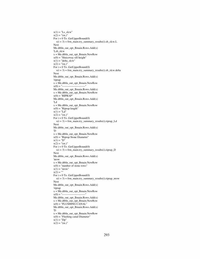
293
x(1) = "Ls_slcw" x(2) = "(m.)" For i = 0 To .GetUpperBound(0) x(i + 3) = frm_main.try_summary_results(i).sb_slcw.L Next Me.dtbln_out_opt_Bmain.Rows.Add(x) 'Lsb_slcw x = Me.dtbln_out_opt_Bmain.NewRow x(0) = "Sluiceway sill height" x(1) = "delta_slcw" x(2) = "(m.)" For i = 0 To .GetUpperBound(0) x(i + 3) = frm_main.try_summary_results(i).sb_slcw.delta Next Me.dtbln_out_opt_Bmain.Rows.Add(x) 'riprap x = Me.dtbln_out_opt_Bmain.NewRow x(0) = "-------------------------" Me.dtbln_out_opt_Bmain.Rows.Add(x) x = Me.dtbln_out_opt_Bmain.NewRow x(0) = "RIPRAP" Me.dtbln_out_opt_Bmain.Rows.Add(x) 'Ld x = Me.dtbln_out_opt_Bmain.NewRow x(0) = "Riprap length" x(1) = "Ld" x(2) = "(m.)" For i = 0 To .GetUpperBound(0) x(i + 3) = frm_main.try_summary_results(i).riprap_Ld Next Me.dtbln_out_opt_Bmain.Rows.Add(x) 'D x = Me.dtbln_out_opt_Bmain.NewRow x(0) = "Riprap Stone Diameter" x(1) = "D" x(2) = "(m.)" For i = 0 To .GetUpperBound(0) x(i + 3) = frm_main.try_summary_results(i).riprap_D Next Me.dtbln_out_opt_Bmain.Rows.Add(x) 'nrow x = Me.dtbln_out_opt_Bmain.NewRow x(0) = "number of stone rows" x(1) = "nrow" x(2) = "" For i = 0 To .GetUpperBound(0) x(i + 3) = frm_main.try_summary_results(i).riprap_nrow Next Me.dtbln_out_opt_Bmain.Rows.Add(x) 'riprap x = Me.dtbln_out_opt_Bmain.NewRow x(0) = "-------------------------" Me.dtbln_out_opt_Bmain.Rows.Add(x) x = Me.dtbln_out_opt_Bmain.NewRow x(0) = "FLUSHING CANAL" Me.dtbln_out_opt_Bmain.Rows.Add(x) 'D x = Me.dtbln_out_opt_Bmain.NewRow x(0) = "Flushing canal Diameter" x(1) = "Dp" x(2) = "(m.)"

294
For i = 0 To .GetUpperBound(0) x(i + 3) = frm_main.try_summary_results(i).flush_Dp Next Me.dtbln_out_opt_Bmain.Rows.Add(x) 'So x = Me.dtbln_out_opt_Bmain.NewRow x(0) = "Flushing canal slope" x(1) = "So" x(2) = "(m.)" For i = 0 To .GetUpperBound(0) x(i + 3) = frm_main.try_summary_results(i).flush_So Next Me.dtbln_out_opt_Bmain.Rows.Add(x) 'L x = Me.dtbln_out_opt_Bmain.NewRow x(0) = "Flushing canal horizantal length" x(1) = "Lh" x(2) = "(m.)" For i = 0 To .GetUpperBound(0) x(i + 3) = frm_main.try_summary_results(i).flush_Lh Next Me.dtbln_out_opt_Bmain.Rows.Add(x) 'SATISFACTORY CRITERIA x = Me.dtbln_out_opt_Bmain.NewRow x(0) = "-------------------------" Me.dtbln_out_opt_Bmain.Rows.Add(x) x = Me.dtbln_out_opt_Bmain.NewRow x(0) = "SEEPAGE" Me.dtbln_out_opt_Bmain.Rows.Add(x) 'Lcr x = Me.dtbln_out_opt_Bmain.NewRow x(0) = "Creep Length" x(1) = "Lcr" x(2) = "(m.)" For i = 0 To .GetUpperBound(0) x(i + 3) = frm_main.try_summary_results(i).Lcr Next Me.dtbln_out_opt_Bmain.Rows.Add(x) 'CH x = Me.dtbln_out_opt_Bmain.NewRow x(0) = "C*H" x(1) = "C*H" x(2) = "(m.)" For i = 0 To .GetUpperBound(0) x(i + 3) = frm_main.try_summary_results(i).CH Next Me.dtbln_out_opt_Bmain.Rows.Add(x) 'seepage Satisfactory x = Me.dtbln_out_opt_Bmain.NewRow x(0) = "Satisfactory" x(1) = "Lcr >= C*H" x(2) = "" For i = 0 To .GetUpperBound(0) x(i + 3) = IIf(frm_main.try_summary_results(i).OK_seepage, "OK", "not OK") Next Me.dtbln_out_opt_Bmain.Rows.Add(x) x = Me.dtbln_out_opt_Bmain.NewRow x(0) = "-------------------------" Me.dtbln_out_opt_Bmain.Rows.Add(x) x = Me.dtbln_out_opt_Bmain.NewRow x(0) = "INTAKE UPLIFT"

295
Me.dtbln_out_opt_Bmain.Rows.Add(x) 'intake FSu_int x = Me.dtbln_out_opt_Bmain.NewRow x(0) = "Intake FS against Uplift" x(1) = "FSu_int" x(2) = "" For i = 0 To .GetUpperBound(0) x(i + 3) = frm_main.try_summary_results(i).FSu_int Next Me.dtbln_out_opt_Bmain.Rows.Add(x) 'satisfactory_FSu_int x = Me.dtbln_out_opt_Bmain.NewRow x(0) = "Satisfactory" x(1) = "FSu_int >= " & frm_main.int_uplift.inp_Fsu_pro x(2) = "" For i = 0 To .GetUpperBound(0) x(i + 3) = IIf(frm_main.try_summary_results(i).OK_uplift_int, "OK", "not OK") Next Me.dtbln_out_opt_Bmain.Rows.Add(x) x = Me.dtbln_out_opt_Bmain.NewRow x(0) = "-------------------------" Me.dtbln_out_opt_Bmain.Rows.Add(x) x = Me.dtbln_out_opt_Bmain.NewRow x(0) = "SPILLWAY UPLIFT" Me.dtbln_out_opt_Bmain.Rows.Add(x) 'FSu_splw x = Me.dtbln_out_opt_Bmain.NewRow x(0) = "Spillway FS against Uplift" x(1) = "FSu_splw" x(2) = "" For i = 0 To .GetUpperBound(0) x(i + 3) = frm_main.try_summary_results(i).FSu_splw Next Me.dtbln_out_opt_Bmain.Rows.Add(x) 'satisfactory_FSu_splw x = Me.dtbln_out_opt_Bmain.NewRow x(0) = "Satisfactory" x(1) = "FSu_splw >= " & frm_main.splw_uplift.inp_Fsu_pro x(2) = "" For i = 0 To .GetUpperBound(0) x(i + 3) = IIf(frm_main.try_summary_results(i).OK_uplift_splw, "OK", "not OK") Next Me.dtbln_out_opt_Bmain.Rows.Add(x) x = Me.dtbln_out_opt_Bmain.NewRow x(0) = "-------------------------" Me.dtbln_out_opt_Bmain.Rows.Add(x) x = Me.dtbln_out_opt_Bmain.NewRow x(0) = "SLUICEWAY UPLIFT" Me.dtbln_out_opt_Bmain.Rows.Add(x) 'FSu_slcw x = Me.dtbln_out_opt_Bmain.NewRow x(0) = "Sluiceway FS against Uplift" x(1) = "FSu_slcw" x(2) = "" For i = 0 To .GetUpperBound(0) x(i + 3) = frm_main.try_summary_results(i).FSu_slcw Next Me.dtbln_out_opt_Bmain.Rows.Add(x) 'satisfactory_FSu_slcw x = Me.dtbln_out_opt_Bmain.NewRow x(0) = "Satisfactory"

296
x(1) = "FSu_slcw >= " & frm_main.slcw_uplift.inp_Fsu_pro x(2) = "" For i = 0 To .GetUpperBound(0) x(i + 3) = IIf(frm_main.try_summary_results(i).OK_uplift_slcw, "OK", "not OK") Next Me.dtbln_out_opt_Bmain.Rows.Add(x) x = Me.dtbln_out_opt_Bmain.NewRow x(0) = "-------------------------" Me.dtbln_out_opt_Bmain.Rows.Add(x) x = Me.dtbln_out_opt_Bmain.NewRow x(0) = "BODY+APRON SLIDING" Me.dtbln_out_opt_Bmain.Rows.Add(x) 'FSs x = Me.dtbln_out_opt_Bmain.NewRow x(0) = "Body+Apron FS against Sliding" x(1) = "FSs" x(2) = "" For i = 0 To .GetUpperBound(0) x(i + 3) = frm_main.try_summary_results(i).FSs Next Me.dtbln_out_opt_Bmain.Rows.Add(x) 'satisfactory_FSs x = Me.dtbln_out_opt_Bmain.NewRow x(0) = "Satisfactory" x(1) = "FSs >= " & frm_main.stab_slide_overt.input_Fs_pro.FSs x(2) = "" For i = 0 To .GetUpperBound(0) x(i + 3) = IIf(frm_main.try_summary_results(i).OK_s, "OK", "not OK") Next Me.dtbln_out_opt_Bmain.Rows.Add(x) x = Me.dtbln_out_opt_Bmain.NewRow x(0) = "-------------------------" Me.dtbln_out_opt_Bmain.Rows.Add(x) x = Me.dtbln_out_opt_Bmain.NewRow x(0) = "BODY+APRON SHEAR&SLIDING" Me.dtbln_out_opt_Bmain.Rows.Add(x) 'FSss x = Me.dtbln_out_opt_Bmain.NewRow x(0) = "Body+Apron FS against Shear&Sliding" x(1) = "FSss" x(2) = "" For i = 0 To .GetUpperBound(0) x(i + 3) = frm_main.try_summary_results(i).FSss Next Me.dtbln_out_opt_Bmain.Rows.Add(x) 'satisfactory_FSss x = Me.dtbln_out_opt_Bmain.NewRow x(0) = "Satisfactory" x(1) = "FSss >= " & frm_main.stab_slide_overt.input_Fs_pro.FSss x(2) = "" For i = 0 To .GetUpperBound(0) x(i + 3) = IIf(frm_main.try_summary_results(i).OK_ss, "OK", "not OK") Next Me.dtbln_out_opt_Bmain.Rows.Add(x) x = Me.dtbln_out_opt_Bmain.NewRow x(0) = "-------------------------" Me.dtbln_out_opt_Bmain.Rows.Add(x) x = Me.dtbln_out_opt_Bmain.NewRow x(0) = "BODY OVERTURNING (full u/s no tw)" Me.dtbln_out_opt_Bmain.Rows.Add(x) 'FSo

297
x = Me.dtbln_out_opt_Bmain.NewRow x(0) = "Body FS against Overturning" x(1) = "FSo" x(2) = "" For i = 0 To .GetUpperBound(0) x(i + 3) = frm_main.try_summary_results(i).MVoheel.FSo Next Me.dtbln_out_opt_Bmain.Rows.Add(x) 'satisfactory_FSo x = Me.dtbln_out_opt_Bmain.NewRow x(0) = "Satisfactory (full u/s no tw)" x(1) = "FSo >= " & frm_main.stab_slide_overt.input_Fs_pro.FSo x(2) = "" For i = 0 To .GetUpperBound(0) x(i + 3) = IIf(frm_main.try_summary_results(i).MVoheel.OK_o, "OK", "not OK") Next Me.dtbln_out_opt_Bmain.Rows.Add(x) x = Me.dtbln_out_opt_Bmain.NewRow Me.dtbln_out_opt_Bmain.Rows.Add(x) 'Vtoe x = Me.dtbln_out_opt_Bmain.NewRow x(0) = "Base pressure at toe" x(1) = "Vtoe" x(2) = "(kN/m2)" For i = 0 To .GetUpperBound(0) x(i + 3) = frm_main.try_summary_results(i).MVoheel.Vtoe Next Me.dtbln_out_opt_Bmain.Rows.Add(x) 'Vheel x = Me.dtbln_out_opt_Bmain.NewRow x(0) = "Base pressure at heel" x(1) = "Vtoe" x(2) = "(kN/m2)" For i = 0 To .GetUpperBound(0) x(i + 3) = frm_main.try_summary_results(i).MVoheel.Vheel Next Me.dtbln_out_opt_Bmain.Rows.Add(x) 'Vmax satisfactory x = Me.dtbln_out_opt_Bmain.NewRow x(0) = "Satisfactory Max. base Pressure " x(1) = "Vmax <= " & frm_main.stab_slide_overt.input_Fs_pro.Vmax x(2) = "" For i = 0 To .GetUpperBound(0) x(i + 3) = IIf(frm_main.try_summary_results(i).MVoheel.OK_vmax, "OK", "not OK") Next Me.dtbln_out_opt_Bmain.Rows.Add(x) 'Vmin satisfactory x = Me.dtbln_out_opt_Bmain.NewRow x(0) = "Satisfactory Min. base Pressure " x(1) = "Vmin >= " & frm_main.stab_slide_overt.input_Fs_pro.Vmin x(2) = "" For i = 0 To .GetUpperBound(0) x(i + 3) = IIf(frm_main.try_summary_results(i).MVoheel.OK_vmin, "OK", "not OK") Next Me.dtbln_out_opt_Bmain.Rows.Add(x) x = Me.dtbln_out_opt_Bmain.NewRow x(0) = "-------------------------" Me.dtbln_out_opt_Bmain.Rows.Add(x) x = Me.dtbln_out_opt_Bmain.NewRow x(0) = "BODY OVERTURNING (empty reserv. wrt heel)" Me.dtbln_out_opt_Bmain.Rows.Add(x)

298
'FSo empty reserv x = Me.dtbln_out_opt_Bmain.NewRow x(0) = "Body FS against Overturning" x(1) = "FSo" x(2) = "" For i = 0 To .GetUpperBound(0) x(i + 3) = frm_main.try_summary_results(i).MVoheel_eu.FSo Next Me.dtbln_out_opt_Bmain.Rows.Add(x) 'satisfactory_FSo x = Me.dtbln_out_opt_Bmain.NewRow x(0) = "Satisfactory (empty res.wrt heel)" x(1) = "FSo >= " & frm_main.stab_slide_overt.input_Fs_pro.FSo x(2) = "" For i = 0 To .GetUpperBound(0) x(i + 3) = IIf(frm_main.try_summary_results(i).MVoheel_eu.OK_o, "OK", "not OK") Next Me.dtbln_out_opt_Bmain.Rows.Add(x) x = Me.dtbln_out_opt_Bmain.NewRow Me.dtbln_out_opt_Bmain.Rows.Add(x) 'Vtoe x = Me.dtbln_out_opt_Bmain.NewRow x(0) = "Base pressure at toe" x(1) = "Vtoe" x(2) = "(kN/m2)" For i = 0 To .GetUpperBound(0) x(i + 3) = frm_main.try_summary_results(i).MVoheel_eu.Vtoe Next Me.dtbln_out_opt_Bmain.Rows.Add(x) 'Vheel x = Me.dtbln_out_opt_Bmain.NewRow x(0) = "Base pressure at heel" x(1) = "Vtoe" x(2) = "(kN/m2)" For i = 0 To .GetUpperBound(0) x(i + 3) = frm_main.try_summary_results(i).MVoheel_eu.Vheel Next Me.dtbln_out_opt_Bmain.Rows.Add(x) 'Vmax satisfactory x = Me.dtbln_out_opt_Bmain.NewRow x(0) = "Satisfactory Max. base Pressure " x(1) = "Vmax <= " & frm_main.stab_slide_overt.input_Fs_pro.Vmax x(2) = "" For i = 0 To .GetUpperBound(0) x(i + 3) = IIf(frm_main.try_summary_results(i).MVoheel_eu.OK_vmax, "OK", "not OK") Next Me.dtbln_out_opt_Bmain.Rows.Add(x) 'Vmin satisfactory x = Me.dtbln_out_opt_Bmain.NewRow x(0) = "Satisfactory Min. base Pressure " x(1) = "Vmin >= " & frm_main.stab_slide_overt.input_Fs_pro.Vmin x(2) = "" For i = 0 To .GetUpperBound(0) x(i + 3) = IIf(frm_main.try_summary_results(i).MVoheel_eu.OK_vmin, "OK", "not OK") Next Me.dtbln_out_opt_Bmain.Rows.Add(x) x = Me.dtbln_out_opt_Bmain.NewRow x(0) = "-------------------------" Me.dtbln_out_opt_Bmain.Rows.Add(x) x = Me.dtbln_out_opt_Bmain.NewRow x(0) = "BODY OVERTURNING (empty reserv. wrt toe)"

299
Me.dtbln_out_opt_Bmain.Rows.Add(x) 'FSo empty reserv wrt toe x = Me.dtbln_out_opt_Bmain.NewRow x(0) = "Body FS against Overturning" x(1) = "FSo" x(2) = "" For i = 0 To .GetUpperBound(0) x(i + 3) = frm_main.try_summary_results(i).MVotoe_eu.FSo Next Me.dtbln_out_opt_Bmain.Rows.Add(x) 'satisfactory_FSo x = Me.dtbln_out_opt_Bmain.NewRow x(0) = "Satisfactory (empty res.wrt toe)" x(1) = "FSo >= " & frm_main.stab_slide_overt.input_Fs_pro.FSo x(2) = "" For i = 0 To .GetUpperBound(0) x(i + 3) = IIf(frm_main.try_summary_results(i).MVotoe_eu.OK_o, "OK", "not OK") Next Me.dtbln_out_opt_Bmain.Rows.Add(x) x = Me.dtbln_out_opt_Bmain.NewRow Me.dtbln_out_opt_Bmain.Rows.Add(x) 'Vtoe x = Me.dtbln_out_opt_Bmain.NewRow x(0) = "Base pressure at toe" x(1) = "Vtoe" x(2) = "(kN/m2)" For i = 0 To .GetUpperBound(0) x(i + 3) = frm_main.try_summary_results(i).MVotoe_eu.Vtoe Next Me.dtbln_out_opt_Bmain.Rows.Add(x) 'Vheel x = Me.dtbln_out_opt_Bmain.NewRow x(0) = "Base pressure at heel" x(1) = "Vtoe" x(2) = "(kN/m2)" For i = 0 To .GetUpperBound(0) x(i + 3) = frm_main.try_summary_results(i).MVotoe_eu.Vheel Next Me.dtbln_out_opt_Bmain.Rows.Add(x) 'Vmax satisfactory x = Me.dtbln_out_opt_Bmain.NewRow x(0) = "Satisfactory Max. base Pressure " x(1) = "Vmax <= " & frm_main.stab_slide_overt.input_Fs_pro.Vmax x(2) = "" For i = 0 To .GetUpperBound(0) x(i + 3) = IIf(frm_main.try_summary_results(i).MVotoe_eu.OK_vmax, "OK", "not OK") Next Me.dtbln_out_opt_Bmain.Rows.Add(x) 'Vmin satisfactory x = Me.dtbln_out_opt_Bmain.NewRow x(0) = "Satisfactory Min. base Pressure " x(1) = "Vmin >= " & frm_main.stab_slide_overt.input_Fs_pro.Vmin x(2) = "" For i = 0 To .GetUpperBound(0) x(i + 3) = IIf(frm_main.try_summary_results(i).MVotoe_eu.OK_vmin, "OK", "not OK") Next Me.dtbln_out_opt_Bmain.Rows.Add(x) x = Me.dtbln_out_opt_Bmain.NewRow x(0) = "-------------------------" Me.dtbln_out_opt_Bmain.Rows.Add(x) x = Me.dtbln_out_opt_Bmain.NewRow

300
x(0) = "SIDEWALLS (Spillway Side)" Me.dtbln_out_opt_Bmain.Rows.Add(x) 'FSs x = Me.dtbln_out_opt_Bmain.NewRow x(0) = "Sidewalls FS against Sliding" x(1) = "FSs" x(2) = "" For i = 0 To .GetUpperBound(0) x(i + 3) = frm_main.try_summary_results(i).FSs_sw_splw Next Me.dtbln_out_opt_Bmain.Rows.Add(x) 'satisfactory_FSs x = Me.dtbln_out_opt_Bmain.NewRow x(0) = "Satisfactory" x(1) = "FSs >= " & frm_main.stab_slide_overt.input_Fs_pro.FSs_sw x(2) = "" For i = 0 To .GetUpperBound(0) x(i + 3) = IIf(frm_main.try_summary_results(i).OK_s_sw_splw, "OK", "not OK") Next Me.dtbln_out_opt_Bmain.Rows.Add(x) x = Me.dtbln_out_opt_Bmain.NewRow Me.dtbln_out_opt_Bmain.Rows.Add(x) 'Vtoe x = Me.dtbln_out_opt_Bmain.NewRow x(0) = "Base pressure at toe" x(1) = "Vtoe" x(2) = "(kN/m2)" For i = 0 To .GetUpperBound(0) x(i + 3) = frm_main.try_summary_results(i).MVo_sw_splw.Vtoe Next Me.dtbln_out_opt_Bmain.Rows.Add(x) 'Vheel x = Me.dtbln_out_opt_Bmain.NewRow x(0) = "Base pressure at heel" x(1) = "Vtoe" x(2) = "(kN/m2)" For i = 0 To .GetUpperBound(0) x(i + 3) = frm_main.try_summary_results(i).MVo_sw_splw.Vheel Next Me.dtbln_out_opt_Bmain.Rows.Add(x) 'Vmax satisfactory x = Me.dtbln_out_opt_Bmain.NewRow x(0) = "Satisfactory Max. base Pressure " x(1) = "Vmax <= " & frm_main.stab_slide_overt.input_Fs_pro.Vmax_sw x(2) = "" For i = 0 To .GetUpperBound(0) x(i + 3) = IIf(frm_main.try_summary_results(i).MVo_sw_splw.OK_vmax, "OK", "not OK") Next Me.dtbln_out_opt_Bmain.Rows.Add(x) 'Vmin satisfactory x = Me.dtbln_out_opt_Bmain.NewRow x(0) = "Satisfactory Min. base Pressure " x(1) = "Vmin >= " & frm_main.stab_slide_overt.input_Fs_pro.Vmin_sw x(2) = "" For i = 0 To .GetUpperBound(0) x(i + 3) = IIf(frm_main.try_summary_results(i).MVo_sw_splw.OK_vmin, "OK", "not OK") Next Me.dtbln_out_opt_Bmain.Rows.Add(x) x = Me.dtbln_out_opt_Bmain.NewRow x(0) = "-------------------------" Me.dtbln_out_opt_Bmain.Rows.Add(x)

301
x = Me.dtbln_out_opt_Bmain.NewRow x(0) = "SIDEWALLS (Sluiceway Side)" Me.dtbln_out_opt_Bmain.Rows.Add(x) 'FSo empty reserv wrt toe x = Me.dtbln_out_opt_Bmain.NewRow x(0) = "Sidewalls FS against Sliding" x(1) = "FSs" x(2) = "" For i = 0 To .GetUpperBound(0) x(i + 3) = frm_main.try_summary_results(i).FSs_sw_slcw Next Me.dtbln_out_opt_Bmain.Rows.Add(x) 'satisfactory_FSo x = Me.dtbln_out_opt_Bmain.NewRow x(0) = "Satisfactory" x(1) = "FSs >= " & frm_main.stab_slide_overt.input_Fs_pro.FSs_sw x(2) = "" For i = 0 To .GetUpperBound(0) x(i + 3) = IIf(frm_main.try_summary_results(i).OK_s_sw_slcw, "OK", "not OK") Next Me.dtbln_out_opt_Bmain.Rows.Add(x) x = Me.dtbln_out_opt_Bmain.NewRow Me.dtbln_out_opt_Bmain.Rows.Add(x) 'Vtoe x = Me.dtbln_out_opt_Bmain.NewRow x(0) = "Base pressure at toe" x(1) = "Vtoe" x(2) = "(kN/m2)" For i = 0 To .GetUpperBound(0) x(i + 3) = frm_main.try_summary_results(i).MVo_sw_slcw.Vtoe Next Me.dtbln_out_opt_Bmain.Rows.Add(x) 'Vheel x = Me.dtbln_out_opt_Bmain.NewRow x(0) = "Base pressure at heel" x(1) = "Vtoe" x(2) = "(kN/m2)" For i = 0 To .GetUpperBound(0) x(i + 3) = frm_main.try_summary_results(i).MVo_sw_slcw.Vheel Next Me.dtbln_out_opt_Bmain.Rows.Add(x) 'Vmax satisfactory x = Me.dtbln_out_opt_Bmain.NewRow x(0) = "Satisfactory Max. base Pressure " x(1) = "Vmax <= " & frm_main.stab_slide_overt.input_Fs_pro.Vmax_sw x(2) = "" For i = 0 To .GetUpperBound(0) x(i + 3) = IIf(frm_main.try_summary_results(i).MVo_sw_slcw.OK_vmax, "OK", "not OK") Next Me.dtbln_out_opt_Bmain.Rows.Add(x) 'Vmin satisfactory x = Me.dtbln_out_opt_Bmain.NewRow x(0) = "Satisfactory Min. base Pressure " x(1) = "Vmin >= " & frm_main.stab_slide_overt.input_Fs_pro.Vmin_sw x(2) = "" For i = 0 To .GetUpperBound(0) x(i + 3) = IIf(frm_main.try_summary_results(i).MVo_sw_slcw.OK_vmin, "OK", "not OK") Next Me.dtbln_out_opt_Bmain.Rows.Add(x) End With End Sub

302
#End Region #Region "Printout procedures" Private Sub print_preview(ByVal dtable As DataTable) Me.DataGridEx2.PageSettings = CustomControls.PageSetup.PageSettings Me.DataGridEx2.PrintPreview(Nothing, dtable, CType(Me.BindingContext(Me.DataGridEx2.DataSource), CurrencyManager), 25, "Do you wish to continue?", " ") End Sub Private Sub print_out(ByVal dtable As DataTable) Me.DataGridEx2.PageSettings = CustomControls.PageSetup.PageSettings Me.DataGridEx2.Print(Nothing, dtable, CType(Me.BindingContext(Me.DataGridEx2.DataSource), CurrencyManager), " ") End Sub #End Region #End Region Private Sub MenuItem1_Click(ByVal sender As System.Object, ByVal e As System.EventArgs) Handles MenuItem1.Click Me.DataGridEx2.CaptionText = "Intake Water Surface Profile Table:" Me.DataGridEx2.AdjustColumnWidths(Me.dtbln_out_int) Me.DataGridEx2.DataSource = Me.dtbln_out_int End Sub Private Sub MenuItem2_Click(ByVal sender As System.Object, ByVal e As System.EventArgs) Handles MenuItem2.Click Me.DataGridEx2.CaptionText = "Intake Computations Summary Table:" Me.DataGridEx2.AdjustColumnWidths(Me.dtbln_out_int2) Me.DataGridEx2.DataSource = Me.dtbln_out_int2 End Sub Private Sub MenuItem4_Click(ByVal sender As Object, ByVal e As System.EventArgs) Handles MenuItem4.Click frm_outputs.chart_no = 0 Dim frm_graph As New frm_charts() frm_graph.Show() End Sub Private Sub GroupBox1_Enter(ByVal sender As System.Object, ByVal e As System.EventArgs) Handles GroupBox1.Enter End Sub Private Sub MenuItem12_Click(ByVal sender As System.Object, ByVal e As System.EventArgs) End Sub Private Sub MenuItem10_Click(ByVal sender As System.Object, ByVal e As System.EventArgs) Handles MenuItem10.Click Me.DataGridEx2.CaptionText = "Spillway - Sluiceway Discharges Table:" Me.DataGridEx2.AdjustColumnWidths(Me.dtbln_out_splw_slcw) Me.DataGridEx2.DataSource = Me.dtbln_out_splw_slcw End Sub Private Sub MenuItem11_Click(ByVal sender As System.Object, ByVal e As System.EventArgs) Handles MenuItem11.Click Me.DataGridEx2.CaptionText = "Energy Dissipators Results Table:" Me.DataGridEx2.AdjustColumnWidths(Me.dtbln_out_energydis) Me.DataGridEx2.DataSource = Me.dtbln_out_energydis End Sub Private Sub MenuItem3_Click(ByVal sender As System.Object, ByVal e As System.EventArgs) Handles MenuItem3.Click Me.print_preview(Me.DataGridEx2.DataSource) End Sub Private Sub MenuItem5_Click(ByVal sender As System.Object, ByVal e As System.EventArgs) Handles MenuItem5.Click Me.print_out(Me.DataGridEx2.DataSource) Me.DataGridEx2.PageSettings = CustomControls.PageSetup.PageSettings End Sub Private Sub MenuItem6_Click(ByVal sender As System.Object, ByVal e As System.EventArgs) Handles MenuItem6.Click

303
Me.DataGridEx2.CaptionText = "Seepage Computations Results Table:" Me.DataGridEx2.AdjustColumnWidths(Me.dtbln_out_seepage) Me.DataGridEx2.DataSource = Me.dtbln_out_seepage End Sub Private Sub MenuItem7_Click(ByVal sender As System.Object, ByVal e As System.EventArgs) Handles MenuItem7.Click End Sub Private Sub MenuItem16_Click(ByVal sender As System.Object, ByVal e As System.EventArgs) Handles MenuItem16.Click Me.DataGridEx2.PageSetup() Me.DataGridEx2.PageSettings = CustomControls.PageSetup.PageSettings End Sub Private Sub MenuItem17_Click(ByVal sender As System.Object, ByVal e As System.EventArgs) Handles MenuItem17.Click frm_outputs.chart_no = 1 Dim frm_graph As New frm_charts() frm_graph.Show() End Sub Private Sub MenuItem18_Click(ByVal sender As System.Object, ByVal e As System.EventArgs) Handles MenuItem18.Click frm_outputs.chart_no = 2 Dim frm_graph As New frm_charts() frm_graph.Show() End Sub Private Sub MenuItem19_Click(ByVal sender As System.Object, ByVal e As System.EventArgs) Handles MenuItem19.Click Me.DataGridEx2.CaptionText = "Intake Stability against Uplift Results Table:" Me.DataGridEx2.AdjustColumnWidths(Me.dtbln_out_stab_upl_int) Me.DataGridEx2.DataSource = Me.dtbln_out_stab_upl_int End Sub Private Sub MenuItem20_Click(ByVal sender As System.Object, ByVal e As System.EventArgs) Handles MenuItem20.Click Me.DataGridEx2.CaptionText = "Spillway Stability against Uplift Results Table:" Me.DataGridEx2.AdjustColumnWidths(Me.dtbln_out_stab_upl_splw) Me.DataGridEx2.DataSource = Me.dtbln_out_stab_upl_splw End Sub Private Sub MenuItem21_Click(ByVal sender As System.Object, ByVal e As System.EventArgs) Handles MenuItem21.Click Me.DataGridEx2.CaptionText = "Sluiceway Stability against Uplift Results Table:" Me.DataGridEx2.AdjustColumnWidths(Me.dtbln_out_stab_upl_slcw) Me.DataGridEx2.DataSource = Me.dtbln_out_stab_upl_slcw End Sub Private Sub MenuItem9_Click(ByVal sender As System.Object, ByVal e As System.EventArgs) Handles MenuItem9.Click Me.DataGridEx2.CaptionText = "Spillway Body Stability against Overturning Results Table:" Me.DataGridEx2.AdjustColumnWidths(Me.dtbln_out_stab_overt_splw) Me.DataGridEx2.DataSource = Me.dtbln_out_stab_overt_splw End Sub Private Sub MenuItem23_Click(ByVal sender As System.Object, ByVal e As System.EventArgs) Handles MenuItem23.Click DataSetExport.Export(Me.DataGridEx2.DataSource) End Sub Private Sub MenuItem24_Click(ByVal sender As System.Object, ByVal e As System.EventArgs) Handles MenuItem24.Click DataSetExport.SendEMail(Me.DataGridEx2.DataSource) End Sub Private Sub MenuItem13_Click(ByVal sender As System.Object, ByVal e As System.EventArgs) Handles MenuItem13.Click Me.DataGridEx2.CaptionText = "Spillway Body+Apron Stability against Sliding Results Table (Full u/s no Tailwater):" Me.DataGridEx2.AdjustColumnWidths(Me.dtbln_out_stab_slide_splw)

304
Me.DataGridEx2.DataSource = Me.dtbln_out_stab_slide_splw End Sub Private Sub MenuItem25_Click(ByVal sender As System.Object, ByVal e As System.EventArgs) Handles MenuItem25.Click Me.DataGridEx2.CaptionText = "Spillway Body Stability against Overturning Results Table (Empty reservoir wrt Toe):" Me.DataGridEx2.AdjustColumnWidths(Me.dtbln_out_stab_overt_splw_er_wrt_toe) Me.DataGridEx2.DataSource = Me.dtbln_out_stab_overt_splw_er_wrt_toe End Sub Private Sub MenuItem26_Click(ByVal sender As System.Object, ByVal e As System.EventArgs) Handles MenuItem26.Click Me.DataGridEx2.CaptionText = "Spillway Body Stability against Overturning Results Table (Empty reservoir wrt Heel):" Me.DataGridEx2.AdjustColumnWidths(Me.dtbln_out_stab_overt_splw_er_wrt_heel) Me.DataGridEx2.DataSource = Me.dtbln_out_stab_overt_splw_er_wrt_heel End Sub Private Sub MenuItem27_Click(ByVal sender As System.Object, ByVal e As System.EventArgs) Handles MenuItem27.Click Me.DataGridEx2.CaptionText = "Crest Elevation of u/s Levees Results Table" Me.DataGridEx2.AdjustColumnWidths(Me.dtbln_out_levees) Me.DataGridEx2.DataSource = Me.dtbln_out_levees End Sub Private Sub MenuItem28_Click(ByVal sender As System.Object, ByVal e As System.EventArgs) Handles MenuItem28.Click frm_outputs.chart_no = 3 Dim frm_graph As New frm_charts() frm_graph.Show() End Sub Private Sub MenuItem29_Click(ByVal sender As System.Object, ByVal e As System.EventArgs) Handles MenuItem29.Click Me.DataGridEx2.CaptionText = "Riprap Design Results Table:" Me.DataGridEx2.AdjustColumnWidths(Me.dtbln_out_riprap) Me.DataGridEx2.DataSource = Me.dtbln_out_riprap End Sub Private Sub MenuItem30_Click(ByVal sender As System.Object, ByVal e As System.EventArgs) Handles MenuItem30.Click Me.DataGridEx2.CaptionText = "Flushing Canal Design Results Table:" Me.DataGridEx2.AdjustColumnWidths(Me.dtbln_out_flush) Me.DataGridEx2.DataSource = Me.dtbln_out_flush End Sub Private Sub MenuItem31_Click(ByVal sender As System.Object, ByVal e As System.EventArgs) Handles MenuItem31.Click Me.DataGridEx2.CaptionText = "WSP for optimum width Results Table:" Me.DataGridEx2.AdjustColumnWidths(Me.dtbln_out_div_wsp) Me.DataGridEx2.DataSource = Me.dtbln_out_div_wsp End Sub Private Sub MenuItem32_Click(ByVal sender As System.Object, ByVal e As System.EventArgs) Handles MenuItem32.Click Me.DataGridEx2.CaptionText = "Cost analysis for different canal widths Summary Table:" Me.DataGridEx2.AdjustColumnWidths(Me.dtbln_out_div_summary) Me.DataGridEx2.DataSource = Me.dtbln_out_div_summary End Sub Private Sub MenuItem33_Click(ByVal sender As System.Object, ByVal e As System.EventArgs) Handles MenuItem33.Click frm_outputs.chart_no = 4 Dim frm_graph As New frm_charts() frm_graph.Show() End Sub Private Sub MenuItem34_Click(ByVal sender As System.Object, ByVal e As System.EventArgs) Handles MenuItem34.Click frm_outputs.chart_no = 5

305
Dim frm_graph As New frm_charts() frm_graph.Show() End Sub Private Sub MenuItem42_Click(ByVal sender As System.Object, ByVal e As System.EventArgs) Handles MenuItem42.Click frm_outputs.chart_no = 6 Dim frm_graph As New frm_charts() frm_graph.Show() End Sub Private Sub MenuItem41_Click(ByVal sender As System.Object, ByVal e As System.EventArgs) Handles MenuItem41.Click Me.DataGridEx2.CaptionText = "Summary of the Optimization Tries Results Table:" Me.DataGridEx2.AdjustColumnWidths(Me.dtbln_out_opt_Bmain) Me.DataGridEx2.DataSource = Me.dtbln_out_opt_Bmain End Sub Private Sub MenuItem43_Click(ByVal sender As System.Object, ByVal e As System.EventArgs) Handles MenuItem43.Click Me.DataGridEx2.CaptionText = "Costs of the Structures Results Table:" Me.DataGridEx2.AdjustColumnWidths(Me.dtbln_out_costs) Me.DataGridEx2.DataSource = Me.dtbln_out_costs End Sub Private Sub MenuItem35_Click(ByVal sender As System.Object, ByVal e As System.EventArgs) Handles MenuItem35.Click Me.DataGridEx2.CaptionText = "Sidewalls Stability against Sliding Results Table:" Me.DataGridEx2.AdjustColumnWidths(Me.dtbln_out_sw_splw_slide) Me.DataGridEx2.DataSource = Me.dtbln_out_sw_splw_slide End Sub End Class '*---------------------------------------------------------------------------------------------------------------------------------* '| END OF FORM-4 | '*---------------------------------------------------------------------------------------------------------------------------------* '*---------------------------------------------------------------------------------------------------------------------------------* '| FORM-11 : Form11.vb | '*---------------------------------------------------------------------------------------------------------------------------------* Imports scpl2 Imports dweir_code.General_Hydraulic_Functions Imports System.Math Public Class frm_charts Inherits System.Windows.Forms.Form #Region " Windows Form Designer generated code " Public Sub New() MyBase.New() 'This call is required by the Windows Form Designer. InitializeComponent() 'Add any initialization after the InitializeComponent() call End Sub 'Form overrides dispose to clean up the component list. Protected Overloads Overrides Sub Dispose(ByVal disposing As Boolean) If disposing Then If Not (components Is Nothing) Then components.Dispose() End If End If MyBase.Dispose(disposing) End Sub 'Required by the Windows Form Designer Private components As System.ComponentModel.IContainer 'NOTE: The following procedure is required by the Windows Form Designer 'It can be modified using the Windows Form Designer.

306
'Do not modify it using the code editor. ‘This part of code is generated automatically. Details are hidden. #End Region Const serie_size As Integer = 20 'max serie sixe to show in a graph together 'graphical elements (series= 2 of them forms a serie; because they are related eachother; line rep and point rep) Private series As New Collection() Private xsec_int(11) As xsec_hyd Private Sub frm_charts_Load(ByVal sender As System.Object, ByVal e As System.EventArgs) Handles MyBase.Load Me.load_chart_data(frm_outputs.chart_no) End Sub #Region "general chart procedures" Private Sub add_plot(ByVal x() As Single, ByVal y() As Single, ByVal lcolor As Color, ByVal serie_name As String) Dim lp As New LinePlot(New ArrayAdapter(x, y)) 'to plot line Dim pp As New PointPlot(New ArrayAdapter(x, y)) 'to plot point With Me.chart lp.Pen = New Pen(lcolor, 2) pp.Marker.Type = MarkerType.Cross1 pp.Marker.Pen = New Pen(lcolor, 5) lp.Label = serie_name pp.Label = serie_name & " points" End With series.Add(lp, serie_name & "_l") series.Add(pp, serie_name & "_p") End Sub Private Sub remove_plot(ByVal serie_name As String) Me.chart.remove(series.Item(serie_name & "_l")) Me.chart.remove(series.Item(serie_name & "_p")) series.Remove(serie_name & "_l") series.Remove(serie_name & "_p") End Sub Private Sub load_default_chart_pro() 'default chart properties With Me.chart .MajorGridPen.DashStyle = Drawing.Drawing2D.DashStyle.Dash .MajorGridPen.Color = Color.Gray .MinorGridPen.Color = Color.LightGray .MinorGridPen.DashStyle = Drawing.Drawing2D.DashStyle.Dot .TitleFont = New Font("Arail", 9, FontStyle.Bold, GraphicsUnit.Point) .XAxis1.LabelFont = New Font("Arial", 8, FontStyle.Italic, GraphicsUnit.Point) .YAxis1.LabelFont = New Font("Arial", 8, FontStyle.Italic, GraphicsUnit.Point) .XAxis1.GridDetail = Axis.GridType.None .YAxis1.GridDetail = Axis.GridType.None .LegendAttachTo(XAxisPosition.Bottom, YAxisPosition.Right) .HorizontalEdgeLegendPlacement = Legend.Placement.Inside .VerticalEdgeLegendPlacement = Legend.Placement.Inside .LegendBorderStyle = Legend.BorderType.Line .ShowLegend = True .Refresh() 'refresh the graph options to all checked Me.MenuItem2.Checked = True Me.MenuItem5.Checked = False Me.MenuItem6.Checked = False End With End Sub Private Sub show_charts(ByVal title As String, ByVal xaxis As String, ByVal yaxis As String) Dim i As Integer 'reset chart firstly 'by this algorithm, everytime, chart is rescaled according to the existing plot data

307
Me.chart.Clear() For i = 1 To series.Count 'for collections indexs starts from 1 Me.chart.Add(series.Item(i)) Next 'refresh default view everytime... load_default_chart_pro() ' every time to show chart titles Me.chart.Title = title Me.chart.XAxis1.Label = xaxis Me.chart.YAxis1.Label = yaxis Me.chart.Refresh() End Sub Private Sub load_chart_data(ByVal chart_no As Byte) Select Case chart_no Case 0 'intake water surface profile load_intake_wsp() Case 1 'K versus discharge graph (spillw sluiceway)Rating curve load_K_versus_Q() Case 2 'seepage load_seepage_path() Case 3 'crest el. of levees load_levees_wsp() Case 4 load_div_wsp() Case 5 load_div_costs() Case 6 load_opt_Bmain_costs() End Select End Sub #End Region #Region "intake wsp" Private Sub add_int_plot_Kb() Dim i As Integer Dim xx(11), yy(11) As Single For i = 0 To xsec_int.GetUpperBound(0) xx(i) = xsec_int(i).km_xsec_p yy(i) = xsec_int(i).Kb_pro Next Me.add_plot(xx, yy, Color.Brown, "Ground surface") End Sub Private Sub add_int_plot_HGL() Dim i As Integer Dim xx(11), yy(11) As Single For i = 0 To xsec_int.GetUpperBound(0) xx(i) = xsec_int(i).km_xsec_p yy(i) = xsec_int(i).Hgl_pro Next Me.add_plot(xx, yy, Color.Blue, "HGL") End Sub Private Sub add_int_plot_EGL() Dim i As Integer Dim xx(11), yy(11) As Single For i = 0 To xsec_int.GetUpperBound(0) xx(i) = xsec_int(i).km_xsec_p yy(i) = xsec_int(i).Egl_pro Next Me.add_plot(xx, yy, Color.Green, "EGL") End Sub Private Sub load_intake_wsp() If Not (IsNothing(frm_main.intake_des)) Then 'if intake computations were made or not

308
Me.ToolBarButton2.DropDownMenu = Me.mnu_graph_int 'readjust xsec for plot With frm_main.intake_des xsec_int(0) = .xsec_pro(0) xsec_int(1) = .xsec_pro(1) xsec_int(2) = New xsec_hyd(.xsec_pro(1)) xsec_int(2).km_xsec_p = .xsec_pro(2).km_xsec_p xsec_int(3) = .xsec_pro(2) xsec_int(4) = .xsec_pro(3) xsec_int(5) = .xsec_pro(4) xsec_int(6) = .xsec_pro(5) xsec_int(7) = .xsec_pro(6) xsec_int(8) = New xsec_hyd(.xsec_pro(6)) xsec_int(8).km_xsec_p = .xsec_pro(7).km_xsec_p xsec_int(9) = .xsec_pro(7) xsec_int(10) = .xsec_pro(8) xsec_int(11) = New xsec_hyd(.xsec_pro(8)) xsec_int(11).km_xsec_p -= 1 End With Me.add_int_plot_Kb() Me.add_int_plot_HGL() Me.add_int_plot_EGL() Me.show_charts("Intake Water Surface Elevations", "Horizantal distance (m.)", "Elevations (m.)") End If End Sub #End Region #Region "spilway sluiceway rating curve" Private Sub load_K_versus_Q() If Not (IsNothing(frm_main.splw_Q)) Then 'if splw_Q computations were made or not Me.ToolBarButton2.DropDownMenu = Me.mnu_graph_splw_Q Me.add_plot_K_Qtot() Me.add_plot_K_Qsplw() Me.add_plot_K_Qslcw() Me.show_charts("Rating Curve", "Discharges: Q (m3/s.)", "Water surface elevations: K (m.)") Me.chart.XAxis1.WorldMin = 0 End If End Sub Private Sub add_plot_K_Qtot() With frm_main.splw_Q Me.add_plot(.input_data_pro.Q, .K_pro, Color.Green, "Total Discharge") End With End Sub Private Sub add_plot_K_Qsplw() With frm_main.splw_Q Me.add_plot(.Qs_pro, .K_pro, Color.DarkBlue, "Spillway Discharge") End With End Sub Private Sub add_plot_K_Qslcw() With frm_main.splw_Q Me.add_plot(.Qsl_pro, .K_pro, Color.Blue, "Sluiceway Discharge") End With End Sub #End Region #Region "seepage path" Private Sub load_seepage_path() If Not (IsNothing(frm_main.seepage_des)) Then 'if splw_Q computations were made or not Me.ToolBarButton2.DropDownMenu = Me.mnu_graph_seepage Me.add_plot_seepage_path() Me.show_charts("Seepage Path (Lane's Creep Analysis)", "Horizantal distances: (m.)", "Elevations: (m.)") End If

309
End Sub Private Sub add_plot_seepage_path() Dim i As Integer Dim epsilon As Single = 0.5 With frm_main.seepage_des Dim xx(.inp_creep_path_pro.GetUpperBound(0)) As Single Dim yy(.inp_creep_path_pro.GetUpperBound(0)) As Single For i = 0 To xx.GetUpperBound(0) xx(i) = .inp_creep_path_pro(i).x yy(i) = .inp_creep_path_pro(i).y Next 'adjust u/s blanket thickness for visuality xx(2) += epsilon xx(3) += epsilon Me.add_plot(xx, yy, Color.Blue, "Seepage path") End With End Sub #End Region #Region "optimization Bmain costs" Private Sub load_opt_Bmain_costs() If (Not IsNothing(frm_main.try_summary_results) And Not IsNothing(frm_main.try_summary_results_OK)) Then 'if intake computations were made or not Me.ToolBarButton2.DropDownMenu = Nothing Me.add_plot_dweir_costs_all() Me.add_plot_dweir_costs_accepted() Me.show_charts("Cost Analysis", "Bottom width: B(m.)", "Cost: CT ($)") End If End Sub Private Sub add_plot_dweir_costs_all() Dim i As Integer Dim xx(frm_main.try_summary_results.GetUpperBound(0)) As Single Dim yy(frm_main.try_summary_results.GetUpperBound(0)) As Single For i = 0 To frm_main.try_summary_results.GetUpperBound(0) xx(i) = frm_main.try_summary_results(i).B_main yy(i) = frm_main.try_summary_results(i).cost_dweir Next Me.add_plot(xx, yy, Color.Red, "costs_all") End Sub Private Sub add_plot_dweir_costs_accepted() Dim i As Integer Dim xx(frm_main.try_summary_results_OK.GetUpperBound(0)) As Single Dim yy(frm_main.try_summary_results_OK.GetUpperBound(0)) As Single For i = 0 To frm_main.try_summary_results_OK.GetUpperBound(0) xx(i) = frm_main.try_summary_results_OK(i).B_main yy(i) = frm_main.try_summary_results_OK(i).cost_dweir Next Me.add_plot(xx, yy, Color.Blue, "costs_accepted") End Sub #End Region 'to be added Private Sub chart_Load(ByVal sender As System.Object, ByVal e As System.EventArgs) Handles chart.Load End Sub Private Sub MenuItem3_Click(ByVal sender As System.Object, ByVal e As System.EventArgs) Handles MenuItem3.Click Me.PrintPreviewDialog1.ShowDialog() End Sub Private Sub MenuItem1_Click(ByVal sender As System.Object, ByVal e As System.EventArgs) Handles MenuItem1.Click Me.PageSetupDialog1.ShowDialog() End Sub

310
Private Sub MenuItem4_Click(ByVal sender As System.Object, ByVal e As System.EventArgs) Handles MenuItem4.Click If PrintDialog1.ShowDialog() = DialogResult.OK Then Try PrintDocument1.Print() Catch MsgBox("An error occured during printing", MsgBoxStyle.Exclamation, "WIN-DWEIR / Printout") End Try End If End Sub Private Sub PrintDocument1_PrintPage(ByVal sender As System.Object, ByVal e As System.Drawing.Printing.PrintPageEventArgs) Handles PrintDocument1.PrintPage Me.chart.Draw(e.Graphics, e.MarginBounds) e.HasMorePages = False End Sub Private Sub MenuItem7_Click(ByVal sender As System.Object, ByVal e As System.EventArgs) Handles MenuItem7.Click If Not Me.MenuItem7.Checked Then Me.add_int_plot_Kb() Me.MenuItem7.Checked = Not Me.MenuItem7.Checked Else If series.Count > 2 Then Me.remove_plot("Ground surface") Me.MenuItem7.Checked = Not Me.MenuItem7.Checked End If End If Me.show_charts("Intake Water Surface Elevations", "Horizantal distance (m.)", "Elevations (m.)") End Sub Private Sub MenuItem8_Click(ByVal sender As System.Object, ByVal e As System.EventArgs) Handles MenuItem8.Click If Not Me.MenuItem8.Checked Then Me.add_int_plot_HGL() Me.MenuItem8.Checked = Not Me.MenuItem8.Checked Else If series.Count > 2 Then Me.remove_plot("HGL") Me.MenuItem8.Checked = Not Me.MenuItem8.Checked End If End If Me.show_charts("Intake Water Surface Elevations", "Horizantal distance (m.)", "Elevations (m.)") End Sub Private Sub MenuItem9_Click(ByVal sender As System.Object, ByVal e As System.EventArgs) Handles MenuItem9.Click If Not Me.MenuItem9.Checked Then Me.add_int_plot_EGL() Me.MenuItem9.Checked = Not Me.MenuItem9.Checked Else If series.Count > 2 Then Me.remove_plot("EGL") Me.MenuItem9.Checked = Not Me.MenuItem9.Checked End If End If Me.show_charts("Intake Water Surface Elevations", "Horizantal distance (m.)", "Elevations (m.)") End Sub Private Sub MenuItem10_Click(ByVal sender As System.Object, ByVal e As System.EventArgs) Handles MenuItem10.Click If Not Me.MenuItem10.Checked Then Me.add_plot_K_Qtot() Me.MenuItem10.Checked = Not Me.MenuItem10.Checked Else If series.Count > 2 Then

311
Me.remove_plot("Total Discharge") Me.MenuItem10.Checked = Not Me.MenuItem10.Checked End If End If Me.show_charts("Rating Curve", "Discharges: Q (m3/s.)", "Water surface elevations: K (m.)") End Sub Private Sub MenuItem11_Click(ByVal sender As System.Object, ByVal e As System.EventArgs) Handles MenuItem11.Click If Not Me.MenuItem11.Checked Then Me.add_plot_K_Qsplw() Me.MenuItem11.Checked = Not Me.MenuItem11.Checked Else If series.Count > 2 Then Me.remove_plot("Spillway Discharge") Me.MenuItem11.Checked = Not Me.MenuItem11.Checked End If End If Me.show_charts("Rating Curve", "Discharges: Q (m3/s.)", "Water surface elevations: K (m.)") End Sub Private Sub MenuItem12_Click(ByVal sender As System.Object, ByVal e As System.EventArgs) Handles MenuItem12.Click If Not Me.MenuItem12.Checked Then Me.add_plot_K_Qslcw() Me.MenuItem12.Checked = Not Me.MenuItem12.Checked Else If series.Count > 2 Then Me.remove_plot("Sluiceway Discharge") Me.MenuItem12.Checked = Not Me.MenuItem12.Checked End If End If Me.show_charts("Rating Curve", "Discharges: Q (m3/s.)", "Water surface elevations: K (m.)") End Sub Private Sub MenuItem14_Click(ByVal sender As System.Object, ByVal e As System.EventArgs) Handles MenuItem14.Click If Not Me.MenuItem14.Checked Then Me.add_plot_seepage_path() Me.MenuItem14.Checked = Not Me.MenuItem14.Checked Else If series.Count > 2 Then Me.remove_plot("Seepage path") Me.MenuItem14.Checked = Not Me.MenuItem14.Checked End If End If Me.show_charts("Seepage Path (Lane's Creep Analysis)", "Horizantal distances: (m.)", "Elevations: (m.)") End Sub Private Sub MenuItem13_Click(ByVal sender As System.Object, ByVal e As System.EventArgs) Handles MenuItem13.Click If Not Me.MenuItem13.Checked Then Me.add_plot_levees_Kb() Me.MenuItem13.Checked = Not Me.MenuItem13.Checked Else If series.Count > 2 Then Me.remove_plot("Bottom EL") Me.MenuItem13.Checked = Not Me.MenuItem13.Checked End If End If Me.show_charts("Crest Elevation of u/s Levees", "Horizantal distance (m.)", "Elevations (m.)") End Sub Private Sub MenuItem15_Click(ByVal sender As System.Object, ByVal e As System.EventArgs) Handles MenuItem15.Click

312
If Not Me.MenuItem15.Checked Then Me.add_plot_levees_HGL() Me.MenuItem15.Checked = Not Me.MenuItem15.Checked Else If series.Count > 2 Then Me.remove_plot("HGL") Me.MenuItem15.Checked = Not Me.MenuItem15.Checked End If End If Me.show_charts("Crest Elevation of u/s Levees", "Horizantal distance (m.)", "Elevations (m.)") End Sub Private Sub MenuItem16_Click(ByVal sender As System.Object, ByVal e As System.EventArgs) Handles MenuItem16.Click If Not Me.MenuItem16.Checked Then Me.add_plot_levees_EGL() Me.MenuItem16.Checked = Not Me.MenuItem16.Checked Else If series.Count > 2 Then Me.remove_plot("EGL") Me.MenuItem16.Checked = Not Me.MenuItem16.Checked End If End If Me.show_charts("Crest Elevation of u/s Levees", "Horizantal distance (m.)", "Elevations (m.)") End Sub Private Sub MenuItem17_Click(ByVal sender As System.Object, ByVal e As System.EventArgs) Handles MenuItem17.Click If Not Me.MenuItem17.Checked Then Me.add_plot_levees_El_crest() Me.MenuItem17.Checked = Not Me.MenuItem17.Checked Else If series.Count > 2 Then Me.remove_plot("Crest EL") Me.MenuItem17.Checked = Not Me.MenuItem17.Checked End If End If Me.show_charts("Crest Elevation of u/s Levees", "Horizantal distance (m.)", "Elevations (m.)") End Sub Private Sub MenuItem18_Click(ByVal sender As System.Object, ByVal e As System.EventArgs) Handles MenuItem18.Click If Not Me.MenuItem18.Checked Then Me.add_plot_div_wsp_Kb() Me.MenuItem18.Checked = Not Me.MenuItem18.Checked Else If series.Count > 2 Then Me.remove_plot("Bottom EL") Me.MenuItem18.Checked = Not Me.MenuItem18.Checked End If End If Me.show_charts("WSP of diversion canal", "Horizantal distance (m.)", "Elevations (m.)") End Sub Private Sub MenuItem19_Click(ByVal sender As System.Object, ByVal e As System.EventArgs) Handles MenuItem19.Click If Not Me.MenuItem19.Checked Then Me.add_plot_div_wsp_HGL() Me.MenuItem19.Checked = Not Me.MenuItem19.Checked Else If series.Count > 2 Then Me.remove_plot("HGL") Me.MenuItem19.Checked = Not Me.MenuItem19.Checked End If End If

313
Me.show_charts("WSP of diversion canal", "Horizantal distance (m.)", "Elevations (m.)") End Sub Private Sub MenuItem20_Click(ByVal sender As System.Object, ByVal e As System.EventArgs) Handles MenuItem20.Click If Not Me.MenuItem20.Checked Then Me.add_plot_div_wsp_EGL() Me.MenuItem20.Checked = Not Me.MenuItem20.Checked Else If series.Count > 2 Then '1 for line 1 for points Me.remove_plot("EGL") Me.MenuItem20.Checked = Not Me.MenuItem20.Checked End If End If Me.show_charts("WSP of diversion canal", "Horizantal distance (m.)", "Elevations (m.)") End Sub Private Sub MenuItem5_Click(ByVal sender As System.Object, ByVal e As System.EventArgs) Handles MenuItem5.Click Me.MenuItem5.Checked = Not Me.MenuItem5.Checked If Me.MenuItem5.Checked Then Me.chart.XAxis1.GridDetail = Axis.GridType.Coarse Me.chart.YAxis1.GridDetail = Axis.GridType.Coarse Else Me.MenuItem6.Checked = False Me.chart.XAxis1.GridDetail = Axis.GridType.None Me.chart.YAxis1.GridDetail = Axis.GridType.None End If Me.chart.Refresh() End Sub Private Sub MenuItem2_Click(ByVal sender As System.Object, ByVal e As System.EventArgs) Handles MenuItem2.Click Me.MenuItem2.Checked = Not Me.MenuItem2.Checked Me.chart.ShowLegend = Me.MenuItem2.Checked Me.chart.Refresh() End Sub Private Sub MenuItem6_Click(ByVal sender As System.Object, ByVal e As System.EventArgs) Handles MenuItem6.Click Me.MenuItem6.Checked = Not Me.MenuItem6.Checked If Me.MenuItem6.Checked Then Me.MenuItem5.Checked = True Me.chart.XAxis1.GridDetail = Axis.GridType.Fine Me.chart.YAxis1.GridDetail = Axis.GridType.Fine Else Me.chart.XAxis1.GridDetail = Axis.GridType.Coarse Me.chart.YAxis1.GridDetail = Axis.GridType.Coarse End If Me.chart.Refresh() End Sub End Class '*---------------------------------------------------------------------------------------------------------------------------------* '| END OF FORM-11 | '*---------------------------------------------------------------------------------------------------------------------------------* '*---------------------------------------------------------------------------------------------------------------------------------* '| NOTE: | '| The program uses two pre-compiled modules whose names are “scpl2.dll” and “CustomControls.dll”. Since| '| they are pre-compiled modules, their source codes are not available, so the source codes of these modules | '| can not be presented here. Program developer should be accessed for the integration of these modules into | '| the program. | '*---------------------------------------------------------------------------------------------------------------------------------*