development of a high brightness source for fast neutron...
TRANSCRIPT
LLNL-PRES-704386This work was performed under the auspices of the U.S. Department of Energy by Lawrence Livermore National Laboratory under contract DE-AC52-07NA27344. Lawrence Livermore National Security, LLC
Development of a High Brightness Source for Fast Neutron Imaging2016 North American Particle Accelerator Conference THBIO01
B. Rusnak, J.M.Hall, B. McLean, P. Fitsos, J. Sain, M. Johnson, D. Bleuel, S. Anderson, R. Marsh, A. Wiedrick, D. Gibson, M. Crank, R. Souza
October 13, 2016
LLNL-PRES-7043862
Neutron imaging requires a very bright source of fast neutrons (10 MeV) to produce high resolution images through very thick, dense objects (ρl>100-150 g/cm2, e.g., ~2-3” of Ta)
Approach is to use a deuteron ion accelerator at 7 MeV and deuterium gas to create ~10 MeV neutrons
Work across a number of subsystems is proceeding:• 4 and 7 MeV deuteron ion accelerator procurement• Beamline development, manufacturing, and assembly• Gas target testing and development• Differential pumping line• Process gas system installation• Imaging optics system development• Authorization basis work
If all goes according to plan:• In mid CY 2017, we should be producing ~1010 n/s/sr at 0 deg• In late 2017 to early 2018 we increase to 1011 n/s/sr at 0 deg
LLNL has been developing a system to do fast neutron imaging for well over a decade and we are now in the hardware building phase

LLNL-PRES-7043863
Comparing x-ray and neutron transmission shows fast neutrons are superior for penetrating massive objects
Fast neutrons are >10,000x
more penetrating in thick objects allowing us to
see what x-rays and thermal
neutrons cannot
Yellow area depicts imaging challenge presented by dense objects

LLNL-PRES-7043864
Over 25 experiments confirm fast neutron imaging readily images details through 4” of uranium that x-rays cannot penetrate enough to even create an image
structure of poly block structure of D-38 half-plate
10 MeV neutron image 9 MeV x-ray image
0” U238 shielding
2” U238shielding
4” U238 shielding
neutrons

LLNL-PRES-7043865
Fast Neutron Imaging creates different radiographic data than X-rays and is being pursued as an advanced NDE diagnostic technique that could benefit research and industry
Most neutron imaging applications require a modest sized nuclear reactor for the neutron source; our proposed solution is much smaller, less costly, and easier to create
Model plane engine (left):- X-ray image on left- Neutron image rightPressure reducer (below right):- Neutron radiographB. Schillinger – TUM, Germany

LLNL-PRES-7043866
Energy range is most efficient for imaging and allows for using modest technology
Allows developing a lab-scale instrument as a new NDE diagnostic for laboratory and larger scientific and industrial use
Goals is to have instrument be “user friendly” as much as possible• Use COTS subsystems as much as
possible• “Lab scale” should correspond to
a standard x-ray radiography bay size• Needs to operate as an NDE instrument,
not an experimental device
Rationale for choosing 10 MeV for neutron imaging and the associated benefits
Transmission "windows"
neutron energy (MeV)
σ
high Z material
low Z material
detector response
10 100 1,000
The juxtaposition of favorable cross sections and the ready accessibility to fast neutrons in the ~10 MeV range by modest-sized commercial accelerators formed the basis of the development effort

LLNL-PRES-7043867
Fast neutron imaging has been done at WNR at LANSCE – and it works• Was a poly-energetic fast neutron beam (0.1-700 MeV neutrons)• Ours is a quasi-monoenergetic neutron beam (10 +/- 0.113 MeV neutrons)
But…a spallation source is not ideal for imaging
A quasi-monoenergetic source of fast neutrons is an ideal balance of good penetrability, minimized scattering, and minimum dose
Approximate overlay of calculated NI flux
Higher energy n:- Increases dose- Air activation- Low interaction- Little benefit
Lower energy n:- Less penetration- More scattering

LLNL-PRES-7043868
Neutron imaging uses quasi-monoenergetic fast neutrons to create radiographs analogous to X-ray imaging
System is based on commercial technologies• An intense accelerator-driven D(d,n)3He neutron source for making 10 MeV neutrons• A digital radiographic and full CT imaging capability
Neutron imaging compliments and extends radiography beyond x-rays• X-rays provide high resolution imaging of objects they can effectively penetrate• Neutrons provide slightly lower resolution images in thick, dense (ρl > 100 g/cm2)
objects that x-rays cannot penetrate efficiently
D+ into D2gas target
10 MeV neutrons
collimators
object
scintillator mirror
cameralight
image
d d
n
3He
7 + 3.3 = 10 MeV
LLNL-PRES-7043869
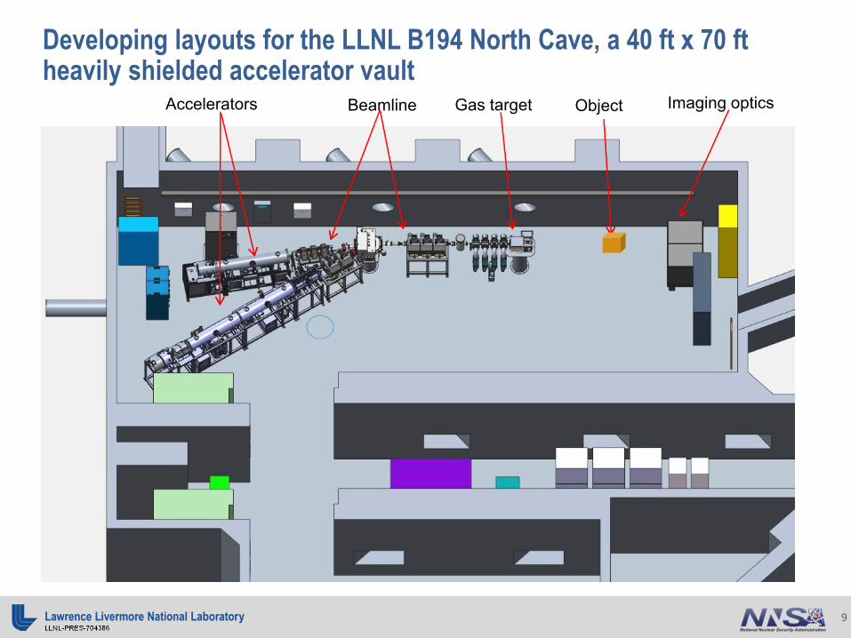
Developing layouts for the LLNL B194 North Cave, a 40 ft x 70 ftheavily shielded accelerator vault
Imaging opticsGas targetBeamline Accelerators Object

LLNL-PRES-70438610
Deuteron accelerator system for full power imaging : 7 MeV deuteron Accsys DL7
RFQs are the first two acceleration structures
A DTL is the third acceleration structure
- Accsys progress > 80% complete- Completed all design reviews this year- Entering into assembly and integration phase- Production on track- DL7 scheduled for delivery April 2017
ECR driven ion source and
magnetic low energy beam
transport

LLNL-PRES-70438611
Additional peak power testing accelerator: 4 MeV deuteron Accsys DL4
- DL4 refurbishment >95% complete- Fixed beamline diagnostic being fabricated to
allow testing DL4 to full spec at factory- DL4 to be returned October 2016
metric DL7 DL4
energy (MeV) 7.07 4.1
ave current (uA) 300 100
peak current (mA) 17 15
duty factor (%) 2.1 1.0
ave beam power (W) 2100 400
peak beam power (kW) 120 61
The DL4 machine allows for early high peak power testing of the target and components, but lacks the average power suitable for imaging testing
The DL7 machine will give the high average current needed to achieve the required integrated fluence

LLNL-PRES-70438612
Beamline physics design completed that should achieve ~1.5 mm spot size using 5 quadrupoles and 1 dipole

LLNL-PRES-70438613
Beamline optics development is well along with magnetic dipole and quads being made by Stangenes Industries
- Contract awarded to Stangenes Industries- Completed CDR and FDRs- Order included power supplies matched to
magnets- Dipole being finished, quad production started- Magnet delivery scheduled for Oct-Dec 2016
LLNL-PRES-70438614
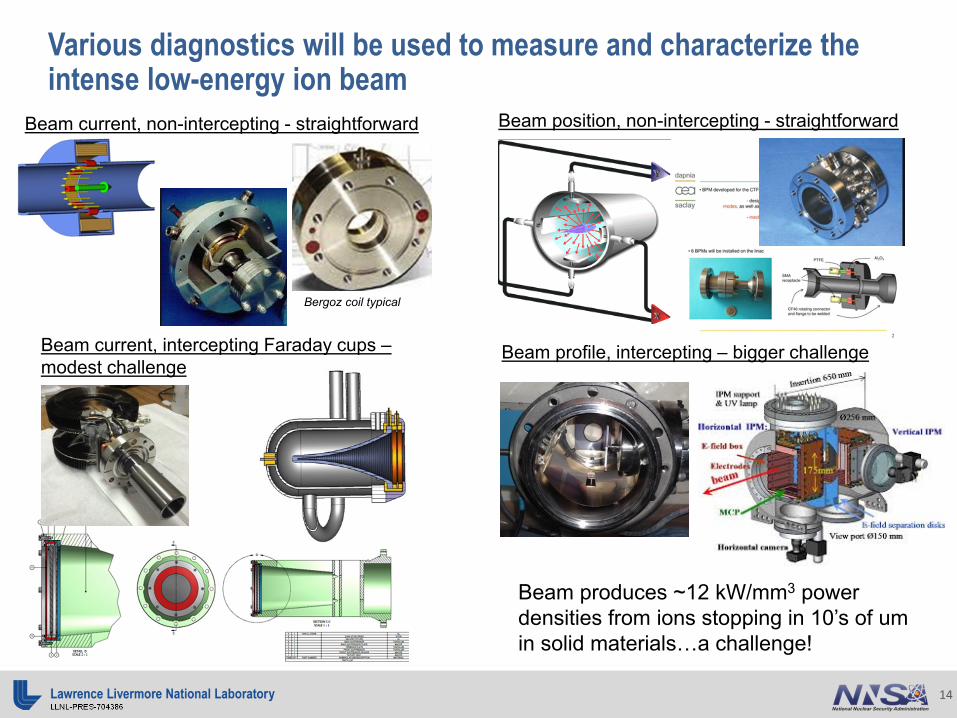
Various diagnostics will be used to measure and characterize the intense low-energy ion beam
Beam current, non-intercepting - straightforward
Beam current, intercepting Faraday cups –modest challenge
Beam position, non-intercepting - straightforward
Beam profile, intercepting – bigger challenge
Bergoz coil typical
Beam produces ~12 kW/mm3 power densities from ions stopping in 10’s of um in solid materials…a challenge!

LLNL-PRES-70438615
A transmission-type deuterium gas cell will produce the desired neutron spectrum and intensity with:• A nominal 7 MeV and 300 uA average current deuteron beam, pulsed at a 2% duty factor with
17 mA in a macrobunch• A deuterium gas cell target operating at 3 atm-gauge will produce
10 MeV neutrons at ~1011 n/s/sr at 0o
As this machine is for imaging, a small source spot size is needed (1.5 mm diam x 40 mm long = 71 mm3 = ) for sub-mm image resolution
To prevent knock-on neutrons and damage due to deuterium buildup in a solid beam stop, an argon gas beam stop is being developed
A high brightness source of fast neutrons is achieved by impinging a tightly-focused deuteron beam onto fixed-length deuterium gas column
apertures stopping gasd+ beam
deuterium gas
analyses done: D2 gas mix area Ar stop
TRIM calc of stopping
LLNL-PRES-70438616
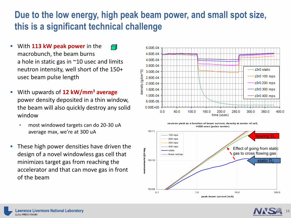
Due to the low energy, high peak beam power, and small spot size, this is a significant technical challenge
With 113 kW peak power in the macrobunch, the beam burns a hole in static gas in ~10 usec and limits neutron intensity, well short of the 150+ usec beam pulse length
With upwards of 12 kW/mm3 average power density deposited in a thin window, the beam will also quickly destroy any solid window• most windowed targets can do 20-30 uA
average max, we’re at 300 uA
These high power densities have driven the design of a novel windowless gas cell that minimizes target gas from reaching the accelerator and that can move gas in front of the beam
neutron yield as a function of beam current, density at center of cell, t=220 usec (pulse center)
1E+09
1E+10
1E+11
0.1 1.0 10.0 100.0
peak beam current (mA)
neut
rons
/sec
/st @
0 d
eg
100 mps
200 mps
300 mps
400 mps
static
linear extrap
Effect of going from static gas to cross flowing gas
static D2
flowing D2

LLNL-PRES-70438617
The rotary valve design will meter pressurized gas flow, aperture-restrict gas leakage to the beamline vacuum, and reduce leakage to the chamber with close gap tolerances
n production deuterium flow
deuteron beam
beam stop argon flow
rotary valve head
motor
valve manifold assy
bearing doubletsenclosure
rotary valve assembly:- ~12”x12”x24” in size and 300 lbs.- rotates up to ~3,600 rpm- made mostly of 7075 series aluminum to minimize activation products
intergas mixing chamber
beam stop terminus
rotor assembly

LLNL-PRES-70438618
The valve geometry generates a number of coupled vignettingmotions corresponding to beam aperture, gas inlet, and gas exhaust functions
Rotary valve gas inlet open
Aperture hole open
Beam diameter open
Beam pulse
Gas pulse
The geometry and rotational dynamics of the rotary valve system was configured to accommodate a 2% duty factor pulsed linac
D2 gasD+ ionsrotary valve opening
fixed front aperture
rotating valve rotor
rotational motion
Ar gas
LLNL-PRES-70438619
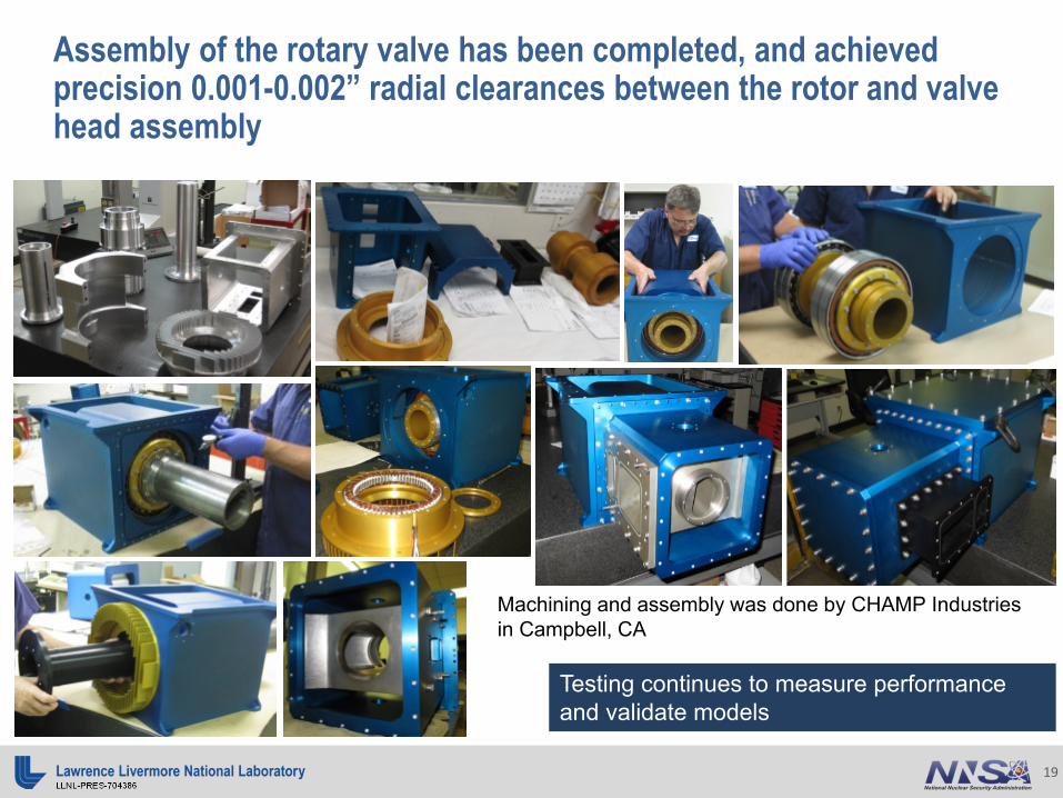
Assembly of the rotary valve has been completed, and achieved precision 0.001-0.002” radial clearances between the rotor and valve head assembly
Testing continues to measure performance and validate models
Machining and assembly was done by CHAMP Industries in Campbell, CA

LLNL-PRES-70438620
Process gas compressor installation is a significant undertaking- Completed compressor anchoring calculation
and process- Completed initial safety analysis- Completed updated P&ID diagram to guide
piping installation- Completed detailed piping layout design- Installation completion expected by October
2016

LLNL-PRES-70438621
Significant effort going into the understanding and modeling of the differential pumping line for gas capture
Characterizing gas propagation, mixing, and flow regimes across 6 orders of magnitude a complicated modeling problem
A preliminary testing apparatus was created to benchmark model
Want to avoid gas jetting regime which enhances transport

LLNL-PRES-70438622
The lens-coupled imaging optics system uses a fast (f~2) lens with short focal length (<1m) and large viewing area (60x60cm) to focus light from the scintillator onto a 4096x4096 cooled CCD camera
ShutterBellows LensCCD camera
The lens was built by Optics 1, and the camera by Spectral Instruments
Both have performed well in initial testing Test pattern image taken by system

LLNL-PRES-70438623
Predicted neutron dose map with no local shielding shows high radiation flux in cave – a major concern for electronics

LLNL-PRES-70438624
Installing localized iron and borated poly shielding around the production source lowers neutron fluxes by ~104
10 -7
10 +7
10 +5
10 +3
10 +1
10 -1
10 -3
10 -5
Neutron Flux [n/cm
2/sec]
E
N
30’
0˚ Cave( model truncated )
Transport beyondMC terminated
* Note: Results shown here are rendered at the same contrast level as the sad703 results (nominal intensity) to facilitate comparison.
SST & BPE sarcophagus surrounding RV assembly; SST & BPE ± 3.6˚ collimator; max cred. doghouse; 4” BPE beam dump

LLNL-PRES-70438625
Technology development roadmap
Early testing with the DL4 and developmental beamline are risk reduction activities
They also serve as a schedule delay hedge on DL7 fabrication
There is a lot to do!
Later stage development will optimize system for compactness
near term critical path

LLNL-PRES-70438626
Conclusions for source development for neutron imaging
Approximately 15 years of development work has allowed ample time for the overall technology approach to mature
A Fast Neutron Imaging Demonstration machine is well within reach using the current design concepts and technologies
We are well positioned to complete the remaining development work, build, and test this novel high brightness source
With the commissioning of the accelerators and beam line, we will be able to do actual beam testing of targets to better understand and advance target technology – a very important next step!
The current development path will allow for advancing the technique of fast neutron imaging as well as allow for a variety of nuclear physics measurements
