development of a manufacturing process for high-power · pdf file ·...
TRANSCRIPT
Progress Report No. F/MAE/NG/-2017-1
Development of a Manufacturing Process for High-Power-Density Hollow
Shafts
Submitted to FIERF
By
Hao Pang, Research Assistant
Gracious Ngaile, Professor
North Carolina State University
Department of Mechanical and Aerospace Engineering
Advanced Metal Forming and Tribology Laboratory (AMTL)
March, 2017
For Restricted Distribution only
(This report is distributed only to the AMTL Members. Approval must be requested from the
Lab Authority prior to distribution to other organizations or individuals)
2
FOREWORD This document has been prepared by the Advanced Metal Forming and Tribology Laboratory in
the Department of Mechanical and Aerospace Engineering at North Carolina State University.
The research focus of this Lab includes manufacturing process modeling and optimization,
triboscience and tribotechnology, tool design, and computational tools. In addition to conducting
industry relevant engineering research, the Lab has the objectives a) establish close cooperation
between industry and the university, b) train students, and c) transfer the research results to
interested companies.
This report, entitled “Development of a Manufacturing Process for High-Power-Density Hollow
Shafts”, presents a novel non-isothermal forming process for the hollow axle shaft, main shaft
and pinion gear shaft. This process is evaluated in terms of formability, forming load and
dimensional accuracy with FEM simulation.
For further information, contact Dr. Gracious Ngaile, located at North Carolina State University,
Department of Mechanical & Aerospace Engineering, 911 Oval Drive – 3160 Engineering
Building III, BOX 7910, Raleigh, NC, 27695-7910, phone: 919-515-5222,
email:[email protected], webpage:http://www.mae.ncsu.edu/ngaile.
3
Table of Content
Chapter 1 Introduction, Objective and Approach .......................................................................................... 7
1.1. Introduction .................................................................................................................................. 7
1.2. Objectives .................................................................................................................................... 12
1.3. Approach and Report Organization ............................................................................................. 13
Chapter 2 Development of Forging Process to Produce Hollow Axle Shaft .................................................. 14
2.1. Forging Process of Hollow Axle Shaft with Specified Wall Thickness ........................................... 14
2.1.1. Design of the Forging Sequence for Hollow Axle Shaft with Specified Wall Thickness ........ 14
2.1.2. FE Modeling for Hollow Axle Shaft with Specified Wall Thickness ...................................... 15
2.1.3. FE Simulation Results for Hollow Axle Shaft with Specified Wall Thickness ........................ 16
2.2. Optimization of Die Design and Process Design for Hollow Axle Shaft ........................................ 18
2.3. Forging Process of Hollow Axle Shaft with Double Flanges ......................................................... 22
2.3.1. Design of the Forging Sequence for Hollow Axle Shaft with Double Flanges ...................... 22
2.3.2. FE Modeling for Hollow Axle Shaft with Double Flanges ..................................................... 23
2.3.3. FE Simulation Results for Hollow Axle Shaft with Double Flanges ....................................... 29
Chapter 3 Development of Forging Process to Produce Hollow Main Shaft ................................................ 33
3.1. Optimization of Die Design for Thin Walled Main Shaft and Solution to the Wall Thickening Problem ................................................................................................................................................... 33
3.2. Forging Process of Hollow Main Shaft with Double Flanges ........................................................ 38
3.2.1. Design of the Forging Sequence for Hollow Main Shaft with Double Flanges ..................... 38
3.2.2. FE Modeling for Hollow Main Shaft with Double Flanges .................................................... 39
3.2.3. FE Simulation Results for Hollow Main Shaft with Double Flanges ..................................... 46
Chapter 4 Development of Forging Process to Produce Hollow Pinion Gear Shaft ..................................... 49
4.1. Sequence 1: Extrusion Stage before the Non-isothermal Forging Process ................................. 49
4.1.1. FE Modeling of Sequence 1 ................................................................................................. 50
4.1.2. FE Simulation Results of Sequence 1 ................................................................................... 53
4.2. Sequence2 : Extrusion Stage in the middle of the Non-isothermal Forging Process ................... 54
Chapter 5 Application of the Non-isothermal Forging Process to the Aluminum Workpiece ....................... 57
5.1. Comparison of the Non-isothermal Forging Process for Al and Steel.......................................... 57
5.2. Feasibility of the Non-isothermal Forging Process for the Al Workpiece .................................... 60
Chapter 6 Induction Heating Design ............................................................................................................ 62
6.1. Definition, application and advantage of Induction Heating ....................................................... 62
6.2. Design of the Induction Heating by Analytical Calculation .......................................................... 63

4
6.3. FE Modeling ................................................................................................................................. 69
6.3.1. FE Modeling of the Eddy Current Analysis ........................................................................... 69
6.3.2. FE Modeling of the Transient Thermal Analysis .................................................................. 73
6.4. FE Simulation Results for Induction Heating ............................................................................... 75
Chapter 7 Concluding Remarks ................................................................................................................... 77
Reference .................................................................................................................................................... 79
5
List of Figures
Figure 1-1. Axle Shaft, Main Shaft and Pinion Gear Shaft .......................................................................... 8
Figure 1-2. Forging Sequence of the Non-isothermal Forging Process for the Axle Shaft .......................... 9
Figure 1-3. Strain Distribution of the Axle Shaft by the Non-isothermal Forging ..................................... 10
Figure 1-4. Forging Sequence of the Non-isothermal Forging Process for the Main Shaft ....................... 10
Figure 1-5 Strain Distribution of the Main Shaft by the Non-isothermal Forging ..................................... 11
Figure 1-6. Forging Sequence of the Non-isothermal Forging Process for the Pinion Gear Shaft ............. 11
Figure 1-7. Strain Distribution of the Pinion Gear Shaft by the Non-isothermal Forging .......................... 12
Figure 2-1. Ironing Operation ..................................................................................................................... 15
Figure 2-2. Beginning and End of the Ironing Operation ........................................................................... 16
Figure 2-3. Wall Thickness Distribution with and without the Ironing Operation ..................................... 17
Figure 2-4. Stress Distribution of Tubular Body ........................................................................................ 17
Figure 2-5. Manufacturing Process for the Axle Shaft with a Specified Wall Thickness .......................... 18
Figure 2-6. Optimized Die Design of the Upsetting Operation .................................................................. 18
Figure 2-7. FEM Modeling of the Configuration of the Workpiece and the Dies ...................................... 19
Figure 2-8. Forming Load, the Effective Stress and Tolerance of the Outer Radius at the Step 700 ......... 20
Figure 2-9. Forming Load, the Effective Stress and Tolerance of the Outer Radius at the Step 736 ......... 21
Figure 2-10. Extrusion Operation After the Upsetting Operation............................................................... 21
Figure 2-11. Improvement on the Radial Tolerance by the Extrusion Operation ....................................... 22
Figure 2-12. Sequence of Forging Process for the Axle Shaft with Double Flanges ................................. 23
Figure 2-13 Thermal Boundary Conditions ................................................................................................ 25
Figure 2-14. Beginning and End of the Upsetting Operation ..................................................................... 26
Figure 2-15. Beginning and End of the Heading Operation ....................................................................... 26
Figure 2-16. Beginning and End of the Blocking Operation ...................................................................... 28
Figure 2-17. Beginning and End of the Finishing Operation ...................................................................... 29
Figure 2-18. Strain Distribution of the Final Part ....................................................................................... 31
Figure 2-19. Load-Stroke Curve ................................................................................................................. 31
Figure 2-20. Alternative Forging Process for the Double-flanged Axle Shafts .......................................... 32
Figure 2-21. Cross rolling and Flow Forming ............................................................................................ 32
Figure 3-1. Two Phases of Upsetting of a Workpiece (ID=30 mm) ........................................................... 34
Figure 3-2. Temperature Distribution at the Transitional Region............................................................... 34
Figure 3-3. Wall Thickening Problem ........................................................................................................ 34
Figure 3-4. Introduction of Mandrel ........................................................................................................... 35
Figure 3-5. Modified Top Die ..................................................................................................................... 35
Figure 3-6. FEM Model after the Die Geometries Change ......................................................................... 36
Figure 3-7. Final Part after Introduction of the Mandrel ............................................................................ 37
Figure 3-8. Load-Stroke of the Upsetting Operation .................................................................................. 37
Figure 3-9. Load-Stroke of the Flanging Operation ................................................................................... 37
Figure 3-10. Forging Sequence for the Main Shaft with Double Flanges .................................................. 39
Figure 3-11 Thermal Boundary Condition ................................................................................................. 40
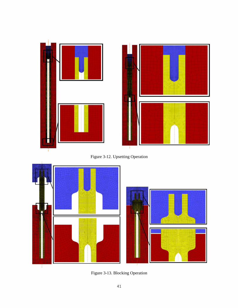
Figure 3-12. Upsetting Operation ............................................................................................................... 41
6
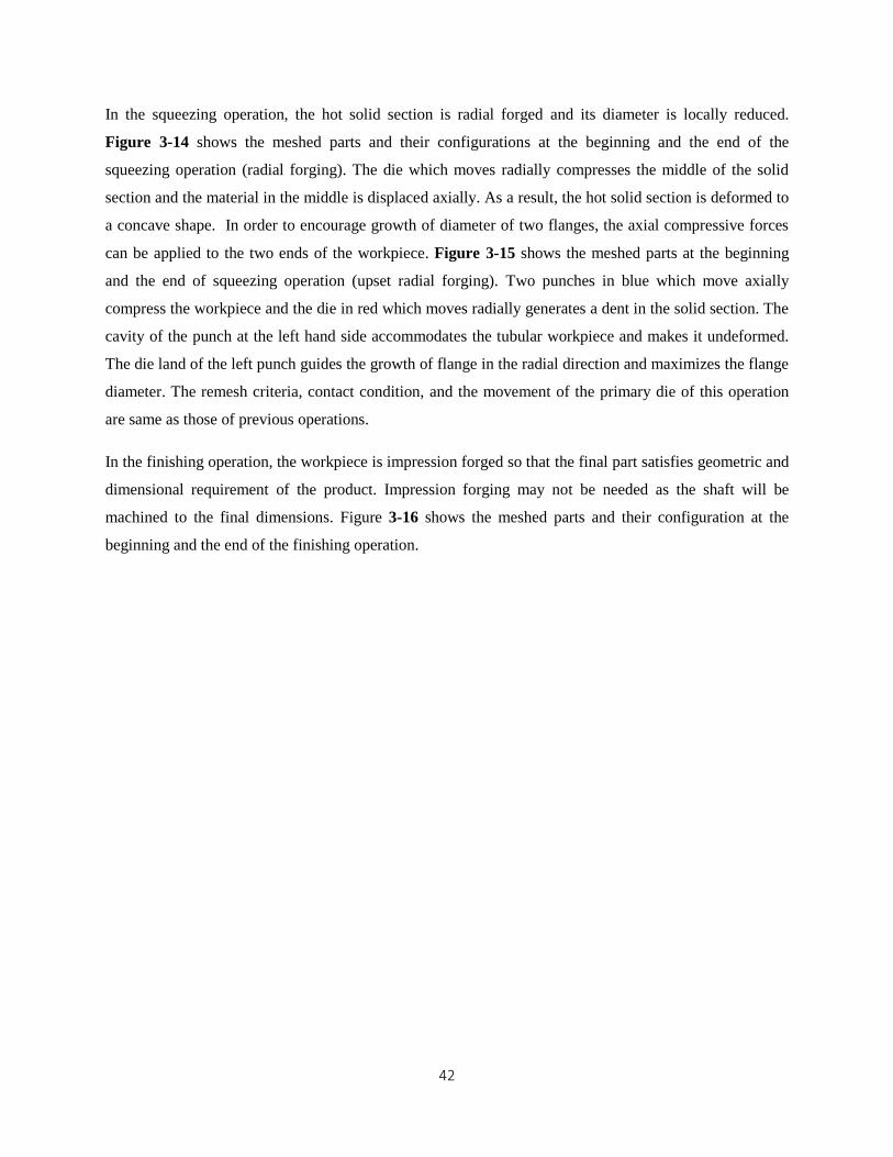
Figure 3-13. Blocking Operation ................................................................................................................ 41
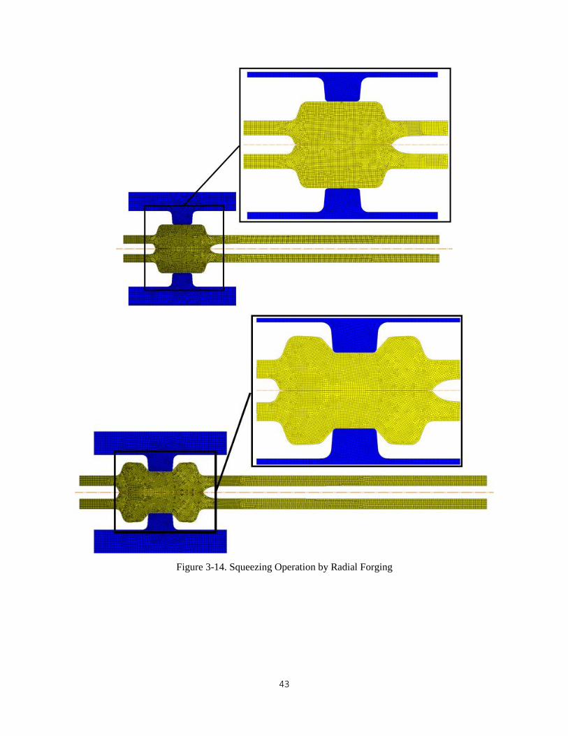
Figure 3-14. Squeezing Operation by Radial Forging ................................................................................ 43
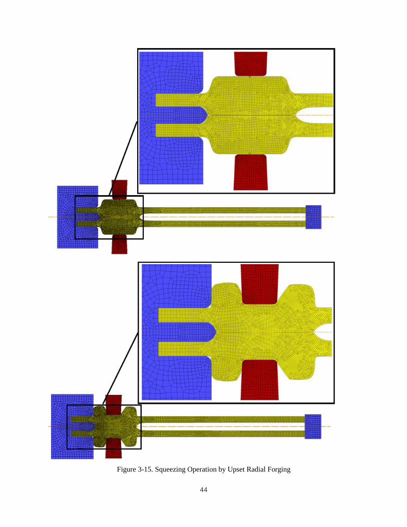
Figure 3-15. Squeezing Operation by Upset Radial Forging ...................................................................... 44
Figure 3-16. Finishing Operation ................................................................................................................ 45
Figure 3-17. Flange Diameter of the Workpiece by Radial Forging (left) and Upset Radial Forging (right)
.................................................................................................................................................................... 47
Figure 3-18. Strain Distribution of the Main Shaft with Double Flanges ................................................... 47
Figure 3-19. Load-Stroke of the Forging Process for the Main Shaft with Double Flanges ...................... 48
Figure 4-1. the First Forging Sequence for the Pinion Gear Shaft ............................................................. 50
Figure 4-2. FEM Modeling of the Extrusion Operation ............................................................................. 51
Figure 4-3. FEM Modeling of the Upsetting Operation ............................................................................. 52
Figure 4-4. FEM Modeling of the Coning Operation ................................................................................. 53
Figure 4-5. Strain Distribution of the Final Part by the New Forging Sequendce ...................................... 53
Figure 4-6. the Second Forging Sequence for the Pinion Gear Shaft ......................................................... 54
Figure 4-7. FEM Modeling of the Extrusion Operation ............................................................................. 55
Figure 5-1. Flow Stress of AISI 4140 ......................................................................................................... 58
Figure 5-2. Temperature Distribution of AISI 4140 ................................................................................... 58
Figure 5-3. Yield Stress of the AISI 4140 versus the Temperature ............................................................ 59
Figure 5-4. Effective Stress Distribution of AISI 4140 .............................................................................. 59
Figure 5-5. Flow Stress of Aluminum 3003 ............................................................................................... 59
Figure 5-6. Temperature Distribution of Aluminum 3003 ......................................................................... 59
Figure 5-7. Yield Stress of the Aluminum 3003 versus the Temperature .................................................. 60
Figure 5-8. Effective Stress Distribution of Aluminum 3003 ..................................................................... 60
Figure 5-9. Strain Distribution of the Final Part (Aluminum 3003) ........................................................... 61
Figure 5-10. Load-Stroke of the Upsetting Operation (Aluminum 3003) .................................................. 61
Figure 5-11. Load-Stroke of the Flanging Operation ................................................................................. 61
Figure 6-1. Application of the Induction Heating [3] ................................................................................. 63
Figure 6-2. Electric Efficiency versus Critical Efficiency [3] .................................................................... 64
Figure 6-3.Calculation Procedure of Input Coil Current and Coil Power ................................................... 65
Figure 6-4. Dimensions and Configuration of the Workpiece and the Coil ............................................... 66
Figure 6-5. Workpiece Resistance Factor 𝐊𝐑𝟐 [3] .................................................................................... 68
Figure 6-6. FEM Modeling of Induction Heating ....................................................................................... 70
Figure 6-7. Section Shape of Magnetic Flux as a Function of Magnetic Field Strength and Temperature 71
Figure 6-8. Surface of Magnetic Flux as a Function of Magnetic Field Strength and Temperature .......... 71
Figure 6-9. Thermal Modifier of the Magnetic Flux .................................................................................. 72
Figure 6-10. Thermal Modifier of the Conductivity ................................................................................... 72
Figure 6-11. Meshed Parts in the Transient Thermal Analysis ................................................................... 74
Figure 6-12. Thermal Conductivity of AISI 4140 ...................................................................................... 75
Figure 6-13. Specific Heating of AISI 4140 ............................................................................................... 75
Figure 6-14. Ohmic Loss in the Workpiece ................................................................................................ 76
Figure 6-15. Temperature Distribution of the Workpiece after Induction Heating .................................... 76

7
Chapter 1
Introduction, Objective and Approach
1.1. Introduction
Lightweighting is being actively researched worldwide. The motivation to reduce the weight of a vehicle
is largely driven by government regulations. For example, the fuel mileage requirement for cars in the US
will increase to 35 mpg in 2020 [1]. For heavy duty trucks, the US is expected to cut carbon pollution by
17% from 2005 levels by 2020 [2]. The power train for cars and trucks carries a significant percentage of
the total weight of a vehicle. For example, the power train in Classes 1-3 accounts for 36% of the total
weight, whereas in Class 8 the power train accounts for 48%.The majority of power transmission systems
used in the automotive, aerospace, maritime, and other industries employ solid shafts. Utilization of
hollow shafts can drastically reduce weight, thus improving fuel efficiency. Although there are different
ways that hollow shafts could be produced (e.g., machining), to meet the demand in the above-mentioned
industries, any new manufacturing process must meet the following criteria: mass production potential,
short cycle time, structural integrity, and cost effectiveness. The goal of this study is to devise a
fabrication process that will combine (a) an innovative forming concept based on differential heating, (b)
geometric optimization, and (c) multi-functional heat treatment.
Differential heating-based forming which will also be referred to in this report as the non-isothermal
forging presents the opportunity of creating a pseudo die, the part of the billet material that would act as a
die or punch to transmit the forming load to the desired regions. This methodology offers new
possibilities for designing high-power-density shafts. Although managing differential heating poses a
challenge, most forging companies use similar technologies for billet heating or heat treatment on specific
locations of forged parts.
Geometric optimization for a hollow shaft refers to taking out material in the shaft that does not carry
substantial load. For example, for a shaft with a bore diameter that is half the outer diameter, the second
moment of area will be 10% lower than for the solid shaft. This hollow shaft reduces weight by 30%
while negligibly reducing rigidity and strength.
Multi-functional heat treatment scheme. Heat treatment is commonly used to impart the desired hardness
and strength on a product. The majority of failures in engineering materials, such as fatigue fracture,
fretting, wear, and corrosion, are sensitive to the structure and properties of the material surface and
usually originate from the exterior layer of the product. Fatigue strength of the product can be enhanced
by producing compressive residual stress, which increases surface hardness and grain refinement. To
increase fatigue life, many components in the aerospace and automotive sectors (crank shafts, gears,

8
turbine blades, etc.) undergo shot peening to induce compressive residual stresses [3-9]. In shot peening,
hardened balls are bombarded at the surface at high velocity, thus inducing compressive residual stresses
on the surface. A heat treatment scheme that could impart desired hardness on the surface and also induce
compressing stress on the product might significantly increase the load-carrying capacity of the part.
Because shot peening is a deformation operation, there is a threshold hardness beyond which shot peening
cannot be used effectively. Intensive quenching (IQ) heat treatment can be categorized as a multi-
functional heat treatment scheme because it imparts part strength and hardness and creates a compressive
layer at the maximum hardness achievable. In this development effort, we will use the IQ heat treating
technology due to its unique characteristics.
In our early report on Light Weight Forging project for heavy duty trucks that was funded by FIERF and
AISI, we introduced the concept of “differential heating based forging” using hollow tube as a billet. This
forging scheme can be applied for production of typical power transmission shafts, i.e. axle shafts,
gearbox main shafts and pinion gear shafts,
Figure 1-1. Preliminary FE analysis of the forging schemes for hollow axle shafts, gear box main shafts,
and hollow pinion gear shafts were presented in [10]. We will briefly summarize the result here.
Axle Shaft Main Shaft Pinion Gear Shaft
Figure 1-1. Axle Shaft, Main Shaft and Pinion Gear Shaft
9
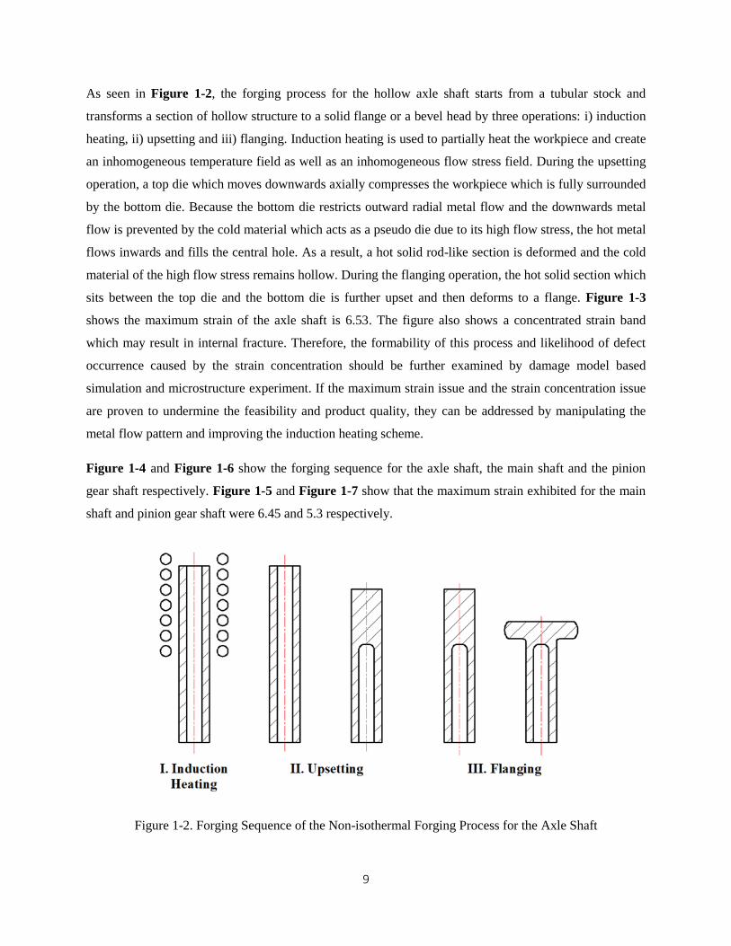
As seen in Figure 1-2, the forging process for the hollow axle shaft starts from a tubular stock and
transforms a section of hollow structure to a solid flange or a bevel head by three operations: i) induction
heating, ii) upsetting and iii) flanging. Induction heating is used to partially heat the workpiece and create
an inhomogeneous temperature field as well as an inhomogeneous flow stress field. During the upsetting
operation, a top die which moves downwards axially compresses the workpiece which is fully surrounded
by the bottom die. Because the bottom die restricts outward radial metal flow and the downwards metal
flow is prevented by the cold material which acts as a pseudo die due to its high flow stress, the hot metal
flows inwards and fills the central hole. As a result, a hot solid rod-like section is deformed and the cold
material of the high flow stress remains hollow. During the flanging operation, the hot solid section which
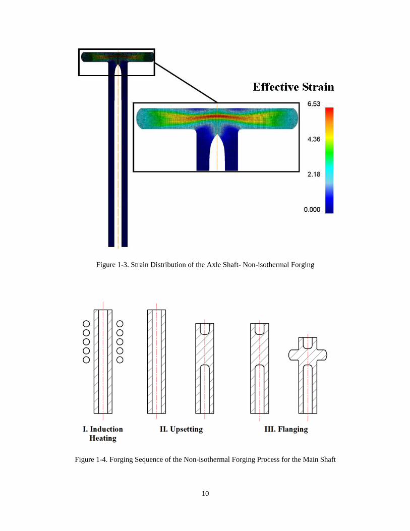
sits between the top die and the bottom die is further upset and then deforms to a flange. Figure 1-3
shows the maximum strain of the axle shaft is 6.53. The figure also shows a concentrated strain band
which may result in internal fracture. Therefore, the formability of this process and likelihood of defect
occurrence caused by the strain concentration should be further examined by damage model based
simulation and microstructure experiment. If the maximum strain issue and the strain concentration issue
are proven to undermine the feasibility and product quality, they can be addressed by manipulating the
metal flow pattern and improving the induction heating scheme.
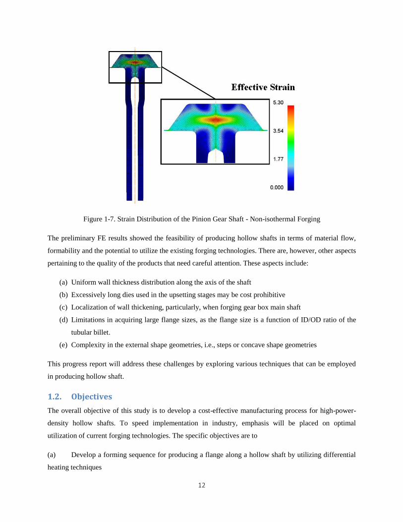
Figure 1-4 and Figure 1-6 show the forging sequence for the axle shaft, the main shaft and the pinion
gear shaft respectively. Figure 1-5 and Figure 1-7 show that the maximum strain exhibited for the main
shaft and pinion gear shaft were 6.45 and 5.3 respectively.
Figure 1-2. Forging Sequence of the Non-isothermal Forging Process for the Axle Shaft
10
Figure 1-3. Strain Distribution of the Axle Shaft- Non-isothermal Forging
Figure 1-4. Forging Sequence of the Non-isothermal Forging Process for the Main Shaft

11
Figure 1-5 Strain Distribution of the Main Shaft - Non-isothermal Forging
Figure 1-6. Forging Sequence of the Non-isothermal Forging Process for Pinion Gear Shaft
12
Figure 1-7. Strain Distribution of the Pinion Gear Shaft - Non-isothermal Forging
The preliminary FE results showed the feasibility of producing hollow shafts in terms of material flow,
formability and the potential to utilize the existing forging technologies. There are, however, other aspects
pertaining to the quality of the products that need careful attention. These aspects include:
(a) Uniform wall thickness distribution along the axis of the shaft
(b) Excessively long dies used in the upsetting stages may be cost prohibitive
(c) Localization of wall thickening, particularly, when forging gear box main shaft
(d) Limitations in acquiring large flange sizes, as the flange size is a function of ID/OD ratio of the
tubular billet.
(e) Complexity in the external shape geometries, i.e., steps or concave shape geometries
This progress report will address these challenges by exploring various techniques that can be employed
in producing hollow shaft.
1.2. Objectives
The overall objective of this study is to develop a cost-effective manufacturing process for high-power-
density hollow shafts. To speed implementation in industry, emphasis will be placed on optimal
utilization of current forging technologies. The specific objectives are to
(a) Develop a forming sequence for producing a flange along a hollow shaft by utilizing differential
heating techniques

13
(b) Explore multi-functional heat treatment techniques where hardness is increased and compressive
stresses are induced
(c) Carry out economic analysis with focus on the architecture of forming sequences and hollow
billet production
(d) In collaboration with a forging company, a steel manufacturing company, and a heat treatment
company, build a demonstration test setup. Potential parts include axle shaft and output.
1.3. Approach and Report Organization
Finite element analysis (FEM) is used to develop and evaluate the forging process. Induction heating is
developed with the aid of analytical calculations and FEM simulation. The finite element analysis
software Deform2D is used to carry out metal forming simulations and ANSYS is used for the induction
heating simulation. Although there are four main objectives as stated above, this progress report will
address the first objective.
In Chapter 2, an ironing stage is added to the non-isothermal forging scheme to increase wall thickness
uniformity. The bottom die of the upsetting operation is partitioned into two to avoid fabricating long dies.
A hybrid forging process which incorporates the non-isothermal forging is developed to produce the axle
shaft with double flange. Its feasibility is evaluated based on formability and the forming load.
In Chapter 3, dies are redesigned to facilitate forging of the main shaft with a sizable flange from a thin
walled tubular stock and the wall thickening problem during the upsetting operation is addressed. A
hybrid forging process which combines the non-isothermal forging process with other forging
technologies is developed to produce gear box main shaft with double flanges. Its feasibility is evaluated
based on formability and forming load.
In Chapter 4, two forging sequences each of which combines the non-isothermal forging with a type of
hollow extrusion are developed to improve the geometric and dimensional accuracy of the workpiece.
Their feasibility is evaluated based on the formability. Advantages and disadvantages of each forging
sequence are presented and compared.
In Chapter 5, non-isothermal forging process for aluminum workpiece is examined. Effects of change in
the workpiece material on the deformation characteristic and product geometries are investigated.
Chapter 6 discuses analytical and numerical calculations to estimate process parameters for induction
heating.
14
Chapter 2
Development of Forging Process to Produce Hollow Axle Shaft
This chapter addressees: i) modification of the non-isothermal forging process to improve wall thickness
tolerance, ii) redesign of the bottom die of the upsetting operation by segmenting the die into two and
evaluate the effectiveness of the new design, iii) development of a new forging process which combines
the non-isothermal forging with radial forging for the double-flanged axle shaft. The feasibility of the
process is evaluated in terms of the formability and the forming load.
2.1. Forging Process of Hollow Axle Shaft with Specified Wall Thickness
2.1.1. Design of the Forging Sequence for Hollow Axle Shaft with Specified Wall
Thickness Based on customer specifications, the wall thickness of a tubular body of the shaft may be required to be
uniform in the axial direction. Although non-isothermal forging process is able to achieve wall thickness
tolerance of 0.316 mm for 92.25% length of the workpiece, the process can be further improved to tighten
the wall thickness tolerance. An ironing operation can be added between the upsetting operation and the
flanging operation to make the wall thickness more uniform. After the workpiece is transferred from the
upsetting station to the ironing station, it is turned upside down and placed inside the bottom die. A dome
headed plunger, which is fixed to a long rod, moves downwards and unifies the wall thickness. Because
the wall thickness always increases by a small amount due to upsetting and the diameter of the plunger is
identical to the inner diameter of the initial stock, material of the wall is radially compressed and pushed
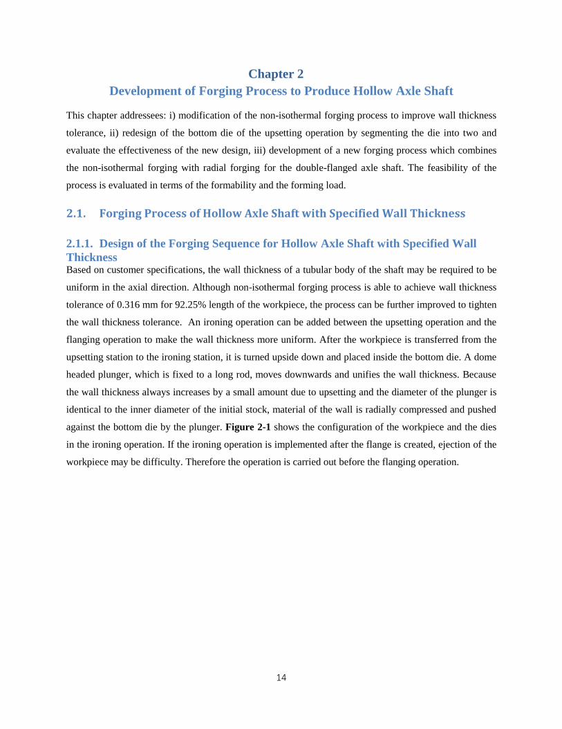
against the bottom die by the plunger. Figure 2-1 shows the configuration of the workpiece and the dies
in the ironing operation. If the ironing operation is implemented after the flange is created, ejection of the
workpiece may be difficulty. Therefore the operation is carried out before the flanging operation.
15
Figure 2-1. Ironing Operation
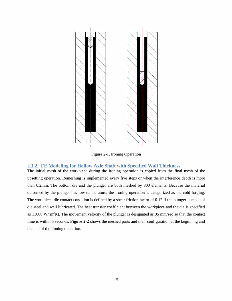
2.1.2. FE Modeling for Hollow Axle Shaft with Specified Wall Thickness The initial mesh of the workpiece during the ironing operation is copied from the final mesh of the
upsetting operation. Remeshing is implemented every five steps or when the interference depth is more
than 0.2mm. The bottom die and the plunger are both meshed by 800 elements. Because the material
deformed by the plunger has low temperature, the ironing operation is categorized as the cold forging.
The workpiece-die contact condition is defined by a shear friction factor of 0.12 if the plunger is made of
die steel and well lubricated. The heat transfer coefficient between the workpiece and the die is specified
as 11000 W/(m2K). The movement velocity of the plunger is designated as 95 mm/sec so that the contact
time is within 5 seconds. Figure 2-2 shows the meshed parts and their configuration at the beginning and
the end of the ironing operation.
16
Figure 2-2. Beginning and End of the Ironing Operation
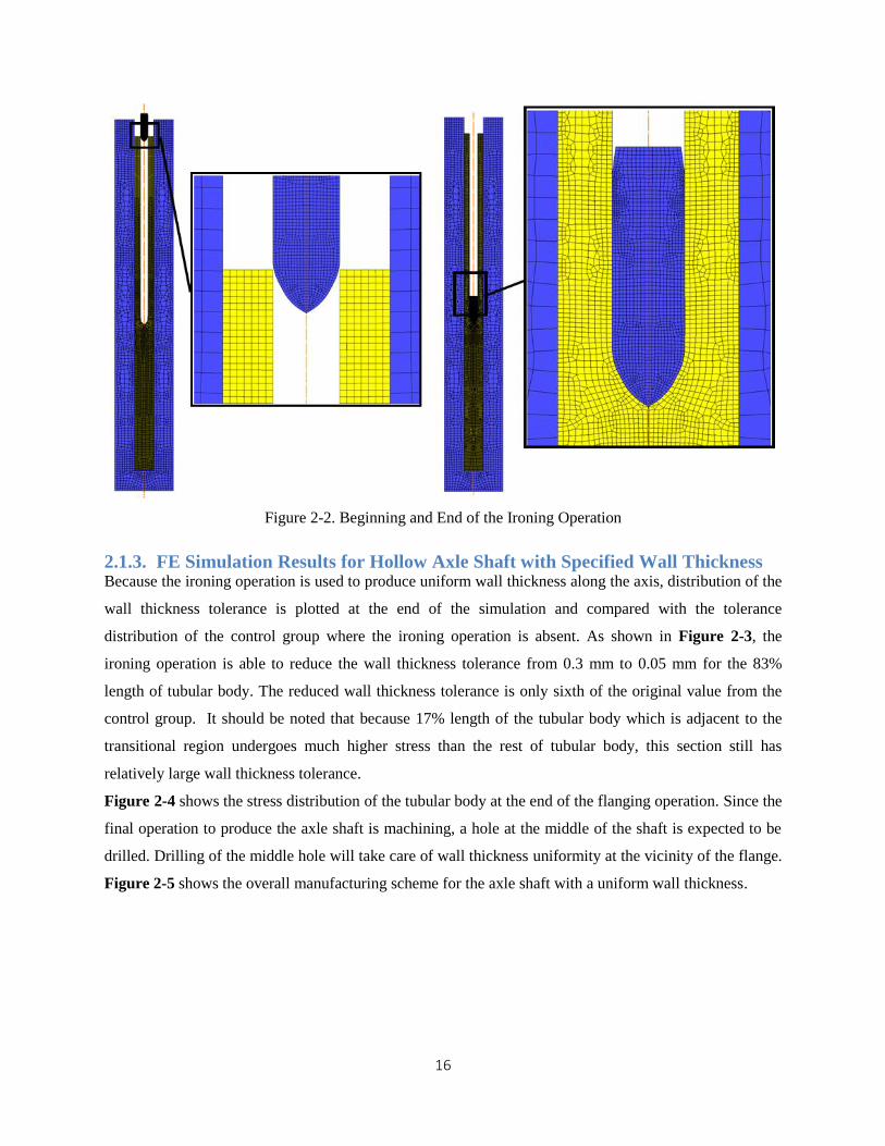
2.1.3. FE Simulation Results for Hollow Axle Shaft with Specified Wall Thickness Because the ironing operation is used to produce uniform wall thickness along the axis, distribution of the
wall thickness tolerance is plotted at the end of the simulation and compared with the tolerance
distribution of the control group where the ironing operation is absent. As shown in Figure 2-3, the
ironing operation is able to reduce the wall thickness tolerance from 0.3 mm to 0.05 mm for the 83%
length of tubular body. The reduced wall thickness tolerance is only sixth of the original value from the
control group. It should be noted that because 17% length of the tubular body which is adjacent to the
transitional region undergoes much higher stress than the rest of tubular body, this section still has
relatively large wall thickness tolerance.
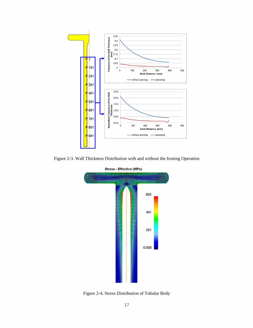
Figure 2-4 shows the stress distribution of the tubular body at the end of the flanging operation. Since the
final operation to produce the axle shaft is machining, a hole at the middle of the shaft is expected to be
drilled. Drilling of the middle hole will take care of wall thickness uniformity at the vicinity of the flange.
Figure 2-5 shows the overall manufacturing scheme for the axle shaft with a uniform wall thickness.
17
Figure 2-3. Wall Thickness Distribution with and without the Ironing Operation
Figure 2-4. Stress Distribution of Tubular Body
18
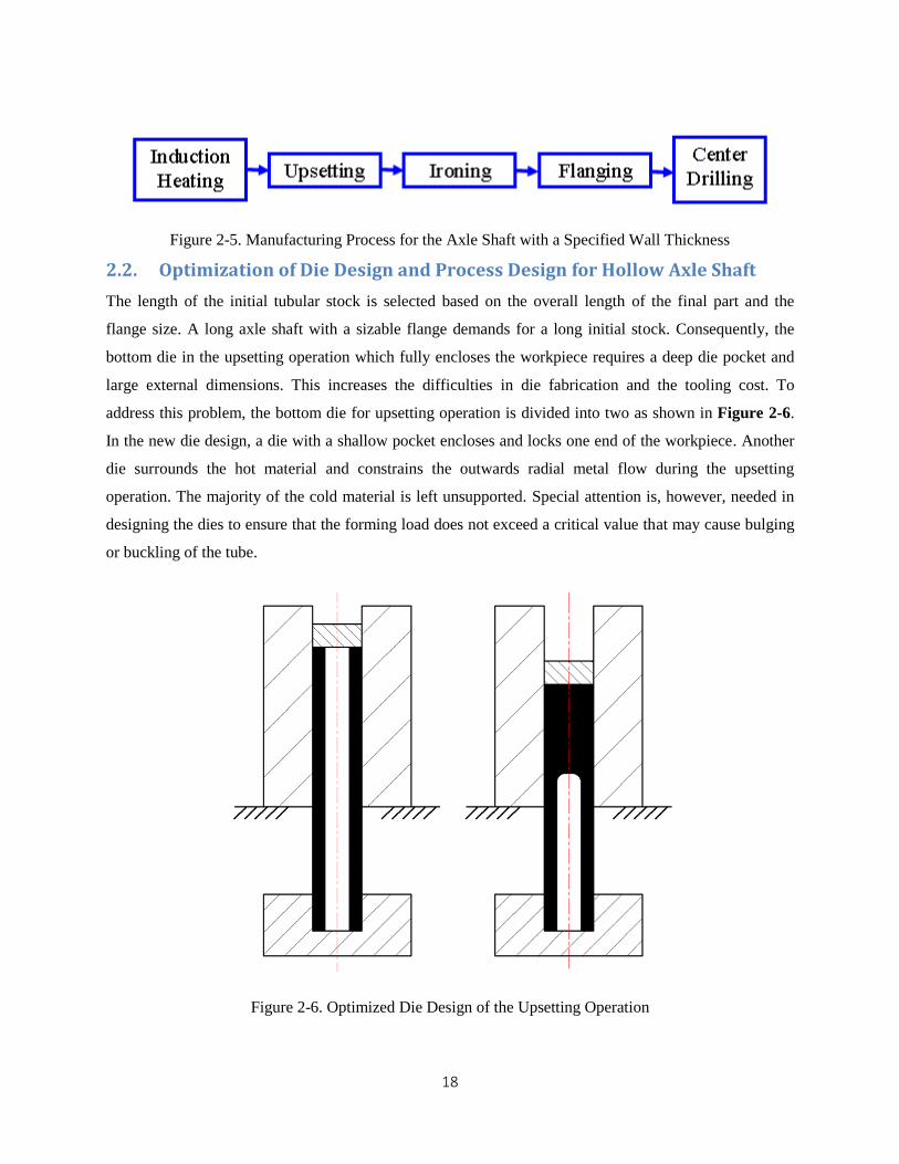
Figure 2-5. Manufacturing Process for the Axle Shaft with a Specified Wall Thickness
2.2. Optimization of Die Design and Process Design for Hollow Axle Shaft
The length of the initial tubular stock is selected based on the overall length of the final part and the
flange size. A long axle shaft with a sizable flange demands for a long initial stock. Consequently, the
bottom die in the upsetting operation which fully encloses the workpiece requires a deep die pocket and
large external dimensions. This increases the difficulties in die fabrication and the tooling cost. To
address this problem, the bottom die for upsetting operation is divided into two as shown in Figure 2-6.
In the new die design, a die with a shallow pocket encloses and locks one end of the workpiece. Another
die surrounds the hot material and constrains the outwards radial metal flow during the upsetting
operation. The majority of the cold material is left unsupported. Special attention is, however, needed in
designing the dies to ensure that the forming load does not exceed a critical value that may cause bulging
or buckling of the tube.
Figure 2-6. Optimized Die Design of the Upsetting Operation

19
In order to examine the validity of this technique, FEM simulations were carried out, Fig 2-7. The
workpiece is initially meshed by 6000 elements. Remeshing is implemented every five step or when the
interference depth is above 0.2 mm. The top die, the middle die and the bottom die are meshed by 80, 800
and 500 elements. The shear friction factor between the workpiece and the top die is defined as 0.3
because the material contacting the top die is hot and lubrication condition is assumed to good. The
interface between the middle die and the workpiece is characterized by the same shear friction factor, 0.3.
The shear fiction factor between the bottom die and the workpiece is set as 0.12 which is widely accepted
in a well lubricated cold forgoing. The heat transfer coefficient is assumed to be fixed at 11000 W/(m2K)
due to the considerable contact pressure between the workpiece and the die. The top die moves
downwards and compresses the workpiece at a constant velocity of 15 mm/sec. The FEM model of the
upsetting operation with the new die design is shown in the Figure 2-7.
Figure 2-7. FEM Modeling of the Configuration of the Workpiece and the Dies
20
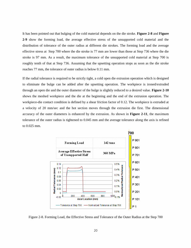
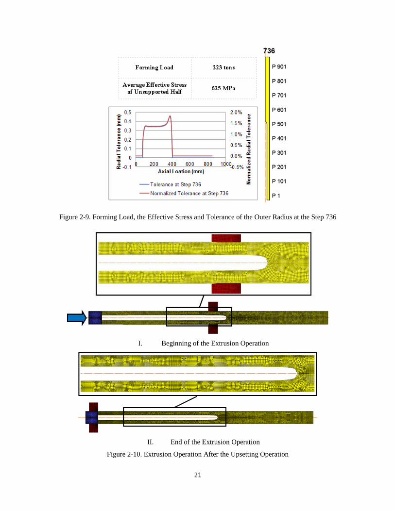
It has been pointed out that bulging of the cold material depends on the die stroke. Figure 2-8 and Figure
2-9 show the forming load, the average effective stress of the unsupported cold material and the
distribution of tolerance of the outer radius at different die strokes. The forming load and the average
effective stress at Step 700 where the die stroke is 77 mm are lower than those at Step 736 where the die
stroke is 97 mm. As a result, the maximum tolerance of the unsupported cold material at Step 700 is
roughly tenth of that at Step 736. Assuming that the upsetting operation stops as soon as the die stroke
reaches 77 mm, the tolerance of outer radius is below 0.11 mm.
If the radial tolerance is required to be strictly tight, a cold open die extrusion operation which is designed
to eliminate the bulge can be added after the upsetting operation. The workpiece is ironed/extruded
through an open die and the outer diameter of the bulge is slightly reduced to a desired value. Figure 2-10
shows the meshed workpiece and the die at the beginning and the end of the extrusion operation. The
workpiece-die contact condition is defined by a shear friction factor of 0.12. The workpiece is extruded at
a velocity of 20 mm/sec and the hot section moves through the extrusion die first. The dimensional
accuracy of the outer diameters is enhanced by the extrusion. As shown in Figure 2-11, the maximum
tolerance of the outer radius is tightened to 0.045 mm and the average tolerance along the axis is refined
to 0.025 mm.
Figure 2-8. Forming Load, the Effective Stress and Tolerance of the Outer Radius at the Step 700
21
Figure 2-9. Forming Load, the Effective Stress and Tolerance of the Outer Radius at the Step 736
I. Beginning of the Extrusion Operation
II. End of the Extrusion Operation
Figure 2-10. Extrusion Operation After the Upsetting Operation

22
Figure 2-11. Improvement on the Radial Tolerance by the Extrusion Operation
2.3. Forging Process of Hollow Axle Shaft with Double Flanges
The goal of the section is to design a forging process for the axle shaft with more complicated external
shapes. By utilizing the spatially-varying flow stress caused by the inhomogeneous temperature
distribution to transform a section of tubular structure to a solid rod, a new forging process which
combines the non-isothermal forging process and radial forging is presented. Its feasibility is verified
based on the formability and forming loads. A typical axle has one flange, this section, however, explores
the potential of forging multiple flanged axle shaft.
2.3.1. Design of the Forging Sequence for Hollow Axle Shaft with Double Flanges The whole process is composed of five operations: i) induction heating, ii) upsetting, iii) heading, iv)
blocking, and v) finishing. In the induction heating operation, the workpiece is placed at the center of the
coil and its axial position with respect to the coil is based on the heating zone needed in the product
design. In the upsetting operation, the workpiece is positioned vertically in the cavity of the bottom die
and is fully surrounded by it. A punch axially compresses the workpiece until a hot solid rod is gained at
the end of the workpiece. Because the bottom die constrains the outward radial flow of the hot material
and the cold material, which acts as pseudo-die, prevents hot material from flowing downwards, the hot
material fills the central hollow. Details on deformation mechanism and metal flow pattern can be found
in [10]. After the upsetting operation, the workpiece is transferred to a work station where the bottom die
and the top die have cylindrical cavities and is positioned at the center of the bottom die. The workpiece is
upset furthermore until the hot material fills the cavity enclosed by the dies. As a result, the hot solid rod
is shortened and its diameter increases. This operation is referred to as the heading in this case. After the
heading operation, the workpiece is radially forged by a set of dies, each of which spans 180oC angle.
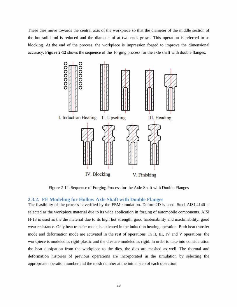
23
These dies move towards the central axis of the workpiece so that the diameter of the middle section of
the hot solid rod is reduced and the diameter of at two ends grows. This operation is referred to as
blocking. At the end of the process, the workpiece is impression forged to improve the dimensional
accuracy. Figure 2-12 shows the sequence of the forging process for the axle shaft with double flanges.
Figure 2-12. Sequence of Forging Process for the Axle Shaft with Double Flanges
2.3.2. FE Modeling for Hollow Axle Shaft with Double Flanges The feasibility of the process is verified by the FEM simulation. Deform2D is used. Steel AISI 4140 is
selected as the workpiece material due to its wide application in forging of automobile components. AISI
H-13 is used as the die material due to its high hot strength, good hardenability and machinability, good
wear resistance. Only heat transfer mode is activated in the induction heating operation. Both heat transfer
mode and deformation mode are activated in the rest of operations. In II, III, IV and V operations, the
workpiece is modeled as rigid-plastic and the dies are modeled as rigid. In order to take into consideration
the heat dissipation from the workpiece to the dies, the dies are meshed as well. The thermal and
deformation histories of previous operations are incorporated in the simulation by selecting the
appropriate operation number and the mesh number at the initial step of each operation.

24
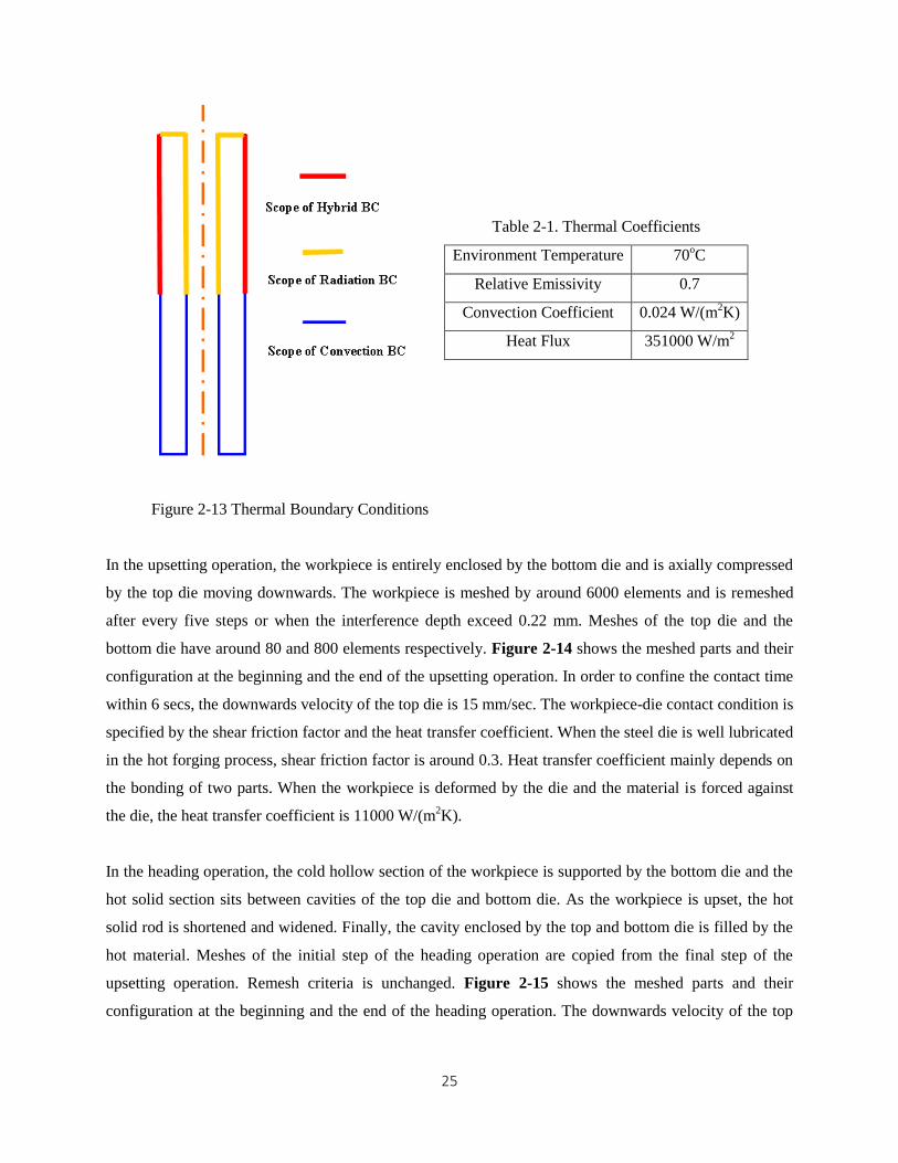
In the induction heating simulation, three types of thermal boundary conditions (BC) are applied: the
hybrid boundary condition, the radiation boundary condition and the convective boundary condition. The
scope of the three thermal boundary conditions is shown in Figure 2-13. The hybrid thermal condition
which consists of the heat flux, radiation and convection is attached to the external surface of the section
for heating. Due to the skin effect, heat generation in the workpiece due to eddy currents is equivalent to
the heat flux flowing from the exterior to interior. As the temperature rises, weights of the radiation
boundary condition and the convection radiation boundary in the heat loss vary with time. Therefore, both
convection and radiation are incorporated in the hybrid thermal boundary condition. Because the
temperature of unheated material remains relatively low and the convection dominates over the radiation
for the cold body, only convection boundary condition is attached to the section of unheated material. In
contrast, radiation accounts for majority of heat dissipation from the workpiece to the environment. As a
result, only radiation boundary condition is applied to the end surface and internal surface of the heated
material. Parameters of the thermal boundary condition are listed in Table 2-1. In the modeling,
environment temperature which affects the radiation and convection is assumed to be fixed at the 70oC. A
more accurate value of the environment temperature can be gained by running a steady thermal analysis.
Because the relative emissivity depends on the material, the surface finish, oxidation and the temperature,
it is almost impossible to find out a real-time emissivity. Because the induction heating can rapidly raise
the temperature to a desired level and significant reduce thickness of the scale, a relatively high emissivity,
is used. In this case, the emissivity is fixed at 0.7. A free air convective coefficient, 0.024 W/(m2K), is
used. Given the temperature rise, the heated mass, the heating time and the surface area through which the
heat flows, the heat flux is evaluated analytically. After several iterations of simulation, the heat flux,
351000 W/m2, is applied to the workpiece and lasts for 220 secs.
25
Table 2-1. Thermal Coefficients
Environment Temperature 70oC
Relative Emissivity 0.7
Convection Coefficient 0.024 W/(m2K)
Heat Flux 351000 W/m2
Figure 2-13 Thermal Boundary Conditions
In the upsetting operation, the workpiece is entirely enclosed by the bottom die and is axially compressed
by the top die moving downwards. The workpiece is meshed by around 6000 elements and is remeshed
after every five steps or when the interference depth exceed 0.22 mm. Meshes of the top die and the
bottom die have around 80 and 800 elements respectively. Figure 2-14 shows the meshed parts and their
configuration at the beginning and the end of the upsetting operation. In order to confine the contact time
within 6 secs, the downwards velocity of the top die is 15 mm/sec. The workpiece-die contact condition is
specified by the shear friction factor and the heat transfer coefficient. When the steel die is well lubricated
in the hot forging process, shear friction factor is around 0.3. Heat transfer coefficient mainly depends on
the bonding of two parts. When the workpiece is deformed by the die and the material is forced against
the die, the heat transfer coefficient is 11000 W/(m2K).
In the heading operation, the cold hollow section of the workpiece is supported by the bottom die and the
hot solid section sits between cavities of the top die and bottom die. As the workpiece is upset, the hot
solid rod is shortened and widened. Finally, the cavity enclosed by the top and bottom die is filled by the
hot material. Meshes of the initial step of the heading operation are copied from the final step of the
upsetting operation. Remesh criteria is unchanged. Figure 2-15 shows the meshed parts and their
configuration at the beginning and the end of the heading operation. The downwards velocity of the top
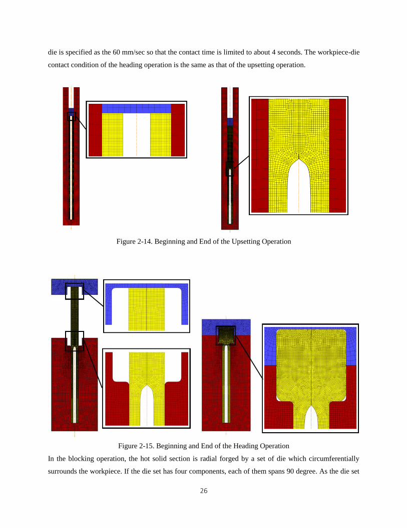
26
die is specified as the 60 mm/sec so that the contact time is limited to about 4 seconds. The workpiece-die
contact condition of the heading operation is the same as that of the upsetting operation.
Figure 2-14. Beginning and End of the Upsetting Operation
Figure 2-15. Beginning and End of the Heading Operation
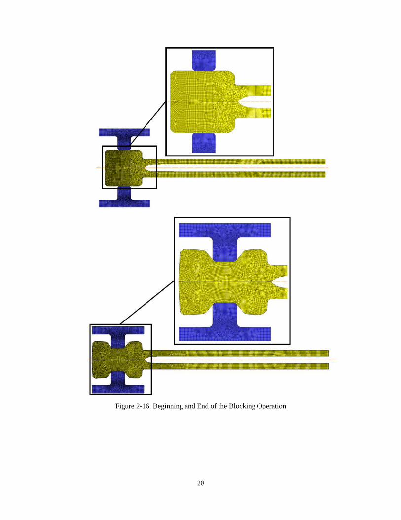
In the blocking operation, the hot solid section is radial forged by a set of die which circumferentially
surrounds the workpiece. If the die set has four components, each of them spans 90 degree. As the die set
27
moves towards the center line, the hot metal under the pressure of the die is compressed radially and
stretched axially. As a result, the diameter in the middle of the hot solid section decrease and the length of
this section grows. It should be noted that increasing the number of radial dies increases the complexity of
the process. Blocking operation using two dies (top and bottom) will be the simplest alternative to
implement in conventional forging machines.
Figure 2-16 shows the meshed parts and their configuration at the beginning and the end of the blocking
peration. In this simulation, two ends of the workpiece are not fixed and therefore growth of axial length
due to the diameter reduction is not constrained. As a result, the diameters of the two newly forged
flanges grow by a small amount. If compressive forces can be axially applied to the workpiece when it is
radial forged, it is believed that increase in the diameters of the two newly forged flanges will be larger.
In order to eliminate a lap or lobe caused by the gap between die components, the workpiece could be
rotated resulting in a metal flow in hoop direction. Therefore, a 3D FEM model is worthy of consideration,
though the radial forging can be roughly treated as a 2D axisymmetric problem. The remesh criteria,
contact condition, the movement of the primary die of this operation are same as those of previous
operations.
In the finishing operation, the workpiece is positioned inside the impression die and is forged in a net
shape way. The goal of this operation is to make dimensions of the workpiece closer to the final
dimensions and to modify the draft angle and fillet radius. Figure 2-17 shows the meshed parts and their
configuration at the beginning and the end of the heading operation.
28
Figure 2-16. Beginning and End of the Blocking Operation
29
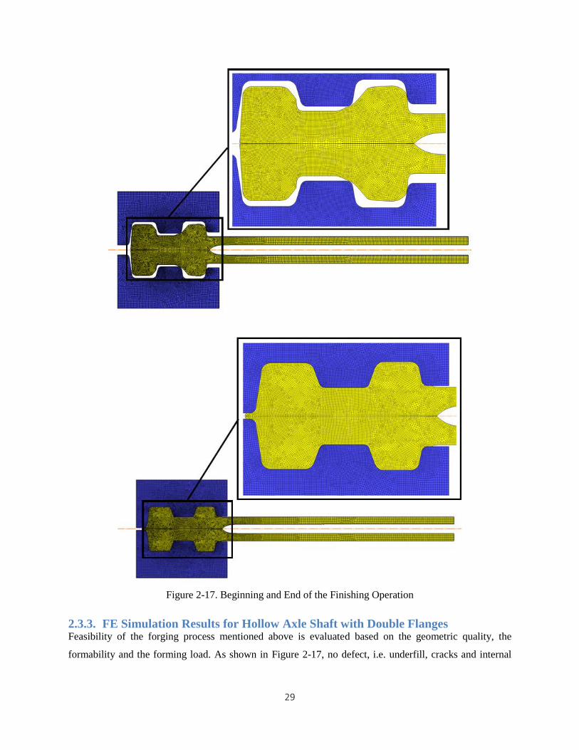
Figure 2-17. Beginning and End of the Finishing Operation
2.3.3. FE Simulation Results for Hollow Axle Shaft with Double Flanges Feasibility of the forging process mentioned above is evaluated based on the geometric quality, the
formability and the forming load. As shown in Figure 2-17, no defect, i.e. underfill, cracks and internal

30
void, is found in the final part. The cold section remains straight and hollow. The flash at the end of the
workpiece and a small step at the root of the right flange can be trimmed off by machining.
The maximum strain of the final part is a critical indicator of the formability. As is shown in Figure 2-18,
a maximum strain of 5.58, occurs at the center of the head where maximum temperature coincides. This
value may be acceptable for hot forging. Due to the moderate ratio of the flange diameter to the shaft
body diameter, the maximum strain is not as severe as that of the hollow axle shaft. Therefore feasibility
of this process and the product quality should be less impaired by the maximum strain and strain
concentration issues. It should also be noted that in the finishing operation a hole will be drilled at the
center of the solid section. By so doing the region with concentrated strain will be eliminated. It is also
found out from Figure 2-18 that strain at the fillets located in connection between two flanges is next to
the maximum strain in the center of the head. Therefore the heat dissipation from the workpiece to the die
which causes reduction in the temperature of the superficial layer of the workpiece should be minimized.
Shortening the contact time, elevating die temperature are options which are worthy of consideration.
Another observation from the strain distribution is that deformation of two newly forged flanges is much
lower than that of the connection body between two flanges. That is consistent with a small amount of
increase in the flange diameter during the blocking operation. The flange diameter mainly relies on the
heading operation. In order to gain more radial growth of the flange, compressive forces acting on ends of
the workpiece should be introduced so that the material of the two flanges is axially compressed and
radially extended.
Another indicator of the feasibility of the process is the forming load attained. Figure 2-19 shows load-
stroke curves for the operations I, II, III, and IV. The forming load of the upsetting operation keeps
increasing until the stroke reaches 15 mm and then enters a plateau. The plateau comes to an end at a
stroke of 70 mm and then the forming load steeply increases. As the central hole is gradually filled by the
hot material, the cross sectional area of hot material contacting the top die increases. That causes the first
ramp of the forming load. Deformation of the warm material is believed to be responsible for the second
steep ramp of the load. Maximum forming load of the upsetting operation is about 210 tons. The forming
load of the heading operation increases slowly at the beginning and soars at the end. The forming load
during the heading operation reaches a maximum of 340 tons at the stroke of 275 mm. The leap of the
forming load at the end of the heading operation is attributed to filling of the die corners by the material.
The forming load of the blocking operation has a peak value 230 tons at the stroke of 1.5 mm. The slight
reduction of the forming load after the peak maybe results from decrease in the diameter and the average
flow of deformed material. Maximum forming load throughout the process occurs in the finishing
operation, which reaches the 600 tons at the end of the finishing operation. This maximum load can be

31
lowered by optimizing the geometries of the die or leaving a small gap which will be evened out during
machining. In summary, the range of forming loads throughout the process is within the capacity of the
press commonly used in the forging industry. Therefore the process is feasible in the sense of the forming
load.
Figure 2-18. Strain Distribution of the Final Part
I. Upsetting II. Heading
III. Blocking IV. Finishing
Figure 2-19. Load-Stroke Curve
32
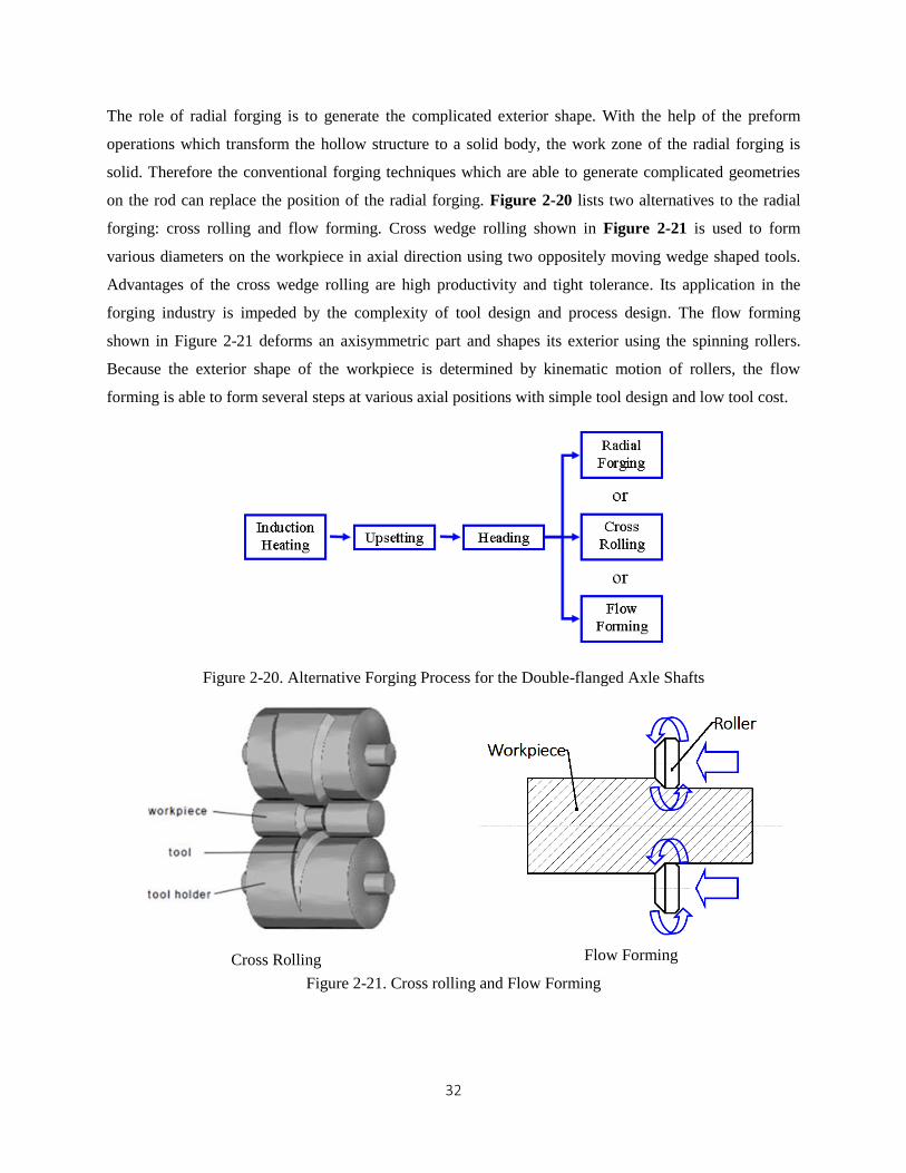
The role of radial forging is to generate the complicated exterior shape. With the help of the preform
operations which transform the hollow structure to a solid body, the work zone of the radial forging is
solid. Therefore the conventional forging techniques which are able to generate complicated geometries
on the rod can replace the position of the radial forging. Figure 2-20 lists two alternatives to the radial
forging: cross rolling and flow forming. Cross wedge rolling shown in Figure 2-21 is used to form
various diameters on the workpiece in axial direction using two oppositely moving wedge shaped tools.
Advantages of the cross wedge rolling are high productivity and tight tolerance. Its application in the
forging industry is impeded by the complexity of tool design and process design. The flow forming
shown in Figure 2-21 deforms an axisymmetric part and shapes its exterior using the spinning rollers.
Because the exterior shape of the workpiece is determined by kinematic motion of rollers, the flow
forming is able to form several steps at various axial positions with simple tool design and low tool cost.
Figure 2-20. Alternative Forging Process for the Double-flanged Axle Shafts
Cross Rolling Flow Forming
Figure 2-21. Cross rolling and Flow Forming

33
Chapter 3
Development of Forging Process to Produce Hollow Main Shaft
This chapter presents i) non-isothermal forging of a hollow gearbox main shaft where wall thickness is
controlled by introducing a mandrel during upsetting stage. ii) a new forging process which combines the
non-isothermal forging process with radial forging or upset radial forging to produce a double-flanged
main shaft. The forged shafts are evaluated based on formability and the forming load. Characteristics of
the two forging sequences are discussed individually and compared.
3.1. Optimization of Die Design for Thin Walled Main Shaft and Solution to
the Wall Thickening Problem
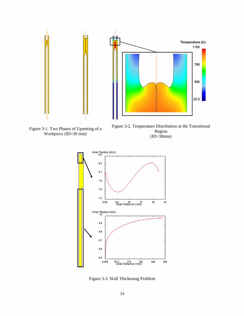
When a hollow main shaft with a large ID/OD is fabricated by the non-isothermal forging process,
folding shown in Figure 3-1 and Figure 3-2 usually occurs at the transitional regions before a sufficiently
large solid section in the middle of the workpiece is created. The premature folding prevents the material
from filling the central hole.
Deformation of the workpiece with a large ID/OD during the upsetting operation can be divided into two
phases. First, the central hole is fully closed. Second, folding occurs at the top transitional region, as
depicted in Figure 3-1. The premature folding during the upsetting operation can be explained by the
inhomogeneous temperature distribution in the transitional region. As shown in Figure 3-2, the folding at
the top transitional region is attributed to a high temperature gradient between the hot material (800oC)
and the cold material.
Wall thickening is another problem which needs to be addressed as it may affect the quality of the product.
Figure 3-3 shows distribution of the inner radius along axis when a workpiece with the inner radius of 10
mm is upset. It is found out that the inner radius of the hollow section on the top fluctuates around 8 mm
and falls in the range from 7.6 mm to 8.3 mm. However, the inner radius of the hollow section at the
bottom varies from 9.5 mm to 10 mm. Obviously, the wall on the top is thicker and more non-uniform
than the wall at the bottom. The wall thickening problem is believed to result from change in the stress
state by the inappreciable shear stress between the die and the workpiece. Compared with the material in
the bottom hollow section which barely moves with respect to the die, the metal flow velocity at the top
hollow section is not negligible. Therefore, the magnitude of the shear stress exerted on the workpiece
material rises and elevates the effective stress that the top hollow section is subjected to. As a result, the
top hollow section yields and wall thickness increases.
34
Figure 3-1. Two Phases of Upsetting of a
Workpiece (ID=30 mm)
Figure 3-2. Temperature Distribution at the Transitional
Region
(ID=30mm)
Figure 3-3. Wall Thickening Problem
35
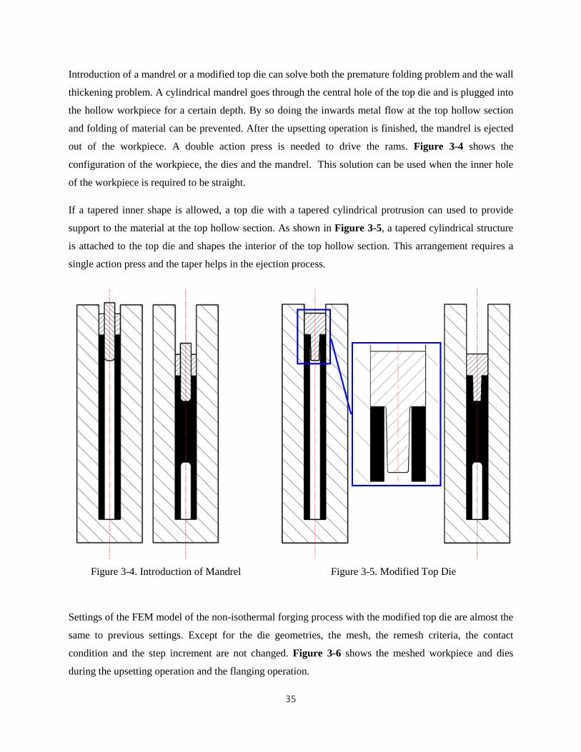
Introduction of a mandrel or a modified top die can solve both the premature folding problem and the wall
thickening problem. A cylindrical mandrel goes through the central hole of the top die and is plugged into
the hollow workpiece for a certain depth. By so doing the inwards metal flow at the top hollow section
and folding of material can be prevented. After the upsetting operation is finished, the mandrel is ejected
out of the workpiece. A double action press is needed to drive the rams. Figure 3-4 shows the
configuration of the workpiece, the dies and the mandrel. This solution can be used when the inner hole
of the workpiece is required to be straight.
If a tapered inner shape is allowed, a top die with a tapered cylindrical protrusion can used to provide
support to the material at the top hollow section. As shown in Figure 3-5, a tapered cylindrical structure
is attached to the top die and shapes the interior of the top hollow section. This arrangement requires a
single action press and the taper helps in the ejection process.
Figure 3-4. Introduction of Mandrel Figure 3-5. Modified Top Die
Settings of the FEM model of the non-isothermal forging process with the modified top die are almost the
same to previous settings. Except for the die geometries, the mesh, the remesh criteria, the contact
condition and the step increment are not changed. Figure 3-6 shows the meshed workpiece and dies
during the upsetting operation and the flanging operation.
36
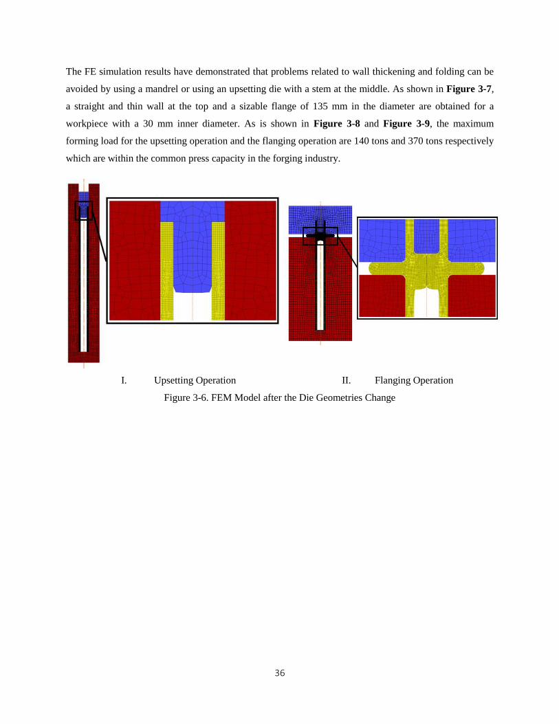
The FE simulation results have demonstrated that problems related to wall thickening and folding can be
avoided by using a mandrel or using an upsetting die with a stem at the middle. As shown in Figure 3-7,
a straight and thin wall at the top and a sizable flange of 135 mm in the diameter are obtained for a
workpiece with a 30 mm inner diameter. As is shown in Figure 3-8 and Figure 3-9, the maximum
forming load for the upsetting operation and the flanging operation are 140 tons and 370 tons respectively
which are within the common press capacity in the forging industry.
I. Upsetting Operation II. Flanging Operation
Figure 3-6. FEM Model after the Die Geometries Change

37
Figure 3-7. Final Part after Introduction of the Mandrel
Figure 3-8. Load-Stroke of the Upsetting Operation Figure 3-9. Load-Stroke of the Flanging Operation
38
3.2. Forging Process of Hollow Main Shaft with Double Flanges
In the previous chapter, a forging process which combines the non-isothermal forging and radial forging
to produce an axle shaft with double flanges was discussed. Some power transmission shafts may have
more than one flange or other additional features, i.e., steps or undercut in the middle of the shafts. This
section discusses a potential forging scheme for main shaft with double flanges. Although the forging
process still combines the non-isothermal forging and the radial forging, the heating zone and die
geometries are adapted to the preform shape and the final shape. The feasibility of the process is
evaluated based on formability and the forming load.
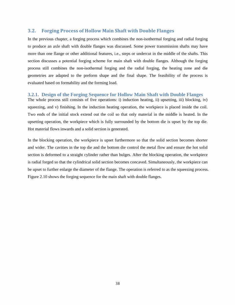
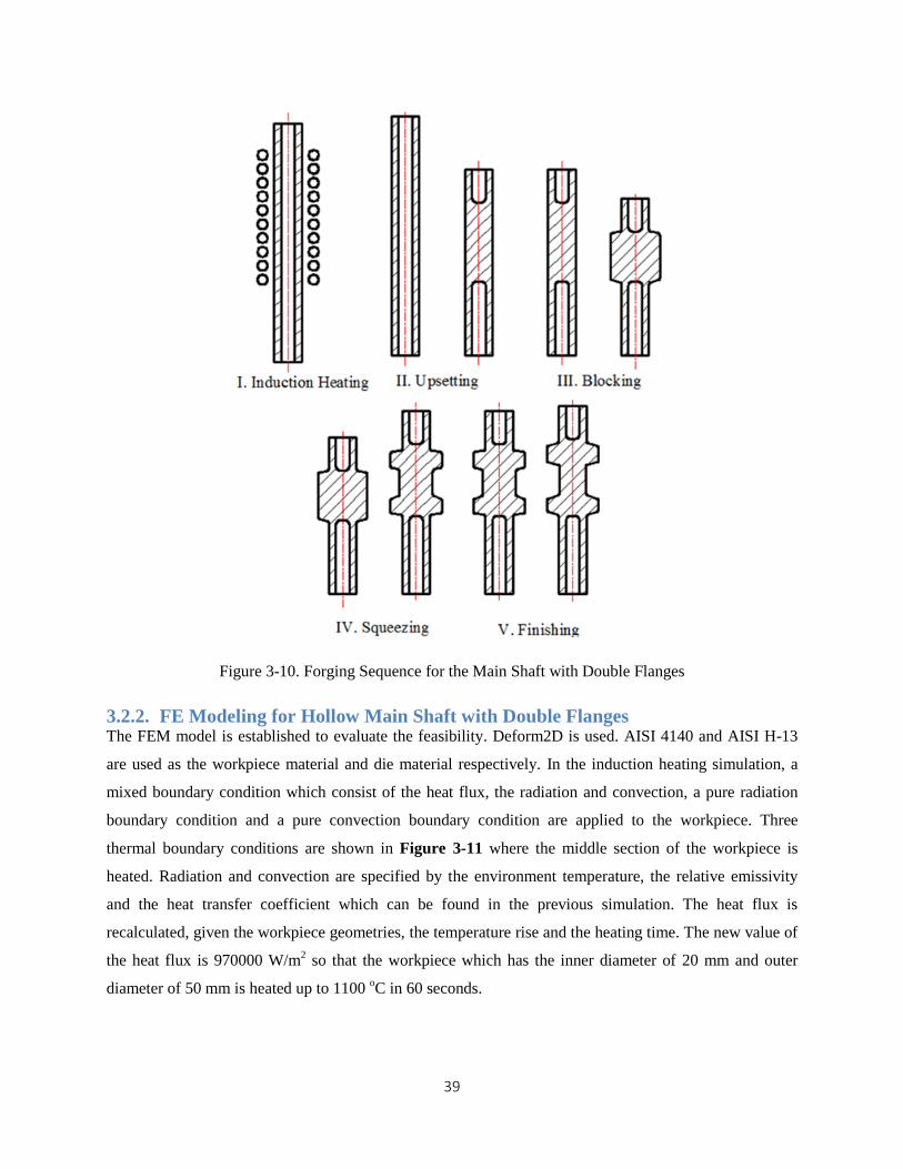
3.2.1. Design of the Forging Sequence for Hollow Main Shaft with Double Flanges The whole process still consists of five operations: i) induction heating, ii) upsetting, iii) blocking, iv)
squeezing, and v) finishing. In the induction heating operation, the workpiece is placed inside the coil.
Two ends of the initial stock extend out the coil so that only material in the middle is heated. In the
upsetting operation, the workpiece which is fully surrounded by the bottom die is upset by the top die.
Hot material flows inwards and a solid section is generated.
In the blocking operation, the workpiece is upset furthermore so that the solid section becomes shorter
and wider. The cavities in the top die and the bottom die control the metal flow and ensure the hot solid
section is deformed to a straight cylinder rather than bulges. After the blocking operation, the workpiece
is radial forged so that the cylindrical solid section becomes concaved. Simultaneously, the workpiece can
be upset to further enlarge the diameter of the flange. The operation is referred to as the squeezing process.
Figure 2.10 shows the forging sequence for the main shaft with double flanges.
39
Figure 3-10. Forging Sequence for the Main Shaft with Double Flanges
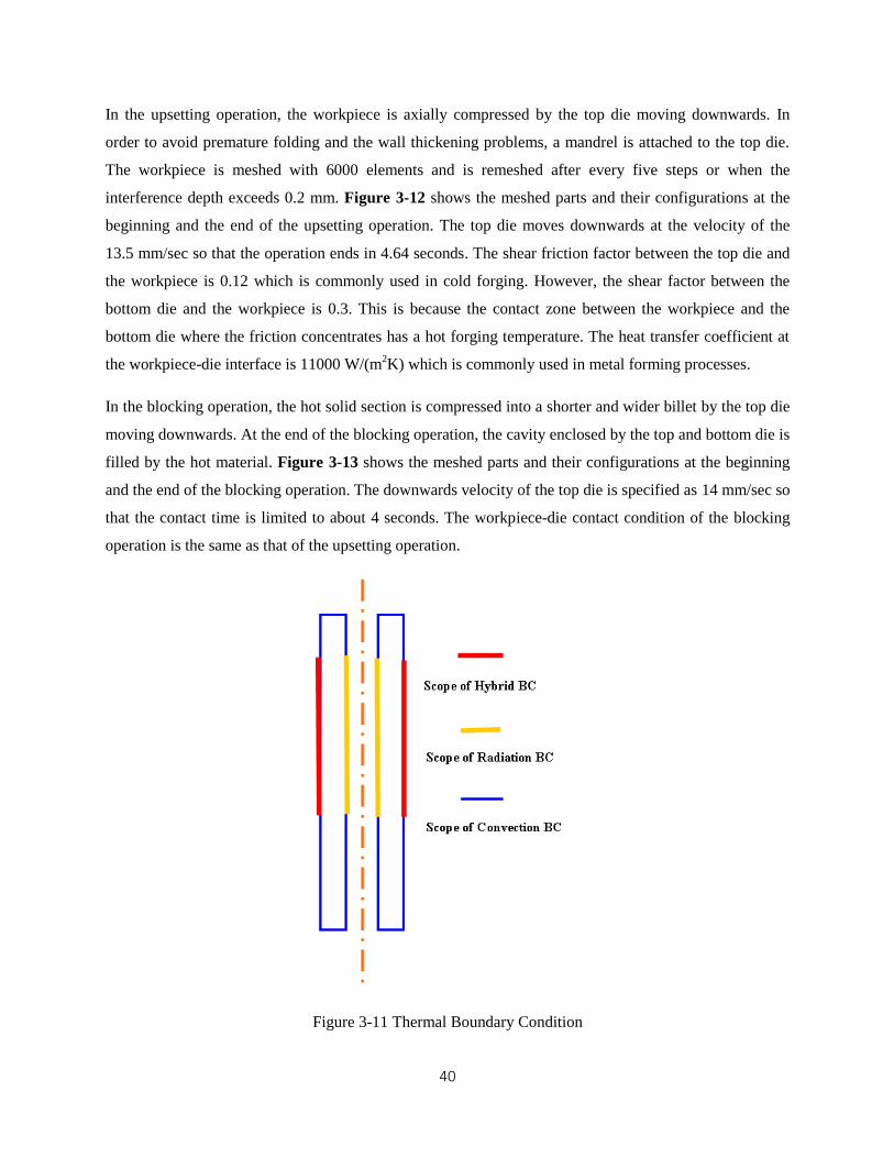
3.2.2. FE Modeling for Hollow Main Shaft with Double Flanges The FEM model is established to evaluate the feasibility. Deform2D is used. AISI 4140 and AISI H-13
are used as the workpiece material and die material respectively. In the induction heating simulation, a
mixed boundary condition which consist of the heat flux, the radiation and convection, a pure radiation
boundary condition and a pure convection boundary condition are applied to the workpiece. Three
thermal boundary conditions are shown in Figure 3-11 where the middle section of the workpiece is
heated. Radiation and convection are specified by the environment temperature, the relative emissivity
and the heat transfer coefficient which can be found in the previous simulation. The heat flux is
recalculated, given the workpiece geometries, the temperature rise and the heating time. The new value of
the heat flux is 970000 W/m2 so that the workpiece which has the inner diameter of 20 mm and outer
diameter of 50 mm is heated up to 1100 oC in 60 seconds.
40
In the upsetting operation, the workpiece is axially compressed by the top die moving downwards. In
order to avoid premature folding and the wall thickening problems, a mandrel is attached to the top die.
The workpiece is meshed with 6000 elements and is remeshed after every five steps or when the
interference depth exceeds 0.2 mm. Figure 3-12 shows the meshed parts and their configurations at the
beginning and the end of the upsetting operation. The top die moves downwards at the velocity of the
13.5 mm/sec so that the operation ends in 4.64 seconds. The shear friction factor between the top die and
the workpiece is 0.12 which is commonly used in cold forging. However, the shear factor between the
bottom die and the workpiece is 0.3. This is because the contact zone between the workpiece and the
bottom die where the friction concentrates has a hot forging temperature. The heat transfer coefficient at
the workpiece-die interface is 11000 W/(m2K) which is commonly used in metal forming processes.
In the blocking operation, the hot solid section is compressed into a shorter and wider billet by the top die
moving downwards. At the end of the blocking operation, the cavity enclosed by the top and bottom die is
filled by the hot material. Figure 3-13 shows the meshed parts and their configurations at the beginning
and the end of the blocking operation. The downwards velocity of the top die is specified as 14 mm/sec so
that the contact time is limited to about 4 seconds. The workpiece-die contact condition of the blocking
operation is the same as that of the upsetting operation.
Figure 3-11 Thermal Boundary Condition
41
Figure 3-12. Upsetting Operation
Figure 3-13. Blocking Operation
42
In the squeezing operation, the hot solid section is radial forged and its diameter is locally reduced.
Figure 3-14 shows the meshed parts and their configurations at the beginning and the end of the
squeezing operation (radial forging). The die which moves radially compresses the middle of the solid
section and the material in the middle is displaced axially. As a result, the hot solid section is deformed to
a concave shape. In order to encourage growth of diameter of two flanges, the axial compressive forces
can be applied to the two ends of the workpiece. Figure 3-15 shows the meshed parts at the beginning
and the end of squeezing operation (upset radial forging). Two punches in blue which move axially
compress the workpiece and the die in red which moves radially generates a dent in the solid section. The
cavity of the punch at the left hand side accommodates the tubular workpiece and makes it undeformed.
The die land of the left punch guides the growth of flange in the radial direction and maximizes the flange
diameter. The remesh criteria, contact condition, and the movement of the primary die of this operation
are same as those of previous operations.
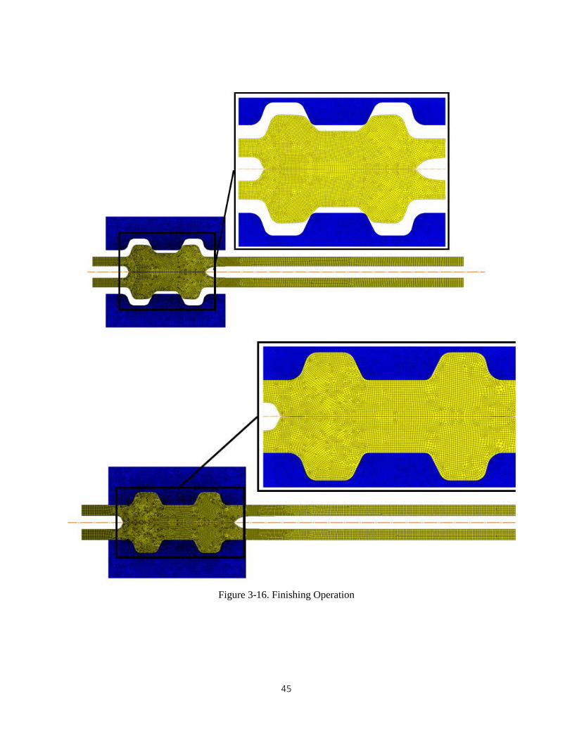
In the finishing operation, the workpiece is impression forged so that the final part satisfies geometric and
dimensional requirement of the product. Impression forging may not be needed as the shaft will be
machined to the final dimensions. Figure 3-16 shows the meshed parts and their configuration at the
beginning and the end of the finishing operation.
43
Figure 3-14. Squeezing Operation by Radial Forging
44
Figure 3-15. Squeezing Operation by Upset Radial Forging
45
Figure 3-16. Finishing Operation

46
3.2.3. FE Simulation Results for Hollow Main Shaft with Double Flanges As is mentioned above, the upset radial forging process encourages the radial growth of the flange and is
able to yield wider flange than the radial forging. Figure 3-17 shows the different flange diameters of the
workpiece produced by radial forging and upset radial forging. Radial forging and upset radial forging use
the same preform as the initial stock. The flange diameter generated by radial forging is 87 mm. Upset
radial forging can increase the flange diameter to 98 mm. It is verified by FEM simulation that upset
radial forging has the advantage of creating the large flange diameter. The disadvantages of upset radial
forging, however, are additional dies and more advanced forging machines with capabilities to provide
both the radial force and the axial compressive force. Because radial forging is unable to enlarge the
flange diameter by a large amount, the preform yielded by the blocking operation must have a wide
enough solid section to compensate the insufficient increase in the flange diameter during radial forging.
Maximum strain and forming loads are examined to evaluate the feasibility of the forging process for the
main shaft with double flanges. Figure 3-18 shows that the maximum strain is 5.5. The maximum strain
occurs at the center of the solid section, because the material at the center is most radially compressed.
Further investigation is needed to determine whether this maximum strain is beyond the formability of hot
forging and the internal defects are caused by the strain concentration. If a hole will be drilled at the
center of the solid region, concentrated strain will be eliminated.
Forming loads of the four operations have similar trends and magnitudes to those which are applied in the
production of the axle shaft with double flanges. As is shown in Figure 3-19, maximum forming loads of
I, II and III are all below 250 tons. Figure 3-19 also shows that the finish operation requires a press
capacity of about 600 tons. As discussed earlier, impression forging operation may not be needed as the
part will be machined to final dimensions.

47
Figure 3-17. Flange Diameter of the Workpiece by Radial Forging (left) and Upset Radial Forging (right)
Figure 3-18. Strain Distribution of the Main Shaft with Double Flanges

48
I. Upsetting II. Blocking
III. Squeezing IV. Finishing
Figure 3-19. Load-Stroke of the Forging Process for the Main Shaft with Double Flanges
49
Chapter 4
Development of Forging Process to Produce Hollow Pinion Gear Shaft
In the previous investigation, a forging process which combines the open-die hollow extrusion with the
non-isothermal forging to fabricate hollow pinion gear shaft with a step was presented [10]. To increase
dimensional accuracy of the forged hollow shaft, this chapter explores other forging techniques, i.e.
trapped-die mandrel and trapped die plug, which can be incorporated in the non-isothermal forging
sequence.
4.1. Sequence 1: Extrusion Stage before the Non-isothermal Forging Process
In this forging sequence, the trapped-die mandrel type hollow extrusion is placed in front of the non-
isothermal forging, Figure 4-1. In the extrusion operation, the die reduces the outer diameter of the
workpiece for some length. The interior of the workpiece is fully supported by the mandrel which moves
with the workpiece and the inner diameter remains constant. The subsequent non-isothermal forging
process is also composed of the induction heat operation, the upsetting operation and the coning operation.
The induction operation locally heats the workpiece and creates the spatially-varying flow stress. The
upsetting operation transforms the hollow structure into a solid rod by compressing the workpiece. Due to
the stepped shaft geometry, inner geometries of the bottom die have two different diameters. In the coning
operation, the solid section is compressed by a die with a conical cavity to produce a conical head. Figure
4-1 shows the forging sequence discussed above.

50
Figure 4-1. the First Forging Sequence for the Pinion Gear Shaft
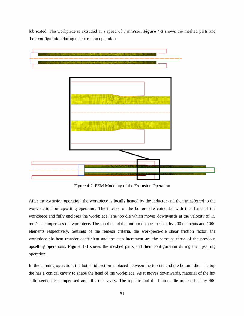
4.1.1. FE Modeling of Sequence 1 In the extrusion operation, the workpiece is extruded through a die which fully covers the workpiece. As
the workpiece is extruded, a mandrel which supports the workpiece from inside moves as well. As a result,
the outer diameter of the workpiece is reduced and the inner diameter is unchanged. The workpiece is
initially meshed by about 4500 elements and is remeshed every ten steps or when the interference depth is
over 0.22 mm. Because the extrusion is conducted at room temperature, the heat transfer mode is not
activated in the simulation and the dies are not meshed. The outer diameter is reduced from 36 mm to 32
mm and hence the diameter reduction is 11%. The semi die angle is 11 oC which is commonly used in
extrusion and drawing. Although the extrusion temperature in this process is roughly the room
temperature, warm and hot extrusion can be used to achieve larger diameter reduction. The workpiece-die
shear friction factor is 0.12 which is commonly used in the cold forging simulation if the die is well
51
lubricated. The workpiece is extruded at a speed of 3 mm/sec. Figure 4-2 shows the meshed parts and
their configuration during the extrusion operation.
Figure 4-2. FEM Modeling of the Extrusion Operation
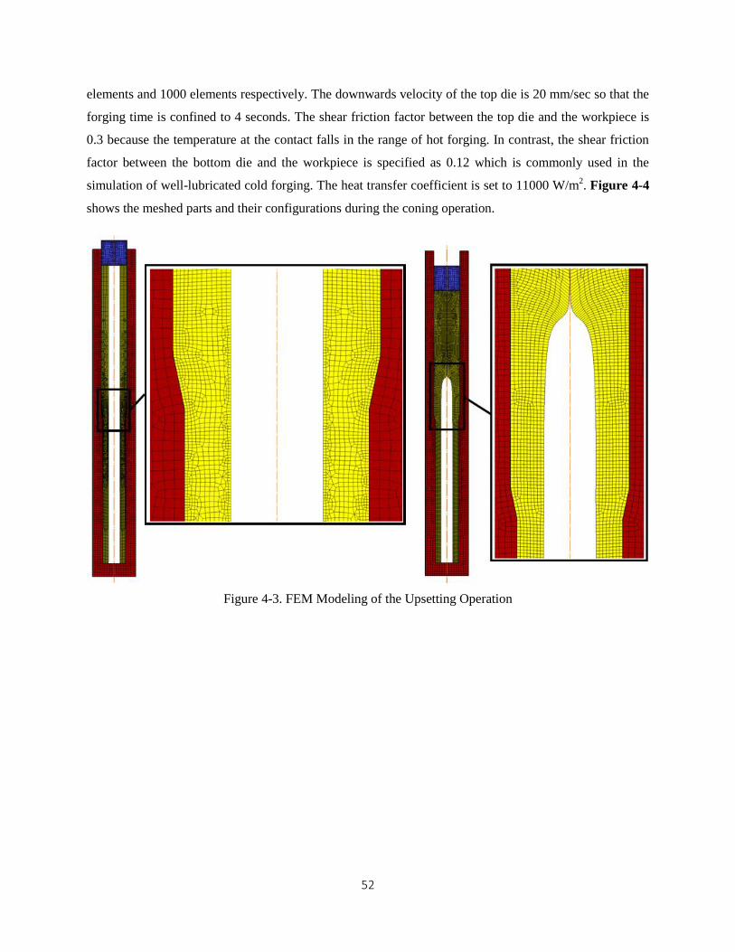
After the extrusion operation, the workpiece is locally heated by the inductor and then transferred to the
work station for upsetting operation. The interior of the bottom die coincides with the shape of the
workpiece and fully encloses the workpiece. The top die which moves downwards at the velocity of 15
mm/sec compresses the workpiece. The top die and the bottom die are meshed by 200 elements and 1000
elements respectively. Settings of the remesh criteria, the workpiece-die shear friction factor, the
workpiece-die heat transfer coefficient and the step increment are the same as those of the previous
upsetting operations. Figure 4-3 shows the meshed parts and their configuration during the upsetting
operation.
In the conning operation, the hot solid section is placed between the top die and the bottom die. The top
die has a conical cavity to shape the head of the workpiece. As it moves downwards, material of the hot
solid section is compressed and fills the cavity. The top die and the bottom die are meshed by 400
52
elements and 1000 elements respectively. The downwards velocity of the top die is 20 mm/sec so that the
forging time is confined to 4 seconds. The shear friction factor between the top die and the workpiece is
0.3 because the temperature at the contact falls in the range of hot forging. In contrast, the shear friction
factor between the bottom die and the workpiece is specified as 0.12 which is commonly used in the
simulation of well-lubricated cold forging. The heat transfer coefficient is set to 11000 W/m2. Figure 4-4
shows the meshed parts and their configurations during the coning operation.
Figure 4-3. FEM Modeling of the Upsetting Operation
53
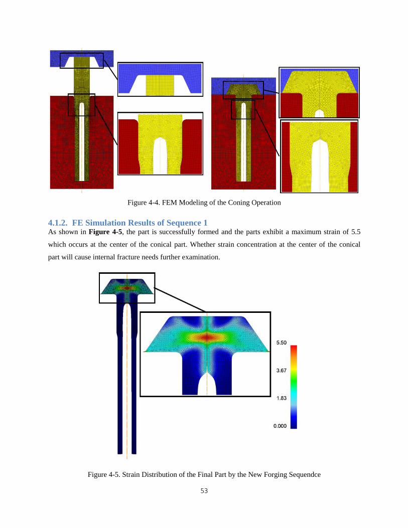
Figure 4-4. FEM Modeling of the Coning Operation
4.1.2. FE Simulation Results of Sequence 1 As shown in Figure 4-5, the part is successfully formed and the parts exhibit a maximum strain of 5.5
which occurs at the center of the conical part. Whether strain concentration at the center of the conical
part will cause internal fracture needs further examination.
Figure 4-5. Strain Distribution of the Final Part by the New Forging Sequendce

54
4.2. Sequence2 : Extrusion Stage in the middle of the Non-isothermal Forging
Process
In the second forging sequence, the mandrel type extrusion is replaced by a plug-type and it is added
between the upsetting operation and the coning operation. Figure 4-6 shows the second sequence for the
hollow pinion gear shaft. After the workpiece is upset, the step on the tubular body is shaped by a plug
type hollow extrusion. The outer diameter is reduced for a certain length and the inner diameter is
smoothed out with the aid of a plug.
Figure 4-6. the Second Forging Sequence for the Pinion Gear Shaft
Because the FEM modeling of the induction heating operation, the upsetting operation, and the conning
operations are similar to those in the first sequence, modeling parameters and procedures are not repeated
here. The FEM modeling of the extrusion operation is presented in details below. In the extrusion
operation, a fixed plug is placed inside the workpiece and shape the interior of the workpiece as it is
extruded from the die. The workpiece is remeshed every ten steps or when the interference depth is over
55
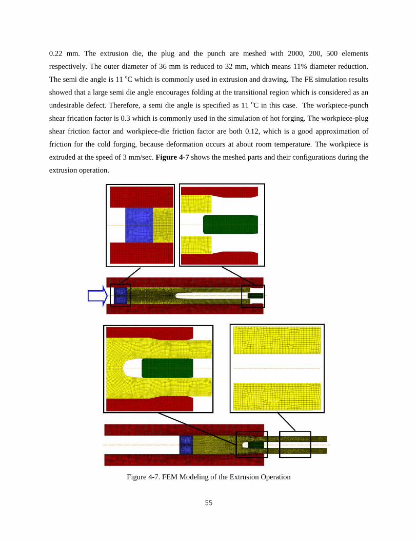
0.22 mm. The extrusion die, the plug and the punch are meshed with 2000, 200, 500 elements
respectively. The outer diameter of 36 mm is reduced to 32 mm, which means 11% diameter reduction.
The semi die angle is 11 oC which is commonly used in extrusion and drawing. The FE simulation results
showed that a large semi die angle encourages folding at the transitional region which is considered as an
undesirable defect. Therefore, a semi die angle is specified as 11 oC in this case. The workpiece-punch
shear frication factor is 0.3 which is commonly used in the simulation of hot forging. The workpiece-plug
shear friction factor and workpiece-die friction factor are both 0.12, which is a good approximation of
friction for the cold forging, because deformation occurs at about room temperature. The workpiece is
extruded at the speed of 3 mm/sec. Figure 4-7 shows the meshed parts and their configurations during the
extrusion operation.
Figure 4-7. FEM Modeling of the Extrusion Operation
56
Advantages of the second forging sequence over the first forging sequence are as follow. First, the bottom
die of the upsetting operation has a simpler interior geometry, because the workpiece for upsetting is
straight and has no steps. Second, the extrusion die of the second forging sequence is shorter because the
workpiece is shortened after the hollow structure is transformed to a solid section. A shorter die leads to a
reduced fabrication difficulties and tool cost. Third, the final part produced by the second sequence has a
tighter tolerance of the inner diameter because the plug in the extrusion operation irons out the interior
and only the coning operation is left after this stage. It should be noted that the deformation during the
coning operation may have an influence on the tolerance of the final part.
In sequence 1, both upsetting and coning operations are implemented after the inner diameter is
smoothened by the mandrel type extrusion. Therefore, the deformation during the two operations may
adversely affects the dimensional accuracy of the inner diameter. The first sequence also has advantages
over the second one. Because the cold extrusion operation in the first sequence can be substituted with
warm or hot extrusion, a higher diameter reduction can be achieved by the first sequence. However, warm
or hot extrusion cannot be introduced to the second sequence, because the coning operation which follows
the extrusion operation requires a non-uniform temperature field to locally deform the workpiece.

57
Chapter 5
Application of the Non-isothermal Forging Process to the Aluminum billet
In order to achieve weight reduction in the power train of the automobile, various types of high strength
aluminum alloys are developed for parts in the power train. The high strength aluminum alloy has
advantages of good formability, excellent machinability, exceptional corrosion resistance and high
specific strength. Due to strength requirements, however, most components used in power transmission
are made from steels. In the course of this project, a laboratory experimental setup will be built at NCSU
to demonstrate the feasibility of the proposed concept. In this setup aluminum material will be used. This
chapter focuses on: i) the deformation characteristic of the aluminum in the upsetting operation and its
differences from that of the steel ii) evaluating the feasibility of the non-isothermal forging process of
hollow shaft from aluminum.
5.1. Comparison of the Non-isothermal Forging Process for Al and Steel
Aluminum alloy 3003, which contains about 1.25% manganese and 0.1% copper, is characterized by the
moderate strength, excellent formability and good corrosion resistance. It is widely applied in equipment
fabrication. In the material library of Deform2D, the temperature range where the flow stress of
Aluminum 3003 varies is from 20 oC to 480
oC and therefore satisfies the requirement of the non-
isothermal forging process. Hence, Aluminum 3003 is selected as the workpiece material. The process
sequence and parameters of the non-isothermal forging for Aluminum 3003 is similar to those for the
AISI 4140. As a result, the settings for FEM model of AISI4140 can be applied to the case of Aluminum
3003 after some minor adjustments, i.e. the heating power and heating time.
It is found out that aluminum exhibits different deformation pattern compared to that of steel during the
upsetting operation. Figure 5-2 and Figure 5-6 show that the length of the transitional region between the
solid and the hollow regions are different. The aluminum workpiece has a longer transitional section than
that of steel. In another words, the aluminum’s reduction rate of the inner diameter from the hollow to the
solid structure is smaller. One of the factors which affect the length of the transitional region and
reduction rate of the inner diameter is the dependence of the flow stress on the temperature. The essence
of the non-isothermal forging process is to use the inhomogeneous temperature field to create the
difference in the flow across the workpiece. A large flow stress gradient with respect to the temperature
and a wide forging temperature range are the basis of superiority of the cold material in the deformation
resistance to the hot material. If the flow stress varies a little with respect to the temperature, deformation
resistance of the cold material is no longer superior to that of the hot material. The forming load used to
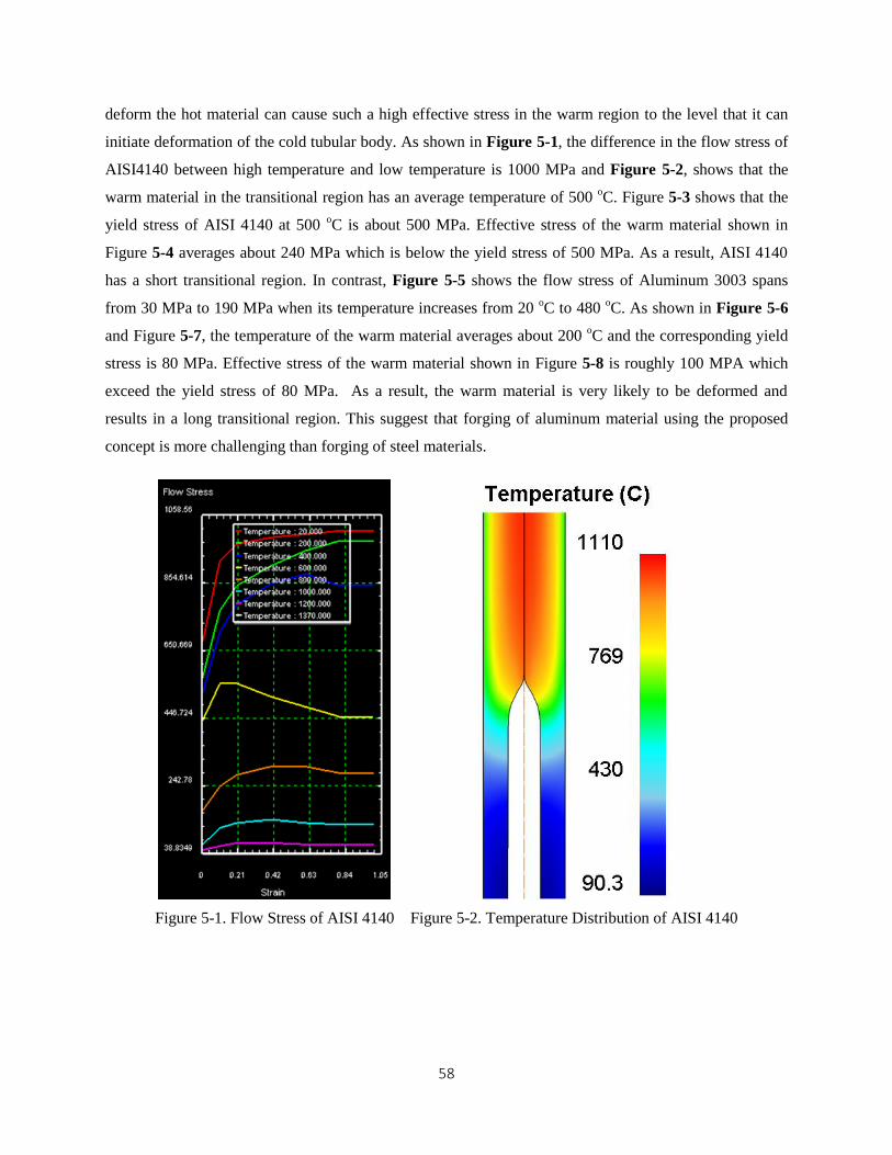
58
deform the hot material can cause such a high effective stress in the warm region to the level that it can
initiate deformation of the cold tubular body. As shown in Figure 5-1, the difference in the flow stress of
AISI4140 between high temperature and low temperature is 1000 MPa and Figure 5-2, shows that the
warm material in the transitional region has an average temperature of 500 oC. Figure 5-3 shows that the
yield stress of AISI 4140 at 500 oC is about 500 MPa. Effective stress of the warm material shown in
Figure 5-4 averages about 240 MPa which is below the yield stress of 500 MPa. As a result, AISI 4140
has a short transitional region. In contrast, Figure 5-5 shows the flow stress of Aluminum 3003 spans
from 30 MPa to 190 MPa when its temperature increases from 20 oC to 480
oC. As shown in Figure 5-6
and Figure 5-7, the temperature of the warm material averages about 200 oC and the corresponding yield
stress is 80 MPa. Effective stress of the warm material shown in Figure 5-8 is roughly 100 MPA which
exceed the yield stress of 80 MPa. As a result, the warm material is very likely to be deformed and
results in a long transitional region. This suggest that forging of aluminum material using the proposed
concept is more challenging than forging of steel materials.
Figure 5-1. Flow Stress of AISI 4140 Figure 5-2. Temperature Distribution of AISI 4140

59
Figure 5-3. Yield Stress of the AISI 4140 versus the
Temperature
Figure 5-4. Effective Stress
Distribution of AISI 4140
Figure 5-5. Flow Stress of Aluminum 3003 Figure 5-6. Temperature Distribution of Aluminum 3003
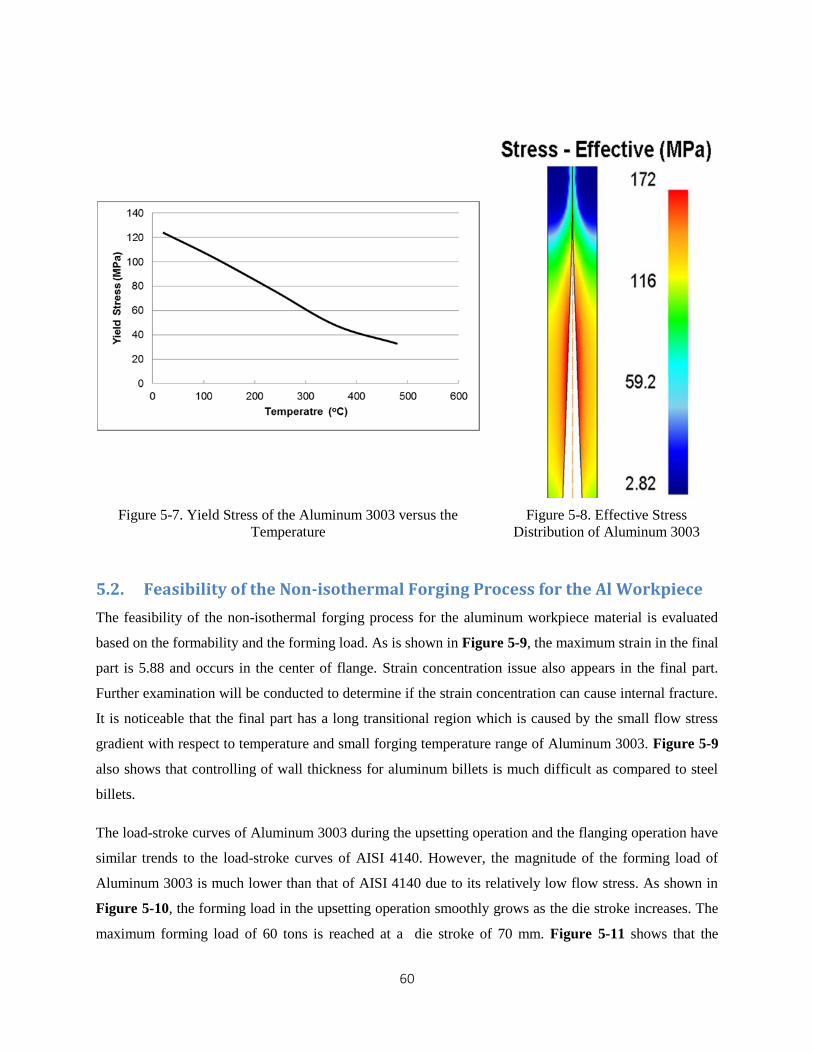
60
Figure 5-7. Yield Stress of the Aluminum 3003 versus the
Temperature
Figure 5-8. Effective Stress
Distribution of Aluminum 3003
5.2. Feasibility of the Non-isothermal Forging Process for the Al Workpiece
The feasibility of the non-isothermal forging process for the aluminum workpiece material is evaluated
based on the formability and the forming load. As is shown in Figure 5-9, the maximum strain in the final
part is 5.88 and occurs in the center of flange. Strain concentration issue also appears in the final part.
Further examination will be conducted to determine if the strain concentration can cause internal fracture.
It is noticeable that the final part has a long transitional region which is caused by the small flow stress
gradient with respect to temperature and small forging temperature range of Aluminum 3003. Figure 5-9
also shows that controlling of wall thickness for aluminum billets is much difficult as compared to steel
billets.
The load-stroke curves of Aluminum 3003 during the upsetting operation and the flanging operation have
similar trends to the load-stroke curves of AISI 4140. However, the magnitude of the forming load of
Aluminum 3003 is much lower than that of AISI 4140 due to its relatively low flow stress. As shown in
Figure 5-10, the forming load in the upsetting operation smoothly grows as the die stroke increases. The
maximum forming load of 60 tons is reached at a die stroke of 70 mm. Figure 5-11 shows that the
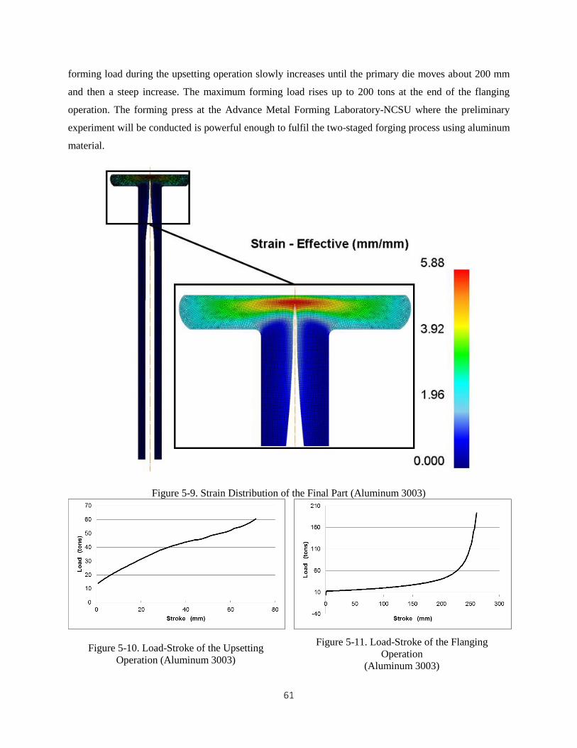
61
forming load during the upsetting operation slowly increases until the primary die moves about 200 mm
and then a steep increase. The maximum forming load rises up to 200 tons at the end of the flanging
operation. The forming press at the Advance Metal Forming Laboratory-NCSU where the preliminary
experiment will be conducted is powerful enough to fulfil the two-staged forging process using aluminum
material.
Figure 5-9. Strain Distribution of the Final Part (Aluminum 3003)
Figure 5-10. Load-Stroke of the Upsetting
Operation (Aluminum 3003)
Figure 5-11. Load-Stroke of the Flanging
Operation
(Aluminum 3003)

62
Chapter 6
Induction Heating Design
6.1. Definition, application and advantage of Induction Heating
Induction heating is a method of heating the electrically conductive workpiece. The whole induction
heating system consists of the induction coil, the alternating-current (AC) power supply and the
workpiece. The alternating current from the power supply flows through the coil and generates an
alternating magnetic field surrounding the workpiece. The alternating magnetic flux induces the eddy
current in the workpiece. The current distribution within the workpiece is non-uniform due to several
electromagnetic phenomena, i) skin effect, ii) proximity effect. When the eddy current is induced in the
workpiece, the maximum value of the current density is located in the superficial layer. This
phenomenon is called the skin effect. The thickness of this layer where approximately 86% of the power
is concentrated is called the penetration depth or the reference depth. Two neighboring conductors
carrying the opposite current make the current in one conductor concentrated in the side facing the other
conductor. This phenomenon is called the proximity effect. Because the eddy current induced in the
workpiece is in the opposite direction to the coil current, the eddy current concentrates in the areas facing
the coil. The skin effect and the proximity effect both redistribute the current density within the
workpiece and cause the heat source to concentrate in the surface of the workpiece. Induction heating
relies on two mechanisms of heat generation. They are the Joule heat and the hysteresis loss. Joule heat is
generated by the eddy current in the workpiece. Hysteresis loss is caused by reversing magnetization of
the material and is proportional to the area of the hysteresis loop. Both mechanisms play roles in
induction heating of the ferromagnetic material. However, the Joule heat accounts for the majority of heat
generation. For the nonmagnetic material or ferromagnetic material above the curie point, Joule heat is
the only heat generation mechanism [1][12]. Induction heating is commonly used in preheating prior to
metalworking, heat treatment, welding and the melting. Figure 6-1 summarizes the industrial application
of induction heating.
Induction heating is increasingly popular due to the following advantages over the gas-fired and oil-fired
furnace: i) the heating rate of the induction heating is much higher than that of the furnace heating. ii) the
rapid heating leads to a significant reduction of material loss due to scaling. iii) the induction heating can
be started up more quickly than the furnace heating because the furnace contains a great amount of the
refractory material which must be heated up during the start-up. iv) the induction heating consumes less
energy than the furnace heating. When not in use, the induction power supply can be turned off because
the inductor can be restarted quickly. However, energy must be continuously supplied to the furnace to
maintain the furnace temperature during delays in the process so that long start-up can be avoided. Based
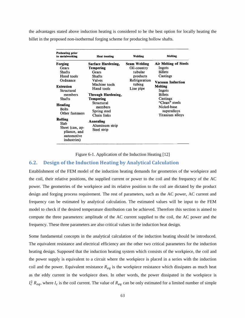
63
the advantages stated above induction heating is considered to be the best option for locally heating the
billet in the proposed non-isothermal forging scheme for producing hollow shafts.
Figure 6-1. Application of the Induction Heating [12]
6.2. Design of the Induction Heating by Analytical Calculation
Establishment of the FEM model of the induction heating demands for geometries of the workpiece and
the coil, their relative positions, the supplied current or power to the coil and the frequency of the AC
power. The geometries of the workpiece and its relative position to the coil are dictated by the product
design and forging process requirement. The rest of parameters, such as the AC power, AC current and
frequency can be estimated by analytical calculation. The estimated values will be input to the FEM
model to check if the desired temperature distribution can be achieved. Therefore this section is aimed to
compute the three parameters: amplitude of the AC current supplied to the coil, the AC power and the
frequency. These three parameters are also critical values in the induction heat design.
Some fundamental concepts in the analytical calculation of the induction heating should be introduced.
The equivalent resistance and electrical efficiency are the other two critical parameters for the induction
heating design. Supposed that the induction heating system which consists of the workpiece, the coil and
the power supply is equivalent to a circuit where the workpiece is placed in a series with the induction
coil and the power. Equivalent resistance 𝑅𝑒𝑞 is the workpiece resistance which dissipates as much heat
as the eddy current in the workpiece does. In other words, the power dissipated in the workpiece is
𝐼𝑐2 𝑅𝑒𝑞, where 𝐼𝑐 is the coil current. The value of 𝑅𝑒𝑞 can be only estimated for a limited number of simple
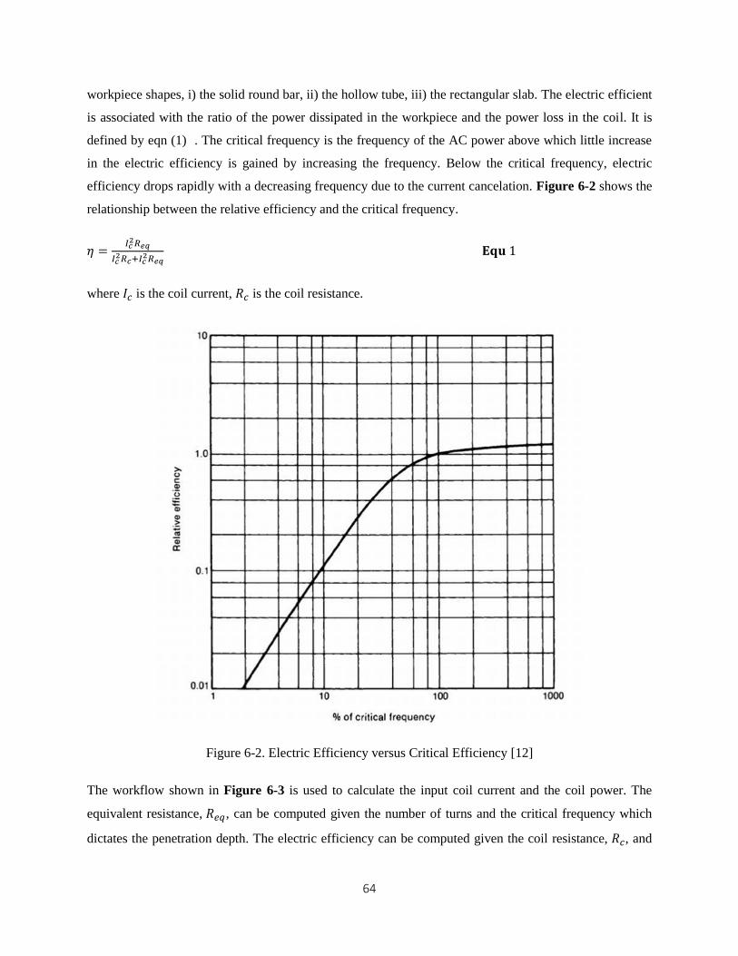
64
workpiece shapes, i) the solid round bar, ii) the hollow tube, iii) the rectangular slab. The electric efficient
is associated with the ratio of the power dissipated in the workpiece and the power loss in the coil. It is
defined by eqn (1) . The critical frequency is the frequency of the AC power above which little increase
in the electric efficiency is gained by increasing the frequency. Below the critical frequency, electric
efficiency drops rapidly with a decreasing frequency due to the current cancelation. Figure 6-2 shows the
relationship between the relative efficiency and the critical frequency.
𝜂 =𝐼𝑐
2𝑅𝑒𝑞
𝐼𝑐2𝑅𝑐+𝐼𝑐
2𝑅𝑒𝑞 𝐄𝐪𝐮 1
where 𝐼𝑐 is the coil current, 𝑅𝑐 is the coil resistance.
Figure 6-2. Electric Efficiency versus Critical Efficiency [12]
The workflow shown in Figure 6-3 is used to calculate the input coil current and the coil power. The
equivalent resistance, 𝑅𝑒𝑞, can be computed given the number of turns and the critical frequency which
dictates the penetration depth. The electric efficiency can be computed given the coil resistance, 𝑅𝑐, and
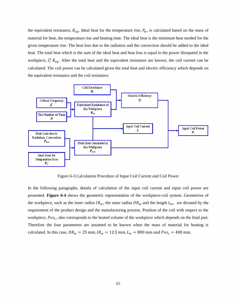
65
the equivalent resistance, 𝑅𝑒𝑞. Ideal heat for the temperature rise, 𝑃𝑤, is calculated based on the mass of
material for heat, the temperature rise and heating time. The ideal heat is the minimum heat needed for the
given temperature rise. The heat loss due to the radiation and the convection should be added to the ideal
heat. The total heat which is the sum of the ideal heat and heat loss is equal to the power dissipated in the
workpiece, 𝐼𝑐2 𝑅𝑒𝑞. After the total heat and the equivalent resistance are known, the coil current can be
calculated. The coil power can be calculated given the total heat and electric efficiency which depends on
the equivalent resistance and the coil resistance.
Figure 6-3.Calculation Procedure of Input Coil Current and Coil Power
In the following paragraphs, details of calculation of the input coil current and input coil power are
presented. Figure 6-4 shows the geometric representation of the workpiece-coil system. Geometries of
the workpiece, such as the inner radius 𝐼𝑅𝑤, the outer radius 𝑂𝑅𝑤 and the length 𝐿𝑤, are dictated by the
requirement of the product design and the manufacturing process. Position of the coil with respect to the
workpiece, 𝑃𝑜𝑠𝑐, also corresponds to the heated volume of the workpiece which depends on the final part.
Therefore the four parameters are assumed to be known when the mass of material for heating is
calculated. In this case, 𝑂𝑅𝑤 = 25 mm, 𝐼𝑅𝑤 = 12.5 mm, 𝐿𝑤 = 800 mm and 𝑃𝑜𝑠𝑐 = 400 mm.
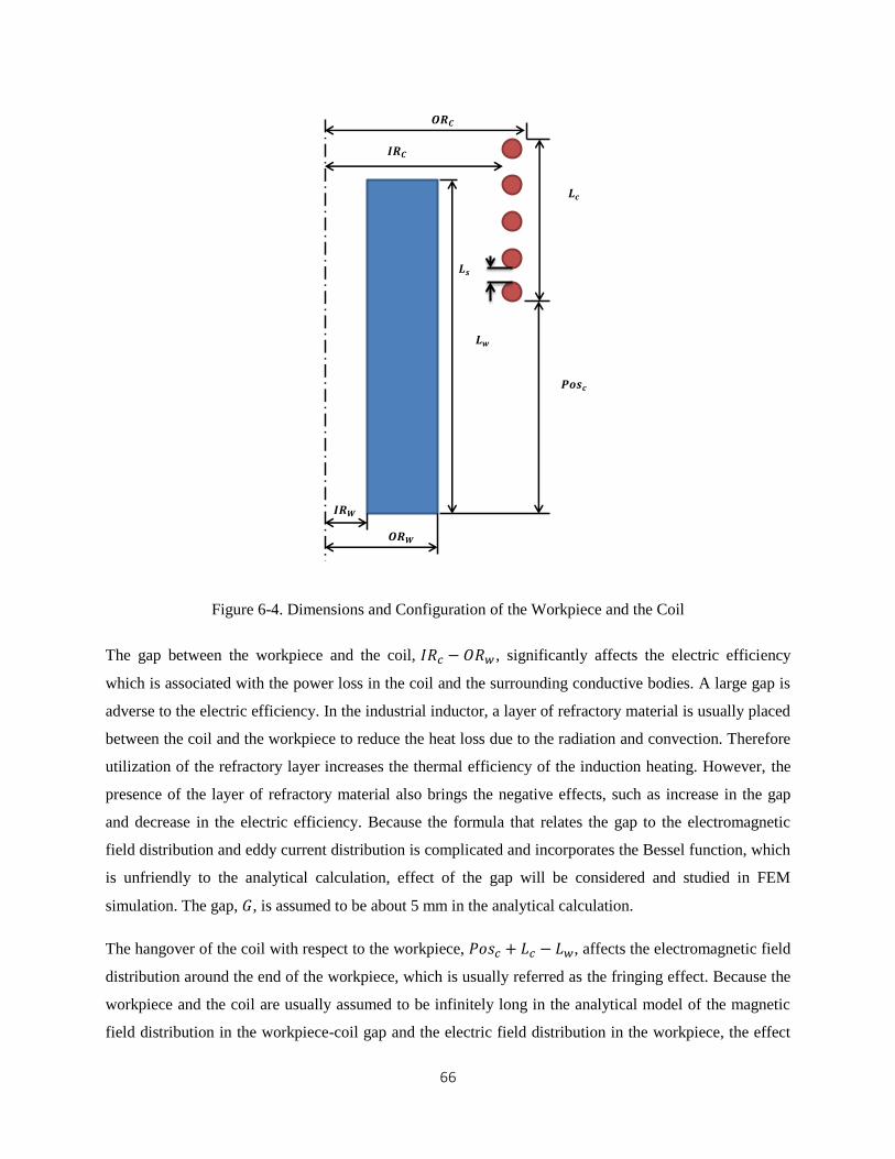
66
Figure 6-4. Dimensions and Configuration of the Workpiece and the Coil
The gap between the workpiece and the coil, 𝐼𝑅𝑐 − 𝑂𝑅𝑤 , significantly affects the electric efficiency
which is associated with the power loss in the coil and the surrounding conductive bodies. A large gap is
adverse to the electric efficiency. In the industrial inductor, a layer of refractory material is usually placed
between the coil and the workpiece to reduce the heat loss due to the radiation and convection. Therefore
utilization of the refractory layer increases the thermal efficiency of the induction heating. However, the
presence of the layer of refractory material also brings the negative effects, such as increase in the gap
and decrease in the electric efficiency. Because the formula that relates the gap to the electromagnetic
field distribution and eddy current distribution is complicated and incorporates the Bessel function, which
is unfriendly to the analytical calculation, effect of the gap will be considered and studied in FEM
simulation. The gap, 𝐺, is assumed to be about 5 mm in the analytical calculation.
The hangover of the coil with respect to the workpiece, 𝑃𝑜𝑠𝑐 + 𝐿𝑐 − 𝐿𝑤, affects the electromagnetic field
distribution around the end of the workpiece, which is usually referred as the fringing effect. Because the
workpiece and the coil are usually assumed to be infinitely long in the analytical model of the magnetic
field distribution in the workpiece-coil gap and the electric field distribution in the workpiece, the effect
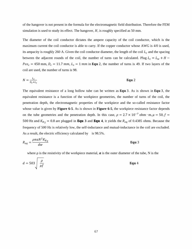
67
of the hangover is not present in the formula for the electromagnetic field distribution. Therefore the FEM
simulation is used to study its effect. The hangover, 𝐻, is roughly specified as 50 mm.
The diameter of the coil conductor dictates the ampere capacity of the coil conductor, which is the
maximum current the coil conductor is able to carry. If the copper conductor whose AWG is 4/0 is used,
its ampacity is roughly 260 A. Given the coil conductor diameter, the length of the coil 𝐿𝑐 and the spacing
between the adjacent rounds of the coil, the number of turns can be calculated. Plug 𝐿𝑐 = 𝐿𝑤 + 𝐻 −
𝑃𝑜𝑠𝑐 = 450 mm, 𝐷𝑐 = 11.7 𝑚𝑚, 𝐿𝑠 = 1 𝑚𝑚 in 𝐄𝐪𝐮 2, the number of turns is 49. If two layers of the
coil are used, the number of turns is 98.
𝑁 =𝐿𝑐
𝐷𝑐+𝐿𝑠 𝐄𝐪𝐮 2
The equivalent resistance of a long hollow tube can be written as 𝐄𝐪𝐮 3. As is shown in 𝐄𝐪𝐮 3, the
equivalent resistance is a function of the workpiece geometries, the number of turns of the coil, the
penetration depth, the electromagnetic properties of the workpiece and the so-called resistance factor
whose value is given by Figure 6-5. As is shown in Figure 6-5, the workpiece resistance factor depends
on the tube geometries and the penetration depth. In this case, 𝜌 = 2.7 × 10⁻⁷ ohm ∙ m, 𝜇 = 50, 𝑓 =
500 Hz and 𝐾𝑅2 = 0.8 are plugged in 𝐄𝐪𝐮 3 and 𝐄𝐪𝐮 4, it yields the 𝑅𝑒𝑞 of 0.4385 ohms. Because the
frequency of 500 Hz is relatively low, the self-inductance and mutual-inductance in the coil are excluded.
As a result, the electric efficiency calculated by is 98.5%.
𝑅𝑒𝑞 =𝜌𝜋𝑎𝑁2𝐾𝑅2
𝑑𝑤 𝐄𝐪𝐮 3
where ρ is the resistivity of the workpiece material, 𝒂 is the outer diameter of the tube, N is the
𝑑 = 503√ 𝜌
𝜇𝑓 𝐄𝐪𝐮 4
68
Figure 6-5. Workpiece Resistance Factor 𝐊𝐑𝟐 [12]
The ideal heat, 𝑃𝑤, is used to raise the temperature of a certain mass of material. Therefore its calculation
is given by 𝐄𝐪𝐮 5. Plug 𝑚 = 4.7 kg, 𝑇𝑓 = 11000 C o , 𝑇𝑖𝑛 = 20 C
o , 𝑐 = 473 J/(kg ∙ K) and 𝑡 =
120 seconds in 𝐄𝐪𝐮 5, 𝑃𝑤 is 40121 W. In the industrial application, the production rate is evaluated by
the mass per unit time. In this case, the production rate is 0.14 ton/hr. Calculation of the power loss due to
radiation and convection is given by 𝐄𝐪𝐮 6 and 𝐄𝐪𝐮 7 respectively. Due to presence of heat loss caused
by radiation and convention, the total heat input to the workpiece is the sum of the ideal heat and the heat
loss. It turns out that 𝑃𝑡𝑜𝑡𝑎𝑙 is 40753 W.
𝑃𝑤 =𝑚 ∫ 𝑐(𝑇)𝑑𝑇
𝑇𝑓
𝑇𝑖𝑛
𝑡≈
𝑚𝑐(𝑇𝑓 − 𝑇𝑖𝑛)
𝑡 𝐄𝐪𝐮 5
where m is the mass for heating, c is the specific heat, 𝑇𝑓 is the final temperature, 𝑇𝑖𝑛 is the initial
temperature and t is the heating time.
𝑄𝑐𝑜𝑛𝑣 = 1.86(𝑇𝑠 − 𝑇𝑎)1.3𝑆 𝐄𝐪𝐮 6
where 𝑇𝑠 is the surface temperature, 𝑇𝑎 is the ambient temperature, S is the contact surface area.
𝑄𝑟𝑎𝑑 = 5.67 × 10⁻⁸𝜀[(𝑇𝑠 + 273)4 + (𝑇𝑎 + 273)4]𝑆 𝐄𝐪𝐮 7
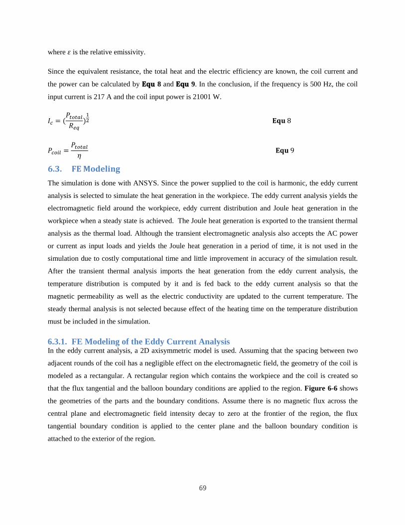
69
where 𝜀 is the relative emissivity.
Since the equivalent resistance, the total heat and the electric efficiency are known, the coil current and
the power can be calculated by 𝐄𝐪𝐮 8 and 𝐄𝐪𝐮 9. In the conclusion, if the frequency is 500 Hz, the coil
input current is 217 A and the coil input power is 21001 W.
𝐼𝑐 = (𝑃𝑡𝑜𝑡𝑎𝑙
𝑅𝑒𝑞)
12 𝐄𝐪𝐮 8
𝑃𝑐𝑜𝑖𝑙 =𝑃𝑡𝑜𝑡𝑎𝑙
𝜂 𝐄𝐪𝐮 9
6.3. FE Modeling
The simulation is done with ANSYS. Since the power supplied to the coil is harmonic, the eddy current
analysis is selected to simulate the heat generation in the workpiece. The eddy current analysis yields the
electromagnetic field around the workpiece, eddy current distribution and Joule heat generation in the
workpiece when a steady state is achieved. The Joule heat generation is exported to the transient thermal
analysis as the thermal load. Although the transient electromagnetic analysis also accepts the AC power
or current as input loads and yields the Joule heat generation in a period of time, it is not used in the
simulation due to costly computational time and little improvement in accuracy of the simulation result.
After the transient thermal analysis imports the heat generation from the eddy current analysis, the
temperature distribution is computed by it and is fed back to the eddy current analysis so that the
magnetic permeability as well as the electric conductivity are updated to the current temperature. The
steady thermal analysis is not selected because effect of the heating time on the temperature distribution
must be included in the simulation.
6.3.1. FE Modeling of the Eddy Current Analysis In the eddy current analysis, a 2D axisymmetric model is used. Assuming that the spacing between two
adjacent rounds of the coil has a negligible effect on the electromagnetic field, the geometry of the coil is
modeled as a rectangular. A rectangular region which contains the workpiece and the coil is created so
that the flux tangential and the balloon boundary conditions are applied to the region. Figure 6-6 shows
the geometries of the parts and the boundary conditions. Assume there is no magnetic flux across the
central plane and electromagnetic field intensity decay to zero at the frontier of the region, the flux
tangential boundary condition is applied to the center plane and the balloon boundary condition is
attached to the exterior of the region.
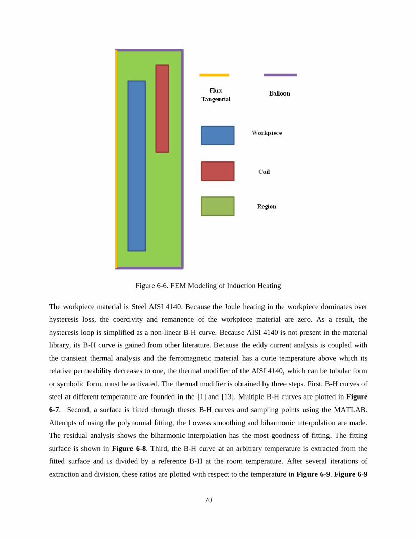
70
Figure 6-6. FEM Modeling of Induction Heating
The workpiece material is Steel AISI 4140. Because the Joule heating in the workpiece dominates over
hysteresis loss, the coercivity and remanence of the workpiece material are zero. As a result, the
hysteresis loop is simplified as a non-linear B-H curve. Because AISI 4140 is not present in the material
library, its B-H curve is gained from other literature. Because the eddy current analysis is coupled with
the transient thermal analysis and the ferromagnetic material has a curie temperature above which its
relative permeability decreases to one, the thermal modifier of the AISI 4140, which can be tubular form
or symbolic form, must be activated. The thermal modifier is obtained by three steps. First, B-H curves of
steel at different temperature are founded in the [1] and [13]. Multiple B-H curves are plotted in Figure
6-7. Second, a surface is fitted through theses B-H curves and sampling points using the MATLAB.
Attempts of using the polynomial fitting, the Lowess smoothing and biharmonic interpolation are made.
The residual analysis shows the biharmonic interpolation has the most goodness of fitting. The fitting
surface is shown in Figure 6-8. Third, the B-H curve at an arbitrary temperature is extracted from the
fitted surface and is divided by a reference B-H at the room temperature. After several iterations of
extraction and division, these ratios are plotted with respect to the temperature in Figure 6-9. Figure 6-9
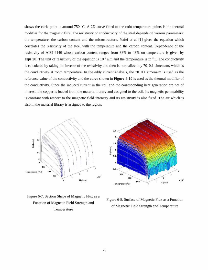
71
shows the curie point is around 750 oC. A 2D curve fitted to the ratio-temperature points is the thermal
modifier for the magnetic flux. The resistivity or conductivity of the steel depends on various parameters:
the temperature, the carbon content and the microstructure. Yafei et al [1] gives the equation which
correlates the resistivity of the steel with the temperature and the carbon content. Dependence of the
resistivity of AISI 4140 whose carbon content ranges from 38% to 43% on temperature is given by
𝐄𝐪𝐮 10. The unit of resistivity of the equation is 10-6 Ωm and the temperature is in
oC. The conductivity
is calculated by taking the inverse of the resistivity and then is normalized by 7010.1 simens/m, which is
the conductivity at room temperature. In the eddy current analysis, the 7010.1 simens/m is used as the
reference value of the conductivity and the curve shown in Figure 6-10 is used as the thermal modifier of
the conductivity. Since the induced current in the coil and the corresponding heat generation are not of
interest, the copper is loaded from the material library and assigned to the coil. Its magnetic permeability
is constant with respect to the magnetic field intensity and its resistivity is also fixed. The air which is
also in the material library is assigned to the region.
Figure 6-7. Section Shape of Magnetic Flux as a
Function of Magnetic Field Strength and
Temperature
Figure 6-8. Surface of Magnetic Flux as a Function
of Magnetic Field Strength and Temperature
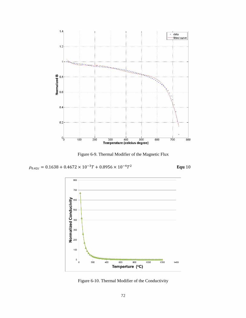
72
Figure 6-9. Thermal Modifier of the Magnetic Flux
𝜌0.42𝑐 = 0.1638 + 0.4672 × 10⁻³𝑇 + 0.8956 × 10⁻⁴𝑇2 𝐄𝐪𝐮 10
Figure 6-10. Thermal Modifier of the Conductivity
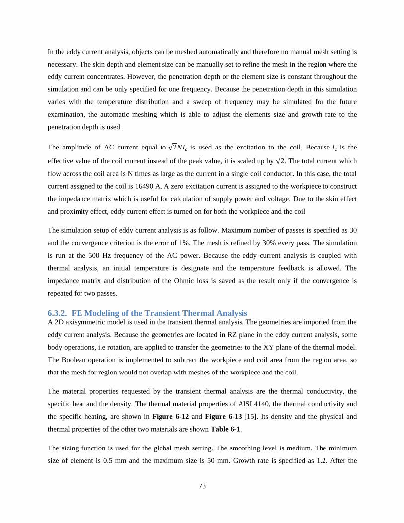
73
In the eddy current analysis, objects can be meshed automatically and therefore no manual mesh setting is
necessary. The skin depth and element size can be manually set to refine the mesh in the region where the
eddy current concentrates. However, the penetration depth or the element size is constant throughout the
simulation and can be only specified for one frequency. Because the penetration depth in this simulation
varies with the temperature distribution and a sweep of frequency may be simulated for the future
examination, the automatic meshing which is able to adjust the elements size and growth rate to the
penetration depth is used.
The amplitude of AC current equal to √2𝑁𝐼𝑐 is used as the excitation to the coil. Because 𝐼𝑐 is the
effective value of the coil current instead of the peak value, it is scaled up by √2. The total current which
flow across the coil area is N times as large as the current in a single coil conductor. In this case, the total
current assigned to the coil is 16490 A. A zero excitation current is assigned to the workpiece to construct
the impedance matrix which is useful for calculation of supply power and voltage. Due to the skin effect
and proximity effect, eddy current effect is turned on for both the workpiece and the coil
The simulation setup of eddy current analysis is as follow. Maximum number of passes is specified as 30
and the convergence criterion is the error of 1%. The mesh is refined by 30% every pass. The simulation
is run at the 500 Hz frequency of the AC power. Because the eddy current analysis is coupled with
thermal analysis, an initial temperature is designate and the temperature feedback is allowed. The
impedance matrix and distribution of the Ohmic loss is saved as the result only if the convergence is
repeated for two passes.
6.3.2. FE Modeling of the Transient Thermal Analysis A 2D axisymmetric model is used in the transient thermal analysis. The geometries are imported from the
eddy current analysis. Because the geometries are located in RZ plane in the eddy current analysis, some
body operations, i.e rotation, are applied to transfer the geometries to the XY plane of the thermal model.
The Boolean operation is implemented to subtract the workpiece and coil area from the region area, so
that the mesh for region would not overlap with meshes of the workpiece and the coil.
The material properties requested by the transient thermal analysis are the thermal conductivity, the
specific heat and the density. The thermal material properties of AISI 4140, the thermal conductivity and
the specific heating, are shown in Figure 6-12 and Figure 6-13 [15]. Its density and the physical and
thermal properties of the other two materials are shown Table 6-1.
The sizing function is used for the global mesh setting. The smoothing level is medium. The minimum
size of element is 0.5 mm and the maximum size is 50 mm. Growth rate is specified as 1.2. After the
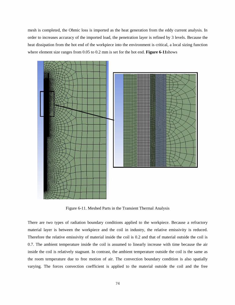
74
mesh is completed, the Ohmic loss is imported as the heat generation from the eddy current analysis. In
order to increases accuracy of the imported load, the penetration layer is refined by 3 levels. Because the
heat dissipation from the hot end of the workpiece into the environment is critical, a local sizing function
where element size ranges from 0.05 to 0.2 mm is set for the hot end. Figure 6-11shows
Figure 6-11. Meshed Parts in the Transient Thermal Analysis
There are two types of radiation boundary conditions applied to the workpiece. Because a refractory
material layer is between the workpiece and the coil in industry, the relative emissivity is reduced.
Therefore the relative emissivity of material inside the coil is 0.2 and that of material outside the coil is
0.7. The ambient temperature inside the coil is assumed to linearly increase with time because the air
inside the coil is relatively stagnant. In contrast, the ambient temperature outside the coil is the same as
the room temperature due to free motion of air. The convection boundary condition is also spatially
varying. The forces convection coefficient is applied to the material outside the coil and the free
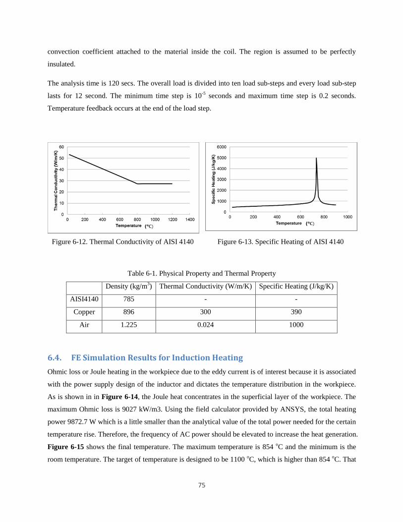
75
convection coefficient attached to the material inside the coil. The region is assumed to be perfectly
insulated.
The analysis time is 120 secs. The overall load is divided into ten load sub-steps and every load sub-step
lasts for 12 second. The minimum time step is 10-5
seconds and maximum time step is 0.2 seconds.
Temperature feedback occurs at the end of the load step.
Figure 6-12. Thermal Conductivity of AISI 4140 Figure 6-13. Specific Heating of AISI 4140
Table 6-1. Physical Property and Thermal Property
Density (kg/m3) Thermal Conductivity (W/m/K) Specific Heating (J/kg/K)
AISI4140 785 - -
Copper 896 300 390
Air 1.225 0.024 1000
6.4. FE Simulation Results for Induction Heating
Ohmic loss or Joule heating in the workpiece due to the eddy current is of interest because it is associated
with the power supply design of the inductor and dictates the temperature distribution in the workpiece.
As is shown in in Figure 6-14, the Joule heat concentrates in the superficial layer of the workpiece. The
maximum Ohmic loss is 9027 kW/m3. Using the field calculator provided by ANSYS, the total heating
power 9872.7 W which is a little smaller than the analytical value of the total power needed for the certain
temperature rise. Therefore, the frequency of AC power should be elevated to increase the heat generation.
Figure 6-15 shows the final temperature. The maximum temperature is 854 oC and the minimum is the
room temperature. The target of temperature is designed to be 1100 oC, which is higher than 854
oC. That
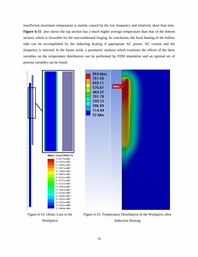
76
insufficient maximum temperature is mainly caused by the low frequency and relatively short heat time.
Figure 6-15 also shows the top section has a much higher average temperature than that of the bottom
section, which is favorable for the non-isothermal forging. In conclusion, the local heating of the hollow
tube can be accomplished by the inducting heating if appropriate AC power, AC current and the
frequency is selected. In the future work, a parametric analysis which examines the effects of the three
variables on the temperature distribution can be performed by FEM simulation and an optimal set of
process variables can be found.
Figure 6-14. Ohmic Loss in the
Workpiece
Figure 6-15. Temperature Distribution of the Workpiece after
Induction Heating
77
Chapter 7
Concluding Remarks
A differential heating-based forming which is also referred to as the non-isothermal forging presents the
opportunity of creating a pseudo die, the part of the billet material that would act as a die or punch to
transmit the forming load to the desired regions. This methodology offers new possibilities for designing
high-power-density hollow shafts. Although managing differential heating poses a challenge, most
forging companies use similar technologies for billet heating or heat treatment on specific locations of
forged parts.
This proposed methodology was introduced for the first time in the Light Weight Forging project where
the feasibility of the process for forging hollow shafts from tubular billets was examined based on the
formability and forming load. FE simulations carried out for hollow axle shafts, gear box main shafts, and
hollow pinion gear shafts show i) the maximum strain of the final part approaches the upper limit of hot
forging formability and a concentrated strain band occurs at the center of the flange or the bevel head,
which will be addressed by improving the metal flow pattern and the heating scheme, ii) the press
capacity needed by the process is common in the industry. In this report we have extended the analysis
by considering various factors that are important for producing reliable high-power-density shaft as well
as exploring other geometries that may be good candidates for this process. The factors that have been
considered in the current study include (a) how to increase uniformity of wall thickness along the axis of
the shaft, (b) how to reduce cost and die fabrication issues caused by excessively long dies, (c) how to
prevent localized wall thickening, particularly, when forging main shaft for gear boxes, (d) how to
achieve large flange sizes for relatively thin walled hollow main shaft, as the flange size is a function of
ID/OD ratio of the tubular billet, and (e) the feasibility of producing complex features such as steps or
concave shapes on the shaft.
These aspects have been investigated in this report and the findings are summarized below. It should also
be noted that, some of the ideas may not be cost effective, but it was deemed necessary to include at this
stage.
To control wall thickness the possibility of adding an ironing stage have been studied. This could
be carried out using a mandrel or a punch. The simulation results showed that the wall tolerance at the
center hole can be reduced to as low as 0.05mm.
78
Excessively long dies used in the upsetting stage could be reduced by dividing the die set into two.
Most of the cold material will not be supported (part of the billet becomes pseudo die). The dies should,
however, be carefully designed to ensure that upsetting loads do not surpass the strength the pseudo dies.
More complex hollow shaft geometries such as double flanged main shaft or axles could be
produced by combining radial forging and non-isothermal forging. Introduction of radial forging may
increase the complexity of the process, particularly, if the number of radial dies to be used is high.
However, if only two dies (bottom and top) are used, the forging operation will be similar to conventional
forging operations.
Premature folding usually occur during upsetting (main shaft forging). The simulations have
demonstrated that by attaching a mandrel to the top die, premature folding and wall thickening problems
can easily be prevented.
A laboratory tooling to validate the proposed concept is expected to be fabricated at NCSU.
Aluminum material will be used. The FE simulations results have shown that when non-isothermal
forging is applied to aluminum workpieces, the transitional region which connects the solid section and
the hollow section is extended. In other words, forging of aluminum hollow shafts using the proposed
technique will be more challenging than using steel materials.
Preliminary analysis on induction heating was carried to estimate process parameters. More
refinement in the simulations will be carried out later. The preliminary analysis and simulations have
shown that the workpiece (tube sizes used in this report) can be locally heated to a desired temperature
within 120 seconds using a two layered coil of 98 turns.
79
Reference [1] Workshop report on Trucks and Heavy-Duty Vehicles Technical Requirements and Gaps for
Lightweight and Propulsion Materials,
http://energy.gov/sites/prod/files/2014/03/f13/wr_trucks_hdvehicles.pdf
[2] http://www.nytimes.com/2014/02/19/us/politics/obama-to-request-new-rules-for-cutting-truck-
pollution.html
[3] K. Dalaei, B. Karlsson, Influence of shot peening on fatigue durability of normalized steel subjected
to variable amplitude loading, Int J Fatigue, 38 (2012), pp. 75–83
[4] M.A.S. Torres, H.J.C. Voorwald, An evaluation of shot peening, residual stress and stress relaxation
on the fatigue life of AISI 4340 steel, Int J Fatigue, 24 (2002), pp. 877–886
[5] H. Gangaraj SM, Moridi, A, Guagliano, M. Ghidini, A. Boniardi, M. The effect of nitriding, severe
shot peening and their combination on the fatigue behavior and micro-structure of a low-alloy steel.
Int J Fatigue 2013),http://dx.doi.org/10.1016/j.ijfatigue.2013.04.017
[6] K. Oguri, Fatigue life enhancement of aluminum alloy for aircraft by Fine Particle Shot Peening
(FPSP) Journal of Materials Processing Technology, V. 211, (2011), pp. 1395-1399
[7] S. Huang, J.Z. Zhou, J. Sheng, K.Y. Luo, J.Z. Lu, Z.C. Xu, X.K. Meng, L. Dai, L.D. Zuo, H.Y. Ruan,
H.S. Chen, Effects of laser peening with different coverage areas on fatigue crack growth properties
of 6061-T6 aluminum alloy International Journal of Fatigue, V 47, (2013), pp 292-299
[8] Y. Harada, K. Fukaura, S. Haga, Influence of microshot peening on surface layer characteristics of
structural steel, J Mater Process Technol, 191 (2007), pp. 297–301
[9] X.C. Zhang, Y.K. Zhang, J.Z. Lu, F.Z. Xuan, Z.D. Wang, S.T. Tu, Improvement of fatigue life of Ti-
6Al-4V alloy by laser shock peening, Mater Sci Eng A, 527 (2010), pp. 3411–3415
[10] Hao Pang. Gracious Ngaile, Process Development of Hollow and Bimetallic Power Transmission
Shafts. Phase III Progress Report No. F/MAE/NG/-2016-04, 2016
[11] Rudnev, Valery, et al. Handbook of induction heating. CRC Press, 2002.
[12] Semiatin, S. L. Elements of induction heating: design, control, and applications. ASM International,
1988.
[13] http://www.fieldp.com/magneticproperties.html#Steel1018
[14] Yafei, Sun, Niu Dongjie, and Sun Jing. "Temperature and carbon content dependence of electrical
resistivity of carbon steel." 2009 4th IEEE Conference on Industrial Electronics and Applications.
IEEE, 2009.
[15] http://www.mace.manchester.ac.uk/project/research/structures/strucfire/materialInFire/Steel/HotRoll
edCarbonSteel/thermalProperties.htm