development of a monocular vision platform and algorithm ... · development of a monocular vision...
TRANSCRIPT

Development of a Monocular Vision Platform andAlgorithm for Navigation in Confined Underwater
Space
Ali AlSaibieGeorgia Institute of Technology
under the direction ofProf. Kamal Youcef-Toumi
Mechatronics Research LaboratoryMechanical Engineering Department
Massachusetts Institute of Technology
Summer Research InternshipJune 2, 2014 — August 22, 2014
Kuwait-MIT Center for Natural Resources and the EnvironmentAugust 22, 2014
CONTENTS
I Abstract 2
II Introduction 3
III Maneuverable Robot for In-Pipe Leak Detection 3
IV The Vision Problem: Pose Estimation and Obstacle Detection 3IV-A Projected-Ellipse Based Pose Estimation . . . . . . . . . . . . . . . . . . . . . . . . 3IV-B Obstacle, Bend, and Junction Detection . . . . . . . . . . . . . . . . . . . . . . . . 4
V Development of Hardware & Software Platform 5V-A On-Board Vision Processing . . . . . . . . . . . . . . . . . . . . . . . . . . . . . . 5V-B Experimentation with a TTL Camera . . . . . . . . . . . . . . . . . . . . . . . . . . 6V-C Use of a IP-Camera . . . . . . . . . . . . . . . . . . . . . . . . . . . . . . . . . . . 6V-D Camera Modular Attachment Design . . . . . . . . . . . . . . . . . . . . . . . . . . 7V-E On-board Electronics . . . . . . . . . . . . . . . . . . . . . . . . . . . . . . . . . . 7V-F PC-Based Control Center . . . . . . . . . . . . . . . . . . . . . . . . . . . . . . . . 8
VI Conclusion and Future Work 8
VII Acknowledgments 8
References 9
Appendix A: LED Layout 10
Appendix B: Eagle Schematic 11
1

I. ABSTRACT
The Mechatronics Research Laboratory at MIT is developing a maneuverable swimming in-pipe inspec-tion robot that is capable of performing complicated movements and sharp turns. Assuming full 6-DOFcontrollability, the robot requires knowledge of its position with reference to the pipe wall in order toboth center itself with respect to the pipe circumference and to be able to distinguish bends in order tonavigate through them. This project will seek to develop a monocular vision platform and derive imageprocessing algorithms to achieve those objectives.
2

II. INTRODUCTION
Leaks in infrastructure and transportation pipelines are a growing concern around the world. With thedrive toward maintaining higher levels of safety concurrent with the need to run an efficient and profitablebusiness, pipeline operators are under constant pressure to develop effective and efficient inspection andleak detection technologies on the ever-aging and expanding pipelines infrastructures. Over the past decade,there has a been a major improvement in the ability to inspect pipelines, as a result of the improvementin the inspection technologies developed that target a wider range of pipeline structures as well as to themodifications being made by the pipeline operators to their piping system that have allowed the use ofthe existing inspection technologies [1]. However, there still remains a significant percentage of pipelinesystems that present a challenge to the existing inspection technologies. The current limitations can becharacterized in brief by the following three areas:
• Size: Where a small or variable-diameter pipe imposes a challenge.• Bends, Connections and Restrictions: Where a limited maneuverability inspection tool cannot be
used.• Flow and Access: Where the flow rate of the fluid is outside the bound of operability of the inspection
tool or where the inspection tool cannot be loaded onto or retrieved from the pipe.
To overcome some of these limitations, the Mechatronics Research Laboratory (MRL) at MIT havebeen developing self-propelled in-pipe inspection robots and one of those is a maneuverable swimmingrobot that is able to “swim” in utility water pipes. However, to be able to navigate the water pipe networkthe robot requires an on-board sensory system that allows it to navigate in pipes.
This report summarizes the work performed during the internship in developing a monocular visionbased platform and associated algorithms as an addition to the existing swimming robot platform. Thereport will review the initial sensory model and the work performed in developing the auxiliary visionmechatronic system. Future work required to complete the theoretical framework will be discussed.
III. MANEUVERABLE ROBOT FOR IN-PIPE LEAK DETECTION
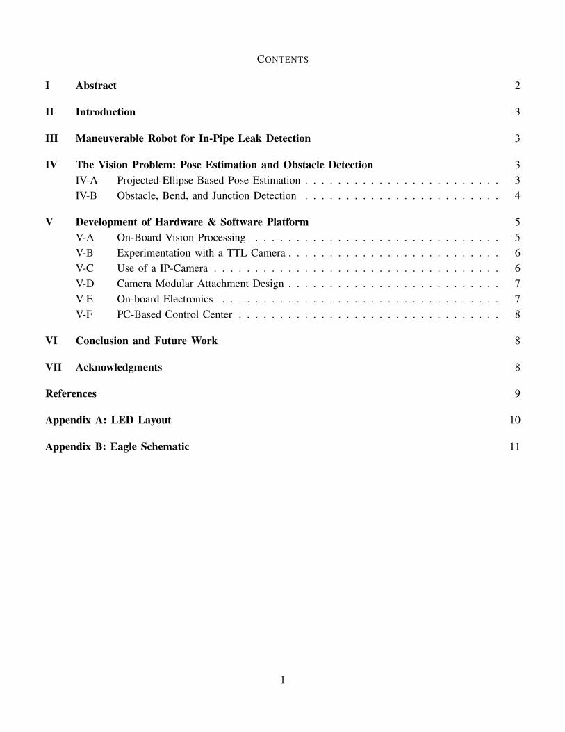
The robot developed at MRL shown in Figure 1 is intended to be self buoyant and be able to swimthe 4-inch pipe using on-board thrusters. The maneuverable robot features a shell shaped to minimize thedrag and house compact brushless motors designed and built at the MRL. [3]
IV. THE VISION PROBLEM: POSE ESTIMATION AND OBSTACLE DETECTION
The first part of the sensory problem is concerned with estimating the position and orientation of therobot with respect to the pipe’s cross section. This is in order to allow the robot to maintain it’s headingand centricity. The other part of the sensory problem is concerned with detecting obstacles, bends andjunctions in the pipe in order to navigate through them.
A. Projected-Ellipse Based Pose Estimation
The proposed method for estimating the pose of the robot in pipe is by using Light Emitting Diodes(LEDs) that project light onto the internal wall of the pipe. A reflection in the form of ellipses areformed on the wall which are captured by a single cameras sensor. The LEDs would be oriented in a
3
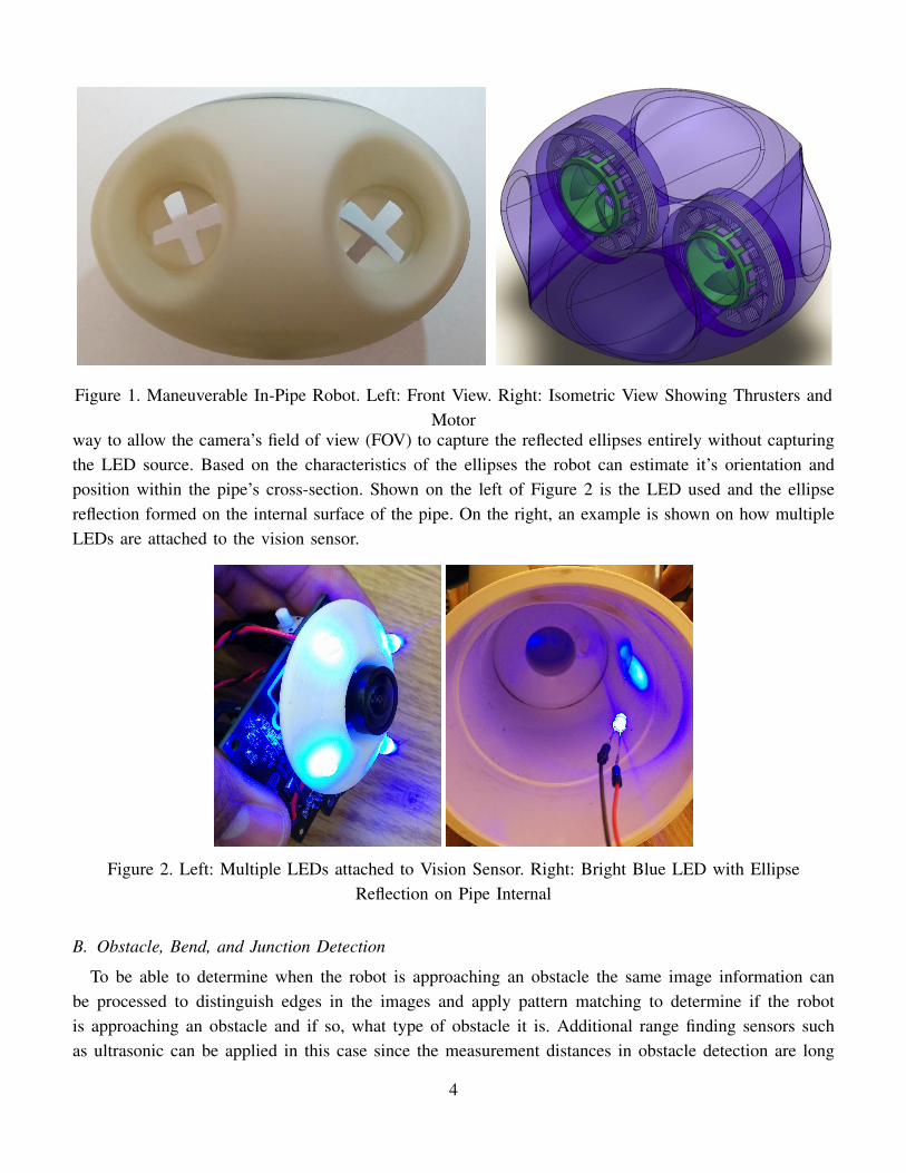
Figure 1. Maneuverable In-Pipe Robot. Left: Front View. Right: Isometric View Showing Thrusters andMotor
way to allow the camera’s field of view (FOV) to capture the reflected ellipses entirely without capturingthe LED source. Based on the characteristics of the ellipses the robot can estimate it’s orientation andposition within the pipe’s cross-section. Shown on the left of Figure 2 is the LED used and the ellipsereflection formed on the internal surface of the pipe. On the right, an example is shown on how multipleLEDs are attached to the vision sensor.
Figure 2. Left: Multiple LEDs attached to Vision Sensor. Right: Bright Blue LED with EllipseReflection on Pipe Internal
B. Obstacle, Bend, and Junction Detection
To be able to determine when the robot is approaching an obstacle the same image information canbe processed to distinguish edges in the images and apply pattern matching to determine if the robotis approaching an obstacle and if so, what type of obstacle it is. Additional range finding sensors suchas ultrasonic can be applied in this case since the measurement distances in obstacle detection are long
4

enough to apply currently available ultrasonic sensors.
V. DEVELOPMENT OF HARDWARE & SOFTWARE PLATFORM
In order to deploy an image sensory system it was necessary to develop a vision system hardware andsoftware platform that can be added to the existing robot and meet it’s power and, more importantly, smallsize requirements.
A. On-Board Vision Processing
Initial experimental work was performed on an open-source camera module with on-board processingcapabilities called PixyMon (CMU5). The camera was modified with a fish-eye view lens, increasing itsFOV from 75deg to 145deg. In addition to the lens, a blue light band-pass filter with a wavelength of467nm and a narrow bandwidth of 10nm matching that of the blue LED wavelength range was added.Water strongly absorbs light waves and the choice of blue light was because of it being the least absorbedvisible light color in water as can be seen from Figure 3. Figure 4 shows, at the right, a captured imagewithin the 4inch pipe showing the LED reflections in the horizontal plane of the camera. The image onthe left shows the ellipses found after processing. The image frames were processed on the PC side usingOpenCV. The following image processing steps were performed.
1) Image Binarization2) Image Blur3) Contour Detection and Mapping
Figure 3. Absorption Strength of Electromagnetic Waves in Water. Retrieved [2]
The intention of this project was to modify the open-source camera hardware by reducing its PCB sizeto fit in the robot as a first option, this would have allowed the possibility of on-board image processingto be performed; however, after starting to redesign the board it was realized that in the interest of time onthe internship, a faster method to adapt a camera on the robot is needed. An on-board vision processingmodule would ultimately be required to fully exploit the benefit of the maneuverable robot.
5

Figure 4. Right: Ellipse Projection as Captured with Camera with Lens Filter. Left: Ellipse ContourDetection Applied
B. Experimentation with a TTL Camera
In an effort to use a smaller sized camera on board the robot, attempts were made to use the TTLcamera shown in Figure 5 as a second option. The idea was to relay the compressed jpeg image frame datathrough the robot’s serial wireless communication to the PC where it will be decompressed and processed.The camera’s speed is limited by the baud rate of the serial communication between the camera’s DSPand the robot’s micro-controller. With reducing the camera’s resolution to the lowest size of 120x80 andemploying a multi-threaded algorithm on the robot to receive and send image data concurrently, the bestattained image frame transfer rate per second was about 1 frames per second which is very slow for thisapplication unfortunately.
Figure 5. TTL Camera Module
C. Use of a IP-Camera
A third option found was a to use a mini-sized WiFi camera (Ai-Ball IP/WiFi Camera). The camera cancommunicate directly with the PC at 30 fps. The only limitation is that WiFi signal is heavily weakenedunderwater. But for the purposes of experimentation an antenna coil can be added around the testing pipesegment.
6

D. Camera Modular Attachment Design
To attach the WiFi Camera to the robot, a modular attachment was designed that can be interchanged.A render and an actual image of the camera attachment are shown in Figure 6. The Module houses thecamera lens, the LEDs and the camera electronics. Appendix A shows how the LEDs are placed to obtainvisibility of the ellipse reflection within a 4inch pipe.
Figure 6. Camera Attachment Module
E. On-board Electronics
In addition to developing a vision platform, and given the space limitation inside the robot, a com-pact robot printed circuit board (PCB) shown in Figure was designed to allow the addition of reversefunctionality Electronics Speed Controllers (ESC). The board also included a 9DOF IMU, a barometricpressure sensor and MOSFET drivers to control power supply to the LEDs and the attached camerathrough software. A schematic of the designed PCB is attached in appendix B.
Figure 7. 4 Layer Printer Circuit Board attached to Teensy Microcontroller
7

F. PC-Based Control Center
To be able to capture the video data through WiFi, communicate with the robot through a wireless XBeeserial interface and to be able to manually navigate the robot, a PC-based control system was developedusing Qt C++ framework.
Figure 8 shows the software architecture as applied across the PC and Robot. The vision processingis performed solely on the PC side; however, the supervisory control can be placed at either the PCor Robot side. For now and for easier debugging purposes, the supervisory controller and associatednavigation algorithms are kept on the PC side.
Telemetry Driver
Joystick Driver
Processes Scheduler
Vision Driver
Vision Processor
GUI
User Interface Controller
Navigator – Supervisory Control
Telemetry Driver
On-Board CameraJoystick
IMU Processor
IMU Driver
Motor Driver
MOSFET Driver
Swimming Robot
Serial RF
USB
WiFI
LED Array
Motors
Figure 8. Software Architecture
VI. CONCLUSION AND FUTURE WORK
Developing a maneuverable swimming robot in confined spaces is a novel concept and one of its mainchallenges is the ability to smoothly navigate within these confined spaces. This work began to explore theuse of vision sensors to allow a swimming robot to navigate in a pipe by developing an initial computervision framework in parallel with developing the hardware and software platform for the vision system. Inorder to achieve the goal of the project the pose estimation and obstacle detection algorithms’ developmentmust be completed. The vision system platform also requires minor enhancement and tweaking both onthe hardware and software side in order to implement the computer vision capabilities. This additionalwork is planned to be carried forward after the internship as part of further graduate studies.
VII. ACKNOWLEDGMENTS
I would like to thank Professor Kamal Youcef-Toumi and his team at the Mechatronics Research Labat MIT for hosting me during this summer. I would like to specifically thank You Wu for his continuedassistance throughout my work here.
I would also like to thank the Kuwait-MIT Center for Natural Resources and the Environment for theallowing me to take part in this valuable summer research experience and thank Dr. Murad Abu-Khalafand Laura Guild for their assistance and hospitality.
8

REFERENCES
[1] J. Tiratsoo. (2013) The ultimate guide to unpiggable pipelines.[2] M. Chaplin. (2014) Water absorption spectrum. [Online]. Available: http://www1.lsbu.ac.uk/water/vibrat.html[3] Y. Wu, “Design and fabrication of a maneuverable robot for in-pipe leak detection,” Master’s thesis, MASSACHUSETTS INSTITUTE
OF TECHNOLOGY, jun 2014.[4] S. Ma, “Conics-based stereo, motion estimation, and pose determination,” International Journal of Computer Vision, vol. 10, no. 1,
pp. 7–25, Feb. 1993. [Online]. Available: http://link.springer.com/10.1007/BF01440844[5] Q. Ji, “Face Pose Estimation From a Face Ellipse,” pp. 1–4.[6] J. Usabiaga, A. Erol, G. Bebis, R. Boyle, and X. Twombly, “Global hand pose estimation by multiple camera ellipse tracking,” Machine
Vision and Applications, vol. 21, no. 1, pp. 1–15, May 2008. [Online]. Available: http://link.springer.com/10.1007/s00138-008-0137-z[7] M. Hutter, N. Brewer, R. Anu, and S. M. L. Nicta, “Matching 2-D Ellipses to 3-D Circles with Application to Vehicle Pose Identification,”
pp. 1–16, 2009.[8] F. Bruno, G. Bianco, M. Muzzupappa, S. Barone, and a.V. Razionale, “Experimentation of structured light and stereo vision for
underwater 3D reconstruction,” ISPRS Journal of Photogrammetry and Remote Sensing, vol. 66, no. 4, pp. 508–518, Jul. 2011.[Online]. Available: http://linkinghub.elsevier.com/retrieve/pii/S0924271611000414
[9] E. Trucco and A. Verri, Introductory techniques for 3-D computer vision / Emanuele Trucco, Alessandro Verri. Upper Saddle River,NJ : Prentice Hall, c1998., 1998.
[10] G. Panin, Model-based visual tracking : the OpenTL framework / Giorgio Panin. Hoboken, N.J. : Wiley, c2011., 2011.[11] D. Forsyth and J. Ponce, Computer vision : a modern approach / David A. Forsyth, Jean Ponce. Boston : Pearson, 2012., 2012.[12] T. Liu, L. Wan, and X. W. Liang, “A Monocular Vision Measurement Algorithm Based on the Underwater Robot,” Applied Mechanics
and Materials, vol. 532, pp. 165–169, Feb. 2014. [Online]. Available: http://www.scientific.net/AMM.532.165[13] M. Faessler, E. Mueggler, K. Schwabe, and D. Scaramuzza, “A Monocular Pose Estimation System based on Infrared LEDs.”
9

AP
PE
ND
IXA
LE
DL
AY
OU
T
2
15
6
20°
37.
50°
37.
50°
100
2
12
5
15°
32°
3
2°
100
Horiz
onta
l Lay
out
Ver
tical
Lay
out
Solid
Wor
ks S
tude
nt E
ditio
n. F
or A
cade
mic
Use
Onl
y.
10

AP
PE
ND
IXB
EA
GL
ES
CH
EM
AT
IC
Pow
er &
Dri
vers
10D
OF
IMU
Te
en
sy M
CU
Du
al E
SCs
11