development of a novel rheometric device for the ...doras.dcu.ie/18297/1/salma_akhter.pdf · b...
TRANSCRIPT

Development of a Novel Rheometric Device for the Determination of Pressure Dependent
Viscosity of non-Newtonian Fluids
b y
Salma Akhter, B.Sc. Eng.
M.Eng. 2000

Development of a Novel Rheometric Device for the Determination of Pressure Dependent
Viscosity of non-Newtonian Fluids
by
Salma Akhter, B.Sc. Eng.
This thesis is submitted to Dublin City University as the fulfilment of the requirement for the award of the degree of
Master of Engineering
Supervisor1 Professor M.S.J. Hashmi, Ph.D, D.Sc.
School of Mechanical and Manufacturing Engineering Dublin City University
F e b ru a ry , 2000

I
DECLARATION
I hereby certify that this material, which I now submit for assessment on the
programme of study leading to the award of Master o f Engineering, is entirely my
own work and has not been taken from the work of others save and to the extent
that such work has been cited and acknowledged within the text of my work
Singed S ID N o 9697!509
Salma Akhter
Date February 2000

)
Dedication
This thesis is ded ica ted to my paren ts who took a ll the troubles in the w orld with sm ile fo r the advancem ent o f their children's knowledge and to my husband and daughter

Acknowledgements
I would like to express my sincere thanks and gratitude to Prof M S J Hashmi
my supervisor and Head of School of Mechanical and Manufacturing Engineering of
Dublin City University for his kind supervision, guidance, encouragement and advice
throughout the course of this work The author would like to thank Professor Hashmi
for offering the opportunity to do research work at the School of Mechanical and
Manufacturing Engineering School, Dublin City University
Special thanks to Mr Liam Domican and Mr Michael Tyrell for their
technical assistance at various stages of this work I would also like to thank all the
technicians of the workshop of the School of Mechanical and Manufacturing
Engineering for their help and co-operation dunng the manufacturing of the ng
I would also like to thank Michelle Considme for her co-operation in relation
to various correspondence, and documentation dunng the work
The author would also like to thank her brothers and sister for encouraging
her during this work
The author also acknowledges her parents who always cared and encouraged
her from the childhood to advance her knowledge Also the author acknowledges her
father-in-law for his encouragement
The author is grateful for the many sacrifices made by her husband and
daughter so that this work might be completed
Finally, all praise to God almighty for enabling me to complete this work
Salma Akhter
i
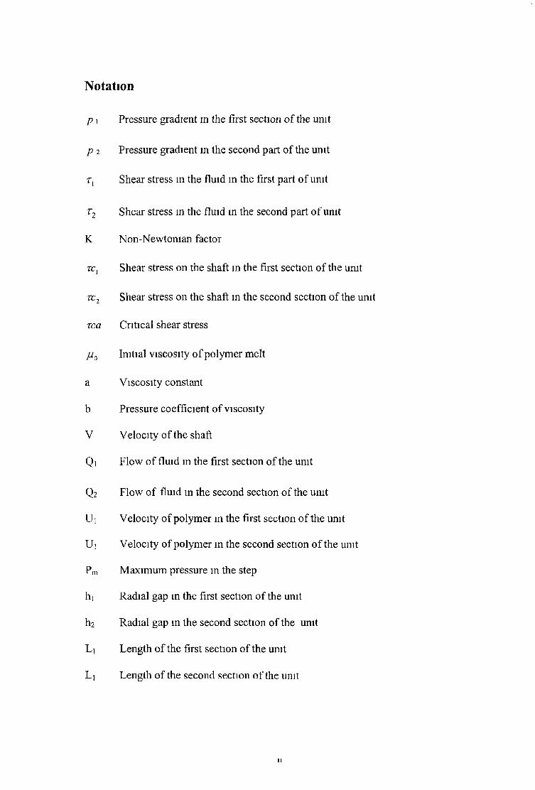
p 2 Pressure gradient in the second part of the unit
Tj Shear stress m the fluid in the first part of unit
t2 Shear stress in the fluid in the second part of unit
K Non-Newtonian factor
zc{ Shear stress on the shaft m the first section of the unit
t c 2 Shear stress on the shaft in the second section of the unit
tea Critical shear stress
juQ Initial viscosity of polymer melt
a Viscosity constant
b Pressure coefficient of viscosity
V Velocity of the shaft
Qi Flow of fluid m the first section of the unit
Q2 Flow of fluid m the second section of the unit
U 1 Velocity of polymer m the first section of the unit
Ui Velocity of polymer m the second section of the unit
Pm Maximum pressure in the step
hi Radial gap in the first section of the unit
h2 Radial gap m the second section of the unit
Li Length of the first section of the unit
Li Length of the second section of the unit
Notation
p i Pressure gradient in the first section o f the unit

Development of a Novel Rheometric Device for the Determination of Pressure Dependent Viscosity of non-Newtonian Fluids
Salma Akhter, BSc Eng
ABSTRACT
A new type of Rheometer has been designed based on hydrodynamic
principles Hydrodynamic pressure technique is a relatively new and innovative
technique for rheological studies of viscous non-Newtonian fluids These principles
have been extensively used for the last ten years for drawing and coating of strips and
wires The Rheometric Device consists of a rotating inner cylinder (shaft) in a fixed
hollow outer cylinder The complex geometry gap between the two cylinders is filled
with a viscous non-Newtonian fluid When the surface of the shaft is rotating inside
the hollow cylinder filled with a viscous fluid, shearing takes place and hydrodynamic
pressure develops the magnitude of which is dependent on the shape of the surfaces,
the viscosity of the fluid as well as the shear rate 1 e the speed with which the inner
solid cylinder is rotated The Rheometer has been developed to determine the
Rheological properties of viscous fluid at pressures of up to 100 bar and a shear rate
range of 500 to 4000 sec 1
Experimental procedure and methods have been outlined and a number
of experiments have been carried out to determine the effects of pressure and shear
rate on viscosity Included in the work are measurements of the pressure with
variation of the shearing speed and inserts Three different non-Newtonian fluids,
glycerine, and silicon with two different viscosities were used as the pressure
medium The experimental works were undertaken with glycerine keepingG O
temperature at 18 ± 1 C and silicon at 25+ 1 C for shearing speeds of between 0 25
m/sec-2 0 m/sec In the present study, theoretical models have been developed based
on the non-Newtonian characteristics and a shear rate viscosity relationship was
determined using the rheometer at different pressures by comparing the calculated
theoretical pressure distribution with the expenmental results
in

Additional expenmental work has been carried out using a Brookfield
viscometer to determine the effect of shear rate on viscosity at lower shear rates The
Newtonian or non-Newtonian, charactensties of glycerine, silicon was investigated by
using this viscometer Using the theoretical model the viscosity of the fluid was
determined at lower shear rates at atmospheric pressure Results from the new
Rheometnc Device and the Brookfield viscometer have been presented graphically
and new type of equations have been developed based on the expenmental results
using BDV and new Rheometer at the shear rates between 0-4000 Sec 1 and only at
atmospheric pressure
IV

Determination of Pressure Dependent Viscosity of non- Newtonian Fluids Using a Novel Rheometric Device
Contents
Page
Acknowledgements i
Notation 11
Abstract 111
Contents v
List of Figures and Plates ix
List of Tables xvi
1 Introduction and Literature Review 1
1 Introduction 1
1 1 Hydrodynamic phenomena 1
1 2 Rheology of non-Newtonian fluids 2
1 3 Variables which affect viscosity 3
13 1 Effect of pressure on viscosity 3
13 2 Effect of shear rate 5
13 3 Effect of temperature 6
13 4 Effect of flow characteristics 9
13 5 Critical Shear Stress 9

14 Literature Review 10
14 1 Background literature of hydrodynamicphenomena in drawing process 10
14 2 Background literature of polymer melts as alubricant in drawing process 12
14 3 Background literature of Rheometers and
Rheological research 14
1 5 Present Project and its aim 17
16 Overview of the Project 19
H y d r o d y n a m ic A n a ly s is 3 6
2 1 Introduction 36
2 2 Theoretical Analysis 37
2 2 1 Determination of the Pressure and the Coefficents of Viscosity Equation of non-Newtonian fluids 38
D e s ig n in g a n d C o m m iss io n in g o f th e R h e o m e tn c D e v ic e a n d T e s t P r o c e d u r e 4 7
3 1 General description 47
3 2 Instrumentation 48
3 2 1 Pressure Transducers 48
3 2 2 Digital Magnetic Pickup 49
3 2 3 Thermocouple 49
3 2 4 The Variable Speed Motor 49
3 2 5 Digital Tachometer 50
3 2 6 RDP Machine 50
33 Design of the Rheometnc Device 51
VI
3 3 2 Insert 2 52
3 3 3 Shaft 52
3 3 4 Pressure End plate 53
3 3 5 Shaft End Plate 53
3 4 Design of the Electrical Installation 53
3 5 Test procedure with the Novel Rheometnc Device 54
4 Experimental Equipment, Test Procedure, Material 68
4 1 The High Pressure Rheometnc Device andTest Procedure 63
4 2 Working Pnnciple of the Device 69
4 3 Pressure fluid 71
4 4 BROOKFIELD DIGITAL VISCOMETER 71
4 5 Test Procedure with the viscometer 72
4 5 1 Autozero 72
4 5 2 Spmdle Selection 72
4 5 3 Speed Selection and Setting 73
5 Results and Discussions 76
5 1 Introduction 76
5 2 Results of Pressure 76
5 2 1 Results of the Pressure distnbution 77
5 2 2 Results of Maximum Pressure Vs Speed 80
33 1 Insert 1 51
5 3 Determination of the Rheology
V ll

5 4 Effect of Pressure on Viscosity 83
5 5 Effect of Shear Rate on Viscosity 84
5 6 Discussions 125
5 6 1 Introduction 125
5 6 2 Discussion on the Test Procedure andthe Experimental Work 125
5 6 2 Discussions on the Analysis and theTheoretical Results 127
5 63 Error Analysis 128
6 C o n c lu sio n an d S u g g estio n s for F u rth er 130
6 1 Introduction 130
6 2 Conclusion 130
6 3 Suggestions For the Future Work 131
R eferen ces 133
A p p en d ix A 142
A p p en d ix B 1 4 7
A p p en d ix C
(Values of the coefficient 'a' and V) 81
vili

LIST OF FIGURES
C hapter N u m ber P age
C hapter O ne
Fig 1 1 Flow Curves for 0 92 polyethylene at 130 C 20
Fig 1 2 Viscosity vs Pressure for different shear
rates (0 92 Polyethylene 21
Fig 1 3 Flow Curve for ALKATHENE WVG23 22
Fig 1 4 Flow curve for POLYPROPYLENE KM61 23
Fig 1 5 Flow curves for RIGIDEX 24
Fig 1 6 Flow curves for POLYSTYRENE 25
Fig 1 7 Effect of shear rate on viscosity of ALKATHENE WVG23 26
Fig 1 8 Effect of shear rate on viscosity of POLYPROPYLENE KM61 27
Fig 1 9 Effect oft of shear rate on viscosity
of RIGIDEX 28
Fig 1 10 Effect of shear rate on viscosity of POLYSTYRENE 29
Fig 1 11 Effect of temperature on viscosity of polymer 30
Fig 1 12 Effect of temperature of WVG23,KM61, RIGIDEX
and POLYSTYRENE 31
IX

Fig 1 14 Nozzle-die unit (BISTRA) 33
Fig 1 15 Pressurised chamber 33
Fig 1 16 Pressure tube-die arrangement 34
Fig 117 Couette's viscometer, A is the mside guard nngs F and F' 35
C hapter Two
Fig 2 1 Parallel bore pressure unit 39
C hapter Three
Fig 3 1 Schematic diagram of the drawing bench 56
Fig 3 2 Pressure Unit 57
Fig 3 3 Pressure Cylinder 58
Fig 3 4 Insert 1 59
Fig 3 5 Insert 2 60
Fig 3 6 Shaft 61
Fig 113 Typical pressure tube and die 32
Fig 3 7 Pressure End Plate 62
X

Fig 3 8 Shaft End Plate 63
C hapter F our
Fig 4 1 Schematic Diagram of Pressure Unit Assembly 75
C hapter F ive
Fig 5 1 Pressure Distribution of Glycerine for the different shearing speed
at the Gap Ratio of 3 86
Fig 5 2 Pressure Distribution of Glycerine for different shearing speed
at the Gap ratio of 5 87
Fig 5 3 Pressure Distribution of Glycenne for different sheanng speed
at the Gap ratio of 8 88
Fig 5 4 Pressure Distribution of Glycenne at the sheanng speed of
0 5 m/sec for the different Gap Ratios 89
Fig 5 5 Pressure Distnbution of Glycerine at these sheanng speed of
1 0 m/sec for the different Gap Ratios 90
Fig 5 6 Pressure Distribution of Glycenne at the sheanng speed of
1 5 m/sec for the different Gap Ratios 91
Fig 5 7 Pressure Distnbution of Sihcon5 for different sheanng speed
at the Gap ratio of 3 92
XI

Fig 5 8 Pressure Distribution of SiliconS for the different shearing speed
at the Gap Ratio of 3 93
Fig 5 9 Pressure Distribution of SiliconS for the different shearing speed
at the Gap Ratio of 5 94
Fig 5 10 Pressure Distribution of SiliconS for the different Speed
at the Gap Ratio of 5 95
Fig 5 11 Pressure Distribution of Silicon5 for different sheanng speed
at the Gap Ratio of 8 96
Fig 5 12 Pressure Distribution of Silicon5 for the different sheanng speed
at the Gap Ratio of 8 97
Fig 5 13 Pressure Distribution of Silicon 5 at the speed of
0 25 m/sec for the different Gap Ratios 98
Fig 5 14 Pressure Distribution of Silicon 5 at the speed of
2 0 m/sec for the different Gap Ratio 99
Fig 5 15 Pressure Distribution of Silicon 5 at the speed of
12 5 m/sec for the different Gap Ratio of 3 100
Fig5 16 Pressure Distnbution of Silicon 5 at the speed of
0 25 m/sec for Gap Ratio of 5 101
Fig 5 17 Pressure Distribution of Silicon 5 at the speed of
0 25 m/sec for the different Gap Ratio of 8 102
Fig 5 18 Pressure Distribution of Siliconl2 5 at the speed of
0 5 m/sec for the different Gap Ratios 103
XII

Fig 5 20 Pressure Distribution of Silicon 5 at the speed of
1 Om/sec for the different Gap Ratio of 5 105
Fig 5 21 Maximum Pressure vs Speed for Glycerine for
The different Gap Ratios 106
Fig 5 22 Maximum Pressure vs Speed for Sihcone5 for
the different Gap Ratios 107
Fig 5 23 Maximum Pressure vs Speed for Silicone 12 5 for
the different Gap Ratios 108
Fig 5 24 Comparison of Maximum Pressure vs Speed for Glycenne
Silicon5 and Silicon 12 5 for the Gap Ratio of 5 109
Fig 5 25 Comparing the Theoretical Pressure Distribution of
Glycenne at 1 5 m/$ec for the Different values o f ’a' and V
with the Expenmental Results 110
Fig 5 26 Companson of the Theoretical Pressure Distribution of
Glycenne at 1 5 m/sec for the different Values of 'a'
with the Expenmental Results 111
Fig 5 27 Companson of the Theoretical Pressure Distnbution of
Silicone5 at the Speed of 1 0 m/sec for the different Values
of 'a' and V with the Expenmental Results 112
Fig 5 19 Pressure Distribution of Silicon 5 at the speed of
2 0 m/sec for the different Gap Ratios 104
Fig 5 28 Companson of the Theoretical Pressure Distribution of
Silicone5 at the Speed of 1 0 m/sec for the different Values of'a'
XIII

with the Expenmental Results 113
Fig 5 29 Comparison of the Theoretical Pressure Distribution of
Sihconl2 5 at the Speed of 1 0 m/sec for the different Values
Of 'a* and V with the Expenmental Results 114
Fig 5 30 Comparison of the Theoretical Pressure Distnbution of
Silicon 12 5 at the Speed of 1 0 m/sec for the different Values
of ’a’ with the Expenmental Results 115
Fig 5 31 Effect of Pressure on Viscosity for Glycenne 116
Fig 5 32 Effect of Pressure on Viscosity for Silicon5 117
Fig 5 33 Effect of Pressure on Viscosity for Silicon 12 5 118
Fig 5 34 Effect of Pressure on Viscosity for Silicon 5 and
Silicon 12 5 at the Shear Rate 2000 sec 1 119
Fig 5 35 Shear Rate vs Shear Stress of Glycenne, Sihcon5
and Siliconl2 5 using the Brookfield Viscometer 120
Fig 5 36 Effect of Shear Rate on Viscosity of Glycenne,Silicon5
and Silicon 12 5 Using the BROOKFIELD Viscometer 121
Fig 5 37 Effect of Shear Rate on Viscosity of Glycenne at
Atmosphenc Pressure 122
Fig 5 38 Effect of Shear Rate on Viscosity of Silicon5
at Atmosphenc Pressure 123
Fig 5 39 Effect of Shear Rate on Viscosity of Silicon 125
at Atmospheric Pressure 124
XIV

List of Plates
Chapter Three
Plate 3 1 Overallview of the ng 64
Plate 3 2 RDP machine, and Frequency Inverter 64
Plate 3 3 Electric motor and magnetic pickup 65
Plate 3 4 Pressure chamber 65
Plate 3 5 Pressure transducer and thermocouple 66
Plate 3 6 Electric Controller 66
Plate 3 7 Insert 1 67
Plate 3 8 End Plate 67
Plate 4 1 BROOKFIELD Viscometer 74
Chapter Page
XV

List of Tables
Chapter Number
Chapter 1
Table 1 1 Shear Rates Typical of Some Familiar Materials
and Processes

Chapter One
INTRODUCTION AND LITERATURE REVIEW
1. Introduction
11 Hydrodynamic phenomena
Hydrodynamic means dynamics of fluids under certain flow
conditions When a viscous fluid is present between the gap of the two solid surfaces
and one of the surfaces moves relative to the other hydrodynamic pressure develops
A common situation is when the fluid is flowing through a converging gap (like a
journal bearing) The magnitudes of this hydrodynamic pressure are dependent on
the shape of the surfaces, the viscosity of the fluid as well as the relative speed of
movement The mechanics of fluid pressure generation can be explained by the fact
that the moving surface drags the fluid into the gap formed between it and the fixed
surface and the relative motion between the moving surface and the fluid gives rise
to the pressure If the fluid is oil type then the generated pressure is not so high But
if it is of polymer solution type then the generated pressure is many times higher
However, for plastic processing equipment and food and mineral processing
industries the pressure generation due to hydrodynamic phenomenon could be a
significant design factor for the processing equipment This principle should be
advantageous for designing a new rheometer for determining the rheological
properties of viscous fluids such as glycenne and silicone, etc at higher than

atmospheric pressures The flow Characteristics of non-Newtonian fluids are
influenced by many factors, which are described m relation to the present work for
rheological studies of these fluids
1.2 R h eo lo g y o f n o n -N ew to n ia n flu id s
“Rheology” is a general term for the study of deformation and flow of
materials, it originates from the Greek word “rhein”, which means, “to flow”
Rheology is concerned with the flow and deformation of matenals experiencing an
applied force The term ‘Rheology5 was invented by Professor Bingham of Lafayette
college, Easton, PA, USA on the advice of a colleague, a Professor of Classics It
means the study of the deformation and flow of matenals as mentioned earlier This
definition was accepted when the Amencan Society of Rheology was founded in
1929 That first meeting heard papers on the properties and behaviour of such widely
differing materials as asphalt, lubricants, paints, plastics and rubber, which gives
some idea of the scope of the subject and also the numerous scientific disciplines
which are likely to be involved Nowadays, the scope is even wider Significant
advances have been made m biorheology, in polymer rheology and m suspension
rheology There has also been a significant appreciation of the importance of
rheology m chemical processing industries Opportunities no doubt exist for more
extensive applications of rheology m the biotechnological industries Rheology is
becoming more and more important in plastic industry, both m areas of development
and processing [1] Other applications of rheology are as follows (l) Pumping
slumes-matenals transport (11) Thickening and de-watenng of mineral slurries
2

(in) Filtration (iv) Forming materials e g brick and ceramic products (v) Pamt
manufacture e g non-drip paints (vi) Reactions involving mineral slurries e g gold
extraction (vn) Food chemistry and manufacture-texture of ice cream, pasta,
desserts, processed meats, cosmetics chemistry (vm) Drilling mud for petroleum
industry (ix) Polymer chemistry-solution and melts (x) Plastohydrodynamic wire
drawing and wire coating 1 e rheological properties required for good coating
performance
In recent studies of thermoplastic injection moulding, sophisticated
rheological techniques have been employed to characterise the viscous behaviour
Since the findings of rheology are of fundamental importance for the development,
manufacture and processing of innumerable products Without rheology, nothing in
materials and process engineering can function today Rheometry is the technology,
which involves the rheological measurement of fluids The flow characteristics of
non-Newtonian fluids are influenced by many factors, which are described m relation
to the present work for developing a new type of rheometer for rheological studies of
glycenne, silicone, liquid honey, polymer melt etc
1 3 Variables which affect viscosity
13 1 The effect of pressure on viscosity
Several theories suggest that the free volume [2-6] determines the viscosity of
a fluid The free volume of a fluid is defined in various ways, but a common
definition is the difference between the actual volume and a volume in which such
close packaging of the molecules occurs that no motion can take place The greater
3

the free volume the easier it is for flow to take place The viscosity of liquids
increases when the pressure is increased because the distance between the molecules,
and hence their mobility decreases At very high pressures no free volume is left in
the liquid which becomes solid [7] Free volume increases with temperature because
of thermal expansion However, the most direct influence on free volume should be
of the pressure An increase in hydrostatic pressure decreases the free volume and
increases the viscosity of a fluid Viscosity, by definition, is the internal resistance to
shearing stress due to mtermolecular forces of attraction It is thought that if those
forces of attraction are encouraged, the apparent viscosity of the polymer, which is
one of the most important properties of these materials, may be increased
Westover [8] described a double piston rheometer for measunng viscosity as
a function of pressure at 172 MN/m2 He found that the viscosity of polystyrene
increases by over a hundred times and the viscosity of polyethylene increases by a
factor of five at a constant rate of shear as the pressure was increased Maxwell and
Jung [9] , and Choi [10] demonstrated that the effect of hydrostatic pressure on the
apparent viscosity of branched polyethylene and polystyrene at constant shear and
temperature are appreciable and should not be neglected Cogswell [11] suggested
that the effect of an increase in pressure may be linked to that due to a drop in
temperature He observed that for low-density polyethylene, an increase in pressure
of 100 MN/m2 had the same effect on viscosity as that due to a drop in temperature
of 53° C within the melt range It had been noted that at very high pressure (above
140 MN/m2) the melt tended to recrystallise and in consequence the melt acted melt
acted like a solid plug [12] For this reason, pressure viscosity measurements are
often conducted at relatively high temperature Since the work carried out by
Westover appears to be the most comprehensive, his results are used to determine the
4

pressure coefficient of viscosity Figure 1 1 shows the effect of pressure on shear
stress-shear rate curves and figures 1 2 shows how shear rate effects the influence of
pressure on viscosity
13 2 Effect of Shear rate
Table 1 1 shows the approximate magnitude of shear rates encountered in a
number of industrial and everyday situations in which viscosity is important and
therefore needs to be measured The approximate shear rate involved in any
operation can be estimated by dividing the average velocity of the following liquid
by a characterstic dimension of the geometry in which it is flowing (e g the radius of
a tube or the thickness of a sheared layer)
Table 1 1 Shear rates typical of some familiar materials and processes
Situation Typical range of shear rates(s15
Application
Extruders 10°-102
1 2Chewing and swallowing 10 -10
Dip coating 101 -102
Polymers
Foods
Paints, confectionary
Mixing and stirring
Pipe flow
Spraying and brushing
io 1 -103
10° - 103
103- 104
Manufacturing liquids
Pumping, Blood flow
Spray-drymg, painting Fuel atomisation
Lubrication 103- 107 Gasoline engines
5

Since the non-Newtonian viscosity behaviour will be dealt with m this
project, it is important to first define what the Newtonian behaviour is, m the context
of the shear viscosity A Newtonian fluid has the characterstic that the shear
viscosity does not vary with shear rate [1] For non-Newtonian behaviour, the
apparent viscosity decreases as the rate of shear increases Figures 13, 14, 15 and
1 6 show the effect of shear rate on shear stress where the influence of temperature
may be noticed These curves were produced by extruding polymer melts (Alkathene
WVG23, polypropylene KM61, Rigidex (HDP) and Polystyrene) through an
extrusion rheometer at different temperatures A non-lmear relationship is seen to
exist between shear stress and shear rate The viscosity of the polymer may be
calculated at any known shear rate by measuring the slope of the curve A Newtonian
fluid under shear stress condition exhibits linear relationship with shear rate where
the slope of the line represents the viscosity of the fluids Figures 1 7, 1 8, 1 9 and
1 10 show another way of representing the effect of shear rate on viscosity, where the
viscosity may be read off directly from known shear rate values (For a Newtonian
fluid this curve would be a horizontal straight line)
13 3 Effect of Temperature on viscosity
An mciease m temperature generally decreases the viscosity of the fluids
This effect vastly differs for different types of polymer Figure 111 shows typical
changes m viscosity against temperature at zero shear rates The slope of each line
measures the activation energies has more deterioration effect on viscosity compared
!to those of lower activation energies This energy is a function of polarity in
6

polymers and the most non-polar polymers such as polyethylene with very small
inter-molecular forces have low activation energy
Flow occurs when polymer molecules slide past each other and the ease of
flow depends on the mobility of the molecular chains and the forces of holding the
molecules together That an increase m temperature reduces viscosity is widely
known and m general is a property easily understood Viscosity and temperature for
a Newtonian fluid may be related by an Arrhenius equation of the form
|i=Ae E/RT
This equation together with a knowledge of A, a constant, and E, the
activation energy, enables to calculate the coefficient of viscosity (i for an absolute
temperature T, R is the universal gas constant A second (empirical) equation is often
used for melts This is ja=a ”bt where both a and b are constants To obtain a
fundamental explanation of the difference in temperature dependence of viscosity
between different polymers a number of attempts have been made The application of
“free volume theory” is most successful This theory suggests that at some
temperature T0 there is no “free volume” between the molecules This free volume,
f, is postulated to increase linearly with temperature so that at Tg the fractional free
volume has a value fg
The expansion coefficient otf is defined by the equation,
F = fg+ otr (T-Tg)
7

It has been proposed that fg has the universal value of 0 0025 and otf is a universal
value of 4 8x10 '4 Williams, etal [13] have argued from this that the viscosity r| of a
polymer at temperature T may be related to its viscosity r|a an arbitrary reference
temperature ta by the equation,
± _ _ _ c ; ( T _ ~ Ta)
C2° + T - T a
If the arbitrary temperature is taken as Tg then the above equation becomes
n. C2s + T - T g
In this case Cig=l/2 303 fg= 17 44 and C2g=l/2 303 CiEa f= 51 6 have been
proposed as universal constants The equations are known as the WLF equation [14]
DIENES [15] believed that as the temperature increases the molecular arrangements
withm the polymer change more towards random configuration, therefore, it
becomes easier for the polymer to flow at higher temperatures Figures 1 11 and 1 12
show the variation of viscosity versus temperature for these polymers at zero shear
rates These graphs do not represent the complete behaviour since viscosity
measurements are affected by pressure, shear rate, temperature etc and it is
necessary to include these effects on viscosity of polymer melts

13 4 Effect of Flow Characteristics
In the plasto-hydrodynamic pressure unit the polymer melt is subjected to
very high shear rates and pressures, much greater than those capable of being
developed m any extrusion rheometer The presence of cntical shear stress at low
shear rate decreases the coating thickness, as concluded by Crampton[16] However
it is also believed that, the poor performance of the unit at higher drawing speeds is
related to a combination of factors such as shear rate, melt flow instability, partial
crystallisation, compressibility etc and not just by the critical shear stress The high-
pressure generation is believed to have the effect of increasing the melt viscosity in
the unit Crampton maintained the temperature at a steady value when the tests were
conducted thus minimising the effects inherent with changing temperature However
to understand these effects fully further investigation is needed
13 5 Critical Shear Stress
The critical shear stress is the stress at which the uniformity of the non-
Newtonian fluids such as polymer melt flow ceases to exist Several workers [17-19]
investigated this phenomenon and they showed that certain flow defects are
associated with the polymer Ripple, Bamboo, Spiral, ZigZag or Helix for different
types of polymers The terms “Melt fracture”, "Elastic turbulence” and “Flow
disstortion" have been used to describe this effect
9

1 The critical Shear Stress (C S S ) has values in the region o f 0 01 to 1 OMN/m2
for most polymers
2 The C S S is independent of the die length and diameter
3 The C S S does not vary w idely with temperature
4 The flow defects always take place when non-Newtonian fluids are
involved
5 A discontinuity m the viscosity shear stress curves occurred
6 The C S S was shown by the cinematography method to take place in the die
1 4 Literature Review
14 1 Historical background of hydrodynamic lubrication
A s the demand for higher quality wire increased, better lubncation proved
necessary to promote efficiency, surface finish, quality, heat dissipation and a
reduction m production time The latter may be summarised as (i) Reduced drawing
time (n) Reduction o f number o f inter- pass heat treatment (111) Elim ination of
redrawing time ( i v ) Reducing down time due to changing dies because o f excessive
wear Chnstopherson and N aylor [20] pioneered the development o f hydrodynamic
lubncation m wire drawing They employed a long tube, with very close tolerances,
attached to the front end o f a conventional die as shown m Figure 1 13 O il was used
for lubrication purpose and as the wire was pulled through the dies, it pressunsed the
lubncant by viscous action and fed into the die inlet Th is pressunsed lubncant then
completely separated the wire from the die, preventing metal to metal contact
However, there is a general agreement on the following points
1 0
Expenm ental results provided by them showed evidence o f deformation o f the wire
m the tube before the die entrance Although it was shown that hydrodynamic
lubrication was achieved under the designed conditions, the pressure nozzle had to be
placed vertically and was o f such a length that the wire industry found it too
inconvenient to put it into practice
W istench [21] carried out experimental work on the forced lubrication based
on a pressure tube system Soap powder was used as the lubricant m a short nozzle,
which was attached to the entry side o f the die Experim ental results showed that the
speed, temperature and the tube gap had a direct effect on the property o f the film
thickness produced He also noted that o il produced a thicker film than soap A
schematic diagram o f the unit used by W istench is shown in Figure 114
Tattersal [22] published a detailed analysis o f plasto-hydrodynamic
lubncation action m wire drawing taking some rheological and m etallurgical
properties o f the process into account Experimental results and theory showed that
these were in reasonable agreement More recently Chu [23] using the work of
Tattersal presented a chart for the mlet tube he designed Subsquently Bedi [24]
introduced an analysis for wire drawing assuming complete hydrodynamic
lubncation Studies o f the lubricant film thickness which would be developed under
practical drawing conditions have been presented m references [25-26] M iddlem iss
[27] improved the previously used drawing unit by using an externally pressurised
lubrication system
Kalm ogov et al [28] also conducted experimental work on tube sinking under
conditions o f hydrodynamic action In contrast to sim ilar devices for wire drawing
there was no seal between the nozzle and the die, because the lubncation process in
tube sinking was much lower Soap powder was used as the lubncant in that work
11

Bloor et al [29] produced a theoretical analysis for elasto-plasto hydrodynamic
lubrication action for strip drawing through wedge shaped dies They took account o f
elastic component in the strip at entry and exit to the die and the pressure and
viscosity characteristics o f the lubricant It has shown that by comparing the
magnitude o f the predicted lubricant film thickness that hydrodynamic lubrication
could be accomplished during the process
Double die arrangements were developed by Orlov et al [30] Their version of
the pressure nozzle/die is shown m Figure 1 15 The lubricant is transported into the
chamber formed by the exit cone o f the pressure die and the entry part o f the drawing
die, where the pressurised lubricant provides the hydrodynamic lubrication dunng
drawing Although claim was made for reduced power consumption and reduced die
wear there was however a lack of substantial evidence to support this claim
14 2 Background Literature of Polymer Melt as a Lubricant in Drawing
Process
Polymers were first used as lubricants in deep drawing and hydrostatic
extrusion They were chosen because o f the radically differing charactenstics from
either soap or o il There are many important differences between the rheology o f
molten polymer and conventional lubricants such as o il The most obvious o f these is
the very high viscosity o f polymer melts at higher temperatures, which would
preclude the use o f o il as a lubricant Non-Newtonian lubricants have been
previously investigated for journal bearing [30] and these have been found to be
advantageous for bearings subjected to oscillatory load which induce fatigue loading
The use o f a polymer melt as the coating material in the drawing process was
12

suggested by Symmons and Thompson [31] They investigated the adherence o f a
polymer coat onto the drawn wire There was some hydrodynamic lubncation
achieved but not as much as expected Both Stevens [32] and Cramp ton [33]
conducted experiments which showed that polymer coating o f wire was possible,
depending on the temperature, viscosity o f the polymer and drawing speed o f the
wire The experiments they carried out reduced the cross-sectional area o f the wire
They also noted that the polymer coat thickness on the wire decreased as the drawing
speed increased The apparatus used was a m odification o f Cristopherson tube A
schematic diagram o f this unit is shown m figure 116
Other experimental work carried out by Crampton et al [34] has
shown that effective reduction o f the wire diameter should be possible using a
polymer melt m conjunction with a stepped bore tubular unit only Panwher et al [35-
37] reported work carried out on the dieless tube sinking process and presented an
analytic solution based upon Newtonian characteristics Subsequently Panwher [38]
analysed the system taking account o f the Non-Newtonian charactensties o f the
polymer Symmons et al [39-40] presented analysis o f a die-less wire drawing
process using a viscosity-pressure and viscosity - temperature relationship o f
experimental form For the deformation o f strip using a stepped parallel bore unit,
Memon et al [40-44] also published theoretical and expenmental works
Parvinmehr et al [45-49] carried out sim ilar experiments to Crampton’s but
used two different types o f pressure tubes m which the smallest diameter o f the tube
was greater than the in itial diameter o f the wire being drawn The units had no
reduction die since Crampton and other researchers previously noted that
deformation started to occur before the entrance to the reduction die The two
pressure tubes he used m his experiment were o f stepped and tapered bored nature
13
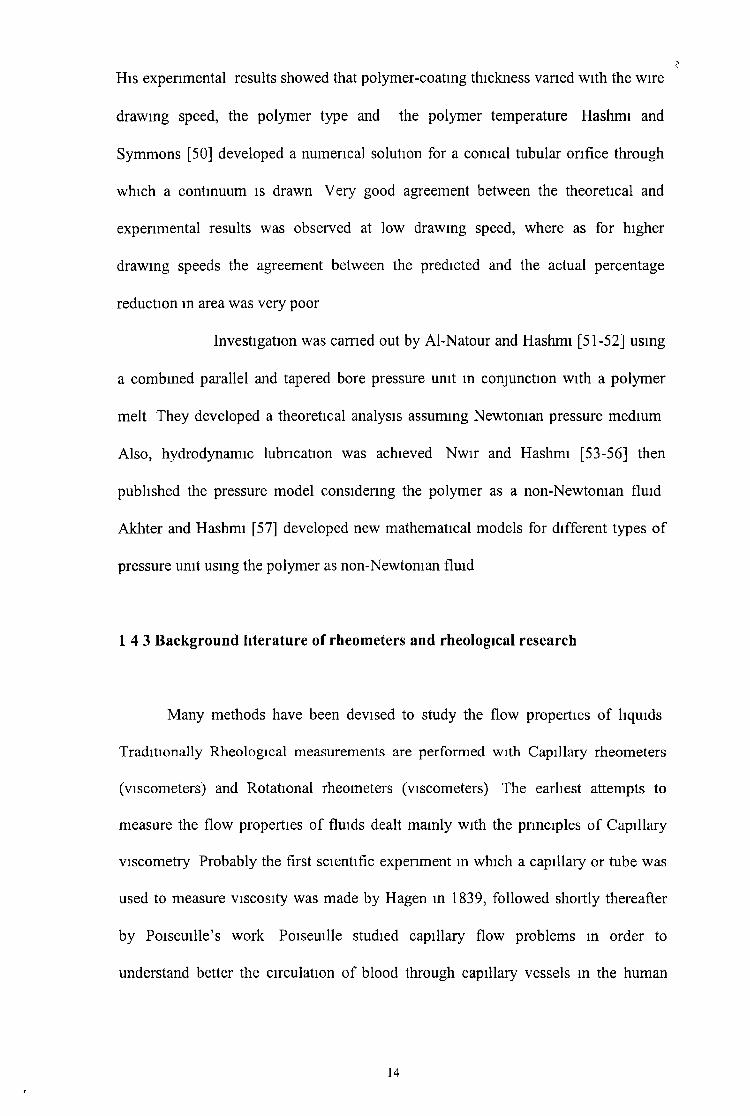
H is expenmental results showed that polymer-coatmg thickness varied with the wire
drawing speed, the polymer type and the polymer temperature Hashm i and
Symmons [50] developed a numerical solution for a conical tubular orifice through
which a continuum is drawn Very good agreement between the theoretical and
experimental results was observed at low drawing speed, where as for higher
drawing speeds the agreement between the predicted and the actual percentage
reduction m area was very poor
Investigation was earned out by Al-Natour and Hashm i [51-52] using
a combined parallel and tapered bore pressure unit m conjunction with a polymer
melt They developed a theoretical analysis assuming Newtonian pressure medium
A lso , hydrodynamic lubncation was achieved N w ir and Hashm i [53-56] then
published the pressure model considenng the polymer as a non-Newtonian fluid
Akhter and Hashm i [57] developed new mathematical models for different types o f
pressure unit using the polymer as non-Newtonian fluid
14 3 Background literature of rheometers and rheological research
Many methods have been devised to study the flow properties o f liquids
Traditionally Rheological measurements are performed with Capillary rheometers
(viscometers) and Rotational rheometers (viscometers) The earliest attempts to
measure the flow properties o f fluids dealt mamly with the principles o f Capillary
viscom etry Probably the first scientific experiment m which a capillary or tube was
used to measure viscosity was made by Hagen in 1839, followed shortly thereafter
by Poiseuille’s work Poiseuille studied capillary flow problems m order to
understand better the circulation o f blood through capillary vessels in the human
14

body He discovered the relation slip (known as the Hagen Poiseuille law) between
flow rate and pressure drop Th is discovery was the foundation o f capillary
viscom etry W ith developments m hydrodynamics and advances in the technology of
non-Newtonian fluids, capillary viscometry became a reliable method o f measunng
the flow properties o f a fluid [58] The capillary viscometer provides an
improvement m shear capability Novak and Wmer [59] used a capillary viscometer
to measure the viscosity o f polymer/ mineral o il mixtures at pressures to 0 3 GPa and
shear stresses to 105Pa They reported Newtonian behaviour m two ranges o f shear
stress at low shear stress a “ first Newtonian” associated with the viscosity o f the
blend and above about 104 Pa shear stress, a transition to a “second Newtonian” for
which viscosity was again rate independent but with a value reduced to nearly that o f
the mineral o il solvent W ith the capillary technique the hydrostatic pressure vanes
across the length o f the capillary requmng foreknowledge o f the effect o f pressure on
material parameters
Couette devised the first practical rotational viscometer m 1890 [60]
Couette’s Concentric cylinder viscometer consisted o f a rotating cup and an inner
cylinder which was supported by a torsion wire and rested m a point beanng in the
bottom o f the cup (fig 117) 23 years later Hatcheck described a modified version o f
the Couetteviscometer, which improved on the design o f the guard rings and
m inim ised effects with very low viscosity fluids Many aspects o f the new theones
(non-Newtonian or complex fluids) pioneered by Reiner, Bingham , et a l , required
innovations is design Barber et al [61] operated a rotational viscometer at
atmosphenc pressure with gaps approaching one micron Shear rates as high as
106sec_1were obtained However the shear stress was lim ited to 104 Pa Galvm [62]
developed a high pressure, high shear rate capillary viscometer It was used in a
15
lubrication research laboratory that covers a wide range o f rate o f shear at ambient
pressures substantially above atmospheric pressure and at various temperatures
A new slit rheometer with a continuously adjustable gap was developed to
characterise the shear V iscosity material functions o f structured fluids (suspensios,
dispersios, gels) as a function o f deformation rate and temperature [63] The
rheology and hydrodynamic analysis o f grease flows m a circular pipe was
investigated by Young [64] Rheological properties and pumping characteristics o f
two greases were investigated in the temperature range o f 5 ° C t o 3 5 ° C The high
pressure rheology o f a soap-thickened grease and the base o il has been characterised
using a falhng-body viscometer, high pressure couette viscometer, and a high
pressure penetrometer by Scott [65] He demonstrated the modified Bingham model
to describe the experimental observation A modified Bingham type rheometer,
designed for operation at temperature o f up to 500°F and pressures o f up to 200 p s l
is described by Nasan [66]
The relationship o f w all shear rate for closed couette flow has been
determined for power law fluids with a helical barrel rheometer [67] The principle
o f this rheometer is based upon measuring the pressure differential across one flight
o f special extruder wherein the helix is cut m the barrel rather than m the screw A
correlation for the pressure and temperature dependence o f viscosity is demonstrated
by Jagadish [68 ] Mamdouh et al [69] studied the rheological properties o f silicone
fluids (polydim ethylsiloxanes) Their studies include the depiction o f the rheological
fingerprints o f two PDM S solutions with the zero-shear viscosities 1000 and 30000
m Pa’s For the sake o f brevity they call these solutions PDM S1 and PDM S30,
respectively A lso included m the study are the transient shear stress responses, the
measurements o f yeild stresses, the thixotropy, and the creep-recovery tests Their
16
experiment shows the influence o f temperature on the rheological fingerprints o f
PDM S1 and PDM S30 PDM S1 solutions exhibit Newtonian behaviour and their
viscosities decrease by almost 45% when the temperature is raised from 10 to 50° C
However, PDM S30 shows two distinct ranges o f Newtonian and non-Newtonian
flow behaviour Over the in itial range o f Newtonian flow, the viscosity o f PDM S30
decreases with temperature from 10 to 40° C and slightly increases at 50° C
Compamk et al [70] studied the effect o f chain length and ion size on the
viscosity and ion conductivity o f poly (dim ethylsiloxane) systems They applied free
volume, Arrhenius type viscosity, and ion conductivity models Graebhng et al [71]
studied the viscoelastic properties o f poly (dim ethylsiloxane)-poly(oxyethylene)
blends They charactensed the polymer blends by high values o f the storage
modullus at low frequencies and by long relaxation times The related the rhelogical
behaviour to a few physically significant parameters such as the zero-shear viscosity
o f phases, the dispersed particle size, and the mterfacial tension between phases
A llco ck et al [72] described the importance o f PDM S applications in medicine,
which is due to its resistance to blood fluids
1 5 Present Project and its aim
Th is thesis outlines the author’s effort m the area o f non-Newtonian
fluid rheology A novel rheometnc device, using a stepped bore unit is developed
based on hydrodynamic principles Th is new technique would be useful in
determining the viscosity o f non-Newtonian fluids at different shear rates and high
pressures The experimental work was earned out and the theoretical model has been
developed m conjunction with the experimental work Included m this work are,
17

insert and determination o f viscosity and coefficients o f the viscosity equation in
conjunction with the experimental results
The scope o f the present design and research is to
a) Design and development o f an experimental device permitting the
determination o f pressure-dependent viscosity o f non-Newtonian fluids
b) Measure the developed pressure in the Rheometnc unit for different types o f
fluids at different with the shear rates, and for different gap geometncs
c) To develop a mathematical model for the prediction o f various parameters
involved m the process such as pressure, viscosity, shear rate, viscosity,
coefficients o f the viscosity equation m conjunction with the experimental
results
d) To determine the viscosity o f the different types o f fluids at different
pressures developed at different shear rates
e) To study the effects o f pressures on the viscosity o f the fluids which is
developed m the unit
f) To measure the viscosity o f different fluid with a Brookfield viscometer
with different shear rate and to determine the effect o f shear rate on
viscosity at the lower shear rate range
g) To develop a new type o f equation at the shear rate range 0-4000 Sec 1 and
only at atmospheric pressure
h) To discuss the viab ility o f the process and its limitations m relation to
practical applications
measurement of the variation of pressures with speed and changing the fluid, the
18

The details and background o f the investigation are presented m this thesis as
follow ing
In chapter one, a background literature o f the rheology o f non-Newtonian
fluid and the effect o f pressure, shear rate and the temperature on viscosity o f fluids
as w ell as the literature review o f the hydrodynamic phenomena and its presence in
wire drawing process have been presented The aim o f the research is also included
m the first chapter The theoretical analysis for the rheometer is given in chapter two
A discussion on the equipment used during the course o f tests is given in chapter
three, also the design o f the pressure unit is discussed m details in chapter three The
materials and the equipment used during the course o f the tests and the experimental
procedure is given m chapter four The experimental results using the new
rheometnc device and the Brookfield Viscom eter are given in chapter five The
discussions are also given m this chapter F in a lly, chapter six states relevant
conclusion and gives suggestions for both theoretical and experimental future work
1 6 Overview of the Project
19

MAX
IMU
M
SHEA
R ST
RESS
LB
F/IN
F IG 1 1 Flow Curves for 0 92 polyethylene at 130°C [49 ]

0 50 100 150 2 0 0PRESSURE (MN/m‘2)
Figure 1 2 V isco sity vs Pressure for different shear rates (0 92 Polyethylene 130°)[49]

0 0 . 5
F i g l 3

no',=110 N sec/m
1 . 5
Shear rate ( 104/sec)
Flow Curve for A L K A T H E N E W VG23

S h e a r S t r e s s ( M N / m 2)
f - H S H A R K S K IN F O R 2 0 0 °C '
— S H A R K S K IN F O R 230°C
I«— S H A R K S K IN F O R 260°C
►|< IN F E R E E D M E L T F R A C T U R E J;o=265Nsec/m2
K l= 8 x l0 n m/N2
|i0=200N sec/m2 K l= 1 0 x l0 n m/N2
|.i0=160N sec/m2 K l= 1 3 x l0 “ m/N:
— 2 0 0 C
2 3 0 C
2 6 0 C
1 1 . 5
S h e a r R a t e ( 1 0 4/ s e c )
Fig I 4 Flow curve for P O L Y P R O P Y L E N E K M 6 1

S h e a r S t r e s s ( N / m 2 ) x 1 0 5
S h e a r R a t e ( 1 0 4/ s e c )
F ]g 1 5 Flow curves for R IG ID E X !

F ig 1

— M ELT FRACTURE FOR 230°C " MELT FRACTURE FOR 240°Cy
— 2 3 0 Ci
- i - 2 4 0 C
2 5 0 C_______________________!___________________ t__________________
0 . 4 0 . 6 0 . 8 1
S h e a r R ate ( 1 0 4/ s e c )
6 Flow curves for POLYSTYRENE '

V i s c o s i t y ( N s e c / m 2)
S h e a r R a t e ( 1 0 4/ s e c )
Fig 1 7 Effect o f shear rate on viscosity o f ALKATHENE WVG23i

V i s c o s i t y ( N s e c / m 2)
Fig 1 8 Effect o f shear rate on viscosity o f P O L Y P R O P Y L E N E K M 61

V i s c o s i t y ( N . s e c / m 2)
S h e a r R a t e ( 1 0 4 / s e c )
F ig 1 9 Effect of shear rate on viscosity o f R IG ID E X

V i s c o s i t y ( N s e c / m 2)
S h e a r R a t e ( 1 0 4\ s e c )
Fig 1 10 Effect o f shear rate on viscosity o f POLYSTYRENE

100
10
1 o
V i s c o s i t y (N s e c / m 2)
1 0 0 0 / K
Fig ,111 Effect o f temperature on viscosity o f polymer

VI8COSITY N aec/m-2
1000/ K
F ig 112 Effect o f temperature on viscosity o f W VG 23, KM 61, R IG ID E X
and P O L Y S T Y R E N E

WIRE HIGH PRESSURE SEAL 01E
F ig 1 13 Typical pressure tube and die
32

IRONING OIE PRESSURC INLET
F i g l 15 Pressurised chamber
33

Fi g l 16 Pressure tube-die arrangement

I
I ~

Torsion wire
Guard ring
Fig 1 17 Couette's viscometer, A is the inside guard rings F and F f

Chapter Two
HYDRODYNAMIC ANALYSIS
When a solid surface is rotated within another surface (orifice) filled with a viscous
fluid, sheanng takes place and in addition to the shear force a hydrodynamic pressure is
generated The magnitude o f the sheanng and the pressure depends upon the speed with
which the solid surface is rotated, the viscosity o f the fluid and the geometncal
configuration o f the unit In order to verify the mechanics o f the process o f hydrodynamic
pressure development within the unit it is important to develop a suitable mathematical
model assuming non-Newtonian charactenstics Th is chapter outlines details o f a model
developed by the author for the proposed high-pressure rheometer
Rheologies o f fluids were discussed and several mathematical models developed, for
wire drawing were reviewed m chapter one Theoretical and expenmental works have also
been carried out to observe the effectiveness o f different lubncants and to calculate the film
thickness dunng deformation process m the presence o f hydrodynamic lubncation Different
types o f Rheometers have been discussed in chapter one Theoretical solutions for a novel
plasto-hydrodynamic die-less drawing process were presented m references [46-50] for
circular cross-section wires and rectangular strips
In the present study the geometrical configuration is different from the previous
researchers A non-Newtonian plasto-hydrodynamic analysis o f the process is presented for
2 1 Introduction
36

a stepped parallel gap in which glycerine and silicone is used as the pressure medium The
effects o f shear rate and pressure on the viscosity o f glycerine and silicone, together with the
shear stress are included in the analysis
2 2 Theoretical analysis
The follow ing analysis is based on the geometrical configuration shown in figure 1
To formulate the analysis the follow ing assumptions were made
1 Flow o f non-Newtonian fluid is isothermal
2 Flow o f non-Newtonian fluid is axial
3 Flow o f polymer is laminar
4 Thickness o f the fluid layer is small compared to the dimension o f the stepped gap
rheometnc unit
Analysis o f the parallel gap rheometnc unit is presented m two parts
1 Determination o f the pressure in thb unit
2 Determination o f the viscosity o f polymer within the unit and the coefficients o f the
viscosity equation
37

2 21 Determination of the pressure and coefficients of viscosity equation of non- Newtonian fluids
Two different equations are generally used to express the shear stress and
shear rate relation for a polymer solution The first is a power law equation given
by
' d U 'dy ( 1)
Th is equation is applicable for any type o f fluid Here n is the power law index which
equals to 1 for non-Newtonian fluid, greater than 1 for a dilettante fluid and less than
1 for psudoplastic fluid In this equation x is the shear stress, |i is the viscosity
coefficient for power law fluid andr dU^
\ dy jis the shear rate
The second is an empirical equation relating shear stress and shear rate o f a
viscous fluid suggested by Rabinowitch [12] in the form,
x+ K x 3 = ¡idy J
(2 )
Th is equation was later used by Hung and Muster (74) to determine the non-
Newtonian flow in a step bearing and also by Swamy et al (75) to calculate the load
capacity o f a finite width journal bearing Other workers have also used this equation
to analyse the behaviour o f non-Newtonian fluids [33,49] In equation (2) K is the
non-Newtonian factor, \i is the viscosity of the fluid, x and\ dy j
are the shear stress
38

and shear rate respectively In the analysis, which follows, is based on the second
empirical equation
Flow o f non-Newtonian fluid in the parallel stepped gap unit is divided into two sections
The first section being the entry part of the unit before the step and the second section being
the tube after the step
» insert \
Figure 2 1 Parallel Stepped gap rheometnc pressure unit
In the first part o f the unit in F ig (2 1) the relationship between the pressure and shear
stress gradient is given by
' d x xd x )x (2)
Integration with respect to y gives,
t , = P , 'y + x c , (3)
where Tc, is the shear stress at y = 0 and P , ' =(dp/dx), is constant across the gap
39

Substituting equation (3) into equation (1) becomes,
P , 'y + x c , + K (P , 'y + x c , )3= n ( ^ - ) idy
or
dU
, dyK y J \
= p l'y+ rc ] + K ( p '3y +2C,3 + 3pi'2y \ +3zc,2pl'>0
After integration equation (4) becomes
u , = + — + — + iC iV + A '2 A c , + 1 K l2p ] y ) + c ,2ju n M ^ 2
where C j is the constant o f integration,
The boundary conditions are,
(a) at y = 0, U j = V a n d ( b ) at y = l/15 U t = 0
Since at y = 0, U , = V hence C } = V hence equation (5) becomes

Now, let
h=\PA, M ,= i p , V ,
And
N | = i ^ + ^ Ä + I / V V ,khx 2k 4
So that,
rc ,3 + J xrc , 2 + M ,rc , + iVr1 = 0 (8)
A lso , let
Substituting for from equation (8) into (9) we get,
('A - y ) 3 + 7, W - y ) 2 + ( * - y ) 2 + A/, ( 4 - ^ ) 2 + N t = 0
(9)
W hich, after substitution for , M landN1 from above and sim plification becomes,
<f>' + 0 , ( — + |2^ , 2 ) + — = 0' ’ /c 4 ' kh,
41

which may be written as
(10)
1 1 2 ,
4 = - + - / » hj ' k A
and
kh j
Equation (10) is a cubic equation, which can be solved by applying Cardan’s formula as
outlines in Appendix B
I I I I<*, = [ - q + i q ^ V l ’ + I - q - ( q 2 + ^ ) 5 ] 5
Substituting the values o f 0, ,t A i, B i and Ji m above equation becomes,
jLW JU2V2 1 1 1TC, = + ( ^ T T + — ( — + - A ’2 A,2)3) 2) 3 +
2 K \ A K \ 21 K 4
( - — +— ( - + - Pi 2 K f y f - - Pi h a i)2Khi A K \ 27 K
The flow o f polymer gives Q x = J U, dy ( 12)0
Substituting for U x from equation (6) into the above equation and integrating gives,
42

A lso the steady state flow gives, — ( 0 = 0 Differentiating equation (13) and setting itdx
equal to zero we note that the nght hand side o f equation (13) is constant A s such xc, and
hence from equation ( 11)
Pi = dx J |= const =
where p m is the pressure at the step and /, is the length o f the first section o f the unit
Continuity o f flow gives, Q j “ Q 2 and therefore it is necessary to establish the flow
equations for the second part o f the unit before P m can be predicted The steady state flow
in the second part o f the unit gives,
dpdx dy y 2
The boundary conditions are as for part one, so that shear stress m the second unit becomes

rc, = ( - ^ + ( ^ i r + i ( ^ + TA'2V ) 3)2)5 +1 1
2Kh, '4K 2h,2 27 K 4
1 1
2 Kh, 4K h, 21 K 4
And the flow becomes,
p 2'h2 vc2h2 KQ2 = - ———+ + —6// 2(jl h
i3 7 5 3 7 2 12 7 4 2 t j 3h2 rc2 h2 p 2 h2 rc2 rc2 h220
+ + K/z? (15)
Again from steady state flow, — ( g 2) = 0 , Thus differentiating equation (15) and notingdx
that t c2 = constant we have , /Pi
d p \ _ q _ p m where is the pressure at the step
ydX;2
and 12 is the length o f the second section o f the unit It is shown that the pressure profile m
the first and the second section o f the unit is linear It is known that pressure increases the
viscosity o f polymers and this effect should be included m the analysis for a satisfactory
solution W ith reference to Figure 1 2 a generalised equation relating viscosity and pressure
may be shown to take the form [49]
ju = M +a + bp
r
where, a and b are constants and ¡u is the in itial viscosity o f non-Newtonian at ambient
pressure, y is the apparent shear rate and is given by y = v/h
44

section
The apparent shear rate m the first section is v/h, and the apparent shear rate in the second
section is v/h2 Since v/h2 is much higher than v/hi A lso the length o f the first segment is 4
times grater than the length o f the second segment at the lower shear rate the effect o f
pressure on viscosity is more influential than at the higher shear rate So, considering y =
v/h,,
M =M-+^(a + bpi ) (16)
Equation (16) enables to calculate the viscosity o f the polymer at known pressure and shear
rate Th is equation together with equations (12), (13), (14) and (15) may be solved
simultaneously Num erical values o f p = p m and hence p x 1 and p 2 ' may be substituted
into the above equations by assuming the value o f 'b'm the same manner as m reference [49]
and then, progressively changing the value of'a' until the theoretical and experimental ìesults
show close agreement and the equation Qi = Q 2 is satisfied 'a' is obtained by using an
iteration technique Therefore the pressure m the unit, viscosity o f the polymer and shear
stresses ( rc, and rc2 ) can be determined The pressure values for different velocities when
compared with those obtained experimentally from the rheometer enable determination o f the
constants, a and b The value o f constants, pressure and viscosity can o f course be
determined for any other form o f the viscosity - shear rate pressure relationship, eg,
Hence, substituting y into above equation gives,
fly = jm, + ( a + b p 2) for the first section and =/u + ~ - ( a + bp2) for the second
45

f l - 1
ri = K 2y [17]
Th is is the well known " power- law” model and n is called the power-law index K 2 is called
the consistency (with the strange unit o f Pasn) [1]
Newtonian model
I f the polymer is considered as a Newtonian fluid, the relation between the shear stress,
viscosity and shear rate is given by r = //(— ) and the pressure at the step is [49]dy
P6 ft V (h h 2 )
7 3 7 3(18)
46

C h a p t e r T h r e e
DESIGNING AND COMMISSIONING OF THE RHEOMETRIC DEVICE AND TEST PROCEDURE
3 1 General Description
Experim ents were carried out using a general purpose test bench, which has been
newly constructed The general view o f the test bench is shown m plate 3 1 and F ig
3 1 (Schem atic diagram) The test bench is approximately 1 5 m long and lm wide The
Rheometnc Device is driven by means o f an electric motor, squirrel cage 3kw, 380
volts, 3 phase power supply The build-up o f speed is determined by the accelerator
time set on the frequency inverter, which varies the motor speed settings The actual
motor speed (rev/m m ) is obtained using a remote hand held digital tachometer (Shim po
type D T-205) which measures the speed o f a mark rotating on the out-put shaft o f the
motor The above arrangement facilitated shearing speeds between 0 25 to 2m/sec The
accelerator time and remote hand held digital tachometer are shown m plate 3 2 Two
pressure transducers were mounted m two different locations m the pressure unit, which
enabled the pressure distributions along the unit to be measured The output from the
transducers was taken from the R D P data recording unit One thermocouple was
mounted to monitor the temperature within the unit The test bench supported all
electrical and mechanical equipment and ensured that the dnve system was rigid It
contains a flat surface area on which experiments can be done safely
47

3 2 Instrumentation
In order to determine the feasibility o f the system and the correlation between the
theoretical and experimental results, a number o f piece o f equipment and
vanousdevices were used to monitor, control, display and record various parameters
dunng the experimental tests These included pressure transducers, digital magnetic
pickup, thermocouple, electric motor, digital tachometer, R D P data unit Details o f each
are given below
3 2 1 Pressure Transducers
Two pressure transducers (model S/1542-09G) were used to monitor the fluid
pressure m the rheometnc pressure unit The pressure transducers feature sm all physical
size with an excellent frequency response and are eminently suitable for the
measurement o f dynamic pressures and pressure transients The S/1542-09G pressure
unit is threaded M 8X 1, the front face o f the unit providing a flat surface for sealing
The bonded strain gauge system results in a robust transducer o f high accuracy that is
suitable for both static and dynamic pressure measurements The maximum working
pressure lim it o f 1000 P S IG , calibrated at 1000PSIG and with a maximum excitation
voltage o f 5 volts, calibration factor 2 3614M V/V, shunt resistor 59KQ Plate 3 5 shows
the pressure transducers
48

1
The model RS304-172 pickup provides a digital pulse output whenever there is
an abrupt change from non-magnetic to magnetic material m oving past the piece The
rise -fa ll times and amplitude o f the output pulse are independent o f the characteristics
and speed o f the magnetic discontinuity The maximum rise time is 1000 nanoseconds,
the maximum fall time is 50 rjanoseconds The magnetic pickup was connected
between the motor and the shaft The shaft o f the machine was driven by means o f the
motor via the digital magnetic pickup Plate 3 3 shows the magnetic p ick up in place
3 2 3 Thermo-couple
To monitor the temperature continuously, a K type thermocouple “fibre glass
insulated with 2 mm insulation diameter” was used to carry out the experiments The
working temperature range o f the thermocouple is 0 to +45 0 C Th is is shown in plate 3
3 2 4 The Variable Speed Motor
A van able speed motor , standard squirrel cage 3 kW , 380 volt, 3 phase power
supply was used Th is was estimated to give the motor an operating speed range of
between 150-2800 RPM , but in reality gave a speed range o f 100-2600 RPM The
motor’s direction can be altered easily The electric motor can be over speeded The
sizing o f the motor was carried out allowing 50% factor o f safety The motor is shown
in plate 3 3
3 2 2 Digital Magnetic Pickup
49

3 2 5 Digital Tachometer
A digital tachometer was used to either monitor or to control the speed o f the
shaft It had a frequency regulator to control the speed The frequency was directly read
from the tachometer It was manually controlled to increase or to decrease the speed
o f the shaft The frequency inverter was norm ally operated from the remote control unit
From the remote control unit, one could run the motor forward or reverse, start or stop
the motor, adjust the speed o f the motor and read the frequency at which the motor was
being run at
3 2 6 RDP Unit
The E308 is a comprehensive transducer indicator instrument providing signal
conditioning, excitation and ±19999 digit indication for strain gauge type transducers
such as load cells, etc and for transducers with built-in electronics producing high
output (e g 5 volts) signals The two pressure transducers were connected to the R D P
unit Transducer 1 was connected to R D P land Transducer 2 was connected to RD P2
RDP1 was callibrated at 631 and RD P2 was callibrated at 275 according to their shunt
resistance The R D P unit is shown m plate 3 2
3 3 Design of the Rheometric Device
The pnncipal objective o f the experimental programme was to develop a
novel Rheometric Device and to investigate the pressure dependent rheological
50

properties o f non-Newtonian fluids The Rheometnc Device developed is actually a
stepped gap pressure hydrodynamic unit made from m ild steel parts The total length
o f the pressure unit is 15cm which consists o f the pressure cylinder, two sets o f
inserts, the central shaft, the pressure end plate, and the shaft end plate The onginal
layout o f the pressure unit can be seen in plate3 2 and plate 3 4 The detailed design
o f the pressure unit is shown m F igs 3 2 and 3 3 It was designed so that one could
gam easy access to the pressure unit without having to dismantle the whole unit
3 3 1 Insert 1
The length o f each o f the three insert 1 is 40mm and the widths are o f
insert is 24 2 , 24 5 and 24 7mm The Insert 1 is attached to the outer casing by two
M 6 socket head cap screws (S H C S ) The screws were drilled in 15mm deep and
copper sealing was used to prevent leakage through the threads o f the screws There
is a hole m the middle o f insert 1 to mount the pressure transducer When the shaft
rotates, pressure develops withm the units and the pressure reading was obtained
from the R D P unit The details o f the insert 1 is given m F ig 3 4 And a photograph
o f the insert 1 is shown in plate 3 7
3 3 2 Insert 2
The length o f the insert 2 is 10mm and width is 24 9mm The Insert 2 is
attached to the outer casing o f the pressure unit by S H C S m two places One pressure
51

transducer was mounted in the middle o f the insert 2 The screws were drilled in
15mm deep and again copper sealing was used to prevent leakage through the
threads o f the screws The pressure reading was obtained from the R D P unit The
Insert 2 was attached adjacent to insert 1 within the pressure cylinder The detailed
drawing is shown m F ig 3 5 The photograph o f the insert 2 is shown m plate 3 7
3 3 3 shaft
The Pressure chamber consists o f two inserts, shaft and pressure end plate
The shaft is rotated mside the pressure chamber The shaft is a solid cylinder whose
diameter is 50mm and the length is 90mm and is made o f stainless steel The shaft
was supported by two Fag6012 type bearings The shaft was attached to the shaft end
plate and there is a V groove for fixin g a ‘O ’ ring The dimension o f the o nng is
3 0widex2 Odeep The shaft is attached to the motor via the digital magnetic pick-up
A frequency inverter to regulate the frequency adjuster can regulate the shaft speed
The output shaft speed was monitored using the tachometer The detailed design o f
the shaft is given in F ig 3 6 Plate 3 3 shows a photograph o f the shaft
3 3 4 Pressure End Plate
The pressure end plate was made o f m ild steel The diameter o f the pressure
end plate is 150mm The thickness is 6mm The end plate is attached to the pressure
chamber by four M 8 bolts The bolts were drilled through 6 5mm dia on a 125mm
52

P C D in four places The drawing is shown in F ig 3 7 Plate 3 8 shows the pressure
End plate
3 3 4 Shaft end plate
The diameter o f the shaft end plate is 150mm The thickness is 15mm The end
plate is attached to the pressure cylinder by four M 8 bolts The bolts were drilled
through 8 5mm diameter on a 125 P C D in 4 places The drawing is shown in F ig
3 8 and plate 3 8 shows the shaft end plate
3 4 Design of the Electrical Installation
The electncal system for the bench were designed so as to allow m ulti
user facilities with associated interlocks so that equipment cannot be turned on
without its control sensor to monitor the process
The electncal installation basically is divided into two parts -
1 The electrics for the motor
2 The electncs for the R D P umt
The bench was to be connected by a 3 phase plug to the mam supply and all
electncal on the bench were isolated from the outside by means o f a 3 phase isolated
switch and a fuse box From the fuse box, electncity was fed to the motor controller
and the R D P unit From the fuse box, the 3 phases were brought to the K E B
53

combivert 56-frequency inverter The 3KW motor was then connected from this
inverter by means o f a shielded cable Photo 3 6 shows the shielded electrical
insulation
3 5 Test procedure with the Novel Rheoemetnc Device
Experim ental work was earned out using the purpose built test bench
instrumented to measure the drawing speed, the temperature and the hydrodynamic
pressure distnbution withm the stepped gap pressure unit The schematic diagram of
the test bench is shown m Figure 3 1 The motor was attached to the shaft o f the
pressure unit via a coupling (magnetic p ick up) for running the machine
The test bench is instrumented to facilitate continuous monitonng and recording of
the pressure with the pressure transducers, which were mounted on the pressure unit
at two different points to measure the pressure Thermocouples were used to monitor
the temperature The shearing speed o f the shaft was measured using a digital
tachometer
In carrying out the experiments, the follow ing procedure was followed
First the hydrodynamic pressure chamber was cleaned out m echanically and
assembled together To prevent leakage dunng the test penod, all the parts o f the unit
were sealed properly Then the pressure chamber was filled with enough fluid for a
complete test programme The pressure transducers were connected to the R D P unit
The RD P1 and RD P2 were calibrated at a desired value After switching on, it was
ensured that the readings from the R D P were not stable The readings from the R D P
unit were made at the calibrated value and after one hour the readings were at the
54

desired calibrated value Then the R D P units were switched on from the calibration
level and the readings were made to reach zero level About an hour was needed for
the o f R D P reading to reach zero level The speed o f the motor was increased slow ly
to a certain speed by the accelerator set on the frequency inverter The pressure
within the unit was recorded from the R D P unit keeping the temperature constant at
25±1° C for the selected speed The temperature was monitored from the
thermocouple The speed o f the motor was monitored from the digital tachometer
For each speed and every fluid at least 6 data were recorded A t the end o f each test,
the speed o f the motor was increased and the pressure reading and the temperature
were recorded Tests were carried out for at least 4 speeds for the same fluid and the
same insert combinations After completing the tests, the insert 1 was changed and a
sim ilar number o f data were recorded for the same fluid Then both the fluid and the
insert 1 were changed and tests were earned out follow ing the same procedure At
the end o f each test, the motor and the display units were switched back to their
onginal positions, the test number was recorded on the data sheet and all the
parameters were recorded for subsequent collection and analysis
55

I
F ig 3 1* S c h e m a t ic d ia g r a m o f th e d r a w in g b e n c h

DESCRIPTION
THIRD ANGLE PROJECTION
3 Novembe 1991
TOLERANCES UNLESS SPECIFIEDFRACTIONS DECIMALS ANCLES SURFACE FIN
WAT L
Rotary Shaft SealPressure TransducerBearing (Fag6012)Sha<t End PLate
Pressure End Plate
Pressure Cyl nderIten Uo DS nption Qty Matera 0°>- No
D C U M E C H A N IC A L ENG D E P T
Pressure UnitQTY I A SS Y D R u
SHEET OF
Fig. 3 .2 : P ressu re Unit.

REV------DESCRIPTION -BY - I - DATE
Lf\00
(ew tim m. m in « n
THIRD ANCLE PROJECnCN
DRAWN
approved
'OZRANCES UNLESS SPEOF1 £2scionsDECMALS Í 0 1AVCLES i 1SLRFACS PINMA* L
D C U MECHANICAL EVC DE?”
PRESSURE CYLINDER
Hyaro 2 <=F 7
Fig 3 3 - P ressure Cylinder
on Jíiv
I

REV. DESCRIPTION DY DATE
2 P la c e s
RT Y P E R ! 0 0 5 N o O f f
1 2 5 3 0 22 2 5 5 0 23 2 5 8 0 2
T H IR D A N G L E
P R O J E C T IO N
TOLERANCES UNLESS SPECIFIED
FRACTIONS DECIMALS t ANCLES Î SURFACE FIN.
DRAWN
DATE 9 / W 9 7
CHECKED MAT'L s s
APPROVED HEAT TREAT.
D C U M E C H A N I C A L l ' IN C . D K P T .>3
I n s e r t 17o
QTY. a s s 'y d r c . PARTS LIST I
SCALE PROJECT Hy(Jro SHEET s OF 7
F ig .3 .4 : In s e r t 1 .
59

REV. DESCRIPTION HY
0 000 -0 010
TYPE P T 5 ~ •' -0 021 2S OS
? 2S 07
3 ?S 10 x?
TI URI) A NT. LI' PROJECTION
TOLEUANCES UNLESS SPECIFIED
ENACTIONS DECIMALS Ì ANCLE'S Ì SURFACE FIN.
DHAWN
DATE 9/1?/'9 /
CHECKED MATlL ^
APPROVER HEAT TREAT.
DATE
D C U m ixC IIA N IC A I . K N O . D K I’ T .
Insert 2QTY. ASS Y DUG.
SCALE None PROJECT llytlr
l»AKTS LIST
m:nr , oru t
Fig.3.5: Insert 2.
60

DESCRIPTION
THIRD ANCLE PROJECTION
5/18/ 97
TOLERANCES UNLESS SPEC] FI EDFRACTIONS DECIMALS ANCLES SURFACE FINMAT L
t 0 1 ± 1
s sHEAT TREAT None
D C U M E C H A N IC A L E N G D ZPT
S H A F T
IHor\e Hyaro I SHEET °r
Fig 3 6 - Shaft

DlS"RIF" ON I °v I I I
— 6 CO
n
OnK»
, - J
T n!°D AV C LZ ?°0 ZC~iON
S / S / 97
"p0w£Ranche UNLESS SPECl5“ £Dfrac“ionsZCC HXJS ANC_ESsurface finMA- L
D C U a n iC- :n g
Pk* S..C END p la t e
_ or -
Fig. 3 .7 - P ressu re End Plate.

Fig 3 8 Shaft End Plate

REV j DESCR =nON | BY
15 00
ON
A— n
\ \ N
\ \ \
"H IRD ANCLE PROJECTION
18/8/ 97
to_erances unless specifiedFRACTIONSdecimals ancles SJRFaCE finM * * L
D C U M E C J A M C M EMG D I ^ T
END PLATE<J~Y ASS Y ORC
1par~s L r
htA' “REaT j “RCJECT _ or
Fig 3 8 * Shaft End Plate
JIK
I

Rheometric Pressure Unit Thermocouple
Motor
Plate 3.1 : Overall view o f the rig.
RDP Unit Frequency Inverter
Tachóme er
Plate 3.2: RDP Unit, and frequency Inverter.
64

Magnetic Pick up
Plate 3.3 : Electric motor and magnetic pickup.
Shaft
Insert 1Insert 2
Plate 3.4: Pressure Chamber.
65

Thermocouple Pressure Transducer
Plate 3.5 : Pressure transducer and thermocouple.
Plate 3.6: Electric Controller.

Plate 3.7: Insert 1.
Plate 3.8: End Plate.
67

C h a p t e r F o u r
E X P E R I M E N T A L W O R K A N D M A T E R I A L
4 1 The high Pressure Rheometric Device and the Test Procedure
The details o f the new rheometric device and the experimental procedure
were described m chapter three However a brief description o f these is repeated
here The experimental set-up consists o f the test bench, the electrical installation, the
drive system, the motor, the pressure unit, thermocouple, pressure transducer,
Schematic diagram o f the process is shown in F ig 3 1
The pressure chamber was filled with the selected fluid for a complete test
programme Two-pressure transducers and one thermocouple were connected to the
pressure unit
The pressure transducers were connected to R D P unit and calibrated at a
desired value After switching on, the reading o f the R D P unit was to set the desired
values It takes about one hour to establish the R D P setting Then switching on the
frequency inverter m reverse direction for running the motor it was set at a desired
speed, keeping the temperature at 25 ± 1 °C The pressure readings from the two
transducers were taken For each set o f inserts at least 6 readings were taken at the
same speed for the same fluid For different fluids and different speeds a number o f
experiments were earned out
68

4 2 Working Principle of the Device
The new rheometnc device (F ig 4 1) consists o f two cylinders, one is the
hollow fixed cylinder and the other is a rotating solid shaft The gap between the two
surfaces was filled with viscous non-Newtonian fluid The shaft is attached to the
motor v ia a coupling Two pressure transducers were attached to the pressure unit to
monitor the pressure developed m the unit The shaft can be rotated at different
speeds to generate different shear rate and due to drag force, hydrodynamic pressure
develops At different shear rates, different pressure readings were obtained A
thermocouple has been inserted into the pressure unit at the position A shown m F ig
4 1 to monitor the fluid temperature continuously
4 3 The Pressure Fluid
Polym er melts have been used m die-less drawing process by previous
workers because o f their inherent high viscosity, which permitted reduction o f length
o f the required pressure unit, offered the flexib ility and the provision o f a coating o f
the product for several industrial applications Several types o f polymer melts have
previously been tested to meet various mdustnal requirements m which a melt
chamber was heated to a temperature suitable for the particular polymer, which has
been used at the entry end o f the pressure unit
The present experimental investigation concentrates on the performance of
the high-pressure rheometnc unit using glycenne and two silicones with vastly
different viscosities, 5 and 12 5 N Sec/m2 Glycenne, a very important polyhydroxy
alcohol, has been traditionally produced as a by-product in soap and fatty acid
69
industry It was produced for the first time on a large scale using the sulphite-steered
yeast process during W orld W ar I when demanded for glycerol as explosives for
wartime use exceeded the supply from the soap industry [73]
The term glycerol applies only to the pure chemical compound 1,2,3-
propanetnol C H 2O H C H O H C H 2O H The term glycerine applies to the purified
commercial products norm ally containing >95% o f glycerol Several grades o f
glycerine are available com m ercially, which differ somewhat in their glycerol
content and m other characteristics such as colour, odour and trace impurities
Glycerine is a clear, water-white, viscous, hygroscopic liquid with a sweet taste at
ordinary room temperature above its melting point Glycerine is completely soluble
m water and alcohol, lightly soluble m diethyl ether, ethyl acetate and dioxane and
insoluble m hydrocarbons Glycerine has a high boiling point o f 290 0 C at
atmospheric pressure [74]
The study o f the chemistry o f silicon and its compounds began with the
discovery o f the element m 1824 Silicon polymers are made from organosilicon
intermediates prepared m various ways from elemental silicon, which is produced by
reducing quartz m an electric furnace The silicon fluids are low polymers produced
by the hydrolysis reaction [75]
The silicon fluids (polydim ethyl silonone) are w idely used in many industnal
applications due to their numerous advantages In particular, they are transparent
liquids that have remarkable mechanical, chemical and thermal stability Am ong
other features, they have low surface tension coefficients, around 20dyn/cm, and
high zero shear viscosity values o f upto 30,000 mpa s
Silicons are polymers melted at ambient temperature Consequently they can
be used m cold state They have been commonly used m the production o f fibre-optic
70

cables They are common place m many mdustrial-coatmg mixtures in paper coating
processes In general, silicon fluid has been used in coating, seals, gaskets, adhesives,
and medicine [76] These compounds are used for paper and textile treatment In the
present study, the rheological properties o f two silicon fluids with viscosities o f 5
and 12 5 N Sec/m2 have been discussed For the shake o f brevity these fluids w ill be
called silicon 5 and silicon 12 5 respectively
4 4 Brookfield Digital Viscometer (Model DV-1+ Version 2 0)
A number o f tests were earned out using a B D V to determine the viscosity o f the
fluids used in this study Three tests provided viscosity values at shear rates o f upto
2-29 sec 1 and at atmosphenc pressure only
The Brookfield D V -1 + Viscom eter measures fluid viscosity at lower shear rates The
pnnciple o f operation o f the D V -1 + is to drive a spindle (which is immersed in the
test fluid) through a calibrated spring The viscous drag o f the fluid against the
spmdle is measured by the spring deflection Spnng deflection is measured with a
rotary transducer The measunng range o f a D V -1 + is determined by the rotational
speed o f the spmdle, the size and the shape o f the spindle, the container and the fu ll
scale torque o f the calibrated spnng The viscometer can measure the viscosity m the
range 15 m Pas to 2,000,000 m Pas and with the spmdle no 16 for the shear rate
range o f is 0 to 29 0 per second For this shear rate range the viscosity w ill be
between 120 to 400,0000 m Pas [77] Plate 4 1 shows the Brookfield viscometer
71

\ ;
The power cord to the socket on the back panel o f the instrument is connected
and plugged into the appropriate A C line
4 5 1 Autozero
Before taking any reading, the viscometer must be Autozeroed Once power
switch is turned to the on position, the D V -1 + is m autozero sequence After
removing the spindle and the pressing key, the viscometer becomes autozeroed
4 5 2 Spindle Selection
Spindle selecting screen displays a screen indicating as shown below
4 5 Test Procedure with the Brookfield Viscometer
CpOO sp 010 0 RPM %0 0
where cp = viscosity, sp - select spmdle, RPM = speed, % = % o f torque The
spindle was chosen L V 4 and it was attached to the lower shaft The shaft was lifted
slightly, held it firm ly with one hand while screwing the spmdle on with the other
hand The spmdle was inserted and centered in the test material until the fluid level is
at the immersion groove in the spindle's shaft The code was 64 for the spmdle
L V 4 Pressing the " S E L E C T S P IN D LE " key and using the up and down arrow, the
code o f the spmdle was made 64
72

4 5 3 Speed Selection
There are 18 speeds programmed into the standard D V -1 + The viscometer
speed was chosen by pressing the "UP" and "DOW N" arrow keys The speed and the
viscosity readings were selected or noted when the % torque was greater than 10%
For different sets o f speeds, the viscosity readings have been recorded The same
procedure was carried out for different types o f fluids
73

/
Figure 4 1 Schematic diagram showing the pressure unit

Plate. 4.1 :B R O O K F IE L D Viscometer.
75

C h a p t e r F iv e
R E S U L T S A N D D I S C U S S I O N S
5 1 Introduction
Experim ental results obtained by using the novel Rheometnc Device (the
stepped gap pressure unit) and the Brookfield Viscom eter are presented in graphical
form in this section A number o f experiments were carried out to investigate the
performance o f the unit by using glycenne, silicon 5 and silicon 12 5 as the pressure
medium In obtaining experimental results, the mlet gap hi was changed w hilst the
outlet gap h2 was kept constant at 0 1 mm
To achieve change in gap ratios, the parameter hi was changed to 0 8 mm,
0 5mm and 0 3 mm The temperature was kept constant at 18 ± 1°C for glycenne
and 25 + \°C for the silicon 5 and silicon 12 5 For each gap ratio, tests were
performed at linear speeds o f between about 0 25 m/sec and about 2 Om/sec for both
types o f fluids U sing the Brookfield viscometer the viscosity values were measured
at atmosphenc pressure and at shear rates between 2 to 29 sec 1
5 2 Results of Pressure
The generated pressures m the stepped parallel gap pressure unit o f the
Rheometnc Device were measured by means o f pressure transducers, which were
mounted on the unit
76

(I) The pressure profiles along the length (pressure distribution)
(II) M aximum pressure V s speed
5 2 1 Results of the Pressure Distribution
Pressure distribution within the stepped gap pressure unit, based on
experimentally measured pressure at two different locations, one in the middle o f the
first insert o f the unit and the other m the middle o f the second insert o f the unit,
have been obtained and plotted for the gap ratio hi/h2 = 8, 5 and 3 These results
exhibited sim ilar trends with slight differences as the ratios and speeds were altered
Pressures were found to increase from the entry point o f the stepped parallel gap m
the unit towards the location o f the first pressure transducer and the step and
decreases after the step A straight line is drawn through the zero pressure at the
entry part o f the unit and the pressure reading at the location o f the transducer 1 and
is extended up to the step A second line is drawn from the step to the pressure
reading at the transducer 2 and is then extended to the exit end o f the unit where the
pressure is again zero The pressure distribution line from the location o f transducer
1 to step and from the step to the location o f transducer 2 is shown as a dotted line in
the figures The pressure readings at the entry and the exit points o f the unit are zero
The pressure at the step could not be measured since it was found d ifficult to mount a
pressure transducer there without damaging the step configuration
F ig 5 1 shows the pressure profiles for glycerine for different velocities at the
gap ratio (hi/h2=3) It is evident from fig 5 1 that for the range o f shearing speeds
considered, the maximum pressure occurs at the step and that this maximum pressure
The results o f the pressures are divided into two sections
77

increases with the shearing speed For example, at the shearing speed o f 0 5 m/sec,
the maximum pressure is about 4 bar whereas at 1 5 m/sec shearing speed, a,
maximum pressure o f 13 bar is obtained F ig 5 2 shows the pressure distribution o f
glycenne for different velocities at the gap ratio o f 5 The maximum pressure is
about 3 bar when the velocity is 0 5m/sec and the maximum pressure is 9 bar at the
velocity o f 1 5m/sec which is higher than the maximum pressure at the speed of
0 5m/sec F ig 5 3 shows the pressure distribution for glycenne at the gap ratio o f 8
for different velocities F ig 5 3 shows the sim ilar trends as those m F igs 5 1 and 5 2,
1 e as the sheanng speed increases, the maximum pressure increases F ig 5 4 shows
the pressure profiles for glycerine at the speed o f 0 5 m/sec at three different gap
ratios For a higher gap ratio (gap ratio o f 8) the maximum pressure 2 3 bar was
obtained at the sheanng speed o f 0 5 m/sec which is low compared to the maximum
pressure at the lower gap ratio From the figure 5 4 it is evident that the higher the
gap ratio lower is the maximum pressure F igs 5 5 and 5 6 show the pressure profiles
for glycenne at the speed o f 1 0 m/sec and 1 5 m/sec at three different gap ratios
These two figures (F igs 5 5 and 5 6) show the sim ilar trend as m F ig 5 4
F igs 5 7 to 5 12 show the pressure distribution curves for silicon fluid whose
viscosity is 5 Ns/m2 F ig 5 7 shows the pressure distnbution curve for silicon 5 at the
gap ratio o f 3, the shearing speed is 0 25m/sec and 0 5m/sec F ig 5 8 shows the
pressure profile at the same gap ratio and the sheanng speed o f 1 0-2 Om/sec These
figures show that the pressure increases with the increase o f speed F igs 5 9 and 5 10
show the pressure profile for silicon 5 at the gap ratio o f 5 From the F ig 5 9 results
o f maximum pressure is 16 1 bar at the speed o f 0 25m/sec and the maximum
pressure is 18 6 bar at the sheanng speed o f 0 5m/sec Speed appears to be the
dominant factor for the pressure distribution F igs 5 11 and 5 12 also show the
78

pressure profile for silicon 5 for different shearing speeds at the gap ratio o f 8.These
two figures show the sim ilar trend as in F ig 5.1. Fig.5.13 shows the pressure
distribution o f silicon 5 at the speed o f 0.25 m/sec at different gap ratios. It is found
that i f the gap ratio is 5 then the maximum pressure is 16.1 bar, at the gap ratio o f 3
the maximum pressure is 15.1 bar and at the gap ratio o f 8 the maximum pressure is
12 bar. A t the same speed the maximum pressure is higher at the gap ratio o f 5. F ig
5.14 shows the pressure profile o f silicon 5 at the speed o f 2m/sec for different gap
ratios. The pressure values are 35.83 bar, 33.07 bar and 26.18 bar for the gap ratio o f
5, 3, and 8. The gap ratio 5 is the optimum gap ratio. A s the inlet gap decreases, the
fluid flow rate also decreases in the unit, which in turn is thought to be responsible
for lower pressure. An increase in the inlet gap may cause back flow o f the polymer,
which would also reduce pressure.
F igs 5.15, 5.16 and 5.17 show the pressure distribution for silicon 12.5 at the
speeds o f between 0.5 m/sec and 2.0 m/sec at different gap ratios. For the gap ratio o f
3, the pressure distribution curves for different shearing speeds such as 0.5m/sec,
l.Om/sec, 2.0m/sec are presented in F ig 5.15 for silicon 12.5. For the gap ratio o f 5,
the pressure distribution curves for different shearing speeds are presented in F ig
5.16. F ig 5.17 shows the pressure profile for the three different velocities at the gap
ratio o f 8. The pressure profile for silicon 12.5 at the speed o f 0.5m/sec for different
gap ratios are presented in F ig 5.18.The maximum pressure is 34.5 bar, 38.5 bar and
30.3 bar for the gap ratio o f 3, 5, and 8 respectively. The pressure profiles for this
fluid at the velocity o f 2.0m/sec have been presented in F ig 5.19 for different gap
ratios. F ig 5.20 shows the pressure profiles for glycerine, silicon 5, silicon 12.5 at the
speed o f lm/sec and at the gap ratio o f 5. The maximum pressure for silicon 12.5 is
higher than the other two fluids. Th is is due to the higher viscosity o f silicon
79

V
12 5 Alm ost sim ilar trends o f pressure distribution could be noticed from these
figures even for these gap ratios, the difference is that the overall gap ratio affects the
magnitude o f the pressure generated
5 2 2 Results of Maximum Pressure Vs Speed
Expenm ental results were obtained in terms o f the maximum pressure within
the pressure unit o f the Rheometer Experiments were earned out by varying hi m a
systematic manner keeping h2 constant For different shearing speed o f up to 2m/sec,
the maximum pressures were monitored for three different viscous fluids These
results are presented in the follow ing figures F ig 5 21 shows the effect o f speed on
the maximum pressure generated withm the unit when glycenne is used as the
pressure fluid at different gap ratios This figure shows that at gap ratio o f 3, 5 and 8
the pressure V s velocity curves are almost linear F ig 5 22 shows the effect o f speed
on pressure for the silicone 5 fluid The pressure vs speed curves are almost linear for
all three gap ratios, and the maximum pressures occur at the gap ratio o f 5 It is
evident that the speed increases, the maximum pressure increases F ig 5 23 shows the
effect o f speed on pressure for silicone 12 5 A t all the gap ratios the maximum
pressure readings are increasing almost linearly with the increase o f speed and
maximum pressures are obtained for the gap ratio o f 5 For the non-Newtonian fluid
the developed pressure increases because viscosity changes with the shear rate and
affects the pressure It is evident that as the speed increases, the maximum pressure
also increases F ig 5 24 shows the comparison o f the effect o f speed on the maximum
pressure for glycerine, silicon 5 and silicon 12 5 Th is figure shows that the
maximum pressure is highest for silicon 12 5 The generated pressure depends upon
80

\:
the viscosity o f the fluid, the geometry o f the unit and the relative speed o f
movement
5 3 Determination of the Rheology(Values of the Coefficient a and b)
The values o f the coefficients o f V and ‘b ’ for three different viscous fluids
have been calculated in conjunction with the expenmental and the theoretical results
In reference [49] it was suggested that the value o f ‘b ’ in equation (16) for a viscous
11 2fluid may be taken as equal to 4x10 m /N for calculating the pressure distribution
for theoretical results The in itial viscosity, (j.0= lN sec/m2 and the non-Newtonian
factor K = 5 6x10 Um4/N2 were taken from reference [49] F ig 5 25 shows the
comparison o f experimental pressure distribution o f glycerine with the theoretical
result at the velocity o f 1 5 m/sec for different values o f'a ' and 'b' It is clear that for
b = 4x10 11 m2/N, the value o f ‘a’ is 300N/m2, which satisfies the continuity equation
Q1 = Q2 and also gives the theoretical results very close to the expenmental results
Therefore, this value o f b has been chosen for further iteration o f results For cb ’ =
4x10 11 m2/N, the value o f 'a' has been changed until the values o f theoretical and
experimental maximum pressure were very close F ig 5 26 shows the theoretical
pressure distribution for different values o f 'a' (for b = 4x10 11 m2/N) and the
expenmental pressure distnbution at the speed o f 1 5 m/sec When the value o f a =
500 N/ m2, the expenmental and theoretical results are almost same for the sheanng
speed o f 1 5m/sec for the gap ratio o f 3 The expenmental and theoratical pressure
values are very close for all the speeds between 0 5-1 5m/sec, when the values of
a=300 N/mA2 A s such b = 4x10 11 m2/N and a = 300 N/m2 have been accepted as
the value for glycenne F ig 5 27 shows the comparison o f expenmental pressure
81

distribution with the theoretical results at the velocity o f 1 0 m/sec o f silicon 5 for
different values o f ‘a’ and ‘b ’ For the value o f a = 7000 N/m2 and b = 5x10 11 m2 /N,
the expenmental and the theoretical results are very close F ig 5 28 shows the
theoretical pressure distribution for the different values 'a' (For b = 5x10 11 m2/N) and
the expenmental pressure distribution at the speed o f 1 0 m/sec When the value of
a=7340N/m2 the theoretical results are almost same for the gap ratio o f 5 at the
sheanng speed o f 1 Om/sec The expenmental and the theoretical pressure results are
very close for all the speeds between 0 25-2 Om/sec,when the value o f a=7100N/m2
and b = 5 x l0 1W /N So that a = 7100 N/m2 and b = 5x10 11 m2/N have been accepted
as the value o f silicon 5
F ig 5 29 shows the companson o f expenmental pressure distnbution with the
theoretical results at the velocity o f 1 0 m/sec o f silicon 12 5 for different values o f ‘
a’ and ‘b ’ F ig 5 30, the theoretical pressure distnbution for different values o f 'a'
(For b = 5 6 x lO 11 m2) and the expenmental pressure distnbution at the speed o f 1 0
m/sec When the value o f a=17100N/mA2 the expenmental and the theoretical values
are almost same For a = 17,000 N/m2 and b = 5 6 x 10 u m2/N, the expenmental and
the theoretical results are very close for the speeds between 0 5 -20 m/sec So that a =
17000 N/ m2 and b = 5 6 x 10 11 m2/N have been accepted as the value o f S ilico n
12 5 For the different values o f ‘a’ and 4b \ the comparison o f expenmental and
theoretical pressure values for the three different types o f fluids at the different
speeds and the error analysis are given m Appendix C
82

V iscosity, by definition, is the internal resistance to the shearing stress due to
mtermolecular forces o f attraction It was thought that when the molecular attractions
are encouraged, the apparent viscosity o f the fluids, which is one o f the most
important properties o f these materials, might be increased
The effect o f pressure on viscosity at different shear rates for glycerine is
presented m F ig 5 31 The developed pressure for glycerine m the rheometer was in
the range 2 to 13 bar The viscosity o f glycerine has been calculated using the
coefficient values o f the viscosity equation withm the range o f 0 to 100 bar and from
the figure it is evident that with the increase of pressure, the viscosity values are
increasing for a given shear rate The effect o f pressure on viscosity for silicon 5 for
different shear rates are presented in F ig 5 32 The experimental pressure values were
between 10 to 35 bar U sing the coefficient values the viscosity values were
calculated and plotted Th is figure shows sim ilar trend like those in F ig 5 31 F ig
5 33 shows the effect o f pressure on viscosity for silico n l2 5 at different shear rates
The developed experimental pressures were between 30-60 bar W ithm these
pressure values the viscosities were calculated and are presented m graphical form
and from the figure it is shown that with the increase o f pressure the viscosity
increases at the same shear rate F ig 5 34 shows the companson o f viscosity values
o f glycerine, silicone 5 and silicone 12 5 at the shear rate o f 2000 sec 1
5 4 Effect of Pressure on Viscosity
83

5 5 Effect of Shear Rate on Viscosity
Newtonian fluids under shear stress condition exhibit linear relationship with
shear rate where the slope o f the line represents the viscosity o f the fluids For the
non-Newtonian behaviour, the apparent viscosity decreases as the rate o f shear
increases From the experimental results, using a Brookfield viscometer viscosity
values can be determined for low shear rates F ig 5 35 shows shear stress vs shear
rate curves obtained using the Brookfield viscometer for glycerine, silicon 5 and
silicon 12 5 From the figure it is evident that the curves are almost linear for all
three fluids U sing the viscometer the viscosity has been measured for the three
different types o f fluid at the lower shear rates The effect o f shear rate on viscosity is
presented m F ig 5 36 From the figure the viscosity increases with the decrease of
shear rate
Experim ental work earned out using the Brookfield viscometer was at the
shear rate range o f up to 30 per second whereas tests earned out using the new
Rheometer was m the shear rate range o f 500-4000 per second The values o f the
coefficients m equation (16) have been determined according to the pressure values
obtained expenmentally at shear rate range o f between 500-4000sec 1
F ig 5 37 shows the effect o f shear rate on viscosity o f glycenne at
a + bpatmosphenc pressure U sing the viscosity equation ¿i = /uQ
\and the
7
viscosity values are much higher than the values obtained at lower shear rate range
obtained by using the Brookfield viscometer F igs 5 38 and 5 39 show the effect o f
shear rate on viscosity o f sihconS and silicon 12 5 also at the atmospheric pressure
Once again the viscosity results from the Brookfield viscometer are much lower than
84
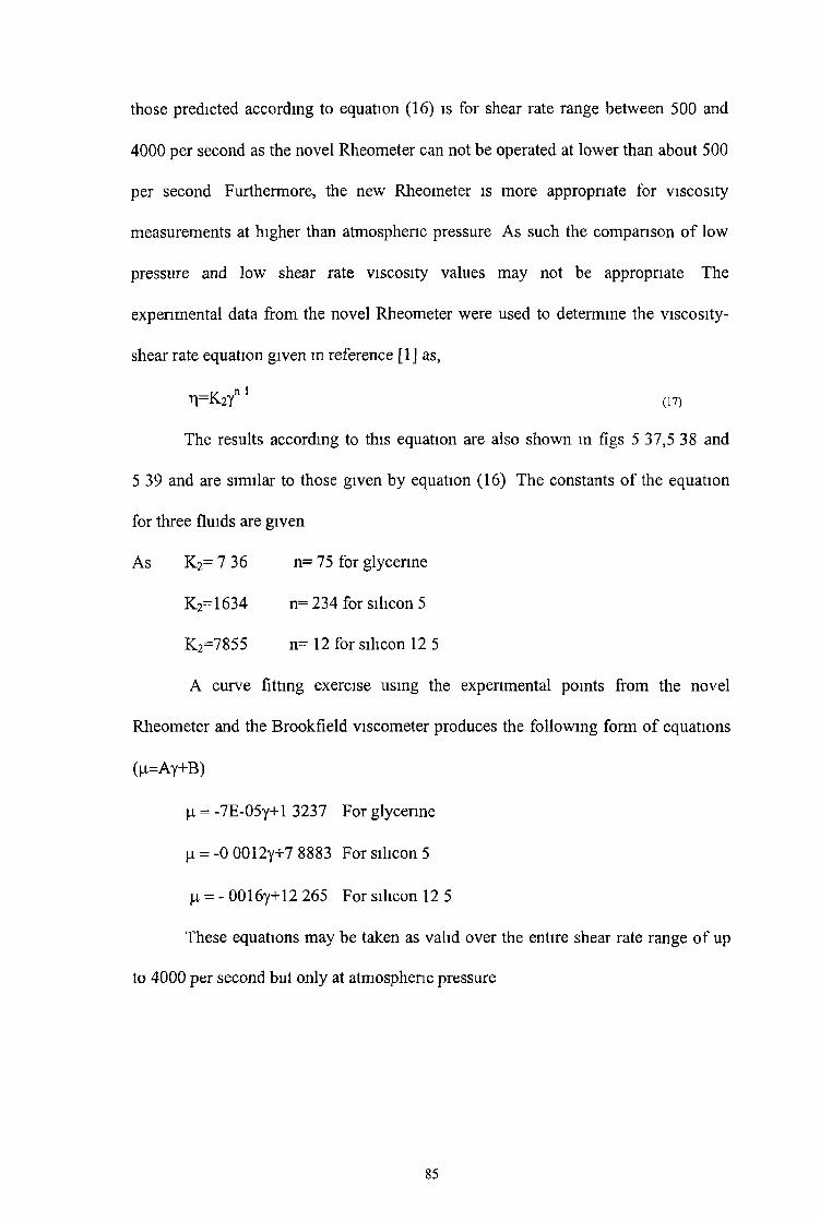
those predicted according to equation (16) is for shear rate range between 500 and
4000 per second as the novel Rheometer can not be operated at lower than about 500
per second Furthermore, the new Rheometer is more appropriate for viscosity
measurements at higher than atmospheric pressure A s such the comparison o f low
pressure and low shear rate viscosity values may not be appropnate The
experimental data from the novel Rheometer were used to determine the viscosity-
shear rate equation given m reference [1] as,
r|=K2yn 1 (17)
The results according to this equation are also shown m figs 5 37,5 38 and
5 39 and are sim ilar to those given by equation (16) The constants o f the equation
for three fluids are given
A s K 2= 7 36 n= 75 for glycenne
K 2=1634 n= 234 for silicon 5
K 2=7855 n= 12 for silicon 12 5
A curve fitting exercise using the expenmental points from the novel
Rheometer and the Brookfield viscometer produces the follow ing form o f equations
(|o.=Ay+B)
(j, = -7E-05y+l 3237 For glycerine
\x = -0 0012y+7 8883 For silicon 5
jj, = - 0016y+12 265 For silicon 12 5
These equations may be taken as valid over the entire shear rate range o f up
to 4000 per second but only at atmospheric pressure
85

1 5
03n
vs
oX.3<f> </) a>
D is t a n c e ,m m
F i g 5 . 1 : P r e s s u r e d i s t r i b u t i o n o f g l y c e r i n e f o r d i f f e r e n t v e l o c i t i e s a t
t h e g a p r a t i o o f 3 .

0 1 0 2 0 3 0 4 0 5 0D ista n ce ,m m
F i g 5 . 2 : P r e s s u r e d i s t r i b u t i o n o f g l y c e r i n e f o r d i f f e r e n t v e l o c i t i e s a t t h e
g a p r a t i o o f 5 .

61 V =0 5m/sec
2 V=1 Om/sec
3 V=1 5m/sec
Transducer! Step
(0-Q0)
-A
(0t/>a>
o
-
0 1 0 2 0 3 0D is t a n c e ,m m
4 0
T ra n sd u c e r
\\
5 0
F i g 5 . 3 : P r e s s u r e d i s t r i b u t i o n o f g l y c e r i n e f o r d i f f e r e n t
s p e e d s a t t h e g a p r a t i o o f 8 .

5
CO-Q
2
" 2 5cn ° a>
o
1 G R = 3
2 G R = 5
3 G R = 8
0 1 0
T r a n s d u c e r ! Step
*,\t, \
\
Transducer2
\ \
\ '
2 0 _ 3 0D is t a n c e ,m m
4 0
F i g 5 . 4 : P r e s s u r e d i s t r i b u t i o n o f g l y c e r i n e a t t h e v e l o c i t y o f
0 . 5 m / s e c f o r d i f f e r e n t g a p r a t i o s .
5 0

Pre
ss
ure
,ba
r
0 1 0 2 0 3 0 4 0 5 0D is t a n c e , m m
F i g 5 . 5 : P r e s s u r e d i s t r i b u t i o n o f g l y c e r i n e a t t h e v e l o c i t y o f
1 . 0 m / s e c f o r d i f f e r e n t g a p r a t i o s

£2OUm3(/)(/>O
0 1 0D i« it a n r í» m m ^ D i s t a n c e , m m
4 0 5 0
F i g 5 . 6 : P r e s s u r e d i s t r i b u t i o n o f g l y c e r i n e a t t h e s p e e d o f 1 . 5 m / s e c
f o r d i f f e r e n t g a p r a t i o s

0 1 0 2 0 3 0 4 0 5 0
D i s t a n c e , m m
F i g 5 . 7 : P r e s s u r e d i s t r i b u t i o n o f s i l i c o n 5 f o r d i f f e r e n t v e l o c i t i e s a t
t h e g a p r a t i o o f 3 .

Pr
es
su
re
,ba
r
0 1 0 2 0 3 0 4 0 5 0
D i s t a n c e , m m
F i g 5 . 8 : P r e s s u r e d i s t r i b u t i o n o f s i l i c o n 5 f o r d i f f e r e n t s h e a r i n g
s p e e d s a t t h e g a p r a t i o o f 3 .

Pre
ss
ure
,ba
r
D i s t a n c e , m m
F i g 5 . 9 : P r e s s u r e d i s t r i b u t i o n o f s i l i c o n 5 f o r t h e d i f f e r e n t s h e a r i n g
s p e e d s a t t h e g a p r a t i o o f 5 .

Pre
ss
ure
,ba
r4 0
3 0
1 V =0 5m/sec
2 V=1 Om/sec
3 V =2 Om/sec
Transducer!Step Transducer2
2 0
1 0
0
' \
0 10 2 0 3 0
D is t a n c e , m m
4 0 5 0
F i g 5 . 1 0 : P r e s s u r e d i s t r i b u t i o n o f s i l i c o n 5 f o r t h e d i f f e r e n t s h e a r i n g
s p e e d s a t t h e g a p r a t i o o f 5 .

Pre
ss
ure
,ba
r
0 1 0 2 0 3 0 4 0 5 0
D i s t a n c e , m m
jF i g 5 . 1 1 : P r e s s u r e d i s t r i b u t i o n o f s i l i c o n 5 f o r d i f f e r e n t s h e a r i n g
s p e e d s a t t h e g a p r a t i o o f 8 .

Pre
ssu
re,b
ar
D is t a n c e ,m mF i g 5 . 1 2 : P r e s s u r e d i s t r i b u t i o n o f s i l i c o n 5 f o r d i f f e r e n t v e l o c i t i e s a t t h e
g a p r a t i o o f 8 .

0 1 0 2 0 3 0 4 0 5 0D i s t a n c e , m m
F i g 5 . 1 3 : P r e s s u r e d i s t r i b u t i o n o f s i l i c o n 5 a t t h e v e l o c i t y
o f 0 . 2 5 m / s e c f o r d i f f e r e n t g a p r a t i o s .
I

0 1 0 2 0 3 0 4 0 5 0D istance,m m
F i g 5 . 1 4 - P r e s s u r e d i s t r i b u t i o n o f s i l i c o n 5 a t t h e v e l o c i t y o f 2 m / s e c f o r
d i f f e r e n t g a p r a t i o s .

/
CDJQ
VS
oL .3CO</>o
D i s t a n c e , m m
F i g 5 . 1 5 : P r e s s u r e d i s t r i b u t i o n o f s i l i c o n 1 2 . 5 f o r d i f f e r e n t v e l o c i t i e s a t t h e g a p r a t i o o f 3.

7 5
(0
23(0W
1 V = 0 5m/sec
6 0 2 V=1 Om/sec
3 V = 2 Om/sec
4 5
3 0 -
1 5 -
0 -
0 1 0
Transducer! Step Tran sd ucer
A
\i\
\
' ' .
\ \ \
' ' j \
4 0 5 02 0 3 0
D i s t a n c e , m m
F i g 5 . 1 6 : P r e s s u r e d i s t r i b u t i o n o f s i l i c o n 1 2 . 5 f o r d i f f e r e n t v e l o c i t i e s a t t h e g a p r a t i o o f 5.

(0-Q
■>
o
U)</>0 )
C L
0 1 0 2 0 3 0
D i s t a n c e , m m
4 0 5 0
F i g 5 . 1 7 : P r e s s u r e d i s t r i b u t i o n o f s i l i c o n 1 2 . 5 f o r t h e d i f f e r e n t v e l o c i t i e s a t t h e g a p r a t i o o f 8

Pr
es
su
re
,ba
r
D i s t a n c e , m m
F i g 5 . 1 8 : P r e s s u r e d i s t r i b u t i o n o f s i l i c o n 1 2 . 5 a t t h e v e l o c i t y O f 0 . 5 m / s e c
f o r d i f f e r e n t g a p r a t i o s

7 5
6 0
(0
5 4 5
</>
2 3 0o .
1 5
0
1 G R = 5
2 GR=3
3 G R =8
Transducer!Step
2
3 \
0 1 0 2 0 3 0
D is t a n c e , m m
4 0
Transducer2
\%\
\ \
i
5 0
F i g 5 . 1 9 : P r e s s u r e d i s t r b u t i o n o f s i l i c o n 1 2 . 5 a t t h e v e l o c i t y o f
2 . 0 m / s e c f o r t h e d i f f e r e n t g a p r a t i o s .

6 0
CO■Q0)L.3COCO<D
4 0
2 0
0
1 G ly c e n n e
2 S ilic o n e 5
3. S ilic o n e 12 5
0 1 0
Transducer!Step
Transducer2
\
2 0 3 0D i s t a n c e , m m
4 0 5 0
F i g 5 . 2 0 : C o m p a r i s o n o f P r e s s u r e d i s t r i b u t i o n o f
g l y c e r i n e , s i l i c o n 5 , s i l i c o n 1 2 . 5 a t t h e g a p r a t i o o f 5 a n d a t
t h e v e l o c i t y o f 1 . 0 m / s e c

0 0 . 5 1 1 . 5 2V e lo c ity ,m /se c
F i g 5 .2 1 : M a x im u m p r e s s u r e v s s p e e d o f
g ly c e r in e f o r d i f f e r e n t g a p r a t io s .

Pre
ss
ure
,ba
r
V e l o c i t y , m / s e c
F i g 5 . 2 2 : M a x i m u m p r e s s u r e v s s p e e d o f s i l i c o n 5 f o r d i f f e r e n t
g a p r a t i o s .

Pre
ss
ure
,ba
r
0 0 5 1 1 5 2 2 5
V e l o c i t y , m / s e c
F i g 5 . 2 3 : M a x i m u m p r e s s u r e v s s p e e d o f s i l i c o n 1 2 . 5 f o r d i f f e r e n t
g a p r a t i o s .
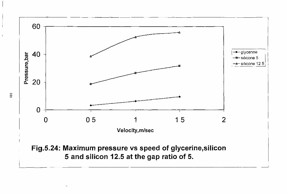
6 0
0 i i i
0 0 5 1 1 5 2
V e l o c i t y , m / s e c
F i g . 5 . 2 4 : M a x i m u m p r e s s u r e v s s p e e d o f g l y c e r i n e , s i l i c o n
5 a n d s i l i c o n 1 2 . 5 a t t h e g a p r a t i o o f 5 .
—♦—glycerine -® -silico n e 5 —a- silicone 12 5

Pre
ssu
re,b
ar1 5
0 1 0 2 0 3 0 4 0 5 0
D is ta n c e fm m
F i g 5 . 2 5 : E x p e r i m e n t a l a n d t h e o r a t i c a l p r e s s u r e p r o f i l e o f
g l y c e r i n e f o r t h e d i f f e r e n t v a l u e s o f ' a ' a n d ' b ' a t t h e v e l o c i t y o f
1 5 m / s e c

D ista n ce ,m m
F i g 5 , 2 6 : E x p e r i m e n t a l a n d t h e o r a t i c a l p r e s s u r e p r o f i l e s o f g l y c e r i n e f o r
t h e d i f f e r e n t v a l u e s o f 'a ' a t t h e v e l o c i t y o f 1 . 5 m / s e c .
— a=150N/mA2
—a— a=500N/mA2
—*-a=600N/m A2
— Experimental

(0-Q
0 1 0 2 0 3 0D ista n ce ,m m
4 0 5 0
F i g 5 . 2 7 : E x p e r i m e n t a l a n d t h e o r a t i c a l p r e s s u r e p r o f i l e o f s i l i c o n 5 w i t h
d i f f e r e n t v a l u e s o f ' a ' a n d ' b ' .

0 1 0 2 0 3 0 4 0 5 0D ista n ce ,m m
F i g 5 . 2 8 : E x p e r i m e n t a l a n d t h e o r a t i c a l p r e s s u r e p r o f i l e o f s i l i c o n 5 f o r t h e
d i f f e r e n t v a l u e s o f 'a ' a t t h e v e l o c i t y o f 1 O m / s e c .

D is t a n c e .m m
F i g 5 . 2 9 : E x p e r i m e n t a l a n d t h e o r a t i c a l p r e s s u r e p r o f i l e o f s i l i c o n 1 2 . 5 f o r
d i f f e r e e n t v a l u e s o f 'a ' a n d 'b ' a t t h e v e l o c i t y o f 1 . 0 m / s e c .

Pre
ssu
re,
ba
r8 0
0 1 0 2 0 3 0 4 0 5 0
D is t a n c e , m m
F i g 5 . 3 0 : E x p e r i m e n t a l a n d t h e o r a t i c a l p r e s s u r e p r o f i l e o f
s i l i c o n 1 2 . 5 w i t h d i f f e r e n t v a l u e s o f ' a ' .

CM<
Eo<D</)
■
Z
> »
COOo</)
0 2 0 4 0 6 0 8 0 1 0 0
P r e s s u r e , b a r
F i g 5 . 3 1 : E f f e c t o f p r e s s u r e o n v i s c o s i t y f o r g l y c e r i n e


Vis
co
sit
y,N
.se
c/
mA
2
P r e s s u r e , b a r
F i g 5 . 3 3 : E f f e c t o f p r e s s u r e o n v i s c o s i t y f o r s i l i c o n 1 2 5


Sh
ea
r st
ress
,N/m
A2
0 1 0 2 0 3 0 4 0
S h e a r r a t e , 1 / s e c
F i g 5 . 3 5 : S h e a r r a t e v s S h e a r s t r e s s o f g l y c e r i n e , s i l i c o n 5 , s i l i c o n 1 2 . 5
u s i n g B r o o k f i e l d v i s c o m e t e r .

1 5
<EooV)
1 0
00 1 0 2 0
S h e a r rate, 1/sec
3 0
g ly c e r in e
s i l i c o n 1 2 5
s i l i c o n 5
4 0
F i g 5 . 3 6 : E f f e c t o f s h e a r r a t e o n v i s c o s i t y o f g l y c e r i n e , s i l i c o n 5 ,
s i l i c o n 1 2 . 5 u s i n g t h e B r o o k f i e l d v i s c o m e t e r .

Vis
co
sit
y,N
.se
c/
m
A2
5
\ 1\\\I\\\
\ \
2 \ \\ \
Ï ------------
M------------ Experimental range for -New Rheometer
H = -7E-05y+l 3237
1■1
0 500 1000 1500 2000 2500 3000
S h e a r r a t e , 1 / s e c
F i g 5 . 3 7 : E f f e c t o f s h e a r r a t e o n v i s c o s i t y o f g l y c e r i n e a t
* a t m o s p h e r i c p r e s s u r e .
— 1 using equation 16
— 2 using equation 17
□ Exptl (BDV+New Rheometer)

Vis
co
sit
y,N
.se
c/
mA
2 1.using equation 16
2.using equation 17
o Exptl.(BDV+New Rheometer)
S h e a r r a t e , 1 / s e c
F i g 5 . 3 8 : E f f e c t o f s h e a r r a t e o n v i s c o s i t y o f s i l i c o n 5 a t
a t m o s p h e r i c p r e s s u r e .

Vis
co
sit
y,N
.se
c/
mA
2 1.using equation 16
2.using equation 17
□ Exptl.(BDV+New Rheometer)
a t m o s p h e r i c p r e s s u r e .
S h e a r r a t e , 1 / s e c
F i g 5 . 3 9 : E f f e c t o f s h e a r r a t e o n v i s c o s i t y o f s i l i c o n 1 2 . 5 a t

5 6 Discussion
5 61 Introduction
Hydrodynam ic principle has been introduced in a novel rheometnc device to
study the rheological behaviour o f non-Newtonian fluids using glycerine and silicon
as examples To investigate the performance o f the device, an extensive experimental
and theoretical programme was conducted during which a considerable amount o f
data were obtained Lim ited expenments were also done by using a Brookfield
viscometer at atmospheric pressure only Th is section is aimed to highlight the
important results obtained experimentally and theoretically to determine the
viscosity-shear rate relationship for glycerine, silicon 5 and silicon 12 5 fluids
The discussion chapter is divided into three sections (i) test procedure and
experimental work (11) analysis and theoretical results and (in ) error analysis
5 6 2 Discussion on Test Procedure and Experimental Work
A number o f interesting results have been observed while carrying out the
experimental tests, using the new rheometnc device and glycerine and silicon as the
test fluids During the course o f the experimental programme, parameters such as gap
ratios, shearing speed, fluid type were varied in order to investigate their effect on
the performance o f the pressure unit The length and the length ratio, the outlet gap
h2 were constant throughout the tests Experimental work was first done with the two
pressure transducers, their rating was 2000 bar using glycerine as the test fluid The
readings were not changing with the change o f the speed The pressure transducers
125

were over rated and hence new lower capacity 70 bar ones were selected These new
transducers were found to be sensitive to the variation o f pressure with changing
shear velocity
The results o f the pressure versus shearing speed using silicon 5, silicon 12 5
and glycerine as test fluids are shown m F ig 5 1 to 5 20 For the gap ratio o f 5 the
generated pressure is found to be higher A s the inlet gap decreases, the fluid flow
rate also decreases into the gap, which m turn is thought to be responsible for lower
pressure A n increase m the inlet gap without increasing the outlet gap may cause
back flow o f the polymer which would also reduce the pressure From F ig 5 35 it is
seen that glycerine and silicon 5 show Newtonian behaviour as the shear stress and
shear rate curves are almost linear for shear rate values o f less than about 30 per
second Silico n 12 5 shows non-Newtonm behaviour Th is is also confirmed from the
results in F igs 36 F igs 5 37 to 5 39 show the viscosity vs shear rate curves A t lower
shear rate the predicted viscosity values are much higher than those measured using
the Brookfield viscometer The difference m results is due to the fact that
experimental work was earned using the new rheometer at higher shear rates and the
coefficients were calculated according to theoretical and expenmental results at
higher shear rate The thermocouple was connected where the pressure reading is
zero, so that the actual temperature cannot be measured W ith an increase o f one
degree centigrade at that location the temperature in the may increase by several
degrees which may decrease the viscosity and hence the pressure readings
126

A model has been developed based on the assumption that the pressure
medium demonstrates non-Newtoman characteristics The follow ing assumptions
were made m order to sim plify the analysis
(I) The flow o f the fluid medium m the present pressure unit is laminar Th is
seems to be a reasonable assumption since the shearing speeds o f the shaft are
relatively low and the gaps are small
(II) The flow o f the fluid pressure medium is axial Once flow through the
pressure unit has commenced, little or no back flow is expected Th is
assumption allowed one-dimensional flow to be considered
(III) The thickness o f the fluid layer is sm all compared to the dimensions o f the
Rheometnc pressure unit Th is assumption enabled the analysis to be
conducted in cartesians rather than cylindrical co-ordinates
(iv) The pressure m the fluid medium is uniform m the thickness direction This
assumption sim plified calculation o f the pressure m the unit and allowed the
viscosity constant to be evaluated
(v) The flow o f the fluid through the unit is isothermal Th is may introduce some
error in the results since viscosity o f the fluids is sensitive to the temperature
change
The empencal non-Newtoman equation commonly used to represent the behaviour
o f the fluid, as proposed by Rabinowitch [12] takes the form,
I + K t3 = \x — dy
Th is equation was used in the analysis to predict the pressure The non-Newtoman
factor 'K ' and the in itial viscosity |i were both determined experimentally by curve
5 6 3 Discussion on the Analysis and the Theoretical Results
127

f i t t i n g t h e a b o v e e q u a t i o n o v e r t h e r e s u l t s o b t a i n e d f r o m t h e f l o w c h a r a c t e r i s t i c s o f
p o l y m e r m e l t
T h e a b o v e e q u a t i o n r e p r e s e n t s t h e e f f e c t o f s h e a r s t r e s s o n t h e v i s c o s i t y o n l y
I t i s k n o w n t h a t t h e p r e s s u r e i n c r e a s e s t h e v i s c o s i t y o f t h e f l u i d T o i n c o r p o r a t e t h i s
e f f e c t m t h e a n a l y s i s , t h e d a t a p r o v i d e d b y W e s t o v e r f o r t h e A l k a t h e n e p o l y m e r w a s
u s e d t o p r o d u c e F i g 1 2 W h i c h s h o w s t h a t t h e i n f l u e n c e o f p r e s s u r e o n t h e v i s c o s i t y
i s d e p e n d e n t o n t h e s h e a r r a t e T h e a c c u r a c y o f W e s t o v e r ' s r e s u l t s i s n o t k n o w n a n d
u n f o r t u n a t e l y t h e p o l y m e r u s e d f o r h i s e x p e r i m e n t s w a s n o t W V G 2 3 T h e r e f o r e t h i s
m a y h a v e i n t r o d u c e d s o m e d i s c r e p a n c y m t h e t h e o r e t i c a l r e s u l t s i n F i g l 2 , A
g e n e r a l i s e d e q u a t i o n w a s d e r i v e d t o p r e d i c t t h e v i s c o s i t y o f t h e p o l y m e r m e l t a t
k n o w n p r e s s u r e a n d t h e s h e a r r a t e s w h i c h i s s h o w n t o t a k e t h e f o r m
a + bp2 M = —
r
vw h e r e y i s t h e a p p a r e n t s h e a r r a t e m t h e f i r s t p a r t o f t h e u n i t a n d a s s u m e d t o b e — ,
K
T h e t h e o r e t i c a l v a l u e o f juQ a n d n o n - N e w t o n i a n f a c t o r ’K 1 h a v e b e e n t a k e n f r o m
r e f [ 4 9 ] i n w h i c h s i m i l a r f l u i d s w e r e u s e d H o w e v e r , t h e r e w e r e s o m e d i f f e r e n c e s i n
t h e p r o p e r t i e s , w h i c h m a y p r o d u c e s o m e e r r o r i n t h e t h e o r e t i c a l r e s u l t s
5 6 4 Error Analysis
E r r o r s a l w a y s o c c u r i n e x p e r i m e n t a l w o r k o w i n g t o i n a c c u r a c i e s o f o t h e r
v a r i a b l e s , h o w e v e r s m a l l t h e y m a y b e , w h i c h t h e f i n a l r e s u l t s d e p e n d u p o n
I n v e s t i g a t i o n o f t h e p r o b a b l e e r r o r i s t h e r e f o r e n e c e s s a r y b e f o r e r e s u l t s c a n b e
c o n s i d e r e d w i t h s o m e d e g r e e o f c o n f i d e n c e T h e o r e t i c a l r e s u l t s w e r e p r e d i c t e d u s i n g
128

n u m e n c a l t e c h n i q u e s i n c o r p o r a t i n g i n t e r a t i o n m e t h o d s I n c o n j u n c t i o n t o t h e
e x p e r i m e n t a l a n d t h e o r e t i c a l r e s u l t s , t h e v a l u e s o f t h e p r e s s u r e c o e f f i c i e n t s o f
v i s c o s i t y h a v e b e e n d e t e r m i n e d u s i n g a n i t e r a t i o n t e c h n i q u e F o r d i f f e r e n t v a l u e s o f
' a ' a n d ' b ' d i f f e r e n t t h e o r e t i c a l p r e s s u r e v a l u e s h a v e b e e n o b t a i n e d a t t h e s a m e
s h e a r i n g s p e e d E r r o r h a s b e e n c a l c u l a t e d w i t h m t h e d i f f e r e n c e b e t w e e n t h e
t h e o r e t i c a l a n d t h e e x p e r i m e n t a l p r e s s u r e v a l u e s A p p e n d i x C s h o w s t h e e r r o r
a n a l y s i s f o r d i f f e r e n t t y p e s o f f l u i d F o r g l y c e r i n e ( a = 3 0 0 N / m 2 , b = 4 x 1 0 1 1 m 2 / N )
a t t h e g a p r a t i o o f 8 , 5 a n d 3 a t t h e s p e e d o f 0 5 m / s e c t h e p e r c e n t a g e o f e r r o r s a r e
1 2 , 1 4 a n d 1 1 8 r e s p e c t i v e l y O n t h e o t h e r h a n d f o r t h e s a m e f l u i d f o r t h e s a m e v a l u e
o f ' a ' a n d fb f a t t h e g a p r a t i o o f 8 , 5 a n d 3 a t t h e s p e e d o f 1 5 m / s e c , t h e p e r c e n t a g e o f
e r r o r s a r e 7 , 5 , 5 a n d 2 4 A p o s s i b l e a r i t h m e t i c e r r o r o f a b o u t ± 1 5 % w e r e o c c u r r e d
i n t h e t h e o r e t i c a l a n d e x p e r i m e n t a l p r e s s u r e v a l u e s w h i l e c a l c u l a t i n g t h e v a l u e s o f t h e
p r e s s u r e c o e f f i c i e n t s o f v i s c o s i t y A c o n s i d e r a b l e d i f f e r e n c e h a s b e e n o b s e r v e d
b e t w e e n s o m e o f t h e e x p e n m e n t a l a n d t h e t h e o r e t i c a l r e s u l t s , b a s e d o n m e a n v a l u e s
o f ‘ a ’ a n d c b ’ o f e q u a t i o n ( 1 6 ) T h i s s u g g e s t s t h a t t h e a n a l y s i s e a r n e d o u t f o r t h e
r h e o m e t n c d e v i c e n e e d s m o r e r e f i n e m e n t I t i s b e l i e v e d t h a t t h e d i s c r e p a n c i e s m a y
h a v e a n s e n d u e t o t h e v a l u e o f n o n - N e w t o n i a n f a c t o r ' K ' , t h e a b s e n c e o f t h e
p a r a m e t e r i n t h e a n a l y s i s w h i c h a f f e c t t h e f l o w p r o p e r t i e s o f f l u i d s
129

C h a p t e r S ix
C O N C L U S I O N A N D S U G G E S S I O N S F O R
F U R T H E R W O R K
T h i s c h a p t e r p r e s e n t s a s u m m e r y o f t h e c u r r e n t t h e s i s I t i s d i v i d e d i n t o t w o
s e c t i o n s T h e f i r s t s e c t i o n r e p r e s e n t s t h e i n v e s t i g a t i o n u n d e r c o n s i d e r a t i o n , t h e
t e c h n i q u e s t o c a r r y o u t t h i s t a s k a n d a b r i e f s u m m e r y o f t h e c o n c l u s i o n , a n d t h e
s e c o n d i d e n t i f i e s f u r t h e r s t u d i e s t h a t c a n b e p u r s u d e i n f u t u r e w o r k s
6 2 Conclusion
T h i s t h e s i s o u t l i n e s t h e a u t h o r ' s r e s e a r c h e f f o r t m t h e a r e a o f h i g h - p r e s s u r e
n o n - N e w t o n i a n f l u i d r h e o l o g y
• T h i s w o r k i n v o l v e d m e a s u r e m e n t o f t h e v a r i a t i o n o f p r e s s u r e w i t h s h e a r
r a t e a n d g a p r a t i o f o r g l y c e r i n e a n d s i l i c o n u s i n g a n o v e l r h e o m e t e r
d e s i g n e d o n t h e b a s i s o f h y d r o d y n a m i c p r i n c i p l e s T h e r a n g e o f s h e a r r a t e
i s 5 0 0 t o 4 0 0 0 p e r s e c o n d
• A t h e o r e t i c a l a n a l y s i s b a s e d o n t h e n o n - N e w t o n i a n c h a r a c t e r i s t i c s f o r a
n e w r h e o m e t n c d e v i c e h a s b e e n p r e s e n t e d w h e r e t h e e f f e c t o f t h e
h y d r o d y n a m i c p r e s s u r e i n f l u e n c e s t h e v i s c o s i t y o f t h e f l u i d s
• T h e i n f l u e n c e o f t h e g e o m e t r y o f t h e u n i t a n d t h e s p e e d o n t h e m a x i m u m
p r e s s u r e g e n e r a t i o n , w h i c h a f f e c t t h e v i s c o s i t y , h a s a l s o b e e n d i s c u s s e d
E x p e r i m e n t a l r e s u l t s f r o m t h e p r e s s u r e d i s t r i b u t i o n w i t h i n t h e s t e p p e d
61 Introduction
130
p a r a l l e l g a p R h e o m e t n c d e v i c e h a v e b e e n u s e d m c o n j u n c t i o n w i t h t h e
t h e o r e t i c a l p r e s s u r e r e s u l t s t o d e t e r m i n e t h e c o e f f i c i e n t s f o r a v i s c o s i t y
s h e a r r a t e
• U s i n g t h e s e c o e f f i c i e n t s , t h e v i s c o s i t y a t d i f f e r e n t p r e s s u r e s w a s c a l c u l a t e d
a n d t h e e f f e c t o f s h e a r r a t e a n d p r e s s u r e o n v i s c o s i t y w a s d e m o n s t r a t e d
• U s i n g t h e c o e f f i c i e n t s t h e v i s c o s i t y o f t h e s e f l u i d s w a s p r e d i c t e d a t l o w e r
s h e a r r a t e s a t a t m o s p h e n c p r e s s u r e U s i n g t h e B r o o k f i e l d v i s c o m e t e r ,
v i s c o s i t y v a l u e s o f t h e t h r e e d i f f e r e n t t y p e s o f f l u i d s w e r e m e a s u r e d a t
d i f f e r e n t l o w e r s p e e d s a n d t h e s h e a r r a t e v s v i s c o s i t y c u r v e h a s b e e n
p l o t t e d T h e s e v a l u e s w e r e m u c h h i g h e r t h a n t h o s e m e a s u r e d u s i n g t h e
B r o o k f i e l d v i s c o m e t e r
• N e w t y p e o f e q u a t i o n s h a v e b e e n d e v e l o p e d a t t h e s h e a r r a n g e 0 t o
4 0 0 0 S e c 1 b a s e d o n t h e e x p e r i m e n t a l r e s u l t s u s i n g t h e B D V a n d N e w
R h e o m e t e r
• T h e n e w R h e o m e t n c d e v i c e i s a n i n n o v a t i v e f a c i l i t y m h i g h - p r e s s u r e f l u i d
r h e o l o g y
A l t h o u g h c o n s i d e r a b l e a m o u n t o f w o r k o n t h e p r o c e s s w a s d o n e s o f a r , t h e r e
a r e m o r e a v e n u e s o f w o r k o n t h i s p r o c e s s m t h e f u t u r e
6 3 Suggessions For Future Work
• I n t h e p r e s e n t w o r k t h e a n a l y s i s w a s d e v e l o p e d a s s u m i n g i s o t h e r m a l
c o n d i t i o n I t i s s u g g e s t e d t h a t a g r e a t d e a l o f k n o w l e d g e c o u l d b e o b t a i n e d
a b o u t t h e r h e o l o g y o f d i f f e r e n t n o n - N e w t o n i a n f l u i d s a t e l e v a t e d
t e m p e r a t u r e s
131

• T h e v i s c o s i t y o f a f l u i d i s k n o w n t o b e s e n s i t i v e t o t h e t e m p e r a t u r e
c h a n g e , h e n c e a r e l a t i o n s h i p p r e d i c t i n g t h e v i s c o s i t y c h a n g e d u e t o t h e
t e m p e r a t u r e v a r i a t i o n m a y i m p r o v e t h e r e s u l t s
• T h e r h e o l o g y o f t h e f l u i d s h o u l d b e b e t t e r u n d e r s t o o d w i t h r e s p e c t t o t h e
e f f e c t o f p r e s s u r e a n d t e m p e r a t u r e o n v i s c o s i t y S o , t h e t h e o r e t i c a l m o d e l
s h o u l d b e b a s e d o n b o t h t h e t e m p e r a t u r e a n d p r e s s u r e
• I n t h e p r e s e n t s t u d y t h e t e m p e r a t u r e o f t h e f l u i d w a s m o n i t o r e d o u t s i d e
t h e p r e s s u n e d g a p w h e r e t h e h y d r o d y n a m i c p r e s s u r e i s z e r o T h e
t e m p e r a t u r e s h o u l d b e m e a s u r e d w i t h m t h e g a p B u t i t i s d i f f i c u l t t o i n s e r t
a t h e r m o c o u p l e m t h e s t e p w i t h o u t d a m a g i n g t h e s t e p c o n f i g u r a t i o n S o ,
f i n i t e e l e m e n t m o d e l l i n g c a n b e u s e d f o r p r e d i c t i n g t h e t h e o r e t i c a l
t e m p e r a t u r e m t h e s t e p
• T h e g e o m e t r y o f t h e p r e s s u r e u n i t c o u l d b e c h a n g e d t o t a p e r e d , c o m b i n e d
o r p a r a b o l i c t y p e s
• T h e p r e s s u r e t r a n s d u c e r s c o u l d b e p l a c e d a t t h e n e a r e s t p o s i t i o n o f t h e
s t e p
• T h e e x p e r i m e n t a l w o r k c o u l d b e d o n e a t t h e l o w e r s h e a r i n g s p e e d s
m o d i f y i n g t h e t h i c k n e s s o f t h e e n t r y g a p o f t h e u n i t a n d a t t h e l o w e r s h e a r
r a t e , t h e c o e f f i c i e n t v a l u e s c a n b e o b t a i n e d
132

REFERENCES
[ 1 ] H A B a r n e s , J F H u t t o n a n d K W a l t e r , “ A n I n t r o d u c t i o n t o R h e o l o g y ” , p u b l i s h e d
b y E l s e v i e r S c i e n c e , N e t h e r l a n d s , 1 9 8 0
[ 2 ] C a r l e y , J F “ J M o d e m P l a s t i c s ” , D e c e m b e r , 1 9 6 1
[ 3 ] N i e l s e n , L E “ P o l y m e r R h e o l o g y ” , N e w Y o r k , 1 9 7 7
[ 4 ] S a n c h e z , I C “ J A p p l P h y s ” , p p 4 5 & 4 2 0 4 , 1 9 7 4
[ 5 ] W e s t o v e r , R F “ P o l y m e r E n g g S e i ” , p p 6 & 8 3 , 1 9 6 6
[ 6 ] C o h e n , M a n d T u r n b u l l , D “ J C h e m P h y s ” , p p 3 1 & 1 1 6 4 , 1 9 5 9
[ 7 ] J a c o b s o n , B O , R h e o l o g y a n d E l a s t o h y d r o d y n a m i c L u b r i c a t i o n , T r i b o l o g y
S e r i e s , 1 9 , E l s e v i e r S c i e n c e P u b l i s h e r s , I S B N 0 - 4 4 - 8 8 1 4 6 - 8 , 1 9 9 1
[ 8 ] W e s t o v e r R F , “ T h e s i g n i f i c a n c e o f s l i p i n p o l y m e r m e l t f l o w , P o l y m e r
E n g i n e e r i n g a n d S c i e n c e , J a n u a r y , p p 6 , 8 3 - 8 9 , 1 9 6 0
[ 9 ] B M a x w e l l , a n d J u n g , A , “ H y d r o s t a t i c p r e s s u r e e f f e c t o n p o l y m e r m e l t v i s c o s i t y ” ,
M o d e m P l a s t i c s , 3 5 , N o v e m b e r , p p 1 7 4 , 1 9 5 7
[ 1 0 ] C h o i , S Y , “ D e t e r m i n a t i o n o f m e l t v i s c o s i t y a s a f u n c t i o n o f h y d r o s t a t i c p r e s s u r e
i n a n e x t r u s i o n r h e o m e t e r ” , J o u r n a l o f P o l y m e r S c i e n c e , A - 2 , V o l 6 , p p 2 0 4 3
[ 1 1 ] C o g s w e l l , F N , “ T h e i n f l u e n c e o f p r e s s u r e o n t h e v i s c o s i t y o f p o l y m e r m e l t s ” ,
P l a s t i c s a n d p o l y m e r s , F e b r u a r y , p p 3 9 a n d 4 1 , 1 9 7 3
133

[ 1 2 ] R a b i n o w i t s c h , B , “ U b e r D i e V i s k o s t a t a n d E l a s t i z i t ä t V o n S o l e n ” , Z P h y s C h e m
A 1 4 5 , p p 1 4 1 , 1 9 2 9
[ 1 3 ] M L W I L L I A M S , R F L A N D E L a n d J D F E R R Y , “ T h e t e m p e r a t u r e d e p e n d e n c e
o f r e l a x a t i o n m e c h a n i s m s i n a m o r p h o u s p o l y m e r s a n d o t h e r g l a s s - f o r m i n g l i q u i d s ” ,
J o u r n a l o f t h e A m e n c a n C h e m i c a l S o c i e t y , p p 7 7 , 3 7 0 1
[ 1 4 ] J A B R Y D S O N , “ F l o w p r o p e r t i e s o f p o l y m e r m e l t s ” , P u b l i s h e d B y P l a s t i c
I n s t i t u t e , L o n d o n , I l l i f f e B o o k s , 1 9 7 0
[ 1 5 ] D I E N E S , G J A p p l i e d P h y s 2 4 , 7 7 9 , 1 9 5
[ 1 6 ] C r a m p t o n R “ H y d r o d y n a m i c L u b n c a t i o n a n d C o a t i n g o f W i r e u s i n g a P o l y m e r
M e l t D u r i n g D r a w i n g P r o c e s s ” , P h D T h e s i s , S h e f i e l d C i t y P o l y t e c h n i c , 1 9 8 0
[ 1 7 ] E B B A G L E Y , “ T h e s e p a r a t i o n o f e l a s t i c a n d v i s c o u s e f f e c t m p o l y m e r f l o w ” ,
T r a n s O f T h e S o c i e t y o f R h e o l o g y , p p 3 4 1 - 3 5 3 , 1 9 6 1
[ 1 8 ] E R H O W E L L S a n d J J B E N B O W , “ F l o w d e f e c t s m p o l y m e r m e l t s ” , I C I
P u b l i c a t i o n , A u g u s t 1 9 6 2
[ 1 9 ] A B M E T Z N E R , “ F r a c t u r e o f n o n - N e w t o n i a n f l u i d s a t h i g h e r s h e a r s t r e s s e s ” ,
I n d u s t r i a l a n d e n g C h e m i s t r y , V o l 5 0 , N o 1 0 , 1 9 5 8
[ 2 0 ] C h r i s t o p h e r s o n , D G a n d P B N a y l o r , “ P r o m o t i o n o f f l u i d l u b r i c a t i o n m w i r e
d r a w i n g ” , P r o c e e d i n g o f I n s t i t u t e o f M e c h a n i c a l o f E n g i n e e r i n g , , p p 1 6 9
a n d 6 4 3 - 6 5 3 , 1 9 5 5
[ 2 1 ] W i s t r e i c h , J G , “ L u b n c a t i o n m w i r e m g d r a w i n g ” , Wear , M a r c h ( 1 9 9 7 ) , p p 5 0 5 -
5 1 1 , 1 9 9 7
134

[ 2 2 ] T A T T E R S A L L , G H “ H y d r o d y n a m i c L u b r i c a t i o n I n W i r e D r a w i n g ” J M e c h E n g g
S c , V o l 3 , N o 4 , p p 3 7 8 , 1 9 6 1
[ 2 3 ] C H U , P S “ T h e o r y o f l u b r i c a t i o n a p p l i e d t o p r e s s u r e n o z z l e d e s i g n m w i r e d r a w i n g ”
P r o c I n s t M e c h E n g g , V o l 1 8 1 , p p - 3 , 1 9 6 7
[ 2 4 ] B e d i D S “ A h y d r o d y n a m i c m o d e l f o r w i r e d r a w i n g ” T h e i n t e r n a t i o n a l J
p r o d u c t i o n a n d R e s e a r c h , V o l 6 , N o 4 , 1 9 6 8
[ 2 5 ] B l o o r M , D A W S O N D , a n d P A R S O N B , “ A n e l a s t o - p l a s t - h y d r o d y n a m i c
l u b r i c a t i o n a n a l y s i s o f t h e p l a n e s t r a i n d r a w i n g p r o c e s s ” , J - M e c h S c , V o l 1 2 ,
N o 3 , 1 9 7 0
[ 2 6 ] O S T E R L E J F a n d D I X O N J R , “ V i s c o u s l u b n c a a t i o n i n w i r e d r a w i n g ” , A S L E
T r a n s a c t i o n s , v o l 5 , p p 2 3 3 - 2 4 1 , 1 9 6 2
[ 2 7 ] M I D D L E M I S S A , “ H y d r o s t a t i c l u b r i c a t i o n f o r d r a w i n g s t e e l w i r e , ” T n b o l o g y i n
i r o n a n d s t e e l w o r k s , I S I , P u b l i c a t i o n 1 2 5
[ 2 8 ] K A L M O G R O V , V L A N D S E L I S H C H E V , K P “ C o l d d r a w i n g t u b e s w i t h
i m p r o v e d l u b r i c a t i o n ” s t a l l m e n g l i s h p p 8 3 0 - 8 3 1 , 1 9 6 2
[ 2 9 ] O r l o v , S I , K o l m o g r o v , V L , U r a l , S k l l , V I A n d S t u k a l o v , V T , “ I n t r e g a t e d
D e v e l o p m e n t a n d I n t r o d u c t i o n o f N e w H i g h - S p e e d M i l l a n d H y d r o d y n a m i c
L u b r i c a t i o n S y s t e m f o r D r a w i n g W i r e s ” , S t e e l I n T h e U S S R , V o l 1 0 , p p
9 5 3 - 9 5 6 , 1 9 7 4
[ 3 0 ] S w a m y , S T N P r a b h u , B S a n d R a o , B V A “ C a l c u l a t e d L o a d C a p a c i t y o f N o n -
N e w t o n i a n l u b r i c a t i o n m F i n i t e W i d t h B e a r i n g s ” , E A R , V o l 3 ( 1 9 7 5 ) , p p 2 7 7 - 2 8 5
135

[ 3 1 ] T h o m p s o n , P J a n d S y m m o n s , G R , “ A P l a s t o H y d r o d y n a m i c a n a l y s i s o f t h e
L u b r i c a t i o n a n d C o a t i n g u s i n g P o l y m e r M e l t D u r i n g D r a w i n g ” , P r o c I n s t M e c h
E n g V o l 1 9 1 , p p 1 3 , 1 9 7 7
[ 3 2 ] S l e v e n s , A T , “ A p l a s t o - H y d r o d y n a m i c I n v e s t i g a t i o n o f t h e L u b r i c a t i o n a n d
C o a t i n g o f W i r e U s i n g a P o l y m e r M e l t D u r i n g D r a w i n g ” , M P h i l T h e s i s , S h e f i e l d
C i t y P o l y t e c h n i c , 1 9 7 9
[ 3 3 ] C r a m p t o n , R S y m m o n s , G R , a n d H a s h m i , M S J “ A n o n - N e w t o n i a n P l a s t o -
h y d r o d y n a m i c a n a l y s i s o f t h e l u b r i c a t i o n a n d c o a t i n g o f w i r e u s i n g a p o l y m e r m e l t
d u r i n g d r a w i n g ” , I n t S y m p o s i u m , m e t a l w o r k i n g l u b r i c a t i o n , S a n F r a n s i s c o , U S A ,
p p 1 0 7 - 1 1 5 , A u g u s t 1 9 8 0
[ 3 4 ] M I P A N W H E R , R C R A M P T O N A N D M S J H A S H M I “ D i e l e s s t u b e s i n k i n g
p a s t o - h y d r o d y n a m i c a n a l y s i s b a s e d o n N e w t o n i a n f l u i d c h a r a c t e r i s t i c s ”
P r o c e e d i n g s o f 1 s t C o n f e r e n c e o n M a n u f a c t u r i n g t e c h n o l o g y , I n s h M a n u f a c t u r i n g
C o m m i t t e e , p p 1 5 3 - 1 7 2 , D u b l i n , M a r c h 1 9 8 4
[ 3 5 ] M S J H A S H M I , R C R A M P T O N a n d M I P A N W H E R “ P l a s t o - h y d r o d y n a m i c
t u b e s i n k i n g E x p e n m e n t a l e v i d e n c e a n d n u m e r i c a l s o l u t i o n ” P r o c e e d i n g o f 3 r d
I n t e r n a t i o n a l C o n f e r e n c e o n N u m e r i c a l m e t h o d s f o r n o n - l i n e a r p r o b l e m s ,
D u b r o v n i k , Y u g o s l a v i a , S e p t e m b e r , p p 1 1 5 - 1 2 9 , 1 9 8 6
[ 3 6 ] M S J H A S H M I , R C R A M P T O N a n d ] M I P A N W H E R “ M a t h e m a t i c a l m o d e l l i n g
o f d i e l e s s t u b e s i n k i n g b a s e d o n n o n - l i n e a r d e f o r m a t i o n p r o f i l e P r o c e e d i n g o f 6 t h
C o n f e r e n c e o f t h e I n s h M a n u f a c t u r i n g C o m m i t t e e , p p 2 4 8 - 2 5 4 , D u b l i n , A u g u s t
1 9 8 9
[ 3 7 ] M I P A N W H E R “ A n o v e l t e c h n i q u e f o r t u b e s i n k i n g ” P h D T h e s i s S H E F I E L D
C i t y P o l y t e c h n i c , 1 9 8 6
136

[ 3 8 ] M I P A N W H E R , R C R A M P T O N a n d ] M S J H A S H M I , ” A n a l y s i s o f t h e d i e -
l e s s t u b e s i n k i n g p r o c e s s b a s e d o n n o n - N e w t o n i a n c h a r a c t e r i s t i c s o f t h e f l u i d
m e d i u m ” , J o u r n a l o f M a t e r i a l P r o c e s s i n g T e c h n o l o g y , v o i 2 1 , p p 1 5 5 - 1 7 5 , 1 9 9 0
[ 3 9 ] G R S y m m o n s , H a s h m i , M S J a n d Y D X I E , “ T h e o p t i m i s a t i o n o f P l a s t o -
h y d r o d y n a m i c w i r e d r a w i n g p r o c e s s ” , P r o c e e d i n g o f 6 t h I n t e r n a t i o n a l C o n f e r e n c e
o n M o d e l l i n g , P a n s , F r a n c e , J u n e , p p 3 6 2 - 3 6 6 , 1 9 8 7
[ 4 0 ] G R S y m m o n s , Y D X I E a n d H a s h m i , M S J “ T h e r m a l e f f e c t o n a p l a s t o -
h y d r o d y n a m i c w i r e d r a w i n g u s i n g a p o l y m e r m e l t ” P r o c e e d i n g s o f X t h
I n t e r n a t i o n a l C o n f e r e n c e o n R h e o l o g y , V o i 2 , p p 2 9 5 - 2 9 7 , S y d n e y , A u s t r a l i a ,
A u g u s t 1 9 8 8
[ 4 1 ] G R S Y M M O N S , A H M E M O N a n d M S J H A S H M I “ A m a t h e m a t i c a l m o d e l
o f a p l a s t o - h y d r o d y n a m i c d r a w i n g o f n a r r o w s t n p ” M a t h e m a t i c a l c o m p u t a t i o n
m o d e l l i n g , V o i 1 1 p p 9 2 6 - 9 3 1 , 1 9 8 8
[ 4 2 ] G R S Y M M O N S , A H M E M O N a n d M S J H A S H M I , " A N e w t o n i a n m o d e l o f
a p l a s t o - h y d r o d y n a m i c d r a w i n g p r o c e s s o f a r e c t a n g u l a r c r o s s s e c t i o n a l
c o n t i n u u m ” , P r o c e e d i n g o f 7 t h I n t e r n a t i o n a l C o n f e r e n c e o n m o d e l l i n g
i d e n t i f i c a t i o n a n d c o n t r o l , p p 6 7 - 7 0 , G n n d l w a l d , S w i t z e r l a n d , F e b r u a r y 1 9 8 8
[ 4 3 ] G R S Y M M O N S , A H M E M O N , R C R A M P T O N a n d M S J H A S H M I , " A n
e x p e n m e n t a l s t u d y o f a p l a s t o - h y d r o d y n a m i c s t n p d r a w i n g p r o c e s s o f n g i d n o n -
l i n e a r l y s t r a i n h a r d e n i n g s t n p t h r o u g h a s t e p p e d r e c t a n g u l a r s l o t ” , J o u r n a l o f
p r o c e s s m e c h a n i c a l e n g i n e e r i n g , P r o c e e d i n g o f I m e c h E , P a r t E , V o i 2 0 3 , p p 5 7 -
6 5 , 1 9 8 9
[ 4 4 ] G R S Y M M O N S , A H M E M O N , R C R A M P T O N a n d M S J H A S H M I , , r A
n u m e n c a l s o l u t i o n f o r p l a s t o - h y d r o d y n a m i c d r a w i n g o f n g i d n o n - h n e a r l y s t r a i n
137

h a r d e n i n g s t r i p s t h r o u g h a s t e p p e d r e c t a n g u l a r s l o t ” , P r o c e e d i n g o f 3 r d
I n t e r n a t i o n a l C o n f e r e n c e o n N u m e r i c a l m e t h o d s m I d F o r m i n g P r o c e s s , p p 5 7 5 -
5 8 0 , C o l o r a d o , U S A , J u n e , 1 9 8 9
[ 4 5 ] H P a r v m m e h r , G R S y m m o n s , a n d M S J H a s h m i , " A n o n - N e w t o n i a n p l a s t o -
h y d r o d y n a m i c a n a l y s i s o f d i e l e s s w i r e - d r a w i n g p r o c e s s u s i n g a s t e p p e d b o r e u n i t ”
I n t e r n a t i o n a l J o u r n a l o f M e c h a n i c a l S c i e n c e V o l 2 9 n o 4 , p p 5 4 - 6 2 , L o n d o n ,
M a y 1 9 8 2
[ 4 6 ] M S J H a s h m i , G R S y m m o n s , a n d H P a r v m m e h r , ” A n o v e l t e c h n i q u e o f w i r e
d r a w i n g ” , J o u r n a l o f M e c h a n i c a l E n g i n e e r i n g S c i , I n s t M e c h N e g r o 2 4 , 1 9 8 2
[ 4 7 ] G R S y m m o n s , M S J H a s h m i a n d H P a r v m m e h r ” P l a s t o - h y d r o d y n a m i c d i e l e s s
w i r e d r a w i n g t h e o r a t i c a l t r e a t m e n t a n d e x p e r i m e n t a l r e s u l t s , ” P r o c e e d i n g s o f
I n t e m t i o n a l C o n f e r e n c e o n D e v e l o p m e n t m D r a w i n g M e t a l s , M e t a l s S o c e i t y , p p
5 4 - 6 2 , L o n d o n , M a y 1 9 8 3
[ 4 8 ] G R S y m m o n s , M S J H a s h m i a n d H P a r v m m e h r “ A s p e c t s o f p r o d u c t q u a l i t y
a n d p r o c e s s c o n t r o l m p l a s t o - h y d r o d y n a m i c d i e l e s s w i r e d r a w i n g ” , P r o c e e d i n g o f
1 s t C o n f e r e n c e o n M a n u f a c t u r i n g t e c h n o l o g y , I r i s h M a n u f a c t u r i n g C o m m i t t e e ,
p p 1 5 3 - 1 7 2 , D u b l i n , M a r c h 1 9 8 4
[ 4 9 ] H p a r v m m e h r , “ O p t i m i s a t i o n o f p l a s t o - h y d r o d y n a m i c s y s t e m o f w i r e d r a w i n g
u s i n g p o l y m e r m e l t s ” , P h D T h e s i s , S h i e f i e l d C i t y P o l y t e c h n i c , U K , ( 1 9 8 3 )
[ 5 0 ] H A S H M I M S J a n d S Y M M O N S G R “ A n u m e n c a l s o l u t i o n f o r t h e
p l a s t o h y d r o d y n a m i c d r a w i n g o f n g i d n o n - l m e a r l y s t r a i n h a r d e n i n g c o n t i n u m
t h r o u g h a c o n i c a l o r i f i c e ” 2 n d I n t C o n f o n n u m e n c a l M e t h o d s f o r n o n - l m e a r
p r o b l e m s , S p a m 1 9 8 4
[ 5 1 ] I A L - N A T O U R a n d M H A S H M I , “ D e v e l o p m e n t o f a c o m p l e x g e o m e t r y p r e s s u r e
u n i t f o r h y d r o d y n a m i c c o a t i n g a p p l i c a t i o n s ” P r o c e e d i n g o f 6 t h C o n f e r e n c e o f t h e
138

I r i s h M a n u f a c t u r i n g c o m m i t t e e , D u b l i n C i t y U n i v e r s i t y , p p 2 8 0 - 2 9 7 , A u g u s t
1 9 8 9
[ 5 2 ] I A L - N A T O U R , “ P l a s t o h y d r o d y n a m i c p r e s s u r e d u e t o t h e f l o w o f v i s c o u s f l u i d
t h r o u g h a c o n f i n e d p a s s a g e ” , M E n g g T h e s i s , D u b l i n c i t y U n i v e r s i t y , 1 9 8 9
[ 5 3 ] M A N W I R a n d M S J H A S H M I , “ O p t i m i z a t i o n o f p r e s s u r e a n d d r a w i n g s t r e s s
m a s i m p l e t a p e r e d p r e s s u r e u n i t u s i n g B o r o s i l o x a n e a s a p r e s s u r e
f l u i d ” , P r o c e e d i n g s o f T w e l f t h C o n f e r e n c e o f t h e I r i s h M a n u f a c t u r i n g C o m m i t t e e ,
p p 2 5 3 - 2 5 8 , 1 9 9 5
[ 5 4 ] M A N W I R a n d M S J H A S H M I , “ H y d r o d y n a m i c p r e s s u r e d i s t r i b u t i o n i n a
t a p e r e d , s t e p p e d p a r a l l e l b o r e a n d C o m p l e x g e o m e t r y p r e s s u r e u n i t s e x p e r i m e n t a l
r e s u l t s ” , P r o c e e d i n g s o f A d v a n c e s m M a t e r i a l s a n d P r o c e s s i n g t e c h n o l o g i e s ,
p p 1 4 3 1 - 1 4 3 7 , 1 9 9 5
[ 5 5 ] M A N W I R , " P l a s t o h y d r o d y n a m i c p r e s s u r e m a s i m p l e t a p e r e d a n d c o m b i n e d
g e o m e t r y u n i t o r d r a w i n g a n d c o a t i n g o f w i r e s ” , P h D T h e s i s , D u b l i n C i t y
U n i v e r s i t y , 1 9 9 4
[ 5 6 ] M A N w i r , “ P l a s t o h y d r o d y n a m i c p r e s s u r e m a s i m p l e t a p p e r e d a n d c o m b i n e d
g e o m e t r y u n i t f o r d r a w i n g a n d c o a t i n g o f w i r e s , P h D T h e s i s , D u b l i n C i t y
U n i v e r s i t y , D u b l i n , I R E L A N D , 1 9 9 4
[ 5 7 ] A k h t e r , S , “ S t u d y o f v i s c o u s f l o w d u n n g t h e i r f i l m p o l y m e r c o a t i n g a n d
d r a w i n g o f c o n t i n u u m ” , P h D T h e s i s , D u b l i n C i t y U n i v e r s i t y , D u b l i n , I R E L A N D ,
1 9 9 7
[ 5 8 ] J R V A N W A Z E R , J W L Y O N S , K Y K I M a n d R E C O L W E L “ V i s c o s i t y a n d
F l o w M e a s u r e m e n t , A L a b o r a t o r y H a n d b o o k o f R h e o l o g y ’ ’ P u b l i s h e d b y
139

INTERSCIENCE PUBLISHERS, 1963
[ 5 9 ] J D N O V A K a n d W O W I N E R , “ T h e e f f e c t o f P r e s s u r e o n t h e n o n - N e w t o n i a n
B e h a v i o u r o f P o l y m e r B l e n d e d P e t r o l e u m O i l s ” A S M E T r a n s J O L T ,
V o l 9 1 , N O 3 , 1 9 6 9
[ 6 0 ] M M C O U E T T E , A n n c h i m e t p h y s , p p 2 1 & 4 3 3 1 8 9 0
[ 6 1 ] E M B A R B E R , J R M U E N G E a n d F J V I L L F O R T H , “ A h i g h r a t e o f s h e a r
R o t a t i o n a l V i s c o m e t e r , A n a l y t i c a l C h e m i s t r y , V o l 2 7 , N o 3 , p p 4 2 5 , 1 9 5 5
[ 6 2 ] G D G A L V I N , J F H U T T O N a n d B J O N E S “ D e v e l o m e n t o f a H i g h - P r e s s u r e ,
H i g h - s h e a r R a t e C a p i l l a r y V i s c o m e t e r ” J o u r n a l n o n - N e w t o n i a n F l u i d M e c h V o l 8 ,
p p 1 1 - 2 8 , 1 9 8 1
[ 6 3 ] D M K A L Y O N , H G K T R U K a n d I B O Z “ A n A d j u s t a b l e G a p i n - l i n e R h e o m e t e r ”
P r o c O f t h e 1 9 9 7 5 5 t h A n n u a l T e c h n i c a l C o n f e r e n c e , A N T E C P a r t 3 , C a n a d a , 1 9 9 7
[ 6 4 ] Y I C H O , E C H O I , a n d W H K I R K L A N D , J R “ T h e R h e o l o g y a n d
H y d r o d y n a m i c A n a l y s i s o f G r e a s e F l o w s m a C i r c u l a r P i p e ” S T L E T R I B I O L O G Y
T R A N S A C T I O N S , V o l 3 6 , N o 4 , p p 5 4 5 - 5 5 4 , 1 9 9 3
[ 6 5 ] S B A I R “ T h e H i g h - P r e s s u r e R h e o l o g y o f a s o a p T h i k e n e d G r e a s e ” S T L E
T R I B I O L O G Y T R A N S A C T I O N S , V o l 3 7 , N o 3 p 6 4 6 - 6 5 0 , 1 9 9 4
[ 6 6 ] H K N A S O N “ A H i g h T e m p e r a t u r e , H i g h P r e s s u r e R h e o m e t e r f o r P l a s t i c s ” J o u r n a l
o f A p p l i e d P h y s i c s , V o l 1 6 , p p 3 3 8 - 3 4 , 1 9 4 5
[ 6 7 ] D M K A L Y O N , H G K T R U K a n d I B O Z “ A n A d j u s t a b l e G a p m - l i n e R h e o m e t e r ”
P r o c O f t h e 1 9 9 7 5 5 t h A n n u a l T e c h n i c a l C o n f e r e n c e , A N T E C P a r t 3 , C a n a d a 1 9 9 7
[ 6 8 ] J A G A D I S H S O R A B a n d W I L L I A M E V A N A R S D A L E “ A C o r r e l a t i o n f o r t h e
140

P r e s s u r e a n d T e m p e r a t u r e D e p e n d e n c e o f V i s c o s i t y ” T n b o l o g y T r a n s , V o l 3 4 , P T
4 , p p 6 0 4 - 6 1 0 , 1 9 9 1
[ 6 9 ] T M a m d o u h , G h a n n a m a n d M N a b i l E s m a i l “ R h e o l o g i c a l p r o p e r t i e s o f
p o l y ( d i m e t h y l s i l o x a n e ) ” I n d E n g g C h e m R e s 1 9 9 8 , V o l 3 7 , p p 1 3 3 5 - 1 3 4 0 , 1 9 9 8
[ 7 0 ] J C o m p a m k , S B i d s t r u p , “ T h e v i s c o s i t y a n d i o n c o n d u c t i v i t y o f
p o l y d i m e t h y l s i l o x a n e s y s t e m s 1 C h a m l e n g t h a n d i o n s i z e e f f e c t s P o l y m e r 1 9 9 4 ,
2 5 ( 2 2 ) , p p 4 8 2 3
[ 7 1 ] D G r a e b h n g , D F r o e l i c h , R M u l l e r , “ V i s c o e l a s t i c p r o p e r t i e s o f
p o l y d i m e t h y l s i l o x a n e - p o l y o x y e t h y l e n e b l e n d s i n t h e m e l t e m u l s i o n m o d e l ”
J R h e o l 1 9 8 9 , 3 3 ( 8 ) , p p 1 2 8 3 , 1 9 8 9
[ 7 2 ] H A l l o c k , F L a m p e , “ C o n t e m p o r a r y p o l y m e r c h e m i s t r y , P r e n t i c e - H a l l
I n c E n g l e w o o d C l i f f s , N J , 1 9 8 1
[ 7 3 ] C S M i n e r , N D a l t o n ( e d s ) , G l y c e r o l , R h e i n h o l d , N e w Y o r k , 1 9 5 3
[ 7 4 ] A F i e c h t e r , " A d v a n c e s m B i o c h e m i c a l E n g m e e r m g / B i o t e c h n o l o g y " ,
P u b l i s h e d B y S p n n g - V e r l a g , B e r l i n , p p 9 5 - 9 7 , 1 9 9 0
[ 7 5 ] J r F r e d W B i l l M e y e r , " T e x t B o o k o f P o l y m e r S c i e n c e " , T h i r d E d i t i o n , A W i l e y
I n t e r s c i e n c e P u b l i c a t i o n , J o h n W i l e y a n d S o n s , N e w Y o r k , 1 9 8 4
[ 7 6 ] G M o o r e D K l i n e , " P r o p e r t i e s a n d P o l y m e r s f o r E n g i n e e r s , P r e n t i c e - H a l l I n c
E n g l e W o o d C l i f f s , 1 9 8 4
[ 7 7 ] H a n d B o o k o f B r o o k D i g i t a l V i s c o m e t e r , M o d e l D V - l + V e r s i o n 2 0 , O p e r a t i n g
I n s t r u m e n t a t i o n s , M a n u a l N o M / 9 2 - 0 2 1 - 0 5 9 3
141

Publications Arising From the Present W ork
I S A I q b a l , H a s h m i , M S J , " H i g h P r e s s u r e V i s c o s i t y R h e o m e t r y B a s e d o n
H y d r o d y n a m i c P r i n c i p l e " , P r o c e e d i n g s o f t h e I n t e r n a t i o n a l C o n f e r e n c e o n
A d v a n c e s i n M a t e r i a l s a n d P r o c e s s i n g T e c h n o l o g i e s ( A M P T 9 8 ) , U n i v e r s i t y
P u t r a M a l a y s i a , K u a l a L a m p u r , M a l a y s i a , A u g u s t , 1 9 9 8 , e d s H a m o u d a A M S ,
S u l a i m a n S a n d A h m a d u n M , V o l I I p p 3 3 8 - 3 4 8 , 1 9 9 8
2 S A I q b a l , H a s h m i , M S J , " D e t e r m i n a t i o n o f t h e P r e s s u r e D e p e n d e n t V i s c o s i t y
o f n o n - N e w t o n i a n F l u i d u s i n g a N e w R h e o m e t n c a l D e v i c e " , P r o c e e d i n g s o f t h e
I n t e r n a t i o n a l C o n f e r e n c e s o n A d v a n c e s i n M a t e r i a l s a n d P r o c e s s i n g
t hT e c h n o l o g i e s ( A M P T 9 9 ) & 1 6 A n n u a l C o n f e r e n c e o f t h e I r i s h M a n u f a c t u r i n g
C o m m i t t e e , I M C - 1 6 , D u b l i n C i t y U n i v e r s i t y , D u b l i n , I r e l a n d , A u g u s t 1 9 9 9 , e d s
H a s h m i , M S J , a n d L o o n e y , L , V o l I I I p p 1 1 3 9 - 1 1 4 8 , 1 9 9 9

A P P E N D I X A
L i s t i n g o f C o m p u t e r P r o g r a m m e f o r t h e a n a l y s i s b a s e d o n
n o n - N e w t o n i a n F l u i d C h a r a c t e r s t i c s
144

Listing of Computer Programme for the analysis based on non-Newtonian Fluid
Characterstics
10 DIM P(500),H(50),V(50), A(100),B( 100)
20 PRINT “THIS PROGRAMME CALCULATES THEORATICALLY THE MAXIMUM
PRESSURE, VISCOSITY, COEFFICIENTS OF VISCOSITY"
30 PRINT
40 AL1= 04 AL2= 01
50 Hl= 0008 H2= 0001
60 AVISAI PC=5 6E-11
70 V=4
80 V=V+1
90 VEL=V/10
100 PRINT “THE VALUE OF B”
110 INPUT B
120 PRINT “THE VALUE OF A”
130 INPUT A
140 SRT=VEL/H1
150 PSTEP= 1000000
160 REMl=lE-9
170 PEX=479613
180 Pl=100
190 P1=P1+PSTEP
200 VIS=AVIS+((((P1A2)*(B))+A)/SRT)
210 DP1=PI/AL1
220 POIS 1=(4+(PC*(DP 1 A2)*(H 1 A2)))/(l 2*PC)
230 QUET1=(VIS*VEL)/(2*PC*H1)
240 T11=-QUET1+(SQR((P0IS1A3)+(QUET1A2)))
250 T12=QUET 1 +(SQR((POIS 1 A3)+(QUET 1A2)))
260 PHY1=(T11A 3333)-(T12A 3333)
270 TC1=PHY1-(DP1*H1* 5)
280Q1=((DP1*(H1A3))/(6*VI3))+(TC1*(H1A2)/(2*VIS))+(VEL*H1)+(PC/VIS))*
(((DP 1 A3)*(H 1 A5)/20)+((TC 1 A3)*(H1 A2)/2)+((DP 1 A2)*(H 1 A4)*TC 1 * 25)+( 5 *(TC 1A2 )*
DP1*(H1A3)))
290 DP2=P1/AL2
300 POIS2=(4+(PC*(DP2A2)))/( 12*PC)
145

310 QUET2=( VIS * VEL)/(2 * PC * H2)
320 T21=-QUET2+(SQR((POIS2A3)+(QUET2A2)))
330 T22=QUET2+(SQR((POIS2A3)+(QUET2A2)))
340 PHY2=(T21A 3333)-(T22A 3333)
350 TC2=PHY2+(DP2*H2* 5)
360 Q2=-((DP2*(H2A3))/(6*VIS))+(TC2*(H2A2)/(2*VIS))+(VEL*H2)+(PC/VIS)*
(-((DP2A3)*(H2A5)/20)+((TC2A3)*(H2A2)* 5)+((DP2A2)*(H2A4)*TC2* 25)-
( 5*(TC2A2)*DP2*(H2A3)))
370 RES1=Q1-Q2
380 IF (ABS(RES 1 )<=REM 1) THEN GO TO 450
390 IF RESKO THEN GO TO 410
400 IF RES1>0 THEN GOTO 190
410 P1-P1-PSTEP
420 PSTEP= PSTEP/10
430 GO TO 190
440 ER=P1-PEX
450 PRINT “VEL=”, VEL, “PM=”, PI, “TC1=”, TCI,”TC2=”, TC2, “Q1=”,Q1 ,”Q2=”, Q2,
“Ql-Q2=”, Q1-Q2
500 END
146

A P P E N I D X B
S O L U T I O N O F T H E C U B I C E Q U A T I O N
147
I

I n c h a p t e r 2 , E q u a t i o n ( 1 0 ) i s a c u b i c e q u a t i o n w h i c h c a n b e s o l v e d b y a p p l y i n g
C a r d e n s f o r m u l a T h i s e q u a t i o n h o w e v e r , i s s h o w n t o h a v e t w o i m a g i n a r y r o o t s a n d
o n e r e a l r o o t
T h e c u b i c e q u a t i o n i s o f t h e f o r m ,
< j > i 3 + 3 p ( j ) i + 2 q = 0
W h e r e 3 p = A i s o t h a t p = A i / 3 ,
A n d
2 q = B ] s u c h t h a t q = B i / 2 ,
T h e d i s c r i m i n a n t o f t h e e q u a t i o n ( A i - 1 ) i n t h e n u m b e r
J , = - p 3 - q 3
S u b s t i t m g t h e v a l u e o f p a n d q m t h e a b o v e e q u a t i o n g i v e s ,
J , = - ( A , 3 / 2 7 ) - ( b , 2 / 4 )
A c c o r d i n g t o C a r d e n ’ s f o r m u l a t h e r e a l r o o t o f e q u a t i o n ( A 2- I ) i s
< ( > , = U i + V ,
W h e r e U , = [ - q + ( q 3 + p 3 ) , / 2 ] 1 / 3 a n d V , = [ - q - q 2 + p 3 ) ] / 2 ] 1 / 3

A p p e n d i x C
E r r o r A n a l y s i s
>49

C o m p a r i s o n o f e x p e r i m e n t a l p r e s s u r e w i t h t h e t h e o r a t i c a l p r e s s u r e f o r d i f f e r e n t v a l u e s
o f ’ a ’ a n d ‘ b ’ ( E r r o r a n a l y s i s )
T a b l e C 1 : F o r G l y c e r i n e
S p e e d
m / s e c
V a l u e s o f P r e s s u r e
C o e f f i c i e n t s
G a p
r a t i o
h , / h 2
E x p e r i m e n t a l
P r e s s u r e
( P e x )
b a r
T h e o r e t i c a l
P r e s s u r e
( P t h )
b a r
P e r c e n t a g e o f
e r r o r
= ( P e x - P t h ) / P e x
0 . 5 a = 3 0 0 m 2 / N
b = 4 x l 0 ' u N / m 2 8 2 . 5 4 2 . 0 7 1 7 8 1 5
0 . 5 a = 1 5 0 m 2 / N
b = 2 x 1 0 ' " N / m 2 8 2 . 5 4 1 . 7 3 4 1 2 3 1 . 7
0 . 5 a = 6 0 0 m 2 / N
b = 7 x 1 0 ' " N / m 2 8 2 . 5 4 2 . 7 4 9 8 1 0
1 . 0 a = 3 0 0 m 2 / N
b = 4 x l O ‘ n N / m 2 8 3 . 5 8 3 . 4 7 3 . 0 7
1 . 0 a = 1 5 0 m 2 / N
b = 2 x 1 0 ' " N / m 2 8 3 . 5 8 3 . 1 3 3 1 2 . 4
1 . 0 a = 6 0 0 m 2 / N
b = 7 x l 0 ‘ " N / m 2 8 ' 3 . 5 8 4 . 1 5 9 3 1 6 . 1
1 . 5 a = 3 0 0 m 2 / N
b = 4 x l 0 ' u N / m 2 8 5 . 0 9 4 . 9 3 . 7
1 . 5 a = 1 5 0 m 2 / N
b = 2 x 1 0 ' " N / m 2 8 5 . 0 9 4 . 5 3 1 1 0 . 9
1 . 5 a = 6 0 0 m 2 / N
b = 7 x 1 0 ' " N / m 2 8 5 . 0 9 5 . 5 7 9 . 4
0 . 5
a = 3 0 0 m 2 / N
b = 4 x 1 0 ' " N / m 2 5 3 . 2 3 . 6 4 1 3 . 7 5
0 . 5
a = 1 5 0 m 2 / N
b = 2 x l 0 ‘ " N / m 2 5 3 . 2 3 . 2 2 0 6 0 . 6 3
150

1 0
a = 3 0 0 m 2 / N
b = 4 x 1 0 1 1 N / m 2 5 6 2 7 6 4 6 3 0 3
1 0
a = 6 0 0 m 2 / N
b = 7 x 1 0 1 1 N / m 2 5 6 2 7 7 3 6 1 7 3 8
1 5
a = 3 0 0 m 7 N
b = 4 x 1 0 1 1 N / m 2 5 9 5 9 3 2 1 1
1 5
a = 3 0 0 m ¿ / N
b = 4 x l 0 ~ u N / m 2 5 9 5 1 0 2 7 3 6
0 5
a = 3 0 0 m 2 / N
b = 4 x 1 0 1 1 N / m 2 3 4 4 6 1 5
0 5
a = 1 5 0 m 2 / N
b = 2 x l 0 ' n N / m 2 3 4 4 2 4 6
1 0
a = 3 0 0 m 2 / N
b = 4 x 1 0 1 1 N / m 2 3 8 4 8 5 1 1 3
1 0
a = 6 0 0 m 2 / N
b = 7 x 1 0 1 1 N / m 2 3 8 4 9 2 9 1 0 6
1 5
a = 3 0 0 m z / N
b = 4 x 1 0 1 1 N / m 2 3 1 2 9 1 2 6 3 2 1
1 5
a = 6 0 0 m 2 / N
b = 7 x 1 0 1 1 N / m 2 3 1 2 9 1 3 4 6 4 3 4
0 5
a = 1 0 0 m 2 / N
b = 4 x 1 0 1 1 N / m 2 3 4 4 0
0 5
a = 1 4 0 m 2 / N
b = 4 x l 0 ‘ u N / m 2 5 3 2 3 2 0
0 5
a = 2 7 0 m 2 / N
b = 4 x 1 0 1 1 N / m 2 8 2 5 0 2 4 4
1 0
a = 2 5 0 m 2 / N
b = 4 x 1 0 1 1 N / m 2 3 8 4 8 4 0
1 0
a = 2 3 0 m 2 / N
b = 4 x 1 0 1 1 N / m 2 5 6 2 7 6 2 7 0
1 0
a = 3 6 0 m 2 / N
b = 4 x 1 0 1 1 N / m 2 8 3 5 8 3 5 8 0
151
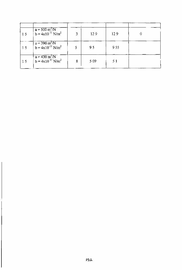
1 5
a = 5 0 0 m 2 / N
b = 4 x 1 0 1 1 N / m 2 3 1 2 9 1 2 9 0
1 5
a = 3 9 0 m 2 / N
b = 4 x 1 O ' 1 1 N / m 2 5 9 5 9 5 5
1 5
a = 4 3 0 m 2 / N
b = 4 x 1 0 1 1 N / m 2 8 5 0 9 5 1
I 5 Z

R esults F or G lycerine
S p e e d
m / s e c
V a l u e s o f
P r e s s u r e
C o e f f i c i e n t s
G a p r a t i o
h , / h 2
E x p e r i m e n t a l
P r e s s u r e
( P + h )
b a r
T h e o r e t i c a l
P r e s s u r e
( p + h )
b a r
P e r c e n t a g e
o f e r r o r
*
0 5 a = 2 9 5 m 2 / N
b = 4 x 1 0 1 1
3 4 4 6 1 5
0 5 a = 3 0 0 m 2 / N
b = 4 x 1 0 "
5 3 2 3 6 9 1 3 7 5
0 5 a = 3 0 0 m 2 / N
b = 4 x l 0 1 1
8
1 0 a = 3 0 0 m 2 / N
b = 4 x 1 0 1 1
3 8 4 8 5 1 3
1 0 a = 3 0 0 m 2 / N
b = 4 x 1 0 1 1
5 3 5 8 6 4 6 3 0 3
1 0 a = 3 0 0 m 2 / N
b = 4 x 1 0 1 1
3 129 12 53 2 6
1 5a = 3 0 0 m 2 / N
b = 4 x 1 0 1 1
5 95 93 2 1
I 5 a = 3 0 0 m 2 / N
b = 4 x 1 0 1 1
8 5 09 49 37
/ 5 3

D A T A F O R S I L I C O N 5
S p e e d
m / s e c
V a l u e s o f
P r e s s u r e
C o e f f i c i e n t s
G a p r a t i o
h , / h 2
E x p e r i m e n t a l
P r e s s u r e
( p + h )
b a r
T h e o r e t i c a l
P r e s s u r e
( p + h )
b a r
P e r c e n t a g e
o f e r r o r
* 2 a = 5 0 0 0 m2/N b = 5 x 1 0 11 N/m2
5 3 5 8 3 1 9 8 6 4 4 5 7
2 a = 8 5 0 0 m2/N b = 5 x 1 0 11 N/m2
5 3 5 8 3 2 9 7 1 7 1
2 a = 4 0 0 0 m2/N b = 4 x 1 0 11 N/m2
5 3 5 8 3 1 6 9 3 5 2
2 a = 8 0 0 0 m2/N b = 4 x 1 0 "N/m 2
5 3 5 8 3 2 8 7 7 1 9 7 0
1 5 a = 7 5 0 0 m2/N b = 5 x 1 0 " N/m2
5 3 1 6 9 2 9 7 2 4
1 5 a = 2 9 5 m2/N b = 5 x 1 0 " N/m2
3 3 0 0 4 2 9 3 1 2 4
1 5 a = 7 5 0 0 m2/N b = 5 x 1 0 11 N/m2
8 2 2 0 5 2 0 8 4 5 6
1 0 a = 8 0 0 0 m2/N b = 5 x 1 0 " N/m2
5 2 6 4 6 2 8 3 1 6 9
1 0 a = 8 0 0 0 m2/N b = 5 x 1 0 " N/m2
3 2 4 4 2 6 6 3 9 1
1 0 a = 2 9 5 m2/N b = 4 x 1 0 " N/m2
8 1 8 1 9 2 0 5 7 1 3

0 5 a = 7 5 0 0 m 2 / N
b = 5 x 1 0 1 1 N / m 2
5 1 8 5 2 4 1 2 9 5
0 5 a = 7 5 0 0 m2/N b = 5 x 1 0 1 1 N/m2
3 1 7 5 2 1 5 8 2 3
0 5 a = 7 5 0 0 m 2 / N
b = 5 x 1 0 1 1 N/m28 1 4 4 7 1 8 1 3 2 5
>0 2 5 a = 7 5 0 0 m 2 / N
b = 5 x 1 0 1 1 N / m 2
5 1 7 1 2 2 6 9 3 1 9
0 2 5 a = 7 5 0 0 m 2 / N
b = 5 x 1 0 ' ‘ N / m 2
3 1 5 1 1 9 6 3 3 0
0 2 5 a = 7 5 0 0 m 2 / N
b = 5 x 1 0 1 1 N / m 2
8 1 2 0 2 8 1 7 4 5 4 5
0 2 5 a = 1 0 , 0 0 0 m 2 / N
b = 8 x 1 0 1 1 N / m 2
5 1 7 1 3 0 4 8 7 8
0 2 5 a = 1 0 , 0 0 0 m 2 / N
b = 8 x 1 0 1 1 N / m 2
3 1 5 1 2 5 9 4 7 1
0 2 5
a = 1 0 , 0 0 0 m 2 / N
b = 8 x 1 0 1 1 N / m 2 8 1 2 0 2 8 2 3 1 9 9 2
0 5 a = 1 0 , 0 0 0 m 2 / N
b = 8 x 1 0 1 1 N / m 2
5 1 8 6 3 1 9 3 7 1
0 5 a = 1 0 , 0 0 0 m 2 / N
b = 8 x 1 0 1 1 N / m 2
3 1 7 5 2 7 9 4 6 1
0 5 a = 1 0 , 0 0 0 m 2 / N
b = 8 x 1 0 1 1 N / m 2
8 1 4 4 7 2 3 8 0 6 4
1 0 a = 1 0 , 0 0 0 m 2 / N
b = 8 x 1 0 1 1 N / m 2
5 2 6 4 6 3 4 8 3 3 1 6
154

1 0 a = 1 0 , 0 0 0 m 2 / N
b = 8 x l 0 " N / m 2
3 2 4 4 3 1 9 1 3 0 7
1 0 a = 1 0 , 0 0 0 m 2 / N
b = 8 x 1 0 1 1 N / m 2
8 1 8 1 9 2 5 2 3 8
* 1 5
a = 1 0 , 0 0 0 m 2 / N
b = 8 x 1 0 1 1 N / m 2
5 3 1 6 9 3 7 7 1 8
1 5 a = 1 0 , 0 0 0 m 2 / N
b = 8 x 1 0 1 1 N / m 2
3 3 0 0 4 3 5 8 4 1 9 4
1 5 a = 1 0 , 0 0 0 m 2 / N
b = 8 x 1 0 1 1 N / m 2
8 2 2 0 5 2 6 5 6 2 0
2 0 a = 1 0 , 0 0 0 m 2 / N
b = 8 x 1 0 1 1 N / m 2
5 3 5 8 9 4 0 5 5 1 2
2 0 a = 1 0 , 0 0 0 m 2 / N
b = 8 x 1 0 1 1 N / m 2
3 3 3 0 7 3 9 7 1 2 0
2 0 a = 1 0 , 0 0 0 m 2 / N
b = 8 x 1 0 1 1 N / m 2
8 2 6 1 8 2 7 8 9 6 9
2 0 a = 8 7 0 0 m 2 / N
b = 5 x 1 0 1 1 N / m 2
5 3 5 8 4 3 5 7 4 0 2 7
1 5 a = 8 2 0 0 m 2 / N
b = 8 x 1 0 1 1 N / m 2
5 3 1 6 9 3 1 6 9 0
1 0 a = 7 3 4 0 m 2 / N
b = 8 x 1 0 1 1 N / m 2
5 2 6 9 7 2 6 4 7 0
0 5 a = 6 0 0 0 m 2 / N
b = 8 x 1 0 1 1 N / m 2
5 1 6 4 4 1 6 5 0 0 3 6
»5*5