development of a portable welding robot with ethercat ... · development of a portable welding...
TRANSCRIPT
Abstract—This paper presents a portable robot that is to use for
welding process in shipbuilding yard. It has six degree of freedom and
3kg payload capability. Its weight is 21.5kg so that human workers can
carry it to the work place. Its body mainly made of magnesium alloy
and aluminum alloy for few parts that require high strength. Since the
distance between robot and controller should be 50m at most, the robot
controller controls the robot through EtherCAT. RTX and KPA are
used for real time EtherCAT control on Windows XP. The
performance of the developed robot was satisfactory, in welding of U
type cell in shipbuilding yard.
Keywords—Portable welding robot, Shipbuilding, EtherCAT
I. INTRODUCTION
UTOMATION in ship-building yard possessed many
difficulties. Among such difficulties, this paper is focused
on portability problem. Since the most work-pieces in
shipbuilding yard are very huge, they cannot be moved to the
fabricating devices. Instead, the devices should be placed near
the work-pieces through many obstacles such as access holes
and fences. Moreover, the cables for power and control are
relatively long and they cause other difficulties in handling
devices.
In such environment, portable welding carriages are widely
used because they are very compact, light and effective for
simple tasks. So, huge number of welding carriages is used in
shipbuilding yard for relatively simple welding tasks such as
straight line weld. In the meanwhile, since one type of carriage
can perform only a specific task, few types of carriage should
be work together when a work cell consists of different tasks.
For example, a U-cell consists of horizontal strait line welding
and vertical weaving welding and workers use two types of
carriages: horizontal carriage and vertical weaver. It induces
increased working time owing to the setting of the devices.
Moreover these carriages have another weakness. They cannot
weld at the starting and finishing edge areas of about 100mm
respectively due to the lack of welding-torch angle control
mechanism.
This work therefore developed a portable robot that can
perform various welding tasks in a work cell. Once worker sets
the robot in a cell it performs all required welding job. Worker
therefore can do another task after setting the robot.
In order to realize light weighted portable robot authors
employed magnesium alloy as a main material for robot body
J. Park et al. are with the Daewoo Shipbuilding and Marine Engineering Co.
Ltd., Seoul Korea (phone: 822-3667-3813, fax: 822-3667-3819; e-mail: [email protected]).
and EtherCAT technology in control architecture. Magnesium
alloy is used to minimize the body weight of the robot that has 6
degree of freedom and 3kg payload ability. Since the
magnesium alloy is relatively weak than aluminum alloy, some
critical parts are made of aluminum alloy.
EtherCAT[1] is employed to device the robot and controller
over long cable. Since the distance between controller and
robot should be 50m, a reliable communication is necessary for
this connection. So, EtherCAT is selected because its reliability
and real-time performance are well proven in many
applications [2,3]. Moreover, since it uses conventional
Ethernet port and does not require additional hardware, it helps
to implement relatively simple hardware.
Control program is written on Window XP. RTX [4] from
IntervalZero is added to realize real time control on Windows
XP and KPA EtherCAT master [5] from Coenig is used for
EtherCAT communication.
The developed robot is tested in a block building shop of
shipbuilding yard for welding task of U-type cell. Robot
operator places the robot at the front of the U-cell on the guide
line of laser strip. Offline program (OLP) module then
generates robot job program automatically based on the shape
and size of the cell. The robot finds exact welding position with
a touch sensor and performs welding according to the robot job
program.
This paper organized as follows: Section 2 presents the
requirements and development strategy of portable welding
robot and section 3 presents the hardware and software of the
robot. Application example and results are presented in section
4 and conclusions follow.
II. REQUIREMENTS AND STRATEGY
A. Requirements
The developed robot must be light enough that a worker can
carry it over cross-bars and access-holes of ship blocks. The
target weight of the robot is 20kg, which is the recommended
maximum payload of human workers.
The target payload of the robot is 3kg. Since the weight of
welding torch and cable is 1.5 kg and various sensors will be
added on the tip, payload 3kg is minimum specification of the
robot.
The required working width is 900mm and height 800mm.
The working depth is related to the robot location from the
work piece and it is decided to be 600mm.
As basic functions, the robot must have electric break for
safety and absolute encoder for fast boot up.
Juyi Park, Sang-Bum Lee, Jin-Wook Kim, Ji-Yoon Kim, Jung-Min Kim, Hee-Hwan Park, Jae-Won Seo,
Gye-Hyung Kang, and Soo-Ho Kim
Development of a Portable Welding Robot with
EtherCAT Interface
A
World Academy of Science, Engineering and Technology 60 2011
733

B. Development Strategy
Magnesium alloy is selected as main material for the robot
body because it is lighter than aluminum alloy that is very
popular material for robot body. Most parts are fabricated using
magnesium except some shaft which should have high strength.
EtherCAT is an important communication method in this
system. Since the robot controller and robot are connected
through 50m long cable. The connection must be very reliable
and the cable should not be too thick for easy handling. So
EtherCAT is employed for the connection, because its
performance and reliability are well proven from many
applications and it requires only one LAN cable for connection.
Therefore servo drives are installed near motors in robot body
and they communicate with main controller through EtherCAT.
Table I shows the specifications designed according to the
requirements above.
III. DEVELOPMENT
A. Robot Body
Magnesium alloy, AZ31 [7], is main material of the robot. Its
density is 1.7 g/cm3 and it is lighter than aluminum alloy,
A6061, of which density is 2.7 g/cm3. The strength and other
properties are listed in following table. As shown in the table,
the strength of magnesium alloy is lower than aluminum alloy.
Aluminum alloy therefore is used for some critical part that has
to be strong.
Motors in the robot are AC servo motors from Tamagawa:
model 4601, 4602 and 4603. They all have electric brakes and
absolute encoders, their capacities are 30w, 50w and 100w,
respectively. As transmissions, Harmonic drives are used with
timing belt. The resultant reduction ratios are 120, 451, 353,
100, 100 and 90, respectively.
Fig. 1 and 2 shows the schematic of the robot body. The link
length are designed based on the required work space and
verified through series of simulation using ROBCAD. Three
magnets are placed bottom of the robot to support the robot
during motion. Handles are also attached to the body for it is a
portable robot.
Resultant weight of robot body is 21.9 kg without tool. It is
heavier by 1.9kg than desired weight. It is mainly caused to the
thick forearm, which is originally designed very thin but was
reinforced after finishing welding test.
Fig. 1 Schematic of robot
Fig. 2 Robot body
B. Robot Controller hardware
Robot is in ship-block while its controller is located out of
the block, beside the wall of shop. They are connected through
one long cable which contains power, communication and I/O
signal lines. Four power lines transmit DC 24V 50A and
DC12V 5A. Four communication lines are used for EtherCAT
and another four lines for Ethernet. Six I/O lines are for
emergency stop switches and power control switch. Beside the
TABLE I SPECIFICATION OF PORTABLE WELDING ROBOT
Item Specification
Robot weight 20 kg
Payload 3 kg
Working radius 794mm
Accuracy of repetitions +/- 0.1 mm
Freedom 6 rotating joints
Position sensor Absolute encoder
Actuator AC servo motor
TABLE II MECHANICAL PROPERTIES OF MAGNESIUM AND ALUMINUM ALLOY
Property Unit Magnesium
Alloy, AZ31
Aluminum
Alloy, 6061
Tensile strength Mpa 255 310
Yield strength Mpa 200 276
Elongation % 12 12
Young’s modulus Gpa 45 68.3
Hardness HB 49 95
World Academy of Science, Engineering and Technology 60 2011
734
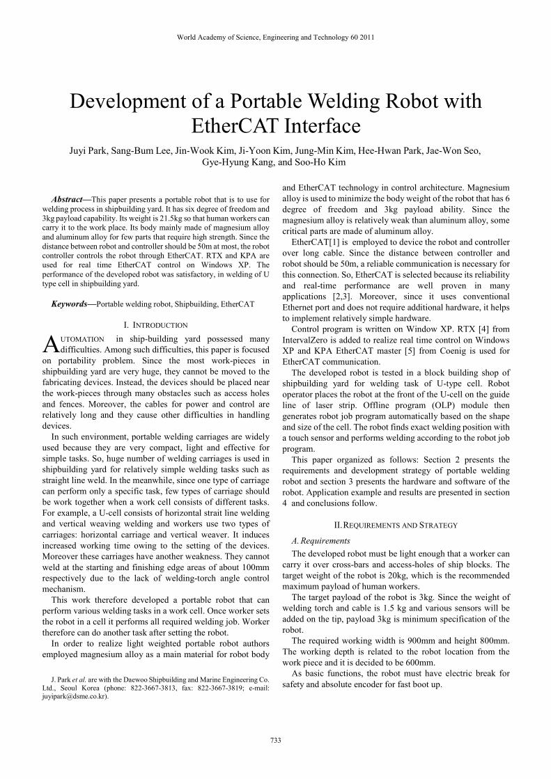
robot control cable there is all-in-one welding cable which
contains welding plus line, welder control lines and gas hose.
The block diagram in Fig.3 shows the hardware structure of the
robot controller.
Fig. 3 Block diagram of robot controller
In the developed controller EtherCAT is employed because it
is the well proven technology over many applications, and the
control hardware’s structure can be very simple. Since
EtherCAT enables real-time control through Ethernet port of
common PC board, it can be easily implemented on common
single board computer.
Control hardware consists of single board computer, power
supply and I/O modules. Detailed specifications are shown in
following table.
Servo drive is AEM of Copley Controls [6]. It supports AC
servo motor control with CAN over EtherCAT (COE) and
absolute encoder interface including SSI, EnDat and Absolute
A.There are two kind of I/O method in controller. One is to use
EtherCAT I/O module and other is to use I/O pin of servo drive.
The former is used for welder interface and emergency stop
switches and the latter for motor brake, status lamp and sensor
input.
C. Robot Controller Software
Control program is developed under Window XP. RTX is
added to enhance the real-time control performance and KPA
EtherCAT master is used for servo communication.
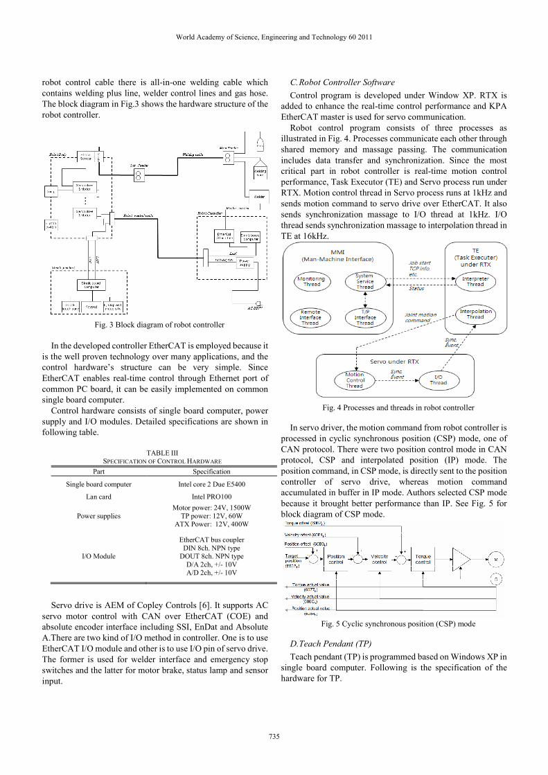
Robot control program consists of three processes as
illustrated in Fig. 4. Processes communicate each other through
shared memory and massage passing. The communication
includes data transfer and synchronization. Since the most
critical part in robot controller is real-time motion control
performance, Task Executor (TE) and Servo process run under
RTX. Motion control thread in Servo process runs at 1kHz and
sends motion command to servo drive over EtherCAT. It also
sends synchronization massage to I/O thread at 1kHz. I/O
thread sends synchronization massage to interpolation thread in
TE at 16kHz.
Fig. 4 Processes and threads in robot controller
In servo driver, the motion command from robot controller is
processed in cyclic synchronous position (CSP) mode, one of
CAN protocol. There were two position control mode in CAN
protocol, CSP and interpolated position (IP) mode. The
position command, in CSP mode, is directly sent to the position
controller of servo drive, whereas motion command
accumulated in buffer in IP mode. Authors selected CSP mode
because it brought better performance than IP. See Fig. 5 for
block diagram of CSP mode.
Fig. 5 Cyclic synchronous position (CSP) mode
D. Teach Pendant (TP)
Teach pendant (TP) is programmed based on Windows XP in
single board computer. Following is the specification of the
hardware for TP.
TABLE III SPECIFICATION OF CONTROL HARDWARE
Part Specification
Single board computer Intel core 2 Due E5400
Lan card Intel PRO100
Power supplies
Motor power: 24V, 1500W
TP power: 12V, 60W ATX Power: 12V, 400W
I/O Module
EtherCAT bus coupler
DIN 8ch. NPN type DOUT 8ch. NPN type
D/A 2ch, +/- 10V A/D 2ch, +/- 10V
World Academy of Science, Engineering and Technology 60 2011
735

CPU board is an off-the-self commercial board and Keypad
interface board is implemented using PIC16F877. Fig. 6 and 7
shows the block diagram of teach pendant hardware and GUI
on TP screen, respectively. TP is connected to the robot
controller through Ethernet with TCP/IP protocol.
Fig. 6 Block diagram of Teach pendant
Fig. 7 GUI of Teach Pendant
IV. APPLICATION
First target of this robot is welding task of U type cell (U-cell)
that consists of horizontal line and vertical weaving welding
tasks as shown in Fig. 8. Since there are plenty of U-cells in
ship blocks, authors selected this application.
An off-line program (OLP) module is developed to cover
various size and shape of U-cell. The shape of U-cell is
depending on the location of scallop hole and collar plate. Once
worker selects proper shape from OLP UI and input
approximated dimension, OLP generate a job file which is a
series of robot command to perform full welding tasks of the U
cell.
Fig. 8 Typical U-cell welding task
The location of robot in U-cell is not known exactly because
the robot is manually placed by hands. And the dimension of
the work-piece may not be correct because they are manually
fabricated in the previous process – such dimension error is
usually neglected in shipbuilding yard. So, line laser and touch
sensors are installed to compensate such error. The robot has
line laser diode at the front and right sides of its base, in order to
let workers place the robot at the right position. When worker
sets the robot, he or she has to adjust the robot position so that
the laser lines meet the cross line of front and right side of the
U-cell.
Touch sensor helps the robot find the correct welding points.
The principle of touch sensor is very simple. DC plus line is
connected to the welding torch and minus to the work-piece.
Controller checks if the torch touched the work-piece while the
torch moves to the work-piece. As a result, this sensor can be
used to find the correct location of work-pieces.
Fig. 9 and 10 shows the real pictures taken while operator
handle and execute the robot for welding job. In conventional
task, workers use two different types of welding carriages for
this task: normal linear weaving carriage for horizontal welding
and so-called vertical weaver for vertical welding. In addition,
worker should perform manual welding for edge parts of the
U-cell because there remains un-welded region of welding
carriage. So, workers must install carriages three or four times
depending on the shape and do manual welding in conventional
U-cell welding. On the contrary, workers do only one setting
for the portable welding robot without manual welding. As a
result, the robot reduced the time and effort of workers.
In the meanwhile, there are few shortcomings of the
developed robot. It is still heavy to carry. The weight of the
robot body is 21.9kg and welding torch with a shock sensor and
cable weighs 3.8kg. Since the worker must move the robot
body, torch and cable together, he or she has to move 25.7kg at
once. It has to be reduced more for better portability. High price
of the robot is another shortcoming which mainly caused by use
of magnesium alloy. The price can be reduced when it is
massively produced.
TABLE IV
SPECIFICATION OF TEACH PENDANT
Part Specification
Processor Intel Atom N270 1.6GHz
Memory DDR II 1G
HDD CF type II 16G
Display 7“ wide WVGA touch screen Key-pad 24 key, Metal-Dom switch
Switch E. stop, Mode, Enable
Power DC 12V, 23W Battery Lithium polymer, 1000mAh
O/S Windows XP
World Academy of Science, Engineering and Technology 60 2011
736
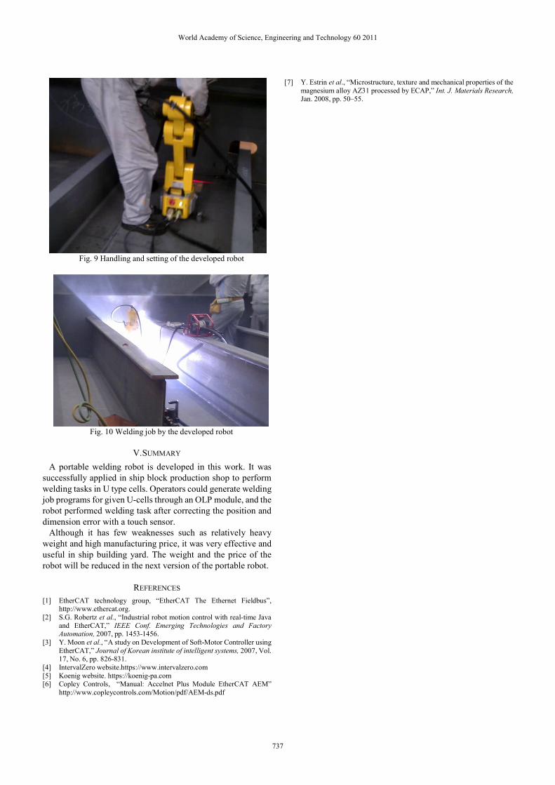
Fig. 9 Handling and setting of the developed robot
Fig. 10 Welding job by the developed robot
V. SUMMARY
A portable welding robot is developed in this work. It was
successfully applied in ship block production shop to perform
welding tasks in U type cells. Operators could generate welding
job programs for given U-cells through an OLP module, and the
robot performed welding task after correcting the position and
dimension error with a touch sensor.
Although it has few weaknesses such as relatively heavy
weight and high manufacturing price, it was very effective and
useful in ship building yard. The weight and the price of the
robot will be reduced in the next version of the portable robot.
REFERENCES
[1] EtherCAT technology group, “EtherCAT The Ethernet Fieldbus”, http://www.ethercat.org.
[2] S.G. Robertz et al., “Industrial robot motion control with real-time Java and EtherCAT,” IEEE Conf. Emerging Technologies and Factory Automation, 2007, pp. 1453-1456.
[3] Y. Moon et al., “A study on Development of Soft-Motor Controller using
EtherCAT,” Journal of Korean institute of intelligent systems, 2007, Vol. 17, No. 6, pp. 826-831.
[4] IntervalZero website.https://www.intervalzero.com
[5] Koenig website. https://koenig-pa.com [6] Copley Controls, “Manual: Accelnet Plus Module EtherCAT AEM”
http://www.copleycontrols.com/Motion/pdf/AEM-ds.pdf
[7] Y. Estrin et al., “Microstructure, texture and mechanical properties of the
magnesium alloy AZ31 processed by ECAP,” Int. J. Materials Research, Jan. 2008, pp. 50–55.
World Academy of Science, Engineering and Technology 60 2011
737