development of a segway-type wheelchair
TRANSCRIPT
Development of a Segway-Type Wheelchair
by
Kittipong Pramotago
A thesis submitted in partial fulfillment of the requirements for the
degree of Master of Engineering in
Mechatronics
Examination Committee: Prof. Manukid Parnichkun (Chairperson)
Assoc. Prof. Erik L.J. Bohez
Dr. Mongkol Ekpanyapong
Nationality: Thai
Previous Degree: Bachelor of Engineering in Mechanical Engineering
Ubon Ratchathani University
Thailand
Scholarship Donor: Royal Thai Government Fellowship – AIT Fellowship
Asian Institute of Technology
School of Engineering and Technology
Thailand
May 2017

ii
ACKNOWLEDGEMENTS
Firstly, I would like to thanks to my thesis advisor, Prof. Manukid Parnichkun. He is a
lots of knowledge and other experiences in mechanical and control engineering system.
Moreover, he giving me a suggestion, interesting lecture and simulation throughout my
thesis.
Secondly, I also would like a special thanks to committee Assoc. Prof. Erik L.J. Bohez
and Dr. Mongkol Ekpanyapong for the recommendation provided during thesis work.
They are very important to help me about my thesis.
Thirdly, my special thanks go to my friend and my senior, Mr. Warawut Suwalai and Mr.
Surachat Chantarachit to supporting, suggestions and many techniques.
Fourthly, I would like to thankful to my family for support in every way. In addition,
Royal Thai Government Fellowship – AIT Fellowship provided me a great opportunity
for study in AIT.
Finally, my thesis cannot be finished if I do not have all of help form Mechatronics, senior
students, my friends and all staff. They have suggestion and special techniques for me.
Thank you so much.
iii
ABSTRACT
The difficult challenge in a Segway type wheelchair is to control the robot which can
balance two wheels in roll or pitch direction. There are many techniques to balance a
Segway type wheelchair. In about thesis, the inverse pendulum technique is applied to
balancing in the longitudinal direction. Many section in this thesis used balance such as
the fusion sensor (Gyroscope & accelerometer), the dynamic model and the control
algorithm. This thesis concerns about the control algorithm to control the robot. The PID
controller is applied to the simulation model and the real plant in order to observe the
response of the robot. Finally all thesis, the simulation and experiment result are presented
and discussion. The simulation result uses the Simulink in the Matlab program to simulate
form dynamic model.
Keywords: a Segway type wheelchair, Newton Euler method, PID controller,
Dynamic model

iv
TABLE OF CONTENTS (Cont’l)
CHAPTER TITLE PAGE
TITLE PAGE ACKNOWLEDGEMENTS ii
ABSTRACT iii
TABLE OF CONTENTS iv
LIST OF FIGURES vi
LIST OF TABLES vii
LIST OF SYMBOLS viii
1. INTRODUCTION 2
1.1 Background 2
1.2 Statement of the problems 3
1.3 Objectives 3
1.4 Scopes of works 3
1.5 Limitations 3
2. LITERATURE REVIEW 4
2.1 Introduction 4
2.2 Research on the balancing concept 4
2.3 State space control algorithm 7
2.4 PID control algorithm 8
2.5 Linear model of a direct current (DC) motor 10
3. METHODOLOGY 11
3.1 Methodology flow chart 11
3.2 Mechanical model 12
3.3 Physical model 14
3.4 Electrical hardware configurations 15
3.4.1 Microcontroller features 16
3.4.2 Driver DC motor board 16
3.4.3 BNO055 (Gyro and accelerometer) 17
3.4.4 Regulator 17
3.4.5 DC motor with encoder 18
3.4.6 DC power supply features 18
3.4.7 Encoder 19
3.5 Dynamic model of a Segway type wheelchair 20
3.6 The state space model 27
3.7 Parameter identification 29
3.8 Control algorithms of a Segway-type robot 30
3.9 Data of experiment 31
4. RESULTS AND DISCUSSION 32
4.1 Simulation result in Matlab software 32
4.2 Experiment result 34

v
5. CONCLUSIONS AND FUTURE WORKS 35
5.1 Conclusions 35
5.2 Future works 35
REFERENCES 36
APPENDIX 37
Appendix A: C code for control a segway-type wheelchair

vi
LIST OF FIGURES
FIGURE TITLE PAGE
Figure 2.1 The two wheel inverted pendulum model [2] 4
Figure 2.2 The prototype robot balancing two wheel [4] 5
Figure 2.3 The iBot. The main features are highlighted 6
Figure 2.4 The SEGFREE, a Segway Wheelchair 7
Figure 2.5 System inputs and outputs 7
Figure 2.6 PID controller block diagram 9
Figure 2.7 Diagram of a DC motor 10
Figure 3.1 Methodology of flow chart to study 11
Figure 3.2 Parts of wheelchair design in SolidWorks 12
Figure 3.3 All parts assembly of wheelchir robot 13
Figure 3.4 Model of a Segway type wheelchair 13
Figure 3.5 Physical model of a Segway type wheelchair 14
Figure 3.6 Electrical and electronic hardware 15
Figure 3.7 Microcontroller Arduino MEGA 2560 16
Figure 3.8 H-bridge driver dc motor 80A 16
Figure 3.9 BNO055 sensor 17
Figure 3.10 Regulator output 5 V 17
Figure 3.11 DC motor 24 V 18
Figure 3.12 Battery 12 V-7AH 18
Figure 3.13 Encoder for counter motor 19
Figure 3.14 Free body diagram of the left wheel and the right wheel 20
Figure 3.15 The dynamic model of the body robot 21
Figure 3.16 Pole of system 30
Figure 3.17 Data of experiment balancing robot 31
Figure 4.1 The PID simulation model 33
Figure 4.2 The PID simulation result for balancing 33
Figure 4.3 Real robot for balancing 34
Figure 4.4 The PID experiment result of balancing 34

vii
LIST OF TABLES
TABLE TITLE PAGE
Table 2.1 Summary of researches about balancing of robot 4
Table 2.2 Summary of researches about balancing of robot 6
Table 2.3 Effects of increasing a parameter 9
Table 3.1 DC motor parameters 18
Table 3.2 Battery specifications 19
Table 3.3 The table of constant parameter for balancing 29
viii
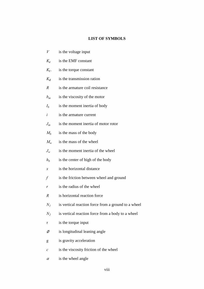
LIST OF SYMBOLS
V is the voltage input
𝐾𝑒 is the EMF constant
𝐾𝑡. is the torque constant
𝐾𝑑 is the transmission ration
R is the armature coil resistance
bm is the viscosity of the motor
Ib is the moment inertia of body
i is the armature current
Jm is the moment inertia of motor rotor
Mb is the mass of the body
Mw is the mass of the wheel
Jw is the moment inertia of the wheel
hb is the center of high of the body
x is the horizontal distance
f is the friction between wheel and ground
r is the radius of the wheel
R is horizontal reaction force
N1 is vertical reaction force from a ground to a wheel
N2 is vertical reaction force from a body to a wheel
τ is the torque input
∅ is longitudinal leaning angle
g is gravity acceleration
c is the viscosity friction of the wheel
α is the wheel angle
2
CHAPTER 1
INTRODUCTION
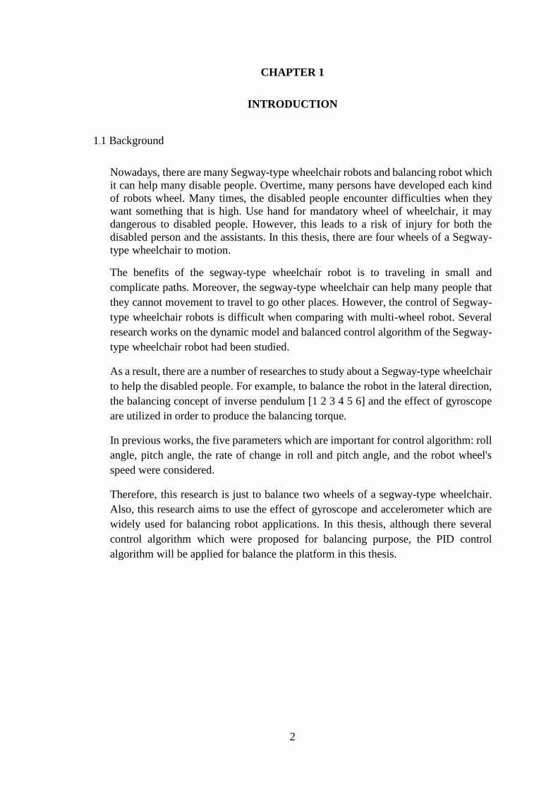
1.1 Background
Nowadays, there are many Segway-type wheelchair robots and balancing robot which
it can help many disable people. Overtime, many persons have developed each kind
of robots wheel. Many times, the disabled people encounter difficulties when they
want something that is high. Use hand for mandatory wheel of wheelchair, it may
dangerous to disabled people. However, this leads to a risk of injury for both the
disabled person and the assistants. In this thesis, there are four wheels of a Segway-
type wheelchair to motion.
The benefits of the segway-type wheelchair robot is to traveling in small and
complicate paths. Moreover, the segway-type wheelchair can help many people that
they cannot movement to travel to go other places. However, the control of Segway-
type wheelchair robots is difficult when comparing with multi-wheel robot. Several
research works on the dynamic model and balanced control algorithm of the Segway-
type wheelchair robot had been studied.
As a result, there are a number of researches to study about a Segway-type wheelchair
to help the disabled people. For example, to balance the robot in the lateral direction,
the balancing concept of inverse pendulum [1 2 3 4 5 6] and the effect of gyroscope
are utilized in order to produce the balancing torque.
In previous works, the five parameters which are important for control algorithm: roll
angle, pitch angle, the rate of change in roll and pitch angle, and the robot wheel's
speed were considered.
Therefore, this research is just to balance two wheels of a segway-type wheelchair.
Also, this research aims to use the effect of gyroscope and accelerometer which are
widely used for balancing robot applications. In this thesis, although there several
control algorithm which were proposed for balancing purpose, the PID control
algorithm will be applied for balance the platform in this thesis.
3
1.2 Statement of the problems
The problem of the people who are unable to walk because they have some problems
with their lower-limb part, for example, physical disabilities like polio, blindness,
paralysis, and other deficiencies which affect their legs, should be solved. Those
problems can as a result in to make this research. The segway-type wheelchair is
similar to an inverted pendulum. There are techniques of a segway-type wheelchair
balancing. For the nonlinear model of a segway-type wheelchair, the linearization
should be used to transformed the nonlinear model to linear system model before the
step of analysis and design for the control algorithm.
The concept to control only the torque or speed of two wheels is a best for controlling.
By using the controller PID
1.3 Objectives
To design a controller for balancing the segway-type wheelchair robot
1.4 Scopes of works
The scopes of this thesis are as following:
Balancing wheelchair two-wheel.
Design a new prototype hardware of a Segway-type wheelchair
Using Microcontroller Arduino MEGA 2560 discovery and Matlab Simulink
1.5 Limitations
The limitations of this thesis are as following:
Define the dynamics of segway-type wheelchair robot.
All Weight limit at 100 kg

4
CHAPTER 2
LITERATURE REVIEW
2.1 Introduction
In this literature review, there is research works to make the robot balanced itself and there
are many ways to balance out the robot which will be reviewed in the following topics: The
balancing concept of robot to control algorithms.
2.2 Research on the balancing concept
There are several concepts to perform a balancing the robot which were proposed. Some
of the research used inverted pendulum theory. In addition, there are the gyroscope and
accelerometer to effect on angle of body robot which can produce a stable system.
Moreover, the angular momentum theory can applied to torque dc motor.
Table 2.1 Summary of researches about balancing of robot
Ref Topic Control Results
[1] Robust Control Method Applied in
Self-Balancing Two-Wheeled Robot
SMC
technique
Simulation and
Experiment
[2] A Two-Wheeled Self-Balancing Robot
with the Fuzzy PD Control Method
Fuzzy PD Simulation and
Experiment
[3] Self-balancing two-wheeled robot LQR Simulation and
Experiment
[4] Balancing a Two-Wheeled
Autonomous Robot
PID and
LQR
Simulation and
Experiment
Figure 2.1 The two wheel inverted pendulum model [2]

5
In the researches on balancing control of two wheel robot [1 2 3 4], the SMC technique
were used to control a SBTWR system by HerTerng Yau et al. [1]. It consists of two major
steps. First, the stability dynamics must be confirmatory by switching surface. Second, the
hitting of the switching surfaces should be ensured from determination of a SMC in this
step.
Next, Junfeng Wu et al. [2] used the Fuzzy PD Controller. The robot structure is a
composition of a chassis carrying a DC motor coupled to a planetary gearbox. The digital
signal processing board was used to implement the control algorithm. The power
amplifiers were selected for the the motors. The necessary sensors are used to sense the
state of the robot. And the receiver for the radio control unit, as well as a vertical bar. The
two-wheel inverted pendulum model is in Figure 2.1.
The state feedback with used Linear Quadratic Regulator (LQR) was proposed by Brian
Bonafilia et al. [3]. Result of the simulation found that the Kalman Filter are using
the state estimated. The control system stability by using the gyroscope and
accelerometer sensor. The error angle using the LQR controller. There are three main
sensor: the accelerometer 3 axis, the gyroscope 1 axis and motor with encoders
were used to estimate the current state of the system.
Rich Chi Ooi [4] used Linear Quadratic Regulator (LQR) and PID controller. This is a
prototype robot balancing two wheel in Figure 2.2.
Figure 2.2 The prototype robot balancing two wheel [4]
6
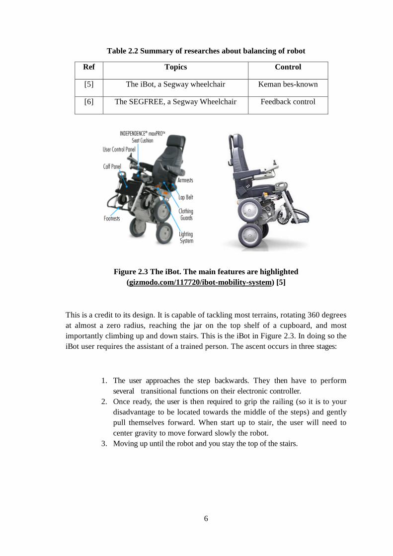
Table 2.2 Summary of researches about balancing of robot
Ref Topics Control
[5] The iBot, a Segway wheelchair Keman bes-known
[6] The SEGFREE, a Segway Wheelchair Feedback control
Figure 2.3 The iBot. The main features are highlighted
(gizmodo.com/117720/ibot-mobility-system) [5]
This is a credit to its design. It is capable of tackling most terrains, rotating 360 degrees
at almost a zero radius, reaching the jar on the top shelf of a cupboard, and most
importantly climbing up and down stairs. This is the iBot in Figure 2.3. In doing so the
iBot user requires the assistant of a trained person. The ascent occurs in three stages:
1. The user approaches the step backwards. They then have to perform
several transitional functions on their electronic controller.
2. Once ready, the user is then required to grip the railing (so it is to your
disadvantage to be located towards the middle of the steps) and gently
pull themselves forward. When start up to stair, the user will need to
center gravity to move forward slowly the robot.
3. Moving up until the robot and you stay the top of the stairs.

7
Figure 2.4 The SEGFREE, a Segway Wheelchair
http://www.segfree.co.za/the-segfree.htm [6]
The Segfree [6] is the segway to balance two wheels to let the people ride. This Segway
robot is suitable for disabled people, the elderly or people walking legs. The Segfree
developed a Segway wheelchair. Robots used gyroscope to stabilize balancing. There are
to use feedback control. The main of the Segway to balance two wheels are left motor
and right motor which control the robot by gyroscope or accelerometer and two drive
motor which generated the robot forward, backward, turn left and turn right.
2.3 State space control algorithm
Before the design has to be mechanics model by using the state space equation to
stabilize balancing of the robot. The system consists of the A, B, C and D matrixes.
There are three parameter, inputs, state variable, and output. Thus, the state space provides
the dynamics with first-order differential equation.
Figure 2.5 System inputs and outputs

8
The properties of the system is the matrixes A and B which are determined by system
structure. The output matrixes C and D are determined by output variables. The standard
of state-space equation find dynamic system.
x(t)=Ax(t)+Bu(t)
y(t)=Cx(t)+Du(t)
Where:
x(t) : “state vector”
𝑦(𝑡) : “output vector”
u(t) : “input or control vector”
𝐴(𝑡) : “state or system matrix”
B(t) : “input matrix”
𝐶(𝑡) : “output matrix”
D(t) : “feed through”
And x(t)=d
dt x(t)
2.4 PID control algorithm
Type of feedback control algorithm is PID controller which PID is mean proportional, integral
and derivative. Normally PID controller basically used the error e(t) between the set
points and process variable. Therefore, a desire output given by the controller of the
error. The formula of PID shown as below. There are three terms of PID to calculate of total
gain.
u(t)= Kpe(t)+ Ki ∫ e(τ)dτ + Kd
d
dt
t
0
e(t

9
Where
u(t) : Input of system
Kp : The proportional gain
Ki : The integral gain
Kd : The derivative gain
e(t)=SP-PV(t) : The error of system
SP = set point and PV(t) = The process variable of system
t : Instantaneous times
e(τ) : Variable of the integration
Figure 2.6 PID controller block diagram
P gain is shown current values of the error I gain is shown previous values of the error
D gain is shown future values of the error
The adjusted value of gain, all of first is to set Ki and Kd to zero values. After that,
increase the Kp value until there is a loop oscillates system. Then adjust the Ki values to
increasing. On the other hand, if Ki value is very big, it will effect on unstable system.
Lastly, increasing Kd value until the system respond faster to reach. This is parameter for
setting to tuning method shown on table 2.3
Table 2.3 Effects of increasing a parameter
10
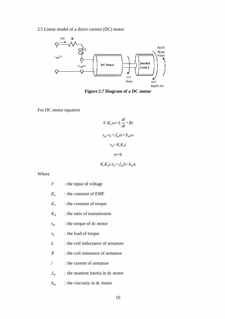
2.5 Linear model of a direct current (DC) motor
Figure 2.7 Diagram of a DC motor
For DC motor equation
V-Keω=Ldi
dt+Ri
τm-τL=Jmω+bmω
τm=KtKdi
ω=α
KtKdi-τL=Jmα+bmα
Where
V : the input of voltage
Ke : the constant of EMF
Kt. : the constant of torque
Kd : the ratio of transmission
τm : the torque of dc motor
τL : the load of torque
L : the coil inductance of armature
R : the coil resistance of armature
i : the current of armature
Jm : the moment inertia in dc motor
bm : the viscosity in dc motor
11
CHAPTER 3
METHODOLOGY
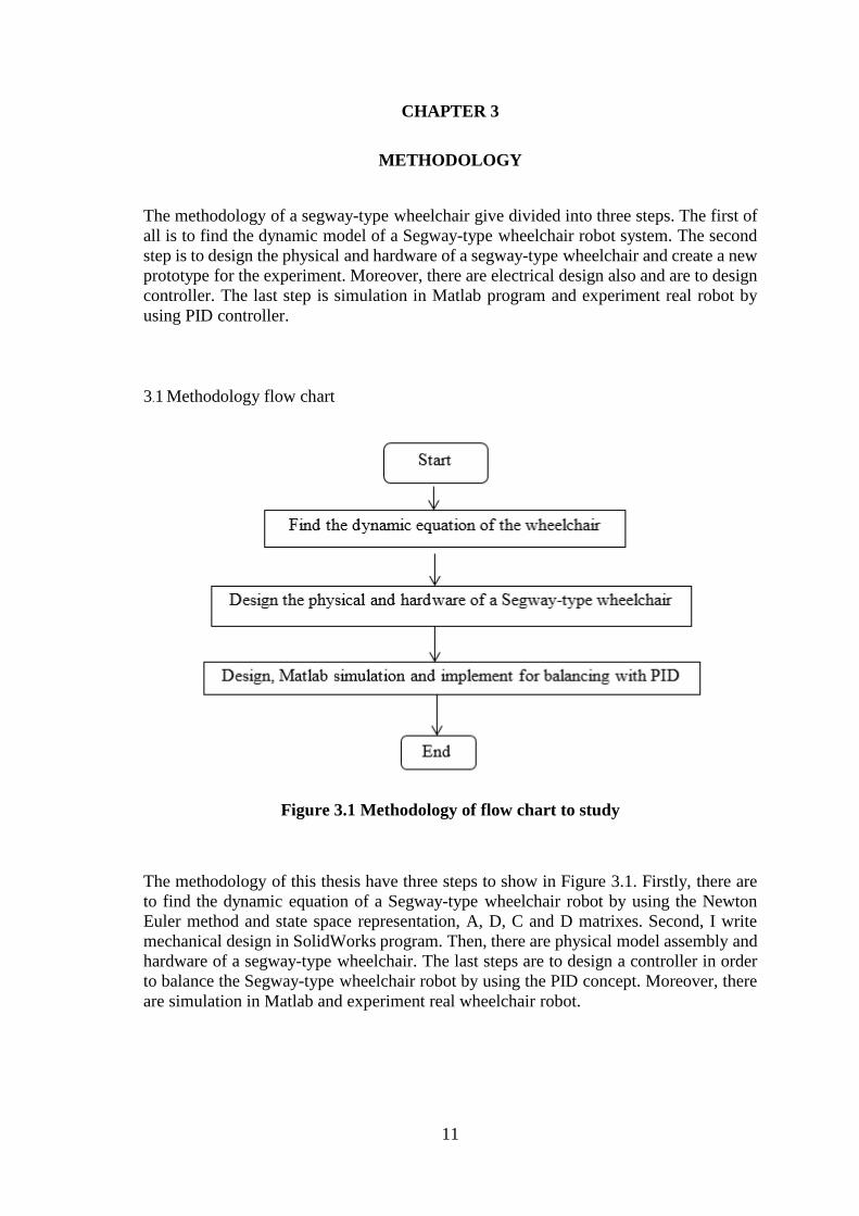
The methodology of a segway-type wheelchair give divided into three steps. The first of
all is to find the dynamic model of a Segway-type wheelchair robot system. The second
step is to design the physical and hardware of a segway-type wheelchair and create a new
prototype for the experiment. Moreover, there are electrical design also and are to design
controller. The last step is simulation in Matlab program and experiment real robot by
using PID controller.
3.1 Methodology flow chart
Figure 3.1 Methodology of flow chart to study
The methodology of this thesis have three steps to show in Figure 3.1. Firstly, there are
to find the dynamic equation of a Segway-type wheelchair robot by using the Newton
Euler method and state space representation, A, D, C and D matrixes. Second, I write
mechanical design in SolidWorks program. Then, there are physical model assembly and
hardware of a segway-type wheelchair. The last steps are to design a controller in order
to balance the Segway-type wheelchair robot by using the PID concept. Moreover, there
are simulation in Matlab and experiment real wheelchair robot.

12
3.2 Mechanical model
I designed the model a Segway type wheelchair itself. Figure 3.2 below. All parts of a
Segway type wheelchair has designed in SolidWorks program.
Figure 3.2 Parts of wheelchair design in SolidWorks

13
Then, all parts has designed of each part of a Segway-type wheelchair robot. Each parts
lead to assembly as the figure 3.3 which all assembly parts are importance for balancing
of a Segway-type wheelchair robot.
Figure 3.3 All part assembly of wheelchair robot
Therefore, this is of a Segway type wheelchair show on figure 3.4 as below. There are
there motor for control which left and right motor are balancing of control wheelchair
robot. Another motor is rotated of axis four wheels. A Segway type wheelchair has four
wheels because there are two function, balancing two wheels and up the stairs four
wheels.
Figure 3.4 Model of a Segway type wheelchair

14
3.3 Physical model
Real physical model of a Segway type wheelchair robot are importance to balancing.
There are many tools and equipment used doing wheelchair robot. All assembly of a
Segway type wheelchair are showing on figure 3.5 as below,
Figure 3.5 Physical model of a Segway type wheelchair

15
3.4 Electrical hardware configurations
The electrical and electronic circuit diagram of a Segway type wheelchair show on figure
3.6. The system of a Segway-type wheelchair robot consist of Microcontroller Arduino
MEGA 2560, three DC motor, three drive motor board, regular, three encoder, MPU6050
(Gyro & accelerometer fusion sensor) and two battery 12 V. All electrical and electronic
design are very importance to balance wheelchair robot.
Figure 3.6 Electrical and electronic hardware

16
3.4.1 Microcontroller features
Figure 3.7 Microcontroller Arduino MEGA 2560
Nowadays, there are many microcontroller for using to control robot balancing. However,
this thesis used the main of microcontroller Arduino MEGA 2560 board are given below.
There are 54 digital input/output pins. Moreover, PMW outputs can used 15 pin.
16 analog inputs, operation voltage 5V
4 UARATs (hardware serial ports), a USB connection, a power jack
I/O pin, current is 40 mA
3.3V pin, current is 50 mA
This microcontroller MEGA 2560 board can write program with the Arduino software
(IDE)
3.4.2 Driver DC motor board
Figure 3.8 H-bridge driver dc motor 80A
The main board are given below.
Output: DC supply 12-48V 80A and full-complementary power mosfet driver
Input: full opto-isollated input interface signals, 5V 8mA
Drive mode consist of on-off control, direction control and Speed control
Frequency of PWM = 400 Hz – 1000 Hz
17
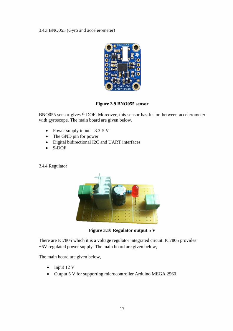
3.4.3 BNO055 (Gyro and accelerometer)
Figure 3.9 BNO055 sensor
BNO055 sensor gives 9 DOF. Moreover, this sensor has fusion between accelerometer
with gyroscope. The main board are given below.
Power supply input = 3.3-5 V
The GND pin for power
Digital bidirectional I2C and UART interfaces
9-DOF
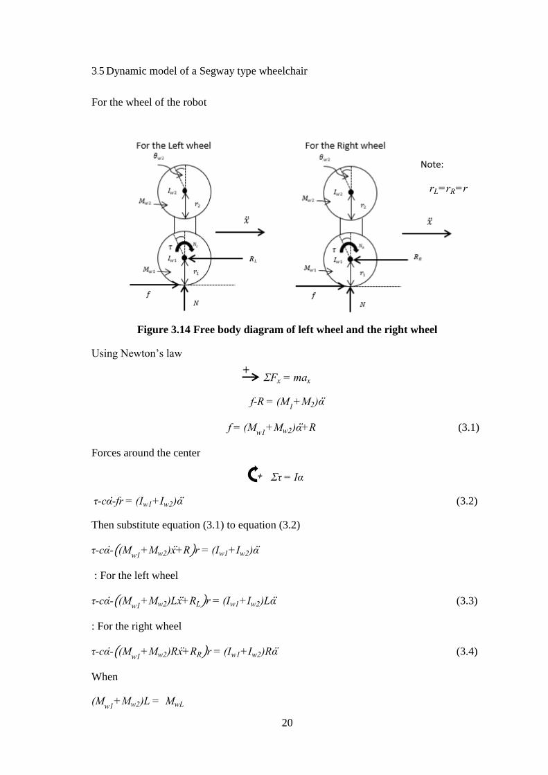
3.4.4 Regulator
Figure 3.10 Regulator output 5 V
There are IC7805 which it is a voltage regulator integrated circuit. IC7805 provides
+5V regulated power supply. The main board are given below,
The main board are given below,
Input 12 V
Output 5 V for supporting microcontroller Arduino MEGA 2560

18
3.4.5 DC Motor with encoder
Figure 3.11 DC motor 24 V
There are two dc motor for control balancing of robot and two encoder are counter push
of motor also. The main dc motor are given below,
Input DC ±24V
Output 100 rpm
Table 3.1 DC motor parameters
3.4.6 DC power supply features
Figure 3.12 Battery 12 V-7AH
This thesis, the robot used two battery for support Driver DC motor board ±24V.

19
Table 3.2 Battery specifications
3.4.7 Encoder
Figure 3.13 Encoder for counter motor
Encoders are used to measure cycle of rotating the motor. In order to know if the motor
rotates, encoder will be counter. This provided as below,
The output is an analog voltage such as 0-10V or ±5V
The output is an analog current such as a 4-20mA or 0-20 mA current loop.
The shaft shall be rotated at no load for a total of 20,000±1000 cycles, whereas 1
cycle is 360˚ rotation
20
+
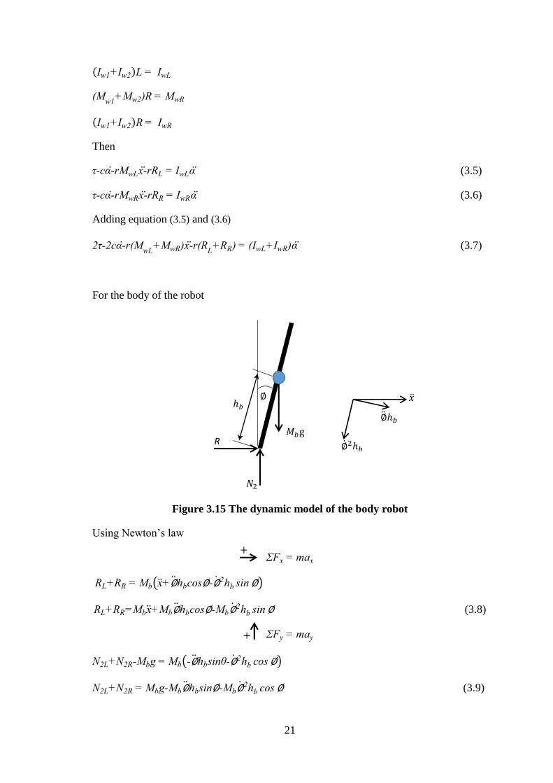
3.5 Dynamic model of a Segway type wheelchair
For the wheel of the robot
Figure 3.14 Free body diagram of left wheel and the right wheel
Using Newton’s law
ΣFx = max
f-R = (M1+M2)α
f = (Mw1
+Mw2)α+R (3.1)
Forces around the center
Στ = Iα
τ-cα-fr = (Iw1+Iw2)α (3.2)
Then substitute equation (3.1) to equation (3.2)
τ-cα-((Mw1
+Mw2)x+R)r = (Iw1+Iw2)α
: For the left wheel
τ-cα-((Mw1
+Mw2)Lx+RL)r = (Iw1+Iw2)Lα (3.3)
: For the right wheel
τ-cα-((Mw1
+Mw2)Rx+RR)r = (Iw1+Iw2)Rα (3.4)
When
(Mw1
+Mw2)L = MwL
+
Note:
rL=rR=r
21
+
+
(Iw1+Iw2)L = IwL
(Mw1
+Mw2)R = MwR
(Iw1+Iw2)R = IwR
Then
τ-cα-rMwLx-rRL = IwLα (3.5)
τ-cα-rMwRx-rRR = IwRα (3.6)
Adding equation (3.5) and (3.6)
2τ-2cα-r(MwL
+MwR)x-r(RL+RR) = (IwL+IwR)α (3.7)
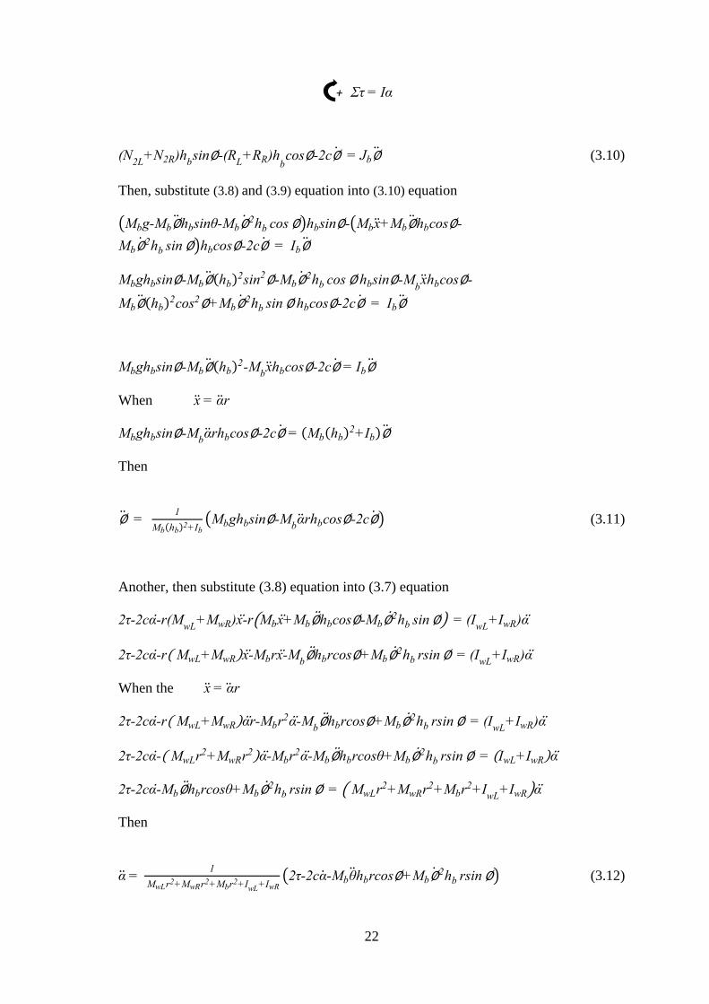
For the body of the robot
Figure 3.15 The dynamic model of the body robot
Using Newton’s law
ΣFx = max
RL+RR = Mb(x+∅hbcos∅-∅2hb sin ∅)
RL+RR=Mbx+Mb∅hbcos∅-Mb∅2hb sin ∅ (3.8)
ΣFy = may
N2L+N2R-Mbg = Mb(-∅hbsinθ-∅2hb cos ∅)
N2L+N2R = Mbg-Mb∅hbsin∅-Mb∅2hb cos ∅ (3.9)
∅2ℎ𝑏
∅ℎ𝑏
R
𝑁2
∅
𝑀𝑏g
ℎ𝑏
22
Στ = Iα
(N2L
+N2R)hbsin∅-(R
L+RR)h
bcos∅-2c∅ = Jb∅ (3.10)
Then, substitute (3.8) and (3.9) equation into (3.10) equation
(Mbg-Mb∅hbsinθ-Mb∅2hb cos ∅)hbsin∅-(Mbx+Mb∅hbcos∅-
Mb∅2hb sin ∅)hbcos∅-2c∅ = Ib∅
Mbghbsin∅-Mb∅(hb)2sin2∅-Mb∅
2hb cos ∅ hbsin∅-Mbxhbcos∅-
Mb∅(hb)2cos2∅+Mb∅
2hb sin ∅ hbcos∅-2c∅ = Ib∅
Mbghbsin∅-Mb∅(hb)2-M
bxhbcos∅-2c∅ = Ib∅
When x = αr
Mbghbsin∅-Mbαrhbcos∅-2c∅ = (Mb(hb)
2+Ib)∅
Then
∅ = 1
Mb(hb)2+Ib
(Mbghbsin∅-Mbαrhbcos∅-2c∅) (3.11)
Another, then substitute (3.8) equation into (3.7) equation
2τ-2cα-r(MwL
+MwR)x-r(Mbx+Mb∅hbcos∅-Mb∅2hb sin ∅) = (I
wL+IwR)α
2τ-2cα-r( MwL+MwR)x-Mbrx-Mb∅hbrcos∅+Mb∅
2hb rsin ∅ = (IwL
+IwR)α
When the x = αr
2τ-2cα-r( MwL+MwR)αr-Mbr2α-Mb∅hbrcos∅+Mb∅
2hb rsin ∅ = (IwL
+IwR)α
2τ-2cα-( MwLr2+MwRr2)α-Mbr2α-Mb∅hbrcosθ+Mb∅2hb rsin ∅ = (IwL+IwR)α
2τ-2cα-Mb∅hbrcosθ+Mb∅2hb rsin ∅ = ( MwLr2+MwRr2+Mbr2+I
wL+IwR)α
Then
α = 1
MwLr2+MwRr2+Mbr2+IwL+IwR(2τ-2cα-Mbθhbrcos∅+Mb∅
2hb rsin ∅) (3.12)
+

23
The process of linearization used to convert the unstable nonlinear model to linear model.
And θ ≈ 0
sin∅ ≈ θ
cos∅ ≈ 1
∅2𝜃 ≈ 0
The linearization is used in (3.11) and (3.12) equation
θ = 1
Mb(hb)2+Ib
(Mbghb∅-Mbαrhb-2c∅)
Where µ = Mb(hb)2+Ib
∅ = 1
µ(Mbghb∅-M
bαrhb-2c∅) (3.13)
Moreover
α = 1
MwLr2+MwRr2+Mbr2+IwL
+IwR
(2τ-2cα-Mb∅hbrcos∅+Mb∅2hb rsin ∅)
Where β = MwL
r2+MwRr2+Mbr2+IwL
+IwR
α = 1
β(2τ-2cα-Mb∅hbr) (3.14)
Substitute (3.14) equation into (3.13) equation
∅ =1
μ(Mbghb∅-M
brhb (
1
β(2τ-2cα-Mb∅hbr)) -2c∅)
∅ =1
μ(Mbghb∅- (
2τ Mbhbr
β-2cαMbhbr
β-(Mb)
2(hb)2r2∅
β) -2c∅)
∅ = (Mbghb
μ)∅- (
2Mbhbr
μβ) τ+ (
2Mbhbcr
μβ) α+ (
(Mb)2(hb)
2r2
μβ) ∅- (
2c
μ) ∅
(1-(Mb)
2(hb)2r2
μβ) ∅ = (
Mbghb
μ)∅- (
2Mbhbr
μβ) τ+ (
2Mbhbcr
μβ) α- (
2c
μ) ∅
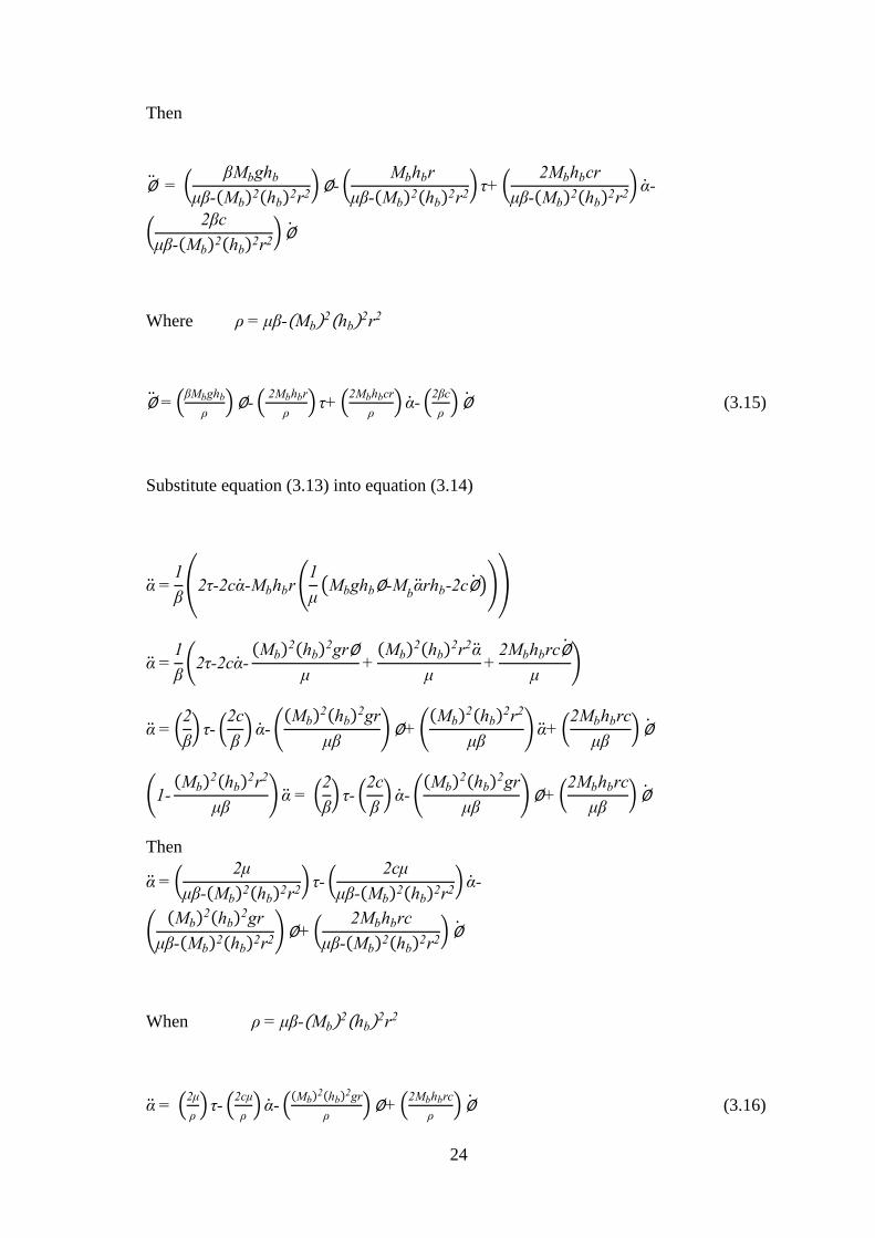
24
Then
∅ = (βMbghb
μβ-(Mb)2(hb)2r2)∅- (
Mbhbr
μβ-(Mb)2(hb)2r2) τ+ (
2Mbhbcr
μβ-(Mb)2(hb)2r2) α-
(2βc
μβ-(Mb)2(hb)2r2) ∅
Where ρ = μβ-(Mb)2(hb)
2r2
∅ = (βMbghb
ρ)∅- (
2Mbhbr
ρ) τ+ (
2Mbhbcr
ρ) α- (
2βc
ρ) ∅ (3.15)
Substitute equation (3.13) into equation (3.14)
α =1
β(2τ-2cα-Mbhbr (
1
μ(Mbghb∅-M
bαrhb-2c∅)))
α =1
β(2τ-2cα-
(Mb)2(hb)
2gr∅
μ+
(Mb)2(hb)
2r2α
μ+
2Mbhbrc∅
μ)
α = (2
β) τ- (
2c
β) α- (
(Mb)2(hb)
2gr
μβ)∅+ (
(Mb)2(hb)
2r2
μβ) α+ (
2Mbhbrc
μβ) ∅
(1-(Mb)
2(hb)2r2
μβ) α = (
2
β) τ- (
2c
β) α- (
(Mb)2(hb)
2gr
μβ)∅+ (
2Mbhbrc
μβ) ∅
Then
α = (2μ
μβ-(Mb)2(hb)2r2) τ- (
2cμ
μβ-(Mb)2(hb)2r2) α-
((Mb)
2(hb)2gr
μβ-(Mb)2(hb)2r2)∅+ (
2Mbhbrc
μβ-(Mb)2(hb)2r2) ∅
When ρ = μβ-(Mb)2(hb)
2r2
α = (2μ
ρ) τ- (
2cμ
ρ) α- (
(Mb)2(hb)
2gr
ρ)∅+ (
2Mbhbrc
ρ) ∅ (3.16)

25
For the DC motor model is considered
From the motor equation
V-Keω=Ldi
dt+Ri
τm-τL=Jmω+bmω
τm=KtKdi
ω=α
KtKdi-τL=Jmα+bmα
Then
τL=τ=KtKdi-Jmα-bmα (3.17)
Substitute equation (3.17) to equation (3.16)
ρα =2μτ-2cμα-(Mb)2(hb)
2gr∅+Mbhbrc∅
ρα =2μ(KdKti-Jmα-bmα)-2cμα-(Mb)
2(hb)2gr∅+2Mbhbrc∅
(2μJm+ρ)α =2μKdKti-(2μb
m+2cμ)α-(Mb)
2(hb)2gr∅+2Mbhbrc∅
Then a new equation will be
α = 1
2μJm+ρ(2μKdK
ti-(2μb
m+2cμ)α-(Mb)
2(hb)2gr∅+2Mbhbrc∅) (3.18)
And substitute equation (3.17) to equation (3.15)
ρ∅ = βMbghb∅-2Mbhbr(KdKti-Jmα-bmα)+2Mbhbcrα-2βc∅
ρ∅ = βMbghb∅-2MbhbrKdKti+2MbhbrJ
mα+(2Mbhbrbm+2cMbhbr)α-2βc∅

26
For this term 2MbhbrJm
α
= 2MbhbrJm
(1
2μJm+ρ(2μKdK
ti-(2μb
m+2cμ)α-(Mb)
2(hb)2gr∅+2Mbhbrc∅))
= 4MbhbrJ
mμKdK
t
2μJm+ρi-
2MbhbrJm(2μb
m+2cμ)
2μJm+ρα-
2Jm(Mb)3(hb)
3gr2
2μJm+ρ∅+
4(Mb)2(hb)
2r2Jmc
2μJm+ρ∅
Then substitute back
ρ∅ = βMbghb∅-2MbhbrKdKti+
4MbhbrJm
μKdKt
2μJm+ρi-
2MbhbrJm(2μb
m+2cμ)
2μJm+ρα-
2Jm(Mb)3(hb)
3gr2
2μJm+ρ∅+
4(Mb)2(hb)
2r2Jmc
2μJm+ρ∅+(2Mbhbrbm+2cMbhbr)α-2βc∅
ρ∅ = (βMbghb-Jm(Mb)
3(hb)3gr2
2μJm+ρ)∅- ( 2MbhbrKdK
t+
4MbhbrJm
μKdKt
2μJm+ρ) i-
( 2MbhbrJ
m(2μb
m+2cμ)
2μJm+ρ+2Mbhbrbm+2cMbhbr) α+ (
4(Mb)2(hb)
2r2Jmc
2μJm+ρ-2βc) ∅
When A = Mbhbr
B = Jm
2μJm+ρ
ρ∅ = ( βAg
r-gMbhbA
2B)∅-(2AKdK
t+4ABμKdK
t)i-
(2AB(2μbm
+2cμ)+2Abm+2cA)α+(4A2Bc-2βc)∅
Then another equation will be
∅ = 1
ρ((
βAg
r-gMbhbA
2B)∅-(2AKdK
t+4ABμKdK
t)i-
(2AB(2μbm
+2cμ)+2Abm+2cA)α+(4A2Bc-2βc)∅) (3.19)

27
The motor model is
V-Keω = Ldi
dt+Ri
Inductance is less than resistance (L<<R).
V-Keω ≈ Ri
Then
i≈V-Keω
R ≈
V
R-
Ke
Rα (3.20)
Substitute equation (3.20) into equation (3.18)
α =1
2μJm+ρ(2μKdK
t(V
R-Ke
Rα) -(2μb
m+2cμ)α-(Mb)
2(hb)2gr∅+2Mbhbrc∅)
α=1
2μJm+ρ(
2μKdKt
RV- (2μb
m+2cμ+
2μKdKtKe
R) α-(Mb)
2(hb)2gr∅+2Mbhbrc∅) (3.21)
Moreover, substitute equation (3.20) into equation (3.19)
θ = 1
ρ((
βAg
r-gMbhbA
2B)∅-(2AKdK
t+4ABμKdK
t) (
V
R-Ke
Rα) -
(2AB(2μbm
+2cμ)+2Abm+2cA)α+(4A2Bc-2βc)∅)
∅ = 1
ρ((
βAg
r-gMbhbA
2B)∅- (
2AKdKt+4ABμKdKt
R) V+ ((
2AKdKtKe
R+
4ABμKdKtKe
R) -
(2AB(2μbm
+2cμ)+2Abm+2cA)) α+(4A2Bc-2βc)∅) (3.22)
3.6 The state space model
If equation of the mechanics of the system is complete, the state space representation are
shown inputs, outputs and state variables. The standard formula of state space shown as
below, y(t) shown by output, x(t) shown by state of the system.
28
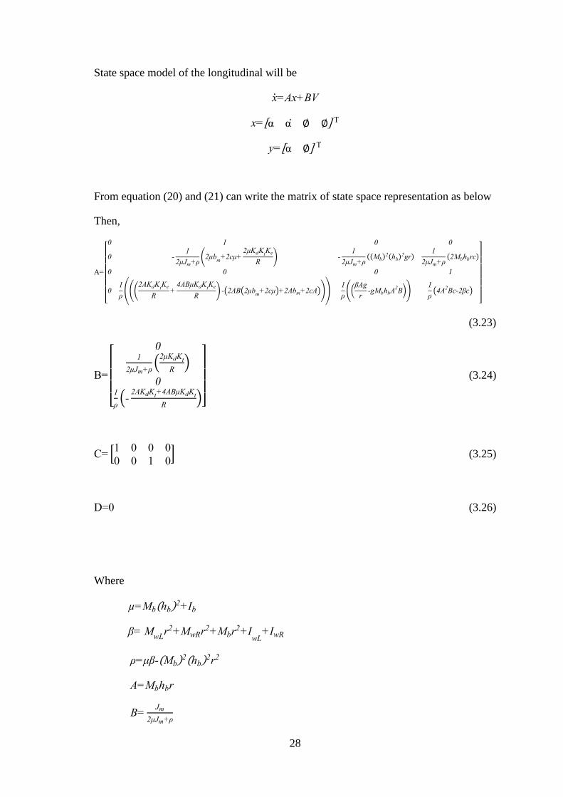
State space model of the longitudinal will be
x=Ax+BV
x=[α α ∅ ∅] T
y=[α ∅] T
From equation (20) and (21) can write the matrix of state space representation as below
Then,
A=
[ 0 1 0 0
0 -1
2μJm+ρ(2μb
m+2cμ+
2μKdKtKe
R) -
1
2μJm+ρ((Mb)
2(hb)2gr)
1
2μJm+ρ(2Mbhbrc)
0 0 0 1
01
ρ(((
2AKdKtKe
R+
4ABμKdKtKe
R) -(2AB(2μb
m+2cμ)+2Abm+2cA)))
1
ρ((
βAg
r-gMbhbA
2B))
1
ρ(4A
2Bc-2βc)
]
(3.23)
B=
[
01
2μJm+ρ(
2μKdKt
R)
01
ρ(-
2AKdKt+4ABμKdKt
R)]
(3.24)
C= [1 0 0 0
0 0 1 0] (3.25)
D=0 (3.26)
Where
µ=Mb(hb)2+Ib
β= MwL
r2+MwRr2+Mbr2+IwL
+IwR
ρ=μβ-(Mb)2(hb)
2r2
A=Mbhbr
B=Jm
2μJm+ρ

29
3.7 Parameter identification
If equation of the mechanics of the system is complete, the state space representation are
shown inputs, outputs and state variables. The standard formula of state space shown as
below, y(t) shown by output, x(t) shown by state of the system.
Table 3.3 The table of constant parameter for balancing
The constant parameter Value Unit
The mass of the body (𝑀𝑏) 5.2 kg.
The mass of the wheel (𝑀𝑤) 0.5 kg.
The high the body (ℎ𝑏) 0.8 m.
The moment inertia of the wheel (𝐼𝑤) 0.0025 kg.m2
The moment inertia of the body (𝐼𝑏) 1.667 kg.m2
The viscosity friction of wheel (c) 0.002 kg.m2/s
The transmission ratio (𝐾𝑑) 51.8
Torque DC constant (𝐾𝑡) 0.0093687 N.m/A
Back EMF constant (𝐾𝑒) 0.9857 Volt/rad/sec
The friction in the DC motor (𝑏𝑚) 0.002 N.m.s/rad
Resistance (𝑅) 10.585 Ω
The moment inertia of the DC motor (𝐽𝑚) 2.2284x10⁻⁶ kg.m2
Gravity (𝑔) 9.8 m/s2
The radius of wheel robot (r) 0.1 m
These parameter were derived from experiments and calculations.

30
3.8 Control algorithms of a Segway-type robot
There are consist of two transfer functions of a Segway-type wheelchair to balance.
Therefore, there are two output or two transfer function of a Segway-type wheelchair
robot system. The first transfer function is the angle of the wheel to changer divided
voltage output and the second transfer function is the leaning angle of the robot to changer
divided voltage output.
In conclusion, the first transfer function is
α
V=
0.0505s2-5.159e-05+1.193
s4+1.155s3-15.59s2-17.96s+2.107
Continuous-time transfer function.
∅
V=
-0.9401s2-1.084s+0.0505
s4+1.155s3-15.59s2-17.96s+2.107
The characteristic equation will be
s4+1.155s3-15.59s2-17.96s+2.107
And the pole of this system is
Figure 3.16 Pole of system
p = 3.9339, -3.9259, -1.2703, 0.1074
31
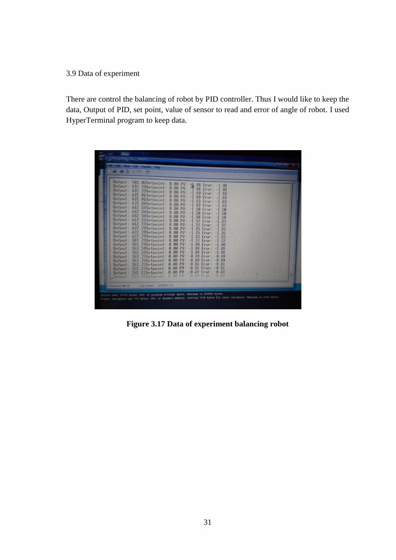
3.9 Data of experiment
There are control the balancing of robot by PID controller. Thus I would like to keep the
data, Output of PID, set point, value of sensor to read and error of angle of robot. I used
HyperTerminal program to keep data.
Figure 3.17 Data of experiment balancing robot

32
CHAPTER 4
RESULTS AND DISCUSSION
This chapter, as the results divided in two parts, Frist, there are simulation results in
Matlab program. I got two transfer function by calculate from state space A, B, C and D
matrixes with many control algorithms. Second, experiment results.is tested balancing
with real a Segway-type wheelchair robot.
State space matrix is
A = [
0 1 0 0
0 -1.1544 -2.1067 1.033e-04
0 0 0 1
0 0.0169 15.5910 -9.0153e-04
]
B= [
0
0.0505
0
-0.9401
]
C= [1 0 0 0
0 0 1 0]
D=0
4.1 Simulation results in Matlab software
Equation (3.20) and (3.21) is used to balance of a Segway-type wheelchair robot the
parameter gain is by error method
Kp = 1000, Ki = 100, Kp = 60
In the Matlab program, there are Matlab Simulink block which can find the leaning angle
of a Segway-type wheelchair robot and leaning rate of wheels of wheelchair robot.
Moreover, control algorithms used PID controller. Figure 4.1 is PID simulation model.
The PID simulation result for balancing shown on figure 4.2

33
Figure 4.1 The PID simulation model
Figure 4.2 The PID simulation result for balancing
From the simulation result in Figure 4.2 the disturbance noise effect on the angle output.
The system angle of robot cannot be zero which its swing around set point. Average
value of the leaning angle of robot is 0.352 rad. In addition, Average value of the learning
angle of wheel robot is 10.038 rad/s
34
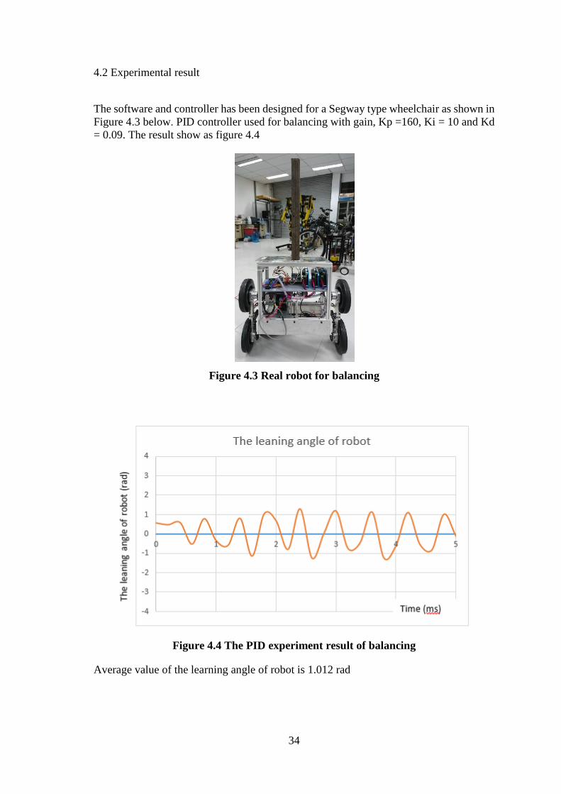
4.2 Experimental result
The software and controller has been designed for a Segway type wheelchair as shown in
Figure 4.3 below. PID controller used for balancing with gain, Kp =160, Ki = 10 and Kd
= 0.09. The result show as figure 4.4
Figure 4.3 Real robot for balancing
Figure 4.4 The PID experiment result of balancing
Average value of the learning angle of robot is 1.012 rad
35
CHAPTER 5
CONCLUSIONS AND FUTURE WORKS
5.1 Conclusions
A Segway-type wheelchair robot is the robot which can balance two wheels. In this thesis,
there are three parts about a Segway-type wheelchair robot. Frist of all, mechanic design
and dynamic model are very importance about the balancing concept. Moreover, all parts,
speed of each motor and the weight of robot are effected on balancing robot also. Second,
electronic design is important also. Moreover, there are using the layout of all electronic
such as Gyroscope & accelerometer sensor, regulator and drive control dc motor. Finally,
PID controller is the control algorithm to balancing the wheelchair robot which A
Segway-type wheelchair robot can be to balance the two wheels.
The result of control consist of two parts; simulation and experiment result. The first one
is simulation result which the dynamic model of a Segway-type wheelchair robot. A
Segway-type wheelchair robot to balance fix by using the Newton Euler and Matlab
program for Simulink the result. The control system selected by PID algorithm. Another,
the experiment result is applied in real system. A Segway-type wheelchair used PID
controller which used to control error of angle of the body robot and used to find position
of right wheel and left wheel for balancing by itself.
In addition, a Segway-type wheelchair robot can be the simulation result that is very good.
The dynamic model provide state space of real robot. Thus, there are two transfer function
to control angle of the body robot and position in rotate of wheels.
5.2 Future works
This thesis, a Segway-type wheelchair robot would like develop to movement, forward,
backward, turn right and turn left by joystick. Some mechanic should have modifies and
implement. For example, motor have to more power and using another algorithm control.
36
REFERENCES
[1] Her-Terng Yau1 , Cheng-Chi Wang2 , Neng-Sheng Pai1 and Ming-Jyi Jang2,
Robust Control Method Applied in Self-Balancing Two-Wheeled Robot,
Taiwan,2009.
[2] M. Baloh, and M. Parent, “Modeling and model verification of an intelligent self-
balancing two-wheeled vehicle for an autonomous urban transportation system,”
Proc. Conf. Comp. Intelligence, Robot. Autonom. Syst., Singapore, 2003.
[3] Vos, D.W. and Von Flotow, A.H.(1999), Dynamics and nonlinear adaptive
control of an autonomous unicycle: theory and experiment, Decision and Control,
1990., Proceedings of the 29th IEEE, pp. 182-187.
[4] Junfeng Wu, Vos, Wanying Zhang and Shengda Wang, A two-wheeled self-
balancing robot with the fuzzy PD control method: theory and experiment.
[5] D. Dubois and H. Prade, “Fuzzy sets in approximate reasoning. I. Inference with
possibility distributions,” Fuzzy Sets and Systems, vol. 40, no. 1, pp. 143–202,
1991.
[6] Segway. Segway - the leader in personal, green transportation. Online, 2013.
http://www.segway.com.
[7] Williams V. & K. Matsuoka, 1991 ‘ Learning to Balance the Inverted Pendulum
Using Neural Networks’, IEEE International Joint Conference on Neural
Networks, vol 1, pp. 214-219.

37
APPENDIX
Appendix A: C code for control a segway-type wheelchair
#include <BNO055.h>
#include <Encoder.h>
#include <DualVNH5019MotorShield.h>
#include <MsTimer2.h>
#include <PID_v1.h>
#include <Wire.h>
#define ENCODER_OPTIMIZE_INTERRUPTS
void loop(void)
imu.readEul();
controlLoop();
//delay(5000);
Serial.print("Setpoint: ");Serial.print(Setpoint);
Serial.print(" ");
Serial.print("PV: ");Serial.print(balanceInput);
Serial.print(" ");
Serial.print("Eror: ");Serial.println(balanceInput);
Serial.print(" ");
Serial.print("Output: ");Serial.print(balanceOutput);