development of advanced instrumentation for … environmental prediction" ... variability in...
TRANSCRIPT
Development of advanced instrumentation for operational oceanography
G. Zappalà CNR IAMC, Messina, Italy
Abstract
Operational oceanography is an applied science requiring new instrumentation to perform cost effective surveys. The use of XBT probes from Voluntary Observing Ships is a good way to obtain temperature profiles, but it is limited by the cost of the probes and of the operators on board. An automatic multiple XBT launcher was developed, to work unattended and be recharged by a crew member, without the need for a technician. Keywords: operational oceanography, marine monitoring, XBT, voluntary observing ships.
1 Introduction
The assessment of environmental conditions requires a series of measurements, with a good spatial and temporal resolution. The high cost and limits of traditional oceanographic surveys stimulate the use of new techniques to obtain a proper coverage. So, traditional moorings and oceanographic cruises are complemented with autonomous devices (e.g. drifters and gliders) and with the use of "ships of opportunity". In the framework of the EU funded "Mediterranean ocean Forecasting System Toward Environmental Prediction" (MFSTEP), several experiences were performed both in the use and in the development of advanced instrumentation. Started in 1999 as a part of the "Mediterranean ocean Forecasting System Pilot Project" (MFSPP), a Voluntary Observing Ship (VOS) program is still collecting temperature XBT profiles along seven Mediterranean transects, designed to study, in each of the sub-basins (the Algero-Provençal, the Tyrrhenian, the south Adriatic, the Ionian and the Levantine), the variability of the main circulation features [1]. Although less expensive than dedicated oceanographic cruises, the
© 2007 WIT PressWIT Transactions on Modelling and Simulation, Vol 46, www.witpress.com, ISSN 1743-355X (on-line)
Computational Methods and Experimental Measurements XIII 841
doi:10.2495/CMEM070821

use of commercial ships to launch XBT probes requires however the presence of one or more technicians on board the ship, with the related costs. In order to obtain cheaper operations, an automatic device was designed, to launch unattended up to eight probes, easy enough to be recharged by a member of the crew.
2 Materials and methods
An XBT probe has the shape of a small missile, contained in a plastic canister with an overall length of 36 centimetres and external diameter of 7 centimetres; its weight is about 1200 grams. The temperature sensor is a precision thermistor enclosed in the lead nose; the electrical wire to connect it to the measuring system is contained in two spools, one in the plastic body of the probe and the other one in the canister, that also hosts on its back the electrical connections towards the data acquisition system. Traditional use of XBT (expendable bathy-thermograph) probes implies the presence of a technician on board the ship to manually perform the "launch". The plastic canister is inserted in a hand-held "gun"; pressing the trigger the probe is released; while the probe falls into water, the wire inside it starts unreeling. The wire unreels also from the spool in the canister, compensating the movement of the ship and allowing the probe to freefall from the sea surface down to several hundred meters depth. A data acquisition board connected to a computer controls the measurement; when the wire breaks, the profile is completed and the system can be prepared for another launch. The nominal accuracy of the probe is 0,1°C. The depth is estimated as a function of time, using a formula of the kind Z(t)=At-Bt2. Acquired data can be transmitted using satellite or GSM-GPRS modems.
3 The automatic multiple launcher
The new system is an integrated set of mechanical and electronic hardware and software programs offering the maximum of flexibility.
3.1 The mechanical hardware
Heart of the mechanical hardware is the launch tube, built in AISI 316 steel, in which the probe is fitted with its envelope. An upper cap, holding the electrical connections of the probe, closes the launch tube; opening the lower door the probe is released and falls into seawater. Two pneumatic cylinders control the door: a small one keeps it closed acting as a safety lock also in case of pressure loss, a bigger one moves it. In the actual MFS-VOS design, the system assembles on a frame eight launch tubes with their pneumatic actuators (fig. 1). A small compressor supplies compressed air to the system, keeping a reserve of 5 litres at 6 bar; a filtered pressure regulator is mounted to prevent damages to the pneumatic system.
© 2007 WIT PressWIT Transactions on Modelling and Simulation, Vol 46, www.witpress.com, ISSN 1743-355X (on-line)
842 Computational Methods and Experimental Measurements XIII

Figure 1: A close-up view of two launch cylinders with the pneumatic actuators.
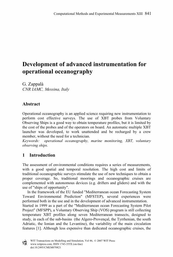
Two versions of the launcher were built: the first to work hanged outboard the ship, the second to stay inboard, on a deck. Fig. 2 (left) shows the "outboard" version, and (right) the inboard one, mounting a funnel with a pipe to drive probes outboard.
© 2007 WIT PressWIT Transactions on Modelling and Simulation, Vol 46, www.witpress.com, ISSN 1743-355X (on-line)
Computational Methods and Experimental Measurements XIII 843
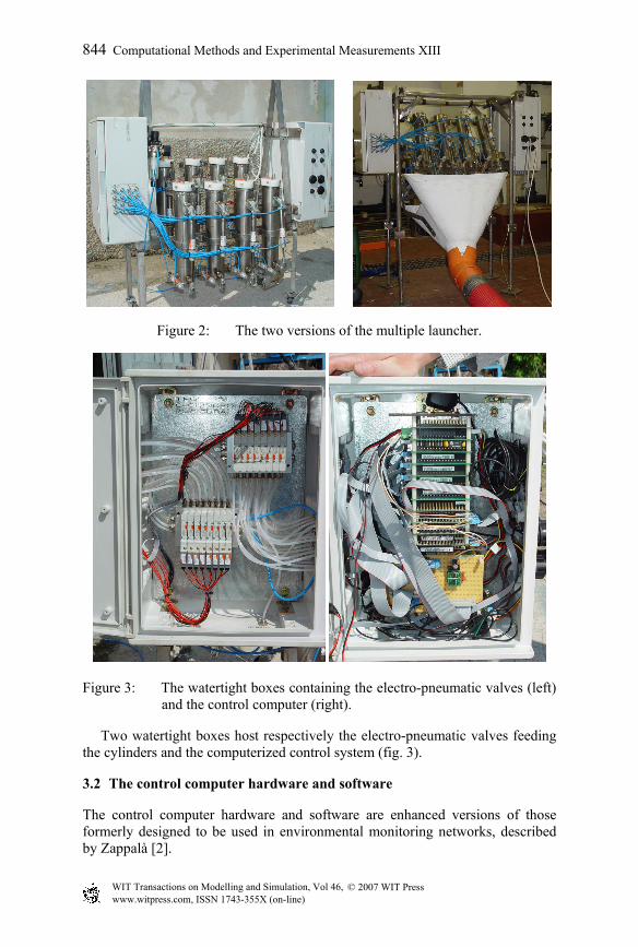
Figure 2: The two versions of the multiple launcher.
Figure 3: The watertight boxes containing the electro-pneumatic valves (left)
and the control computer (right).
Two watertight boxes host respectively the electro-pneumatic valves feeding the cylinders and the computerized control system (fig. 3).
3.2 The control computer hardware and software
The control computer hardware and software are enhanced versions of those formerly designed to be used in environmental monitoring networks, described by Zappalà [2].
© 2007 WIT PressWIT Transactions on Modelling and Simulation, Vol 46, www.witpress.com, ISSN 1743-355X (on-line)
844 Computational Methods and Experimental Measurements XIII
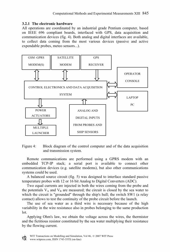
3.2.1 The electronic hardware All operations are coordinated by an industrial grade Pentium computer, based on IEEE 696 compliant boards, interfaced with GPS, data acquisition and communication devices (fig. 4). Both analog and digital interfaces are available, to collect data coming from the most various devices (passive and active expendable probes, meteo sensors...).
Figure 4: Block diagram of the control computer and of the data acquisition
and transmission system.
Remote communications are performed using a GPRS modem with an embedded TCP-IP stack; a serial port is available to connect other communication devices (e.g. satellite modems), but also other communications systems could be used. A balanced source circuit (fig. 5) was designed to interface standard passive temperature probes with 12 or 16 bit Analog to Digital Converters (ADC). Two equal currents are injected in both the wires coming from the probe and the potentials VA and VB are measured; the circuit is closed by the sea water to which the circuit is "grounded" through the ship's hull; the switch SW1 (a relay contact) allows to test the continuity of the probe circuit before the launch. The use of sea water as a third wire is necessary because of the high variability in the wire resistance also in probes belonging to the same production lot. Applying Ohm's law, we obtain the voltage across the wires, the thermistor and the fictitious resistor constituted by the sea water multiplying their resistance by the flowing current.
CONTROL ELECTRONICS AND DATA ACQUISITION
SYSTEM
GSM -GPRS
MODEM(S)
GPS
RECEIVER
POWER
ACTUATORS
MULTIPLE
LAUNCHER
OPERATOR
CONSOLE
LAPTOP
PC
SATELLITE
MODEM
ANALOG AND
DIGITAL INPUTS
FROM PROBES AND
SHIP SENSORS
© 2007 WIT PressWIT Transactions on Modelling and Simulation, Vol 46, www.witpress.com, ISSN 1743-355X (on-line)
Computational Methods and Experimental Measurements XIII 845
B
Rsea
A
Rwire1 Rwire2
Rthermistor
I1 I2
Rballast Rballast
Vsea
Vw1 Vw2Vth
B
Ax 1
x 1
x 2to ADC
Sw1
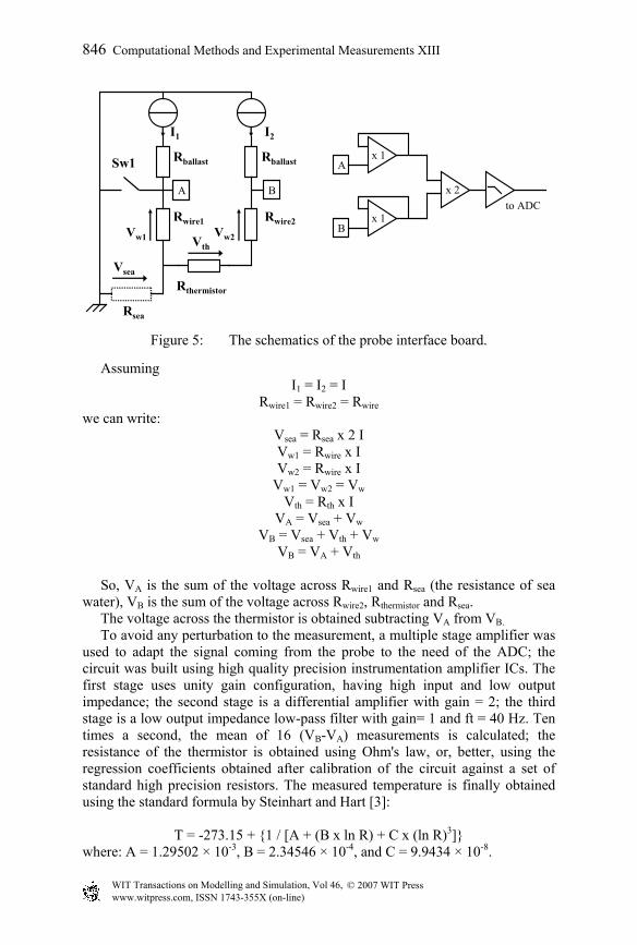
Figure 5: The schematics of the probe interface board.
Assuming I1 = I2 = I
Rwire1 = Rwire2 = Rwire we can write:
Vsea = Rsea x 2 I Vw1 = Rwire x I Vw2 = Rwire x I
Vw1 = Vw2 = Vw Vth = Rth x I
VA = Vsea + Vw VB = Vsea + Vth + Vw
VB = VA + Vth
So, VA is the sum of the voltage across Rwire1 and Rsea (the resistance of sea water), VB is the sum of the voltage across Rwire2, Rthermistor and Rsea. The voltage across the thermistor is obtained subtracting VA from VB. To avoid any perturbation to the measurement, a multiple stage amplifier was used to adapt the signal coming from the probe to the need of the ADC; the circuit was built using high quality precision instrumentation amplifier ICs. The first stage uses unity gain configuration, having high input and low output impedance; the second stage is a differential amplifier with gain = 2; the third stage is a low output impedance low-pass filter with gain= 1 and ft = 40 Hz. Ten times a second, the mean of 16 (VB-VA) measurements is calculated; the resistance of the thermistor is obtained using Ohm's law, or, better, using the regression coefficients obtained after calibration of the circuit against a set of standard high precision resistors. The measured temperature is finally obtained using the standard formula by Steinhart and Hart [3]:
T = -273.15 + {1 / [A + (B x ln R) + C x (ln R)3]} where: A = 1.29502 × 10⁻³, B = 2.34546 × 10⁻⁴, and C = 9.9434 × 10⁻⁸.
© 2007 WIT PressWIT Transactions on Modelling and Simulation, Vol 46, www.witpress.com, ISSN 1743-355X (on-line)
846 Computational Methods and Experimental Measurements XIII

The constants were determined empirically from laboratory tests of XBT thermistors [4].
3.2.2 The software A local and a remote control programs were developed, able to manage 96 launch events. Launch options are: • northern than a defined latitude • southern than a defined latitude • eastern than a defined longitude • western than a defined longitude • far from a previous launch • at GPS time • at PC time Collected data are locally stored and can be transmitted as e-mails. The local control program was written in Microsoft Compiled Basic v. 7.1 and runs in Datalight DOS environment. Assembly language routines are used to manage the Analog to Digital Converter. This program, executed on the launcher control computer, is able to control all the launcher functions, i.e. real time and position acquisition, comparison against set points-times, launch, data acquisition and transmission, ancillary functions. Every hour, a “sequence manager” starts a macro-command sequence, that can be different for each time and is remotely reprogrammable; new releases of the software and of the sequences are uploadable to the station without suspending its normal activity. The macro-commands enable to manage the data acquisition and transmission, the mission programming, the station hardware and the measuring instruments. The entire system can be connected to a computer (local laptop or remote desktop), in order to use a remote control program (fig. 6), written in Microsoft Visual Basic, running in Windows environment. This program enables to set up all the launcher functionalities, prepare launch event sequences, transfer files to and from the launcher, and, if needed, to take control of all the launcher operations, including the time-position acquisition and comparison.
4 Tests
The automatic multiple launcher was tested in laboratory and during two short cruises. The in situ tests were performed in March 2006 using the Italian Hydrographic Institute vessel Magnaghi and in June 2006 with the ENEA boat S. Teresa, in the Ligurian Sea – North western Mediterranean. During these tests, data was recorded with the multiple launcher to verify the efficiency of the whole system (hardware and software), and, for comparison, XBT probes were launched with a standard Sippican system (hand launcher LM 3A, MK21 read-out card). Figure 7 shows some profiles obtained by the multiple launcher. Temperature values measured with reference systems demonstrate the high quality of the multiple launcher profiles.
© 2007 WIT PressWIT Transactions on Modelling and Simulation, Vol 46, www.witpress.com, ISSN 1743-355X (on-line)
Computational Methods and Experimental Measurements XIII 847
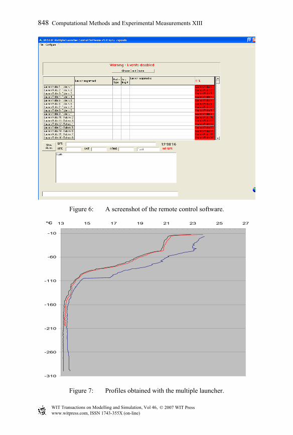
Figure 6: A screenshot of the remote control software.
-310
-260
-210
-160
-110
-60
-10
13 15 17 19 21 23 25 27°C
Figure 7: Profiles obtained with the multiple launcher.
© 2007 WIT PressWIT Transactions on Modelling and Simulation, Vol 46, www.witpress.com, ISSN 1743-355X (on-line)
848 Computational Methods and Experimental Measurements XIII

5 Discussion and conclusions
Figure 8 shows the multiple launcher installed on the Magnaghi ship, assuring safety to operators and undisturbed operations. The use of a multiple launcher improves the cost effectiveness of an operational observing system. Working in the Mediterranean Sea with commercial ships, it is necessary to launch a probe every 20-30 minutes to obtain a good spatial resolution of the mesoscale phenomena on sections several hundreds of miles long, lasting up to 24-36 hours. So, using the manual launcher, at least two technicians are needed, with a cost up to 2000 USD for each travel; using the automatic launcher, it is possible to avoid this cost, or at least halve it, engaging one person only. The small number of electric and mechanic components reduces the risks of malfunctions; the remote control capability enhances the flexibility of the instrument and allows real time operations. The system proved its reliability and is open to further developments and improvements to be used with other expendable probes (XCTDs, T-FLAPs...).
Figure 8: The multiple launcher installed on the deck of the Magnaghi ship.
Acknowledgements
The activity was funded in the frame of the MFSTEP project, 5th EU FP. The Author acknowledges the support provided by N. Pinardi and G. Coppini. The work of technicians during these years has provided the necessary information for the design. The Author thanks G. Manzella and F. Reseghetti for the useful suggestions and A. Baldi and F. Conte from ENEA, for their technical support.
© 2007 WIT PressWIT Transactions on Modelling and Simulation, Vol 46, www.witpress.com, ISSN 1743-355X (on-line)
Computational Methods and Experimental Measurements XIII 849

References
[1] Pinardi, N., Allen, I., Demirov, E., DeMey, P., Korres, G., Lascaratos, A., LeTraon, P.Y. Maillard, C., Manzella, G., Tziavos, C., The Mediterranean ocean Forecasting System: first phase of implementation (1998 - 2001). Ann. Geophys., 21, pp. 3-20, 2003.
[2] Zappalà, G.: A software for environment monitoring networks, Proc. of the 10th Int. Conf. On the Development and Application of Computer Techniques to Environmental Studies, eds. G. Latini, G. Passerini & C.A. Brebbia, WIT Press: Southampton, pp. 3-12, 2004.
[3] Steinhart, J. S., Hart, S. R., Calibration curves for thermistors, Deep-Sea Research 15, pp. 497-503, 1968.
[4] Georgi, D. T., Dean, J. P., Chase, J. A., Temperature calibration of expendable bathy-thermographs, Ocean Engineering, 7, pp. 491-499, 1980.
© 2007 WIT PressWIT Transactions on Modelling and Simulation, Vol 46, www.witpress.com, ISSN 1743-355X (on-line)
850 Computational Methods and Experimental Measurements XIII