development of aircraft windshields to resist impact … tdc report 74.pdf · test equipment and...
TRANSCRIPT

DEVELOPMENT OF AIRCRAFT WINDSHIELDS TO RESIST IMPACT
WITH BIRDS IN FLIGHT PART II
INVESTIGATION OF WINDSHIELD MATERIALS AND METHODS OF
WINDSHIELD MOUNTING
BY
Pell Kangas and George L Plgman Amxaft Development Dwlsmn
Techmcal Development Report No 74
CIVIL AERONAUTICS ADMINISTRATION
TECHNICAL DEVELOPMENT
INDIANAPOLIS, INDIANA
February 1950
-
TABLE OF CONTENTS
Page
SUMMARY . a . . . . . . . . 1
INTRODUCTION. . . . . . 1 TEST EQUIPMENT AND METHOD OF TEST ~ a. 2 DESCRIPTION OF PANEL TYPES . . . , . 7 TEST RESULTS AND DISCUSSION . . . . . 9 SPECIAL PROBLEMS ASSOCIATED WITH IMPACT RESISTANT WINDSHIELD DESIGN 32 ADDITIONAL STUDIES REQUIRED . . 36 CONCLUSIONS 36
TABLE INDEX
I Summary of Impact Tests of Type 1 WIndshIeld Panels Conslstlng of SlngIe Pane with RIgId or Clamped Edge Type of Mountmg 39
II Summary of Impact Tests of Type 2 Wmdshleld Panels Conslstmg of Smgle Pane WI+& Flexible Bolted Edge Type of Mountmg . . . . . 40
III Summary of Impact Tests of Type 3 Wlndshleld Panels Conslstlng of Double Pane Assembly wtth RIgId or Clamped Edge Type of Mountmg . . .,. 41
IV Summary of Impact Tests of Type 4 Wmdshleld Panels Conslstrng of Double Pane Assembly with Flextble Bolted Edge Type of Mountmg m Rear Pane . 42
V Examples of Impact Test Results of Amcraft Wmdshlelds Arranged Accordmg to Type of Failure . . . . . 43
VI Recommended Insert Thickness and Mountmg Bolt Size and Spacmg for Varmus Polyvmyl Butyral Thxcknesses Used ln Awcraft Wmdshleld Panes 44

Manuscript Received, November 1947
This report has been presented before the iollowmg
Society of Automotive Engmeers, NatIonal Air Transport Engmeermg Meetmg
Kansas City, MO , December 3, 1947

DEVELOPMENT OF AIRCRAFT WINDSHIELDS TO RESIST IMPACl WITH BIRDS IN FLIGHT
Part II
INVESTIGATION OF WINDSHIELD MATERIALS AND METHODS OF WINDSHIELD MOUNTING
SUMMARY
Impact tests of wmdshxld mstallatmns were carned out by means of a compressed- al= catapult, wh,ch p r 0, e c t s freshly k,lled bird c a r c a s s e s at velocltxs equvalent to alrcraft flqght speeds as great as 450 mph
Impact tests of varmus wIndshIeld mate reals and types of panel constructmn were conducted with panels mounted in both a standard laboratory test frame and In actual cockplt structures submltted for test by varmus manufacturers and air line operators Twoprmc~paltypes of wmdshleld mstallatmn were tested The flat double-pane warm air de-lcmg type won d s h 1 e 1 d was mltlally the primary type consIdered With the Intro- ductmnof electrically heatedpanels, mcorpo- r atlng a transparent electrIca conductmg illm, the smgle-pane type was mcluded m the tests
It 1s shown that the prxnary factor af- fectmg Impact strength of lammated wmd- shield panels themselves 15 the thickness of the plastx Interlayer The most xnportant factor, concermng the mstallatmn of the panels In the cockpits, IS the method of attachment to the al* frame structure
The test results show that the most eiflclent type of wIndshIeld panel constructlon as concerns high mnpactstrength 1s the laml- nated type with thick polyvmyl butyral plastic Interlayer, with an extended flexible plastic edge mcorporatmg a metal x,sert bolted to the frame structure A glass-plastxc panel of this type with 0 125 ln polyvmyl butyral plastic mterlayer, with an angle of slope of 41 ” andplastlc temperature of 80” F, resists penetratmnof a 4-lb carcass atvelocltles up to 280 mph when tested in the standard steel frame Slmllarly, a panel with 0 25-m polyvmvl butyral plastlcmterlayer resxsts penetratlonatvelocltles up to 440 mph Panels tested m arcraft cockplt structures give
lower penetratmn velocity values because of general g r e ate r r,gld,ty of the supportmg structure and less uniform edge support
Further data are g lven I,, connectlo,, with wmdshleld frame design, edge mountmg problems, strengthof side and other wmdows, optlcal and thermal characterlstlcs of panels, spllnterlngproblems,effectofpanel mounting angle, effect of locatmn of Impact, and other general design problems
INTRODUCTION
The general problem of frequency and hazards of colllslon of alrcrait with birds I* flight, with partzcular reference to damage of wmdshleld areas, 1s presented separately m Part I of this report 1
In this, Part II, are g,ven the results of tests concerned with the development of nn- pact resIstant wmdshwlds, and basic Infar- matmn applxable to their desqn Part II 15 I” the nature of a progress report, and xv,11 be followed In the future by addItIona reports
The tests coxered in the present report were mltlated in 1942 by the Clvll Aeranautlcs Admmlstratlanas part of adevelopment pro- gram lookmg to the mcreasmg of the Impact resistance of alrcraft wmdshleldi to provide protectlon agamst colllslon with birds in flight This program was started as a result of requests from varmu5 air tarrle* oper- ators, and from regulatory badles wIthIn the Admmlstratmn, which arose a5 a result oi aIrplane colllslans wIthlarge birds which had occurred in the precedq several years
‘Pell Kangas and George L Plgman, “Development of AIrcraft WIndshIelds to Res& ImpactwIth Birds m Flight,” Part I, Technl- cal Development ReportNo 62, January 1949

Wmdshleld te > t,ng in connectmn with th,s program was started in July, 1942, at the laboratories of the Westmghouse E I e c t r 1 c andManufacturlng Company, EastPlttsburgh, Pennsylvanm This work was c a r r le d out underdlrectClvllAeronaut,csAdmlnlstratlon supervls,or+ bututIlIzed Westmghouse persow nel, facxlltles, and s p e c 1 a 1 test equpment developed for the CAA by the Westmghouse Company The work at Eilst Pittsburgh was terminated in November 1943
InFebruary 1945, constructmnof wmd- s hle Id test faclhtles was completed at the CAA Expe r,mental Statmn, Indww.pol,s, Indmna, and the test program was resumed This p r o g ram contmued through 1945 and a portmn oi 1946 Durmg the remainder of 1946 and I,, 1947, only lxnlted tests other than for prwate manufacturers we r e conducted, andno apprecmble progress was made 1n the general test program
The present report covers results and conclusions o btalne d in this mvestlgatmn from the txne test work was started in 1942 until the present time Some test results were publIshed in Jan u a r y 1945, and the present report reviews the data presented in this earlier publlcatmn The data presented in the present report are still mcomplete in many respects, and It 1s planned to complete such data durmg the future course of the program
The purposes of the test program have beento secure practxaland basx mformatlon far use in the design of impact resistant wndshlelds, to a 1 d wmdshleld and alrcraft manufacturers in the development and appll- catmnof unproved designs, and to coordmate knowledge of optxal. de-lung, andotherwmd- shleldcharacterlstlcs with xnpactres~stance to arrive at optrnum design requrements
The authors wish to acknowledge with apprecmtmn the cooperatmn of the followmg a,rcraft manufacturers, air lmes, and glass and plastic manufacturers for pro- v~d,ngwndsh~eld mstallatmns and assocmted matenals, numerous Ideas and useful sug- gestmns, and permlssmn for use in this re-
2George L Plgman, “Impact-ResIstant Wmdshwld C o n s t r u c t 1 o n , I’ AeronautIcal Engmeermg Review, Vol 4. No 1, January 1945
2
port of data obtained from tests on actual cockplt structures
Ameruzan AlrImes Beech AIrcraft Corporatmn Boemg AIrcraft Company Consalldated Vultee Axcraft Corporatmn Curtlss-Wright Corporatmn, A,rplane Dl”lSlOn Douglas Alrcraft Company. Incorporated E I du Pant de Nemours & Company, Plastics Dlvlslon The Glenn L Mar tm Company Grumman Alrcraft Engmeermg Company Llbbey-Owens-Ford Glass Company Lockheed Axcraft Corporatmn Pittsburgh Plate Glass Company Rohm k Haas Company Umted Air Lmes
TEST EQUIPMENT AND METHOD OF TEST
Impact Tests In the conduct of the wmdshleld Impact
tests a compressed-air gun 1s used to pro- ,ect bird carcasses at the wmdshleld panel This gun 1s shown in Fig 1 Gun barrels from three to eight mches mslde dmmeter areused. so thatblrdcarcasses fromapproul- mately 1 to 16 pounds weight may be pro,ected at any predetermmed velocity to a maxxnum of about 450 mph
The chlckens and turkeys used I,, the testsare kllled by electrocutmn ,ust prmr to the test, and are fltted mto a light cloth bag for msertmn in the gun Bird carcasses are used for the tests be c a u s e of the extreme dlfflculty and the uncertamty mvolved x, ob- talnmg a substitute type of pro,ectlle whxh ~111 possess elastic characterxstlcs identical to a real carcass durmg high speed Impact, andbecause bird carcasses have been found to provide reproducible test results
The electrocutmnprocess IS ut&zed m preparmg the carcass for test ln order to re- tam ,ts characterlstlcsas nearly as possible to those of the lwmg condltmn
After leavmg the muzzle of the gun, the carcass breaks a set of fine steel wues, shown in Fig 2, which are placed across its path for velaclty measurmg purposes TWO wires of the set are spaced wltb a 5-foot separatmn, and are connected to a galva- nometer osclllograph which lndlcate s the correspondmg tnne Interval Two other wires

Fig. 1 Compressed Air Gun
of the set, also with a 5-foot separation, are
connected to a direct-reading chronoscope.
Thus two independent measurements of the
carcass velocity are obtained. These instru-
ments are in the control room shown in
Fig. 3. The carcass velocity obtained with the
gunis predeterminedin terms of the gun air-
tank pressure, and may be predicted within
approximately *lO per cent. The point of
impact of the carcass on the windshield
structure is predetermined within about a
1 -in. radius by bore-sighting the gun upon the
point of the structure which is to receive the
impact. The windshield panels are mounted in
various t y p e s of supporting structures for
test. In most of the tests, in which the main
purpose was to determine only the panel
s t r e n g th and panel impact characteristics

Fig. 2 Windshield Test Chamber
under v a r i o u s conditions, a standard steel
frame structure was used. This structure,
shown in Figs. 2 and 4, was adopted because
of its simple constructionand ease of repair,
and was intended to have approximately the
same elastic characteristics and rigidity as
an average windshield f r ame structure on
large aircraft. As will be shown later, this
steel frame structure is actually less rigid,
and apparentlyproduced lower impact forces
in the panel, than a normal cockpit structure
of large aircraft.
Numerous tests have been carried out
utilizing a p o r ti o n of the airplane cockpit
structure for mounting the t e s t windshield
panels. Tests of this nature have been con-
ducted in cooperation with various aircraft
manufacturers and air c a r r i e r operators,
and have included the Douglas Models DC-4
and DC-6, Lockheed Model 49, Curtiss-
WrightC-46-A and C-46-E. United Air Lines
DC-3 andDC-4, Beechcraft Models D185
and 34, MartinModel 202, Boeing Model 377,
Grumman G73, Consolidated V ul t e e Model
240, and others. In such tests the entire
cockpit s t r u c t u r e was used, including the
structure above the approximate centerline
of the fuselage and extending forward from
the first b ul k he ad at the rear of the pilot
compartment to a point several feet in front
of the windshield. In Fig. 5 is shown a typical
cockpit structure, in position for impact test
in the test chamber. Fig. 5 also illustrates the method of support c o mm o n 1 y used for
such structures in the test chamber. The structure is clamped rigidly to the floor of
the test chamber, and supported against the
rigid rear wall by means of wood braces

Fig. 3 Impact Test Control Room
behind each of the main longitudinal structural
members.
Measurement of panel temperature at
the time of testwas obtained by thermocouples
placed in close contact with each face of the
panel Panel heating to obtain desired temper-
atures was accomplished by means of heat
lamps, and cooling was obtained by immersion
of the panel in water of the desired temper-
ature, or by cooling of the entire test chamber.
High-speed motion pictures we r e ob-
tained of many of the windshield p an e 1 s at
the instantof impactas anaid in understanding
the nature of the impact and the mechanism
of the failures. For this purpose a General
Radio Type 651 -AC high-speed motion picture
camera was used, and was operated at a
speed of lOOO-frames per second.
Optical Tests
0 p t i c a 1 deviation tests of windshield
panels we r e made by photographing a grid
through the panel bymeans of a camera
e cl u i p p e d with a long focal length lens, as
shownin Fig. 6. The lens axis of the camera
was placed perpendicular to both the plane of
the panel and the plane of the grid. The dis-
tance between the windshield p an e 1 and the
grid was arranged so that the l-in. grid
spacings corresponded to ten minutes of arc
deviation of the line of sight.
A photograph of the grid was taken
t h r o u g h the windshield panel, and then the
panel was removed and a second photograph
was taken of the grid upon the same photo-
graphic negative. Measurement of grid line
displacements on an e n 1 a r g e c’ print of the

/
\
\
c
\
/
Fig 4 Standard Steel Frame and Supportmg Structure For Wmdshleld Test Panels

Fig. 5 Typical Cockpit Section in Position for Impact Tests
CAMERA WITH TELEPHOTO LENS
RIGID STAND
FOR HOLDING WINDSHIELD PANE
Fig. 6 Schematic View of Arrangement of Equipmel
Measurements of Windshield Panes nt Used in Making Optical Deviation
NOTE: GRID IS COMPOSED
OF I-INCH SOUARES
negative permits determination of the devi- DESCRIPTION OF PANEL TYPES ationat all points of the panel. Measurement
of grid line slopes provides rates of change
of deviation. A large va r i e ty of different types of
windshield panel construction, materials, and

Fig 7 Type I Wmdshleld Panel Single
Pane With RIgId or Clamped Edge Type of Mou”t,“g
arrangementswere lncludedinthe tests The var,ous types may be s e p a rate d Into four pnnapal classlflcatlo”s
(1) Single-pane lnstallatmns with rlgld or clamped edge mounting (2) S,“gle-pane ~“stallatmns with flexible bolted edge mounting (3) Double-pane lnstallatlons havmg rear pane with rlgld edge. (4) Double-pane ,“stallat,o”s hawng rear pane with flexible bolted edge mountmg
Fig 8 Type II Wlndshleld Panel Single Pane With Flexible Bolted Edge Type of Mou”t,“g
Fig 9 Type III Wlndshleld Panel Double
Pane With RIgId or Clamped Edge Type of Mou”t,“g
v a r 10 us typIca lnstallatlons repre - sentmg each of the four classlflcatmns are show” schematically I” Fqs 7 to 10 A de- talled descrlptmn of prmc~pal varlatmns of

9
F’lg IO Type IV Wmdshleld Panel Double Pane With Flexible Bolted Edge Rear Pane Type of Mountmg
each type ,ncl ude d I” the tests 1s given 1” Tables I to IV
It ~111 be seen from these tables that a large va r 1 e ty of panels have been tested, mcorporatmg v a r 1 o u s combmatmns of an- nealed. se”,,-tempered and full-tempered glass, polyvmyl butyral, methyl methacrylate, and cellulose acetate In the mterest 01 brevity. the term polyvmyl butyral ~111 be at trnes referred to as butyral The panels have bee n tested I” va r I o us types of mountmg structures, and with conslderable varmtmn I” details of constructmn
Included I” the types of panels shown mFqs 7 to 10, and described I” Tables I and II, are panels used ia r corner clear- vls1on wmdows, or for added wmdows above or below the wmdshleld proper, I” various pract1w.l l”stallatlo”s
TEST RESULTS AND DISCUSSION
I mpact Resistance of Wmdshuzld Panes The penetratmn velocity, or velac,ty of
bird carcass of speclfled weight which ~111 barely cause iallure of the wmdshwld panel or mxnedmte supporting structure and perm,t portmns of the carcass to pas s through, IS showni” Tables I to IV as determmed by test for each type and varmtmn of wmdshwld panel constructmn The angle of slope, temperature. and other nnportant condltmns of each test are also show”
Each value of penetratmn velocity given I” Tables I to IV 1s generally based on three to four mdlvldual tests. The fmal value of penetratmnveloclty taken I,, each case 1s the medmn value be tw e e n the highest velocity where no penetration 1s obtaIned and the Iowestvelocltywhere penetratm” 1s obtamed
Ideally, each value of penetratmn ve- loclty should be based upon a large number of tests, and should be take” as the upper lmxt of a band of velocltles which cause no penetratlo” However, the expense and compllcatmn of each test, and the practxal lack of need for extreme preclsux, x, the fmal test results, Im,lt the number ai mdlvldual tests which can be conducted Var1atmn I” mdlvldual test results 1s caused by uncontrol- lable varlatmn I” the properties of the test specimens. the attltube and elastx charac- terlstlcs of the bird carcass, and the point of contact of the carcass on the test panel The magnitude of error ,n the values of penetratm”

10
velocity given m Tables I to IV IS estm-,ated to be a max,mum of about fl0 per cent
The slgnlflcant facts shown by the data given in Tables I to IV x, relation to the rel- atlve m,pact strength of va r 10 us types and arrangements of wmdshleldpanels are brlefly as follows
(1) The general type of pane whlchprovldes the greatest unpact strength, when com- pared upon the basis of equal weight with other types of pane construction, IS the lammated ty p e pane wxth thick polyvmyl butyral p 1 a s t 1 c mterlayer and with the flexible plastic edge bolted to the frame structure (2) The thxkness of a pane of one type c0nstruct10n s t r 0 n g 1 y mfluences mlpact strength However, r, a lammated glass- plastx panel with extended plastic edge. the thickness of the tempered glass faces has little effect on nnpact strength wlthn, reasonable lmuts, and the butyral plastx Interlayer thickness has predommanteffect (3) Anopt1mumtemperature ardplast1c1zer contentexlstformaxlmum nnpact strength of all panels in whxh p 1 a s t I c materials conbrlbute appreclablyto the strength This e f f e c t 1s very pronounced III lammated. extendedplastx edge type panes where the plastx prov,des the la r g e portmn of the xnpact strength of the pane (4) In a double-pane arrangement. where a relatively thmfrontpane with good the rmal transmlssloncharacterlstlcs 1s used, the front pane contrlbutes little to the imp a c t strength of the comblnatmn. The type of front pane, wlthln the lrmts pernutted by the thermal requirements, 1s of little xnportance from the Impact stand- po1nt (5) The more snnple andunlform mountmg p o s s 1 b 1 e for a single-pane mstallatlon appears to compensate for any small loss ,n strength associated with the absence of the front pane
(6) The angle of nnpact upon the wmdshleld pane has great effect upon , t s nnpact strength, I,, general agreement with that expectedfromcanslderatlonof varlatlon of force and veloaty components with angle (7) The general r,gld,t> and e ne r gy ab- sorbmg charactprlstlcs of the wmdshleld supportmg s t T u c t u r e have canslderable efiect upon the stru,gth pxhlbltpd by the
winds hle Id pane. A structure whxh 1s hlghlyelastlc,orwhlchundergoesmoderate bucklmg, apparently causes lower forces to develop in the pane, with resultant de- layed fallure (8) Impact upon sloped wn-,dshwld panes 1s more severe for locatlons close to the aft edges or corners of the pane (9) 51ze and shape of wmdshleld pane have little effect upon imp a c t strength over a conslderable range
These various facts revealed by the data are discussed more completely hereln
Type of Panel Constructmn The evident superlorlty in the unpact
strength-we 1 g h t relatmnshlp of the type of pane mcorporatmg g 1 as s faces and a th,ck polyvmyl butyral p 1 a s t I c mterlayer, which extends beyond the glass edges on all sides for boltmg to the mountmg frame, was demon- strated early II, the test program Ths type of construction has appeared so advantageous throughout the t e s t program that the large portlo,, of the tests has been devoted to I,,- vestlgmhon of ,ts particular characterlstlcs
The use of the full-tempered glass pane has been suggested for alrcraft wmdshlelds becauseof Its excellentoptxal characterlstlcs, Its relative freedom from strength varlatlon with temperature. and Its freedom from crackmg at impact velocltles less than that r e q UI r e d for complete fulure. However, from we,ght conslderatmn, the practical ap- pllcatmn of full-tempered glass panels for a I r c r af t use appears to be Imuted to low speed alrcraft or for sxde or corner wmdow mstallatlons of high slope3
In Fig 11 1s shown a comparison be- tw e e n the penetratmn velocltles measured 1~1th various wexghts of butyral plastic lanu- nated panes, and the penetratuxn velocltles of various weights of full-tempered glass plates It 1s md,cated that to obtam the same unpact resistance agamsta4-lb bird carcass with panels supported in the standard steel frame,afull-temperedglassplateoiapprox~- ; mately 260 per cent greater weight than the ,,
3Pell Kangas “Impact Tests 01 Full- TemperedCl~ss WmdshleldPanels. ’ Techm- cal Development Report No 7 I, August 1947

11
SYMBOL - M*TERI*L - SLOPE - CARCASS I WEIGHT OF L*MIN*TED PraNE IS
DEGREES WT IN LBS - BASED ON EQUAL THICKNESS OF GLASS FACES PiNO POLYVINYL
GLASS-POLYVINYL 41 4 - BUTYRAL INTERLAYER BUTYRAL I20 % PLAST I 2 ALL PANES TESTED AT TEMPER-
ATURE OF 00 F 40-46 4 - S ALL PANES IN STANDARD STEEL
II 41 14 - FRAMES SLOPED AT 41° AND IN COCKPITS AT 40°-460
FULL TEMPERED GLASS
CELLULOSE ACETATE
A L 4 20
WEIGHT OF YAW, PANE-LBS.PCR SO FT
Fig 11 Varlatmn of Penetration Velocity With Wmdshleld Weight
extended plastic edge type 1s required for a penetratmn velocity of 300 mph
The reasons for the high Impact strength exhIbIted by this type of panel constructlon may be readily explamed Impact strength of any materlal 1s usually determmed by Its ablllty tn provide 1 a r g e deformation under large loading forces wulthout failure The combmatlonof hzgh load and large deformation r e 5 ul t m high e n e r g y absorption In the present n-etance, the butyral plastic bolted to the frame around Its periphery forms a flexible membrane, after failure of the glass
faces, with relatively high tens& strength and elongatmn The en e r g y absorbed by a sheet of such plastx before fallure, there- fore, 1s very large In Fig 12 1s shown double-pane type wmdshleld No 412 4 from Table IV, whxh utlllzed 0 188-m but y r a 1 mterlayer m the rear panel and wlthstoad penetratmn of a 4-lb carcass proJected at a velocity of 300 mph at a pane temperature of 80” F
Characteristics of the polyvinyl butyral are illustrated by the curves shown m Fig 13 The data given. whxh were supplwd by the

Fig. 12 Impact Test Resulting in Nonfailure of a Douglas DC-6 Windshield Utilizing
3/16-in. Polyvinyl Butyral Interlayer Tested With 4-lb. Chicken Carcass at
300 mph
Pittsburgh Plate Glass Company, are for
conditions of low rate of load application, and
therefore, do not a p p 1 y directly to the high
velocity imp a c t involved in bird collision.
The maximum value of toughness index, as
derived by determining the p r o duct of per
cent elongation and tensile s t r e n g th from
Fig. 13, o c c u r s for butyral plastic with 20
per cent plasticizer content at about 14” F.
The principal effect of high loading rate ex-
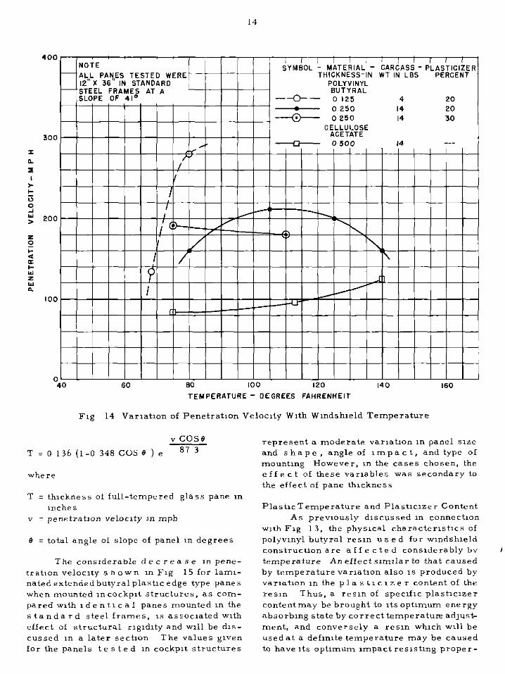
perienced in bird impact is indicated in Fig. 14, where the maximumstrengthof a 0.2%in.
butyral plastic with 20 per cent plasticizer
content tested with a 14-lb. bird carcass
occurs at 110°F. When t e s t temperatures
below 80” F were used, the penetration ve-
locity dropped rapidly because of the decreased
elongation of the plastic at such temperatures.
A complete study at these low temperatures
has not yet been made.
Effect of Pane Thickness
Fig. 15 shows the e f f e c t of thickness
upon impact strength of full-tempered glass
plates, cellulose acetate sheets, and butyral
plastic interlayers in the laminated extended
plasticedge type panes. The thickness of the
glass faces is notincluded in data concerning
the latter type of pane because of the relatively
small contribution of the glass to the impact
strength of this combination.
In Fig. 15 are included data obtained
with panes of the laminated extended plastic
edge type tested both in aluminum alloy

Acetate With Temperature
cockplt structures and II, the smpllfled steel frame s used f o r comparat,ve tests It 15 shown that the panel penetratmn velocity, w h e r e failure occurs ,n the butyral plastx mterlayer,vanes approxmmtelyas the loga- rlthm oi the plastic thickness This can be expressed by the equatmn
Y
T = Kec
where
T = thickness of vmyl plastx III Inches v = penetratmn velocity of wmdshleld
panel xn mph K & c = constants
For the three curves >n Fig 15 II,- volvmg lammated panels, the followmg con- stants may be subst,tuted in the above ex- pressmn which ~111 mdlcate the approxmnate
slope and pas~tmn of each curve
structure Wmd- Weqht Supportmg shxld of Value Value Wmdshleld Slope Carcass of of TestPanel (degrees) (lbs ) K c
Standard 5tee1 41 4 0 0372 230 5 Frame
Cockplt 40-46 4 0 0498 180 0
Standard Steel 41 14 0 0121 54 6 Frame
In the case of the full-tempered glass panels, a m”re complete expression was de- rived This expresslo,, also mcludes the effect of varymg the wmdshlcld slope from 41 ’ to 60” and may be stated as follows
14
400 NOTE
[ / 1 i , ( I , 1 1
-ALL PANES TESTED WERE SYMBOL - MATERIAL - CARCASS - PL$~m;I;f,
THICKNESS-IN WT IN LSS 12°K 36” IN STANDARD
-‘STEEL FRAMES AT A PoLoLy~NY~
SLOPE OF 41’ -u- 0 12s 4 20 1 ,
TEYPERATURE - DEGREES FAHRENHEIT
Fig 14 Varlatmn of Penetration Velocity With Wmdshleld Temperature
vcose T=O136(1-0348COSe)e 87 3
where
T = thickness of full-tempered glass pane m mche s
v = penetratmn veloczty m mph
B = total angle of slope of panel III degrees
The considerable de c r e a s e in pene- tratlon velocity s ho wn in Fq 15 for laml- nated extendedbutyral plastic edge type panes when mounted ,n cockpIt structures, as corn- pared with Ed e ntl c a 1 panes mounted III the standard steel frames, IS assocmted with effect of structural rlgldlty and ~111 be dls- cussed m a later sectmn The values given for the panels t e s t e d m cockplt structures
represent a moderate varmtmn m panel sme and shape, angle of Impact, and type of mountmg However, m the cases chosen, the effect of these varmbles was secondary to the effect of pane thickness
PlastIcTemperature and Plastlclzer Content As previously dlscussed m cannectmn
with Fig L 3, the physlcal characterlstxs of polyvmyl butyral res.m u E e d for wmdshleld construction are a f f e c t e d conslderably bv temperature Aneffect smnlar to that caused by temperature varmtmn also 1s produced by varmtmn ~n the p 1 a s t I c I z e r content of the resin Thus, a resm of specific plastlclzer contentmay be brought to Itsoptnnum energy absorbmg state bycorrecttemperature ad]usL ment, and conversely a resm whxh ~111 be usedat a defmlte temperature may be caused to have Its optimum Impact reslstmg proper-

LEGEND
MATER1P.L SLOPE CARCASS TEST STRUCTURE DEGREES WT IN LGS
PO-- POLYVINYL GUTYRAL 4, 4 ST0 STL FRAME (20% PLASTICIZER1
-.- 40.46 4 tOCKPlT
-A- II 4, 14 ST0 STL FRAME
-----II--- FULLG;ty;ERED 41 4 II II II
II .I ,,
0- 125 15 2 25 3 4 5 6 7 6 9 IO 15
THICKNESS OF MATERIAL TESTED - INCHES
Fxg 15 Varmtlon of Penetration Velocxty With Wmdshxld Thuzkness
I ties at this temperature by adlustment of plastlclzer content
This relatmnshlp 1s shown bv the data glven,nFlg 14 It 1s seen that with 0 25-m thlckbutyralplastlc of 20per centplastIcIzer content testedwIth a 14-lb bird carcass, the maxm~um mxpact b t r e n g t h 1s obtamed at about 110” F With 30 per cent plastlclzer, the optimum temperature has not be en de- termmed accurately but test results mdlcate It to be not more than 80” F With 12 per
cent plastlcmer, the optxnum temperature appears to Increase conslderably, although msufflclent data have been obtained for a complete determmatlon
It IS evident that with a given plastlclzer content, the panel unpact strength 15 high m value wvlth~n a partxular range of temper- atures At low e r and higher temperatures beyond this range, the xmp a c t strength de- creases at a very rapld rate At 68’ F the m,pact strength of polyvmvl butyral with 20

16
per cpnt pla%tlclaer content, as measured in terms of penctrat1on vrloc~ty of 0 125-m plastic with a 4-lb carca~=., IS only about “w-half the value at 80” F
It 15 lndlcated by the data given m Figs 13 and 14 that advantage might accrue from use of hlghlyplastlclzed reslnfor low temper- aturF condltlons Howe-e=, consldrratlon must be given to the very low strength and high elongation of such materml under any high temperature condltmn which may be en- countered Forpractlcal we, butyral plastic with a 20 per cent plasticlrer content has be e n consIdered an optmourn value for air- craftwlndshleldappllcatlon, especmlly where high temperatures assocmted with hot-al= de-lcmg methods exxst However, under s p e c 1 a 1 temperature condltmns, a different plastlcxzer contentmlghtbe advantageous and also practical
The data given I” Fig 14 also show that aIrcraft type cellulose acetate, us a b 1 e for winds hleld materml on light aIrcraft, In- creases rapldly in resistance tc nnpact as the temperature 15 mcreased above 120-F It 1s mdlcated that cellulose acetate of higher plastxmer content would exhlblt high nnpact strength at lower temperatures
Impact Strength of Front De-lcmg Pane m Double-Pane Arrangement
The thickness and cornposItIon of the front de-lclng pane of a double-pane wmd- shield arrangement normallv &re lumted by requirement for good thermal transmlsslon characterlstlcs In particular, this requre- mentplaces severe lnnltatmn upon the use of a plastic such as butyral m this pane, as the thermal transrms slon of butyral 1s only about one-fifth that of glass Accordmgly, It may be expected that the front pane can contrIbute only a small portlon of the Impact strength of thr combmatlon
‘I hree types of front pane construction were Included in the tests, as shown m Fig 16 Spec~flc data were notobtamed to de- termme the p r e c 1 se effect of each type of front pane constructmn, but It was evldpnt from the test results that the front pane had small effect upon the Impact strengrh For example, a 0 25-m full-tempered glass front pane adds little If any strength to a lammated glass-plastic type rear pane, and a lammated front pane with 0 060-m butyral plastic Interlayer adds about 10 per cent to the
NOTE
Fig 16 Edge Detail of Various Front Pan-s Tested in Double Pane Type Wmdshlelds
strength of a rear pane contammg 0 25-m butyral plastic thickness
The tests upon which these conclusions 1
are basedwere carried out with bird carcass weights of 4 to 16 pounds It 15 lndlcated from fhghtaccldent experience, and from theoret- lcalconsideratlons,that a front pane of 0 25- i m full-tempered glass provides ahxgh degree of protectIon agamst small birds of less than 1 -lb weight In such experience, at common aircraft velocztles, the bl rd carcass 1s re- pelledwlthno crackmg or damage to the wind- shield panel

17
Effect of Mountmg btructure Upon Panel Impact btrength
A detaIled d, s c us s 1 o n of wmdshwld supportmg structures and arrangements ,s g,ven ,n a later sectIon of th,s report How- ever, ,t has been observed that the ,mpact strength, or penetrat,on veloc,ty, of a g,ven type ofwmdshxldpanel w,ll vary over a con- s,derable range of values, dependmg upon the partxular structure used No deta,led analy- SIS or spec,f,c measurements were made ,n th,s partmular connect,on.butvarlous general observations may be dIscussed
It 15 shown ,I, Figs 11 and 15 that an approxmate 125 mphdecrease ,n penetration veloc,ty exists for wmdsh,eld panels of Ident,- cal plastic th,ckness when mounted in cock- p,t structures I at h e r than ,n the standard steelframeused for comparat,ve tests Th,s decrease ,n penetration velac,ty may be at- tr,buted to
(1) an ,ncrease ,n the elastic r,g,d,ty, and a decrease ,n ease of structural bucklmg, ,n the cockplt structure (2) var,at,on ,n the elast,c and bucklmg character,st,cs of the co c kp 1 t structure aroundd,fferentportlons of the wmdshleld, resultmg ,nlocal,~edstressesin the panel (3) var,at,on 11, the un,form,ty of bolt attachment of the panel to the cockplt structure, resultmg ,n locahzed stresses ,n the panel
All of these factors are of ,mportance ,n determmng Impact strength of the panel The character,st,cs of the standard steel frame used ,n the tests were, ,n all of the above respects, suchas to tend toward m&x,- Illurn pane1 strength
As several of the co c kp, t structures tested p rovlde d fa,rly urnform structural supportandattachment of the wmdshwld panel, ,t may be concluded that the elast,c andbucklmg character,st,cs of the support,ng
1 4tructure contnbute a fa,rly large portmn of the total panel strength difference noted
Insuffwlent c o c k p, t structures were tested, w, th approxmately equ,valent panel mountmgangle andwdely different structural ngld,ty, to pernut measurement of the elfect of such structural d,fferences The cockp,t data ,ncluded m F,gs 11 and 15 were for cockp,ts of large aircraft w 1 th a relat,vely r,g,d structure desqned to w,thstand mternal pressure loads
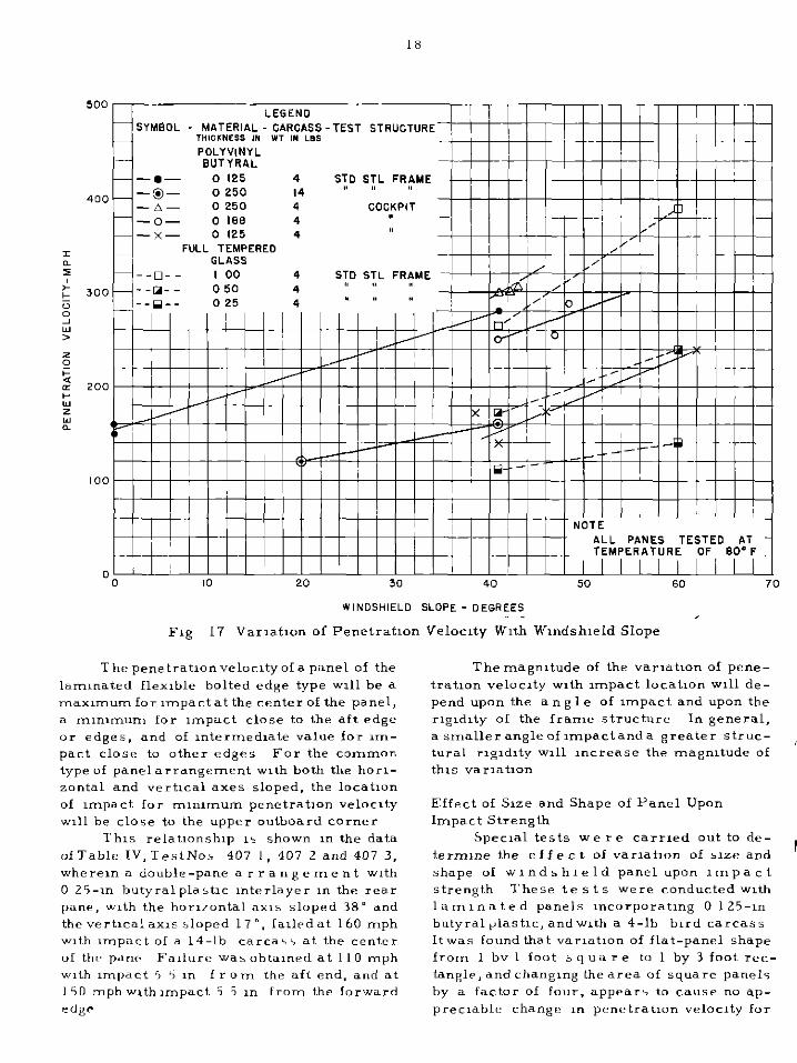
Effectof Angleof ImpactUpon Panel Strength In F ,g 17 are shown data obtamed w,t,
panes of ,dentxal plast,c th,ckness tested ,n the standard steel frame at var,ous angles of ,mpact,andotherpanes of the same th,ckness tested ,n var,ous cockplt structures ,n wh,ch the angle of mountmg varied T es t results obtamed w,th full-tempered g la s s panes of d,fferent th,ckness are also shown
Although known advantages exist from the standpomt of ,mpa c t resistance ,n de- creasmg the angle of mpact by sutable de- s,gn and layout of the wmdshwld in the a,=- plane, conslderatlon must be g,ven to the re- sultmg ,ncrease ,n optxal d,stort,on and de- crease ,n general v,s,b,l,ty
Anexceptlon to the general rule for var,at,on of penetrat,on velocity w,th ,mpact angleof lamlnatedextendedplastlc edge panes, as shown ,n F,g 17, 1s found ,n the case of very small panes and where unpact occurs at the aft edge of a sloped large pane In such cases, at some m,n,m,rn velocity the b,rd carcass tends to crack the glass faces and to p o c k e t mto the plastic mterlayer as the latter stretches Because of the proxmnty of a frame member tc the rear, the carcass cannot sl,de off the sloped panel Under such c,rcumstances, the penetratmn veloc,ty 1s to a large degree mdependent of the w,ndsh,eld angle
Effect of Locat,on of Impact on Panel The penetratlonveloczty of a wmdshwld
of the lam,natedflex,ble bolted edge type w,ll vary over a considerable range of values de- pendmg upon the locatmn of tne ,mpact upon the panel Some data ,n th,s connect,on are g,ven ,n Table IV However, observatmns of a large number of tests ,nd,catr that the quantltatwe effect produced by varlatmn of lmpactlocatlondeprnds upon severe,1 factors, and the effect can be described only w,th re- gard TO general tendencxs
The cause of such vanatmn 1s partmllv explamed ,n the prev,ous sectxon, ah e r e ,t was shown that mpact ,ut forward of an aft edge of the wlndsh,eld panel w,ll result ,n a local pocketmg of the b,rd carcahs w,th the adjacent r,g,d structuralmember. preventmg sl,d,ng act,on In add,t,on to this factor, ,m- pactnearanyof the edges of the panel results in large and localized shearmg and tenslo,, stresse? ,n the plast,c mterlayer along the edge of the panel ,n the ,mmed,ate v,c,n,ty of the ,mpact
*LL PANES TESTED PIT TEMPER*T”RE OF SOOF
0 ’ I II I ’ II I ’ I IllI I II II II III I I i I II 0 10 20 30 40 50 60 70 WlNDSHlELO SLOPE - OESREES
~1~ 17 Vanatlon of Penetratmn Velocity With Wmdshleld Slope
Thepenetratlonvelocltyofapanel of the larmnated flexible bolted edge type ~111 be a maxrnumfor mpactat the center of the panel. a m,rnmum for nnpact close to the aft edge or edges, and of Intermedmte value for zm- pact close to other edges For the common type of panelarrangement with both the horl- zontal and vertical axes sloped, the locatlon of mlpact for ml*lmUm penetration ve1oc1ty will be close to the upper outboard corner
This relatmnshlp 15 shown I* the data of Table IV, TestNos 407 1, 407 2 and 407 3, where,* a double -pane a r r an g e me n t with 0 25-l* butyralplastlc lnterlayer I* the rear pane, unth the hor,/o*tal axis sloped 38” and the vertIcalaxIs ilopcd 17”. lallpdat 160 mph with impact of a 14-lb ~arcaii at the center of thr p*ne Fa,lure was obtaIned at 110 mph with rnpact 5 5 I* from the aft end. and at 150 mphwthmpact 5 5 I* from the forward etlgr
The magnitude of the varmtmn of pene- tratlon velocxty w,th nnpact locatIon ~111 de- pend upon the an g 1 e of rnpact and upon the r,gldlty of the frame structure I* general, a smaller angleofmpactanda greater strut- , tural ngldlty ~111 increase the magnitude of this varlatlon
Effect of Sme and Shape of Panel Upon Impact Strength
Specml tests we r e carried out to de- ternune the e f f e c t of varlatlon of ,lze and r
shape of wIndshIeld panel upon xmpact strength These tests were conducted w,th laminated panels lncorporatlng 0 125-l* butyral$astlc, andwIth a 4-lb bird carcass Itwas ‘ound that varmtlon of flat-panel shape from 1 bv 1 foot 5 qua I e to 1 by 3 foot rec- tangle, and changmg the area of square panels by a factor of four. appear> to cause no ap- precmble change I* penetratmn velocity for

19
impact no r ma 1 to and at the center of t.he
panel. However, a 2 by 2 foot panel exhibited
40 per cent greater impact strength than the
lesser sized panels when tested at an angle
of slope of 41’ (see Table II, Type 201). Ad-
ditional te s t s are necessary to verify pre-
liminary results and determine further the
c o m b in e d effect of angle and variation of
panel shape.
A corroboration of the tests of the flat
2 by 2 foot panel as described in the preceding
paragraph is indicated in tests performed on
relatively large, highly sloped, curved, lami-
nated panes which were attached to the cock-
pit structure by means of the clamped edge
type of mounting. Data concerning this type
OfpanelaregiveninTable IforTypeNo. 111.1
The unusually high strength of this panel with
only clamped edge mounting may be partially
explained by the large angle of slope of 63”,
but the high strength also undoubtedly is asso-
ciated with the large panel size. Failure of
the pane 1 was of a local nature and, except
where impact occurred close to one edge of
the pane, the tensile forces developed in the
plastic interlayer were so small for each
unit length of the large edge dimensions that
the panel didnot pull from the frame as ordi-
narily occurred with smaller panels of this
type. A high-speed mo tio n picture study of
the result of impact occurring near the for-
ward edge of windshield Type 111 .l is shown
in Fig. 18. This illustrates the failure of the
clamped edge type of mounting. In this case
the carcass is deflected upward because of
the unusually great slope of the windshield.
The formation of a cloud of glass splinters is
also evident as a r e a c t i o n to t h e impact.
Comparable splintering of the inner face into
the cockpit also occurs.
Edge Mounting of Laminated Flexible
Bolted Edge Type Panes
I n general, the test results have shown
that the edge attachment of a laminated flex-
ible b o 1 te d edge type pane forms the most
criticalpartof the installation with regard to
impact strength. The method of transmitting
tensile and shear stresc:es from the plastic
interlayer of the panel into the metal structure Fig. 18 Single Frames From a High Speed
is of primary importance. Motion Picture Film of Impact
The type of failure occurring at exces- Test on Curtiss-Wright C46A
sive carcass velocities in a windshield panel Cockpit. Time Sequences Measured
with a de qua t e edge mounting i s shown in From First Frame are 0. 004,
Fig. 19, with the plastic interlayer absorbing 0. 013, and 0. 052 Seconds

Fig. 19 Example of Failure at Center of Laminated Pane With Polyvinyl Butyral
Inte rlaye r
maximum energy before tearing. This type
of failure indicates optimum butyral plastic
temperature and sufficient s t r e n g th in the
edge mounting of the panel and the frame at-
taching the panel to the cockpit structure.
In Fig. 20 is shown a typical edge
mounting arrangement for panels of such type.
The impo r tant variables in the method of
edge attachmentare (a) thickness, width, and
type of metal insert strip, and (b) diameter,
type , spacing, and edge distance of mounting
bolts.
The thickness of the metal insert strip is
critical. If the s t r i p is too thin, the
mounting b o 1 t s passing through the strip
will tear through the edge to cause failure.
Too great a thickness of the metal insert,
with corresponding stiffness and decreased
butyral plastic thickness in the edge section,
results in shearing of the plastic interlayer
along the inside edge of the insert, as is
shown in Fig. 21. The optimum thickness
of the metal insert is related directly to
the thickness of the plastic interlayer.
(a) Metal Insert
Aluminum alloy 24S-T is commonly used
as the material for the metal insert strip,
although steel alloys also may be used.
InTable Vare classified, according to type
of failure, wind s hi e 1 d panels that were
tested both in cockpits and the standard
steel frame. Thefirstcategoryof failures,
where the extended plastic edge sheared at

21
.
Fig. 20 Design Requirements for Edge
Mounting of Laminated Panes
With Polyvinyl Butyral Interlayer
the mounting bolts, indicates either lack of
insert or insufficient thickness of insert
when the mounting bolt size, spacing, and
edge distance are satisfactory. An example
of f a i 1 u r e due to lack of adequate insert
thickness is shown in Fig. 22.
In the second category of failures in Table
V are shown some test results where the
butyral plastic laminated pane sheared at
the line of metal insert, indicating in
several cases excessive thickness in the
metal insert.
This t yp e of failure is shown in Fig. 21.
Rigidity of the supporting structure, and
lack of adequate width of the insert so that
it does not extend a sufficient distance be-
tween the glass faces, also contribute to this
type of failure. The effect of rigidity of the
s up p o r tin g structure will be discussed
later.
It may be concluded that the thickness of
24S-T aluminum alloy metal insert strip
should be betweenone-sixthand one-quarter
Fig. 21 Example of Failure Resulting From Impact Test Where Plastic Interlayer Sheared
Along Inner Edge of Metal Insert

Fig. 22 Example of Failure Resulting From Impact Test Where Plastic Edge and
Metal Insert Sheared at the Mounting Bolts
the thickness of the butyral plastic inter-
layer, where the plastic interlayer thick-
ness is 0.188-in.or less. Itappears desir- able to use a minimum thickness of metal
insert for the thinner plastic interlayers.
With regard to width of the metal insert
strip, it has be en found that satisfactory results are obtained if the metal insert
strip extends at least 0.25-in. between the
two g la s s faces of the pane. If the strip
does not extend between both glass faces
in this manner, a strong tendency exists
for failure of the plastic interlayer in shear
along the inside edge of the strip.
(b) Mounting Bolt Size and Spacing
The loads developed by bird impact on a
windshield pane of the laminated bolted
edge type are transmitted to the aircraft
structure through the bolts w hi c h attach
the pane to the frame. The type, size, and
s pa c in g of such bolts, therefore, are of
considerable i m p o r t a n c e in determining
the impact strength of the installation.
There are shown in Table V data covering
test results obtained with various mounting
boltarrangements. The data were secured
with various panel thicknesses andmounting
structures.
Bolt arrangements shown in Table VI for
different butyral plastic interlayer thick-
ness, o r equivalent arrangements, ha v e been indicated by test to be satisfactory.
The values given in Table VI are average
figures and will be conservative for panels
with very high angle of slope or with very
+

23
reslllentmauntmg structure, and probably represent msufilclent s t r e n g th for ex- tremely small pane 1 slope clr extremely rlgldstructure It 1s generally establmhed that the bolt size and d 1 s tan c e between bolts should prowde strength equvalent to a 2-m spac,ng of No 10 steel bolts (100,000 psi H T ) for 0 125-l” plastic lnterlayer thickness. and a 1 -I” spacmg of ldentzcal bolts for a 0 25-l” Interlayer
.thlckness
I In order to obtal” the necessary strength ~“the bolt attachment, It appears desirable
I to use s m a 11 bolts with c lo s e spacing, rather than large bolts with wide spacing
,” but of equvalent total strength, 1” order to secure the most urnform load dlstrlbutm” I” the plastic lnterlayer and metal Insert
The forces o” the mou”tlng bolts are a comblnatm” of shear and tens,“” forces, but the relative magnitudes of the two force components depend upon the ease of ro- tatmn of the frame structure, the stiffness of the plass, and other factors
Adequate distance between the center-line of the bolts and the edge of the panel 1s of nnpartance in p r e v e n t 1 n g the mounting bolts from sheanng through the plastx edge of the panel The mlnlmum suitable edge distance 1s a functmn of metal Insert thickness andother factors, but It appears that a distance between the bolt center- lme and the edge of the pane of not less than twice the bolt d,ameter ~~11 prowde x&factory strength
Wmdshleld Frame, 5111, and Past Des,gn The deslg” of a sutable mounting and
supporting structure for an mlpact resmtant wIndshIeld lnstallatm” presents a complex problem T h 1s 15 true partxularly w 1 t h a double-pane de-xmg typr w,“dshleld where It 1s usually requred that the rear pane, I” whlchmostof the mpactstrength 1s ~“corpo- rated. should be mounted 50 ah to be readxlv opened I” illght far clra”,ng purposes
A$ each wlndshwld ,“stallatm” deslg” var1c\ wrdely I” detal, and as no complete andprecxe qua”tltatlvedPtrrml”atlD”has yet betn made of thr forcei exlstmg dur,“g bird colll<m”, the p r e s c n t report lncludrs onlv gem’ral conclus~oni I” thl 5 co”“rct,o”, and
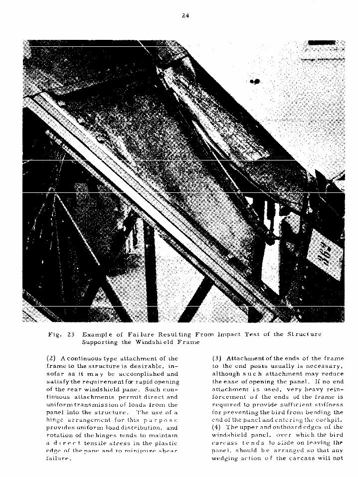
data r e 1 a tl n g to speclfx practxal des,g”s which may be generally applxable to other designs A” example of failure of supporting structure resulting from Impact on the wind- shield panel 1s show” I” Fig 23
The f o 11 D w 1 n g conclusmns have been draw” from generalabservatm” and analysis of the test results
(a) T e s t s made upon various cockpIt mstallatmns lndxate that a relatively elastic structure which buckles readily possesses better zmpact characterlstlcs than a heavy rlgld structure No heavy reinforcement of a cockplt s t r UC tu r e, such as added sheet stiffeners u, the canopy, appears necessary for bird colllsm” resistance except I” verv light structures Principal pmnts of failure I” the structure are usually I” the wlndshwld frame, I” the attachment of the frame to the ~111s and posts, and the attachment of 5111s and posts to the prmxary structure
A umform structural rlgldlty around the wmdshleld a p p e a r s desirable to elmunate sectmns of high shear stress concentratmn I” the butyral plastw mterlayer of the panel
(b) No a ppa r en t advantage exxste 1” utllmng heavy r,gld post, at the ends of the wlndshleld panel, or between panels, except to reduce glass cracking 1” panels ad,ace”t to the point of impact However, such posts may fall If the,= attachment to the structure possesses lnsufilclent strength
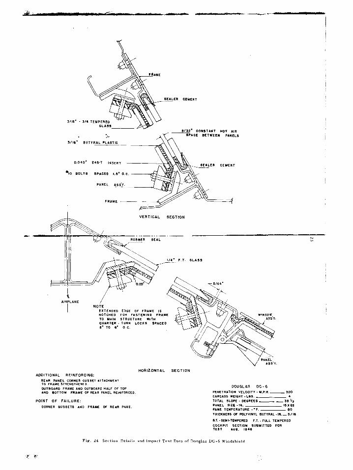
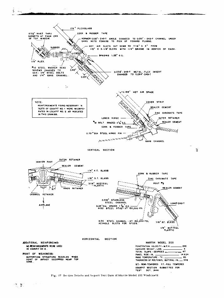
(c) The rear pane of a double-pane wmdshleldlnstallatm” 1s required to possess high m,pact strength, and al!,” 15 ordlnarllr required to be r e a d 11 y removable I” fl,ght borne examples of the attachment to the struc- ture of double-pane lnstallatlans tested ark show” I” Figs 24 to 29, and the point of apparent untlal iallure of the attachment 1s lndzcated
The conclusions draw” from tests of a large “umber of such l”stallat,o”s are as follows
(1) The wlndshleld frame. attached to the edge of the pane, should be as con- tlnuous as p o s s 1 b 1 e , particularly at corners. and should possess sufflclent stiffness to transmit the ,mposed loads from the panel mon”t>“g b o 1 t s to the points of attachmeEt of the frame to the structurewlthout l er,ous drformatlon
24
Fig. 23 Example of Failure Resulting From Impact Test of the Structure
Supporting the Windshield Frame
(2) A continuous type attachment of the
frame to the structure is desirable, in-
sofar as it may be accomplished and
satisfy the requirement for rapid opening
of the rear windshield pane. Such con-
tinuous attachments permit direct and
uniform transmission of loads from the
panel into the structure. The use of a hinge arrangement for this p u r p o s e
provides uniform load distribution, and
rotation of the hinges tends to maintain
a d i r e c t tensile stress in the plastic
edge of the pane and to minimize shear
failure.
(3) Attachment of the ends of the frame
to the end posts usually is necessary,
although s u c h attachment may reduce
the ease of opening the panel. If no end
attachment is used, very heavy rein-
forcement of the ends of the frame is
required to provide sufficient stiffness
for preventing the bird from bending the
end of the panel and entering the cockpit. (4) The upper and outboard edges of the
windshield panel, over which the bird
carcass tend s to slide on leaving the
panel, should be arranged so that any
wedging action of the carcass will not
,
s’ CONSTANT HOT AIR SPACE SETYEEN PANELS
90 BOLTS 5PLCEO 1.6’ O.C.
VERTICAL SECTION
---_- _..- _
SEAL :
114’ F.T. I
f AIRPLANE
I
NOTE EXTENDED EDGE OF FRAYE IS
~~ ~-~YtY” CD.YC
OUANTEN - TURN LOCKS SPACED
AOOITIONAL REINFORCING:
REAR PINEL CORNER SUBSET LTTACHYENT TO FRAME STRENOTHEIIED.
HORIZONTAL SECTION
WTSOANO FRAYE AN0 OWSOARO HALF OF TOP AN0 SOTTOY FRAME OF REAR PANEL REINFORCED.
POINT OF FAILURE:
CORNER 5”SSETS All0 FRAYE OF REAR PANE.
DOUGLAS DC-6
PENETRATIO” “ELOCIT” - Y.P.“. - 300
CARCASS WElOHT -LSS. 4
TOTAL SLOPE - DEGREES 3s ‘/*
PANEL SIZE -IN. lSXZ5 PA”E TENPENATUNE -*F. SO
THICKHE OT POLYVINYL BUTIRAL -I”. - 3116
8.1. -5EYCTEYPE”EO F.T. -FULL TEMPERED
COCKPIT SECTtO” S”BYlTTE0 FOR TEST NO. ,945
Fig. 24 Section Details and Impact Test Data of Douglas DC-6 Windshield

CH‘NGEO EXTRVOEO TYPE HINSE
ER iMOLDED
NAS s-32 SCREWS SPACED S/4’ O.C.
CONTINUOUS ST0 ANOUNO ENTIRE FRAME TlNUOU5 PIECE
INUOUS NETAINEN
CONTINUOUS PIECE AN
ORIQINAL HINQE DESIQN
0.047’WALLTHICKNESS
STEEL NINSE PIN DIP. 0.0s’
IMPROVED HINQE (EXTRUDED)
0.08’ WALL T”lCKNESS -
STEEL HINQE PIN HOLE DIA DIA. O.l5l’ 0.125’
VERTICAL SECTION
PO,QT NONE
POINT OF FAILURE:
ONlQlNl‘ HINQE FAILED.
- WS-T INSERT
DIRECTION OF F OF NOT AIR
SPACE
OUTBOARD POST
YANIFOLD --(J UNITED AIRLINES DC-4
PENETRATION VELOCITY-M.P.H.- 550 CANCbSS WElDHT- LB. 4
HORIZONTAL SECTION TOT&L SLOPE - OEQNEES 41 PANEL 5!ZE- IN. I4 x 32 PANE TEYPERATURE- =F. so THICKNESS OF POLIYlNYL SUTISLL-IN. -,,I.
8.7; SEW-TEYPEREO F.T.- NLLTEYRRED
COCNPIT SECTION 5UBYITTED FOR TEST NOV. lB4B
Fig. 25 Section Details and Impact Test Data of United Airlines DC-4 Windshield

UTIRAL PLASTIC
\ 0.2S F.,. SL‘S’s
1 AIR LANE
S/32’ RIVETS SPACE 1’ O.C.
,
HO, AIR OP
LOCK ASSEYSLI lNNER WINDSKIELD WIT” LOCK IN CLOSED POSITION
VERTICAL SECTION
ADDITIONAL REINFORCING: NONE
HORIZONTAL SECTION
POINT OF WEAKNESS:
PRlNClPAL WEAKNESS OCCWRED A, EXTEHOEO EOSE OF MNE WHERE TM PLASTIC SHE.REOA, WE RIVETS. THIS
FAILURE WAS DUE TO THE LACK OF A YETAL INSERT IN TRE LOSE OF T”E PANE.
CURTISS-WRIGHT C46E
PE,,E,RA,lC# VELOCITY- M.PH. 210 c‘NC‘SS WEIGHT- LSS. 4 TOTAL SLOPE- DEGREES 43 PANEL SIZE-IN. 13*24 P4N.E TEYPER‘TUNE- V. GO THICKNESS OF POLYVINYL SUTIRIL-IK- l/S
ST.- SEW-TEWEREO F., - F”LL,EYPSREO
COCKPIT SECTION SUSYlTTEO FOR TEST SEPT. IS41
Fig, 26 Section Details and impact Test Data of Curtiss-Wright C46E Wmdshield
& 114. PLEXISL‘SS
$~:;N,:j;~ END\v a RUsBE” ‘IPE 7 FORMER 0.051’- 24S-T ‘“SLE CHANGED TO 0.051’ - 243-T CHANNEL UNDER
GINO WUTS FOW‘RD TO PICK UP FOWARD FLAKBE.
HOT AIR SLOTS CUT DOWN TO 7115’ X 3. FRON
l/E’ X 3-I/5’ SLOTS WITH 114’ SRIDQE IN OENTER OF
- SP‘CIIIQ 1.25’ 0.0.
NOTE:
REINFDRCEYENTS FOVND NECESSARY IN
TESTS OF COCXPIT ND. I WERE INCORPO- RATED IN COCKPIT NO. $! AS IWDIC‘TED IN THIS OR‘WINQ.
OUTER RETAINER CEKTER POST
/ I CHANNEL RETAINER
1 AIR LANE
0.032”- 245-T METAL -FLEX INSERT TO
\ kf-O.lSS" HOT AIR BP‘CE
LER GEYENT \ W C CHROMATE TAPE
LOWER Hl”SE OUTER RETAINER
l K) BOLT SPACED I lb,
CORK B RVSSE
E‘CR.
‘DIA. STEEL “INSE PI
VERTICAL SECTION
CEYENT
F.1. 8L‘SI
S.T. OL‘SS
CONK B RUSBER TAPE
ZINC. t”ROY‘TE TAPE
RETAINER
*DDITlONAL REINFORCING:
NO RKINFORCEYEUTS !XERE USEC IN COCKPIT NO.8
POINT OF WEAKNESS:
0.015 51 STEEL
0.25’01‘. SPA< 4150 STEEL
4130 STEEL C”‘“NEL . “T 150,000 PSL XEYHOLE SLOTS FOR STUDS.
L/5’ BUTIR‘L PLASTIC
HORIZONTAL SECTION
MARTIN MODEL 202
PENETRATION VELOCITY _ Y.P.H. - 251 CARCASS WEIGHT - LSS. 4
TOTAL SLOPE - DEGREES 47
PANEL SIZE-IN. ,4X24
BUPPORTINB BTRUOTUBE 8UCKLEO WHEN POINT OF IYPACT OCCURRKD NE‘” TOP EDBE.
PINE TEYPERITURE - ‘F. BO
T”,CXNESS OF POLYVINYL BUTIR‘L- IN. _ S/l5
PT.- SEMI-TEMPERED F.T. - FULL TEYPEREO
COCKPIT SECTION SUlYlTTED FOR TE5T OCT. IS45
Fig. 27 Section Details and Impact Test Data of Martin Model 202 Windshield

IO-32 BOLTS
FULL. TEMPERED 6L455
6 - SUTYR‘L ‘0% PLASTICIZER)
‘B - SEYI - TEYPERED GLASS D.057- NOT -ROLLED STEEL SUSSET.
COKTINUDUS ACROSS TOP 5 4’ DOWN E‘GN SIDE --- SIMILAR REINFORCEYEN, IN DOTTOY SILL.
VERTICAL SECTION UPPER SILL
VERTICAL SECTION OF MAIN WINDSHIELD PANEL
CENTER WINDSHIELD
ADDITIONAL REINFORCING: 5
0.000 IN. X 2 111. 24s’, EXTERNAL
RIGHT CLEAR VISION GUSSETS ADDED TO TOP ‘NO BOTTOM
WINDSHIELD WINDOW OF ALL WINDSHIELD POSTS
I-5/5’0.t.
I
K~,~OLTS. I-5/s-0-c. POINTS OF FAILURE:
CORNER GUSSETS ON REAR PANE
HORIZONTAL FR‘YE YEUBER LACKED STIFFNESS
VIEW A-‘
SECTION 5-S
VERTICAL POSTS FAILED AT POINTS OF INTERSECTION WITH COCKPIT
STRUCTURE
4’ . ,
BEECH MODEL 34
PENETRATION VELOCITY-Y PH __ 22D C‘Rt‘55 WEIEHT-LBS 4 TOTAL SLOPE -DEQNEES 46 PANEL SIZE -111. I7 x IO PANE TEYPER‘TURE -% so THICKNESS OF POLYVINYL BUTYR‘L-IN. 3/w
HORIZONTAL SECTION OF MAIN WINDSHIELD COCKPIT SECTION SUBMITTED FOR
AND ADJACENT PANELS TEST APRIL 1947
Fig. 28 Section Details and Impact Test Data of Beech Model 34 Windshield

NOTE 1
YETAL INSERT DOES BETWEEN THE SLASS
’ BUTYRIL PLAsnc
NOT EXTEND PACES.
l”SERT
VERTICAL SECTION
\ 0.064’ 245-T PLITL
P.4¶-1
ADDITIONAL REINFORCING:
NONE
HORIZONTAL SECTION
POINT OF WEAKkESS: BOEING MODEL 377
LAW OF YETAL INSERT THICKNESS CAUSED ExrElDED PENETRATION VELOCITY - Y.P.H.- MI
EDOE TO SHEAR AT THE BOLTS. LACK OF WIDTH OF C*RC*SS WEIWI - LBS. 4
WETAL INSERT C&USED PLASTIC ,O SHW BETWEEN TOTAL SLOPE -DEGREES 45
EDBE OFGLASS FACE &,I0 FRIYE. PANEL SIZE-I”. eoxeo PANE TEYPCRATURL -‘F. 80
THICKNESS OF WLYVINYL BUTYRAL-IN.- 114
S.T. - SEW- TEMPERED COCKPIT SECTION SUBYIYTEO FOR TEST NOV. lS4S
Fig. 29 Section Details and Impact Test Data of Boeing Model 377 Windshield

31
cause f allur e of bolts or structural members ca==y,“g the prmc~pal ,mpact load In many tests, wedgmg of the bird ca=cass along such edges has causd rotatmn of outsIde retuner st=,g and other members, and has resulted ~“twstlng andfalure of =eta,“l”g bolts (5) A variety of fast-actmn clamps. locks, and hooked lip arrangements for frame attachmenthave been tested, and are showninF,gs 24 to 29 Many such arrangements have prove” satisfactory 1” p I a c t 1 c a 1 I”stallatlo”s It 1s re- qured that such locking arrangements do not open as a result of impact loadmg. shockof Impact, a reactmnaftershock
(d) Center V-posts, and other posts at the ends of or between wlndshleld panes, usually ~111 reszst direct Impact wIthout serious fallore If firm attachment of the post to the structure ~smade L,ght-weight rIveted attachment flttlngs, w,th = ,ve t s I” tenslo”, have been found unsatisfactory
(e) After the bird ca=cass 1s deflected by the wlndshleld panel, It tends to slide over the structure at the top or outboard edges 01 the panel. and caose 5 t = u c to = a 1 bucklmg Max,mum strength of panel attachment and frame I” this =eg,o” 1s requxred
(f) The use of a rIgId type wlndshleld panel with clamped edge mounting, such as a clampediull-tempered glass plate, results I” large iorceso” the structure associated with the relatively small defo=mat,o” of the panel These forces are dIrected p=,“clpally to the rear and normal to the panel, and a rIgId and umfarm structure 1s = e qul= e d to transmit such loads
Applxatm” of some of these prlnclples 1s show”~“thep=act,cal~“stallat~o”sof Figs 24 to 29 Also show” 1” these lllus- tratlons are the various frame, 5111, and post componentdlmensmns, baltand rlvetarrange- ment and sizes, and other de tall s of con- structlon, as well as the velocltles at which panels mounted I” these structures were tested, and the apparent poxnts of ~“ltial structural fallore
Although no complete and precxe data have yet beenobtamed concernmg the Impact forces and the loads transmitted Into the structure from the wmdshwld panel, the fore- golngmformatmn onstructural se&Ions, bolt sizes and spacings provides a general gude I” tins connectmn
Impact Res,stance of Clear-Vlsm” and Auvlllary Windows
Tests lnvolvlng Impact upon corner cockplt windows ad,ace”t to the wmdshleld. side wmdows, andauxlllary transparent panels
above or be low the main wmdshleld panel, have bee” ,“cludedi”the present testprogram
Although suchpanels are usually mounted at a large angle of slope to follow the curvature of the fuselage, and are not 1” a direct fore and aft 1,” e with the pllot. It has been found fromnumerous tests thatfallure of suchpanels offers se=,ous hazard to the pllot In partlc- “la=, It has bee” found that panels forward of the pllotandwth appreciable frontal area may fall so that a part or all of the panel and
frame, glass o= p1ast1c sp11nters. o= portmns of the bud, ~111 be throw” I” a dlrectlon ap- p=ox,mately”o=mal to the plane of the wmdow and I” the general dlrectmn of the pllot
Panels of this type which were tested Included laminated safety glass with clamped edge support, laminated flexible bolted edge ~“stallat~o”s,a”dmethylmethacrylate plastic panels Some of the lnstallatlons tested are described I” Tables I and II, which also show the correspondmg test results
The results of Impact tests upon such w,“dows e re generally slmllar to those ob- taned with Identical panel materials and panel mounting methods I” mar” wmdshwld panels Panels w,th clamped e d g e mou”t,“g usually have low ,mpact strength and, upon failure. tend to be pulled out of the mounting frame I” one or several large p,eces which may be throw” ac=oss the cockplt with conslderable force Methyl methacrylate panels also are r e 1 a t 1 v e 1 y weak, and fall by breakme Into largefragmentswlth sharp corners andedge Methyl methacrylate panels above the ma,” w,“dshleldhave beenpenetratedm some tests by the bIrdcarcass slldlng upwardafter direct Impact upon the mal” wndshwld panel
The lamxnated llexlble bolted edge type of panel ,“stallat,o” ha\ been show”, by the tests, to provide the maximum ,mpact strength Ior auxll,a=y w,“dows as well as for mal” wlndshleld panels In general, the bame re- latmnshlp\ betwte” penetratlo” velocity and panel thxknpss, rdgr mountmg. metal Insert arrangement, panel ttmperature, and other drtalls of panel constructlonand arrangemerlt applyas alreadydlscusscd in connectlo” ~11th
the mal” wmdshxld ,“stallatlo” HOWeK=. brcause of the usual small size of such WI”-

32
dows m relatlo” to normal wmdshleld sxe, several Impad characterlstlc; whIchappeared Inthe larger panels are of especlallmportance m connectxon with the smaller panels
Because of the usual small sxze of such panels, bird Impactupon the panel IS close to all edges and r e s ul t s m high forces m the panel mountmg and frame In addltmn, the small sxe of the pane results m a pocketmg effect of the bird m the panel as the plastic undergoes stretchmg, whmh tends to neutralize the effect of the large angle of slope usually used for such wmdows The effect of Impact uponsmallwmdows setat high angle of slope, therefore, 1s slmllar to the effects already dIscussed m connectlo” with panel sze and pane1 slope
It may be concluded that m the design of such windows only slight conslderatmn should be given to the effect of an Increase of slope over mo de rate angles of slope m determmmg butyral plastic mterlayer thxk- TESS, If the forward area of the panel 1s ap- preclable. Also, no decrease m sze or spacmg of mountmg bolts should be made beyond that requlredforamamwmdsh,eldpanelofmoder- ate slope and slmllar plastic thxkness
Tests of avarvetyof hIngedclear-vzslo” wmdows md,cate the need for strong attach- ment, posltlve actmg locks 01 high strength, and rIgIdframe to carry the panel edge forces to the pomts of attachment to the structure Fallore of wmdows has commonly occurred through o p en 1 n g of the lock durmg Impact, iallure of portlons of the lock, iallure of the hmge or Its attachment to the structure, or severe dIstortIon of the wmdow frame In- sufflclent systematic data have been obtaIned to permit s p e c 1 f 1 c conclusmns concernmg strengthrequrements for suchframes, locks, and hmges
Optical Devlatlon Measurements OptIcal devlatmn measurements we r e
made upon certam of the panes used for Im- pact tests Because of the relatively small number of optlcal tests carried out, and as no selectmnofpaneswasmade for such tests. the results are not completely representative of the optlcal characterlstlcs which might be obtamed m commercial productmn
(a) Measurement with Plate Glass
Tests were made of optlcal devlatmns
produced by full-tempered glass plates from 0 25 to 1 25-m thickness The tests I”- dxate muchbetter aptlcal qualltles than those foundmbutyralplastlc lammated panes The maxImom devlatlon mdlcated by any of the panes Included in the tests was two mmutes of arc The maxImum rate of change was approximately 0 25 mm&es of arc per mch No correlatmn was found to exist between thickness of full-tempered glass and amount of devlatmn of lme of sight.
(b) Measurements with Lammeted Panes
OptIcal devlatmn measurements we r e made upon varmus lammated panes with drf- ferent thlckne s s combmatrons of surface glass and butyral plastx mterlayer Some results m this connectmn are show” m Fig 30 T he s e show that the proportmn to the total panel area of the area with less than three mmutes of arc devlatmn ~111 Increase as the rat,” of glass thxkness to plashc mter- layer thickness mcreases
Wltb the total glass thickness twice as greatasthe plastic thxk”ess,orwlththe thickness of each glass face equal to that of the plastic lnterlayer, approximately 50 per cent of the total panel area has optlcal devl- atmn values less than three mmutes If the total glass thickness 1s equal to the thickness of the butyral plastic, only about 25 per cent of the total panel area shows optxal devlatmn less than three *mutes
InFlg. 31 1s shown a typ,cal optxal devlatlon photograph of a glass plastx lam,- nated type wIndshIeld pane conszstmg of 0.25-m butyralplastx mterlayer and 0 188-m full-tempered glass faces The center area of the pane 1s relatively free from devlatlon of lme of sight. how e ve r , at the edges the amount of opt 1 c a 1 devlatm” mcreases m a characterlstx manner Usually th 1 s rela- tlvely high optical devlatmn assocmted with the edges of the pane 1s llmlted to a border area 01 one to two inches around the pane
SPECIAL PROBLEMS ASSOCIATED WITH IMPACT RESISTANT WINDSHIELD DESIGN
In addltmn to the speclflc data give” m prevmus sectlons of this report, certzun ob- servatlons were made whxh relate to design problems associated with Impact-resIstant wmdshzelds The se observations are con-

Fig 30 Varlatmn of Denatmn of Perpendxular Lme of Sight W,th Glass-Plast,c Thickness Ratm of Lammated Panes
cerned with thermal and splmtermg charac- terlstlcs of wmdshleld panels
Thermal Characterlstxs Several mdependent but closely related
problems concerned with thermal character- lstlcs of wmdshwld panels are encountered In p r a c t 1 c a 1 arcraft app11catlons These problems mvolve the heat t r an 5 m 1 s s 1 o n characterlstxs, and the varlatmn of pane 1 Impact strength with temperature as pren- ously dxscussed
The heat transmlssmn charactenstlcs, concernedwlth the provlsmn of adequate heat on the outer face of the windshIeld panel for de-lcmg p u r p o s e s and the nunnnlzatmn of heatradlatedfromthe inner face of the wmd- shield because of possible p&at dlscamfort, are related to the wmdshleld nnpact charac- terlstlcs prmclpally through the effect of the locatmn and thickness of the polyvinyl butyral or other plastx
Itls necessarytomrm-,nze use of butyral plastic between the source of heat r, the wmdshleld and the f rant face of the panel,
because of the relatively low heat transmlsslon of plastx as compared to glass For the same reason, the use of thick plastx layers behmd the source of heat 1s advantageous
The mamtenance of a reasonably urn- form temperature of the desired magmtude in the butyral p 1 a s t 1 c Interlayer of a wind- shield pane 1 in a practical alrcraft mstal- latmn IS a dlffxult p I‘ o b 1 e m However, as mdlcatedm prevmus dlscussmn, such temper- ature control IS requred to u,sure maxunum unpact strength In the approx,mate temper- ature range from 80’ to 140’ F, the butyral plastic wvlth 20 per cent plastxlzer exhlblts good energy absorbmg characterxtxs, but outslde of this range the a b I 11 ty to absorb energv of bird Impact decreases rapldly
Heatfor mamtenance of adequate plastic temperature x-, the wmdshxldpanel 1s readily ava,lable in wurlndshwld mstallatmns w h e r e heat de-lcmg 1s used Warm a,r circulated through a double pane arrangement. as commonly used for de-lang, provides suf- flclent heat for mamtammg the plastic tem- peraturesnecessaryforhlghstreng~ PartA
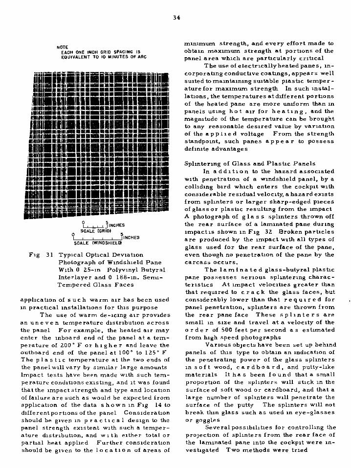
34
Fig 31 Typxal Optical Devmtmn Photograph of Wmdslueld Pane Wlrh 0 25-m Polyvmyl Butyral Interlayer and 0 188-m. Serrn- Tempered Glass Faces
applwatmn of 5 u c h warm air has been used ln practxal mstallatmns for tins purpose
The use of warm de-uzng alr provides an u n e v e n temperature dlstrlbutmn across the panel For example, the heated air may enter the inboard end of the panel at a tem- perature of 200-F or higher and leave the outboard end of the panel at 100” to 125’ F The p la s t 1 c temperature al the two ends of the panel wllvary by smular large amonnts Impact tests have been made with such tem- perature condltmns exlstlng, and It was found that the m-,pact strength and type and locatmn of Iallure are such as would be expected from apphcatmn of the data s hewn in Fig 14 to d~iferentportu,ns of the panel Conslderatmn should be given ,n p r act, c a 1 design to the panel strength exxtent with such a temper- ature dlstrlbutlon. and w 1 th either total or partial heat applied Further conslderatmn should be given to the 1 o c a tl o n of areas of
mwnmum strength. and every effort made to obtau, ma~nnurn strength at portmns of the panel area whxh are particularly crltxal
The use of electrlcallyheatedpanes, m- carporating conductive coatings, appears well su~tedtomamtzomng suitable plastic temper- ature for maxx,-,urn strength In such ~nstal- latmns, the temperatures at different portIons of the heated pane are more uruform than n, panels usmg hot =Ir for heating, andthe magmtude of the temperature can be brought to any reasonable desired value by varlatmn of the applied voltage From the strength standpomt, such panes appear ta possess defmlte advantages
Splmtermg of Glass and Plastx Panels In addltlon to the hazard assoaated
with penetratmn of a wmdshwld panel, by a coll&ng bird wluch enters the cockpit with considerable resldualveloclty, a hazardexlsts from splu&rs or larger sharp-edged pwces of glass or plastx resulting from the unpact A photograph of g la s s splmters thrown off the rear surface of a lammated pane during ,mpact 1s shown in Fig 32 Broken partxles are produced by the unpact with all types of glass used for the rear surface of the pane, even though no penetratmn of the pane by the carcass occurs.
The laminated glass-butyral plastic pane possesses serious splmtermg charac- ter1st1cs At xnpact velocltws greater than that requred to c r a ck the glass faces, but canslderably lower than that I e q u 1 r e d for panel penetration. splinters are thrown from the rear pane face These splinters are small ,r, 51ze and travel at a veloaty of the order of 500 feet per second as estnnated from high speed photographs
Varmus ob,ects have been set up behmd panels of tins type to obtan an mdxatlon of the penetrating power of the glass splmters ln soft wood, cardboard, and putty-hke materials It has been found that a small proportmn of the splmters ~111 stick in the surface of soft wood or cardboard, and that a large number of spln,ters will penetrate the surface of the putty The splmters ~111 not break thm glass such as used I,, eye-glasses or goggle*
Severalpos~~blllt~s for controllu,g the pro,ectmn of splr,ters from the rear face of the lammated pane Into the cockpit were ,n- vestlgated Two methods were trxd

Fig. 32 High Speed Photograph of Splintering of Glass-Plastic Pane at Time of Impact
(1) utilizing a relatively ha r d plastic
in place of glass on the rear face of the
laminated pane.
(2) suspending a thin sheet of hard
plastic a short distance behind the standard
glass-plastic laminated pane.
The first method is illustrated in Table
IV by Type Nos. 401.2 and 401.4, where the
butyral plastic interlayer was laminated with
m e thy 1 methacrylate plastic. Impact tests indicate tha t the strength of such a pane is
lower than a s i m i la r pane using tempered
glass faces. Cracks developing in the methyl
methacrylate plastic faces of the panel appear
to be transmitted to the butyral plastic inter-
layer, thereby lowering its strength.
Using a g 1 a s s front f a c e and methyl methacrylate plastic rear face for the pane,
as shown in Table IV, Type No. 402.3, intro-
duces a p rob 1 em of unequal coefficients of
thermal expansion for the twomaterials, which
results in bending of the pane and consequent
optical distortion.
In the case of the No. 402.3 pane, a
comparatively thin layer of methyl methacry-
late p 1 a s t i c is employed for the rear face.
Outstanding practical disadvantages of t h i s
constructionare poor optical characteristics
andlow scratch resistance of the plastic sur-
face. No other plastics were considered as
suitable for this purpose at the time of this
investigation.
The second method of solution of this
p rob 1 em consisted of suspending a methyl
methacrylate plastic sheet of 0.080-in. thick-
ness behind the main panel to stop the
splinters. It was found that a thin pane sus-
pended in this manner is broken by impact as
a result of the large distortion of the plastic
interlayer in the main panel. Further, this
added pane p o s s e s s e s undesirable optical
characteristics, disturbing reflections from
the added surfaces, and low scratch resistance.

36
Laminated glass-butyral plastm panes in whxh the rear glass face consisted of an- nealed g la s s and full-tempered glass were tested as we 11 as the se”,,-tempered glass normally used No large varlatlo” I” the amount of fine splmters produced by the dli- ferent types of glass was observed
ADDIT IONAL STUDIES REQUIRED
bevera phases of the present develop- ment program requre addItIona study and mvestqatmn These may be summarized as follows
I Study of varx,tm” of Impact strength with temperature for var,ous butyral plastw thicknesses and i o r various butyral plastx plastlczer contents Related to thl s 1s the study of means for extending nnpact res,st- ante of butyral plastx over a greater tem- perature range
2 Investlgatla” of effect of “arlatlo” of the mass of the bird carcass
3 Study to determine eiiectof size, ahape, and ilope of the panel upon Impact strength
4 Determlnatlo” of magnitude of the I”,- pact forces involved and the energy absorbed by various wlndshxld panel designs and ar- rangements
5 Study of addItIona methods of over- commg the problem ai glass spllnterlng from the glass-butyralplastx laminated type pane
6 Investlgatmnof methods for measuring and imp roving optxal dev,atm” and light transmlsslo”character,stlcs of glass-butyral plastx wIndshIelds with both flat and curved pl-lelS
7 Securing oi more complete data on de- taIleddesIgn of edge mounting arrangements
8 Investlgatlonoi posslblhty of replacing present method of testing wmdshlelds with methodof designanalysIs I” order to srnplliy deterrmnatlanoi compllanc e ofwIndshIeld structures with Clvll Air Regulatmns
CONCLUSIONS
1 The general type of panel constructlm which provides the greatest strength, when comparedupon the basis of equal weight with other panel types, 1s the type utlluxng a laml- nated glass-plastic type pane wlththlck polyvinyl butyral plastxc Interlayer. and with the extended flexible plastx edges bolted to the frame structure
2 The reslstanceof a wndshwld panel to u”pact with a bird carcass, as measured by the velocity of carcass requred to cause pe”etrat1o”. varies approxnnatelyas the logarlthmoi the pane thxckness However, I” the laminated glass-plastic type pane with extended plastic edge, the thickness of the glass hasllttle eiiectonx”pact strength with- 1” reasonable lmuts The x”pact strength oi this type of pane 1s determlned prmclpally by the thickness of the butyral plastx Interlayer
3 A” optxnum temperature and plas- tlclzer c 0 n t e n t ea1st for maximum mlpact strengthof allpanes Inwhlchplastlcmaterlals contrlbute appreaably to the strength Pol- yvlnyl butyral plastx with 20 per cent plas- tlazer content, as commonly used, exhlblts greatest energy absorbing characterlstlcs I” the approxxnate temperature range from 80’ to 140” F
4 Inadouble-panewlndshleldarrange- ment, where a relatively thl” front glass w,th good thermal transmlssm” characterlstlcs 1s used, the f r o n t pane contrIbutes little to the impact strength of the comblnatlo”
5 The angle of unpact upon the wind- shield panel has great effect upon Its m,pact strength It IS lndlcated that the Impact strength, as measured by the carca.ss velocity requredfor penetratw, varxes appraxrnarely as the secantof the totalangle of panel slope
6 Impact upon the wlndshleld panel IS moat severe far locations close to the aft edges or rear upper corner of the panel
7 Swze and shape of wlndshleld panel have llttlc effectupon xnpact strength over a co”>lderable range commonly used I” air- craft practxc
8 The general rlg,d,ty and energy ab- sorbing characterlstxs of the wvlndshleld supportmg structure have consIderable effect upon the strength exhIbIted b> the wmdshleld panel A structure which 1s hxghly elastic, or which undergoes buckling, apparently causes lower forces to develop I” the panel with less tendency for panel failure Unlformlty ai structural rlgldlty around the panel also ap- pears advantageous
9 Apparently no advantage e x 1 s t s 1” utlllzlng heavy rlgld posts at the ends of the wmdsheld panel or between panels, except to reduce glass cracking I” panels ad,ace”t to the panel upon which rnpact occurs
10 Comma” types of fulure, occurring separately or I” comblnatmn 1” the g 1 a s s - butyralplastlc type of wlndshleld lnstallatm”

37
hawng extended plastx e d g e 5 bolted to the cockplt frame structure, are a~5 follows
(1) Shearmg of extended plastic edge of pane at bolts (2) Shearing of pane at ,nner edge of the metal strip Inserted I” the extended plastic edge (3) Failure II, the munbodyoi the panr. usually mthe for”, oiatearmthe plastx Interlayer (4) Failure or se v, r e bendmg of the m,m~d,ate wmdshwld frame (5) Failure I” shear or tenslo” of the panel mountmg bolts (6) Failure I” the hmge, clamp, or bolt attachment of the wmdshleld frame to the ~111s and posts (7) Failure of the ~111s or posts, or thar attachmeti to the aircraft structure
11 Normal deflectlrnoi the bird carca= by the wIndshIeld to the upper outboard corner of the panel, to follow the dIrectIon of panel slope, demands pa r tl c u 1 a r attention with r e g a r d to attachment of the panel and frame ,n this region
12 1 he use of a rlgld type wmdshwld panel with clamped edge mountmg, such a5 a full-tempered glass plate, results I” large forces an the structure associated with the comparatively small deformatIonof the pane A rIgId and umform structure 1s requred to transmit such loads
13 The lammated ilexlble bolted edge type of glass-plastic panel l”stallat,o” pro- vldes maxrnum unpact strength for auxiliary wmdaws Because of pocketmg eiiects of the carcass ,n smallpanels of this type, the help- ful effect of normal large angles of slope
tends to be negated, and butyral plastic thick- “es6 and frame supportmg strength equvalent to the Mann wmdshleld panel 1s usually re- qu,red
14 The optxalpropertles of the glass- plastic lammated panes. measured I” terms of opt I c a 1 devlat,on of 11ne of sight. varies with the ratlo of glass to butyral plastic thick- *es5 ItIs mdlcatedthat the thickness of each glass face should be equal to the thick- “ess of the plastic mterlayer to obtam nor- mally acceptable optxal characterlstlcs
15 The glass-butyralplastlclamlnated type wl”dsh,eld pane possesses undesirable splmtermg characterlstlcs Temperedor annealed glass produces large quantltles of h 1 g h velocity splmters The use of methyl methacrylate plastx, or other smular hard plastxs on the rear face of the pane, greatly reduces spllntermg but produces undesirable optxal characterxstlcs
16 It IS mdlcated that ,n lammated type panes the ratlo ofthIckness of 24S-T aluminum alloy metal Insert I” the plastic pane edge to the th,ckness of the butyral plastic mterlayer should be between one-sxth and one-fourth, for thickness of plastic mterlayer 0 188-m or less andone-i,ith to one-thlrdior thickness of plastx mterlayer greater than 0 18.3 I”
17 The panelmountmg bolts should be spaced at least two bolt dmmeters from the edge of the pane The bolt size and distance between bolts should prowde strength equlv- alent to a 2-m spacmg of No 10 steel bolts (100,000 ps, H ‘I ) for 0 125 I” butyral plastic Interlayer thickness, and a 1-m spacmg of Ident,calbolt\ for a 0 25-m Inter- layer thickness In general, small bolts at close spacmg provide more urnform support than large bolts at wide spacmg